EP3321495A1 - Pressure measurement apparatus for an engine - Google Patents
Pressure measurement apparatus for an engine Download PDFInfo
- Publication number
- EP3321495A1 EP3321495A1 EP17201725.3A EP17201725A EP3321495A1 EP 3321495 A1 EP3321495 A1 EP 3321495A1 EP 17201725 A EP17201725 A EP 17201725A EP 3321495 A1 EP3321495 A1 EP 3321495A1
- Authority
- EP
- European Patent Office
- Prior art keywords
- gas flow
- flow path
- path component
- pressure
- measurement apparatus
- Prior art date
- Legal status (The legal status is an assumption and is not a legal conclusion. Google has not performed a legal analysis and makes no representation as to the accuracy of the status listed.)
- Granted
Links
Images

Classifications
-
- F—MECHANICAL ENGINEERING; LIGHTING; HEATING; WEAPONS; BLASTING
- F02—COMBUSTION ENGINES; HOT-GAS OR COMBUSTION-PRODUCT ENGINE PLANTS
- F02M—SUPPLYING COMBUSTION ENGINES IN GENERAL WITH COMBUSTIBLE MIXTURES OR CONSTITUENTS THEREOF
- F02M26/00—Engine-pertinent apparatus for adding exhaust gases to combustion-air, main fuel or fuel-air mixture, e.g. by exhaust gas recirculation [EGR] systems
- F02M26/45—Sensors specially adapted for EGR systems
- F02M26/46—Sensors specially adapted for EGR systems for determining the characteristics of gases, e.g. composition
- F02M26/47—Sensors specially adapted for EGR systems for determining the characteristics of gases, e.g. composition the characteristics being temperatures, pressures or flow rates
-
- F—MECHANICAL ENGINEERING; LIGHTING; HEATING; WEAPONS; BLASTING
- F01—MACHINES OR ENGINES IN GENERAL; ENGINE PLANTS IN GENERAL; STEAM ENGINES
- F01N—GAS-FLOW SILENCERS OR EXHAUST APPARATUS FOR MACHINES OR ENGINES IN GENERAL; GAS-FLOW SILENCERS OR EXHAUST APPARATUS FOR INTERNAL-COMBUSTION ENGINES
- F01N11/00—Monitoring or diagnostic devices for exhaust-gas treatment apparatus
- F01N11/002—Monitoring or diagnostic devices for exhaust-gas treatment apparatus the diagnostic devices measuring or estimating temperature or pressure in, or downstream of the exhaust apparatus
-
- F—MECHANICAL ENGINEERING; LIGHTING; HEATING; WEAPONS; BLASTING
- F02—COMBUSTION ENGINES; HOT-GAS OR COMBUSTION-PRODUCT ENGINE PLANTS
- F02M—SUPPLYING COMBUSTION ENGINES IN GENERAL WITH COMBUSTIBLE MIXTURES OR CONSTITUENTS THEREOF
- F02M26/00—Engine-pertinent apparatus for adding exhaust gases to combustion-air, main fuel or fuel-air mixture, e.g. by exhaust gas recirculation [EGR] systems
- F02M26/13—Arrangement or layout of EGR passages, e.g. in relation to specific engine parts or for incorporation of accessories
- F02M26/22—Arrangement or layout of EGR passages, e.g. in relation to specific engine parts or for incorporation of accessories with coolers in the recirculation passage
- F02M26/23—Layout, e.g. schematics
-
- F—MECHANICAL ENGINEERING; LIGHTING; HEATING; WEAPONS; BLASTING
- F02—COMBUSTION ENGINES; HOT-GAS OR COMBUSTION-PRODUCT ENGINE PLANTS
- F02M—SUPPLYING COMBUSTION ENGINES IN GENERAL WITH COMBUSTIBLE MIXTURES OR CONSTITUENTS THEREOF
- F02M26/00—Engine-pertinent apparatus for adding exhaust gases to combustion-air, main fuel or fuel-air mixture, e.g. by exhaust gas recirculation [EGR] systems
- F02M26/52—Systems for actuating EGR valves
- F02M26/59—Systems for actuating EGR valves using positive pressure actuators; Check valves therefor
- F02M26/61—Systems for actuating EGR valves using positive pressure actuators; Check valves therefor in response to exhaust pressure
-
- F—MECHANICAL ENGINEERING; LIGHTING; HEATING; WEAPONS; BLASTING
- F02—COMBUSTION ENGINES; HOT-GAS OR COMBUSTION-PRODUCT ENGINE PLANTS
- F02M—SUPPLYING COMBUSTION ENGINES IN GENERAL WITH COMBUSTIBLE MIXTURES OR CONSTITUENTS THEREOF
- F02M26/00—Engine-pertinent apparatus for adding exhaust gases to combustion-air, main fuel or fuel-air mixture, e.g. by exhaust gas recirculation [EGR] systems
- F02M26/65—Constructional details of EGR valves
- F02M26/72—Housings
- F02M26/73—Housings with means for heating or cooling the EGR valve
-
- F—MECHANICAL ENGINEERING; LIGHTING; HEATING; WEAPONS; BLASTING
- F02—COMBUSTION ENGINES; HOT-GAS OR COMBUSTION-PRODUCT ENGINE PLANTS
- F02M—SUPPLYING COMBUSTION ENGINES IN GENERAL WITH COMBUSTIBLE MIXTURES OR CONSTITUENTS THEREOF
- F02M35/00—Combustion-air cleaners, air intakes, intake silencers, or induction systems specially adapted for, or arranged on, internal-combustion engines
- F02M35/10—Air intakes; Induction systems
- F02M35/10373—Sensors for intake systems
- F02M35/1038—Sensors for intake systems for temperature or pressure
-
- G—PHYSICS
- G01—MEASURING; TESTING
- G01F—MEASURING VOLUME, VOLUME FLOW, MASS FLOW OR LIQUID LEVEL; METERING BY VOLUME
- G01F1/00—Measuring the volume flow or mass flow of fluid or fluent solid material wherein the fluid passes through a meter in a continuous flow
- G01F1/05—Measuring the volume flow or mass flow of fluid or fluent solid material wherein the fluid passes through a meter in a continuous flow by using mechanical effects
- G01F1/34—Measuring the volume flow or mass flow of fluid or fluent solid material wherein the fluid passes through a meter in a continuous flow by using mechanical effects by measuring pressure or differential pressure
- G01F1/36—Measuring the volume flow or mass flow of fluid or fluent solid material wherein the fluid passes through a meter in a continuous flow by using mechanical effects by measuring pressure or differential pressure the pressure or differential pressure being created by the use of flow constriction
-
- F—MECHANICAL ENGINEERING; LIGHTING; HEATING; WEAPONS; BLASTING
- F02—COMBUSTION ENGINES; HOT-GAS OR COMBUSTION-PRODUCT ENGINE PLANTS
- F02M—SUPPLYING COMBUSTION ENGINES IN GENERAL WITH COMBUSTIBLE MIXTURES OR CONSTITUENTS THEREOF
- F02M2700/00—Supplying, feeding or preparing air, fuel, fuel air mixtures or auxiliary fluids for a combustion engine; Use of exhaust gas; Compressors for piston engines
- F02M2700/43—Arrangements for supplying air, fuel or auxiliary fluids to a combustion space of mixture compressing engines working with liquid fuel
- F02M2700/4302—Arrangements for supplying air, fuel or auxiliary fluids to a combustion space of mixture compressing engines working with liquid fuel whereby air and fuel are sucked into the mixture conduit
- F02M2700/4392—Conduits, manifolds, as far as heating and cooling if not concerned; Arrangements for removing condensed fuel
Definitions
- This disclosure relates to pressure measurement apparatus for an engine, and in particular, but not exclusively, relates to an arrangement of a differential pressure sensor and a gas flow path component of an intake system or an exhaust system.
- EGR Exhaust Gas Recirculation
- a differential pressure sensor is able to measure the pressure difference across the valve, from which the mass flow rate of exhaust gas flowing through the EGR system can be determined.
- pressure measurement apparatus for an engine, the pressure measurement apparatus comprising: a gas flow path component of a gas flow system of the engine, e.g. an intake system or an exhaust system; and a differential pressure sensor having a sensor body defining first and second pressure ports, wherein the sensor body is configured to cooperate with an opening in a wall of the gas flow path component so that the first pressure port terminates inside the gas flow path component, and the second pressure port terminates outside of the gas flow path component in an assembled configuration.
- the first and second pressure ports may terminate in a gas flow path through the gas flow path component in an assembled configuration.
- gas flow system of the engine is understood to mean a system comprising one or more gas flow path components being configured to direct gas flow towards and/or away from an engine.
- the gas flow system may comprise an exhaust system of the engine.
- the gas flow path component may be a component of the exhaust system, e.g. an exhaust manifold.
- the gas flow system may comprise an intake system of the engine.
- the gas flow path component may be a component of the intake system, e.g. an intake manifold.
- the gas flow system may comprise an exhaust gas recirculation system.
- the gas flow path component may be an exhaust gas recirculation valve.
- the gas flow path component may be any component configured to direct gas flow.
- the gas flow path component may be a valve assembly, and/or portion of ducting, tubing or conduit configured to flow gas towards and/or away from another gas flow path component of the gas flow system.
- the sensor body may be configured to sealably engage the opening in the wall of the gas flow path component.
- at least one of the first pressure port, the second pressure port and the gas flow path component may comprise a seal configured to seal the opening when the sensor body engages the opening.
- the sensor body may be configured to mount directly onto the gas flow path component.
- the sensor body and the gas flow path component may each comprise corresponding mounting features that allow the sensor body to mount directly onto the gas flow path component.
- the differential pressure sensor may be securable to the gas flow path component by virtue of the interaction between the at least one of the first and second pressure ports and the opening in the wall of the gas flow path component.
- the sensor body may extend at least partially through the opening in the wall of the gas flow path component.
- the sensor body may be in direct fluidic communication with the gas flow though the gas flow path component, for example without the use of one or more intermediary connectors, such as a tube or duct.
- the pressure measurement system may comprise a duct configured to connect one of the pressure ports, for example the second pressure port, to another portion of the gas flow system.
- the gas flow path component may be an air flow path component.
- the gas flow path component may be a component configured to flow air between one portion of the gas flow system and another portion of the gas flow system.
- the gas flow path component may be a component configured to flow exhaust gas between one portion of the gas flow system and another portion of the gas flow system.
- the gas flow path component may be a valve assembly of the gas flow system.
- the gas flow path component may be a control valve of an exhaust gas recirculation loop.
- the pressure measurement apparatus may comprise a controller configured to determine the pressure differential across the first and second pressure ports of the differential pressure sensor.
- a differential pressure sensor for a gas flow system of an engine, the differential pressure sensor having a body portion comprising first and second pressure ports, wherein the body portion is configured to engage an opening in a wall of a gas flow path component, so that the first pressure port terminates inside the gas flow path component, and the second pressure port terminates outside of the gas flow path component in an assembled configuration.
- a gas flow path component of a gas flow system for an engine comprising at least one of the above-mentioned differential pressure sensors, the gas flow path component having a portion comprising an opening configured to receive a sensor body of a differential pressure sensor, so that at least one of a first and second pressure port of the differential pressure sensor terminates inside the gas flow path component.
- an exhaust gas recirculation system for a vehicle, the exhaust gas recirculation system comprising: an exhaust gas recirculation valve; and a differential pressure sensor, wherein a body portion of the differential pressure sensor is in direct fluidic communication with a gas flow path of the exhaust gas recirculation valve.
- An engine or a vehicle comprising at least one of the above-mentioned pressure measurement apparatus, the differential pressure sensor, the gas flow path component, and the exhaust gas recirculation system.
- the method may further comprise assembling the subassembly to the engine.
- the method may further comprise connecting the second pressure port of the differential pressure sensor to another gas flow path component, e.g. after installing the subassembly to the engine.
- An engine for a vehicle can be fitted with an intake system and/or an exhaust system that each typically comprise several different components configured to control and/or direct the flow of gas towards and/or away from the engine.
- a differential pressure sensor to measure the difference in operating pressures between two different portions of the intake system or the exhaust system.
- a differential pressure sensor may be used to measure the pressure difference across an exhaust gas recirculation valve or the pressure difference across a particulate filter of the exhaust system. It is understood, therefore, that a differential pressure sensor may be installed across any appropriate portion of the intake system or the exhaust system, depending on the desired location of pressure measurement.
- the differential pressure sensor In order to mount the differential pressure sensor in a convenient position to take a pressure measurement, the differential pressure sensor is usually attached to a bracket, which can be secured to an appropriate portion of the engine or vehicle. Each pressure port of the differential pressure sensor can then be connected, for example using a tube or duct, to a desired portion of the intake system or the exhaust system.
- the present invention provides pressure measurement apparatus which simplifies the installation of the differential pressure sensor, which can reduce cost and weight, and can increase the ease of manufacture/assembly of the engine or vehicle.
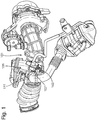
- Figures 1 and 2 show pressure measurement apparatus 101 comprising a differential pressure sensor 103 and a component 105 of a gas flow system of an engine, for example a component of an intake system or an exhaust system.
- the differential pressure sensor 103 is mounted directly to the said component 105 such that a sensor body 107 of the differential pressure sensor 103 extends through the said component 105 and into the gas flow path 109.
- the said component 105 is a low pressure Exhaust Gas Recirculation (EGR) valve 111.
- EGR Exhaust Gas Recirculation
- the said component 105 may be any appropriate portion of the intake system or the exhaust system.
- the differential pressure sensor 103 comprises a first pressure port 113A and a second pressure port 113B.
- the first pressure port 113A is configured to cooperate with an opening 115 in a wall of the EGR valve 111. In this manner, the first pressure port 113A extends though the opening 115 and terminates inside the EGR valve 111, which eliminates the need for a separate connector between the first pressure port 113A and the EGR valve 111.
- the second pressure port 113B terminates outside of EGR valve 111 so that it may be connected to another portion of the gas flow system to allow for a differential pressure measurement. Since no additional bracketry is required to mount the differential pressure sensor 103, the present invention is beneficial as it reduces the overall number of components assembled to the engine/vehicle in order to take differential pressure measurements.
- the body portion 107of the differential pressure sensor 103 may be configured to sealably engage the opening 115. Further, the engagement between the first pressure port 113A and the opening 115 may secure the differential pressure sensor 103 in position on the EGR valve 111.
- the fit between the first pressure port 113A and the opening may be an interference fit configured to hold the differential pressure sensor 103 in place when the first pressure port 113A is inserted into the opening 115.
- the differential pressure sensor 103 and/or the EGR valve may comprise one or more features, such as a clip or a snap fixing, configured to secure the differential pressure sensor 103 to the EGR valve 111.
- the body portion 107 of the differential pressure sensor 103 may be specially shaped so as to match the exterior form of the EGR valve 111, which may help reduce the packaging requirements of the vehicle and/or help secure the differential pressure sensor 103 to the EGR valve 111.
- the sensor body 107 is directly mounted to the outside wall of the EGR valve 111.
- the sensor body 107 is mounted directly over the opening 115 such that the first pressure port 113A extends directly through the wall of the EGR valve 111 and into the gas flow path 109.
- the sensor body 107 may be positioned remote from the opening 115, for example on a component next to or near to the EGR valve 111, and the first pressure port 113A may extend along an at least partially bent and/or curved path to allow the first pressure port 113A to extend directly through the wall of the EGR valve 111 without the need for one or more intermediary connectors.
- the present disclosure also provides a method of assembling the above described pressure measurement system 101 for an engine.
- the method may comprise assembling the differential pressure sensor 103 to a gas flow path component 105, such as the EGR valve 111, so that the first pressure port 113A terminates inside the gas flow path component 105 and the second pressure port 113B terminates outside of the gas flow path component 105, thereby defining a subassembly.
- the method may further comprise assembling the subassembly to the engine, for example at a different location to the location in which the subassembly was assembled.
- the method may further comprise connecting the second pressure port 113B of the differential pressure sensor 103 to another gas flow path component, for example once the subassembly has been installed to the engine.
- the pressure measurement system 101 can be supplied as a subassembly, which can be installed directly to the engine or the vehicle.
- the pressure measurement system 101 comprises the EGR valve 111
- an EGR valve manufacturer can supply the EGR valve 111 with the differential pressure sensor 103 pre-assembled to the EGR valve 111.
- an engine/vehicle manufacturer need not fix the differential pressure sensor 103 to the vehicle, and need only connect the second pressure port 113B of the differential pressure sensor 103 to another gas flow component, which reduces the time and cost associated with manufacturing the engine/vehicle.
- Pressure measurement apparatus for an engine comprising:
- Pressure measurement apparatus comprising a duct configured to connect one of the pressure ports to another gas flow path component of the intake system or the exhaust system.
- a differential pressure sensor for an intake system or an exhaust system of an engine having a body portion comprising first and second pressure ports, wherein at least one of the first and second pressure ports is configured to engage an opening in a wall of a gas flow path component of the intake system or the exhaust system so that at least one of the first and second pressure ports terminates inside the gas flow path component.
- a gas flow path component of an intake system or an exhaust system for an engine comprising an opening configured to receive a portion of a sensor body of a differential pressure sensor so that at least one of a first and second pressure port of the differential pressure sensor terminates inside the gas flow path component.
- a vehicle comprising at least one of the pressure measurement apparatus of any of statements 1 to 9, a differential pressure sensor of statement 10, and a gas flow path component of statement 11.
Landscapes
- Engineering & Computer Science (AREA)
- Chemical & Material Sciences (AREA)
- Combustion & Propulsion (AREA)
- Mechanical Engineering (AREA)
- General Engineering & Computer Science (AREA)
- Analytical Chemistry (AREA)
- Physics & Mathematics (AREA)
- Fluid Mechanics (AREA)
- Chemical Kinetics & Catalysis (AREA)
- General Physics & Mathematics (AREA)
- Measuring Fluid Pressure (AREA)
- Exhaust-Gas Circulating Devices (AREA)
- Measuring Volume Flow (AREA)
Abstract
Description
- This disclosure relates to pressure measurement apparatus for an engine, and in particular, but not exclusively, relates to an arrangement of a differential pressure sensor and a gas flow path component of an intake system or an exhaust system.
- It is common for an Exhaust Gas Recirculation (EGR) system of a vehicle to be fitted with a sensor to measure pressure changes across an EGR valve. For example, when exhaust gas flows through the EGR valve, a differential pressure sensor is able to measure the pressure difference across the valve, from which the mass flow rate of exhaust gas flowing through the EGR system can be determined.
- It is beneficial to ensure that the desired amount of exhaust gas is flowing through the EGR system to help reduce harmful emissions and the compliance with emissions standards in support of a clean environment, as well as improving the reliability of the engine.
- It is known to mount a differential pressure sensor of an EGR system close to an EGR valve using a bracket. The differential pressure sensor may then be fitted with two pipes, one of which is attached to one side of the EGR valve, e.g. to an air intake path of the engine, the other being attached to the other side of the EGR valve, e.g. to an exhaust gas flow path of the engine. Attaching the differential pressure sensor in this manner can introduce unnecessary cost and additional weight due to the required brackets, connecting pipes and clips, etc., and also provides an opportunity for the incorrect connection of pipes and damage to the connecting pipes.
- According to an aspect of the present disclosure there is provided pressure measurement apparatus for an engine, the pressure measurement apparatus comprising: a gas flow path component of a gas flow system of the engine, e.g. an intake system or an exhaust system; and a differential pressure sensor having a sensor body defining first and second pressure ports, wherein the sensor body is configured to cooperate with an opening in a wall of the gas flow path component so that the first pressure port terminates inside the gas flow path component, and the second pressure port terminates outside of the gas flow path component in an assembled configuration. For example, at least one of the first and second pressure ports may terminate in a gas flow path through the gas flow path component in an assembled configuration.
- In the context of the present disclosure, the term "gas flow system" of the engine is understood to mean a system comprising one or more gas flow path components being configured to direct gas flow towards and/or away from an engine. The gas flow system may comprise an exhaust system of the engine. Where the gas flow system comprises an exhaust system of the engine, the gas flow path component may be a component of the exhaust system, e.g. an exhaust manifold. The gas flow system may comprise an intake system of the engine. Where the gas flow system comprises an intake system of the engine, the gas flow path component may be a component of the intake system, e.g. an intake manifold. The gas flow system may comprise an exhaust gas recirculation system. Where the gas flow system may comprises an exhaust gas recirculation system, the gas flow path component may be an exhaust gas recirculation valve.
- The gas flow path component may be any component configured to direct gas flow. For example, the gas flow path component may be a valve assembly, and/or portion of ducting, tubing or conduit configured to flow gas towards and/or away from another gas flow path component of the gas flow system.
- The sensor body may be configured to sealably engage the opening in the wall of the gas flow path component. For example, at least one of the first pressure port, the second pressure port and the gas flow path component may comprise a seal configured to seal the opening when the sensor body engages the opening.
- The sensor body may be configured to mount directly onto the gas flow path component. The sensor body and the gas flow path component may each comprise corresponding mounting features that allow the sensor body to mount directly onto the gas flow path component. The differential pressure sensor may be securable to the gas flow path component by virtue of the interaction between the at least one of the first and second pressure ports and the opening in the wall of the gas flow path component.
- The sensor body may extend at least partially through the opening in the wall of the gas flow path component. The sensor body may be in direct fluidic communication with the gas flow though the gas flow path component, for example without the use of one or more intermediary connectors, such as a tube or duct.
- The pressure measurement system may comprise a duct configured to connect one of the pressure ports, for example the second pressure port, to another portion of the gas flow system.
- The gas flow path component may be an air flow path component. For example, the gas flow path component may be a component configured to flow air between one portion of the gas flow system and another portion of the gas flow system. The gas flow path component may be a component configured to flow exhaust gas between one portion of the gas flow system and another portion of the gas flow system. The gas flow path component may be a valve assembly of the gas flow system. The gas flow path component may be a control valve of an exhaust gas recirculation loop.
- The pressure measurement apparatus may comprise a controller configured to determine the pressure differential across the first and second pressure ports of the differential pressure sensor.
- According to another aspect of the present disclosure there is provided a differential pressure sensor for a gas flow system of an engine, the differential pressure sensor having a body portion comprising first and second pressure ports, wherein the body portion is configured to engage an opening in a wall of a gas flow path component, so that the first pressure port terminates inside the gas flow path component, and the second pressure port terminates outside of the gas flow path component in an assembled configuration.
- A gas flow path component of a gas flow system for an engine may be provided comprising at least one of the above-mentioned differential pressure sensors, the gas flow path component having a portion comprising an opening configured to receive a sensor body of a differential pressure sensor, so that at least one of a first and second pressure port of the differential pressure sensor terminates inside the gas flow path component.
- According to another aspect of the present disclosure there is provided an exhaust gas recirculation system for a vehicle, the exhaust gas recirculation system comprising: an exhaust gas recirculation valve; and a differential pressure sensor, wherein a body portion of the differential pressure sensor is in direct fluidic communication with a gas flow path of the exhaust gas recirculation valve.
- An engine or a vehicle may be provided comprising at least one of the above-mentioned pressure measurement apparatus, the differential pressure sensor, the gas flow path component, and the exhaust gas recirculation system.
- According to another aspect of the present disclosure there is provided a method of assembling pressure measurement apparatus for an engine as described in claim 11 of the appended claims.
- The method may further comprise assembling the subassembly to the engine. The method may further comprise connecting the second pressure port of the differential pressure sensor to another gas flow path component, e.g. after installing the subassembly to the engine.
- To avoid unnecessary duplication of effort and repetition of text in the specification, certain features are described in relation to only one or several aspects or arrangements of the disclosure. However, it is to be understood that, where it is technically possible, features described in relation to any aspect or arrangement of the disclosure may also be used with any other aspect or arrangement of the disclosure.
- For a better understanding of the present disclosure, and to show more clearly how it may be carried into effect, reference will now be made, by way of example, to the accompanying drawings, in which:
-
Figure 1 shows a portion of an exhaust gas recirculation system of an engine; and -
Figure 2 shows a detailed view of a differential pressure sensor installed to the exhaust gas recirculation system. - An engine for a vehicle can be fitted with an intake system and/or an exhaust system that each typically comprise several different components configured to control and/or direct the flow of gas towards and/or away from the engine. Further, it is common to use a differential pressure sensor to measure the difference in operating pressures between two different portions of the intake system or the exhaust system. For example, a differential pressure sensor may be used to measure the pressure difference across an exhaust gas recirculation valve or the pressure difference across a particulate filter of the exhaust system. It is understood, therefore, that a differential pressure sensor may be installed across any appropriate portion of the intake system or the exhaust system, depending on the desired location of pressure measurement.
- In order to mount the differential pressure sensor in a convenient position to take a pressure measurement, the differential pressure sensor is usually attached to a bracket, which can be secured to an appropriate portion of the engine or vehicle. Each pressure port of the differential pressure sensor can then be connected, for example using a tube or duct, to a desired portion of the intake system or the exhaust system. The present invention provides pressure measurement apparatus which simplifies the installation of the differential pressure sensor, which can reduce cost and weight, and can increase the ease of manufacture/assembly of the engine or vehicle.
-
Figures 1 and2 showpressure measurement apparatus 101 comprising adifferential pressure sensor 103 and acomponent 105 of a gas flow system of an engine, for example a component of an intake system or an exhaust system. Thedifferential pressure sensor 103 is mounted directly to the saidcomponent 105 such that asensor body 107 of thedifferential pressure sensor 103 extends through the saidcomponent 105 and into thegas flow path 109. Infigures 1 and2 , the saidcomponent 105 is a low pressure Exhaust Gas Recirculation (EGR)valve 111. However, thesaid component 105 may be any appropriate portion of the intake system or the exhaust system. - The
differential pressure sensor 103 comprises afirst pressure port 113A and asecond pressure port 113B. As shown infigure 2 , thefirst pressure port 113A is configured to cooperate with anopening 115 in a wall of theEGR valve 111. In this manner, thefirst pressure port 113A extends though theopening 115 and terminates inside theEGR valve 111, which eliminates the need for a separate connector between thefirst pressure port 113A and theEGR valve 111. When thedifferential pressure sensor 103 is assembled to theEGR valve 111, thesecond pressure port 113B terminates outside ofEGR valve 111 so that it may be connected to another portion of the gas flow system to allow for a differential pressure measurement. Since no additional bracketry is required to mount thedifferential pressure sensor 103, the present invention is beneficial as it reduces the overall number of components assembled to the engine/vehicle in order to take differential pressure measurements. - In one arrangement, the body portion 107of the
differential pressure sensor 103 may be configured to sealably engage theopening 115. Further, the engagement between thefirst pressure port 113A and theopening 115 may secure thedifferential pressure sensor 103 in position on theEGR valve 111. For example, the fit between thefirst pressure port 113A and the opening may be an interference fit configured to hold thedifferential pressure sensor 103 in place when thefirst pressure port 113A is inserted into theopening 115. Additionally or alternatively, thedifferential pressure sensor 103 and/or the EGR valve may comprise one or more features, such as a clip or a snap fixing, configured to secure thedifferential pressure sensor 103 to theEGR valve 111. In one arrangement, thebody portion 107 of thedifferential pressure sensor 103 may be specially shaped so as to match the exterior form of theEGR valve 111, which may help reduce the packaging requirements of the vehicle and/or help secure thedifferential pressure sensor 103 to theEGR valve 111. - In the arrangement shown in
figures 1 and2 , thesensor body 107 is directly mounted to the outside wall of theEGR valve 111. In particular, thesensor body 107 is mounted directly over theopening 115 such that thefirst pressure port 113A extends directly through the wall of theEGR valve 111 and into thegas flow path 109. In one or more other arrangements, thesensor body 107 may be positioned remote from theopening 115, for example on a component next to or near to theEGR valve 111, and thefirst pressure port 113A may extend along an at least partially bent and/or curved path to allow thefirst pressure port 113A to extend directly through the wall of theEGR valve 111 without the need for one or more intermediary connectors. - The present disclosure also provides a method of assembling the above described
pressure measurement system 101 for an engine. For example, the method may comprise assembling thedifferential pressure sensor 103 to a gasflow path component 105, such as theEGR valve 111, so that thefirst pressure port 113A terminates inside the gasflow path component 105 and thesecond pressure port 113B terminates outside of the gasflow path component 105, thereby defining a subassembly. The method may further comprise assembling the subassembly to the engine, for example at a different location to the location in which the subassembly was assembled. The method may further comprise connecting thesecond pressure port 113B of thedifferential pressure sensor 103 to another gas flow path component, for example once the subassembly has been installed to the engine. - One advantage of the present invention is that the
pressure measurement system 101 can be supplied as a subassembly, which can be installed directly to the engine or the vehicle. For example, where thepressure measurement system 101 comprises theEGR valve 111, an EGR valve manufacturer can supply theEGR valve 111 with thedifferential pressure sensor 103 pre-assembled to theEGR valve 111. In this manner, an engine/vehicle manufacturer need not fix thedifferential pressure sensor 103 to the vehicle, and need only connect thesecond pressure port 113B of thedifferential pressure sensor 103 to another gas flow component, which reduces the time and cost associated with manufacturing the engine/vehicle. - Statement 1. Pressure measurement apparatus for an engine, the pressure measurement apparatus comprising:
- a gas flow path component of one of an intake system or an exhaust system; and
- a differential pressure sensor having a sensor body defining first and second pressure ports, wherein the sensor body is configured to cooperate with an opening in a wall of the gas flow path component so that at least one of the first and second pressure ports terminates inside the gas flow path component in an assembled configuration.
- Statement 2. Pressure measurement apparatus according to statement 1, wherein the sensor body is configured to mount directly onto the gas flow path component.
- Statement 3. Pressure measurement apparatus according to any of the preceding statements, wherein the sensor body extends at least partially through the opening in the wall of the gas flow path component.
- Statement 4. Pressure measurement apparatus according to any of the preceding statements, wherein the sensor body sealably engages the opening in the wall of the gas flow path component.
- Statement 5. Pressure measurement apparatus according to any of the preceding statements, wherein one of the pressure ports terminates outside of the gas flow path component.
- Statement 6. Pressure measurement apparatus according any of the preceding statements, the pressure measurement apparatus comprising a duct configured to connect one of the pressure ports to another gas flow path component of the intake system or the exhaust system.
- Statement 7. Pressure measurement apparatus according any of the preceding statements, wherein the gas flow path component is an air flow path component.
- Statement 8. Pressure measurement apparatus according any of the preceding statements, wherein the gas flow path component is a valve assembly of the intake system or the exhaust system.
- Statement 9. Pressure measurement apparatus according to statement 8, wherein the valve assembly is a control valve of an exhaust gas recirculation loop.
- Statement 10. A differential pressure sensor for an intake system or an exhaust system of an engine, the differential pressure sensor having a body portion comprising first and second pressure ports, wherein at least one of the first and second pressure ports is configured to engage an opening in a wall of a gas flow path component of the intake system or the exhaust system so that at least one of the first and second pressure ports terminates inside the gas flow path component.
- Statement 11. A gas flow path component of an intake system or an exhaust system for an engine, the gas flow path component comprising an opening configured to receive a portion of a sensor body of a differential pressure sensor so that at least one of a first and second pressure port of the differential pressure sensor terminates inside the gas flow path component.
- Statement 12. A vehicle comprising at least one of the pressure measurement apparatus of any of statements 1 to 9, a differential pressure sensor of statement 10, and a gas flow path component of statement 11.
- It will be appreciated by those skilled in the art that although the invention has been described by way of example with reference to one or more arrangements, it is not limited to the disclosed arrangements and alternative arrangements could be constructed without departing from the scope of the invention as defined by the appended claims.
Claims (15)
- Pressure measurement apparatus for an engine, the pressure measurement apparatus comprising:a gas flow path component of a gas flow system of an engine; anda differential pressure sensor having a sensor body defining first and second pressure ports, wherein the sensor body is configured to cooperate with an opening in a wall of the gas flow path component so that the first pressure port terminates inside the gas flow path component and the second pressure port terminates outside of the gas flow path component in an assembled configuration.
- Pressure measurement apparatus according to claim 1, wherein the sensor body is configured to mount directly onto the gas flow path component.
- Pressure measurement apparatus according to any of the preceding claims, wherein the sensor body extends at least partially through the opening in the wall of the gas flow path component.
- Pressure measurement apparatus according to any of the preceding claims, wherein the first pressure port extends at least partially through the opening in the wall of the gas flow path component.
- Pressure measurement apparatus according to any of the preceding claims, wherein the sensor body sealably engages the opening in the wall of the gas flow path component.
- Pressure measurement apparatus according any of the preceding claims, the pressure measurement apparatus comprising a duct configured to connect the second pressure port to another gas flow path component of the gas flow system.
- Pressure measurement apparatus according any of the preceding claims, wherein the gas flow path component is an air flow path component.
- Pressure measurement apparatus according any of the preceding claims, wherein the gas flow path component is a valve assembly of the intake system or the exhaust system.
- Pressure measurement apparatus according to claim 8, wherein the valve assembly is a control valve of an exhaust gas recirculation loop.
- Pressure measurement apparatus according any of the preceding claims, wherein the gas flow system comprises one of an intake system of the engine and an exhaust system of the engine.
- A differential pressure sensor for a gas flow system of an engine, the differential pressure sensor having a body portion comprising first and second pressure ports, wherein the first pressure port is configured to engage an opening in a wall of a gas flow path component of the intake system or the exhaust system so that the first pressure port terminates inside the gas flow path component, the second pressure port being configured to terminate outside of the gas flow path component in an assembled configuration.
- A vehicle comprising at least one of the pressure measurement apparatus of any of claims 1 to 10, and a differential pressure sensor of claim 11.
- A method of assembling pressure measurement apparatus for an engine, the pressure measurement apparatus comprising:a gas flow path component of a gas flow system of the engine; anda differential pressure sensor having a sensor body defining first and second pressure ports, wherein the sensor body is configured to cooperate with an opening in a wall of the gas flow path component, the method comprising:assembling the differential pressure sensor to the gas flow path component so that the first pressure port terminates inside the gas flow path component and the second pressure port terminates outside of the gas flow path component, thereby defining a subassembly.
- A method according to claim 13, the method further comprising assembling the subassembly to the engine.
- A method according to claim 14, the method further comprising connecting the second pressure port of the differential pressure sensor to another gas flow path component.
Applications Claiming Priority (1)
| Application Number | Priority Date | Filing Date | Title |
|---|---|---|---|
| GB1619212.2A GB2555849B (en) | 2016-11-14 | 2016-11-14 | Pressure measurement apparatus for an engine |
Publications (2)
| Publication Number | Publication Date |
|---|---|
| EP3321495A1 true EP3321495A1 (en) | 2018-05-16 |
| EP3321495B1 EP3321495B1 (en) | 2023-06-07 |
Family
ID=60327179
Family Applications (1)
| Application Number | Title | Priority Date | Filing Date |
|---|---|---|---|
| EP17201725.3A Active EP3321495B1 (en) | 2016-11-14 | 2017-11-14 | Pressure measurement apparatus for an engine |
Country Status (6)
| Country | Link |
|---|---|
| US (1) | US10830190B2 (en) |
| EP (1) | EP3321495B1 (en) |
| CN (1) | CN108071525B (en) |
| GB (1) | GB2555849B (en) |
| MX (1) | MX2017014512A (en) |
| RU (1) | RU2017136713A (en) |
Families Citing this family (1)
| Publication number | Priority date | Publication date | Assignee | Title |
|---|---|---|---|---|
| GB2549286B (en) * | 2016-04-11 | 2019-07-24 | Perkins Engines Co Ltd | EGR valve with integrated sensor |
Citations (3)
| Publication number | Priority date | Publication date | Assignee | Title |
|---|---|---|---|---|
| US5613479A (en) * | 1995-12-08 | 1997-03-25 | Ford Motor Company | Pressure feedback exhaust gas recirculation system |
| US6415777B1 (en) * | 2000-11-28 | 2002-07-09 | Siemens Automotive Inc. | EGR module having orifice in a pressure sensing port |
| US20040168508A1 (en) * | 2003-02-28 | 2004-09-02 | Cummins Inc. | Exhaust gas recirculation measurement device |
Family Cites Families (20)
| Publication number | Priority date | Publication date | Assignee | Title |
|---|---|---|---|---|
| DE2949507A1 (en) * | 1979-12-08 | 1981-06-11 | Robert Bosch Gmbh, 7000 Stuttgart | DEVICE FOR CONTROLLING THE COMPOSITION OF THE OPERATING MIXTURE TO BE INTEGRATED INTO THE COMBUSTION ROOM OF AN INTERNAL COMBUSTION ENGINE |
| WO2001012972A1 (en) * | 1999-08-17 | 2001-02-22 | Siemens Canada Limited | Exhaust gas recirculation system module |
| US6470866B2 (en) * | 2000-01-05 | 2002-10-29 | Siemens Canada Limited | Diesel engine exhaust gas recirculation (EGR) system and method |
| US20090084193A1 (en) * | 2007-09-27 | 2009-04-02 | Victor Cerabone | Apparatus for measuring an exhaust gas recirculation flow of an internal combustion engine |
| US9051904B2 (en) * | 2010-04-30 | 2015-06-09 | Yanmar Co., Ltd. | Engine |
| JP5608614B2 (en) * | 2011-07-25 | 2014-10-15 | 日立オートモティブシステムズ株式会社 | Engine EGR flow rate detection device |
| US9181905B2 (en) * | 2011-09-25 | 2015-11-10 | Cummins Inc. | System for controlling an air handling system including an electric pump-assisted exhaust gas recirculation |
| US8938961B2 (en) * | 2011-12-30 | 2015-01-27 | Caterpillar Inc. | EGR flow sensor for an engine |
| JP5982203B2 (en) * | 2012-07-11 | 2016-08-31 | 日立オートモティブシステムズ株式会社 | Control device for internal combustion engine |
| JP5761138B2 (en) * | 2012-08-24 | 2015-08-12 | 株式会社デンソー | EGR device and EGR valve characteristic inspection device |
| CN103105297A (en) * | 2013-01-14 | 2013-05-15 | 奇瑞汽车股份有限公司 | Direct measurement method of engine exhaust gas recirculation (EGR) rate and engine EGR valve |
| US20150059713A1 (en) * | 2013-08-27 | 2015-03-05 | Deere & Company | Intake manifold |
| DE102013113594A1 (en) * | 2013-12-06 | 2015-06-11 | Endress + Hauser Gmbh + Co. Kg | Differential Pressure Sensor |
| CN204226006U (en) * | 2014-09-29 | 2015-03-25 | 东风康明斯发动机有限公司 | A kind of EGR diesel engine |
| US9528476B2 (en) * | 2014-12-17 | 2016-12-27 | Ford Global Technologies, Llc | Methods and systems for diagnosing an intake oxygen sensor based on pressure |
| CN104747307B (en) * | 2015-02-13 | 2017-07-28 | 长城汽车股份有限公司 | Using the control method, system and vehicle of the supercharging gasoline engine of egr system |
| CN204493018U (en) * | 2015-03-27 | 2015-07-22 | 北京汽车动力总成有限公司 | A kind of gas recirculation system and automobile |
| DE102015008359A1 (en) * | 2015-06-27 | 2016-12-29 | Daimler Ag | Measuring device for a motor vehicle and method for cleaning such a measuring device |
| CN205135853U (en) * | 2015-10-23 | 2016-04-06 | 王淼 | Efficient mass transfer device of fuel oil engine |
| CN205559110U (en) * | 2016-03-15 | 2016-09-07 | 潍柴动力股份有限公司 | Measurable exhaust gas flow's venturi |
-
2016
- 2016-11-14 GB GB1619212.2A patent/GB2555849B/en active Active
-
2017
- 2017-10-18 RU RU2017136713A patent/RU2017136713A/en not_active Application Discontinuation
- 2017-11-07 US US15/805,596 patent/US10830190B2/en active Active
- 2017-11-13 MX MX2017014512A patent/MX2017014512A/en unknown
- 2017-11-13 CN CN201711113702.0A patent/CN108071525B/en active Active
- 2017-11-14 EP EP17201725.3A patent/EP3321495B1/en active Active
Patent Citations (3)
| Publication number | Priority date | Publication date | Assignee | Title |
|---|---|---|---|---|
| US5613479A (en) * | 1995-12-08 | 1997-03-25 | Ford Motor Company | Pressure feedback exhaust gas recirculation system |
| US6415777B1 (en) * | 2000-11-28 | 2002-07-09 | Siemens Automotive Inc. | EGR module having orifice in a pressure sensing port |
| US20040168508A1 (en) * | 2003-02-28 | 2004-09-02 | Cummins Inc. | Exhaust gas recirculation measurement device |
Also Published As
| Publication number | Publication date |
|---|---|
| EP3321495B1 (en) | 2023-06-07 |
| US20180135570A1 (en) | 2018-05-17 |
| US10830190B2 (en) | 2020-11-10 |
| GB2555849A (en) | 2018-05-16 |
| CN108071525A (en) | 2018-05-25 |
| MX2017014512A (en) | 2018-10-04 |
| CN108071525B (en) | 2021-08-24 |
| RU2017136713A (en) | 2019-04-18 |
| GB2555849B (en) | 2020-03-11 |
Similar Documents
| Publication | Publication Date | Title |
|---|---|---|
| US8991352B2 (en) | Intake manifold section and intake system | |
| JP5396410B2 (en) | Sensor structure | |
| US20060196462A1 (en) | Air intake for motor vehicles | |
| CN107076632B (en) | Pressure sensor for detecting the pressure of fluid medium | |
| JPS6057093A (en) | Damper | |
| US20130330237A1 (en) | Aftertreatment manifold device | |
| KR102180393B1 (en) | Internal combustion engine comprising a venturi nozzle provided inside a fluid-guiding component which is fluidally connected with a tank vent line | |
| CN104040127B (en) | Delivery unit for delivery of liquid additives | |
| CN101210508A (en) | Variable geometry muffler of an exhaust system of an internal combustion engine | |
| EP3321495B1 (en) | Pressure measurement apparatus for an engine | |
| US8555846B2 (en) | Air purifier having resonator installed in the air outlet | |
| CN110905696B (en) | Internal combustion engine with valve and flow guide member | |
| CN103174562A (en) | Arrangement of a suction device for an auxiliary apparatus | |
| CN110410174B (en) | Crankcase ventilation system, engine assembly and fuel type vehicle | |
| CN104755741B (en) | device for delivering fuel | |
| CN102272429B (en) | Throttle plate device | |
| JPH0573254U (en) | Evaporative emission control device for fuel | |
| CN101666276B (en) | Tube device for a motor vehicle air filter system and related method of assembly | |
| CN201463991U (en) | Oil mass sensor of vehicle | |
| CN212106022U (en) | Automobile exhaust pipe assembly | |
| KR20080005669A (en) | Combined Structure of Automotive Fuzzy Control Solenoid Valve | |
| US7063060B2 (en) | Air induction system having an intake manifold including a throttle body | |
| US6460523B1 (en) | EGR system for an internal combustion engine | |
| CN219865276U (en) | Fixed bolster and vehicle | |
| CN210890310U (en) | Solenoid Valve, Mounting Assembly for Sensor Mounting, and Sensor Assembly |
Legal Events
| Date | Code | Title | Description |
|---|---|---|---|
| PUAI | Public reference made under article 153(3) epc to a published international application that has entered the european phase |
Free format text: ORIGINAL CODE: 0009012 |
|
| STAA | Information on the status of an ep patent application or granted ep patent |
Free format text: STATUS: THE APPLICATION HAS BEEN PUBLISHED |
|
| AK | Designated contracting states |
Kind code of ref document: A1 Designated state(s): AL AT BE BG CH CY CZ DE DK EE ES FI FR GB GR HR HU IE IS IT LI LT LU LV MC MK MT NL NO PL PT RO RS SE SI SK SM TR |
|
| AX | Request for extension of the european patent |
Extension state: BA ME |
|
| STAA | Information on the status of an ep patent application or granted ep patent |
Free format text: STATUS: REQUEST FOR EXAMINATION WAS MADE |
|
| 17P | Request for examination filed |
Effective date: 20181003 |
|
| RBV | Designated contracting states (corrected) |
Designated state(s): AL AT BE BG CH CY CZ DE DK EE ES FI FR GB GR HR HU IE IS IT LI LT LU LV MC MK MT NL NO PL PT RO RS SE SI SK SM TR |
|
| STAA | Information on the status of an ep patent application or granted ep patent |
Free format text: STATUS: EXAMINATION IS IN PROGRESS |
|
| 17Q | First examination report despatched |
Effective date: 20210512 |
|
| RIC1 | Information provided on ipc code assigned before grant |
Ipc: F02M 35/10 20060101ALI20221221BHEP Ipc: G01F 1/36 20060101ALI20221221BHEP Ipc: F02M 26/73 20160101ALI20221221BHEP Ipc: F02M 26/61 20160101ALI20221221BHEP Ipc: F02M 26/47 20160101AFI20221221BHEP |
|
| GRAP | Despatch of communication of intention to grant a patent |
Free format text: ORIGINAL CODE: EPIDOSNIGR1 |
|
| STAA | Information on the status of an ep patent application or granted ep patent |
Free format text: STATUS: GRANT OF PATENT IS INTENDED |
|
| INTG | Intention to grant announced |
Effective date: 20230201 |
|
| GRAS | Grant fee paid |
Free format text: ORIGINAL CODE: EPIDOSNIGR3 |
|
| GRAA | (expected) grant |
Free format text: ORIGINAL CODE: 0009210 |
|
| STAA | Information on the status of an ep patent application or granted ep patent |
Free format text: STATUS: THE PATENT HAS BEEN GRANTED |
|
| RBV | Designated contracting states (corrected) |
Designated state(s): AL AT BE BG CH CY CZ DE DK EE ES FI FR GR HR HU IE IS IT LI LT LU LV MC MK MT NL NO PL PT RO RS SE SI SK SM TR |
|
| AK | Designated contracting states |
Kind code of ref document: B1 Designated state(s): AL AT BE BG CH CY CZ DE DK EE ES FI FR GR HR HU IE IS IT LI LT LU LV MC MK MT NL NO PL PT RO RS SE SI SK SM TR |
|
| REG | Reference to a national code |
Ref country code: CH Ref legal event code: EP Ref country code: AT Ref legal event code: REF Ref document number: 1575759 Country of ref document: AT Kind code of ref document: T Effective date: 20230615 |
|
| REG | Reference to a national code |
Ref country code: DE Ref legal event code: R096 Ref document number: 602017069394 Country of ref document: DE |
|
| P01 | Opt-out of the competence of the unified patent court (upc) registered |
Effective date: 20230620 |
|
| REG | Reference to a national code |
Ref country code: LT Ref legal event code: MG9D |
|
| REG | Reference to a national code |
Ref country code: NL Ref legal event code: MP Effective date: 20230607 |
|
| PG25 | Lapsed in a contracting state [announced via postgrant information from national office to epo] |
Ref country code: SE Free format text: LAPSE BECAUSE OF FAILURE TO SUBMIT A TRANSLATION OF THE DESCRIPTION OR TO PAY THE FEE WITHIN THE PRESCRIBED TIME-LIMIT Effective date: 20230607 Ref country code: NO Free format text: LAPSE BECAUSE OF FAILURE TO SUBMIT A TRANSLATION OF THE DESCRIPTION OR TO PAY THE FEE WITHIN THE PRESCRIBED TIME-LIMIT Effective date: 20230907 Ref country code: ES Free format text: LAPSE BECAUSE OF FAILURE TO SUBMIT A TRANSLATION OF THE DESCRIPTION OR TO PAY THE FEE WITHIN THE PRESCRIBED TIME-LIMIT Effective date: 20230607 |
|
| REG | Reference to a national code |
Ref country code: AT Ref legal event code: MK05 Ref document number: 1575759 Country of ref document: AT Kind code of ref document: T Effective date: 20230607 |
|
| PG25 | Lapsed in a contracting state [announced via postgrant information from national office to epo] |
Ref country code: RS Free format text: LAPSE BECAUSE OF FAILURE TO SUBMIT A TRANSLATION OF THE DESCRIPTION OR TO PAY THE FEE WITHIN THE PRESCRIBED TIME-LIMIT Effective date: 20230607 Ref country code: NL Free format text: LAPSE BECAUSE OF FAILURE TO SUBMIT A TRANSLATION OF THE DESCRIPTION OR TO PAY THE FEE WITHIN THE PRESCRIBED TIME-LIMIT Effective date: 20230607 Ref country code: LV Free format text: LAPSE BECAUSE OF FAILURE TO SUBMIT A TRANSLATION OF THE DESCRIPTION OR TO PAY THE FEE WITHIN THE PRESCRIBED TIME-LIMIT Effective date: 20230607 Ref country code: LT Free format text: LAPSE BECAUSE OF FAILURE TO SUBMIT A TRANSLATION OF THE DESCRIPTION OR TO PAY THE FEE WITHIN THE PRESCRIBED TIME-LIMIT Effective date: 20230607 Ref country code: HR Free format text: LAPSE BECAUSE OF FAILURE TO SUBMIT A TRANSLATION OF THE DESCRIPTION OR TO PAY THE FEE WITHIN THE PRESCRIBED TIME-LIMIT Effective date: 20230607 Ref country code: GR Free format text: LAPSE BECAUSE OF FAILURE TO SUBMIT A TRANSLATION OF THE DESCRIPTION OR TO PAY THE FEE WITHIN THE PRESCRIBED TIME-LIMIT Effective date: 20230908 |
|
| PG25 | Lapsed in a contracting state [announced via postgrant information from national office to epo] |
Ref country code: FI Free format text: LAPSE BECAUSE OF FAILURE TO SUBMIT A TRANSLATION OF THE DESCRIPTION OR TO PAY THE FEE WITHIN THE PRESCRIBED TIME-LIMIT Effective date: 20230607 |
|
| PG25 | Lapsed in a contracting state [announced via postgrant information from national office to epo] |
Ref country code: SK Free format text: LAPSE BECAUSE OF FAILURE TO SUBMIT A TRANSLATION OF THE DESCRIPTION OR TO PAY THE FEE WITHIN THE PRESCRIBED TIME-LIMIT Effective date: 20230607 |
|
| PG25 | Lapsed in a contracting state [announced via postgrant information from national office to epo] |
Ref country code: IS Free format text: LAPSE BECAUSE OF FAILURE TO SUBMIT A TRANSLATION OF THE DESCRIPTION OR TO PAY THE FEE WITHIN THE PRESCRIBED TIME-LIMIT Effective date: 20231007 |
|
| PG25 | Lapsed in a contracting state [announced via postgrant information from national office to epo] |
Ref country code: SM Free format text: LAPSE BECAUSE OF FAILURE TO SUBMIT A TRANSLATION OF THE DESCRIPTION OR TO PAY THE FEE WITHIN THE PRESCRIBED TIME-LIMIT Effective date: 20230607 Ref country code: SK Free format text: LAPSE BECAUSE OF FAILURE TO SUBMIT A TRANSLATION OF THE DESCRIPTION OR TO PAY THE FEE WITHIN THE PRESCRIBED TIME-LIMIT Effective date: 20230607 Ref country code: RO Free format text: LAPSE BECAUSE OF FAILURE TO SUBMIT A TRANSLATION OF THE DESCRIPTION OR TO PAY THE FEE WITHIN THE PRESCRIBED TIME-LIMIT Effective date: 20230607 Ref country code: PT Free format text: LAPSE BECAUSE OF FAILURE TO SUBMIT A TRANSLATION OF THE DESCRIPTION OR TO PAY THE FEE WITHIN THE PRESCRIBED TIME-LIMIT Effective date: 20231009 Ref country code: IS Free format text: LAPSE BECAUSE OF FAILURE TO SUBMIT A TRANSLATION OF THE DESCRIPTION OR TO PAY THE FEE WITHIN THE PRESCRIBED TIME-LIMIT Effective date: 20231007 Ref country code: EE Free format text: LAPSE BECAUSE OF FAILURE TO SUBMIT A TRANSLATION OF THE DESCRIPTION OR TO PAY THE FEE WITHIN THE PRESCRIBED TIME-LIMIT Effective date: 20230607 Ref country code: CZ Free format text: LAPSE BECAUSE OF FAILURE TO SUBMIT A TRANSLATION OF THE DESCRIPTION OR TO PAY THE FEE WITHIN THE PRESCRIBED TIME-LIMIT Effective date: 20230607 Ref country code: AT Free format text: LAPSE BECAUSE OF FAILURE TO SUBMIT A TRANSLATION OF THE DESCRIPTION OR TO PAY THE FEE WITHIN THE PRESCRIBED TIME-LIMIT Effective date: 20230607 |
|
| PG25 | Lapsed in a contracting state [announced via postgrant information from national office to epo] |
Ref country code: PL Free format text: LAPSE BECAUSE OF FAILURE TO SUBMIT A TRANSLATION OF THE DESCRIPTION OR TO PAY THE FEE WITHIN THE PRESCRIBED TIME-LIMIT Effective date: 20230607 |
|
| REG | Reference to a national code |
Ref country code: DE Ref legal event code: R097 Ref document number: 602017069394 Country of ref document: DE |
|
| PLBE | No opposition filed within time limit |
Free format text: ORIGINAL CODE: 0009261 |
|
| STAA | Information on the status of an ep patent application or granted ep patent |
Free format text: STATUS: NO OPPOSITION FILED WITHIN TIME LIMIT |
|
| PG25 | Lapsed in a contracting state [announced via postgrant information from national office to epo] |
Ref country code: DK Free format text: LAPSE BECAUSE OF FAILURE TO SUBMIT A TRANSLATION OF THE DESCRIPTION OR TO PAY THE FEE WITHIN THE PRESCRIBED TIME-LIMIT Effective date: 20230607 |
|
| PG25 | Lapsed in a contracting state [announced via postgrant information from national office to epo] |
Ref country code: SI Free format text: LAPSE BECAUSE OF FAILURE TO SUBMIT A TRANSLATION OF THE DESCRIPTION OR TO PAY THE FEE WITHIN THE PRESCRIBED TIME-LIMIT Effective date: 20230607 |
|
| 26N | No opposition filed |
Effective date: 20240308 |
|
| PG25 | Lapsed in a contracting state [announced via postgrant information from national office to epo] |
Ref country code: SI Free format text: LAPSE BECAUSE OF FAILURE TO SUBMIT A TRANSLATION OF THE DESCRIPTION OR TO PAY THE FEE WITHIN THE PRESCRIBED TIME-LIMIT Effective date: 20230607 Ref country code: IT Free format text: LAPSE BECAUSE OF FAILURE TO SUBMIT A TRANSLATION OF THE DESCRIPTION OR TO PAY THE FEE WITHIN THE PRESCRIBED TIME-LIMIT Effective date: 20230607 |
|
| REG | Reference to a national code |
Ref country code: CH Ref legal event code: PL |
|
| PG25 | Lapsed in a contracting state [announced via postgrant information from national office to epo] |
Ref country code: MC Free format text: LAPSE BECAUSE OF FAILURE TO SUBMIT A TRANSLATION OF THE DESCRIPTION OR TO PAY THE FEE WITHIN THE PRESCRIBED TIME-LIMIT Effective date: 20230607 |
|
| PG25 | Lapsed in a contracting state [announced via postgrant information from national office to epo] |
Ref country code: LU Free format text: LAPSE BECAUSE OF NON-PAYMENT OF DUE FEES Effective date: 20231114 |
|
| PG25 | Lapsed in a contracting state [announced via postgrant information from national office to epo] |
Ref country code: CH Free format text: LAPSE BECAUSE OF NON-PAYMENT OF DUE FEES Effective date: 20231130 |
|
| PG25 | Lapsed in a contracting state [announced via postgrant information from national office to epo] |
Ref country code: MC Free format text: LAPSE BECAUSE OF FAILURE TO SUBMIT A TRANSLATION OF THE DESCRIPTION OR TO PAY THE FEE WITHIN THE PRESCRIBED TIME-LIMIT Effective date: 20230607 Ref country code: LU Free format text: LAPSE BECAUSE OF NON-PAYMENT OF DUE FEES Effective date: 20231114 Ref country code: CH Free format text: LAPSE BECAUSE OF NON-PAYMENT OF DUE FEES Effective date: 20231130 |
|
| REG | Reference to a national code |
Ref country code: BE Ref legal event code: MM Effective date: 20231130 |
|
| REG | Reference to a national code |
Ref country code: IE Ref legal event code: MM4A |
|
| PG25 | Lapsed in a contracting state [announced via postgrant information from national office to epo] |
Ref country code: IE Free format text: LAPSE BECAUSE OF NON-PAYMENT OF DUE FEES Effective date: 20231114 |
|
| PG25 | Lapsed in a contracting state [announced via postgrant information from national office to epo] |
Ref country code: BE Free format text: LAPSE BECAUSE OF NON-PAYMENT OF DUE FEES Effective date: 20231130 |
|
| PG25 | Lapsed in a contracting state [announced via postgrant information from national office to epo] |
Ref country code: FR Free format text: LAPSE BECAUSE OF NON-PAYMENT OF DUE FEES Effective date: 20231130 |
|
| PG25 | Lapsed in a contracting state [announced via postgrant information from national office to epo] |
Ref country code: IE Free format text: LAPSE BECAUSE OF NON-PAYMENT OF DUE FEES Effective date: 20231114 Ref country code: FR Free format text: LAPSE BECAUSE OF NON-PAYMENT OF DUE FEES Effective date: 20231130 Ref country code: BE Free format text: LAPSE BECAUSE OF NON-PAYMENT OF DUE FEES Effective date: 20231130 |
|
| PG25 | Lapsed in a contracting state [announced via postgrant information from national office to epo] |
Ref country code: BG Free format text: LAPSE BECAUSE OF FAILURE TO SUBMIT A TRANSLATION OF THE DESCRIPTION OR TO PAY THE FEE WITHIN THE PRESCRIBED TIME-LIMIT Effective date: 20230607 |
|
| PG25 | Lapsed in a contracting state [announced via postgrant information from national office to epo] |
Ref country code: BG Free format text: LAPSE BECAUSE OF FAILURE TO SUBMIT A TRANSLATION OF THE DESCRIPTION OR TO PAY THE FEE WITHIN THE PRESCRIBED TIME-LIMIT Effective date: 20230607 |
|
| PG25 | Lapsed in a contracting state [announced via postgrant information from national office to epo] |
Ref country code: CY Free format text: LAPSE BECAUSE OF FAILURE TO SUBMIT A TRANSLATION OF THE DESCRIPTION OR TO PAY THE FEE WITHIN THE PRESCRIBED TIME-LIMIT; INVALID AB INITIO Effective date: 20171114 |
|
| PG25 | Lapsed in a contracting state [announced via postgrant information from national office to epo] |
Ref country code: HU Free format text: LAPSE BECAUSE OF FAILURE TO SUBMIT A TRANSLATION OF THE DESCRIPTION OR TO PAY THE FEE WITHIN THE PRESCRIBED TIME-LIMIT; INVALID AB INITIO Effective date: 20171114 |
|
| PG25 | Lapsed in a contracting state [announced via postgrant information from national office to epo] |
Ref country code: TR Free format text: LAPSE BECAUSE OF FAILURE TO SUBMIT A TRANSLATION OF THE DESCRIPTION OR TO PAY THE FEE WITHIN THE PRESCRIBED TIME-LIMIT Effective date: 20230607 |
|
| PGFP | Annual fee paid to national office [announced via postgrant information from national office to epo] |
Ref country code: DE Payment date: 20251013 Year of fee payment: 9 |