EP3321481A1 - Fluid supply over range of gravitational conditions - Google Patents
Fluid supply over range of gravitational conditions Download PDFInfo
- Publication number
- EP3321481A1 EP3321481A1 EP17201263.5A EP17201263A EP3321481A1 EP 3321481 A1 EP3321481 A1 EP 3321481A1 EP 17201263 A EP17201263 A EP 17201263A EP 3321481 A1 EP3321481 A1 EP 3321481A1
- Authority
- EP
- European Patent Office
- Prior art keywords
- conduit
- fluid
- tank
- density
- mass
- Prior art date
- Legal status (The legal status is an assumption and is not a legal conclusion. Google has not performed a legal analysis and makes no representation as to the accuracy of the status listed.)
- Granted
Links
Images




Classifications
-
- F—MECHANICAL ENGINEERING; LIGHTING; HEATING; WEAPONS; BLASTING
- F01—MACHINES OR ENGINES IN GENERAL; ENGINE PLANTS IN GENERAL; STEAM ENGINES
- F01M—LUBRICATING OF MACHINES OR ENGINES IN GENERAL; LUBRICATING INTERNAL COMBUSTION ENGINES; CRANKCASE VENTILATING
- F01M11/00—Component parts, details or accessories, not provided for in, or of interest apart from, groups F01M1/00 - F01M9/00
- F01M11/06—Means for keeping lubricant level constant or for accommodating movement or position of machines or engines
- F01M11/062—Accommodating movement or position of machines or engines, e.g. dry sumps
- F01M11/065—Position
- F01M11/067—Position inverted, e.g. for inverted flight
-
- F—MECHANICAL ENGINEERING; LIGHTING; HEATING; WEAPONS; BLASTING
- F16—ENGINEERING ELEMENTS AND UNITS; GENERAL MEASURES FOR PRODUCING AND MAINTAINING EFFECTIVE FUNCTIONING OF MACHINES OR INSTALLATIONS; THERMAL INSULATION IN GENERAL
- F16H—GEARING
- F16H57/00—General details of gearing
- F16H57/04—Features relating to lubrication or cooling or heating
- F16H57/0434—Features relating to lubrication or cooling or heating relating to lubrication supply, e.g. pumps; Pressure control
- F16H57/0443—Features relating to lubrication or cooling or heating relating to lubrication supply, e.g. pumps; Pressure control for supply of lubricant during tilt or high acceleration, e.g. problems related to the tilt or extreme acceleration of the transmission casing and the supply of lubricant under these conditions
-
- B—PERFORMING OPERATIONS; TRANSPORTING
- B64—AIRCRAFT; AVIATION; COSMONAUTICS
- B64D—EQUIPMENT FOR FITTING IN OR TO AIRCRAFT; FLIGHT SUITS; PARACHUTES; ARRANGEMENT OR MOUNTING OF POWER PLANTS OR PROPULSION TRANSMISSIONS IN AIRCRAFT
- B64D37/00—Arrangements in connection with fuel supply for power plant
- B64D37/02—Tanks
- B64D37/14—Filling or emptying
- B64D37/20—Emptying systems
- B64D37/22—Emptying systems facilitating emptying in any position of tank
-
- F—MECHANICAL ENGINEERING; LIGHTING; HEATING; WEAPONS; BLASTING
- F01—MACHINES OR ENGINES IN GENERAL; ENGINE PLANTS IN GENERAL; STEAM ENGINES
- F01D—NON-POSITIVE DISPLACEMENT MACHINES OR ENGINES, e.g. STEAM TURBINES
- F01D25/00—Component parts, details, or accessories, not provided for in, or of interest apart from, other groups
- F01D25/18—Lubricating arrangements
- F01D25/20—Lubricating arrangements using lubrication pumps
-
- F—MECHANICAL ENGINEERING; LIGHTING; HEATING; WEAPONS; BLASTING
- F16—ENGINEERING ELEMENTS AND UNITS; GENERAL MEASURES FOR PRODUCING AND MAINTAINING EFFECTIVE FUNCTIONING OF MACHINES OR INSTALLATIONS; THERMAL INSULATION IN GENERAL
- F16H—GEARING
- F16H57/00—General details of gearing
- F16H57/04—Features relating to lubrication or cooling or heating
- F16H57/045—Lubricant storage reservoirs, e.g. reservoirs in addition to a gear sump for collecting lubricant in the upper part of a gear case
-
- F—MECHANICAL ENGINEERING; LIGHTING; HEATING; WEAPONS; BLASTING
- F16—ENGINEERING ELEMENTS AND UNITS; GENERAL MEASURES FOR PRODUCING AND MAINTAINING EFFECTIVE FUNCTIONING OF MACHINES OR INSTALLATIONS; THERMAL INSULATION IN GENERAL
- F16N—LUBRICATING
- F16N17/00—Lubrication of machines or apparatus working under extreme conditions
-
- F—MECHANICAL ENGINEERING; LIGHTING; HEATING; WEAPONS; BLASTING
- F16—ENGINEERING ELEMENTS AND UNITS; GENERAL MEASURES FOR PRODUCING AND MAINTAINING EFFECTIVE FUNCTIONING OF MACHINES OR INSTALLATIONS; THERMAL INSULATION IN GENERAL
- F16N—LUBRICATING
- F16N19/00—Lubricant containers for use in lubricators or lubrication systems
-
- F—MECHANICAL ENGINEERING; LIGHTING; HEATING; WEAPONS; BLASTING
- F16—ENGINEERING ELEMENTS AND UNITS; GENERAL MEASURES FOR PRODUCING AND MAINTAINING EFFECTIVE FUNCTIONING OF MACHINES OR INSTALLATIONS; THERMAL INSULATION IN GENERAL
- F16N—LUBRICATING
- F16N2210/00—Applications
- F16N2210/08—Aircraft
- F16N2210/09—Aircraft for inverted flight
Definitions
- Gas turbine engines such as those which power aircraft and industrial equipment, employ a compressor to compress air that is drawn into the engine and a turbine to capture energy associated with the combustion of a fuel-air mixture.
- an engine may assume various positions/attitudes and may be subject to various forces over the operational lifetime of the engine.
- United States patent application publication number 2014/0076661 A1 (hereinafter referred to as the '661 publication) describes systems/architectures for providing lubricant to various components (e.g., journal pins, gears, etc.) of the engine, regardless of the environmental conditions in which the engine is operating. As described in the '661 publication, it may be desirable to ensure that those components are not starved of lubricant (e.g., that the components/sub-systems receive lubricant in an amount that is greater than a threshold) during reduced-G conditions in which acceleration due to the Earth's gravitational field is partially or entirely counteracted by aircraft maneuvers and/or orientation, such as for example during free-fall brought on by a loss of engine power.
- Reduced-G conditions include, for example, negative gravity (also referred to herein as negative-G), zero gravity (also referred to herein as zero-G), and positive gravity (also referred to herein as positive-G) conditions materially less than about 9.8 meters/sec/sec. Failure to ensure that the threshold supply of lubricant is provided to a component during, e.g., reduced-G conditions may render the component inoperable. Thus, what is needed are improved techniques for providing at least a threshold amount of lubricant to one or more components of the engine, inclusive of when the engine is operating in reduced-G conditions.
- aspects of the disclosure are directed to a system comprising: a tank that stores a fluid, and a conduit that includes a first end and a second end, where the conduit is configured to convey at least a portion of the fluid stored in the tank from the second end of the conduit to the first end of the conduit, where a first end region of the conduit coinciding with the second end of the conduit has a first end region density and the fluid has a fluid density, where the first end region density is greater than or equal to the fluid density such that the first end region of the conduit remains immersed in the fluid stored in the tank when the fluid in the tank is under negative gravity conditions.
- the fluid includes at least one of hydraulic fluid, fuel, or refrigerant.
- the fluid includes a lubricant.
- the first end of the conduit is in fluid communication with a mechanism that draws at least a portion of the lubricant from the tank.
- system further comprises a mass coupled to the second end of the conduit.
- the first end region density is a collective density of a density of the conduit at the second end of the conduit and a density of the mass.
- system further comprises a pole coupled to the mass, where the mass is limited to movement along a span of the pole.
- a first end of the pole is coupled to a first end of the tank, and where a second end of the pole is coupled to a second end of the tank.
- At least one of the first end of the pole or the first end of the tank is fitted with a first stop, and where at least one of the second end of the pole or the second end of the tank is fitted with a second stop.
- the first stop includes at least one of a bolt and nut or an instance of an elastomeric material.
- the mass includes a core contained within a shell, where the core is made of a first material and the shell is made of a second material, and where the second material is different from the first material.
- the core is made of metal and where the shell is made of an elastomer.
- the mass is substantially shaped as a sphere.
- the system further comprises a pump coupled to the first end of the conduit.
- the tank is pressurized to convey the fluid from the second end of the conduit to the first end of the conduit.
- the system further comprises a fan drive gear system of a gas turbine engine fluidly coupled to the first end of the conduit to receive at least a portion of the fluid conveyed by the conduit, where the fan drive gear system returns at least a portion of the fluid to a tank inlet of the tank.
- the conduit includes a flexible conduit radially inside a protective layer.
- the protective layer is an additional conduit, and where the flexible conduit is disposed within the additional conduit such that the conduit is arranged as a tube-within-a-tube.
- aspects of the disclosure are directed to a system comprising: a tank that stores a fluid and includes a tank outlet, and a fluid conduit that includes a conduit inlet at a distal end of the fluid conduit and a conduit outlet at a proximate end of the fluid conduit, where the conduit outlet is located at or proximate the tank outlet, and where the conduit inlet is immersed in the fluid within the tank and the fluid conduit provides fluid flow from the conduit inlet to the conduit outlet, where a first end region of the fluid conduit that extends towards the distal end has a first end region density, where the first end region density is greater than or equal to a fluid density of the fluid such that the conduit inlet remains immersed in the fluid stored in the tank when the fluid in the tank is under negative gravity conditions.
- the first end region density is greater than or equal to the fluid density such that the conduit inlet remains immersed in the fluid stored in the tank when the fluid in the tank is under positive gravity conditions, and the conduit inlet moves substantially in unison with the fluid in the tank when the fluid in the tank is subject to a change in gravitational conditions.
- connections are set forth between elements in the following description and in the drawings (the contents of which are incorporated in this specification by way of reference). It is noted that these connections are general and, unless specified otherwise, may be direct or indirect and that this specification is not intended to be limiting in this respect.
- a coupling between two or more entities may refer to a direct connection or an indirect connection.
- An indirect connection may incorporate one or more intervening entities or a space/gap between the entities that are being coupled to one another.
- a conduit having an associated mass may be provided.
- the conduit may be at least partially located in a tank.
- a density associated with the conduit may be equal to or greater than a density of a fluid that is present in the tank, such that at least a portion of the conduit (e.g., an end of the conduit) may be positioned/immersed in the fluid within the tank.
- FIG. 1 is a side cutaway illustration of a geared turbine engine 10.
- This turbine engine 10 extends along an axial centerline 12 between an upstream airflow inlet 14 and a downstream airflow exhaust 16.
- the turbine engine 10 includes a fan section 18, a compressor section 19, a combustor section 20 and a turbine section 21.
- the compressor section 19 includes a low pressure compressor (LPC) section 19A and a high pressure compressor (HPC) section 19B.
- the turbine section 21 includes a high pressure turbine (HPT) section 21A and a low pressure turbine (LPT) section 21B.
- the engine sections 18-21 are arranged sequentially along the centerline 12 within an engine housing 22.
- Each of the engine sections 18-19B, 21A and 21B includes a respective rotor 24-28.
- Each of these rotors 24-28 includes a plurality of rotor blades arranged circumferentially around and connected to one or more respective rotor disks.
- the rotor blades may be formed integral with or mechanically fastened, welded, brazed, adhered and/or otherwise attached to the respective rotor disk(s).
- the fan rotor 24 is connected to a gear train 30, for example, through a fan shaft 32.
- the gear train 30 and the LPC rotor 25 are connected to and driven by the LPT rotor 28 through a low speed shaft 33.
- the HPC rotor 26 is connected to and driven by the HPT rotor 27 through a high speed shaft 34.
- the shafts 32-34 are rotatably supported by a plurality of bearings 36; e.g., rolling element and/or thrust bearings. Each of these bearings 36 is connected to the engine housing 22 by at least one stationary structure such as, for example, an annular support strut.
- a fan drive gear system which may be incorporated as part of the gear train 30, may be used to separate the rotation of the fan rotor 24 from the rotation of the rotor 25 of the low pressure compressor section 19A and the rotor 28 of the low pressure turbine section 21B.
- FDGS fan drive gear system
- such an FDGS may allow the fan rotor 24 to rotate at a different (e.g., slower) speed relative to the rotors 25 and 28.
- the air within the core gas path 38 may be referred to as "core air”.
- the air within the bypass gas path 40 may be referred to as "bypass air”.
- the core air is directed through the engine sections 19-21, and exits the turbine engine 10 through the airflow exhaust 16 to provide forward engine thrust.
- fuel is injected into a combustion chamber 42 and mixed with compressed core air. This fuel-core air mixture is ignited to power the turbine engine 10.
- the bypass air is directed through the bypass gas path 40 and out of the turbine engine 10 through a bypass nozzle 44 to provide additional forward engine thrust. This additional forward engine thrust may account for a majority (e.g., more than 70 percent) of total engine thrust.
- at least some of the bypass air may be directed out of the turbine engine 10 through a thrust reverser to provide reverse engine thrust.
- FIG. 1 represents one possible configuration for an engine 10. Aspects of the disclosure may be applied in connection with other environments, including additional configurations for gas turbine engines. Aspects of the disclosure may be applied in connection with non-geared engines.
- an engine e.g., the engine 10 of FIG. 1
- reduced-G conditions may be experienced during a flight on an aircraft.
- Some areas of the engine, such as the FDGS, may require a relatively non-interrupted supply of lubricant (e.g., may require lubricant in an amount greater than a threshold, potentially as measured over a predetermined period of time).
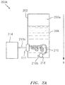
- FIG. 2A illustrates a system 200A in accordance with aspects of this disclosure.
- Superimposed in FIG. 2A is an axis 'g', where the direction of the axis is shown with respect to the Earth's gravitational field.
- the system 200A is shown under positive-G conditions.
- the system 200A may include a tank 202 that may store a quantity/volume of a lubricant 206, where the lubricant 206 may include oil. Due to the positive-G conditions, the lubricant 206 is shown as being biased towards the bottom of the tank 202 in FIG. 2A , such that a portion 202a of the tank 202 located towards the top of the tank 202 may be substantially devoid/free of lubricant.
- a conduit 210 may be used to supply at least a portion of the lubricant 206 in the tank 202 to one or more components of the engine.
- a first end 210a of the conduit 210 may emerge from an outlet 212 of the tank 202 and may be in fluid communication with a mechanism 214, e.g., a pump, where the pump may draw/pull at least a portion of the lubricant 206 from the tank 202 (e.g., the lubricant 206 may be conveyed from a second end/inlet 210b of the conduit 210 to the first end/outlet 210a of the conduit 210).
- the tank 202 may be pressurized in order to encourage a flow of lubricant out of the tank 202 (e.g., from the second end 210b of the conduit 210 towards the first end 210a of the conduit 210).
- operation of an FDGS 602 may serve as the mechanism 214 by which the fluid is drawn/pulled from the tank 202.
- the outlet 212 of the tank 202 is shown as fluidly coupled to the FDGS 602.
- the FDGS 602 may receive/consume at least a portion of the fluid provided from the tank 202 and may return (via an output/outlet 612 of the FDGS) at least a portion of the fluid to an inlet 622 of the tank 202.
- a complete fluid circuit may be established between the tank 202 and the FDGS 602.
- FIG. 6 shows the fluid circuit incorporating the tank 202 and the FDGS 602
- the fluid circuit may include additional components/devices.
- the aforementioned '661 publication describes and illustrates such additional components.
- the second end 210b of the conduit 210 may be positioned within/immersed in the lubricant 206 within the tank 202 in order to ensure that a supply of lubricant is available to, e.g., the mechanism 214.
- a density of the conduit 210 (or at least a density of the conduit 210 coinciding with the second end 210b) may be selected to be greater than or equal to a density of the lubricant 206 so that the second end 210b is positioned at the bottom of the tank 202 or immersed in the lubricant 206 in FIG. 2A .
- a density of the conduit 210/second end 210b may be selected to be up to twenty times greater than a density of the lubricant 206. In some embodiments, a ratio of the density of the conduit 210/second end 210b to a density of the lubricant 206 may be selected to be within a range of: (1) equal to or greater than one and (2) less than or equal to twenty.
- a mass 218 may optionally be included at/proximate the end 210b of the conduit 210.
- the mass 218 may be included in embodiments where, e.g., a density of the conduit 210 is less than a density of the lubricant 206.
- the density of the conduit 210 and the mass 218 in a region coinciding with the end 210b may be greater than or equal to a density of the lubricant 206. While described separately, the mass 218 may be included/integral with the conduit 210.
- the mass 218 may be coupled to the conduit 210 using one or more attachment techniques, such as for example using an adhesive, using a fastener (e.g., a bolt and a nut), welding, brazing, bonding, etc.
- a fastener e.g., a bolt and a nut
- the system 200A is shown during positive-G conditions.
- the system 200B of FIG. 2B (where the system 200B may structurally coincide with the system 200A of FIG. 2A ) is shown during negative-G conditions (relative to the Earth's gravitational field 'g').
- the lubricant 206, the end 210b, and the mass 218 are shown as being biased towards the top of the tank 202 in FIG. 2B , such that a portion 202b of the tank 202 located towards the bottom of the tank 202 may be substantially devoid/free of lubricant.
- the end 210b may be positioned within/immersed in the lubricant 206 within the tank 202 in both FIGS. 2A and 2B .
- the length/span of the conduit 210 may be selected to enable the end 210b/mass 218 to substantially travel the entire length (measured top-to-bottom or bottom-to-top in FIGS. 2A-2B ) of the tank 202, as well as reach the furthest corners of the tank (the right-most corners, bottom and top, in FIGS. 2A and 2B , given that the end 210a is shown on the left-most end of the tank 202 in FIGS. 2A and 2B ).
- the mass 218 may include a core 318a contained within a shell 318b.
- the core 318a may be made of a first material (e.g., a metal) and the shell 318b may be made of a second material (e.g., an elastomer), the second material being different from the first material.
- the shell 318b may help to protect the structural integrity of the core 318a and/or the tank 202 (see FIGS. 2A-2B ) in the event that the mass 218 contacts the tank 202.
- the shell 318b may absorb/dissipate any energy associated with the mass 218 impacting a wall/perimeter of the tank 202.
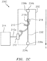
- the system 200C may incorporate many of the same components/devices described above in relation to the systems 200A and 200B of FIGS. 2A and 2B , respectively.
- the system 200C is shown as including a pole/post 232.
- the pole 232 may be coupled to the tank 202 at a first (distal) end 234a and at a second (distal) end 234b as shown in FIG. 2C .
- the mass 218 may be coupled to the pole 232, such that movement of the mass 218 may be limited to movement along a length/span of the pole 232 (e.g., lateral movement of the mass 218 within the tank 202 may be substantially prohibited/precluded).
- the tank 202/pole 232 may be fitted with a first stop 238a proximate the first end 234a.
- the tank 202/pole 232 may be fitted with a second stop 238b proximate the second end 234b.
- the stops 238a and 238b may take one or more forms, such as a bolt and nut, an instance of an elastomeric material, etc.
- the stops 238a and 238b may prevent the mass 218 from contacting the walls/perimeter of the tank 202 as the mass 218 moves along the pole 232 (where such mass 218 movement may be based on a change in gravitational conditions, e.g., a change from positive-G conditions to negative-G conditions or vice versa).
- the conduit 210 may include a flexible conduit 402.
- the conduit 402 may be radially inside an optional protective layer 404.
- the layer 404 may take the form of another conduit (e.g., a conduit in addition to the conduit 402), such that the conduit 210 may be configured as a coaxial conduit/tube (e.g., the conduit 210 may be arranged as a tube-within-a-tube).
- the layer 404 may contain any lubricant that may escape from the inner conduit 402; this can help to prevent a leak of lubricant in regions outside of the tank 202 (see FIGS. 2A-2C ). While the conduit 210 is shown includes two conduits/layers 402 and 404, any number of sub-conduits or layers may be included in some embodiments.
- the conduit 402 may be manufactured from an organic polymer.
- the organic polymer may be capable of withstanding temperatures up to hundreds of degrees Celsius, e.g., 121°C without being degraded or solubilized by lubricant or by by-products of lubricant degradation.
- the organic polymer may have an elastic modulus of about 10 5 to 10 6 Pascals at a temperature of, e.g., 65 to 121°C.
- the organic polymers used in the conduit 402 may have a glass transition temperature that is greater than 65°C and a melting point that is greater than 121°C.
- the glass transition temperature of the organic polymer is about 65°C to 121°C, while the melting point of the organic polymer is greater than 121°C to 232°C.
- Organic polymers used in the conduit 402 can be selected from a wide variety of thermoplastic polymers, blends of thermoplastic polymers, thermosetting polymers, or blends of thermoplastic polymers with thermosetting polymers.
- the organic polymer may also be a blend of polymers, copolymers, terpolymers, or combinations comprising at least one of the foregoing organic polymers.
- the organic polymer can also be an oligomer, a homopolymer, a copolymer, a block copolymer, an alternating block copolymer, a random polymer, a random copolymer, a random block copolymer, a graft copolymer, a star block copolymer, a dendrimer, or the like, or a combination comprising at last one of the foregoing organic polymers.
- organic polymers examples include polyacetals, polyolefins, polyacrylics, polycarbonates, polystyrenes, polyesters, polyamides, polyamideimides, polyarylates, polyarylsulfones, polyethersulfones, polyphenylene sulfides, polyvinyl chlorides, polysulfones, polyimides, polyetherimides, polytetrafluoroethylenes, polyetherketones, polyether etherketones, polyether ketone ketones, polybenzoxazoles, polyphthalides, polyacetals, polyanhydrides, polyvinyl ethers, polyvinyl thioethers, polyvinyl alcohols, polyvinyl ketones, polyvinyl halides, polyvinyl nitriles, polyvinyl esters, polysulfonates, polysulfides, polythioesters, polysulfones, polysulfonamides,
- thermosetting polymers suitable for use in the conduit 402 include epoxy polymers, unsaturated polyester polymers, polyimide polymers, bismaleimide polymers, bismaleimide triazine polymers, cyanate ester polymers, vinyl polymers, benzoxazine polymers, benzocyclobutene polymers, acrylics, alkyds, phenol-formaldehyde polymers, novolacs, resoles, melamine-formaldehyde polymers, urea-formaldehyde polymers, hydroxymethylfurans, isocyanates, diallyl phthalate, triallyl cyanurate, triallyl isocyanurate, unsaturated polyesterimides, or the like, or a combination thereof.
- a thermosetting polymer may be an elastomer.
- Suitable elastomers are polybutadienes, polyisoprenes, styrene-butadiene rubber, poly(styrene)-block-poly(butadiene), poly(acrylonitrile)-block-poly(styrene)-block-poly(butadiene) (ABS), polychloroprenes, epichlorohydrin rubber, polyacrylic rubber, silicone elastomers (polysiloxanes), fluorosilicone elastomers, fluoroelastomers, perfluoroelastomers, polyether block amides (PEBA), chlorosulfonated polyethylene, ethylene propylene diene rubber (EPR), ethylene-vinyl acetate elastomers, or the like, or a combination thereof.
- PEBA polyether block amides
- EPR ethylene propylene diene rubber
- EPR ethylene
- thermoplastic polymers examples include acrylonitrile-butadiene-styrene/nylon, polycarbonate/acrylonitrile-butadiene-styrene, acrylonitrile butadiene styrene/polyvinyl chloride, polyphenylene ether/polystyrene, polyphenylene ether/nylon, polysulfone/acrylonitrile-butadiene-styrene, polycarbonate/thermoplastic urethane, polycarbonate/polyethylene terephthalate, polycarbonate/polybutylene terephthalate, thermoplastic elastomer alloys, nylon/elastomers, polyester/elastomers, polyethylene terephthalate/polybutylene terephthalate, acetal/elastomer, styrene-maleicanhydride/acrylonitrile-butadiene-styrene, polyether etherketone/polyethersulf
- the conduit 402 is manufactured from an elastomer.
- elastomers are silicone elastomers, fluorosilicone elastomers, fluoroelastomers, perfluoroelastomers, or a combination thereof.
- the layer 404 may comprise a single or multiple layers of one or more of a metal, a ceramic, or a composite.
- the layers may be thin enough or ductile enough to permit the conduit 402 to have the desired flexibility (e.g., flexibility in an amount greater than a threshold).
- Exemplary metals that may be used for the layer 404 include iron, titanium, aluminum, cobalt, nickel, silver, or the like, or a combination thereof.
- Exemplary composite that may be used for the layer 404 include organic matrix composites, metal matrix composites, ceramic matrix composites, or the like, or a combination thereof.
- FIGS. 2A-2C While some of the examples described above in relation to, e.g., FIGS. 2A-2C related to the existence of positive-G conditions or negative-G conditions, aspects of the disclosure may be applied in relation to zero-G conditions.
- the gravitational condition may spend substantially little time at zero-G conditions in transitioning from, e.g., a positive-G condition to a negative-G condition.
- FIG. 5 depicts an exemplary plot 500 of the variation of the gravitational condition on the vertical axis versus time on the horizontal axis, where the zero-G condition is shown as occurring at times 502a and 502b.
- operation in one or more conditions may persist for extended durations/periods of time.
- Technical effects and benefits of this disclosure include an ability to provide at least a threshold amount of a lubricant to one or more components of an engine.
- the lubricant may be reliably provided during reduced-G conditions, thereby helping to ensure continued operability of the component(s).
- At least a portion/region of a conduit may move substantially in unison with a fluid stored in a tank during changing gravitational conditions.
- aspects of the disclosure may be used to provide any type of fluid (e.g., any type of liquid) to the component.
- fluids may include hydraulic fluid, fuel (e.g., gasoline), refrigerant, etc.
Landscapes
- Engineering & Computer Science (AREA)
- General Engineering & Computer Science (AREA)
- Mechanical Engineering (AREA)
- Aviation & Aerospace Engineering (AREA)
- Structures Of Non-Positive Displacement Pumps (AREA)
- General Details Of Gearings (AREA)
Abstract
Description
- Gas turbine engines, such as those which power aircraft and industrial equipment, employ a compressor to compress air that is drawn into the engine and a turbine to capture energy associated with the combustion of a fuel-air mixture. At least on an aircraft, an engine may assume various positions/attitudes and may be subject to various forces over the operational lifetime of the engine.
- United States patent application publication number
2014/0076661 A1 (hereinafter referred to as the '661 publication) describes systems/architectures for providing lubricant to various components (e.g., journal pins, gears, etc.) of the engine, regardless of the environmental conditions in which the engine is operating. As described in the '661 publication, it may be desirable to ensure that those components are not starved of lubricant (e.g., that the components/sub-systems receive lubricant in an amount that is greater than a threshold) during reduced-G conditions in which acceleration due to the Earth's gravitational field is partially or entirely counteracted by aircraft maneuvers and/or orientation, such as for example during free-fall brought on by a loss of engine power. Reduced-G conditions include, for example, negative gravity (also referred to herein as negative-G), zero gravity (also referred to herein as zero-G), and positive gravity (also referred to herein as positive-G) conditions materially less than about 9.8 meters/sec/sec. Failure to ensure that the threshold supply of lubricant is provided to a component during, e.g., reduced-G conditions may render the component inoperable. Thus, what is needed are improved techniques for providing at least a threshold amount of lubricant to one or more components of the engine, inclusive of when the engine is operating in reduced-G conditions. - The following presents a simplified summary in order to provide a basic understanding of some aspects of the disclosure. The summary is not an extensive overview of the disclosure. It is neither intended to identify key or critical elements of the disclosure nor to delineate the scope of the disclosure. The following summary merely presents some concepts of the disclosure in a simplified form as a prelude to the description below.
- Aspects of the disclosure are directed to a system comprising: a tank that stores a fluid, and a conduit that includes a first end and a second end, where the conduit is configured to convey at least a portion of the fluid stored in the tank from the second end of the conduit to the first end of the conduit, where a first end region of the conduit coinciding with the second end of the conduit has a first end region density and the fluid has a fluid density, where the first end region density is greater than or equal to the fluid density such that the first end region of the conduit remains immersed in the fluid stored in the tank when the fluid in the tank is under negative gravity conditions.
- In some embodiments, the fluid includes at least one of hydraulic fluid, fuel, or refrigerant.
- In some embodiments, the fluid includes a lubricant.
- In some embodiments, the first end of the conduit is in fluid communication with a mechanism that draws at least a portion of the lubricant from the tank.
- In some embodiments, the system further comprises a mass coupled to the second end of the conduit.
- In some embodiments, the first end region density is a collective density of a density of the conduit at the second end of the conduit and a density of the mass.
- In some embodiments, the system further comprises a pole coupled to the mass, where the mass is limited to movement along a span of the pole.
- In some embodiments, a first end of the pole is coupled to a first end of the tank, and where a second end of the pole is coupled to a second end of the tank.
- In some embodiments, at least one of the first end of the pole or the first end of the tank is fitted with a first stop, and where at least one of the second end of the pole or the second end of the tank is fitted with a second stop.
- In some embodiments, the first stop includes at least one of a bolt and nut or an instance of an elastomeric material.
- In some embodiments, the mass includes a core contained within a shell, where the core is made of a first material and the shell is made of a second material, and where the second material is different from the first material.
- In some embodiments, the core is made of metal and where the shell is made of an elastomer.
- In some embodiments, the mass is substantially shaped as a sphere.
- In some embodiments, the system further comprises a pump coupled to the first end of the conduit.
- In some embodiments, the tank is pressurized to convey the fluid from the second end of the conduit to the first end of the conduit.
- In some embodiments, the system further comprises a fan drive gear system of a gas turbine engine fluidly coupled to the first end of the conduit to receive at least a portion of the fluid conveyed by the conduit, where the fan drive gear system returns at least a portion of the fluid to a tank inlet of the tank.
- In some embodiments, the conduit includes a flexible conduit radially inside a protective layer.
- In some embodiments, the protective layer is an additional conduit, and where the flexible conduit is disposed within the additional conduit such that the conduit is arranged as a tube-within-a-tube.
- Aspects of the disclosure are directed to a system comprising: a tank that stores a fluid and includes a tank outlet, and a fluid conduit that includes a conduit inlet at a distal end of the fluid conduit and a conduit outlet at a proximate end of the fluid conduit, where the conduit outlet is located at or proximate the tank outlet, and where the conduit inlet is immersed in the fluid within the tank and the fluid conduit provides fluid flow from the conduit inlet to the conduit outlet, where a first end region of the fluid conduit that extends towards the distal end has a first end region density, where the first end region density is greater than or equal to a fluid density of the fluid such that the conduit inlet remains immersed in the fluid stored in the tank when the fluid in the tank is under negative gravity conditions.
- In some embodiments, the first end region density is greater than or equal to the fluid density such that the conduit inlet remains immersed in the fluid stored in the tank when the fluid in the tank is under positive gravity conditions, and the conduit inlet moves substantially in unison with the fluid in the tank when the fluid in the tank is subject to a change in gravitational conditions.
- The present disclosure is illustrated by way of example and not limited in the accompanying figures in which like reference numerals indicate similar elements. The drawing figures are not necessarily drawn to scale unless specifically indicated otherwise.
-
FIG. 1 is a side cutaway illustration of a geared turbine engine. -
FIG. 2A illustrates a system for providing lubricant, where the system is shown during positive-G conditions. -
FIG. 2B illustrates the system ofFIG. 2A during negative-G conditions. -
FIG. 2C illustrates a system for providing lubricant, where the system includes a pole to constrain a movement of a mass. -
FIG. 3 illustrates a mass that may be coupled to a conduit in accordance with aspects of this disclosure. -
FIG. 4 illustrates a conduit in accordance with aspects of this disclosure. -
FIG. 5 illustrates a plot of gravitational conditions versus time in accordance with an exemplary embodiment. -
FIG. 6 illustrates a fluid circuit incorporating a fan drive gear system (FDGS) and a tank in accordance with aspects of this disclosure. - It is noted that various connections are set forth between elements in the following description and in the drawings (the contents of which are incorporated in this specification by way of reference). It is noted that these connections are general and, unless specified otherwise, may be direct or indirect and that this specification is not intended to be limiting in this respect. A coupling between two or more entities may refer to a direct connection or an indirect connection. An indirect connection may incorporate one or more intervening entities or a space/gap between the entities that are being coupled to one another.
- Aspects of the disclosure are directed to apparatuses, systems, and methods associated with an engine. In some embodiments, a conduit having an associated mass may be provided. The conduit may be at least partially located in a tank. A density associated with the conduit may be equal to or greater than a density of a fluid that is present in the tank, such that at least a portion of the conduit (e.g., an end of the conduit) may be positioned/immersed in the fluid within the tank.
- Aspects of the disclosure may be applied in connection with a gas turbine engine.
FIG. 1 is a side cutaway illustration of a gearedturbine engine 10. Thisturbine engine 10 extends along anaxial centerline 12 between anupstream airflow inlet 14 and adownstream airflow exhaust 16. Theturbine engine 10 includes afan section 18, acompressor section 19, acombustor section 20 and aturbine section 21. Thecompressor section 19 includes a low pressure compressor (LPC)section 19A and a high pressure compressor (HPC)section 19B. Theturbine section 21 includes a high pressure turbine (HPT)section 21A and a low pressure turbine (LPT)section 21B. - The engine sections 18-21 are arranged sequentially along the
centerline 12 within anengine housing 22. Each of the engine sections 18-19B, 21A and 21B includes a respective rotor 24-28. Each of these rotors 24-28 includes a plurality of rotor blades arranged circumferentially around and connected to one or more respective rotor disks. The rotor blades, for example, may be formed integral with or mechanically fastened, welded, brazed, adhered and/or otherwise attached to the respective rotor disk(s). - The
fan rotor 24 is connected to agear train 30, for example, through afan shaft 32. Thegear train 30 and theLPC rotor 25 are connected to and driven by theLPT rotor 28 through alow speed shaft 33. TheHPC rotor 26 is connected to and driven by theHPT rotor 27 through ahigh speed shaft 34. The shafts 32-34 are rotatably supported by a plurality ofbearings 36; e.g., rolling element and/or thrust bearings. Each of thesebearings 36 is connected to theengine housing 22 by at least one stationary structure such as, for example, an annular support strut. - As one skilled in the art would appreciate, in some embodiments a fan drive gear system (FDGS), which may be incorporated as part of the
gear train 30, may be used to separate the rotation of thefan rotor 24 from the rotation of therotor 25 of the lowpressure compressor section 19A and therotor 28 of the lowpressure turbine section 21B. For example, such an FDGS may allow thefan rotor 24 to rotate at a different (e.g., slower) speed relative to therotors - During operation, air enters the
turbine engine 10 through theairflow inlet 14, and is directed through thefan section 18 and into acore gas path 38 and abypass gas path 40. The air within thecore gas path 38 may be referred to as "core air". The air within thebypass gas path 40 may be referred to as "bypass air". The core air is directed through the engine sections 19-21, and exits theturbine engine 10 through theairflow exhaust 16 to provide forward engine thrust. Within thecombustor section 20, fuel is injected into acombustion chamber 42 and mixed with compressed core air. This fuel-core air mixture is ignited to power theturbine engine 10. The bypass air is directed through thebypass gas path 40 and out of theturbine engine 10 through abypass nozzle 44 to provide additional forward engine thrust. This additional forward engine thrust may account for a majority (e.g., more than 70 percent) of total engine thrust. Alternatively, at least some of the bypass air may be directed out of theturbine engine 10 through a thrust reverser to provide reverse engine thrust. -
FIG. 1 represents one possible configuration for anengine 10. Aspects of the disclosure may be applied in connection with other environments, including additional configurations for gas turbine engines. Aspects of the disclosure may be applied in connection with non-geared engines. - As described above, occasionally an engine (e.g., the
engine 10 ofFIG. 1 ) may operate in reduced-G conditions. Such reduced-G conditions may be experienced during a flight on an aircraft. Some areas of the engine, such as the FDGS, may require a relatively non-interrupted supply of lubricant (e.g., may require lubricant in an amount greater than a threshold, potentially as measured over a predetermined period of time). -
FIG. 2A illustrates asystem 200A in accordance with aspects of this disclosure. Superimposed inFIG. 2A is an axis 'g', where the direction of the axis is shown with respect to the Earth's gravitational field. In particular, thesystem 200A is shown under positive-G conditions. - The
system 200A may include atank 202 that may store a quantity/volume of alubricant 206, where thelubricant 206 may include oil. Due to the positive-G conditions, thelubricant 206 is shown as being biased towards the bottom of thetank 202 inFIG. 2A , such that aportion 202a of thetank 202 located towards the top of thetank 202 may be substantially devoid/free of lubricant. - A
conduit 210 may be used to supply at least a portion of thelubricant 206 in thetank 202 to one or more components of the engine. For example, afirst end 210a of theconduit 210 may emerge from anoutlet 212 of thetank 202 and may be in fluid communication with amechanism 214, e.g., a pump, where the pump may draw/pull at least a portion of thelubricant 206 from the tank 202 (e.g., thelubricant 206 may be conveyed from a second end/inlet 210b of theconduit 210 to the first end/outlet 210a of the conduit 210). In some embodiments, thetank 202 may be pressurized in order to encourage a flow of lubricant out of the tank 202 (e.g., from thesecond end 210b of theconduit 210 towards thefirst end 210a of the conduit 210). - In some embodiments (see
FIG. 6 ), operation of an FDGS 602 (e.g., a rotation ofgears 608 included in the FDGS 602) may serve as themechanism 214 by which the fluid is drawn/pulled from thetank 202. InFIG. 6 , theoutlet 212 of thetank 202 is shown as fluidly coupled to theFDGS 602. TheFDGS 602 may receive/consume at least a portion of the fluid provided from thetank 202 and may return (via an output/outlet 612 of the FDGS) at least a portion of the fluid to aninlet 622 of thetank 202. In this respect, a complete fluid circuit may be established between thetank 202 and theFDGS 602. WhileFIG. 6 shows the fluid circuit incorporating thetank 202 and theFDGS 602, one skilled in the art would appreciate that the fluid circuit may include additional components/devices. For example, the aforementioned '661 publication describes and illustrates such additional components. - Referring back to
FIG. 2A , thesecond end 210b of theconduit 210 may be positioned within/immersed in thelubricant 206 within thetank 202 in order to ensure that a supply of lubricant is available to, e.g., themechanism 214. A density of the conduit 210 (or at least a density of theconduit 210 coinciding with thesecond end 210b) may be selected to be greater than or equal to a density of thelubricant 206 so that thesecond end 210b is positioned at the bottom of thetank 202 or immersed in thelubricant 206 inFIG. 2A . In some embodiments, a density of theconduit 210/second end 210b may be selected to be up to twenty times greater than a density of thelubricant 206. In some embodiments, a ratio of the density of theconduit 210/second end 210b to a density of thelubricant 206 may be selected to be within a range of: (1) equal to or greater than one and (2) less than or equal to twenty. - In some embodiments, a
mass 218 may optionally be included at/proximate theend 210b of theconduit 210. Themass 218 may be included in embodiments where, e.g., a density of theconduit 210 is less than a density of thelubricant 206. Collectively, the density of theconduit 210 and themass 218 in a region coinciding with theend 210b may be greater than or equal to a density of thelubricant 206. While described separately, themass 218 may be included/integral with theconduit 210. - While the
mass 218 is shown as assuming a (substantially) spherical shape, other shapes for themass 218 may be used in some embodiments. Themass 218 may be coupled to theconduit 210 using one or more attachment techniques, such as for example using an adhesive, using a fastener (e.g., a bolt and a nut), welding, brazing, bonding, etc. - As described above, the
system 200A is shown during positive-G conditions. In comparison, thesystem 200B ofFIG. 2B (where thesystem 200B may structurally coincide with thesystem 200A ofFIG. 2A ) is shown during negative-G conditions (relative to the Earth's gravitational field 'g'). In such negative-G conditions, thelubricant 206, theend 210b, and the mass 218 (to the extent that themass 218 is included in some embodiments) are shown as being biased towards the top of thetank 202 inFIG. 2B , such that aportion 202b of thetank 202 located towards the bottom of thetank 202 may be substantially devoid/free of lubricant. - As the relative densities of the conduit 210 (collectively with the
mass 218, to the extent that themass 218 is included) and thelubricant 206 do not change based on whether thesystem end 210b may be positioned within/immersed in thelubricant 206 within thetank 202 in bothFIGS. 2A and2B . The length/span of theconduit 210 may be selected to enable theend 210b/mass 218 to substantially travel the entire length (measured top-to-bottom or bottom-to-top inFIGS. 2A-2B ) of thetank 202, as well as reach the furthest corners of the tank (the right-most corners, bottom and top, inFIGS. 2A and2B , given that theend 210a is shown on the left-most end of thetank 202 inFIGS. 2A and2B ). - Referring to
FIG. 3 , in some embodiments themass 218 may include acore 318a contained within ashell 318b. Thecore 318a may be made of a first material (e.g., a metal) and theshell 318b may be made of a second material (e.g., an elastomer), the second material being different from the first material. Theshell 318b may help to protect the structural integrity of thecore 318a and/or the tank 202 (seeFIGS. 2A-2B ) in the event that the mass 218 contacts thetank 202. For example, theshell 318b may absorb/dissipate any energy associated with themass 218 impacting a wall/perimeter of thetank 202. - Referring to
FIG. 2C , asystem 200C is shown. Thesystem 200C may incorporate many of the same components/devices described above in relation to thesystems FIGS. 2A and2B , respectively. Thesystem 200C is shown as including a pole/post 232. Thepole 232 may be coupled to thetank 202 at a first (distal)end 234a and at a second (distal)end 234b as shown inFIG. 2C . Themass 218 may be coupled to thepole 232, such that movement of themass 218 may be limited to movement along a length/span of the pole 232 (e.g., lateral movement of themass 218 within thetank 202 may be substantially prohibited/precluded). - The
tank 202/pole 232 may be fitted with afirst stop 238a proximate thefirst end 234a. Thetank 202/pole 232 may be fitted with asecond stop 238b proximate thesecond end 234b. Thestops stops tank 202 as themass 218 moves along the pole 232 (wheresuch mass 218 movement may be based on a change in gravitational conditions, e.g., a change from positive-G conditions to negative-G conditions or vice versa). - Referring to
FIG. 4 , an exemplary embodiment of the conduit 210 (seeFIGS. 2A-2C ) is shown. Theconduit 210 may include aflexible conduit 402. Theconduit 402 may be radially inside an optionalprotective layer 404. In some embodiments, thelayer 404 may take the form of another conduit (e.g., a conduit in addition to the conduit 402), such that theconduit 210 may be configured as a coaxial conduit/tube (e.g., theconduit 210 may be arranged as a tube-within-a-tube). Thelayer 404 may contain any lubricant that may escape from theinner conduit 402; this can help to prevent a leak of lubricant in regions outside of the tank 202 (seeFIGS. 2A-2C ). While theconduit 210 is shown includes two conduits/layers - The
conduit 402 may be manufactured from an organic polymer. The organic polymer may be capable of withstanding temperatures up to hundreds of degrees Celsius, e.g., 121°C without being degraded or solubilized by lubricant or by by-products of lubricant degradation. In some embodiments, the organic polymer may have an elastic modulus of about 105 to 106 Pascals at a temperature of, e.g., 65 to 121°C. In some embodiments, the organic polymers used in theconduit 402 may have a glass transition temperature that is greater than 65°C and a melting point that is greater than 121°C. In an embodiment, the glass transition temperature of the organic polymer is about 65°C to 121°C, while the melting point of the organic polymer is greater than 121°C to 232°C. - Organic polymers used in the
conduit 402 can be selected from a wide variety of thermoplastic polymers, blends of thermoplastic polymers, thermosetting polymers, or blends of thermoplastic polymers with thermosetting polymers. The organic polymer may also be a blend of polymers, copolymers, terpolymers, or combinations comprising at least one of the foregoing organic polymers. The organic polymer can also be an oligomer, a homopolymer, a copolymer, a block copolymer, an alternating block copolymer, a random polymer, a random copolymer, a random block copolymer, a graft copolymer, a star block copolymer, a dendrimer, or the like, or a combination comprising at last one of the foregoing organic polymers. - Examples of the organic polymers that can be used in the
conduit 402 are polyacetals, polyolefins, polyacrylics, polycarbonates, polystyrenes, polyesters, polyamides, polyamideimides, polyarylates, polyarylsulfones, polyethersulfones, polyphenylene sulfides, polyvinyl chlorides, polysulfones, polyimides, polyetherimides, polytetrafluoroethylenes, polyetherketones, polyether etherketones, polyether ketone ketones, polybenzoxazoles, polyphthalides, polyacetals, polyanhydrides, polyvinyl ethers, polyvinyl thioethers, polyvinyl alcohols, polyvinyl ketones, polyvinyl halides, polyvinyl nitriles, polyvinyl esters, polysulfonates, polysulfides, polythioesters, polysulfones, polysulfonamides, polyureas, polyphosphazenes, polysilazanes, styrene acrylonitrile, acrylonitrile-butadiene-styrene (ABS), polyethylene terephthalate, polybutylene terephthalate, polyurethane, polytetrafluoroethylene, fluorinated ethylene propylene, perfluoroalkoxyethylene, polychlorotrifluoroethylene, polyvinylidene fluoride, or the like, or a combination thereof. - Examples of thermosetting polymers suitable for use in the
conduit 402 include epoxy polymers, unsaturated polyester polymers, polyimide polymers, bismaleimide polymers, bismaleimide triazine polymers, cyanate ester polymers, vinyl polymers, benzoxazine polymers, benzocyclobutene polymers, acrylics, alkyds, phenol-formaldehyde polymers, novolacs, resoles, melamine-formaldehyde polymers, urea-formaldehyde polymers, hydroxymethylfurans, isocyanates, diallyl phthalate, triallyl cyanurate, triallyl isocyanurate, unsaturated polyesterimides, or the like, or a combination thereof. - In an embodiment, a thermosetting polymer may be an elastomer. Suitable elastomers are polybutadienes, polyisoprenes, styrene-butadiene rubber, poly(styrene)-block-poly(butadiene), poly(acrylonitrile)-block-poly(styrene)-block-poly(butadiene) (ABS), polychloroprenes, epichlorohydrin rubber, polyacrylic rubber, silicone elastomers (polysiloxanes), fluorosilicone elastomers, fluoroelastomers, perfluoroelastomers, polyether block amides (PEBA), chlorosulfonated polyethylene, ethylene propylene diene rubber (EPR), ethylene-vinyl acetate elastomers, or the like, or a combination thereof.
- Examples of blends of thermoplastic polymers include acrylonitrile-butadiene-styrene/nylon, polycarbonate/acrylonitrile-butadiene-styrene, acrylonitrile butadiene styrene/polyvinyl chloride, polyphenylene ether/polystyrene, polyphenylene ether/nylon, polysulfone/acrylonitrile-butadiene-styrene, polycarbonate/thermoplastic urethane, polycarbonate/polyethylene terephthalate, polycarbonate/polybutylene terephthalate, thermoplastic elastomer alloys, nylon/elastomers, polyester/elastomers, polyethylene terephthalate/polybutylene terephthalate, acetal/elastomer, styrene-maleicanhydride/acrylonitrile-butadiene-styrene, polyether etherketone/polyethersulfone, polyether etherketone/polyetherimide polyethylene/nylon, polyethylene/polyacetal, or the like.
- In some embodiments, the
conduit 402 is manufactured from an elastomer. Exemplary elastomers are silicone elastomers, fluorosilicone elastomers, fluoroelastomers, perfluoroelastomers, or a combination thereof. - The
layer 404 may comprise a single or multiple layers of one or more of a metal, a ceramic, or a composite. The layers may be thin enough or ductile enough to permit theconduit 402 to have the desired flexibility (e.g., flexibility in an amount greater than a threshold). Exemplary metals that may be used for thelayer 404 include iron, titanium, aluminum, cobalt, nickel, silver, or the like, or a combination thereof. Exemplary composite that may be used for thelayer 404 include organic matrix composites, metal matrix composites, ceramic matrix composites, or the like, or a combination thereof. - While some of the examples described above in relation to, e.g.,
FIGS. 2A-2C related to the existence of positive-G conditions or negative-G conditions, aspects of the disclosure may be applied in relation to zero-G conditions. One skilled in the art would appreciate that, as a practical matter, the gravitational condition may spend substantially little time at zero-G conditions in transitioning from, e.g., a positive-G condition to a negative-G condition. For example,FIG. 5 depicts anexemplary plot 500 of the variation of the gravitational condition on the vertical axis versus time on the horizontal axis, where the zero-G condition is shown as occurring attimes - Technical effects and benefits of this disclosure include an ability to provide at least a threshold amount of a lubricant to one or more components of an engine. The lubricant may be reliably provided during reduced-G conditions, thereby helping to ensure continued operability of the component(s). At least a portion/region of a conduit may move substantially in unison with a fluid stored in a tank during changing gravitational conditions.
- While some of the examples described herein related to providing a lubricant to a component, aspects of the disclosure may be used to provide any type of fluid (e.g., any type of liquid) to the component. Examples of such fluids may include hydraulic fluid, fuel (e.g., gasoline), refrigerant, etc.
- Aspects of the disclosure have been described in terms of illustrative embodiments thereof. Numerous other embodiments, modifications, and variations within the scope of the appended claims will occur to persons of ordinary skill in the art from a review of this disclosure. For example, one of ordinary skill in the art will appreciate that the steps described in conjunction with the illustrative figures may be performed in other than the recited order, and that one or more steps illustrated may be optional in accordance with aspects of the disclosure. One or more features described in connection with a first embodiment may be combined with one or more features of one or more additional embodiments.
Claims (15)
- A system (200A, B, C) comprising:a tank (202) that stores a fluid (206); anda conduit (210) that includes a first end (210a) and a second end (210b),wherein the conduit (210) is configured to convey at least a portion of the fluid (206) stored in the tank (202) from the second end (210b) of the conduit (210) to the first end (210a) of the conduit (210),wherein a first end region of the conduit (210) coinciding with the second end (210b) of the conduit (210) has a first end region density and the fluid (206) has a fluid density,wherein the first end region density is greater than or equal to the fluid density such that the first end region of the conduit (210) remains immersed in the fluid (206) stored in the tank (202) when the fluid (206) in the tank (202) is under negative gravity conditions.
- The system of claim 1, wherein:the fluid (206) includes at least one of hydraulic fluid, fuel, or refrigerant; and/orthe fluid (206) includes a lubricant.
- The system of claim 1 or 2, wherein the first end (210a) of the conduit (210) is in fluid communication with a mechanism (214) that draws at least a portion of lubricant (206) from the tank (202).
- The system of any preceding claim, further comprising a mass (218) coupled to the second end (210b) of the conduit (210).
- The system of claim 4, wherein the first end region density is a collective density of a density of the conduit (210) at the second end (210b) of the conduit (210) and a density of the mass (218).
- The system of claim 4 or 5, further comprising a pole (232) coupled to the mass (218), wherein the mass (218) is limited to movement along a span of the pole (232).
- The system of claim 6, wherein a first end (234a) of the pole (232) is coupled to a first end of the tank (202), and wherein a second end (234b) of the pole (232) is coupled to a second end of the tank (202).
- The system of claim 7, wherein at least one of the first end (234a) of the pole (232) or the first end of the tank (202) is fitted with a first stop (238a), and wherein at least one of the second end (234b) of the pole (232) or the second end of the tank (202) is fitted with a second stop (238b), wherein, optionally, the first stop (238a) includes at least one of a bolt and nut or an instance of an elastomeric material.
- The system of any of claims 4 to 8, wherein the mass (218) includes a core (318a) contained within a shell (318b), wherein the core (318a) is made of a first material and the shell (318b) is made of a second material, and the second material is different from the first material, wherein, optionally, the core (318a) is made of metal and the shell (318b) is made of an elastomer.
- The system of any of claims 4 to 9, wherein the mass (218) is substantially shaped as a sphere.
- The system of any preceding claim, further comprising a pump (214) coupled to the first end (210a) of the conduit (210).
- The system of any preceding claim, wherein the tank (202) is pressurized to convey the fluid (206) from the second end (210b) of the conduit (210) to the first end (210a) of the conduit (210).
- The system of any preceding claim, further comprising a fan drive gear system (214; 602) of a gas turbine engine (10) fluidly coupled to the first end (210a) of the conduit (210) to receive at least a portion of the fluid (206) conveyed by the conduit (210), wherein the fan drive gear system (214; 602) returns at least a portion of the fluid (206) to a tank inlet (622) of the tank (202).
- The system of any preceding claim, wherein the conduit (210) includes a flexible conduit (402) radially inside a protective layer (404). optionally, wherein the protective layer (404) is an additional conduit (404), and wherein the flexible conduit (402) is disposed within the additional conduit (404) such that the conduit (210) is arranged as a tube-within-a-tube.
- A system (200A; B; C) comprising:a tank (202) that stores a fluid (206) and includes a tank outlet (212); anda fluid conduit (210) that includes a conduit inlet (210b) at a distal end (210b) of the fluid conduit (210) and a conduit (210a) outlet at a proximate end (210a) of the fluid conduit (210), wherein the conduit outlet (210a) is located at or proximate the tank outlet (212), and wherein the conduit inlet (210b) is immersed in the fluid (206) within the tank (202) and the fluid conduit (210) provides fluid flow from the conduit inlet (210b) to the conduit outlet (210a);wherein a first end region of the fluid conduit (210) that extends towards the distal end (210b) has a first end region density, wherein the first end region density is greater than or equal to a fluid density of the fluid (206) such that the conduit inlet (210b) remains immersed in the fluid (206) stored in the tank (202) when the fluid (206) in the tank (202) is under negative gravity conditions, wherein, optionally the first end region density is greater than or equal to the fluid density such that the conduit inlet (210b) remains immersed in the fluid (206) stored in the tank (202) when the fluid (206) in the tank (202) is under positive gravity conditions, and wherein the conduit inlet (210b) moves substantially in unison with the fluid (206) in the tank (202) when the fluid (206) in the tank (202) is subject to a change in gravitational conditions.
Applications Claiming Priority (1)
| Application Number | Priority Date | Filing Date | Title |
|---|---|---|---|
| US15/350,754 US20180135741A1 (en) | 2016-11-14 | 2016-11-14 | Fluid supply over range of gravitational conditions |
Publications (2)
| Publication Number | Publication Date |
|---|---|
| EP3321481A1 true EP3321481A1 (en) | 2018-05-16 |
| EP3321481B1 EP3321481B1 (en) | 2020-03-04 |
Family
ID=60331423
Family Applications (1)
| Application Number | Title | Priority Date | Filing Date |
|---|---|---|---|
| EP17201263.5A Active EP3321481B1 (en) | 2016-11-14 | 2017-11-13 | Fluid supply over range of gravitational conditions |
Country Status (2)
| Country | Link |
|---|---|
| US (2) | US20180135741A1 (en) |
| EP (1) | EP3321481B1 (en) |
Families Citing this family (2)
| Publication number | Priority date | Publication date | Assignee | Title |
|---|---|---|---|---|
| US10787930B2 (en) * | 2018-03-23 | 2020-09-29 | Raytheon Technologies Corporation | Windmill lubrication gear train for lubricant system in a geared gas turbine engine |
| US12259036B2 (en) | 2018-04-20 | 2025-03-25 | Rtx Corporation | Electric motor driven auxiliary oil system for geared gas turbine engine |
Citations (9)
| Publication number | Priority date | Publication date | Assignee | Title |
|---|---|---|---|---|
| US3022053A (en) * | 1959-07-13 | 1962-02-20 | William M Hoyt | Emergency fuel feeding system for airplanes |
| JPS5161444U (en) * | 1974-11-07 | 1976-05-14 | ||
| JPS53152033U (en) * | 1977-05-06 | 1978-11-30 | ||
| JPH04109011A (en) * | 1990-08-29 | 1992-04-10 | Atsugi Unisia Corp | Oil strainer device |
| DE19530256C1 (en) * | 1995-08-17 | 1997-01-23 | Webasto Thermosysteme Gmbh | Suction device to extract fuel from tank |
| EP1593539A1 (en) * | 2004-05-07 | 2005-11-09 | Ford Global Technologies, LLC, A subsidary of Ford Motor Company | Floating suction embodiment for compensating the oil level |
| US20090013959A1 (en) * | 2007-07-14 | 2009-01-15 | Szu Liang Lin | lubrication system for an engine |
| US20110067659A1 (en) * | 2009-09-24 | 2011-03-24 | Makita Corporation | Lubrication system for portable four-stroke engine |
| US20140076661A1 (en) | 2012-09-19 | 2014-03-20 | United Technologies Corporation | Lubrication system having porous feature |
Family Cites Families (16)
| Publication number | Priority date | Publication date | Assignee | Title |
|---|---|---|---|---|
| US1871055A (en) * | 1930-06-19 | 1932-08-09 | Pratt & Whitney Aircraft Compa | Liquid supplying means for aircraft engines |
| FR1565071A (en) * | 1968-04-25 | 1969-04-25 | ||
| US4273272A (en) * | 1979-11-13 | 1981-06-16 | William B. Anderson | Liquid dispenser |
| US5195664A (en) * | 1992-04-03 | 1993-03-23 | Steven Rhea | All directional fluid pick-up |
| US6213079B1 (en) * | 1998-06-03 | 2001-04-10 | Fuji Robin Kabushiki Kaisha | Lubricating apparatus for four-cycle engines |
| US6394319B1 (en) * | 2000-11-21 | 2002-05-28 | Robert Pucillo | Flexible liquid feeding assembly |
| US7240810B2 (en) * | 2002-11-08 | 2007-07-10 | S.C. Johnson & Son, Inc. | Flexible supply tube with weighting mechanism for use in spray bottles |
| US7246755B2 (en) * | 2003-12-18 | 2007-07-24 | Cepia, Llc | Power sprayer |
| US7648083B2 (en) * | 2003-12-18 | 2010-01-19 | S.C. Johnson & Son, Inc. | Power sprayer |
| US8585538B2 (en) * | 2006-07-05 | 2013-11-19 | United Technologies Corporation | Coupling system for a star gear train in a gas turbine engine |
| US8695563B2 (en) * | 2009-09-24 | 2014-04-15 | Makita Corporation | Lubrication system for four-stroke engine |
| US9410448B2 (en) * | 2012-05-31 | 2016-08-09 | United Technologies Corporation | Auxiliary oil system for negative gravity event |
| US20140158720A1 (en) * | 2012-12-12 | 2014-06-12 | Daryl J. Lansky | Weighted Bob for a Dispensing Tube |
| PL402185A1 (en) * | 2012-12-21 | 2014-06-23 | General Electric Company | Combined sewage installation for turbines |
| US8919612B2 (en) * | 2013-01-17 | 2014-12-30 | Mark Charles Govers | Dispersion assembly |
| US9739173B2 (en) * | 2013-10-01 | 2017-08-22 | United Technologies Corporation | Gas turbine lubrication systems |
-
2016
- 2016-11-14 US US15/350,754 patent/US20180135741A1/en not_active Abandoned
-
2017
- 2017-11-13 EP EP17201263.5A patent/EP3321481B1/en active Active
-
2019
- 2019-09-27 US US16/586,134 patent/US20200040982A1/en not_active Abandoned
Patent Citations (9)
| Publication number | Priority date | Publication date | Assignee | Title |
|---|---|---|---|---|
| US3022053A (en) * | 1959-07-13 | 1962-02-20 | William M Hoyt | Emergency fuel feeding system for airplanes |
| JPS5161444U (en) * | 1974-11-07 | 1976-05-14 | ||
| JPS53152033U (en) * | 1977-05-06 | 1978-11-30 | ||
| JPH04109011A (en) * | 1990-08-29 | 1992-04-10 | Atsugi Unisia Corp | Oil strainer device |
| DE19530256C1 (en) * | 1995-08-17 | 1997-01-23 | Webasto Thermosysteme Gmbh | Suction device to extract fuel from tank |
| EP1593539A1 (en) * | 2004-05-07 | 2005-11-09 | Ford Global Technologies, LLC, A subsidary of Ford Motor Company | Floating suction embodiment for compensating the oil level |
| US20090013959A1 (en) * | 2007-07-14 | 2009-01-15 | Szu Liang Lin | lubrication system for an engine |
| US20110067659A1 (en) * | 2009-09-24 | 2011-03-24 | Makita Corporation | Lubrication system for portable four-stroke engine |
| US20140076661A1 (en) | 2012-09-19 | 2014-03-20 | United Technologies Corporation | Lubrication system having porous feature |
Also Published As
| Publication number | Publication date |
|---|---|
| US20180135741A1 (en) | 2018-05-17 |
| EP3321481B1 (en) | 2020-03-04 |
| US20200040982A1 (en) | 2020-02-06 |
Similar Documents
| Publication | Publication Date | Title |
|---|---|---|
| US10787929B2 (en) | Lubricating fluid damped anti-rotational systems | |
| CN110388283A (en) | Gas turbine engine | |
| EP3170977B1 (en) | Platform, rotor blade and method of forming a platform | |
| EP2890881B1 (en) | Secondary load path for gas turbine engine | |
| US10082034B2 (en) | Rotor and gas turbine engine including same | |
| CN107448477A (en) | Bearing | |
| US10280762B2 (en) | Multi-chamber platform cooling structures | |
| WO2014051845A1 (en) | Piston ring coated carbon seal | |
| US10006371B2 (en) | Film hole with in-wall accumulator | |
| US10513938B2 (en) | Intershaft compartment buffering arrangement | |
| EP3626936B1 (en) | Hybrid wet-dry face seal seat | |
| EP3102791A2 (en) | Compressed chopped fiber composite fan blade platform | |
| EP3321481B1 (en) | Fluid supply over range of gravitational conditions | |
| US20160153363A1 (en) | Liquid separating air inlets | |
| EP2884056A1 (en) | Systems and methods involving multiple torque paths for gas turbine engines | |
| US20190219112A1 (en) | Damped anti-rotational systems | |
| US20130115089A1 (en) | Rotatable component with controlled load interface | |
| EP3081748B1 (en) | Gas turbine engine system comprising a seal ring | |
| US9840922B2 (en) | Fan blade spacer | |
| US12535013B2 (en) | Gas turbine engine with carbon/carbon composite piston seal | |
| US20150354385A1 (en) | Flapper seal apparatus and system | |
| JP2020041698A (en) | Radially displaceable brush seal |
Legal Events
| Date | Code | Title | Description |
|---|---|---|---|
| PUAI | Public reference made under article 153(3) epc to a published international application that has entered the european phase |
Free format text: ORIGINAL CODE: 0009012 |
|
| STAA | Information on the status of an ep patent application or granted ep patent |
Free format text: STATUS: THE APPLICATION HAS BEEN PUBLISHED |
|
| AK | Designated contracting states |
Kind code of ref document: A1 Designated state(s): AL AT BE BG CH CY CZ DE DK EE ES FI FR GB GR HR HU IE IS IT LI LT LU LV MC MK MT NL NO PL PT RO RS SE SI SK SM TR |
|
| AX | Request for extension of the european patent |
Extension state: BA ME |
|
| STAA | Information on the status of an ep patent application or granted ep patent |
Free format text: STATUS: REQUEST FOR EXAMINATION WAS MADE |
|
| 17P | Request for examination filed |
Effective date: 20181116 |
|
| RBV | Designated contracting states (corrected) |
Designated state(s): AL AT BE BG CH CY CZ DE DK EE ES FI FR GB GR HR HU IE IS IT LI LT LU LV MC MK MT NL NO PL PT RO RS SE SI SK SM TR |
|
| GRAP | Despatch of communication of intention to grant a patent |
Free format text: ORIGINAL CODE: EPIDOSNIGR1 |
|
| STAA | Information on the status of an ep patent application or granted ep patent |
Free format text: STATUS: GRANT OF PATENT IS INTENDED |
|
| RIC1 | Information provided on ipc code assigned before grant |
Ipc: F01M 11/06 20060101AFI20190820BHEP Ipc: B64D 37/22 20060101ALI20190820BHEP Ipc: F16N 19/00 20060101ALI20190820BHEP Ipc: F01D 25/20 20060101ALI20190820BHEP Ipc: F16H 57/04 20100101ALN20190820BHEP |
|
| INTG | Intention to grant announced |
Effective date: 20190920 |
|
| GRAS | Grant fee paid |
Free format text: ORIGINAL CODE: EPIDOSNIGR3 |
|
| GRAA | (expected) grant |
Free format text: ORIGINAL CODE: 0009210 |
|
| STAA | Information on the status of an ep patent application or granted ep patent |
Free format text: STATUS: THE PATENT HAS BEEN GRANTED |
|
| AK | Designated contracting states |
Kind code of ref document: B1 Designated state(s): AL AT BE BG CH CY CZ DE DK EE ES FI FR GB GR HR HU IE IS IT LI LT LU LV MC MK MT NL NO PL PT RO RS SE SI SK SM TR |
|
| REG | Reference to a national code |
Ref country code: GB Ref legal event code: FG4D |
|
| REG | Reference to a national code |
Ref country code: CH Ref legal event code: EP |
|
| REG | Reference to a national code |
Ref country code: AT Ref legal event code: REF Ref document number: 1240604 Country of ref document: AT Kind code of ref document: T Effective date: 20200315 |
|
| REG | Reference to a national code |
Ref country code: DE Ref legal event code: R096 Ref document number: 602017012523 Country of ref document: DE |
|
| REG | Reference to a national code |
Ref country code: IE Ref legal event code: FG4D |
|
| PG25 | Lapsed in a contracting state [announced via postgrant information from national office to epo] |
Ref country code: FI Free format text: LAPSE BECAUSE OF FAILURE TO SUBMIT A TRANSLATION OF THE DESCRIPTION OR TO PAY THE FEE WITHIN THE PRESCRIBED TIME-LIMIT Effective date: 20200304 Ref country code: NO Free format text: LAPSE BECAUSE OF FAILURE TO SUBMIT A TRANSLATION OF THE DESCRIPTION OR TO PAY THE FEE WITHIN THE PRESCRIBED TIME-LIMIT Effective date: 20200604 Ref country code: RS Free format text: LAPSE BECAUSE OF FAILURE TO SUBMIT A TRANSLATION OF THE DESCRIPTION OR TO PAY THE FEE WITHIN THE PRESCRIBED TIME-LIMIT Effective date: 20200304 |
|
| REG | Reference to a national code |
Ref country code: NL Ref legal event code: MP Effective date: 20200304 |
|
| PG25 | Lapsed in a contracting state [announced via postgrant information from national office to epo] |
Ref country code: GR Free format text: LAPSE BECAUSE OF FAILURE TO SUBMIT A TRANSLATION OF THE DESCRIPTION OR TO PAY THE FEE WITHIN THE PRESCRIBED TIME-LIMIT Effective date: 20200605 Ref country code: HR Free format text: LAPSE BECAUSE OF FAILURE TO SUBMIT A TRANSLATION OF THE DESCRIPTION OR TO PAY THE FEE WITHIN THE PRESCRIBED TIME-LIMIT Effective date: 20200304 Ref country code: SE Free format text: LAPSE BECAUSE OF FAILURE TO SUBMIT A TRANSLATION OF THE DESCRIPTION OR TO PAY THE FEE WITHIN THE PRESCRIBED TIME-LIMIT Effective date: 20200304 Ref country code: LV Free format text: LAPSE BECAUSE OF FAILURE TO SUBMIT A TRANSLATION OF THE DESCRIPTION OR TO PAY THE FEE WITHIN THE PRESCRIBED TIME-LIMIT Effective date: 20200304 Ref country code: BG Free format text: LAPSE BECAUSE OF FAILURE TO SUBMIT A TRANSLATION OF THE DESCRIPTION OR TO PAY THE FEE WITHIN THE PRESCRIBED TIME-LIMIT Effective date: 20200604 |
|
| REG | Reference to a national code |
Ref country code: LT Ref legal event code: MG4D |
|
| PG25 | Lapsed in a contracting state [announced via postgrant information from national office to epo] |
Ref country code: NL Free format text: LAPSE BECAUSE OF FAILURE TO SUBMIT A TRANSLATION OF THE DESCRIPTION OR TO PAY THE FEE WITHIN THE PRESCRIBED TIME-LIMIT Effective date: 20200304 |
|
| PG25 | Lapsed in a contracting state [announced via postgrant information from national office to epo] |
Ref country code: EE Free format text: LAPSE BECAUSE OF FAILURE TO SUBMIT A TRANSLATION OF THE DESCRIPTION OR TO PAY THE FEE WITHIN THE PRESCRIBED TIME-LIMIT Effective date: 20200304 Ref country code: SM Free format text: LAPSE BECAUSE OF FAILURE TO SUBMIT A TRANSLATION OF THE DESCRIPTION OR TO PAY THE FEE WITHIN THE PRESCRIBED TIME-LIMIT Effective date: 20200304 Ref country code: LT Free format text: LAPSE BECAUSE OF FAILURE TO SUBMIT A TRANSLATION OF THE DESCRIPTION OR TO PAY THE FEE WITHIN THE PRESCRIBED TIME-LIMIT Effective date: 20200304 Ref country code: RO Free format text: LAPSE BECAUSE OF FAILURE TO SUBMIT A TRANSLATION OF THE DESCRIPTION OR TO PAY THE FEE WITHIN THE PRESCRIBED TIME-LIMIT Effective date: 20200304 Ref country code: PT Free format text: LAPSE BECAUSE OF FAILURE TO SUBMIT A TRANSLATION OF THE DESCRIPTION OR TO PAY THE FEE WITHIN THE PRESCRIBED TIME-LIMIT Effective date: 20200729 Ref country code: CZ Free format text: LAPSE BECAUSE OF FAILURE TO SUBMIT A TRANSLATION OF THE DESCRIPTION OR TO PAY THE FEE WITHIN THE PRESCRIBED TIME-LIMIT Effective date: 20200304 Ref country code: ES Free format text: LAPSE BECAUSE OF FAILURE TO SUBMIT A TRANSLATION OF THE DESCRIPTION OR TO PAY THE FEE WITHIN THE PRESCRIBED TIME-LIMIT Effective date: 20200304 Ref country code: SK Free format text: LAPSE BECAUSE OF FAILURE TO SUBMIT A TRANSLATION OF THE DESCRIPTION OR TO PAY THE FEE WITHIN THE PRESCRIBED TIME-LIMIT Effective date: 20200304 Ref country code: IS Free format text: LAPSE BECAUSE OF FAILURE TO SUBMIT A TRANSLATION OF THE DESCRIPTION OR TO PAY THE FEE WITHIN THE PRESCRIBED TIME-LIMIT Effective date: 20200704 |
|
| REG | Reference to a national code |
Ref country code: AT Ref legal event code: MK05 Ref document number: 1240604 Country of ref document: AT Kind code of ref document: T Effective date: 20200304 |
|
| REG | Reference to a national code |
Ref country code: DE Ref legal event code: R097 Ref document number: 602017012523 Country of ref document: DE |
|
| PLBE | No opposition filed within time limit |
Free format text: ORIGINAL CODE: 0009261 |
|
| STAA | Information on the status of an ep patent application or granted ep patent |
Free format text: STATUS: NO OPPOSITION FILED WITHIN TIME LIMIT |
|
| PG25 | Lapsed in a contracting state [announced via postgrant information from national office to epo] |
Ref country code: AT Free format text: LAPSE BECAUSE OF FAILURE TO SUBMIT A TRANSLATION OF THE DESCRIPTION OR TO PAY THE FEE WITHIN THE PRESCRIBED TIME-LIMIT Effective date: 20200304 Ref country code: IT Free format text: LAPSE BECAUSE OF FAILURE TO SUBMIT A TRANSLATION OF THE DESCRIPTION OR TO PAY THE FEE WITHIN THE PRESCRIBED TIME-LIMIT Effective date: 20200304 Ref country code: DK Free format text: LAPSE BECAUSE OF FAILURE TO SUBMIT A TRANSLATION OF THE DESCRIPTION OR TO PAY THE FEE WITHIN THE PRESCRIBED TIME-LIMIT Effective date: 20200304 |
|
| 26N | No opposition filed |
Effective date: 20201207 |
|
| PG25 | Lapsed in a contracting state [announced via postgrant information from national office to epo] |
Ref country code: SI Free format text: LAPSE BECAUSE OF FAILURE TO SUBMIT A TRANSLATION OF THE DESCRIPTION OR TO PAY THE FEE WITHIN THE PRESCRIBED TIME-LIMIT Effective date: 20200304 Ref country code: PL Free format text: LAPSE BECAUSE OF FAILURE TO SUBMIT A TRANSLATION OF THE DESCRIPTION OR TO PAY THE FEE WITHIN THE PRESCRIBED TIME-LIMIT Effective date: 20200304 |
|
| PG25 | Lapsed in a contracting state [announced via postgrant information from national office to epo] |
Ref country code: MC Free format text: LAPSE BECAUSE OF FAILURE TO SUBMIT A TRANSLATION OF THE DESCRIPTION OR TO PAY THE FEE WITHIN THE PRESCRIBED TIME-LIMIT Effective date: 20200304 |
|
| REG | Reference to a national code |
Ref country code: CH Ref legal event code: PL |
|
| PG25 | Lapsed in a contracting state [announced via postgrant information from national office to epo] |
Ref country code: LU Free format text: LAPSE BECAUSE OF NON-PAYMENT OF DUE FEES Effective date: 20201113 |
|
| REG | Reference to a national code |
Ref country code: BE Ref legal event code: MM Effective date: 20201130 |
|
| PG25 | Lapsed in a contracting state [announced via postgrant information from national office to epo] |
Ref country code: CH Free format text: LAPSE BECAUSE OF NON-PAYMENT OF DUE FEES Effective date: 20201130 Ref country code: LI Free format text: LAPSE BECAUSE OF NON-PAYMENT OF DUE FEES Effective date: 20201130 |
|
| PG25 | Lapsed in a contracting state [announced via postgrant information from national office to epo] |
Ref country code: IE Free format text: LAPSE BECAUSE OF NON-PAYMENT OF DUE FEES Effective date: 20201113 |
|
| PG25 | Lapsed in a contracting state [announced via postgrant information from national office to epo] |
Ref country code: TR Free format text: LAPSE BECAUSE OF FAILURE TO SUBMIT A TRANSLATION OF THE DESCRIPTION OR TO PAY THE FEE WITHIN THE PRESCRIBED TIME-LIMIT Effective date: 20200304 Ref country code: MT Free format text: LAPSE BECAUSE OF FAILURE TO SUBMIT A TRANSLATION OF THE DESCRIPTION OR TO PAY THE FEE WITHIN THE PRESCRIBED TIME-LIMIT Effective date: 20200304 Ref country code: CY Free format text: LAPSE BECAUSE OF FAILURE TO SUBMIT A TRANSLATION OF THE DESCRIPTION OR TO PAY THE FEE WITHIN THE PRESCRIBED TIME-LIMIT Effective date: 20200304 |
|
| PG25 | Lapsed in a contracting state [announced via postgrant information from national office to epo] |
Ref country code: MK Free format text: LAPSE BECAUSE OF FAILURE TO SUBMIT A TRANSLATION OF THE DESCRIPTION OR TO PAY THE FEE WITHIN THE PRESCRIBED TIME-LIMIT Effective date: 20200304 Ref country code: AL Free format text: LAPSE BECAUSE OF FAILURE TO SUBMIT A TRANSLATION OF THE DESCRIPTION OR TO PAY THE FEE WITHIN THE PRESCRIBED TIME-LIMIT Effective date: 20200304 |
|
| PG25 | Lapsed in a contracting state [announced via postgrant information from national office to epo] |
Ref country code: BE Free format text: LAPSE BECAUSE OF NON-PAYMENT OF DUE FEES Effective date: 20201130 |
|
| REG | Reference to a national code |
Ref country code: DE Ref legal event code: R081 Ref document number: 602017012523 Country of ref document: DE Owner name: RAYTHEON TECHNOLOGIES CORPORATION (N.D.GES.D.S, US Free format text: FORMER OWNER: UNITED TECHNOLOGIES CORPORATION, FARMINGTON, CONN., US Ref country code: DE Ref legal event code: R081 Ref document number: 602017012523 Country of ref document: DE Owner name: RTX CORPORATION (N.D.GES.D. STAATES DELAWARE),, US Free format text: FORMER OWNER: UNITED TECHNOLOGIES CORPORATION, FARMINGTON, CONN., US |
|
| P01 | Opt-out of the competence of the unified patent court (upc) registered |
Effective date: 20230520 |
|
| REG | Reference to a national code |
Ref country code: DE Ref legal event code: R081 Ref document number: 602017012523 Country of ref document: DE Owner name: RTX CORPORATION (N.D.GES.D. STAATES DELAWARE),, US Free format text: FORMER OWNER: RAYTHEON TECHNOLOGIES CORPORATION (N.D.GES.D.STAATES DELAWARE), ARLINGTON, VA, US |
|
| PGFP | Annual fee paid to national office [announced via postgrant information from national office to epo] |
Ref country code: DE Payment date: 20251022 Year of fee payment: 9 |
|
| PGFP | Annual fee paid to national office [announced via postgrant information from national office to epo] |
Ref country code: GB Payment date: 20251022 Year of fee payment: 9 |
|
| PGFP | Annual fee paid to national office [announced via postgrant information from national office to epo] |
Ref country code: FR Payment date: 20251022 Year of fee payment: 9 |