EP3321420B1 - System and method for operating a ballast car hopper door - Google Patents
System and method for operating a ballast car hopper door Download PDFInfo
- Publication number
- EP3321420B1 EP3321420B1 EP17201056.3A EP17201056A EP3321420B1 EP 3321420 B1 EP3321420 B1 EP 3321420B1 EP 17201056 A EP17201056 A EP 17201056A EP 3321420 B1 EP3321420 B1 EP 3321420B1
- Authority
- EP
- European Patent Office
- Prior art keywords
- door
- hopper door
- hopper
- data
- sensor
- Prior art date
- Legal status (The legal status is an assumption and is not a legal conclusion. Google has not performed a legal analysis and makes no representation as to the accuracy of the status listed.)
- Not-in-force
Links
Images


Classifications
-
- E—FIXED CONSTRUCTIONS
- E01—CONSTRUCTION OF ROADS, RAILWAYS, OR BRIDGES
- E01B—PERMANENT WAY; PERMANENT-WAY TOOLS; MACHINES FOR MAKING RAILWAYS OF ALL KINDS
- E01B27/00—Placing, renewing, working, cleaning, or taking-up the ballast, with or without concurrent work on the track; Devices therefor; Packing sleepers
- E01B27/02—Placing the ballast; Making ballastway; Redistributing ballasting material; Machines or devices therefor; Levelling means
-
- B—PERFORMING OPERATIONS; TRANSPORTING
- B60—VEHICLES IN GENERAL
- B60P—VEHICLES ADAPTED FOR LOAD TRANSPORTATION OR TO TRANSPORT, TO CARRY, OR TO COMPRISE SPECIAL LOADS OR OBJECTS
- B60P1/00—Vehicles predominantly for transporting loads and modified to facilitate loading, consolidating the load, or unloading
- B60P1/56—Vehicles predominantly for transporting loads and modified to facilitate loading, consolidating the load, or unloading the load-transporting element having bottom discharging openings
-
- F—MECHANICAL ENGINEERING; LIGHTING; HEATING; WEAPONS; BLASTING
- F15—FLUID-PRESSURE ACTUATORS; HYDRAULICS OR PNEUMATICS IN GENERAL
- F15B—SYSTEMS ACTING BY MEANS OF FLUIDS IN GENERAL; FLUID-PRESSURE ACTUATORS, e.g. SERVOMOTORS; DETAILS OF FLUID-PRESSURE SYSTEMS, NOT OTHERWISE PROVIDED FOR
- F15B21/00—Common features of fluid actuator systems; Fluid-pressure actuator systems or details thereof, not covered by any other group of this subclass
- F15B21/08—Servomotor systems incorporating electrically operated control means
Definitions
- Replacement ballast is typically delivered or distributed to the areas along a track in which it is needed using specially designed ballast hopper cars that include a hopper structure holding a quantity of ballast, a ballast chute at the bottom of the hopper in fluid communication with the hopper, and at least one power operated ballast hopper door positioned in the chute.
- the power operated hopper door typically includes a linear hydraulic actuator controlled via logic control circuitry to selectively open or close the door to control the discharge of ballast.
- the hopper door is pivotably attached, with an upper end and a distal end of the door moving in opposite directions about the pivot point as the actuator rotates the door between desired positions.
- the door In typical operation the door is moveable between: a mid, closed position in which the upper end of the door blocks the chute opening so that no ballast can exit the hopper; an open, inboard position in which the distal end of the door is positioned inboard such that ballast is directed from the chute towards the inside of the car, between the rails; and an open, outboard position in which the distal end of the door is positioned outboard such that ballast is directed from the chute towards the outside of the car.
- ballast hopper cars include a front hopper and a rear hopper, with each hopper having two transversely spaced doors, one to the left side of the car and one to the right.
- each ballast hopper car typically includes four separate hopper doors to control the discharge of ballast.
- Each hopper door is independently controlled to discharge ballast outside the rails on the left and/or the right sides of the hopper car, or between the rails, as desired and as controlled by the logic and control circuitry.
- Ballast hopper cars as described above are known from the prior art, e.g . WO 2016/073749 A1 or US 8781655 B2 .
- ballast replacement component of track maintenance is typically a major undertaking in terms of equipment, materials, traffic control, labor, and management.
- reliable operation of the ballast hopper doors is essential to the efficient and effective operation of the ballast distribution process.
- this disclosure describes systems and methods for operating a ballast car hopper door in the event of failure or absence of a hopper door position sensor.
- the present invention provides a system for operating a ballast car hopper door, comprising: an actuator mechanically coupled to a hopper door, the actuator operable to move the hopper door between open and closed positions; a position sensor coupled to the hopper door and operable to generate an electrical signal corresponding to a position of the hopper door; at least one system sensor operable to measure at least one system parameter corresponding to movement of the hopper door, wherein the system parameter is not a position of the hopper door; and logic and control circuitry in communication with the position sensor and the system sensor, wherein the logic and control circuitry is designed: to determine whether the position sensor is functioning properly using data obtained from the position sensor; to command the actuator to move the hopper door to a desired position; and if the position sensor is not functioning properly, to monitor real-time data from the at least one system sensor as the hopper door moves and to compare the real-time data to corresponding stored data to determine that the hopper door moved as commanded.
- the present invention also provides a method for operating a ballast car hopper door, the method comprising: commanding an actuator mechanically coupled to a hopper door to move the door to a desired position; determining whether the position sensor is functioning properly using data obtained from the position sensor; measuring, using at least one system sensor operable to measure at least one system parameter corresponding to movement of the hopper door, wherein the system parameter is not a position of the hopper door, data of at least one system parameter corresponding to movement of the hopper door; comparing the measured data of at least one system parameter as the hopper door moves to stored data and determining that the hopper door moved as commanded.
- the hopper door system includes a hydraulic linear actuator operable between extended and retracted positions, with hydraulic pressure supplied by a hydraulic pump system.
- the actuator is coupled to the hopper door by a linkage mechanism such that movement of the actuator main ram is translated to movement of the hopper door.
- Logic and control circuitry provides command signals to an electro hydraulic servo valve which in turn directs hydraulic pressure to the actuator to achieve a desired hopper door position.
- a position sensor mounted in or on the actuator, hopper door, or linkage mechanism provides an electrical signal to the logic and control circuitry corresponding to a position of the hopper door.
- the system includes at least one pressure sensor operable to measure hydraulic system pressure.
- the sensors are in communication with the logic and control circuitry and provide an electrical signal corresponding to the respective parameter.
- the system includes a temperature sensor operable to measure the ambient temperature in which the system is operating, additional pressure and flow sensors to measure hydraulic system parameters at additional locations in the hopper door hydraulic systems, and limit switches operable to detect positions of mechanical components.
- the hopper door system is operable to detect a failure of the door position sensor.
- a position sensor failure can be detected by logic and control circuitry sensing an open or short circuit in the position sensor circuitry, sensing a failure of supply voltage to the sensor, sensing an out of range signal or reading from monitored position sensor data, or sensing that the position sensor signal or data does not change when the actuator has been commanded to move.
- the logic and control circuitry monitors data from the various sensors, including the door position sensor and the hydraulic pressure sensor, and logs or records that system parameter data into memory. In conjunction with the system parameter data, the logic and control circuitry records a time signal to allow the recorded data points to be temporally correlated so that a timeline of system parameter data over the course of a particular command and operation is established. For example, upon commanding the hopper door to open inwardly from a closed position, the logic and control circuitry monitors and records a time signal along with system parameter data from the door position sensor, the hydraulic pressure sensor, and other system sensors.
- the recorded data is stored locally for further access by the logic and control circuitry, and can be offloaded to an external storage device and/or to a computer or database for further review and analysis.
- the logic and control circuitry in the event of a detected failure of the door position sensor, or in the absence of a door position sensor, operates and determines the position of the hopper door by comparing real-time system parameters to previously recorded system parameter data and discerning that the real-time data correlates to that recorded data, indicating that the desired hopper door operation was performed. For example, using system parameter data recorded during normal operation of the hopper door being commanded to its open inwardly position, the logic and control circuitry commands the door to the open inwardly position and compares the real-time system parameter data - e.g., time and pressure - to the previously recorded data for that operation.
- the logic and control circuitry ascertains that the desired command was performed correctly, and the door moved to the open inwardly position.
- the logic and control circuitry uses predetermined default values in place of recorded system parameter data.
- operation of the hopper door and determination of the door's position can be attained in the event of failure of the actuator position sensor.
- operation of the hopper door is effected via the logic and control circuitry using system parameter data from other system sensors.
- FIG. 1 shows a portion of a ballast delivery consist 10 including a hopper car 12 and a control car 14.
- the hopper car 12 and control 14 are typically a part of a larger consist comprising a plurality of hopper cars and control cars, with at least one power or propulsion unit for propelling the consist along a railway 13.
- the consist includes one control car 14 for approximately each thirty hopper cars 12, although other ratios may be employed.
- Each hopper car 12 includes two longitudinally adjacent hoppers 16, with left and right ballast chutes 18 formed at the lower portion of each hopper 16.
- the sloped configuration of the hoppers 16 and chutes 18 directs ballast in the chute downwardly towards the bottom of the car for disbursement along a rail track.
- An elongated, pivotably mounted ballast door 20 is positioned at the bottom of each chute 18 and is operable to control the flow of ballast from the respective chute.
- the upper portion of the door is positioned to cover the bottom opening of the ballast chute 14 to prevent ballast from exiting the hopper 16.
- the bottom opening of the ballast chute 18 is uncovered so that ballast falls from the chute and onto the outwardly sloping ballast door 20 which directs the downwardly flowing ballast toward the outside of the car.
- ballast chute 18 is uncovered so that ballast falls from the chute and onto the inwardly sloping ballast door 20 which directs the downwardly flowing ballast toward the inside of the car, between the rails.
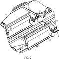
- Each door 20 is operated by hydraulically powered linear actuator 22 connected to a rotatable linkage mechanism 24 extending from one end of the door 20 ( FIG. 2 ).
- the linkage mechanism 24 translates the linear movement of the actuator 22 to rotational movement of the door 20, moving the door 20 between its open and closed positions as the actuator 22 is extended and retracted.
- Each hopper car 12 includes logic and control circuitry 26 operable to command and control the operation of the actuator 22 to open and close the hopper door 20, and to monitor a door position signal from the actuator 22, and from other system sensors and parameters, as will be described in more detail below.
- the logic and control circuitry 26 may be standalone circuitry configured to control and operate just the hopper door system, or the circuitry may be a part of a car control unit or CCU that controls and/or monitors the operation of multiple systems on the car.
- the logic and control circuitry includes one or more processors operable to execute a series of programmed instructions and one or more memory devices operable to store programmed instructions for execution by the circuitry, and one or more memory devices operable to store system data parameters obtained by the logic and control circuitry monitoring the various sensors in the system.
- Each hopper car 12 and control car 14 may include solar panels 30 and batteries 34 to supply power to the logic and control circuitry or CCU, or to other systems located on the car.
- the control car 14 may include one or more generators 38 configured to supply power to the car, with a wiring bus between cars operable to distribute power along the consist.
- Each car may further include a GPS receiver 32 positioning system operable to provide a geographic location of the car.
- the control car 14 is configured similarly to the hopper car 12, and may function as a hopper car for ballast distribution, except that the control car includes a master controller 40 in communication with a plurality of hopper cars 12 via their respective CCUs.
- the logic and control circuitry 26 on the hopper car 12 is in communication with the master controller 40 which provides commands to the logic and control circuitry 26 to operate the hoper doors so that ballast is distributed along the track as commanded.
- the master controller 40 preferably includes a computing device having information compiled from a spreading survey or other information relating to a desired disbursement of ballast and the current location of the hopper car so that ballast can be distributed from the hopper car in the desired manner. Most preferably the master controller 40 is in communication with one or more navigation systems 34 located on at least one of the cars, the consist may further include other communications components 36 configured to transmit and receive data over satellite, cellular, radio, telephone, or other long and/or short range communications networks.
- Communication between the master controller 40 and the logic control circuitry 26 may be through a communications bus or wireline, or may be via other wired or wireless means.
- any of the hopper door actuators may be commanded to direct the associated hopper door to an open or closed position to achieve the desired disbursement of ballast.
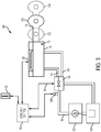
- FIG. 3 a schematic diagram of a hydraulic hopper door control system in accordance with an exemplary embodiment of the present invention is referenced generally by the numeral 100.
- the hopper door control system includes a hydraulic pump 102 in fluid communication with a hydraulic fluid reservoir 104 so that the pump is operable to provide pressurized hydraulic fluid to the system.
- the pressure outlet 106 of the pump 102 is in fluid communication with an electro hydraulic servo valve 108 operable to direct pressurized hydraulic fluid to a linear actuator 110 through valve ports 112, 114 supplying pressurized hydraulic fluid to the actuator body or housing 115 to extend and retract actuator piston or ram 116 relative to the actuator body 115.
- Logic and control circuitry 118 is in electrical communication with the servo valve 108, with a signal from the logic and control circuitry 118 commanding the valve to a desired position to achieve a desired movement of the actuator 110 and in particular movement of ram 116 relative to actuator body 115.
- the actuator 110 can be commanded to a mid-position 120, a retracted position 122, and an extended position 124, with the servo valve 108 directing pressurized hydraulic fluid to the appropriate ports 112, 114 to achieve the desired positioning of the actuator 110.
- a door position sensor 126 positioned internally or externally to the actuator 110 is in communication with the logic and control circuitry 118 and is operable to provide an electrical signal to the circuitry corresponding to the position of the ram 116 of the actuator 110 relative to the actuator body 115.
- the system 100 further includes: a temperature sensor 132 operable to provide a signal to the logic and control circuitry 118 corresponding to the ambient temperature in which the system is operating and a pressure transducer 138 operable to provide an electrical signal corresponding to the hydraulic system pressure to the logic and control circuitry 118.
- hydraulic actuator 110 and logic and control circuitry 118 correspond to the actuator and logic and control circuitry discussed with respect to the exemplary embodiment of FIGS. 1-2 .
- the arrangement and configuration of the system depicted in the schematic diagram of FIG. 3 is exemplary.
- the system may include additional components and/or sensors than those depicted - the hydraulic system may include an accumulator, or the components may be positioned and arranged other than as depicted in the schematic diagram.
- the positioning and arrangement of the temperature and pressure sensors may vary within the scope of the present invention.
- the pressure sensors may be positioned directly adjacent the ports of the hydraulic actuator.
- the system may include fewer or more sensors than those depicted in the exemplary schematic diagram of FIG. 3 , such as including additional pressure sensors, flow sensors, and temperature sensors.
- sensors employed in the system are contemplated by the present invention.
- the actuator position sensor is depicted as a resistive element, other types of sensors, such as encoders or linear variable differential transformer (LVDT) sensors may likewise be employed, with the position sensor located internally or externally to the actuator.
- the position sensor may be a rotary sensor placed on the hopper door pivot or on the linkage mechanism.
- door position and “actuator position” may be used interchangeably as the door is mechanically coupled to the actuator such that they move in tandem.
- the position of the door is directly related to the position of the ram 116 of the actuator 110 such that the door position sensor may physically be located on or in either the actuator 110 or the door 20.
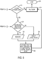
- FIGS. 4 and 5 exemplary operation of the hopper door system will now be described with reference to the flow diagram depicted in FIGS. 4 and 5 , and with reference back to the system depicted in FIGS. 1-3 as described above. It should be understood that the logic and steps of operation depicted and described in FIGS. 4 and 5 are preferably implemented in the logic and control circuitry of the system described above, and that the logic and control circuitry is in communication with the sensors and components of the system as previously described.
- step 200 the process starts at step 200, either when the logic and control circuitry is turned on or initiated, or when the master controller 40 commands the logic and control circuitry 26 to perform an operation, i.e., issues a command to move the hopper car door 20 to a desired position.
- the logic and control circuitry 26 determines whether the hopper door position sensor 126 is operational. Operability of the sensor 126 can be determined by various measurements and logical comparisons performed by the logic and control circuitry 26 with respect to the electrical signals supplied to, and received from, the sensor 126. In the case of a resistive or inductive type position sensor, the circuitry 26 can detect an open circuit or short circuit, can detect whether the supply voltage to the sensor is within a desired range, or can detect if the position signal voltage is outside of an allowable tolerance. In the case of an encoder type position sensor, the circuitry can detect operable communication with the sensor and can detect any fault codes sent by the sensor. Regardless of the type of sensor 126, if the logic and control circuitry 26 determines that the door position sensor 126 is operating properly, the process proceeds to step 204.
- the logic and control circuitry commands the hopper door 20 (via a command to the servo valve 108 and corresponding movement of the actuator 110) to a desired position for distributing ballast from the hopper - by moving the hopper door 20 inwardly or outwardly to an open position - or for containing ballast - by moving the hopper door 20 to its center, closed position.
- the logic and control circuitry monitors the door position sensor 126 to ascertain that the door begins to move after being commanded to do so. If so, at step 208 the logic and control circuitry 26 monitors and records system parameter data from the sensors located throughout the system, preferably including the door position sensor 126, the system hydraulic pressure transducer 138, the ambient temperature sensor 132, and combinations thereof. All of the system parameter data from the various sensors is initially captured and recorded into memory located in the logic and control circuitry 26, or in communication with the logic and control circuitry. A time signal is recorded simultaneously with the sensor data so that each recorded data point for each system parameter can be temporally correlated with the other recorded data points so that a timeline of the reaction of the system parameters during the course of the commanded operation can be constructed.
- the logged data is saved into a data record that indicates the commanded operation and the time and date of the operation.
- the recorded data record is preferably stored to a non-volatile memory within the logic and control circuitry 26. Most preferably, the recorded data is also transferred from the logic and control circuitry to an external storage device or computer system for permanent storage and for further analysis and processing.
- step 202 With the desired movement of the hopper door commanded and completed, the process returns to step 202 to monitor the operability of the door position sensor 126.
- step 212 of FIG. 5 the logic and control circuitry 26 determines whether the hopper door 20 is currently in an open state or a closed state. Determination of the position of the door 20 can be based on the current data from the door position sensor 26, the last known state of the door 20, by determining whether vertical pressure is on the door based on the load condition of the car preprogrammed or sensed by the logic and control circuitry, or by combinations of those data points. If it is determined that the door 20 is currently in a closed position, no ballast is being discharged from the hopper 16, so the door 20 can be left at that position.
- step 212 with the door position sensor 126 failed and the door 20 not currently open, the process proceeds to step 214 where the logic and control circuitry 26 notes a fault in the door system (i.e., the failed door position sensor 126), and sets a flag in the logic and control circuitry 26 that the ballast hopper car position sensor 126 has a fault.
- step 216 further operation of that hopper door 20 is stopped until the system can be repaired.
- the fault flag identifies the particular ballast hopper door 20 that was determined to be inoperable.
- the logic and control circuitry 26 further communicates the detected fault to a master controller 40.
- step 212 with the logic and control circuitry 26 having detected that the door position sensor 126 is not operational and that the hopper door 20 is currently open, ballast is potentially being erroneously discharged from the hopper car 12. Thus, the logic and control circuitry 26 will attempt to operate and close the door 20 in the absence of an operable door position sensor 126.
- step 218 the logic and control circuitry 26 determines whether there exists any previously recorded data corresponding to the desired operation - i.e., moving the hopper door 20 from an open position to a closed position - as would have been recorded as described with respect to steps 204 through 210 of the process.
- step 220 that previously recorded data is moved or read into memory of the logic and control circuitry.
- step 222 the logic and control circuitry 26 determines from the previously recorded data the time it previously took to move the hopper door 20 from the open to the closed position, and issues a command to the servo valve 108 for that same amount of time, commanding the hopper door 20 to the closed position. While that command is executing, i.e., as the hopper door 20 is moving to the closed position, the logic and control circuitry 26 compares the real-time system parameter data - e.g., the hydraulic pressure - to the data recorded from the previous correct operation of closing the hopper door 20.
- the logic and control circuitry 26 determines that the hopper door 20 closed properly.
- the data recorded during normal operation of the hopper door may indicate a pressure drop at the initial movement of the hopper door, and a gradual pressure increase when the hopper door reaches the closed position - all occurring over a specific time interval. If the real-time data correlates closely to that recorded data, e.g., the initial pressure drop and final pressure spike, all over the same time period, are within an allowable tolerance, then the logic and control circuitry determines that the hopper door has closed correctly.
- the logic and control circuitry differentiates between the operation of hopper door when the ballast car is loaded with material, and when the ballast car is not loaded, or empty.
- the ballast car when the ballast car is loaded with ballast material, that material exerts a force, or vertical pressure, against a closed hopper door.
- the pressure of the material against the door causes the door to move less slowly than when there is no material in the car and thus no vertical pressure exerted on the hopper door.
- a door commanded to a closed position moving against the pressure of a ballast load will move more slowly than a door moving against no load.
- the logic and control circuitry is preprogrammed with information as to the load status of the car, and the expected timing of movement of the door is accounted for by the logic and control circuitry.
- the logic and control circuitry receives real-time or updated information regarding the load status of the hopper car and adjusts the door timing parameters accordingly.
- step 214 the fault with the position sensor 126 is flagged.
- step 224 predetermined default values for the system parameter data are used to compare to real-time system parameter data to determine whether the subsequent hopper door 20 closing operation is successful.
- the predetermined default values are derived from data recorded from hopper door test systems or from other hopper door systems in operation. Alternatively, the default values can be calculated or estimated.
- system and method of the present invention allow full operation of a ballast car hopper door 20 - i.e., moving the door to any desired open or closed position - in the event of failure of the door position sensor 126.
- system and method allow full operation of a ballast car hopper door in a system that does not include a door position sensor.
- profiles of recorded system parameter data under various operating conditions -such as varying temperatures, ballast loads, etc. - are obtained for various operations of the hopper door and stored in memory accessible by the logic and control circuitry. For example, moving the hopper door from the closed position to the open inboard position and vice versa, moving the hopper door from the closed position to the open outboard position and vice versa, moving the hopper door from the open inboard to the open outboard position, and any other variations of operation desired.
- the real-time system parameter data e.g., pressure and temperature- is compared to the system parameter data recorded in the corresponding profile.
- the logic and control circuitry determines that the commanded door operation was successful.
- the hopper door can be controlled using recorded system parameter data.
- the recorded data is offloaded to an external computer system and analyzed and/or averaged to obtain default values for use by the logic and control circuitry in the event no operation of the door system has yet been recorded.
- the system includes further sensors, such as additional pressure, flow, and temperature sensors which provide additional data to the logic and control circuitry that is used in the recorded system parameter data profile in a manner similar to that just described.
- the system and method of the present invention can be employed to ensure that a hopper door can be closed in the event of a fault with a door or actuator position sensor to ensure that ballast is not erroneously discharged during that failure, and can be used to control the operation of a hopper door in a system without a door position sensor.
- the system and method of the present invention have been described herein with respect to a hopper door system comprising a linear hydraulic actuator, it should be understood that the system and method of the present invention may similarly be employed in conjunction with other system configurations and power sources.
- the hopper door actuator may be electrically or pneumatically operated, or the actuator may be a rotary actuator configured to directly rotate the hopper door into a desired position.
- voltage and current parameters may be monitored and recorded rather than pressure parameters, however the operation of the system and method remains essentially unchanged.
Landscapes
- Engineering & Computer Science (AREA)
- Mechanical Engineering (AREA)
- Architecture (AREA)
- Structural Engineering (AREA)
- Civil Engineering (AREA)
- Chemical & Material Sciences (AREA)
- Fluid Mechanics (AREA)
- General Engineering & Computer Science (AREA)
- Physics & Mathematics (AREA)
- Analytical Chemistry (AREA)
- Transportation (AREA)
- Power-Operated Mechanisms For Wings (AREA)
- Lighting Device Outwards From Vehicle And Optical Signal (AREA)
- Machines For Laying And Maintaining Railways (AREA)
Description
- Conventional railroads in the United States and elsewhere are typically formed by a compacted sub-grade, a bed of gravel ballast, wooden or concrete cross-ties positioned upon and within the ballast, and parallel steel rails secured to the ties. Variations of construction occur at road and bridge crossings and in other circumstances. The ballast beneath and between the ties stabilizes the positions of the ties, keeps the rails level, and provides some cushioning of the composite structure for loads imposed by rail traffic. However, vibrations from the movement of tracked vehicles over the rails and weathering from wind, rain, ice, and freeze and thaw cycles all contribute to compacting, dislodging, and displacement of some of the ballast over time. Thus, in addition to other maintenance activities, it is necessary to replace ballast periodically to maintain the integrity and safety of railroads.
- Replacement ballast is typically delivered or distributed to the areas along a track in which it is needed using specially designed ballast hopper cars that include a hopper structure holding a quantity of ballast, a ballast chute at the bottom of the hopper in fluid communication with the hopper, and at least one power operated ballast hopper door positioned in the chute. The power operated hopper door typically includes a linear hydraulic actuator controlled via logic control circuitry to selectively open or close the door to control the discharge of ballast. The hopper door is pivotably attached, with an upper end and a distal end of the door moving in opposite directions about the pivot point as the actuator rotates the door between desired positions.
- In typical operation the door is moveable between: a mid, closed position in which the upper end of the door blocks the chute opening so that no ballast can exit the hopper; an open, inboard position in which the distal end of the door is positioned inboard such that ballast is directed from the chute towards the inside of the car, between the rails; and an open, outboard position in which the distal end of the door is positioned outboard such that ballast is directed from the chute towards the outside of the car.
- Typical ballast hopper cars include a front hopper and a rear hopper, with each hopper having two transversely spaced doors, one to the left side of the car and one to the right. Thus, each ballast hopper car typically includes four separate hopper doors to control the discharge of ballast. Each hopper door is independently controlled to discharge ballast outside the rails on the left and/or the right sides of the hopper car, or between the rails, as desired and as controlled by the logic and control circuitry.
- Ballast hopper cars as described above are known from the prior art, e.g.
WO 2016/073749 A1 orUS 8781655 B2 . - Because railroad companies typically maintain hundreds or thousands of miles of track on a recurring schedule, the ballast replacement component of track maintenance is typically a major undertaking in terms of equipment, materials, traffic control, labor, and management. Thus, reliable operation of the ballast hopper doors is essential to the efficient and effective operation of the ballast distribution process.
- In brief, this disclosure describes systems and methods for operating a ballast car hopper door in the event of failure or absence of a hopper door position sensor.
- The present invention provides a system for operating a ballast car hopper door, comprising: an actuator mechanically coupled to a hopper door, the actuator operable to move the hopper door between open and closed positions; a position sensor coupled to the hopper door and operable to generate an electrical signal corresponding to a position of the hopper door; at least one system sensor operable to measure at least one system parameter corresponding to movement of the hopper door, wherein the system parameter is not a position of the hopper door; and logic and control circuitry in communication with the position sensor and the system sensor, wherein the logic and control circuitry is designed: to determine whether the position sensor is functioning properly using data obtained from the position sensor; to command the actuator to move the hopper door to a desired position; and if the position sensor is not functioning properly, to monitor real-time data from the at least one system sensor as the hopper door moves and to compare the real-time data to corresponding stored data to determine that the hopper door moved as commanded.
- The present invention also provides a method for operating a ballast car hopper door, the method comprising: commanding an actuator mechanically coupled to a hopper door to move the door to a desired position; determining whether the position sensor is functioning properly using data obtained from the position sensor; measuring, using at least one system sensor operable to measure at least one system parameter corresponding to movement of the hopper door, wherein the system parameter is not a position of the hopper door, data of at least one system parameter corresponding to movement of the hopper door; comparing the measured data of at least one system parameter as the hopper door moves to stored data and determining that the hopper door moved as commanded.
- In one embodiment, the hopper door system includes a hydraulic linear actuator operable between extended and retracted positions, with hydraulic pressure supplied by a hydraulic pump system. The actuator is coupled to the hopper door by a linkage mechanism such that movement of the actuator main ram is translated to movement of the hopper door. Logic and control circuitry provides command signals to an electro hydraulic servo valve which in turn directs hydraulic pressure to the actuator to achieve a desired hopper door position. A position sensor mounted in or on the actuator, hopper door, or linkage mechanism provides an electrical signal to the logic and control circuitry corresponding to a position of the hopper door.
- In addition to the actuator position sensor, the system includes at least one pressure sensor operable to measure hydraulic system pressure. The sensors are in communication with the logic and control circuitry and provide an electrical signal corresponding to the respective parameter. In alternative embodiments, the system includes a temperature sensor operable to measure the ambient temperature in which the system is operating, additional pressure and flow sensors to measure hydraulic system parameters at additional locations in the hopper door hydraulic systems, and limit switches operable to detect positions of mechanical components.
- In one aspect, the hopper door system is operable to detect a failure of the door position sensor. A position sensor failure can be detected by logic and control circuitry sensing an open or short circuit in the position sensor circuitry, sensing a failure of supply voltage to the sensor, sensing an out of range signal or reading from monitored position sensor data, or sensing that the position sensor signal or data does not change when the actuator has been commanded to move.
- In another aspect, during normal operation of the hopper door system the logic and control circuitry monitors data from the various sensors, including the door position sensor and the hydraulic pressure sensor, and logs or records that system parameter data into memory. In conjunction with the system parameter data, the logic and control circuitry records a time signal to allow the recorded data points to be temporally correlated so that a timeline of system parameter data over the course of a particular command and operation is established. For example, upon commanding the hopper door to open inwardly from a closed position, the logic and control circuitry monitors and records a time signal along with system parameter data from the door position sensor, the hydraulic pressure sensor, and other system sensors.
- The recorded data is stored locally for further access by the logic and control circuitry, and can be offloaded to an external storage device and/or to a computer or database for further review and analysis.
- In yet another aspect, in the event of a detected failure of the door position sensor, or in the absence of a door position sensor, the logic and control circuitry operates and determines the position of the hopper door by comparing real-time system parameters to previously recorded system parameter data and discerning that the real-time data correlates to that recorded data, indicating that the desired hopper door operation was performed. For example, using system parameter data recorded during normal operation of the hopper door being commanded to its open inwardly position, the logic and control circuitry commands the door to the open inwardly position and compares the real-time system parameter data - e.g., time and pressure - to the previously recorded data for that operation. If the real-time system parameter data correlates within a predetermined tolerance to the recorded system parameter data, the logic and control circuitry ascertains that the desired command was performed correctly, and the door moved to the open inwardly position. In alternative embodiments, the logic and control circuitry uses predetermined default values in place of recorded system parameter data.
- Thus, operation of the hopper door and determination of the door's position can be attained in the event of failure of the actuator position sensor. In such a scenario, operation of the hopper door is effected via the logic and control circuitry using system parameter data from other system sensors.
- Illustrative embodiments of the invention are described in detail below with reference to the attached drawing figures, and wherein:
-
FIG. 1 is a side elevational view of a hopper car and a control car for distributing ballast depicted in accordance with an exemplary embodiment of the present invention; -
FIG. 2 is an enlarged fragmentary perspective view of two ballast discharge chutes associated with a hopper of the hopper car and each including a ballast door and actuator depicted in accordance with an exemplary embodiment of the present invention; -
FIG. 3 is diagrammatic schematic view of a system for operating a ballast car hopper door in accordance with an exemplary embodiment of the present invention; -
FIGS. 4 and5 are flow diagrams depicting a method for controlling a ballast car hopper door in accordance with an exemplary embodiment of the present invention. -
FIG. 1 shows a portion of a ballast delivery consist 10 including ahopper car 12 and acontrol car 14. Thehopper car 12 andcontrol 14 are typically a part of a larger consist comprising a plurality of hopper cars and control cars, with at least one power or propulsion unit for propelling the consist along arailway 13. In one embodiment, the consist includes onecontrol car 14 for approximately each thirtyhopper cars 12, although other ratios may be employed. - Each
hopper car 12 includes two longitudinallyadjacent hoppers 16, with left andright ballast chutes 18 formed at the lower portion of eachhopper 16. The sloped configuration of thehoppers 16 and chutes 18 directs ballast in the chute downwardly towards the bottom of the car for disbursement along a rail track. - An elongated, pivotably mounted
ballast door 20 is positioned at the bottom of eachchute 18 and is operable to control the flow of ballast from the respective chute. When thedoor 20 is positioned at its midpoint, the upper portion of the door is positioned to cover the bottom opening of theballast chute 14 to prevent ballast from exiting thehopper 16. When the upper end of thedoor 20 is rotated inwardly, towards the inside of the car with the lower end of thedoor 20 angled outward relative to the car, the bottom opening of theballast chute 18 is uncovered so that ballast falls from the chute and onto the outwardly slopingballast door 20 which directs the downwardly flowing ballast toward the outside of the car. And, when the upper end of thedoor 20 is rotated outwardly, towards the outside of the car with the lower end of thedoor 20 angled inward relative to the car, the bottom opening of theballast chute 18 is uncovered so that ballast falls from the chute and onto the inwardly slopingballast door 20 which directs the downwardly flowing ballast toward the inside of the car, between the rails. - Each
door 20 is operated by hydraulically poweredlinear actuator 22 connected to arotatable linkage mechanism 24 extending from one end of the door 20 (FIG. 2 ). Thelinkage mechanism 24 translates the linear movement of theactuator 22 to rotational movement of thedoor 20, moving thedoor 20 between its open and closed positions as theactuator 22 is extended and retracted. - Each
hopper car 12 includes logic andcontrol circuitry 26 operable to command and control the operation of theactuator 22 to open and close thehopper door 20, and to monitor a door position signal from theactuator 22, and from other system sensors and parameters, as will be described in more detail below. The logic andcontrol circuitry 26 may be standalone circuitry configured to control and operate just the hopper door system, or the circuitry may be a part of a car control unit or CCU that controls and/or monitors the operation of multiple systems on the car. - Most preferably, the logic and control circuitry includes one or more processors operable to execute a series of programmed instructions and one or more memory devices operable to store programmed instructions for execution by the circuitry, and one or more memory devices operable to store system data parameters obtained by the logic and control circuitry monitoring the various sensors in the system.
- Each
hopper car 12 andcontrol car 14 may includesolar panels 30 andbatteries 34 to supply power to the logic and control circuitry or CCU, or to other systems located on the car. Thecontrol car 14 may include one or more generators 38 configured to supply power to the car, with a wiring bus between cars operable to distribute power along the consist. Each car may further include aGPS receiver 32 positioning system operable to provide a geographic location of the car. - As depicted in
FIG. 1 , thecontrol car 14 is configured similarly to thehopper car 12, and may function as a hopper car for ballast distribution, except that the control car includes amaster controller 40 in communication with a plurality ofhopper cars 12 via their respective CCUs. In one exemplary embodiment, the logic andcontrol circuitry 26 on thehopper car 12 is in communication with themaster controller 40 which provides commands to the logic andcontrol circuitry 26 to operate the hoper doors so that ballast is distributed along the track as commanded. - The
master controller 40 preferably includes a computing device having information compiled from a spreading survey or other information relating to a desired disbursement of ballast and the current location of the hopper car so that ballast can be distributed from the hopper car in the desired manner. Most preferably themaster controller 40 is in communication with one ormore navigation systems 34 located on at least one of the cars, the consist may further includeother communications components 36 configured to transmit and receive data over satellite, cellular, radio, telephone, or other long and/or short range communications networks. - Communication between the
master controller 40 and thelogic control circuitry 26 may be through a communications bus or wireline, or may be via other wired or wireless means. Thus, upon command from the logic and control circuitry, any of the hopper door actuators may be commanded to direct the associated hopper door to an open or closed position to achieve the desired disbursement of ballast. - Turning to
FIG. 3 , a schematic diagram of a hydraulic hopper door control system in accordance with an exemplary embodiment of the present invention is referenced generally by the numeral 100. The hopper door control system includes ahydraulic pump 102 in fluid communication with ahydraulic fluid reservoir 104 so that the pump is operable to provide pressurized hydraulic fluid to the system. Thepressure outlet 106 of thepump 102 is in fluid communication with an electrohydraulic servo valve 108 operable to direct pressurized hydraulic fluid to alinear actuator 110 throughvalve ports housing 115 to extend and retract actuator piston or ram 116 relative to theactuator body 115. Logic andcontrol circuitry 118 is in electrical communication with theservo valve 108, with a signal from the logic andcontrol circuitry 118 commanding the valve to a desired position to achieve a desired movement of theactuator 110 and in particular movement ofram 116 relative toactuator body 115. As depicted inFIG. 3 , theactuator 110 can be commanded to amid-position 120, a retractedposition 122, and anextended position 124, with theservo valve 108 directing pressurized hydraulic fluid to theappropriate ports actuator 110. Adoor position sensor 126 positioned internally or externally to theactuator 110 is in communication with the logic andcontrol circuitry 118 and is operable to provide an electrical signal to the circuitry corresponding to the position of theram 116 of theactuator 110 relative to theactuator body 115. - The
system 100 further includes: atemperature sensor 132 operable to provide a signal to the logic andcontrol circuitry 118 corresponding to the ambient temperature in which the system is operating and apressure transducer 138 operable to provide an electrical signal corresponding to the hydraulic system pressure to the logic andcontrol circuitry 118. - It should be understood that the
hydraulic actuator 110 and logic andcontrol circuitry 118 correspond to the actuator and logic and control circuitry discussed with respect to the exemplary embodiment ofFIGS. 1-2 . - It should be further understood that the arrangement and configuration of the system depicted in the schematic diagram of
FIG. 3 is exemplary. For example, the system may include additional components and/or sensors than those depicted - the hydraulic system may include an accumulator, or the components may be positioned and arranged other than as depicted in the schematic diagram. Similarly, the positioning and arrangement of the temperature and pressure sensors may vary within the scope of the present invention. For example, the pressure sensors may be positioned directly adjacent the ports of the hydraulic actuator. - Additionally, the system may include fewer or more sensors than those depicted in the exemplary schematic diagram of
FIG. 3 , such as including additional pressure sensors, flow sensors, and temperature sensors. Furthermore, variations in the types of sensors employed in the system are contemplated by the present invention. For example, while the actuator position sensor is depicted as a resistive element, other types of sensors, such as encoders or linear variable differential transformer (LVDT) sensors may likewise be employed, with the position sensor located internally or externally to the actuator. In alternative embodiments, the position sensor may be a rotary sensor placed on the hopper door pivot or on the linkage mechanism. It should be understood that as used herein, "door position" and "actuator position" may be used interchangeably as the door is mechanically coupled to the actuator such that they move in tandem. Thus, the position of the door is directly related to the position of theram 116 of theactuator 110 such that the door position sensor may physically be located on or in either theactuator 110 or thedoor 20. - With the components and sensors of the hopper door control system set forth, exemplary operation of the hopper door system will now be described with reference to the flow diagram depicted in
FIGS. 4 and5 , and with reference back to the system depicted inFIGS. 1-3 as described above. It should be understood that the logic and steps of operation depicted and described inFIGS. 4 and5 are preferably implemented in the logic and control circuitry of the system described above, and that the logic and control circuitry is in communication with the sensors and components of the system as previously described. - Looking to
FIG. 4 , the process starts atstep 200, either when the logic and control circuitry is turned on or initiated, or when themaster controller 40 commands the logic andcontrol circuitry 26 to perform an operation, i.e., issues a command to move thehopper car door 20 to a desired position. - At
step 202, the logic andcontrol circuitry 26 determines whether the hopperdoor position sensor 126 is operational. Operability of thesensor 126 can be determined by various measurements and logical comparisons performed by the logic andcontrol circuitry 26 with respect to the electrical signals supplied to, and received from, thesensor 126. In the case of a resistive or inductive type position sensor, thecircuitry 26 can detect an open circuit or short circuit, can detect whether the supply voltage to the sensor is within a desired range, or can detect if the position signal voltage is outside of an allowable tolerance. In the case of an encoder type position sensor, the circuitry can detect operable communication with the sensor and can detect any fault codes sent by the sensor. Regardless of the type ofsensor 126, if the logic andcontrol circuitry 26 determines that thedoor position sensor 126 is operating properly, the process proceeds to step 204. - At
step 204, the logic and control circuitry commands the hopper door 20 (via a command to theservo valve 108 and corresponding movement of the actuator 110) to a desired position for distributing ballast from the hopper - by moving thehopper door 20 inwardly or outwardly to an open position - or for containing ballast - by moving thehopper door 20 to its center, closed position. - Proceeding to step 206, with the command to move the
door 20 issued, the logic and control circuitry monitors thedoor position sensor 126 to ascertain that the door begins to move after being commanded to do so. If so, atstep 208 the logic andcontrol circuitry 26 monitors and records system parameter data from the sensors located throughout the system, preferably including thedoor position sensor 126, the systemhydraulic pressure transducer 138, theambient temperature sensor 132, and combinations thereof. All of the system parameter data from the various sensors is initially captured and recorded into memory located in the logic andcontrol circuitry 26, or in communication with the logic and control circuitry. A time signal is recorded simultaneously with the sensor data so that each recorded data point for each system parameter can be temporally correlated with the other recorded data points so that a timeline of the reaction of the system parameters during the course of the commanded operation can be constructed. - Upon completion of the commanded movement, at
step 210 the logged data is saved into a data record that indicates the commanded operation and the time and date of the operation. The recorded data record is preferably stored to a non-volatile memory within the logic andcontrol circuitry 26. Most preferably, the recorded data is also transferred from the logic and control circuitry to an external storage device or computer system for permanent storage and for further analysis and processing. - With the desired movement of the hopper door commanded and completed, the process returns to step 202 to monitor the operability of the
door position sensor 126. - Looking again to block 202, if the logic and
control circuitry 26 determines that thedoor position sensor 126 is not operational, the process proceeds to step 212 ofFIG. 5 , where the logic andcontrol circuitry 26 determines whether thehopper door 20 is currently in an open state or a closed state. Determination of the position of thedoor 20 can be based on the current data from thedoor position sensor 26, the last known state of thedoor 20, by determining whether vertical pressure is on the door based on the load condition of the car preprogrammed or sensed by the logic and control circuitry, or by combinations of those data points. If it is determined that thedoor 20 is currently in a closed position, no ballast is being discharged from thehopper 16, so thedoor 20 can be left at that position. - At
step 212, with thedoor position sensor 126 failed and thedoor 20 not currently open, the process proceeds to step 214 where the logic andcontrol circuitry 26 notes a fault in the door system (i.e., the failed door position sensor 126), and sets a flag in the logic andcontrol circuitry 26 that the ballast hoppercar position sensor 126 has a fault. Atstep 216 further operation of thathopper door 20 is stopped until the system can be repaired. Preferably, the fault flag identifies the particularballast hopper door 20 that was determined to be inoperable. Most preferably, the logic andcontrol circuitry 26 further communicates the detected fault to amaster controller 40. - Returning to step 212, with the logic and
control circuitry 26 having detected that thedoor position sensor 126 is not operational and that thehopper door 20 is currently open, ballast is potentially being erroneously discharged from thehopper car 12. Thus, the logic andcontrol circuitry 26 will attempt to operate and close thedoor 20 in the absence of an operabledoor position sensor 126. - At
step 218 the logic andcontrol circuitry 26 determines whether there exists any previously recorded data corresponding to the desired operation - i.e., moving thehopper door 20 from an open position to a closed position - as would have been recorded as described with respect tosteps 204 through 210 of the process. - If the logic and
control circuitry 26 determines that there is previously recorded data for the desired operation, atstep 220 that previously recorded data is moved or read into memory of the logic and control circuitry. Atstep 222, the logic andcontrol circuitry 26 determines from the previously recorded data the time it previously took to move thehopper door 20 from the open to the closed position, and issues a command to theservo valve 108 for that same amount of time, commanding thehopper door 20 to the closed position. While that command is executing, i.e., as thehopper door 20 is moving to the closed position, the logic andcontrol circuitry 26 compares the real-time system parameter data - e.g., the hydraulic pressure - to the data recorded from the previous correct operation of closing thehopper door 20. - If the real-time system parameter data correlates to the corresponding recorded system parameter data within an allowable tolerance, the logic and
control circuitry 26 determines that thehopper door 20 closed properly. For example, the data recorded during normal operation of the hopper door may indicate a pressure drop at the initial movement of the hopper door, and a gradual pressure increase when the hopper door reaches the closed position - all occurring over a specific time interval. If the real-time data correlates closely to that recorded data, e.g., the initial pressure drop and final pressure spike, all over the same time period, are within an allowable tolerance, then the logic and control circuitry determines that the hopper door has closed correctly. - In one exemplary embodiment, the logic and control circuitry differentiates between the operation of hopper door when the ballast car is loaded with material, and when the ballast car is not loaded, or empty. For example, when the ballast car is loaded with ballast material, that material exerts a force, or vertical pressure, against a closed hopper door. When the door is commanded open from that closed position the pressure of the material against the door causes the door to move less slowly than when there is no material in the car and thus no vertical pressure exerted on the hopper door. Similarly, a door commanded to a closed position moving against the pressure of a ballast load will move more slowly than a door moving against no load. Thus, preferably, the logic and control circuitry is preprogrammed with information as to the load status of the car, and the expected timing of movement of the door is accounted for by the logic and control circuitry. In alternative embodiments, the logic and control circuitry receives real-time or updated information regarding the load status of the hopper car and adjusts the door timing parameters accordingly.
- With the
door 20 thus moved to the closed position, the process proceeds to step 214, where the fault with theposition sensor 126 is flagged. - Returning to step 218, if the logic and
control circuitry 26 has not previously recorded system parameter data for a corresponding normal door operation, the process proceeds to step 224 where predetermined default values for the system parameter data are used to compare to real-time system parameter data to determine whether thesubsequent hopper door 20 closing operation is successful. Preferably, the predetermined default values are derived from data recorded from hopper door test systems or from other hopper door systems in operation. Alternatively, the default values can be calculated or estimated. - In alternative embodiments, the system and method of the present invention allow full operation of a ballast car hopper door 20 - i.e., moving the door to any desired open or closed position - in the event of failure of the
door position sensor 126. - In further embodiments, the system and method allow full operation of a ballast car hopper door in a system that does not include a door position sensor.
- In those alternative embodiments, profiles of recorded system parameter data under various operating conditions -such as varying temperatures, ballast loads, etc. - are obtained for various operations of the hopper door and stored in memory accessible by the logic and control circuitry. For example, moving the hopper door from the closed position to the open inboard position and vice versa, moving the hopper door from the closed position to the open outboard position and vice versa, moving the hopper door from the open inboard to the open outboard position, and any other variations of operation desired. During operation of the door the real-time system parameter data -e.g., pressure and temperature- is compared to the system parameter data recorded in the corresponding profile. If the real-time system parameter data compares within an allowable tolerance to the recorded system parameter data, the logic and control circuitry determines that the commanded door operation was successful. Thus, in a system that does not include a door position sensor, the hopper door can be controlled using recorded system parameter data.
- In further alternative embodiments, the recorded data is offloaded to an external computer system and analyzed and/or averaged to obtain default values for use by the logic and control circuitry in the event no operation of the door system has yet been recorded. In other embodiments, the system includes further sensors, such as additional pressure, flow, and temperature sensors which provide additional data to the logic and control circuitry that is used in the recorded system parameter data profile in a manner similar to that just described.
- From the above, it can be seen that the system and method of the present invention can be employed to ensure that a hopper door can be closed in the event of a fault with a door or actuator position sensor to ensure that ballast is not erroneously discharged during that failure, and can be used to control the operation of a hopper door in a system without a door position sensor.
- While the system and method of the present invention have been described herein with respect to a hopper door system comprising a linear hydraulic actuator, it should be understood that the system and method of the present invention may similarly be employed in conjunction with other system configurations and power sources. For example, the hopper door actuator may be electrically or pneumatically operated, or the actuator may be a rotary actuator configured to directly rotate the hopper door into a desired position. In an electrically actuated system voltage and current parameters may be monitored and recorded rather than pressure parameters, however the operation of the system and method remains essentially unchanged.
Claims (14)
- A system (100) for operating a ballast car hopper door (20), comprising:an actuator (22, 110) mechanically coupled to a hopper door (20), the actuator (22, 110) operable to move the hopper door (20) between open and closed positions;a door position sensor (126) coupled to the hopper door (20) and operable to generate an electrical signal corresponding to a position of the hopper door (20);at least one further system sensor operable to measure at least one system parameter corresponding to movement of the hopper door (20), wherein the system parameter is not a position of the hopper door (20); andlogic and control circuitry (26, 118) in communication with the position sensor (126) and the system sensor, wherein the logic and control circuitry (26, 118) is designed:to determine whether the position sensor (126) is functioning properly using data obtained from the position sensor (126);to command the actuator (22, 110) to move the hopper door (20) to a desired position; andif the position sensor (126) is not functioning properly, to monitor real-time data from the at least one system sensor as the hopper door (20) moves and to compare the real-time data to corresponding stored data to determine that the hopper door (20) moved as commanded.
- The system of claim 1, wherein the at least one system sensor is selected from the group consisting of: hydraulic pressure sensors, flow sensors, temperature sensors, voltage sensors, current sensors, and combinations thereof.
- The system of any one of claims 1 to 2, wherein the logic and control circuitry (26, 118) is configured to further: record into memory real time data from the at least one system sensor as the hopper door (20) moves.
- The system of claim 3, wherein the logic and control circuitry (26, 118) is configured to further: record into memory a time signal to temporally correlate data recorded from the at least one system sensor.
- The system of any one of claims 1 to 4, wherein the stored data is to be derived from previously-recorded data obtained from the at least one system sensor.
- The system of any one of claims 1 to 4, wherein the stored data is predetermined calculated data.
- A method for operating a ballast car hopper door (20), the method comprising:commanding an actuator (22, 110) mechanically coupled to a hopper door (20) to move the door to a desired position;providing a door position sensor (126) and determining whether the door position sensor (126) is functioning properly using data obtained from said position sensor;measuring, using at least one system sensor operable to measure at least one system parameter corresponding to movement of the hopper door, wherein the system parameter is not a position of the hopper door, data of at least one system parameter corresponding to movement of the hopper door (20);comparing the measured data of at least one system parameter as the hopper door (20) moves to stored data and determining that the hopper door (20) moved as commanded.
- The method of claim 7, wherein the at least one system parameter is selected from the group consisting of: hydraulic pressure, flow, ambient temperature, voltage, current, and combinations thereof.
- The method of claim 7 or 8, further comprising:
recording into memory the real-time data representing the measured at least one system parameter. - The method of claim 9, further comprising:
recording into memory a time signal temporally correlating the real-time data representing the measured at least one system parameter. - The method of any one of claims 7 to 10, further comprising:
measuring a position of the hopper door (20) and comparing the measured position to the measured data of at least one system parameter and calculating a difference between the two. - The method of claim 11, further comprising:
comparing the measured position of the hopper door (20) to the stored data and calculating a difference between the two. - The method of any one of claims 7 to 12, wherein the stored data is derived from previously-recorded data corresponding to a system parameter or from previously-recorded data obtained from measurement of at least one system parameter.
- The method of any one of claims 7 to 12, wherein the stored data is predetermined calculated data.
Applications Claiming Priority (2)
| Application Number | Priority Date | Filing Date | Title |
|---|---|---|---|
| US201662420695P | 2016-11-11 | 2016-11-11 | |
| US15/790,664 US10787109B2 (en) | 2016-11-11 | 2017-10-23 | System and method for operating a ballast car hopper door |
Publications (2)
| Publication Number | Publication Date |
|---|---|
| EP3321420A1 EP3321420A1 (en) | 2018-05-16 |
| EP3321420B1 true EP3321420B1 (en) | 2019-10-23 |
Family
ID=60301895
Family Applications (1)
| Application Number | Title | Priority Date | Filing Date |
|---|---|---|---|
| EP17201056.3A Not-in-force EP3321420B1 (en) | 2016-11-11 | 2017-11-10 | System and method for operating a ballast car hopper door |
Country Status (5)
| Country | Link |
|---|---|
| US (1) | US10787109B2 (en) |
| EP (1) | EP3321420B1 (en) |
| AU (1) | AU2017254923A1 (en) |
| CA (1) | CA2984074C (en) |
| MX (1) | MX383909B (en) |
Families Citing this family (1)
| Publication number | Priority date | Publication date | Assignee | Title |
|---|---|---|---|---|
| US10787109B2 (en) * | 2016-11-11 | 2020-09-29 | Herzog Railroad Services, Inc. | System and method for operating a ballast car hopper door |
Family Cites Families (31)
| Publication number | Priority date | Publication date | Assignee | Title |
|---|---|---|---|---|
| US3596565A (en) | 1969-07-25 | 1971-08-03 | Duane Edward Atkinson | Remotely controlled hydraulic system |
| US4326750A (en) | 1979-12-17 | 1982-04-27 | Cmi Corporation | Gate assembly and control assembly therefor |
| DE3014432A1 (en) | 1980-04-15 | 1981-10-22 | Zimmermann & Jansen GmbH, 5160 Düren | DEVICE FOR ACCURATE POSITION REPORTING OF A DOUBLE-SIDED APPLICABLE PISTON IN A HYDRAULIC WORKING CYLINDER |
| US4542701A (en) | 1983-03-14 | 1985-09-24 | Miner Enterprises, Inc. | Tamper-proof railroad hopper car door operating system |
| DE3520199A1 (en) | 1984-10-05 | 1986-04-10 | Wabco Westinghouse Steuerungstechnik GmbH & Co, 3000 Hannover | POTENTIOMETER |
| AU8941691A (en) | 1990-10-31 | 1992-05-26 | Loram Maintenance Of Way, Inc. | Ballast distribution, regulation and reclaiming railroad maintenance device |
| US5311822A (en) | 1992-12-07 | 1994-05-17 | Herzog Contracting Corporation | Ballast hopper door control apparatus and method with independently and selectively actuated motors in response to uniquely coded signals |
| US5423268A (en) | 1992-12-07 | 1995-06-13 | Herzog Contracting Corporation | Railroad hopper car with ballast distributing blade and hopper door and blade control apparatus and method |
| US5359942A (en) | 1993-08-27 | 1994-11-01 | Difco, Inc. | Remote control positioning system for controlling hopper doors |
| US5586669A (en) | 1995-05-03 | 1996-12-24 | Fm Industries, Inc. | Cushioning unit fault detector |
| US5657700A (en) | 1995-12-14 | 1997-08-19 | Herzog Contracting Corporation | Railroad hopper car with ballast distributing blades and remote control system |
| US6142059A (en) | 1996-11-27 | 2000-11-07 | Case Corporation | Method and apparatus for sensing the orientation of a mechanical actuator |
| CA2218168A1 (en) * | 1997-10-14 | 1999-04-14 | Midland Manufacturing, Ltd. | Control device for trailer gates |
| US6704626B1 (en) * | 1999-04-02 | 2004-03-09 | Herzog Contracting Corp. | Logistics system and method with position control |
| US7552671B2 (en) | 2002-01-04 | 2009-06-30 | Parker-Hannifin Corporation | Cylinder with fiber optical position sensing device and method |
| US7059238B2 (en) | 2003-10-17 | 2006-06-13 | Clark Equipment Company | Method and apparatus for stroke position sensor for hydraulic cylinder |
| US7093544B1 (en) | 2004-01-06 | 2006-08-22 | Lexair, Inc. | Control device for a railroad car |
| US7152347B2 (en) | 2004-06-17 | 2006-12-26 | Herzog Contracting Corporation | Method and apparatus for applying railway ballast |
| US20070079726A1 (en) | 2004-08-10 | 2007-04-12 | Creighton George S | Over Center Lock Indicator For Railway Car Door Operation Mechanism |
| US7367272B2 (en) | 2004-08-31 | 2008-05-06 | Taylor Fred J | Door position indicating mechanism for a railcar |
| WO2007084624A2 (en) * | 2006-01-20 | 2007-07-26 | Miller Douglas C | Automated gate control and methods |
| US8038231B1 (en) | 2007-02-27 | 2011-10-18 | Lexair, Inc. | Control valve |
| CA2992482C (en) | 2009-01-27 | 2020-05-12 | National Steel Car Limited | Railroad car and door mechanism therefor |
| CN102582641A (en) | 2011-01-06 | 2012-07-18 | 齐齐哈尔轨道交通装备有限责任公司 | Control system for unloading door of ballast hopper car |
| US9175998B2 (en) | 2011-03-04 | 2015-11-03 | Georgetown Rail Equipment Company | Ballast delivery and computation system and method |
| US8596203B2 (en) | 2011-05-11 | 2013-12-03 | National Steel Car Limited | Railroad car and door mechanism therefor |
| US9051695B2 (en) | 2011-10-18 | 2015-06-09 | Herzog Railroad Services, Inc. | Automated track surveying and ballast replacement |
| US8781655B2 (en) | 2011-10-18 | 2014-07-15 | Herzog Railroad Services, Inc. | Automated track surveying and ballast replacement |
| AU2015343007B2 (en) | 2014-11-05 | 2017-05-11 | Herzog Railroad Services, Inc. | Material transport and distribution consist with controlled gated hopper cars and conveyor systems |
| US10138603B2 (en) | 2015-10-01 | 2018-11-27 | Herzog Railroad Services, Inc. | Autonomous ballast unloading consist |
| US10787109B2 (en) * | 2016-11-11 | 2020-09-29 | Herzog Railroad Services, Inc. | System and method for operating a ballast car hopper door |
-
2017
- 2017-10-23 US US15/790,664 patent/US10787109B2/en active Active
- 2017-10-27 CA CA2984074A patent/CA2984074C/en active Active
- 2017-11-02 AU AU2017254923A patent/AU2017254923A1/en not_active Abandoned
- 2017-11-09 MX MX2017014384A patent/MX383909B/en unknown
- 2017-11-10 EP EP17201056.3A patent/EP3321420B1/en not_active Not-in-force
Non-Patent Citations (1)
| Title |
|---|
| None * |
Also Published As
| Publication number | Publication date |
|---|---|
| MX2017014384A (en) | 2018-10-02 |
| MX383909B (en) | 2025-03-14 |
| US20180134201A1 (en) | 2018-05-17 |
| EP3321420A1 (en) | 2018-05-16 |
| CA2984074C (en) | 2021-11-30 |
| AU2017254923A1 (en) | 2018-05-31 |
| US10787109B2 (en) | 2020-09-29 |
| CA2984074A1 (en) | 2018-05-11 |
Similar Documents
| Publication | Publication Date | Title |
|---|---|---|
| US6526339B1 (en) | GPS controlled multiple source material application | |
| US7707944B2 (en) | Method and apparatus for applying railway ballast | |
| US20210269077A1 (en) | Smart sensor data transmission in railway infrastructure | |
| CA2942956C (en) | Autonomous ballast delivery consist | |
| US10787109B2 (en) | System and method for operating a ballast car hopper door | |
| US6758147B2 (en) | Ballast discharge system | |
| US12146270B2 (en) | Rail tie plate distribution system | |
| AU2020267261B2 (en) | Trim Chute | |
| RU2608194C2 (en) | Device for heated switch heating elements operating capacity monitoring | |
| WO2007146799A2 (en) | Railroad track de-icing method and apparatus | |
| EP4448367A1 (en) | Track system comprising a spindle assembly having an integrated sensor | |
| AU2012398058A1 (en) | Predictive method for analysing tampering equipment, and tampering equipment | |
| AT524500A1 (en) | Method and system for operating a railway system | |
| US12435474B2 (en) | Auto stow wings | |
| US12434750B2 (en) | Monitoring system for a plurality of homogeneous devices of at least two convoys, in particular two railway convoys | |
| US20230002977A1 (en) | Gapless railway diamond: a new type of railway track component providing unbroken running surfaces across the flangeways of an intersecting railway line | |
| Lara et al. | Grasberg block cave mine rail project update–PT Freeport Indonesia | |
| Biro et al. | Rethinking mining transport: Trackless trains for mass transport in mining | |
| Halliday | Performance by design [railway industry] | |
| BR102022025052A2 (en) | RAIL SLEEP HANDLING SYSTEM | |
| DE102018006587A1 (en) | Trackage sensor | |
| HRP20191648A2 (en) | RAILWAY WAGON FOR TRANSPORT OF INERT MATERIALS | |
| HK40011526A (en) | Method and system for monitoring a point system of a railway network, and point system of a railway network |
Legal Events
| Date | Code | Title | Description |
|---|---|---|---|
| PUAI | Public reference made under article 153(3) epc to a published international application that has entered the european phase |
Free format text: ORIGINAL CODE: 0009012 |
|
| STAA | Information on the status of an ep patent application or granted ep patent |
Free format text: STATUS: THE APPLICATION HAS BEEN PUBLISHED |
|
| AK | Designated contracting states |
Kind code of ref document: A1 Designated state(s): AL AT BE BG CH CY CZ DE DK EE ES FI FR GB GR HR HU IE IS IT LI LT LU LV MC MK MT NL NO PL PT RO RS SE SI SK SM TR |
|
| AX | Request for extension of the european patent |
Extension state: BA ME |
|
| STAA | Information on the status of an ep patent application or granted ep patent |
Free format text: STATUS: REQUEST FOR EXAMINATION WAS MADE |
|
| 17P | Request for examination filed |
Effective date: 20181116 |
|
| RBV | Designated contracting states (corrected) |
Designated state(s): AL AT BE BG CH CY CZ DE DK EE ES FI FR GB GR HR HU IE IS IT LI LT LU LV MC MK MT NL NO PL PT RO RS SE SI SK SM TR |
|
| GRAP | Despatch of communication of intention to grant a patent |
Free format text: ORIGINAL CODE: EPIDOSNIGR1 |
|
| STAA | Information on the status of an ep patent application or granted ep patent |
Free format text: STATUS: GRANT OF PATENT IS INTENDED |
|
| RIC1 | Information provided on ipc code assigned before grant |
Ipc: B61D 15/00 20060101ALI20190626BHEP Ipc: F15B 21/08 20060101ALN20190626BHEP Ipc: E01B 27/02 20060101AFI20190626BHEP Ipc: B60P 1/56 20060101ALN20190626BHEP |
|
| INTG | Intention to grant announced |
Effective date: 20190715 |
|
| GRAS | Grant fee paid |
Free format text: ORIGINAL CODE: EPIDOSNIGR3 |
|
| GRAA | (expected) grant |
Free format text: ORIGINAL CODE: 0009210 |
|
| STAA | Information on the status of an ep patent application or granted ep patent |
Free format text: STATUS: THE PATENT HAS BEEN GRANTED |
|
| AK | Designated contracting states |
Kind code of ref document: B1 Designated state(s): AL AT BE BG CH CY CZ DE DK EE ES FI FR GB GR HR HU IE IS IT LI LT LU LV MC MK MT NL NO PL PT RO RS SE SI SK SM TR |
|
| REG | Reference to a national code |
Ref country code: GB Ref legal event code: FG4D |
|
| REG | Reference to a national code |
Ref country code: CH Ref legal event code: EP |
|
| REG | Reference to a national code |
Ref country code: IE Ref legal event code: FG4D |
|
| REG | Reference to a national code |
Ref country code: DE Ref legal event code: R096 Ref document number: 602017008026 Country of ref document: DE |
|
| REG | Reference to a national code |
Ref country code: AT Ref legal event code: REF Ref document number: 1193739 Country of ref document: AT Kind code of ref document: T Effective date: 20191115 |
|
| REG | Reference to a national code |
Ref country code: NL Ref legal event code: MP Effective date: 20191023 |
|
| REG | Reference to a national code |
Ref country code: LT Ref legal event code: MG4D |
|
| PG25 | Lapsed in a contracting state [announced via postgrant information from national office to epo] |
Ref country code: LV Free format text: LAPSE BECAUSE OF FAILURE TO SUBMIT A TRANSLATION OF THE DESCRIPTION OR TO PAY THE FEE WITHIN THE PRESCRIBED TIME-LIMIT Effective date: 20191023 Ref country code: SE Free format text: LAPSE BECAUSE OF FAILURE TO SUBMIT A TRANSLATION OF THE DESCRIPTION OR TO PAY THE FEE WITHIN THE PRESCRIBED TIME-LIMIT Effective date: 20191023 Ref country code: FI Free format text: LAPSE BECAUSE OF FAILURE TO SUBMIT A TRANSLATION OF THE DESCRIPTION OR TO PAY THE FEE WITHIN THE PRESCRIBED TIME-LIMIT Effective date: 20191023 Ref country code: BG Free format text: LAPSE BECAUSE OF FAILURE TO SUBMIT A TRANSLATION OF THE DESCRIPTION OR TO PAY THE FEE WITHIN THE PRESCRIBED TIME-LIMIT Effective date: 20200123 Ref country code: PT Free format text: LAPSE BECAUSE OF FAILURE TO SUBMIT A TRANSLATION OF THE DESCRIPTION OR TO PAY THE FEE WITHIN THE PRESCRIBED TIME-LIMIT Effective date: 20200224 Ref country code: PL Free format text: LAPSE BECAUSE OF FAILURE TO SUBMIT A TRANSLATION OF THE DESCRIPTION OR TO PAY THE FEE WITHIN THE PRESCRIBED TIME-LIMIT Effective date: 20191023 Ref country code: GR Free format text: LAPSE BECAUSE OF FAILURE TO SUBMIT A TRANSLATION OF THE DESCRIPTION OR TO PAY THE FEE WITHIN THE PRESCRIBED TIME-LIMIT Effective date: 20200124 Ref country code: NO Free format text: LAPSE BECAUSE OF FAILURE TO SUBMIT A TRANSLATION OF THE DESCRIPTION OR TO PAY THE FEE WITHIN THE PRESCRIBED TIME-LIMIT Effective date: 20200123 Ref country code: NL Free format text: LAPSE BECAUSE OF FAILURE TO SUBMIT A TRANSLATION OF THE DESCRIPTION OR TO PAY THE FEE WITHIN THE PRESCRIBED TIME-LIMIT Effective date: 20191023 Ref country code: LT Free format text: LAPSE BECAUSE OF FAILURE TO SUBMIT A TRANSLATION OF THE DESCRIPTION OR TO PAY THE FEE WITHIN THE PRESCRIBED TIME-LIMIT Effective date: 20191023 |
|
| PG25 | Lapsed in a contracting state [announced via postgrant information from national office to epo] |
Ref country code: HR Free format text: LAPSE BECAUSE OF FAILURE TO SUBMIT A TRANSLATION OF THE DESCRIPTION OR TO PAY THE FEE WITHIN THE PRESCRIBED TIME-LIMIT Effective date: 20191023 Ref country code: RS Free format text: LAPSE BECAUSE OF FAILURE TO SUBMIT A TRANSLATION OF THE DESCRIPTION OR TO PAY THE FEE WITHIN THE PRESCRIBED TIME-LIMIT Effective date: 20191023 Ref country code: IS Free format text: LAPSE BECAUSE OF FAILURE TO SUBMIT A TRANSLATION OF THE DESCRIPTION OR TO PAY THE FEE WITHIN THE PRESCRIBED TIME-LIMIT Effective date: 20200224 |
|
| PG25 | Lapsed in a contracting state [announced via postgrant information from national office to epo] |
Ref country code: AL Free format text: LAPSE BECAUSE OF FAILURE TO SUBMIT A TRANSLATION OF THE DESCRIPTION OR TO PAY THE FEE WITHIN THE PRESCRIBED TIME-LIMIT Effective date: 20191023 |
|
| REG | Reference to a national code |
Ref country code: DE Ref legal event code: R097 Ref document number: 602017008026 Country of ref document: DE |
|
| PG2D | Information on lapse in contracting state deleted |
Ref country code: IS |
|
| PG25 | Lapsed in a contracting state [announced via postgrant information from national office to epo] |
Ref country code: EE Free format text: LAPSE BECAUSE OF FAILURE TO SUBMIT A TRANSLATION OF THE DESCRIPTION OR TO PAY THE FEE WITHIN THE PRESCRIBED TIME-LIMIT Effective date: 20191023 Ref country code: DK Free format text: LAPSE BECAUSE OF FAILURE TO SUBMIT A TRANSLATION OF THE DESCRIPTION OR TO PAY THE FEE WITHIN THE PRESCRIBED TIME-LIMIT Effective date: 20191023 Ref country code: ES Free format text: LAPSE BECAUSE OF FAILURE TO SUBMIT A TRANSLATION OF THE DESCRIPTION OR TO PAY THE FEE WITHIN THE PRESCRIBED TIME-LIMIT Effective date: 20191023 Ref country code: CZ Free format text: LAPSE BECAUSE OF FAILURE TO SUBMIT A TRANSLATION OF THE DESCRIPTION OR TO PAY THE FEE WITHIN THE PRESCRIBED TIME-LIMIT Effective date: 20191023 Ref country code: RO Free format text: LAPSE BECAUSE OF FAILURE TO SUBMIT A TRANSLATION OF THE DESCRIPTION OR TO PAY THE FEE WITHIN THE PRESCRIBED TIME-LIMIT Effective date: 20191023 Ref country code: LU Free format text: LAPSE BECAUSE OF NON-PAYMENT OF DUE FEES Effective date: 20191110 Ref country code: MC Free format text: LAPSE BECAUSE OF FAILURE TO SUBMIT A TRANSLATION OF THE DESCRIPTION OR TO PAY THE FEE WITHIN THE PRESCRIBED TIME-LIMIT Effective date: 20191023 Ref country code: IS Free format text: LAPSE BECAUSE OF FAILURE TO SUBMIT A TRANSLATION OF THE DESCRIPTION OR TO PAY THE FEE WITHIN THE PRESCRIBED TIME-LIMIT Effective date: 20200223 |
|
| REG | Reference to a national code |
Ref country code: AT Ref legal event code: MK05 Ref document number: 1193739 Country of ref document: AT Kind code of ref document: T Effective date: 20191023 |
|
| REG | Reference to a national code |
Ref country code: BE Ref legal event code: MM Effective date: 20191130 |
|
| PLBE | No opposition filed within time limit |
Free format text: ORIGINAL CODE: 0009261 |
|
| STAA | Information on the status of an ep patent application or granted ep patent |
Free format text: STATUS: NO OPPOSITION FILED WITHIN TIME LIMIT |
|
| PG25 | Lapsed in a contracting state [announced via postgrant information from national office to epo] |
Ref country code: SM Free format text: LAPSE BECAUSE OF FAILURE TO SUBMIT A TRANSLATION OF THE DESCRIPTION OR TO PAY THE FEE WITHIN THE PRESCRIBED TIME-LIMIT Effective date: 20191023 Ref country code: IT Free format text: LAPSE BECAUSE OF FAILURE TO SUBMIT A TRANSLATION OF THE DESCRIPTION OR TO PAY THE FEE WITHIN THE PRESCRIBED TIME-LIMIT Effective date: 20191023 Ref country code: SK Free format text: LAPSE BECAUSE OF FAILURE TO SUBMIT A TRANSLATION OF THE DESCRIPTION OR TO PAY THE FEE WITHIN THE PRESCRIBED TIME-LIMIT Effective date: 20191023 |
|
| 26N | No opposition filed |
Effective date: 20200724 |
|
| PG25 | Lapsed in a contracting state [announced via postgrant information from national office to epo] |
Ref country code: IE Free format text: LAPSE BECAUSE OF NON-PAYMENT OF DUE FEES Effective date: 20191110 |
|
| PG25 | Lapsed in a contracting state [announced via postgrant information from national office to epo] |
Ref country code: SI Free format text: LAPSE BECAUSE OF FAILURE TO SUBMIT A TRANSLATION OF THE DESCRIPTION OR TO PAY THE FEE WITHIN THE PRESCRIBED TIME-LIMIT Effective date: 20191023 Ref country code: AT Free format text: LAPSE BECAUSE OF FAILURE TO SUBMIT A TRANSLATION OF THE DESCRIPTION OR TO PAY THE FEE WITHIN THE PRESCRIBED TIME-LIMIT Effective date: 20191023 Ref country code: BE Free format text: LAPSE BECAUSE OF NON-PAYMENT OF DUE FEES Effective date: 20191130 |
|
| PGFP | Annual fee paid to national office [announced via postgrant information from national office to epo] |
Ref country code: FR Payment date: 20201120 Year of fee payment: 4 Ref country code: DE Payment date: 20201130 Year of fee payment: 4 |
|
| PG25 | Lapsed in a contracting state [announced via postgrant information from national office to epo] |
Ref country code: CY Free format text: LAPSE BECAUSE OF FAILURE TO SUBMIT A TRANSLATION OF THE DESCRIPTION OR TO PAY THE FEE WITHIN THE PRESCRIBED TIME-LIMIT Effective date: 20191023 |
|
| REG | Reference to a national code |
Ref country code: CH Ref legal event code: PL |
|
| PG25 | Lapsed in a contracting state [announced via postgrant information from national office to epo] |
Ref country code: HU Free format text: LAPSE BECAUSE OF FAILURE TO SUBMIT A TRANSLATION OF THE DESCRIPTION OR TO PAY THE FEE WITHIN THE PRESCRIBED TIME-LIMIT; INVALID AB INITIO Effective date: 20171110 Ref country code: MT Free format text: LAPSE BECAUSE OF FAILURE TO SUBMIT A TRANSLATION OF THE DESCRIPTION OR TO PAY THE FEE WITHIN THE PRESCRIBED TIME-LIMIT Effective date: 20191023 |
|
| PG25 | Lapsed in a contracting state [announced via postgrant information from national office to epo] |
Ref country code: LI Free format text: LAPSE BECAUSE OF NON-PAYMENT OF DUE FEES Effective date: 20201130 Ref country code: CH Free format text: LAPSE BECAUSE OF NON-PAYMENT OF DUE FEES Effective date: 20201130 |
|
| PG25 | Lapsed in a contracting state [announced via postgrant information from national office to epo] |
Ref country code: TR Free format text: LAPSE BECAUSE OF FAILURE TO SUBMIT A TRANSLATION OF THE DESCRIPTION OR TO PAY THE FEE WITHIN THE PRESCRIBED TIME-LIMIT Effective date: 20191023 |
|
| REG | Reference to a national code |
Ref country code: DE Ref legal event code: R119 Ref document number: 602017008026 Country of ref document: DE |
|
| PG25 | Lapsed in a contracting state [announced via postgrant information from national office to epo] |
Ref country code: MK Free format text: LAPSE BECAUSE OF FAILURE TO SUBMIT A TRANSLATION OF THE DESCRIPTION OR TO PAY THE FEE WITHIN THE PRESCRIBED TIME-LIMIT Effective date: 20191023 |
|
| GBPC | Gb: european patent ceased through non-payment of renewal fee |
Effective date: 20211110 |
|
| PG25 | Lapsed in a contracting state [announced via postgrant information from national office to epo] |
Ref country code: GB Free format text: LAPSE BECAUSE OF NON-PAYMENT OF DUE FEES Effective date: 20211110 Ref country code: DE Free format text: LAPSE BECAUSE OF NON-PAYMENT OF DUE FEES Effective date: 20220601 |
|
| PG25 | Lapsed in a contracting state [announced via postgrant information from national office to epo] |
Ref country code: FR Free format text: LAPSE BECAUSE OF NON-PAYMENT OF DUE FEES Effective date: 20211130 |