EP3321156B1 - Pose vehicle - Google Patents
Pose vehicle Download PDFInfo
- Publication number
- EP3321156B1 EP3321156B1 EP17808299.6A EP17808299A EP3321156B1 EP 3321156 B1 EP3321156 B1 EP 3321156B1 EP 17808299 A EP17808299 A EP 17808299A EP 3321156 B1 EP3321156 B1 EP 3321156B1
- Authority
- EP
- European Patent Office
- Prior art keywords
- vehicle body
- self
- motors
- driving components
- horizontal plate
- Prior art date
- Legal status (The legal status is an assumption and is not a legal conclusion. Google has not performed a legal analysis and makes no representation as to the accuracy of the status listed.)
- Active
Links
Images

Classifications
-
- B—PERFORMING OPERATIONS; TRANSPORTING
- B62—LAND VEHICLES FOR TRAVELLING OTHERWISE THAN ON RAILS
- B62K—CYCLES; CYCLE FRAMES; CYCLE STEERING DEVICES; RIDER-OPERATED TERMINAL CONTROLS SPECIALLY ADAPTED FOR CYCLES; CYCLE AXLE SUSPENSIONS; CYCLE SIDECARS, FORECARS, OR THE LIKE
- B62K11/00—Motorcycles, engine-assisted cycles or motor scooters with one or two wheels
- B62K11/007—Automatic balancing machines with single main ground engaging wheel or coaxial wheels supporting a rider
-
- B—PERFORMING OPERATIONS; TRANSPORTING
- B62—LAND VEHICLES FOR TRAVELLING OTHERWISE THAN ON RAILS
- B62K—CYCLES; CYCLE FRAMES; CYCLE STEERING DEVICES; RIDER-OPERATED TERMINAL CONTROLS SPECIALLY ADAPTED FOR CYCLES; CYCLE AXLE SUSPENSIONS; CYCLE SIDECARS, FORECARS, OR THE LIKE
- B62K3/00—Bicycles
- B62K3/002—Bicycles without a seat, i.e. the rider operating the vehicle in a standing position, e.g. non-motorized scooters; non-motorized scooters with skis or runners
-
- A—HUMAN NECESSITIES
- A63—SPORTS; GAMES; AMUSEMENTS
- A63C—SKATES; SKIS; ROLLER SKATES; DESIGN OR LAYOUT OF COURTS, RINKS OR THE LIKE
- A63C17/00—Roller skates; Skate-boards
- A63C17/01—Skateboards
- A63C17/014—Wheel arrangements
-
- A—HUMAN NECESSITIES
- A63—SPORTS; GAMES; AMUSEMENTS
- A63C—SKATES; SKIS; ROLLER SKATES; DESIGN OR LAYOUT OF COURTS, RINKS OR THE LIKE
- A63C17/00—Roller skates; Skate-boards
- A63C17/12—Roller skates; Skate-boards with driving mechanisms
-
- B—PERFORMING OPERATIONS; TRANSPORTING
- B62—LAND VEHICLES FOR TRAVELLING OTHERWISE THAN ON RAILS
- B62K—CYCLES; CYCLE FRAMES; CYCLE STEERING DEVICES; RIDER-OPERATED TERMINAL CONTROLS SPECIALLY ADAPTED FOR CYCLES; CYCLE AXLE SUSPENSIONS; CYCLE SIDECARS, FORECARS, OR THE LIKE
- B62K23/00—Rider-operated controls specially adapted for cycles, i.e. means for initiating control operations, e.g. levers, grips
- B62K23/08—Rider-operated controls specially adapted for cycles, i.e. means for initiating control operations, e.g. levers, grips foot actuated
-
- A—HUMAN NECESSITIES
- A63—SPORTS; GAMES; AMUSEMENTS
- A63C—SKATES; SKIS; ROLLER SKATES; DESIGN OR LAYOUT OF COURTS, RINKS OR THE LIKE
- A63C2203/00—Special features of skates, skis, roller-skates, snowboards and courts
- A63C2203/12—Electrically powered or heated
-
- A—HUMAN NECESSITIES
- A63—SPORTS; GAMES; AMUSEMENTS
- A63C—SKATES; SKIS; ROLLER SKATES; DESIGN OR LAYOUT OF COURTS, RINKS OR THE LIKE
- A63C2203/00—Special features of skates, skis, roller-skates, snowboards and courts
- A63C2203/18—Measuring a physical parameter, e.g. speed, distance
-
- A—HUMAN NECESSITIES
- A63—SPORTS; GAMES; AMUSEMENTS
- A63C—SKATES; SKIS; ROLLER SKATES; DESIGN OR LAYOUT OF COURTS, RINKS OR THE LIKE
- A63C2203/00—Special features of skates, skis, roller-skates, snowboards and courts
- A63C2203/52—Direct actuation of steering of roller skate or skateboards, e.g. by a foot plate
Definitions
- the present invention relates to the technical field of electric vehicles, and more specifically, to a self-balancing vehicle.
- a self-balancing vehicle is also called as a motion sensing vehicle or an electric personal assistive mobility device.
- the self-balancing vehicle has an operation principle as follows: change of a self-balancing of a vehicle body is detected by using a gyroscope and an acceleration sensor inside the vehicle body; and a motor is accurately driven by using a servo control system to ensure balance of the vehicle body.
- a control mode of the self-balancing vehicle is as follows: a control pedal is installed on a pedaling region of the vehicle body; advancing, backing, turning and stop of the vehicle body are completed by a user through different applied forces on a front end and a rear end of the control pedal, i.e., a "foot control" mode.
- the control pedal can only move along with the vehicle body but fails to move relative to the vehicle body, so induction sensitivity is low, causing that actual operation and control of the user are difficult and balance experience is poor.
- a Chinese application ( CN105270526A ) discloses a two-wheel electric balance car.
- a connecting main body is partially overlaid together with a left supporting module and a right supporting module, respectively; a plurality of elastic devices in a vertical direction are arranged; at least one elastic device is arranged in a front end position between the connecting main body and the right supporting module; at least one elastic device is arranged in a rear end position between the connecting main body and the right supporting module; at least one elastic device is arranged in a front end position between the connecting main body and the left supporting module; and at least one elastic device is arranged in a rear end position between the connecting main body and the left supporting module.
- Another Chinese application ( CN105644672A ) discloses an electric vehicle.
- the electric vehicle comprises a cabin, two vehicle wheels, a first pedal, a second pedal, a first sensor, a second sensor, a control system and a power source, wherein the two vehicle wheels are installed to the two sides of the cabin through axles; the first pedal and the second pedal can rotate relative to be cabin; the first sensor is used for detecting rotation information of the first pedal; the second sensor is used for detecting rotation information of the second pedal; the control system is connected with the first sensor and the second sensor and is used for controlling the two vehicle wheels to accelerate or decelerate correspondingly; the power source is installed in the cabin; and the cabin is fixedly arranged relative to the axles.
- An American application discloses a backpack type bag with a self-balancing electric vehicle mounted thereon that includes: two wheels each having a motor mounted thereon; a foot board mounted on the top surface of each motor; a support rod fixed on the foot boards; a housing disposed on one side of the support rod for accommodating batteries and a controller thereinto; a handle mounted on the top portion of the support rod in such a manner as to be inserted and drawn into/from the support rod; and a bag adapted to encompass the support rod and the housing, whereby the bag into which a user's items are put is carried on the user's shoulders, and in a state where the bag is placed above the wheels, the user rides the self-balancing electric vehicle after his feet place on the foot boards.
- CN 105 644 672 A discloses the following features of claim 1; a self-balancing board vehicle, comprising:a vehicle body;two hub motors oppositely installed;two supporting shafts each respectively corresponding to one of the two motors; and two driving components; two wheel bodies are connected to rotors of the respective hub motors; the two hub motors are respectively installed on the left side and the right side of the vehicle body; the two driving components are installed in the vehicle body; one driving component is located on the left side in the vehicle body, and the other driving component is located on the right side in the vehicle body; the two driving components are respectively connected to the two supporting shafts; the left driving component is electrically connected with the left hub motor and controls the left hub motor to rotate, and the right driving component is electrically connected with the right hub motor and controls the right hub motor to rotate; openings corresponding to the driving components are formed in the vehicle body, through the openings formed in the vehicle body, the driving components is capable of rotating around axes of the supporting shafts relative to the vehicle body under action of external force; the
- the purpose of embodiments of the present invention is to provide a self-balancing vehicle, in order to overcome problems of difficult operation and low induction sensitivity in using the control pedal to operate and control the self-balancing vehicle in the prior art.
- each wheeler comprises a fixing shaft pivoted to the vehicle body and a rotor-driven wheel connected to the fixing shaft.
- the vehicle body can rotate around the rotor-driven wheel relative to the fixing shaft.
- the driving components are fixedly connected to the fixing shafts.
- the driving components can swing with the fixing shafts opposite to the vehicle body. In this way, the driving components and the wheels are in the same operating plane.
- a user treads on the wheelers, thereby eliminating interference of a balance state of the vehicle body to an output signal of the driving components, i.e., an entire driving mode of the self-balancing vehicle is only stimulated by a balance signal source of the driving components relative to the horizontal plane. Therefore, the user only needs to operate and control the driving components so as to generate an angle relative to the horizontal plane, thereby sending a driving signal to the corresponding rotor-driven wheel to obtain a corresponding travel state.
- This connection mode enhances the sensitivity of the driving components for judging the balance signal, so that the user is easier to operate and especially easier to get on the vehicle, thereby simplifying the vehicle body structure and reducing production cost.
- a self-balancing vehicle comprises: a vehicle body, two wheels pivoted to the vehicle body, pedals installed on the vehicle body, and two driving components installed in the vehicle body which drives the wheels to rotate through the pedals.
- each of the wheels comprises a fixing shaft pivoted to the vehicle body and a rotor-driven wheel connected to the fixing shaft.
- Each of two driving components is electrically connected to its respective rotor-driven wheel.
- Two driving components are installed in parallel with a certain interval in the vehicle body and respectively fixed and connected to the fixing shafts of their corresponding rotor-driven wheels. When there is an inclined angle generated between each driving component and the horizontal plane, a driving signal is output to the corresponding rotor-driven wheel so that the driving components tend to achieve a dynamic balancing status.
- a self-balancing vehicle provided in embodiments of the present invention has the following operation principle: each wheel comprises a fixing shaft pivoted to the vehicle body and a rotor-driven wheel connected to the fixing shaft.
- the vehicle body can rotate around the fixing shaft relative to the rotor driving wheel .
- the driving components are fixedly connected to the fixing shafts.
- the driving components can swing with the fixing shafts opposite to the vehicle body. In this way, the driving components and the wheels are in the same operating plane. Namely, in a using process, a user treads on the wheelers, thereby eliminating interference of a balance state of the vehicle body to an output signal of the driving components, i.e., an entire driving mode of the self-balancing vehicle is only stimulated by a balance signal source of the driving components relative to the horizontal plane.
- the user only needs to operate and control the driving components so as to generate an angle relative to the horizontal plane, thereby sending a driving signal to the corresponding rotor driving wheel to obtain a corresponding travel state.
- This connection mode enhances the sensitivity of the driving components for judging the balance signal, so that the user is easier to operate and especially easier to get on the vehicle, thereby simplifying the vehicle body structure and reducing production cost.
- Each wheel 2 comprises a fixing shaft 21 pivoted to the vehicle body 1 and a rotor-driven wheel 22 connected to the fixing shaft 21.
- Each of the two driving components 3 is electrically connected to its respective rotor-driven wheel 22.
- Two driving components 3 are installed in the vehicle body 1 at an interval in parallel and are respectively fixed and connected to the fixing shafts 21 corresponding to the rotor-driven wheels 22.
- the operation principle is as follows:
- the vehicle body 1 can rotate around the fixing shaft 21 opposite to the rotor-driven wheel 22.
- the driving components 3 are fixed and connected to the fixing shafts 21.
- the driving components 3 can swing with the fixing shafts 21 opposite to the vehicle body 1. In this way, the driving components 3 and the wheels 2 are in the same operating plane.
- a user treads on the wheels 2, thereby eliminating interference of a balance state of the vehicle body 1 to an output signal of the driving components 3, i.e., an entire driving mode of the self-balancing vehicle is only stimulated by a balance signal source of the driving components 3 relative to the horizontal plane. Therefore, the user only needs to operate and control the driving components 3 so as to generate an inclined angle with the opposite horizontal plane, thereby sending a driving signal to the corresponding rotor-driven wheel 22 to obtain a corresponding travel state.
- connection mode enhances the sensitivity of the driving components 3 for judging the balance signal, so that the user is easy to operate and especially easy to get on the vehicle, and meanwhile, the vehicle body structure of the self-balancing vehicle is simplified and production cost of a product is reduced.
- two rotor driving wheels 22 are respectively installed on both sides of the vehicle body 1, and are mutually parallel.
- Two driving components 3 are located between the two rotor-driven wheels 22. In this way, space between the two rotor driving wheels 22 is long, enabling the vehicle body 1 advancing stable in a traveling process and in a turning process.
- driving components 3 comprise a horizontal plate 31 coupled with the driving component, installed in the vehicle body 1, fixed and connected to the fixing shaft 21, two elastic pieces 32 respectively installed at a front end of the horizontal plate 31 and a rear end of the horizontal plate 31, and a control system 33 rotating along with the horizontal plate 31.
- the control system 33 is electrically connected with the rotor driving wheels 22.
- the control system 33 moves together with the horizontal plate 31, thereby outputting a driving signal to the corresponding rotor driving wheel 22 and realizing rotating acceleration of the rotor driving wheels 22, so that the horizontal plate 31 has a trend of being parallel to the horizontal plane, and the elastic pieces 32 installed on the front end and the rear end of the horizontal plate 31 regulates a rotating angle of the horizontal plate 31 relative to the vehicle body 1 to ensure that the horizontal plate 31 does not generate a too large angle relative to the horizontal plane.
- the left control system 33 When an angle of a left horizontal plate 31 relative to the horizontal plane is larger than that of a right horizontal plate 31 relative to the horizontal plane, the left control system 33 outputs a rapid rotating signal to the left rotor driving wheel 22, so that the left rotor driving wheel 22 rotates more rapidly; the right control system 33 outputs a slow rotating signal to the right rotor driving wheel 22, so that the right rotor driving wheel 22 rotates more slowly, so as to realize right turning of the entire self-balancing vehicle.
- a rotating inclined angle of a right horizontal plate 31 relative to the vehicle body 1 is larger than that of a left horizontal plate 31 relative to the vehicle body 1, the entire self-balancing vehicle turns left.
- the elastic piece 32 is a spring.
- the rotation of the horizontal plate 31 relative to the vehicle body 1 is limited through elasticity of the spring.
- the control system 33 is installed underneath the horizontal plate 31 and rotates together with the horizontal plate 31.
- the control system 33 can also be installed in other positions of the horizontal plate 31 as long as the inclined angle of the horizontal plate 31 relative to the horizontal plane is detected.
- the difference from the above embodiment is that two elastic pieces 32 are installed in the vehicle body 1 and when the horizontal plate 31 rotates around the fixing shaft 21, the front end or the rear end of the horizontal plate 31 touches against the elastic pieces 32 to limit a rotating angle of the horizontal plate 31 relative to the vehicle body 1.
- a first supporting seat 41 for supporting the fixing shaft 21 is installed in the vehicle body 1.
- a first bearing 411 is installed in the first supporting seat 41.
- the fixing shaft 21 is installed throughout the first bearing 411. In this way, only one part of the fixing shaft 21 is pivoted to the vehicle body 1 so that the horizontal plate 31 installed on the fixing shaft 21 is flexible.
- a second supporting seat 42 for supporting the fixing shaft 21 is also installed in the vehicle body 1.
- the second supporting seat 42 and the first supporting seat 41 are oppositely installed.
- a second bearing 421 is installed in the second supporting seat 42.
- the fixing shaft 21 is respectively installed throughout the first bearing 411 and the second bearing 421 and is between the first supporting seat 41 and the second supporting seat 42. In this way, the stability of the fixing shaft 21 between the first supporting seat 41 and the second supporting seat 42 is enhanced, and the operation process of the horizontal plate 31 installed on the fixing shaft 21 is smooth.
- the vehicle body 1 comprises a top housing 11 and a bottom housing 12 which are buckled vertically.
- Pedals 111 are two flexible pedal regions installed on the top housing 11 and corresponding to the driving components 3 vertically.
- the flexible pedal regions are made of flexible silicone gel for the convenience of the user to transmit action force to the driving components 3.
- the flexible pedal regions are provided with skid-proof grains 11a. In this way, frictional force between the feet and the flexible pedal regions is increased, to prevent slipping.
- the self-balancing vehicle provided in the present embodiment is similar to that in embodiment 1.
- the two rotor-driven wheels 22' are installed in the vehicle body 1', and present an acute angle between each wheels.
- Two driving components 3' are respectively located at outer sides of the two rotor-driven wheels 22'. Namely, a spacing between upper ends of the two rotor-driven wheels 22' is larger than a spacing between lower ends of the two rotor-driven wheels 22'. In this way, a spacing between the two rotor- driven wheels 22' is reduced so that a turning radius of the self-balancing vehicle is smaller, which enables the vehicle suitable for travel in a narrow space.
- Fig. 6 is a stereoscopic structural schematic diagram of a self-balancing vehicle 500 provided in the present embodiment.
- the self-balancing vehicle 500 comprises a vehicle body 510, motors, supporting shafts 530 and driving components 540.
- the motors can adopt inner rotor motors, and can also adopt outer rotor motors.
- the motors are the outer rotor motors, and specifically are hub motors 520.
- Wheel bodies 521 are connected to rotors of the hub motors 520.
- Two hub motors 520 are respectively installed on the left side and the right side of the vehicle body 510.
- Two supporting shafts 530 are coaxially connected with stators of the two hub motors 520 respectively.
- the supporting shafts 530 are also simultaneously connected with the vehicle body 510 rotatably. In this way, the vehicle body can rotate relative to the hub motors 520.
- Two driving components 540 are installed in the vehicle body 510. One driving component 540 is located on the left side in the vehicle body 510, and the other driving component 540 is located on the right side in the vehicle body 510.
- the two driving components 540 are respectively connected to the two supporting shafts 530. Meanwhile, the left driving component 540 is electrically connected with the left hub motor 520, and the right driving component 540 is electrically connected with the right hub motor 520. Openings (not shown in the figure) corresponding to the driving components 540 are formed in the vehicle body 510.
- the driving components 540 can rotate around axes of the supporting shafts 530 relative to the vehicle body under the action of external force.
- the driving components 540 rotate, so as to incline forwards or incline backwards relative to the horizontal plane.
- both feet of the user can directly control the driving components 540 to incline forwards or incline backwards. Because the driving components 540 do not need to rotate with the vehicle body 510, rotation of the driving components 540 is more sensitive, and then a control signal is sent more sensitively to enable the hub motors 520 to rapidly realize change of rotation states.
- an inclined angle of the driving components 540 can be converted more accurately and more simply into the control signal of the hub motors 520, and then rotation of the hub motors 520 is controlled more accurately, so that the user is more convenient to operate and especially easier to get on the vehicle, the structure of self-balancing vehicle body is simplified and production cost is reduced.
- the two driving components 540 When the user inclines the body forwards to enable the two driving components 540 to incline forwards with basically a same angle, the two driving components 540 respectively control the two hub motors 520 to rotate forwards basically at a same speed, so that the self-balancing vehicle 500 moves forwards entirely.
- the two driving components 540 When the user inclines the body backwards to enable the two driving components 540 to incline backwards with basically a same angle, the two driving components 540 respectively control the two hub motors 520 to rotate backwards basically at a same speed, so that the self-balancing vehicle 500 moves backwards entirely.
- rotating speed of the left hub motor 520 is larger than rotating speed of the right hub motor 520 and then the self-balancing vehicle 500 turns right as a whole.
- rotating speed of the right hub motor 520 is larger than rotating speed of the left hub motor 520 and then the self-balancing vehicle 500 turns left as a whole.
- driving component 540 comprises a horizontal plate 541 coupled with the driving component and a control apparatus 542 connected with the horizontal plate 541 and moving with the horizontal plate 541, wherein the horizontal plate 541 is connected with the supporting shafts 530 and the horizontal plate 541 is used for rotating with the supporting shafts 530 relative to the vehicle body 510.
- the control apparatus 542 is electrically connected with the corresponding hub motor 520.
- the control apparatus 542 is used for controlling the rotation of the hub motors 520 electrically connected with the control apparatus 542 during incline.
- each driving component 540 also comprises a fixing part 543.
- the fixing part 543 has a U-shaped structure. Both ends of the fixing part 543 are connected with the horizontal plate 541.
- the fixing part 543 and the horizontal plate 541 jointly form a fixing space 544.
- the supporting shafts 530 is installed through a fixing space 544, so as to connect the driving components 540 with the supporting shafts 530.
- each supporting shaft 530 comes into contact with the fixing part 543 and the horizontal plate 541, so as to prevent the driving components 540 to generate radial motion relative to the supporting shafts 530.
- a limiting surface 531 which extends along an axis is installed on each supporting shaft 530.
- the limiting surface 531 is fitted to a plate surface of the horizontal plate 541. In this way, relative rotation between the driving components 540 and the supporting shafts 530 can be avoided, and then the operation of the driving components 540 is more stable and reliable.
- Fig. 8 is a lateral structural schematic diagram of a self-balancing vehicle 500 provided in the present embodiment.
- the driving components 540 also comprise two elastic pieces 545 installed on the front side and the rear side of the supporting shafts 530. One end of the two elastic pieces 545 is respectively connected with the front end and the rear end of the horizontal plate 541.
- the elastic piece 545 on the front end of the horizontal plate 541 is touched against the vehicle body 510 to limit the forward inclined angle of the horizontal plate 541, so that the horizontal plate 541 will not generate a too large inclined angle forwards.
- the elastic piece helps for the horizontal plate 541 to restore to a horizontal position, thereby enhancing the safety of the self-balancing vehicle 500.
- the elastic piece 545 on the rear end of the horizontal plate 541 is abutted against the vehicle body 510 to limit the backward inclined angle of the horizontal plate 541, so that the horizontal plate 541 will not generate a too large inclined angle backwards.
- the elastic piece helps for the horizontal plate 541 to restore to a horizontal position, thereby enhancing the safety of the self-balancing vehicle 500.
- two elastic pieces 545 can also be connected with the vehicle body 510 and are touched against the horizontal plate 541 when the horizontal plate is inclined forwards or backwards.
- the elastic pieces 545 are springs.
- the elastic pieces 545 can also be other apparatuses having elasticity, such as elastic rubber blocks and the like.
- the self-balancing vehicle 500 also comprises pedals 550.
- the pedals 550 are installed on openings of the vehicle body 510.
- the pedals 550 are used for the user to step on.
- the user drives the driving components 540 through the pedals 550 to rotate.
- the pedals 550 can be pivoted to the openings of the vehicle body 510.
- the pedals 550 can also be installed and fixed at the openings of the vehicle body 510, and the pedals 550 are made of flexible material. In this way, when the user applies force to the pedals 550, the pedals 550 are deformed, and then drive the horizontal plate 541 to incline forwards or backwards.
- the pedals 550 are installed and fixed at the openings of the vehicle body 510, thereby enhancing the entire sealing property of the self-balancing vehicle 500.
- each supporting seat 560 is respectively installed on the left side and the right side in the vehicle body 510.
- Bearings 570 are installed in the supporting seats 560.
- the supporting shafts 530 are installed through the bearings 570 in the corresponding supporting seats 560.
- the supporting shafts 530 are supported through the supporting seats 560 and the bearings 570, so as to enhance the bearing capability of the supporting shafts 530. Meanwhile, the supporting shafts 530 can rotate more smoothly.
- each supporting seat 560 comprises a seat body 561 fixed and connected with the vehicle body 510, and a cover body 562 detachably connected with the seat body 561.
- Semicircular accommodating grooves (not shown in the figure) are respectively formed in the seat body 561 and the cover body 562.
- the bearings 570 are embedded into the accommodating grooves in the seat body 561 and the cover body 562. Then, the seat body 561 and the cover body 562 are connected together. In this way, the bearings 570 are firmly installed on the supporting seats 560.
- the seat body 561 and the cover body 562 are connected through bolts.
- two hub motors 520 are respectively installed on the left side and the right side of the vehicle body 510.
- two hub motors 520 can also be oppositely installed in the vehicle body 510, and are located between two driving components 540. In this way, the spacing between the two hub motors 520 is shortened, so that a turning radius of the self-balancing vehicle 500 is smaller, which is suitable for travel in a narrow space.
- two hub motors 520 are located between both feet of the user during use. To avoid friction between the hub motors 520 and legs of the user, two hub motors 520 can be obliquely installed.
- Axes of the two hub motors 520 are intersected and form an included angle, so that a spacing between upper ends of the two hub motors 520 is larger than a spacing between lower ends of the two hub motors 520. In this way, more space is reserved for a user's legs , thereby avoiding friction between the hub motors 520 and legs of the user, and enhancing safety.
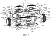
- the present embodiment provides a self-balancing vehicle 600.
- the self-balancing vehicle 600 provided in the present embodiment comprises a vehicle body 610 and two wheels 620 installed on two opposite sides of the vehicle body 610, wherein the self-balancing vehicle 600 also comprises a supporting frame 630 and two driving apparatuses 640 used to control the rotation of wheels 620.
- Two driving apparatuses 640 respectively correspond to two wheels 620.
- the vehicle body 610 comprises an upper shell 6101 and a bottom shell 6102 connected with the upper shell 6101.
- the upper shell 6101 and the bottom shell 6102 are enclosed to form an inner space 610a for containing the supporting frame 630.
- Each driving apparatus 640 comprises a hub motor 641, a control component 642 and a driving component 643.
- the hub motor 641 is installed in each wheel 620 and has a connecting shaft 641a.
- the connecting shaft 641a is rotatably supported on the supporting frame 630.
- the control component 642 comprises a swinging bracket 6421 which is connected with the connecting shaft 641a in a relative non-rotation manner, and a pedal 6423 fixed and connected above the swinging bracket 6421 and used for treading on.
- the driving component 643 is installed in the inner space.
- the driving component 643 comprises a control board 6431 used for enabling the hub motors 641 to rotate when the pedal 6423 rotates around the axis of the connecting shaft 641a relative to the vehicle body 610.
- the control board 6431 is electrically connected with the hub motors 641.
- the support frame 630 has two swinging bracket empty slots 631 for housing the swinging brackets 6421. Two swinging bracket empty slots 631 and two swinging brackets 6421 respectively correspond to each other.
- the vehicle body 610 adopts an integral structure.
- the pedals 6423 are fixed and connected to the swinging brackets 6421.
- the swinging bracket 6421 and the connecting shaft 641a are connected in a relative non-rotation manner.
- the pedals 6423 and the swinging brackets 6421 can swing around the axes of the connecting shafts 641a relative to the vehicle body 610.
- the control board 6431 drives the corresponding wheel 620 to rotate. In this way, the structure of the self-balancing vehicle 600 is smooth, operation is easy, and use safety is good.
- the self-balancing vehicle 600 provided in the present embodiment comprises a vehicle body 610, a left and a right wheels 620, a power supply 650, a supporting frame 630 and a left and a right driving apparatuses 640.
- the vehicle body 610 has an integrated structure. Wheels 620 are respectively installed on the left side and the right side. Each wheel 620 is respectively connected with the vehicle body 610 through a driving apparatus 640.
- the vehicle body 610 comprises an upper shell 6101 and a bottom shell 6102.
- the upper shell 6101 and the bottom shell 6102 are connected and fixed with each other through all existing fixed connection modes such as screws, clamping and the like, and an inner space 610a is encircled by the upper shell 6101 and the bottom shell 6102.
- the supporting frame 630 can be made of aluminum alloy material.
- the supporting frame 630 and a power supply 650 are fixed in the inner space 610a.
- the supporting frame 630 and the upper shell 6101 are connected and fixed.
- the power supply 650 provides electric power for all electrical apparatus elements of the entire vehicle.
- Each driving apparatus 640 comprises a hub motor 641, a control component 642 and a driving component 643.
- the number of the power supply 650 is, but not limited to one.
- One power supply 650 is adopted for respectively supplying power for two hub motors 641 and two driving components 643.
- the power supply 650 can be provided with a charging interface (not shown in the figure).
- the hub motor 641 are installed in the corresponding wheel 620 and have connecting shafts 641a.
- the connecting shafts 641a extend to the inner space 610a of the vehicle body 610 and can be rotatably installed on the supporting frame 630.
- the control component 642 comprises a swinging bracket 6421 and a pedal 6423 for treading on.
- the swinging bracket 6421 and the connecting shaft 641a are connected in a relative non-rotation manner, and are connected and fixed above the swinging bracket 6421.
- Two pedal empty slots 6103 respectively corresponding to two pedals 6423 are formed in a surface of the upper shell 6101.
- the pedals 6423 are installed in the pedal empty slots 6103 and at least partially installed through the surface of the upper shell 6101.
- the wheels 620 are rotatably installed on the supporting frame 630 of the vehicle body 610 through the connecting shafts 641a of the hub motors 641. Driven by the hub motors 641, the wheels 620 rotate and fore-and-aft movement and left-and-right turning of the vehicle body 610 are realized.
- the connecting shafts 641a are rotatably installed on the supporting frames 630.
- the swinging bracket 6421 and the connecting shaft 641a are connected in a relative non-rotation manner. Namely, the pedals 6423 and the swinging brackets 6421 can swing forward and backward around the axes of the connecting shafts 641a relative to the vehicle body 610 by a preset angle. Then, the rotating speed of the hub motors 641 is correspondingly controlled according to the change of the swinging angle of the pedals 6423.
- the driving components 643 comprise a control board 6431 and a plurality of sensors (not shown in the figure).
- the control board 6431 is electrically connected with a plurality of sensors, a power supply 650 and corresponding hub motors 641.
- the control board 6431 can be any existing circuit board capable of controlling the corresponding hub motors 641 to drive the corresponding wheels 620 to rotate according to sensing signals transmitted by the sensors.
- the plurality of sensors are, but not limited to gyroscopes and acceleration sensors.
- the self-balancing vehicle 600 provided in the present embodiment adopts a self-balance principle; the pedals 6423 are installed by a preset angle through the gyroscopes; the pedals 6423 are automatically reset when not tread on through the connecting shafts 641a of the hub motors 641, so that the surfaces of the pedals 6423 are basically parallel with a horizontal plane; the acceleration sensors and the gyroscopes jointly detect the movement state of the self-balancing vehicle 600; and the control board 6431 receives sensing signals of the acceleration sensors and the gyroscopes to control whether the hub motors 641 change states, to realize acceleration or deceleration.
- each connecting shaft 641a is connected to the supporting frame 630 through two groups of bearing components 611.
- the two groups of bearing components 611 are respectively installed on two opposite sides of the swinging bracket 6421.
- Each group of bearing components 611 comprises a pressing block 6111 fixed to the supporting frame 630, and a bearing 6112 sleeved on the connecting shaft 641a.
- the bearing 6112 is installed between the pressing block 6111 and the supporting frame 630.
- two bearings 6112 are sleeved on each connecting shaft 641a.
- a connecting slot 6424 through which the connecting shaft 641a is installed is formed in the swinging bracket 6421.
- Two bearings 6112 are respectively located on the left side and the right side of the swinging bracket 6421. Each bearing 6112 is assembled to the supporting frame 630 through the pressing block 6111. The pressing block 6111 is locked to the supporting frame 630 through screws and other fasteners, and then the connecting shafts 641a of the hub motors 641 are rotatably installed on the supporting frame 630.
- each connecting shaft 641a is provided with a limiting component 612 for limiting the connecting shaft 641a to separate from the supporting frame 630.
- the limiting component 612 comprises two limiting members 6121 respectively fixed to the connecting shaft 641a.
- the bearings 6112 are installed between two limiting members 6121.
- the limiting members 6121 are, but not limited to clamping springs.
- An outer diameter of each clamping spring is larger than an inner diameter of each bearing 6112.
- Two clamping slots (not shown in the figure) are formed in the connecting shaft 641a.
- the two clamping slots are respectively located at two end parts of the connecting shaft 641a.
- the clamping springs are clamped in the corresponding clamping slots, thereby limiting the movement of the connecting shaft 641a in an axial direction, to prevent separation of the connecting shaft 641a from the supporting frame 630.
- an illuminating apparatus 660 is installed on the front side of the vehicle body 610.
- the self-balancing vehicle 600 also comprises an illuminating control apparatus 670.
- the illuminating control apparatus 670 comprises a driving plate (not shown in the figure), a photosensitive sensor 671, a status indicator lamp plate 672 and a power switch 673.
- the photosensitive sensor 671, the status indicator lamp plate 672 and the power switch 673 are installed on the upper shell 6101.
- the driving plate is installed and fixed on the supporting frame 630.
- the status indicator lamp plate 672 is respectively and electrically connected with the photosensitive sensor 671 and the illuminating apparatus 660.
- a front lamp empty slot 6104 is formed in the front side of the upper shell 6101.
- the illuminating apparatus 660 is installed in the inner space 610a.
- the illuminating apparatus 660 comprises a front lamp fixing frame 661, two high-power lamp beads 662 installed on the front lamp fixing frame 661, and a front lamp cover 663.
- the front lamp cover 663 is connected and fixed with the front lamp fixing frame 661 and covers the lamp beads 662.
- the front lamp cover 663 may be a PVC transparent board or a glass board.
- the front lamp cover 663 is exposed to the vehicle body 610 from the front lamp empty slot 6104.
- a surface cover empty slot 6105 is installed in the middle of the upper surface of the upper shell 6101.
- the status indicator lamp plate 672 is installed in the surface cover empty slot 6105.
- the photosensitive sensor 671 and the power switch 673 are installed on a front surface of the status indicator lamp plate 672 (i.e, the upper surface in the figure).
- the driving board can be any existing circuit board capable of controlling the illuminating apparatus 660 to operate according to sensing signals of the photosensitive sensor 671. In this way, when the user uses the self-balancing vehicle 600, according to intensity of light rays, the illuminating control apparatus 670 can control to turn on and to turn off a front lamp.
- a tail lamp component 680 is installed at the rear side of the vehicle body 610.
- the tail lamp component 680 comprises lamp bars 681 and a tail lamp cover 682 that covers outer sides of the lamp bars 681.
- the lamp bars 681 are electrically connected with the control board 6431.
- the tail lamp component 680 is installed on the rear side of the vehicle body.
- the number of the lamp bars 681 is, but not limited to two.
- Two lamp bars 681 respectively correspond to two wheels 620.
- Each lamp bar 681 is electrically connected to corresponding control boards 6431, thereby reflecting a travel state of the self-balancing vehicle 600 through different display states under the control of the control boards 6431 to remind surrounding people and enhancing use safety.
- two lamp bars 681 can present simultaneous normal illumination and flashing or only one lamp bar 681 normally illuminates, flashes or does not illuminate so as to communicate travel state information for surrounding people.
- fender components 690 are respectively installed on two opposite sides of the vehicle body 610.
- Each fender component 690 comprises a fender 691 covered on the corresponding wheel 620, and a bent connecting piece 692.
- the connecting piece 692 comprises two folding edges vertical to each other. One folding edge is connected and fixed with the fender 691, and the other one is connected and fixed with the supporting frame 630.
- the connecting piece 692 is an approximately L-shaped structural bending plate and comprises two folding edges.
- the two folding edges respectively include a first folding edge 6921 of a fixing hole 6923 and a second folding edge 6922 connected with the first folding edge 6921.
- An inserting slot 6911 for containing the second folding edge 6922 is formed in the fender 691.
- a connecting sheet 6912 is formed at one side of the fender 691 near the vehicle body 610.
- a through hole corresponding to the fixing hole 6923 is formed in the connecting sheet 6912. Screws and other fasteners successively penetrate through the fixing hole 6923 and the through hole to fixedly install the connecting piece 692 and the fender 691 on the supporting frame 630.
- a pedal pad 613 is respectively covered on each pedal 6423.
- the pedal pad 613 is fixed to the upper shell 6101.
- the pedal pad 613 is made of flexible material and a surface of the pedal pad 613 can be designed with a skid-proof structure. In this way, certain protection can be performed for the pedal 6423.
- frictional force with the vehicle body 610 can be increased and use safety is enhanced.
- a loudspeaker 614 is fixed to the bottom shell 6102.
- a bluetooth plate (not shown in the figure) is fixed to the supporting frame 630.
- the loudspeaker 614 is electrically connected with the bluetooth plate so as to communicate with outside devices and then enable the loudspeaker 614 to play audio files.
- the connecting shaft 641a and the swinging bracket 6421 are connected through a limiting flat key 615.
- a limiting hole for partially placing the limiting flat key 615 is formed in the connecting shaft 641a.
- a limiting groove corresponding to the limiting hole is formed in the swinging bracket 6421 in the inner wall of the connecting slot 6424.
- the limiting flat key 615 is adopted so that the connecting shaft 641a and the swinging bracket 6421 are connected in a relative non-rotation manner, so that the swinging bracket 6421 and the pedal 6423 can realize forward and backward swing relative to the vehicle body 610.
- each wheel comprises a fixing shaft pivoted to the vehicle body and a rotor-driven wheel connected to the fixing shaft.
- the vehicle body can rotate around the rotor-driven wheel relative to the fixing shaft.
- the driving components are fixed and connected to the fixing shafts.
- the driving components can swing with the fixing shafts relative to the vehicle body.
- the driving components and the wheels are in the same operating plane. Namely, in a using process, the user treads on the wheels, thereby eliminating interference of a balance state of the vehicle body to an output signal of the driving components, i.e., an entire driving mode of the self-balancing vehicle is only stimulated by a balance signal source of the driving components relative to the horizontal plane.
- the user only needs to operate and control the driving components so as to generate an angle relative to the horizontal plane, thereby sending a driving signal to the corresponding rotor-driven wheel to obtain a corresponding travel state.
- This connection mode enhances the sensitivity of the driving components for judging the balance signal, so that the user is easy to operate and especially easy to get on the vehicle, the vehicle body structure is simplified and production cost is reduced.
- the driving components are connected with the supporting shafts. Because the driving components can rotate around axes of the supporting shafts relative to the vehicle body with an external force, the driving components and the vehicle body can rotate in a mutually independent way. Through the openings formed in the vehicle body, both feet of the user can directly control the driving components to incline forwards or backwards. As the driving components do not need to rotate with the vehicle body, rotation of the driving components is sensitive, and then a control signal is sent sensitively to enable the motors to change rotation states rapidly.
Landscapes
- Engineering & Computer Science (AREA)
- Mechanical Engineering (AREA)
- Motorcycle And Bicycle Frame (AREA)
Description
- The present invention relates to the technical field of electric vehicles, and more specifically, to a self-balancing vehicle.
- A self-balancing vehicle is also called as a motion sensing vehicle or an electric personal assistive mobility device. The self-balancing vehicle has an operation principle as follows: change of a self-balancing of a vehicle body is detected by using a gyroscope and an acceleration sensor inside the vehicle body; and a motor is accurately driven by using a servo control system to ensure balance of the vehicle body.
- At present, a control mode of the self-balancing vehicle is as follows: a control pedal is installed on a pedaling region of the vehicle body; advancing, backing, turning and stop of the vehicle body are completed by a user through different applied forces on a front end and a rear end of the control pedal, i.e., a "foot control" mode. However, the control pedal can only move along with the vehicle body but fails to move relative to the vehicle body, so induction sensitivity is low, causing that actual operation and control of the user are difficult and balance experience is poor. Especially, it is difficult to keep stable driving of the vehicle body in a process of getting on the vehicle. A Chinese application (
CN105270526A ) discloses a two-wheel electric balance car. A connecting main body is partially overlaid together with a left supporting module and a right supporting module, respectively; a plurality of elastic devices in a vertical direction are arranged; at least one elastic device is arranged in a front end position between the connecting main body and the right supporting module; at least one elastic device is arranged in a rear end position between the connecting main body and the right supporting module; at least one elastic device is arranged in a front end position between the connecting main body and the left supporting module; and at least one elastic device is arranged in a rear end position between the connecting main body and the left supporting module. Another Chinese application (CN105644672A ) discloses an electric vehicle. The electric vehicle comprises a cabin, two vehicle wheels, a first pedal, a second pedal, a first sensor, a second sensor, a control system and a power source, wherein the two vehicle wheels are installed to the two sides of the cabin through axles; the first pedal and the second pedal can rotate relative to be cabin; the first sensor is used for detecting rotation information of the first pedal; the second sensor is used for detecting rotation information of the second pedal; the control system is connected with the first sensor and the second sensor and is used for controlling the two vehicle wheels to accelerate or decelerate correspondingly; the power source is installed in the cabin; and the cabin is fixedly arranged relative to the axles. An American application (US2013/248573A1 ) discloses a backpack type bag with a self-balancing electric vehicle mounted thereon that includes: two wheels each having a motor mounted thereon; a foot board mounted on the top surface of each motor; a support rod fixed on the foot boards; a housing disposed on one side of the support rod for accommodating batteries and a controller thereinto; a handle mounted on the top portion of the support rod in such a manner as to be inserted and drawn into/from the support rod; and a bag adapted to encompass the support rod and the housing, whereby the bag into which a user's items are put is carried on the user's shoulders, and in a state where the bag is placed above the wheels, the user rides the self-balancing electric vehicle after his feet place on the foot boards. -
CN 105 644 672 A discloses the following features of claim 1; a self-balancing board vehicle, comprising:a vehicle body;two hub motors oppositely installed;two supporting shafts each respectively corresponding to one of the two motors; and two driving components; two wheel bodies are connected to rotors of the respective hub motors; the two hub motors are respectively installed on the left side and the right side of the vehicle body; the two driving components are installed in the vehicle body; one driving component is located on the left side in the vehicle body, and the other driving component is located on the right side in the vehicle body; the two driving components are respectively connected to the two supporting shafts; the left driving component is electrically connected with the left hub motor and controls the left hub motor to rotate, and the right driving component is electrically connected with the right hub motor and controls the right hub motor to rotate; openings corresponding to the driving components are formed in the vehicle body, through the openings formed in the vehicle body, the driving components is capable of rotating around axes of the supporting shafts relative to the vehicle body under action of external force; the driving components rotate, so as to incline forwards or incline backwards relative to a horizontal plane, through the openings formed in the vehicle body, both feet of a user is capable of directly controlling the driving components to incline forwards or incline backwards. - In conclusion, the purpose of embodiments of the present invention is to provide a self-balancing vehicle, in order to overcome problems of difficult operation and low induction sensitivity in using the control pedal to operate and control the self-balancing vehicle in the prior art.
- Embodiments of the present invention are disclosed in the appended claims.
- Compared with the prior art, in the self-balancing vehicle provided in embodiments of the present invention, each wheeler comprises a fixing shaft pivoted to the vehicle body and a rotor-driven wheel connected to the fixing shaft. The vehicle body can rotate around the rotor-driven wheel relative to the fixing shaft. The driving components are fixedly connected to the fixing shafts. The driving components can swing with the fixing shafts opposite to the vehicle body. In this way, the driving components and the wheels are in the same operating plane. Namely, in a using process, a user treads on the wheelers, thereby eliminating interference of a balance state of the vehicle body to an output signal of the driving components, i.e., an entire driving mode of the self-balancing vehicle is only stimulated by a balance signal source of the driving components relative to the horizontal plane. Therefore, the user only needs to operate and control the driving components so as to generate an angle relative to the horizontal plane, thereby sending a driving signal to the corresponding rotor-driven wheel to obtain a corresponding travel state. This connection mode enhances the sensitivity of the driving components for judging the balance signal, so that the user is easier to operate and especially easier to get on the vehicle, thereby simplifying the vehicle body structure and reducing production cost.
-
-
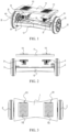
Fig. 1 is an exploded view of a self-balancing vehicle provided in an embodiment 1 of the present invention; -
Fig. 2 is a rear view ofFig. 1 ; -
Fig. 3 is a top view of a self-balancing vehicle provided in an embodiment 1 of the present invention; -
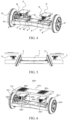
Fig. 4 is another exploded view of a self-balancing vehicle provided in an embodiment 1 of the present invention; -
Fig. 5 is a main view of a self-balancing vehicle provided in an embodiment 2 of the present invention; -
Fig. 6 is a stereoscopic structural schematic diagram of a self-balancing vehicle provided in anembodiment 3 of the present invention; -
Fig. 7 is an enlargement view of VII position inFig. 6 ; -
Fig. 8 is a lateral structural schematic diagram of a self-balancing vehicle provided in anembodiment 3 of the present invention; and -
Fig. 9 is a lateral structural schematic diagram of a self-balancing vehicle provided in an embodiment 4 of the present invention. - To clarify purposes, technical solutions as well as advantages of the present invention clear, the present invention will be further described in detail below in combination with drawings and embodiments. It should be understood that specific embodiments described herein arc only used for explaining the present invention, which is solely defined by the appended claims.
- The application details of the present invention are described below in combination with specific embodiments.
- A self-balancing vehicle comprises: a vehicle body, two wheels pivoted to the vehicle body, pedals installed on the vehicle body, and two driving components installed in the vehicle body which drives the wheels to rotate through the pedals. Wherein each of the wheels comprises a fixing shaft pivoted to the vehicle body and a rotor-driven wheel connected to the fixing shaft. Each of two driving components is electrically connected to its respective rotor-driven wheel. Two driving components are installed in parallel with a certain interval in the vehicle body and respectively fixed and connected to the fixing shafts of their corresponding rotor-driven wheels. When there is an inclined angle generated between each driving component and the horizontal plane, a driving signal is output to the corresponding rotor-driven wheel so that the driving components tend to achieve a dynamic balancing status.
- A self-balancing vehicle provided in embodiments of the present invention has the following operation principle: each wheel comprises a fixing shaft pivoted to the vehicle body and a rotor-driven wheel connected to the fixing shaft. The vehicle body can rotate around the fixing shaft relative to the rotor driving wheel . The driving components are fixedly connected to the fixing shafts. The driving components can swing with the fixing shafts opposite to the vehicle body. In this way, the driving components and the wheels are in the same operating plane. Namely, in a using process, a user treads on the wheelers, thereby eliminating interference of a balance state of the vehicle body to an output signal of the driving components, i.e., an entire driving mode of the self-balancing vehicle is only stimulated by a balance signal source of the driving components relative to the horizontal plane. Therefore, the user only needs to operate and control the driving components so as to generate an angle relative to the horizontal plane, thereby sending a driving signal to the corresponding rotor driving wheel to obtain a corresponding travel state. This connection mode enhances the sensitivity of the driving components for judging the balance signal, so that the user is easier to operate and especially easier to get on the vehicle, thereby simplifying the vehicle body structure and reducing production cost.
- By referring to
Fig. 1, Fig.2 and Fig. 3 , a self-balancing vehicle provided in embodiments of the present invention comprises a vehicle body 1, two wheels 2 pivoted to the vehicle body 1,pedals 111 installed on the vehicle body 1, and twodriving components 3, installed in the vehicle body 1, to drive the two wheels 2 to rotate with the movement of thepedals 111. Each wheel 2 comprises afixing shaft 21 pivoted to the vehicle body 1 and a rotor-drivenwheel 22 connected to thefixing shaft 21. Each of the twodriving components 3 is electrically connected to its respective rotor-drivenwheel 22. Twodriving components 3 are installed in the vehicle body 1 at an interval in parallel and are respectively fixed and connected to thefixing shafts 21 corresponding to the rotor-drivenwheels 22. When there is an inclined angle generated between eachdriving component 3 and a horizontal plane, a driving signal is output to the corresponding rotor-drivenwheel 22 so that thedriving components 3 tend to achieve a dynamic balance. The operation principle is as follows: The vehicle body 1 can rotate around thefixing shaft 21 opposite to the rotor-drivenwheel 22. Thedriving components 3 are fixed and connected to thefixing shafts 21. Thedriving components 3 can swing with thefixing shafts 21 opposite to the vehicle body 1. In this way, thedriving components 3 and the wheels 2 are in the same operating plane. Namely, in a using process, a user treads on the wheels 2, thereby eliminating interference of a balance state of the vehicle body 1 to an output signal of thedriving components 3, i.e., an entire driving mode of the self-balancing vehicle is only stimulated by a balance signal source of thedriving components 3 relative to the horizontal plane. Therefore, the user only needs to operate and control thedriving components 3 so as to generate an inclined angle with the opposite horizontal plane, thereby sending a driving signal to the corresponding rotor-drivenwheel 22 to obtain a corresponding travel state. This connection mode enhances the sensitivity of thedriving components 3 for judging the balance signal, so that the user is easy to operate and especially easy to get on the vehicle, and meanwhile, the vehicle body structure of the self-balancing vehicle is simplified and production cost of a product is reduced. Specifically, by referring toFig. 1, Fig.2 and Fig. 3 in the present embodiment, tworotor driving wheels 22 are respectively installed on both sides of the vehicle body 1, and are mutually parallel. Two drivingcomponents 3 are located between the two rotor-drivenwheels 22. In this way, space between the tworotor driving wheels 22 is long, enabling the vehicle body 1 advancing stable in a traveling process and in a turning process. - Further, by referring to
Fig. 1, Fig.2 and Fig. 3 , in the present embodiment, drivingcomponents 3 comprise ahorizontal plate 31 coupled with the driving component, installed in the vehicle body 1, fixed and connected to the fixingshaft 21, twoelastic pieces 32 respectively installed at a front end of thehorizontal plate 31 and a rear end of thehorizontal plate 31, and a control system 33 rotating along with thehorizontal plate 31. The control system 33 is electrically connected with therotor driving wheels 22. When there is a angle between thehorizontal plate 31 and the horizontal plane, the control system 33 moves together with thehorizontal plate 31, thereby outputting a driving signal to the correspondingrotor driving wheel 22 and realizing rotating acceleration of therotor driving wheels 22, so that thehorizontal plate 31 has a trend of being parallel to the horizontal plane, and theelastic pieces 32 installed on the front end and the rear end of thehorizontal plate 31 regulates a rotating angle of thehorizontal plate 31 relative to the vehicle body 1 to ensure that thehorizontal plate 31 does not generate a too large angle relative to the horizontal plane. Specifically, When the user stands on thepedals 111 of the vehicle body 1 with both feet inclining forwards, correspondinghorizontal plates 31 in the vehicle body 1 are triggered, so that twohorizontal plates 31 generate angles of forward inclining with the horizontal plane and the twohorizontal plates 31 drive the corresponding control system 33 to generate a forward inclined angle relative to the vehicle body 1. An inductor (not shown in the figure) in the control system 33 detects forward inclining movement signals of the twohorizontal plates 31. At this moment, two control systems 33 output forward rotation driving signals to respectiverotor driving wheels 22 to rotate forwards, and the entire self-balancing vehicle moves forwards. Similarly, when the user stands on thepedals 111 of the vehicle body 1 with both feet inclined backwards, correspondinghorizontal plates 31 in the vehicle body 1 are triggered, so that twohorizontal plates 31 generate angles of backward inclining with the horizontal plane and the twohorizontal plates 31 drive the corresponding control system 33 to generate a backward inclined angle relative to the vehicle body 1. An inductor (not shown in the figure) in the control system 33 detects backward inclining movement signals of the twohorizontal plates 31. At this moment, two control systems 33 output backward rotation driving signals to respectiverotor driving wheels 22 to rotate backwards, and the entire self-balancing vehicle moves backwards. When an angle of a lefthorizontal plate 31 relative to the horizontal plane is larger than that of a righthorizontal plate 31 relative to the horizontal plane, the left control system 33 outputs a rapid rotating signal to the leftrotor driving wheel 22, so that the leftrotor driving wheel 22 rotates more rapidly; the right control system 33 outputs a slow rotating signal to the rightrotor driving wheel 22, so that the rightrotor driving wheel 22 rotates more slowly, so as to realize right turning of the entire self-balancing vehicle. Similarly, when a rotating inclined angle of a righthorizontal plate 31 relative to the vehicle body 1 is larger than that of a lefthorizontal plate 31 relative to the vehicle body 1, the entire self-balancing vehicle turns left. Preferably, by referring to the figure, in the present embodiment, theelastic piece 32 is a spring. The rotation of thehorizontal plate 31 relative to the vehicle body 1 is limited through elasticity of the spring. Preferably, the control system 33 is installed underneath thehorizontal plate 31 and rotates together with thehorizontal plate 31. Of course, the control system 33 can also be installed in other positions of thehorizontal plate 31 as long as the inclined angle of thehorizontal plate 31 relative to the horizontal plane is detected. - Or, not shown in the figure, the difference from the above embodiment is that two
elastic pieces 32 are installed in the vehicle body 1 and when thehorizontal plate 31 rotates around the fixingshaft 21, the front end or the rear end of thehorizontal plate 31 touches against theelastic pieces 32 to limit a rotating angle of thehorizontal plate 31 relative to the vehicle body 1. - Further, by referring to
Fig. 1, Fig.2 and Fig. 3 , in the present embodiment, a first supportingseat 41 for supporting the fixingshaft 21 is installed in the vehicle body 1. Afirst bearing 411 is installed in the first supportingseat 41. The fixingshaft 21 is installed throughout thefirst bearing 411. In this way, only one part of the fixingshaft 21 is pivoted to the vehicle body 1 so that thehorizontal plate 31 installed on the fixingshaft 21 is flexible. - Or, by referring to
Fig. 1, Fig.2, Fig. 3 andFig. 4 , in the present embodiment, a second supportingseat 42 for supporting the fixingshaft 21 is also installed in the vehicle body 1. The second supportingseat 42 and the first supportingseat 41 are oppositely installed. A second bearing 421 is installed in the second supportingseat 42. The fixingshaft 21 is respectively installed throughout thefirst bearing 411 and the second bearing 421 and is between the first supportingseat 41 and the second supportingseat 42. In this way, the stability of the fixingshaft 21 between the first supportingseat 41 and the second supportingseat 42 is enhanced, and the operation process of thehorizontal plate 31 installed on the fixingshaft 21 is smooth. - Further, by referring to
Fig. 1, Fig 2 and Fig. 3 in the embodiments, the vehicle body 1 comprises atop housing 11 and abottom housing 12 which are buckled vertically.Pedals 111 are two flexible pedal regions installed on thetop housing 11 and corresponding to the drivingcomponents 3 vertically. In this way, when the user stands on the flexible pedal regions with both feet, it is equivalent to indirectly step on the drivingcomponents 3, thereby realizing operation and control on the drivingcomponents 3. Preferably, the flexible pedal regions are made of flexible silicone gel for the convenience of the user to transmit action force to the drivingcomponents 3. - Specifically, by referring to
Fig. 1, Fig.2 and Fig. 3 , in the present embodiment, the flexible pedal regions are provided with skid-proof grains 11a. In this way, frictional force between the feet and the flexible pedal regions is increased, to prevent slipping. - By referring to
Fig. 5 , the self-balancing vehicle provided in the present embodiment is similar to that in embodiment 1. The differences are that in the present embodiment:
the two rotor-driven wheels 22' are installed in the vehicle body 1', and present an acute angle between each wheels. Two driving components 3' are respectively located at outer sides of the two rotor-driven wheels 22'. Namely, a spacing between upper ends of the two rotor-driven wheels 22' is larger than a spacing between lower ends of the two rotor-driven wheels 22'. In this way, a spacing between the two rotor- driven wheels 22' is reduced so that a turning radius of the self-balancing vehicle is smaller, which enables the vehicle suitable for travel in a narrow space. - Contents not described in the present embodiment are the same as those of embodiment 1, and are not repeated herein.
- By referring to
Fig. 6, Fig. 6 is a stereoscopic structural schematic diagram of a self-balancingvehicle 500 provided in the present embodiment. The self-balancingvehicle 500 comprises a vehicle body 510, motors, supportingshafts 530 and drivingcomponents 540. The motors can adopt inner rotor motors, and can also adopt outer rotor motors. In the present embodiment, the motors are the outer rotor motors, and specifically arehub motors 520.Wheel bodies 521 are connected to rotors of thehub motors 520. Twohub motors 520 are respectively installed on the left side and the right side of the vehicle body 510. Two supportingshafts 530 are coaxially connected with stators of the twohub motors 520 respectively. The supportingshafts 530 are also simultaneously connected with the vehicle body 510 rotatably. In this way, the vehicle body can rotate relative to thehub motors 520. Two drivingcomponents 540 are installed in the vehicle body 510. Onedriving component 540 is located on the left side in the vehicle body 510, and theother driving component 540 is located on the right side in the vehicle body 510. The two drivingcomponents 540 are respectively connected to the two supportingshafts 530. Meanwhile, theleft driving component 540 is electrically connected with theleft hub motor 520, and theright driving component 540 is electrically connected with theright hub motor 520. Openings (not shown in the figure) corresponding to the drivingcomponents 540 are formed in the vehicle body 510. Through the openings formed in the vehicle body 510, the drivingcomponents 540 can rotate around axes of the supportingshafts 530 relative to the vehicle body under the action of external force. The drivingcomponents 540 rotate, so as to incline forwards or incline backwards relative to the horizontal plane. Through the openings formed in the vehicle body 510, both feet of the user can directly control the drivingcomponents 540 to incline forwards or incline backwards. Because the drivingcomponents 540 do not need to rotate with the vehicle body 510, rotation of the drivingcomponents 540 is more sensitive, and then a control signal is sent more sensitively to enable thehub motors 520 to rapidly realize change of rotation states. In addition, because rotating axes of the drivingcomponents 540 are coaxial with operation axes of thehub motors 520, an inclined angle of the drivingcomponents 540 can be converted more accurately and more simply into the control signal of thehub motors 520, and then rotation of thehub motors 520 is controlled more accurately, so that the user is more convenient to operate and especially easier to get on the vehicle, the structure of self-balancing vehicle body is simplified and production cost is reduced. - When the user inclines the body forwards to enable the two driving
components 540 to incline forwards with basically a same angle, the two drivingcomponents 540 respectively control the twohub motors 520 to rotate forwards basically at a same speed, so that the self-balancingvehicle 500 moves forwards entirely. When the user inclines the body backwards to enable the two drivingcomponents 540 to incline backwards with basically a same angle, the two drivingcomponents 540 respectively control the twohub motors 520 to rotate backwards basically at a same speed, so that the self-balancingvehicle 500 moves backwards entirely. When the user enables the inclined angle of theleft driving component 540 to be larger than the inclined angle of theright driving component 540, rotating speed of theleft hub motor 520 is larger than rotating speed of theright hub motor 520 and then the self-balancingvehicle 500 turns right as a whole. When the user enables the inclined angle of theright driving component 540 to be larger than the inclined angle of theleft driving component 540, rotating speed of theright hub motor 520 is larger than rotating speed of theleft hub motor 520 and then the self-balancingvehicle 500 turns left as a whole. - By referring to
Fig. 7, Fig. 7 is an enlargement view of VII position inFig. 6 . In the present embodiment, drivingcomponent 540 comprises ahorizontal plate 541 coupled with the driving component and a control apparatus 542 connected with thehorizontal plate 541 and moving with thehorizontal plate 541, wherein thehorizontal plate 541 is connected with the supportingshafts 530 and thehorizontal plate 541 is used for rotating with the supportingshafts 530 relative to the vehicle body 510. The control apparatus 542 is electrically connected with the correspondinghub motor 520. The control apparatus 542 is used for controlling the rotation of thehub motors 520 electrically connected with the control apparatus 542 during incline. Thehorizontal plate 541 is used for bearing control force of the user, and then driving the drivingcomponents 540 to incline as a whole. Connection modes between thehorizontal plate 541 and the supportingshafts 530 are diverse, such as welding connection, bolt connection, riveting and the like. In the present embodiment, each drivingcomponent 540 also comprises a fixingpart 543. The fixingpart 543 has a U-shaped structure. Both ends of the fixingpart 543 are connected with thehorizontal plate 541. The fixingpart 543 and thehorizontal plate 541 jointly form a fixing space 544. The supportingshafts 530 is installed through a fixing space 544, so as to connect the drivingcomponents 540 with the supportingshafts 530. A circumferential surface of each supportingshaft 530 comes into contact with the fixingpart 543 and thehorizontal plate 541, so as to prevent the drivingcomponents 540 to generate radial motion relative to the supportingshafts 530. In the present embodiment, to avoid generating relative rotation between the drivingcomponents 540 and the supportingshafts 530, a limitingsurface 531 which extends along an axis is installed on each supportingshaft 530. The limitingsurface 531 is fitted to a plate surface of thehorizontal plate 541. In this way, relative rotation between the drivingcomponents 540 and the supportingshafts 530 can be avoided, and then the operation of the drivingcomponents 540 is more stable and reliable. - By referring to
Fig. 7 and combining withFig. 8, Fig. 8 is a lateral structural schematic diagram of a self-balancingvehicle 500 provided in the present embodiment. In the present embodiment, the drivingcomponents 540 also comprise twoelastic pieces 545 installed on the front side and the rear side of the supportingshafts 530. One end of the twoelastic pieces 545 is respectively connected with the front end and the rear end of thehorizontal plate 541. When thehorizontal plate 541 is inclined forwards, theelastic piece 545 on the front end of thehorizontal plate 541 is touched against the vehicle body 510 to limit the forward inclined angle of thehorizontal plate 541, so that thehorizontal plate 541 will not generate a too large inclined angle forwards. Meanwhile, the elastic piece helps for thehorizontal plate 541 to restore to a horizontal position, thereby enhancing the safety of the self-balancingvehicle 500. When thehorizontal plate 541 is inclined backwards, theelastic piece 545 on the rear end of thehorizontal plate 541 is abutted against the vehicle body 510 to limit the backward inclined angle of thehorizontal plate 541, so that thehorizontal plate 541 will not generate a too large inclined angle backwards. Meanwhile, the elastic piece helps for thehorizontal plate 541 to restore to a horizontal position, thereby enhancing the safety of the self-balancingvehicle 500. It can be understood that in other embodiments, twoelastic pieces 545 can also be connected with the vehicle body 510 and are touched against thehorizontal plate 541 when the horizontal plate is inclined forwards or backwards. In the present embodiment, theelastic pieces 545 are springs. It can be understood that in other embodiments, theelastic pieces 545 can also be other apparatuses having elasticity, such as elastic rubber blocks and the like. - By referring to
Fig. 6 again, the self-balancingvehicle 500 also comprisespedals 550. Thepedals 550 are installed on openings of the vehicle body 510. Thepedals 550 are used for the user to step on. The user drives the drivingcomponents 540 through thepedals 550 to rotate. To realize the function, thepedals 550 can be pivoted to the openings of the vehicle body 510. Thepedals 550 can also be installed and fixed at the openings of the vehicle body 510, and thepedals 550 are made of flexible material. In this way, when the user applies force to thepedals 550, thepedals 550 are deformed, and then drive thehorizontal plate 541 to incline forwards or backwards. Thepedals 550 are installed and fixed at the openings of the vehicle body 510, thereby enhancing the entire sealing property of the self-balancingvehicle 500. - By referring again to
Fig. 7 , in the present embodiment, a supportingseat 560 is respectively installed on the left side and the right side in the vehicle body 510.Bearings 570 are installed in the supportingseats 560. The supportingshafts 530 are installed through thebearings 570 in the corresponding supportingseats 560. The supportingshafts 530 are supported through the supportingseats 560 and thebearings 570, so as to enhance the bearing capability of the supportingshafts 530. Meanwhile, the supportingshafts 530 can rotate more smoothly. In the present embodiment, each supportingseat 560 comprises a seat body 561 fixed and connected with the vehicle body 510, and a cover body 562 detachably connected with the seat body 561. Semicircular accommodating grooves (not shown in the figure) are respectively formed in the seat body 561 and the cover body 562. Thebearings 570 are embedded into the accommodating grooves in the seat body 561 and the cover body 562. Then, the seat body 561 and the cover body 562 are connected together. In this way, thebearings 570 are firmly installed on the supportingseats 560. In the present embodiment, the seat body 561 and the cover body 562 are connected through bolts. - In the present embodiment, two
hub motors 520 are respectively installed on the left side and the right side of the vehicle body 510. In other embodiments, twohub motors 520 can also be oppositely installed in the vehicle body 510, and are located between two drivingcomponents 540. In this way, the spacing between the twohub motors 520 is shortened, so that a turning radius of the self-balancingvehicle 500 is smaller, which is suitable for travel in a narrow space. In this case, twohub motors 520 are located between both feet of the user during use. To avoid friction between thehub motors 520 and legs of the user, twohub motors 520 can be obliquely installed. Axes of the twohub motors 520 are intersected and form an included angle, so that a spacing between upper ends of the twohub motors 520 is larger than a spacing between lower ends of the twohub motors 520. In this way, more space is reserved for a user's legs , thereby avoiding friction between thehub motors 520 and legs of the user, and enhancing safety. - By referring to
Fig. 9 , the present embodiment provides a self-balancing vehicle 600. The self-balancing vehicle 600 provided in the present embodiment comprises avehicle body 610 and twowheels 620 installed on two opposite sides of thevehicle body 610, wherein the self-balancing vehicle 600 also comprises a supportingframe 630 and two drivingapparatuses 640 used to control the rotation ofwheels 620. Two drivingapparatuses 640 respectively correspond to twowheels 620. Thevehicle body 610 comprises anupper shell 6101 and abottom shell 6102 connected with theupper shell 6101. Theupper shell 6101 and thebottom shell 6102 are enclosed to form aninner space 610a for containing the supportingframe 630. Each drivingapparatus 640 comprises ahub motor 641, acontrol component 642 and adriving component 643. Thehub motor 641 is installed in eachwheel 620 and has a connectingshaft 641a. The connectingshaft 641a is rotatably supported on the supportingframe 630. Thecontrol component 642 comprises a swingingbracket 6421 which is connected with the connectingshaft 641a in a relative non-rotation manner, and apedal 6423 fixed and connected above the swingingbracket 6421 and used for treading on. Thedriving component 643 is installed in the inner space. Thedriving component 643 comprises acontrol board 6431 used for enabling thehub motors 641 to rotate when thepedal 6423 rotates around the axis of the connectingshaft 641a relative to thevehicle body 610. Thecontrol board 6431 is electrically connected with thehub motors 641. Thesupport frame 630 has two swinging bracket empty slots 631 for housing the swingingbrackets 6421. Two swinging bracket empty slots 631 and two swingingbrackets 6421 respectively correspond to each other. - In the above self-balancing vehicle 600, the
vehicle body 610 adopts an integral structure. Thepedals 6423 are fixed and connected to the swingingbrackets 6421. The swingingbracket 6421 and the connectingshaft 641a are connected in a relative non-rotation manner. Thepedals 6423 and the swingingbrackets 6421 can swing around the axes of the connectingshafts 641a relative to thevehicle body 610. When thepedals 6423 rotate around the axes of the connectingshafts 641a relative to thevehicle body 610, thecontrol board 6431 drives thecorresponding wheel 620 to rotate. In this way, the structure of the self-balancing vehicle 600 is smooth, operation is easy, and use safety is good. - By referring to
Fig. 9 , the self-balancing vehicle 600 provided in the present embodiment comprises avehicle body 610, a left and aright wheels 620, apower supply 650, a supportingframe 630 and a left and aright driving apparatuses 640. Thevehicle body 610 has an integrated structure.Wheels 620 are respectively installed on the left side and the right side. Eachwheel 620 is respectively connected with thevehicle body 610 through adriving apparatus 640. In the present embodiment, thevehicle body 610 comprises anupper shell 6101 and abottom shell 6102. Theupper shell 6101 and thebottom shell 6102 are connected and fixed with each other through all existing fixed connection modes such as screws, clamping and the like, and aninner space 610a is encircled by theupper shell 6101 and thebottom shell 6102. The supportingframe 630 can be made of aluminum alloy material. The supportingframe 630 and apower supply 650 are fixed in theinner space 610a. The supportingframe 630 and theupper shell 6101 are connected and fixed. Thepower supply 650 provides electric power for all electrical apparatus elements of the entire vehicle. Each drivingapparatus 640 comprises ahub motor 641, acontrol component 642 and adriving component 643. The number of thepower supply 650 is, but not limited to one. Onepower supply 650 is adopted for respectively supplying power for twohub motors 641 and two drivingcomponents 643. Thepower supply 650 can be provided with a charging interface (not shown in the figure). - Specifically, the
hub motor 641 are installed in thecorresponding wheel 620 and have connectingshafts 641a. The connectingshafts 641a extend to theinner space 610a of thevehicle body 610 and can be rotatably installed on the supportingframe 630. Thecontrol component 642 comprises a swingingbracket 6421 and apedal 6423 for treading on. The swingingbracket 6421 and the connectingshaft 641a are connected in a relative non-rotation manner, and are connected and fixed above the swingingbracket 6421. Two pedalempty slots 6103 respectively corresponding to twopedals 6423 are formed in a surface of theupper shell 6101. Thepedals 6423 are installed in the pedalempty slots 6103 and at least partially installed through the surface of theupper shell 6101. It is easy to understand that thewheels 620 are rotatably installed on the supportingframe 630 of thevehicle body 610 through the connectingshafts 641a of thehub motors 641. Driven by thehub motors 641, thewheels 620 rotate and fore-and-aft movement and left-and-right turning of thevehicle body 610 are realized. The connectingshafts 641a are rotatably installed on the supporting frames 630. The swingingbracket 6421 and the connectingshaft 641a are connected in a relative non-rotation manner. Namely, thepedals 6423 and the swingingbrackets 6421 can swing forward and backward around the axes of the connectingshafts 641a relative to thevehicle body 610 by a preset angle. Then, the rotating speed of thehub motors 641 is correspondingly controlled according to the change of the swinging angle of thepedals 6423. - The driving
components 643 comprise acontrol board 6431 and a plurality of sensors (not shown in the figure). Thecontrol board 6431 is electrically connected with a plurality of sensors, apower supply 650 andcorresponding hub motors 641. Thecontrol board 6431 can be any existing circuit board capable of controlling the correspondinghub motors 641 to drive the correspondingwheels 620 to rotate according to sensing signals transmitted by the sensors. The plurality of sensors are, but not limited to gyroscopes and acceleration sensors. It is deserved to mention that the self-balancing vehicle 600 provided in the present embodiment adopts a self-balance principle; thepedals 6423 are installed by a preset angle through the gyroscopes; thepedals 6423 are automatically reset when not tread on through the connectingshafts 641a of thehub motors 641, so that the surfaces of thepedals 6423 are basically parallel with a horizontal plane; the acceleration sensors and the gyroscopes jointly detect the movement state of the self-balancing vehicle 600; and thecontrol board 6431 receives sensing signals of the acceleration sensors and the gyroscopes to control whether thehub motors 641 change states, to realize acceleration or deceleration. - By referring to
Fig. 9 , each connectingshaft 641a is connected to the supportingframe 630 through two groups of bearing components 611. The two groups of bearing components 611 are respectively installed on two opposite sides of the swingingbracket 6421. Each group of bearing components 611 comprises apressing block 6111 fixed to the supportingframe 630, and abearing 6112 sleeved on the connectingshaft 641a. Thebearing 6112 is installed between thepressing block 6111 and the supportingframe 630. In the present embodiment, twobearings 6112 are sleeved on each connectingshaft 641a. A connecting slot 6424 through which the connectingshaft 641a is installed is formed in the swingingbracket 6421. Twobearings 6112 are respectively located on the left side and the right side of the swingingbracket 6421. Eachbearing 6112 is assembled to the supportingframe 630 through thepressing block 6111. Thepressing block 6111 is locked to the supportingframe 630 through screws and other fasteners, and then the connectingshafts 641a of thehub motors 641 are rotatably installed on the supportingframe 630. - By referring to
Fig. 9 , each connectingshaft 641a is provided with a limitingcomponent 612 for limiting the connectingshaft 641a to separate from the supportingframe 630. The limitingcomponent 612 comprises two limitingmembers 6121 respectively fixed to the connectingshaft 641a. Thebearings 6112 are installed between two limitingmembers 6121. In the present embodiment, the limitingmembers 6121 are, but not limited to clamping springs. An outer diameter of each clamping spring is larger than an inner diameter of eachbearing 6112. Two clamping slots (not shown in the figure) are formed in the connectingshaft 641a. The two clamping slots are respectively located at two end parts of the connectingshaft 641a. The clamping springs are clamped in the corresponding clamping slots, thereby limiting the movement of the connectingshaft 641a in an axial direction, to prevent separation of the connectingshaft 641a from the supportingframe 630. - By referring to
Fig. 9 , an illuminatingapparatus 660 is installed on the front side of thevehicle body 610. The self-balancing vehicle 600 also comprises an illuminatingcontrol apparatus 670. The illuminatingcontrol apparatus 670 comprises a driving plate (not shown in the figure), a photosensitive sensor 671, a statusindicator lamp plate 672 and apower switch 673. The photosensitive sensor 671, the statusindicator lamp plate 672 and thepower switch 673 are installed on theupper shell 6101. The driving plate is installed and fixed on the supportingframe 630. The statusindicator lamp plate 672 is respectively and electrically connected with the photosensitive sensor 671 and the illuminatingapparatus 660. In the present embodiment, a front lamp empty slot 6104 is formed in the front side of theupper shell 6101. The illuminatingapparatus 660 is installed in theinner space 610a. The illuminatingapparatus 660 comprises a frontlamp fixing frame 661, two high-power lamp beads 662 installed on the frontlamp fixing frame 661, and afront lamp cover 663. Thefront lamp cover 663 is connected and fixed with the frontlamp fixing frame 661 and covers thelamp beads 662. Thefront lamp cover 663 may be a PVC transparent board or a glass board. Thefront lamp cover 663 is exposed to thevehicle body 610 from the front lamp empty slot 6104. A surface coverempty slot 6105 is installed in the middle of the upper surface of theupper shell 6101. The statusindicator lamp plate 672 is installed in the surface coverempty slot 6105. The photosensitive sensor 671 and thepower switch 673 are installed on a front surface of the status indicator lamp plate 672 (i.e, the upper surface in the figure). The driving board can be any existing circuit board capable of controlling the illuminatingapparatus 660 to operate according to sensing signals of the photosensitive sensor 671. In this way, when the user uses the self-balancing vehicle 600, according to intensity of light rays, the illuminatingcontrol apparatus 670 can control to turn on and to turn off a front lamp. - By referring to
Fig. 9 , atail lamp component 680 is installed at the rear side of thevehicle body 610. Thetail lamp component 680 comprises lamp bars 681 and atail lamp cover 682 that covers outer sides of the lamp bars 681. The lamp bars 681 are electrically connected with thecontrol board 6431. In the present embodiment, thetail lamp component 680 is installed on the rear side of the vehicle body. The number of the lamp bars 681 is, but not limited to two. Two lamp bars 681 respectively correspond to twowheels 620. Each lamp bar 681 is electrically connected tocorresponding control boards 6431, thereby reflecting a travel state of the self-balancing vehicle 600 through different display states under the control of thecontrol boards 6431 to remind surrounding people and enhancing use safety. It can be understood that according to the travel states of the self-balancing vehicle 600, such as advancing, retreating, left turning, right turning and the like, two lamp bars 681 can present simultaneous normal illumination and flashing or only one lamp bar 681 normally illuminates, flashes or does not illuminate so as to communicate travel state information for surrounding people. - By referring to
Fig. 9 ,fender components 690 are respectively installed on two opposite sides of thevehicle body 610. Eachfender component 690 comprises afender 691 covered on thecorresponding wheel 620, and a bent connectingpiece 692. The connectingpiece 692 comprises two folding edges vertical to each other. One folding edge is connected and fixed with thefender 691, and the other one is connected and fixed with the supportingframe 630. In the present embodiment, the connectingpiece 692 is an approximately L-shaped structural bending plate and comprises two folding edges. The two folding edges respectively include a first folding edge 6921 of afixing hole 6923 and asecond folding edge 6922 connected with the first folding edge 6921. An insertingslot 6911 for containing thesecond folding edge 6922 is formed in thefender 691. A connectingsheet 6912 is formed at one side of thefender 691 near thevehicle body 610. A through hole corresponding to thefixing hole 6923 is formed in the connectingsheet 6912. Screws and other fasteners successively penetrate through thefixing hole 6923 and the through hole to fixedly install the connectingpiece 692 and thefender 691 on the supportingframe 630. - By referring to
Fig. 9 , apedal pad 613 is respectively covered on eachpedal 6423. Thepedal pad 613 is fixed to theupper shell 6101. Thepedal pad 613 is made of flexible material and a surface of thepedal pad 613 can be designed with a skid-proof structure. In this way, certain protection can be performed for thepedal 6423. In addition, in the use process of the user, frictional force with thevehicle body 610 can be increased and use safety is enhanced. - By referring to
Fig. 9 , aloudspeaker 614 is fixed to thebottom shell 6102. A bluetooth plate (not shown in the figure) is fixed to the supportingframe 630. Theloudspeaker 614 is electrically connected with the bluetooth plate so as to communicate with outside devices and then enable theloudspeaker 614 to play audio files. - By referring to
Fig. 9 , the connectingshaft 641a and the swingingbracket 6421 are connected through a limitingflat key 615. In the present embodiment, a limiting hole for partially placing the limitingflat key 615 is formed in the connectingshaft 641a. A limiting groove corresponding to the limiting hole is formed in the swingingbracket 6421 in the inner wall of the connecting slot 6424. The limitingflat key 615 is adopted so that the connectingshaft 641a and the swingingbracket 6421 are connected in a relative non-rotation manner, so that the swingingbracket 6421 and thepedal 6423 can realize forward and backward swing relative to thevehicle body 610. - In the self-balancing vehicle provided in embodiments of the present invention, each wheel comprises a fixing shaft pivoted to the vehicle body and a rotor-driven wheel connected to the fixing shaft. The vehicle body can rotate around the rotor-driven wheel relative to the fixing shaft. The driving components are fixed and connected to the fixing shafts. The driving components can swing with the fixing shafts relative to the vehicle body. In this way, the driving components and the wheels are in the same operating plane. Namely, in a using process, the user treads on the wheels, thereby eliminating interference of a balance state of the vehicle body to an output signal of the driving components, i.e., an entire driving mode of the self-balancing vehicle is only stimulated by a balance signal source of the driving components relative to the horizontal plane. Therefore, the user only needs to operate and control the driving components so as to generate an angle relative to the horizontal plane, thereby sending a driving signal to the corresponding rotor-driven wheel to obtain a corresponding travel state. This connection mode enhances the sensitivity of the driving components for judging the balance signal, so that the user is easy to operate and especially easy to get on the vehicle, the vehicle body structure is simplified and production cost is reduced.
- In the self-balancing vehicle provided in embodiments of the present invention, the driving components are connected with the supporting shafts. Because the driving components can rotate around axes of the supporting shafts relative to the vehicle body with an external force, the driving components and the vehicle body can rotate in a mutually independent way. Through the openings formed in the vehicle body, both feet of the user can directly control the driving components to incline forwards or backwards. As the driving components do not need to rotate with the vehicle body, rotation of the driving components is sensitive, and then a control signal is sent sensitively to enable the motors to change rotation states rapidly. In addition, because rotating axes of the driving components are coaxial with operation axes of the motors, an inclined angle of the driving components can be converted into the control signal of the motors accurately and simply, and then rotation of the motors is accurate, so that the user is convenient to operate and especially easier to get on the vehicle, the vehicle body structure is simplified and production cost is reduced.
Claims (9)
- A self-balancing board vehicle (500), comprising:a vehicle body (510);two motors (520) oppositely installed;two supporting shafts (530) each respectively corresponding to one of the two motors (520); and two driving components (540), wherein:each driving component (540) is connected with the corresponding supporting shaft (530); the driving components (540) rotate with their respective supporting shafts (530); the motors (520) are outer rotor motors (520), and specifically are hub motors (520); two respective wheel bodies (521) are connected to the rotors of the respective hub motors (520); the two hub motors (520) are respectively installed on the left side and the right side of the vehicle body (510); the two supporting shafts (530) are coaxially connected with a stator of the two respective hub motors (520);the supporting shafts (530) are also simultaneously rotatably connected with the vehicle body (510), so that the vehicle body (510) is capable of rotating relative to the hub motors (520); the two driving components (540) are installed in the vehicle body (510); one driving component (540) is located on the left side in the vehicle body (510), and the other driving component (540) is located on the right side in the vehicle body (510); the two driving components (540) are respectively connected to the two supporting shafts (530);the left driving component (540) is electrically connected with the left hub motor (520) and controls the left hub motor (520) to rotate, and the right driving component (540) is electrically connected with the right hub motor (520) and controls the right hub motor (520) to rotate; openings corresponding to the driving components (540) are formed in the vehicle body (510), through the openings formed in the vehicle body (510), the driving components (540) are capable of rotating around axes of the supporting shafts (530) relative to the vehicle body (510) under action of external force; the driving components (540) rotate, so as to incline forwards or incline backwards relative to a horizontal plane, through the openings formed in the vehicle body (510), both feet of a user are capable of directly controlling the driving components (540) to incline forwards or incline backwards; and the rotating axes of the driving components (540) are coaxial with operation axes of the hub motors (520).
- The self-balancing vehicle according to claim 1, wherein the two motors are respectively installed at two sides of the vehicle body (510, 600).
- The self-balancing vehicle according to claim 1, wherein each of the two driving components (3, 3', 540, 643) comprises a horizontal plate (31, 541) and a control apparatus (542) connected to the horizontal plate (31, 541) and moving with the horizontal plate (31, 541);the horizontal plate is connected with one of the two supporting shafts (530), and the horizontal plate (31, 541) rotates with the one of the two supporting shafts (530) relatively to the vehicle body (1, 1', 510, 600);the control apparatus (542) is electrically connected with one of the two motors, and the control apparatus (542) controls the one of the two motors to rotate during an inclination.
- The self-balancing vehicle according to claim 3, wherein each of the driving components (3, 3', 540, 643) further comprises a fixing part (543);the fixing part (543) is connected with the horizontal plate (31, 541), and jointly confines a fixing space (544) with the horizontal plate (31, 541);each of the supporting shafts (530) penetrates through the fixing space (544).
- The self-balancing vehicle according to claim 4, wherein each of the supporting shafts (530) is provided with a limiting surface (531) extending along an axis of the supporting shaft (530);
the limiting surface (531) is fit with a surface of the horizontal plate (31, 541). - The self-balancing vehicle according to claim 3, wherein each of the driving components (3, 3', 540, 643) further comprises an elastic piece (32, 545) located at two sides of each of the supporting shafts (530);the elastic piece (32, 545) is connected with the horizontal plate (31, 541), and the elastic piece (32, 545) is butted against the vehicle body (1, 1', 510, 600) when the horizontal plate (31, 541) inclines; orthe elastic piece (32, 545) is connected with the vehicle body (1, 1', 510, 600), and the elastic piece (32, 545) part is butted against the horizontal plate when the horizontal plate (31, 541) inclines.
- The self-balancing vehicle according to any one of claims 1-6, wherein the self-balancing vehicle further comprises two supporting seats (41, 42, 560) installed in the vehicle body (1, 1', 510, 600), and bearings are installed in the supporting seats (41, 42, 560);each of the supporting shafts (530) corresponds to at least one of the supporting seats (41, 42, 560);one of the supporting shafts (530) penetrates through one of the bearings installed in a corresponding supporting seat (41, 42, 560).
- The self-balancing vehicle according to any one of claims 1-6, wherein the two motors (520) are located between the two driving components (3, 3', 540, 643).
- The self-balancing vehicle according to claim 8, wherein axes of the two motors (520) intersect and form an intersection angle.
Applications Claiming Priority (2)
| Application Number | Priority Date | Filing Date | Title |
|---|---|---|---|
| CN201610749689.7A CN106275170B (en) | 2016-08-29 | 2016-08-29 | Posture vehicle |
| PCT/CN2017/090922 WO2018040714A1 (en) | 2016-08-29 | 2017-06-29 | Pose vehicle |
Publications (3)
| Publication Number | Publication Date |
|---|---|
| EP3321156A1 EP3321156A1 (en) | 2018-05-16 |
| EP3321156A4 EP3321156A4 (en) | 2018-11-07 |
| EP3321156B1 true EP3321156B1 (en) | 2024-01-24 |
Family
ID=57677003
Family Applications (1)
| Application Number | Title | Priority Date | Filing Date |
|---|---|---|---|
| EP17808299.6A Active EP3321156B1 (en) | 2016-08-29 | 2017-06-29 | Pose vehicle |
Country Status (5)
| Country | Link |
|---|---|
| US (1) | US10583886B2 (en) |
| EP (1) | EP3321156B1 (en) |
| JP (1) | JP6544814B2 (en) |
| CN (1) | CN106275170B (en) |
| WO (1) | WO2018040714A1 (en) |
Families Citing this family (35)
| Publication number | Priority date | Publication date | Assignee | Title |
|---|---|---|---|---|
| USD941948S1 (en) | 2016-07-20 | 2022-01-25 | Razor Usa Llc | Two wheeled board |
| USD803963S1 (en) | 2016-07-20 | 2017-11-28 | Razor Usa Llc | Two wheeled board |
| USD839132S1 (en) * | 2016-08-03 | 2019-01-29 | Radical Transport, Llc | Wheeled vehicle |
| CN106275170B (en) * | 2016-08-29 | 2018-11-13 | 深圳市动平衡科技有限公司 | Posture vehicle |
| CN106515947B (en) * | 2016-12-29 | 2019-01-11 | 杭州畅动智能科技有限公司 | The control method and control system of a kind of body-sensing longitudinal direction cart |
| USD820157S1 (en) * | 2016-12-30 | 2018-06-12 | Hangzhou Lunyu Technology Co., Ltd. | Self-balanced vehicle |
| US11541960B2 (en) * | 2017-01-04 | 2023-01-03 | Hangzhou Chic Intelligent Technology Co., Ltd | Man-machine interaction somatosensory vehicle |
| US12227257B2 (en) * | 2017-04-01 | 2025-02-18 | Razor Usa Llc | Electric balance vehicles |
| CN107097881A (en) * | 2017-04-28 | 2017-08-29 | 深圳市亮点智控科技有限公司 | A kind of control method of posture car and posture car |
| US10926159B1 (en) * | 2017-07-25 | 2021-02-23 | Lean Steer Difference, LLC | Lean-to-steer device with motorized steering responses |
| CN109693747B (en) * | 2017-10-20 | 2022-04-26 | 深圳市亮点智控科技有限公司 | Swing type balance robot and balance robot control method |
| CN108357602A (en) * | 2018-02-13 | 2018-08-03 | 深圳市亮点智控科技有限公司 | A kind of balance car |
| CN208134509U (en) * | 2018-02-28 | 2018-11-23 | 浙江阿尔郎科技有限公司 | The automobile-used rotating mechanism of electrodynamic balance and electrodynamic balance vehicle including the rotating mechanism |
| US20200282295A1 (en) * | 2019-01-09 | 2020-09-10 | Shane Chen | Auto-balancing device with longitudinally disposed and movable platform sections |
| CN111591382A (en) * | 2019-02-02 | 2020-08-28 | 杭州骑客智能科技有限公司 | Human-computer interaction somatosensory vehicle |
| USD890280S1 (en) * | 2019-03-11 | 2020-07-14 | Future Motion, Inc. | Rider detection sensor for electric vehicle |
| USD881307S1 (en) * | 2019-03-11 | 2020-04-14 | Future Motion, Inc. | Fender for electric vehicle |
| USD888175S1 (en) * | 2019-03-11 | 2020-06-23 | Future Motion, Inc. | Electric vehicle front |
| USD881308S1 (en) * | 2019-03-11 | 2020-04-14 | Future Motion, Inc. | Fender for electric vehicle |
| USD890278S1 (en) * | 2019-03-11 | 2020-07-14 | Future Motion, Inc. | Electric vehicle |
| USD897469S1 (en) * | 2019-03-11 | 2020-09-29 | Future Motion, Inc. | Foot pad for electric vehicle |
| USD886929S1 (en) * | 2019-03-11 | 2020-06-09 | Future Motion, Inc. | Rear bumper for electric vehicle |
| USD890279S1 (en) * | 2019-03-11 | 2020-07-14 | Future Motion, Inc. | Electric vehicle with fender |
| US11141647B2 (en) | 2019-05-01 | 2021-10-12 | Bowen Li | Self-balancing vehicle with rotation stop |
| US10421006B1 (en) * | 2019-05-01 | 2019-09-24 | Bowen Li | Self-balancing vehicle and structural support therein |
| CN110329410B (en) * | 2019-08-15 | 2024-04-02 | 应浩通 | Integrated balance car |
| CN111506098A (en) * | 2020-05-08 | 2020-08-07 | 新石器慧通(北京)科技有限公司 | Method for regulating and controlling position and attitude of automatic driving vehicle and carriage |
| KR102362989B1 (en) * | 2020-05-28 | 2022-02-15 | 국민대학교 산학협력단 | Vehicle for assisting drone take-off and landing |
| CN111891274B (en) * | 2020-07-21 | 2022-11-25 | 深圳乐行天下科技有限公司 | Balancing car control method, device and storage medium |
| MX2023008476A (en) | 2021-01-18 | 2023-07-27 | Corey C Smith | TILT STEERING DEVICES WITH ACTIVE STEERING RESPONSES. |
| CN112810716B (en) * | 2021-03-17 | 2025-01-03 | 章征凯 | Posture adjusting device |
| CN113753164A (en) * | 2021-09-07 | 2021-12-07 | 深圳市亮点智控科技有限公司 | Motion sensing vehicle operation control system and method |
| US11299059B1 (en) | 2021-10-20 | 2022-04-12 | Future Motion, Inc. | Self-stabilizing skateboard |
| US12370889B2 (en) * | 2023-01-24 | 2025-07-29 | Gregory L. Hilton | Sensor array system for a motorized board |
| US12545351B2 (en) * | 2023-09-20 | 2026-02-10 | Future Motion, Inc. | Vibrational notification of motor conditions in a self-balancing electric vehicle |
Family Cites Families (37)
| Publication number | Priority date | Publication date | Assignee | Title |
|---|---|---|---|---|
| US6302230B1 (en) * | 1999-06-04 | 2001-10-16 | Deka Products Limited Partnership | Personal mobility vehicles and methods |
| US7275607B2 (en) * | 1999-06-04 | 2007-10-02 | Deka Products Limited Partnership | Control of a personal transporter based on user position |
| JP4411867B2 (en) * | 2003-06-04 | 2010-02-10 | トヨタ自動車株式会社 | Vehicles that can be steered by moving the center of gravity |
| JP2005094858A (en) * | 2003-09-12 | 2005-04-07 | Sony Corp | Traveling apparatus and control method thereof |
| EP1529556B1 (en) * | 2003-11-04 | 2013-02-20 | Toyota Jidosha Kabushiki Kaisha | Travelling apparatus and method for controlling thereof |
| JP4556831B2 (en) * | 2005-10-13 | 2010-10-06 | トヨタ自動車株式会社 | Traveling apparatus and control method thereof |
| JP5147542B2 (en) * | 2008-05-23 | 2013-02-20 | 本田技研工業株式会社 | Inverted pendulum moving body |
| US8170780B2 (en) * | 2008-11-06 | 2012-05-01 | Segway, Inc. | Apparatus and method for control of a vehicle |
| JP2012126224A (en) * | 2010-12-15 | 2012-07-05 | Bosch Corp | Inverted pendulum type moving body |
| US8738278B2 (en) * | 2012-02-12 | 2014-05-27 | Shane Chen | Two-wheel, self-balancing vehicle with independently movable foot placement sections |
| KR20130107684A (en) * | 2012-03-23 | 2013-10-02 | 주식회사 로보쓰리 | The backpack type a bag with self balancing motor device |
| CN205269008U (en) * | 2013-05-06 | 2016-06-01 | 未来动力公司 | Electric vehicles, electric skateboards and self-balancing electric vehicles |
| US9682732B2 (en) * | 2013-09-06 | 2017-06-20 | Jason Thomas Strack | Fully self-balanced hands-free portable vehicle |
| CN104014123A (en) * | 2014-06-13 | 2014-09-03 | 杭州骑客智能科技有限公司 | Longitudinal double-wheel vehicle body |
| GB2547152B (en) * | 2014-11-05 | 2020-11-11 | Future Motion Inc | Rider Detection System |
| US10252724B2 (en) * | 2015-09-24 | 2019-04-09 | P&N Phc, Llc | Portable two-wheeled self-balancing personal transport vehicle |
| CN105270526B (en) * | 2015-09-30 | 2018-01-16 | 江西迪安新能源动力有限公司 | A kind of two-wheel electric balance car |
| CN106627895B (en) * | 2016-11-25 | 2020-01-07 | 杭州骑客智能科技有限公司 | A human-machine interactive somatosensory vehicle and its control method and device |
| CN206528561U (en) * | 2015-10-15 | 2017-09-29 | D·伍德 | Self-balance electric vehicle |
| CN205203230U (en) * | 2015-11-09 | 2016-05-04 | 深圳市迪比科电子科技有限公司 | Floated two -wheeled electrodynamic balance car |
| CN105416467A (en) * | 2015-12-14 | 2016-03-23 | 卢南方 | Self-balance double-wheel electric scooter |
| CN105539659A (en) * | 2015-12-28 | 2016-05-04 | 广东龙昕科技有限公司 | Intelligent electric balance car of bolt rotary shaft structure |
| CN105667660A (en) * | 2016-01-11 | 2016-06-15 | 王克石 | Car body pressure induction steering control system for balance car and carrier |
| KR101800679B1 (en) * | 2016-01-14 | 2017-11-23 | 주식회사 로보쓰리 | The handsfree balancing scooter with a steering mechanism of twist type using feet |
| CN105644672B (en) * | 2016-01-14 | 2019-03-29 | 常州爱尔威智能科技有限公司 | Electric vehicle and its progress control method |
| US10040503B2 (en) * | 2016-01-15 | 2018-08-07 | Shane Chen | Foot placement sensor and self-balancing personal transportation device having same |
| CN205469471U (en) * | 2016-01-25 | 2016-08-17 | 刘海波 | Balance car |
| CN205365967U (en) * | 2016-01-27 | 2016-07-06 | 卢南方 | Balanced swing car of diaxon |
| CN105730574B (en) * | 2016-02-03 | 2018-08-17 | 浙江瑞萌威电子科技有限公司 | Pedal bindiny mechanism and the electrodynamic balance vehicle for using the pedal bindiny mechanism |
| CN205345191U (en) * | 2016-02-03 | 2016-06-29 | 深圳市高斯拓普科技有限公司 | Footboard coupling mechanism and adopt this footboard coupling mechanism's electrodynamic balance car |
| US10112680B2 (en) * | 2016-03-07 | 2018-10-30 | Future Motion, Inc. | Thermally enhanced hub motor |
| US10059397B2 (en) * | 2016-04-15 | 2018-08-28 | Hui Zheng | Self-balancing vehicle with gravity control |
| CN105711726A (en) * | 2016-04-19 | 2016-06-29 | 朱永刚 | Balance vehicle and control method thereof |
| CN106275170B (en) * | 2016-08-29 | 2018-11-13 | 深圳市动平衡科技有限公司 | Posture vehicle |
| CN206202530U (en) * | 2016-08-29 | 2017-05-31 | 李丽芳 | Attitude car |
| US9999827B2 (en) * | 2016-10-25 | 2018-06-19 | Future Motion, Inc. | Self-balancing skateboard with strain-based controls and suspensions |
| US10293243B1 (en) * | 2017-12-01 | 2019-05-21 | Future Motion, Inc. | Control system for electric vehicles |
-
2016
- 2016-08-29 CN CN201610749689.7A patent/CN106275170B/en active Active
-
2017
- 2017-06-29 EP EP17808299.6A patent/EP3321156B1/en active Active
- 2017-06-29 WO PCT/CN2017/090922 patent/WO2018040714A1/en not_active Ceased
- 2017-06-29 JP JP2017558555A patent/JP6544814B2/en active Active
- 2017-11-16 US US15/815,226 patent/US10583886B2/en active Active
Also Published As
| Publication number | Publication date |
|---|---|
| EP3321156A1 (en) | 2018-05-16 |
| WO2018040714A1 (en) | 2018-03-08 |
| EP3321156A4 (en) | 2018-11-07 |
| JP6544814B2 (en) | 2019-07-17 |
| US10583886B2 (en) | 2020-03-10 |
| CN106275170B (en) | 2018-11-13 |
| JP2018537327A (en) | 2018-12-20 |
| US20180072367A1 (en) | 2018-03-15 |
| CN106275170A (en) | 2017-01-04 |
Similar Documents
| Publication | Publication Date | Title |
|---|---|---|
| US10583886B2 (en) | Posture vehicle | |
| US10625141B2 (en) | Self-balancing vehicle | |
| CN105329387B (en) | Electric balance car | |
| US11260905B2 (en) | Human-machine interaction vehicle | |
| CN206871251U (en) | Electrodynamic balance car | |
| CN105346643B (en) | electric balance car | |
| CN105346651B (en) | Electric balance car | |
| KR20200094248A (en) | Electric wheelchair and control method thereof | |
| CN105416484B (en) | electric balance car | |
| CN105416485B (en) | Electric balance car | |
| CN205186322U (en) | Electrodynamic balance car | |
| CN205150007U (en) | Electrodynamic balance car | |
| CN205186321U (en) | Electrodynamic balance car | |
| CN105416486A (en) | electric balance car | |
| JP2020179812A (en) | Notification device for human-powered vehicles, notification system for human-powered vehicles, and control device for human-powered vehicles | |
| CN106892039B (en) | Self-balancing device and electric vehicle | |
| CN108657343B (en) | Self-balancing electric drift shoes | |
| CN108016541A (en) | Segway Human Transporter | |
| CN106005148A (en) | Self-balancing electric two-wheel vehicle | |
| CN205220831U (en) | Electrodynamic balance car | |
| JP2012017009A (en) | Vehicle | |
| KR101180678B1 (en) | Electrical mobile apparatus | |
| CN205220833U (en) | Electrodynamic balance car | |
| CN213502747U (en) | An improved electric balance car | |
| CN205220832U (en) | Electrodynamic balance car |
Legal Events
| Date | Code | Title | Description |
|---|---|---|---|
| STAA | Information on the status of an ep patent application or granted ep patent |
Free format text: STATUS: UNKNOWN |
|
| STAA | Information on the status of an ep patent application or granted ep patent |
Free format text: STATUS: THE INTERNATIONAL PUBLICATION HAS BEEN MADE |
|
| PUAI | Public reference made under article 153(3) epc to a published international application that has entered the european phase |
Free format text: ORIGINAL CODE: 0009012 |
|
| STAA | Information on the status of an ep patent application or granted ep patent |
Free format text: STATUS: REQUEST FOR EXAMINATION WAS MADE |
|
| 17P | Request for examination filed |
Effective date: 20171213 |
|
| AK | Designated contracting states |
Kind code of ref document: A1 Designated state(s): AL AT BE BG CH CY CZ DE DK EE ES FI FR GB GR HR HU IE IS IT LI LT LU LV MC MK MT NL NO PL PT RO RS SE SI SK SM TR |
|
| AX | Request for extension of the european patent |
Extension state: BA ME |
|
| A4 | Supplementary search report drawn up and despatched |
Effective date: 20181010 |
|
| RIC1 | Information provided on ipc code assigned before grant |
Ipc: B62K 11/00 20060101ALI20181004BHEP Ipc: B62K 23/08 20060101ALI20181004BHEP Ipc: B62K 3/00 20060101AFI20181004BHEP |
|
| STAA | Information on the status of an ep patent application or granted ep patent |
Free format text: STATUS: EXAMINATION IS IN PROGRESS |
|
| 17Q | First examination report despatched |
Effective date: 20181126 |
|
| DAV | Request for validation of the european patent (deleted) | ||
| DAX | Request for extension of the european patent (deleted) | ||
| RAP1 | Party data changed (applicant data changed or rights of an application transferred) |
Owner name: SHENZHEN DYNAMIC BALANCE TECHNOLOGY CO., LTD. |
|
| REG | Reference to a national code |
Ref country code: DE Ref legal event code: R079 Free format text: PREVIOUS MAIN CLASS: B62K0003000000 Ipc: B62K0011000000 Ref country code: DE Ref legal event code: R079 Ref document number: 602017078739 Country of ref document: DE Free format text: PREVIOUS MAIN CLASS: B62K0003000000 Ipc: B62K0011000000 |
|
| RIC1 | Information provided on ipc code assigned before grant |
Ipc: A63C 17/12 20060101ALI20220913BHEP Ipc: A63C 17/01 20060101ALI20220913BHEP Ipc: B62K 23/08 20060101ALI20220913BHEP Ipc: B62K 11/00 20060101AFI20220913BHEP |
|
| GRAP | Despatch of communication of intention to grant a patent |
Free format text: ORIGINAL CODE: EPIDOSNIGR1 |
|
| STAA | Information on the status of an ep patent application or granted ep patent |
Free format text: STATUS: GRANT OF PATENT IS INTENDED |
|
| INTG | Intention to grant announced |
Effective date: 20230222 |
|
| GRAS | Grant fee paid |
Free format text: ORIGINAL CODE: EPIDOSNIGR3 |
|
| GRAA | (expected) grant |
Free format text: ORIGINAL CODE: 0009210 |
|
| STAA | Information on the status of an ep patent application or granted ep patent |
Free format text: STATUS: THE PATENT HAS BEEN GRANTED |
|
| AK | Designated contracting states |
Kind code of ref document: B1 Designated state(s): AL AT BE BG CH CY CZ DE DK EE ES FI FR GB GR HR HU IE IS IT LI LT LU LV MC MK MT NL NO PL PT RO RS SE SI SK SM TR |
|
| REG | Reference to a national code |
Ref country code: GB Ref legal event code: FG4D |
|
| REG | Reference to a national code |
Ref country code: CH Ref legal event code: EP |
|
| REG | Reference to a national code |
Ref country code: IE Ref legal event code: FG4D |
|
| REG | Reference to a national code |
Ref country code: DE Ref legal event code: R096 Ref document number: 602017078739 Country of ref document: DE |
|
| REG | Reference to a national code |
Ref country code: LT Ref legal event code: MG9D |
|
| REG | Reference to a national code |
Ref country code: NL Ref legal event code: MP Effective date: 20240124 |
|
| PG25 | Lapsed in a contracting state [announced via postgrant information from national office to epo] |
Ref country code: NL Free format text: LAPSE BECAUSE OF FAILURE TO SUBMIT A TRANSLATION OF THE DESCRIPTION OR TO PAY THE FEE WITHIN THE PRESCRIBED TIME-LIMIT Effective date: 20240124 |
|
| PG25 | Lapsed in a contracting state [announced via postgrant information from national office to epo] |
Ref country code: NL Free format text: LAPSE BECAUSE OF FAILURE TO SUBMIT A TRANSLATION OF THE DESCRIPTION OR TO PAY THE FEE WITHIN THE PRESCRIBED TIME-LIMIT Effective date: 20240124 |
|
| PG25 | Lapsed in a contracting state [announced via postgrant information from national office to epo] |
Ref country code: IS Free format text: LAPSE BECAUSE OF FAILURE TO SUBMIT A TRANSLATION OF THE DESCRIPTION OR TO PAY THE FEE WITHIN THE PRESCRIBED TIME-LIMIT Effective date: 20240524 |
|
| PG25 | Lapsed in a contracting state [announced via postgrant information from national office to epo] |
Ref country code: LT Free format text: LAPSE BECAUSE OF FAILURE TO SUBMIT A TRANSLATION OF THE DESCRIPTION OR TO PAY THE FEE WITHIN THE PRESCRIBED TIME-LIMIT Effective date: 20240124 |
|
| PG25 | Lapsed in a contracting state [announced via postgrant information from national office to epo] |
Ref country code: GR Free format text: LAPSE BECAUSE OF FAILURE TO SUBMIT A TRANSLATION OF THE DESCRIPTION OR TO PAY THE FEE WITHIN THE PRESCRIBED TIME-LIMIT Effective date: 20240425 |
|
| REG | Reference to a national code |
Ref country code: AT Ref legal event code: MK05 Ref document number: 1651989 Country of ref document: AT Kind code of ref document: T Effective date: 20240124 |
|
| PG25 | Lapsed in a contracting state [announced via postgrant information from national office to epo] |
Ref country code: RS Free format text: LAPSE BECAUSE OF FAILURE TO SUBMIT A TRANSLATION OF THE DESCRIPTION OR TO PAY THE FEE WITHIN THE PRESCRIBED TIME-LIMIT Effective date: 20240424 Ref country code: HR Free format text: LAPSE BECAUSE OF FAILURE TO SUBMIT A TRANSLATION OF THE DESCRIPTION OR TO PAY THE FEE WITHIN THE PRESCRIBED TIME-LIMIT Effective date: 20240124 |
|
| PG25 | Lapsed in a contracting state [announced via postgrant information from national office to epo] |
Ref country code: ES Free format text: LAPSE BECAUSE OF FAILURE TO SUBMIT A TRANSLATION OF THE DESCRIPTION OR TO PAY THE FEE WITHIN THE PRESCRIBED TIME-LIMIT Effective date: 20240124 |
|
| PG25 | Lapsed in a contracting state [announced via postgrant information from national office to epo] |
Ref country code: AT Free format text: LAPSE BECAUSE OF FAILURE TO SUBMIT A TRANSLATION OF THE DESCRIPTION OR TO PAY THE FEE WITHIN THE PRESCRIBED TIME-LIMIT Effective date: 20240124 |
|
| PG25 | Lapsed in a contracting state [announced via postgrant information from national office to epo] |
Ref country code: RS Free format text: LAPSE BECAUSE OF FAILURE TO SUBMIT A TRANSLATION OF THE DESCRIPTION OR TO PAY THE FEE WITHIN THE PRESCRIBED TIME-LIMIT Effective date: 20240424 Ref country code: NO Free format text: LAPSE BECAUSE OF FAILURE TO SUBMIT A TRANSLATION OF THE DESCRIPTION OR TO PAY THE FEE WITHIN THE PRESCRIBED TIME-LIMIT Effective date: 20240424 Ref country code: LT Free format text: LAPSE BECAUSE OF FAILURE TO SUBMIT A TRANSLATION OF THE DESCRIPTION OR TO PAY THE FEE WITHIN THE PRESCRIBED TIME-LIMIT Effective date: 20240124 Ref country code: IS Free format text: LAPSE BECAUSE OF FAILURE TO SUBMIT A TRANSLATION OF THE DESCRIPTION OR TO PAY THE FEE WITHIN THE PRESCRIBED TIME-LIMIT Effective date: 20240524 Ref country code: HR Free format text: LAPSE BECAUSE OF FAILURE TO SUBMIT A TRANSLATION OF THE DESCRIPTION OR TO PAY THE FEE WITHIN THE PRESCRIBED TIME-LIMIT Effective date: 20240124 Ref country code: GR Free format text: LAPSE BECAUSE OF FAILURE TO SUBMIT A TRANSLATION OF THE DESCRIPTION OR TO PAY THE FEE WITHIN THE PRESCRIBED TIME-LIMIT Effective date: 20240425 Ref country code: FI Free format text: LAPSE BECAUSE OF FAILURE TO SUBMIT A TRANSLATION OF THE DESCRIPTION OR TO PAY THE FEE WITHIN THE PRESCRIBED TIME-LIMIT Effective date: 20240124 Ref country code: ES Free format text: LAPSE BECAUSE OF FAILURE TO SUBMIT A TRANSLATION OF THE DESCRIPTION OR TO PAY THE FEE WITHIN THE PRESCRIBED TIME-LIMIT Effective date: 20240124 Ref country code: BG Free format text: LAPSE BECAUSE OF FAILURE TO SUBMIT A TRANSLATION OF THE DESCRIPTION OR TO PAY THE FEE WITHIN THE PRESCRIBED TIME-LIMIT Effective date: 20240124 Ref country code: AT Free format text: LAPSE BECAUSE OF FAILURE TO SUBMIT A TRANSLATION OF THE DESCRIPTION OR TO PAY THE FEE WITHIN THE PRESCRIBED TIME-LIMIT Effective date: 20240124 |
|
| PG25 | Lapsed in a contracting state [announced via postgrant information from national office to epo] |
Ref country code: PT Free format text: LAPSE BECAUSE OF FAILURE TO SUBMIT A TRANSLATION OF THE DESCRIPTION OR TO PAY THE FEE WITHIN THE PRESCRIBED TIME-LIMIT Effective date: 20240524 Ref country code: PL Free format text: LAPSE BECAUSE OF FAILURE TO SUBMIT A TRANSLATION OF THE DESCRIPTION OR TO PAY THE FEE WITHIN THE PRESCRIBED TIME-LIMIT Effective date: 20240124 |
|
| PG25 | Lapsed in a contracting state [announced via postgrant information from national office to epo] |
Ref country code: SE Free format text: LAPSE BECAUSE OF FAILURE TO SUBMIT A TRANSLATION OF THE DESCRIPTION OR TO PAY THE FEE WITHIN THE PRESCRIBED TIME-LIMIT Effective date: 20240124 Ref country code: PT Free format text: LAPSE BECAUSE OF FAILURE TO SUBMIT A TRANSLATION OF THE DESCRIPTION OR TO PAY THE FEE WITHIN THE PRESCRIBED TIME-LIMIT Effective date: 20240524 Ref country code: PL Free format text: LAPSE BECAUSE OF FAILURE TO SUBMIT A TRANSLATION OF THE DESCRIPTION OR TO PAY THE FEE WITHIN THE PRESCRIBED TIME-LIMIT Effective date: 20240124 Ref country code: LV Free format text: LAPSE BECAUSE OF FAILURE TO SUBMIT A TRANSLATION OF THE DESCRIPTION OR TO PAY THE FEE WITHIN THE PRESCRIBED TIME-LIMIT Effective date: 20240124 |
|
| PG25 | Lapsed in a contracting state [announced via postgrant information from national office to epo] |
Ref country code: DK Free format text: LAPSE BECAUSE OF FAILURE TO SUBMIT A TRANSLATION OF THE DESCRIPTION OR TO PAY THE FEE WITHIN THE PRESCRIBED TIME-LIMIT Effective date: 20240124 |
|
| PG25 | Lapsed in a contracting state [announced via postgrant information from national office to epo] |
Ref country code: SM Free format text: LAPSE BECAUSE OF FAILURE TO SUBMIT A TRANSLATION OF THE DESCRIPTION OR TO PAY THE FEE WITHIN THE PRESCRIBED TIME-LIMIT Effective date: 20240124 |
|
| PG25 | Lapsed in a contracting state [announced via postgrant information from national office to epo] |
Ref country code: EE Free format text: LAPSE BECAUSE OF FAILURE TO SUBMIT A TRANSLATION OF THE DESCRIPTION OR TO PAY THE FEE WITHIN THE PRESCRIBED TIME-LIMIT Effective date: 20240124 Ref country code: CZ Free format text: LAPSE BECAUSE OF FAILURE TO SUBMIT A TRANSLATION OF THE DESCRIPTION OR TO PAY THE FEE WITHIN THE PRESCRIBED TIME-LIMIT Effective date: 20240124 |
|
| REG | Reference to a national code |
Ref country code: DE Ref legal event code: R097 Ref document number: 602017078739 Country of ref document: DE |
|
| PG25 | Lapsed in a contracting state [announced via postgrant information from national office to epo] |
Ref country code: SK Free format text: LAPSE BECAUSE OF FAILURE TO SUBMIT A TRANSLATION OF THE DESCRIPTION OR TO PAY THE FEE WITHIN THE PRESCRIBED TIME-LIMIT Effective date: 20240124 |
|
| PG25 | Lapsed in a contracting state [announced via postgrant information from national office to epo] |
Ref country code: SM Free format text: LAPSE BECAUSE OF FAILURE TO SUBMIT A TRANSLATION OF THE DESCRIPTION OR TO PAY THE FEE WITHIN THE PRESCRIBED TIME-LIMIT Effective date: 20240124 Ref country code: SK Free format text: LAPSE BECAUSE OF FAILURE TO SUBMIT A TRANSLATION OF THE DESCRIPTION OR TO PAY THE FEE WITHIN THE PRESCRIBED TIME-LIMIT Effective date: 20240124 Ref country code: RO Free format text: LAPSE BECAUSE OF FAILURE TO SUBMIT A TRANSLATION OF THE DESCRIPTION OR TO PAY THE FEE WITHIN THE PRESCRIBED TIME-LIMIT Effective date: 20240124 Ref country code: EE Free format text: LAPSE BECAUSE OF FAILURE TO SUBMIT A TRANSLATION OF THE DESCRIPTION OR TO PAY THE FEE WITHIN THE PRESCRIBED TIME-LIMIT Effective date: 20240124 Ref country code: DK Free format text: LAPSE BECAUSE OF FAILURE TO SUBMIT A TRANSLATION OF THE DESCRIPTION OR TO PAY THE FEE WITHIN THE PRESCRIBED TIME-LIMIT Effective date: 20240124 Ref country code: CZ Free format text: LAPSE BECAUSE OF FAILURE TO SUBMIT A TRANSLATION OF THE DESCRIPTION OR TO PAY THE FEE WITHIN THE PRESCRIBED TIME-LIMIT Effective date: 20240124 |
|
| PLBE | No opposition filed within time limit |
Free format text: ORIGINAL CODE: 0009261 |
|
| STAA | Information on the status of an ep patent application or granted ep patent |
Free format text: STATUS: NO OPPOSITION FILED WITHIN TIME LIMIT |
|
| PG25 | Lapsed in a contracting state [announced via postgrant information from national office to epo] |
Ref country code: IT Free format text: LAPSE BECAUSE OF FAILURE TO SUBMIT A TRANSLATION OF THE DESCRIPTION OR TO PAY THE FEE WITHIN THE PRESCRIBED TIME-LIMIT Effective date: 20240124 |
|
| PG25 | Lapsed in a contracting state [announced via postgrant information from national office to epo] |
Ref country code: IT Free format text: LAPSE BECAUSE OF FAILURE TO SUBMIT A TRANSLATION OF THE DESCRIPTION OR TO PAY THE FEE WITHIN THE PRESCRIBED TIME-LIMIT Effective date: 20240124 |
|
| 26N | No opposition filed |
Effective date: 20241025 |
|
| PG25 | Lapsed in a contracting state [announced via postgrant information from national office to epo] |
Ref country code: MC Free format text: LAPSE BECAUSE OF FAILURE TO SUBMIT A TRANSLATION OF THE DESCRIPTION OR TO PAY THE FEE WITHIN THE PRESCRIBED TIME-LIMIT Effective date: 20240124 |
|
| REG | Reference to a national code |
Ref country code: CH Ref legal event code: PL |
|
| PG25 | Lapsed in a contracting state [announced via postgrant information from national office to epo] |
Ref country code: LU Free format text: LAPSE BECAUSE OF NON-PAYMENT OF DUE FEES Effective date: 20240629 |
|
| GBPC | Gb: european patent ceased through non-payment of renewal fee |
Effective date: 20240629 |
|
| PG25 | Lapsed in a contracting state [announced via postgrant information from national office to epo] |
Ref country code: IE Free format text: LAPSE BECAUSE OF NON-PAYMENT OF DUE FEES Effective date: 20240629 |
|
| PG25 | Lapsed in a contracting state [announced via postgrant information from national office to epo] |
Ref country code: SI Free format text: LAPSE BECAUSE OF FAILURE TO SUBMIT A TRANSLATION OF THE DESCRIPTION OR TO PAY THE FEE WITHIN THE PRESCRIBED TIME-LIMIT Effective date: 20240124 Ref country code: BE Free format text: LAPSE BECAUSE OF NON-PAYMENT OF DUE FEES Effective date: 20240630 Ref country code: CH Free format text: LAPSE BECAUSE OF NON-PAYMENT OF DUE FEES Effective date: 20240630 |
|
| PG25 | Lapsed in a contracting state [announced via postgrant information from national office to epo] |
Ref country code: GB Free format text: LAPSE BECAUSE OF NON-PAYMENT OF DUE FEES Effective date: 20240629 |
|
| REG | Reference to a national code |
Ref country code: BE Ref legal event code: MM Effective date: 20240630 |
|
| PGFP | Annual fee paid to national office [announced via postgrant information from national office to epo] |
Ref country code: DE Payment date: 20250519 Year of fee payment: 9 |
|
| PGFP | Annual fee paid to national office [announced via postgrant information from national office to epo] |
Ref country code: FR Payment date: 20250523 Year of fee payment: 9 |
|
| PG25 | Lapsed in a contracting state [announced via postgrant information from national office to epo] |
Ref country code: CY Free format text: LAPSE BECAUSE OF FAILURE TO SUBMIT A TRANSLATION OF THE DESCRIPTION OR TO PAY THE FEE WITHIN THE PRESCRIBED TIME-LIMIT; INVALID AB INITIO Effective date: 20170629 |
|
| PG25 | Lapsed in a contracting state [announced via postgrant information from national office to epo] |
Ref country code: HU Free format text: LAPSE BECAUSE OF FAILURE TO SUBMIT A TRANSLATION OF THE DESCRIPTION OR TO PAY THE FEE WITHIN THE PRESCRIBED TIME-LIMIT; INVALID AB INITIO Effective date: 20170629 |