EP3321101A1 - Non-pneumatic support structure - Google Patents
Non-pneumatic support structure Download PDFInfo
- Publication number
- EP3321101A1 EP3321101A1 EP17199927.9A EP17199927A EP3321101A1 EP 3321101 A1 EP3321101 A1 EP 3321101A1 EP 17199927 A EP17199927 A EP 17199927A EP 3321101 A1 EP3321101 A1 EP 3321101A1
- Authority
- EP
- European Patent Office
- Prior art keywords
- spoke structure
- set forth
- cavities
- assembly
- wheel
- Prior art date
- Legal status (The legal status is an assumption and is not a legal conclusion. Google has not performed a legal analysis and makes no representation as to the accuracy of the status listed.)
- Withdrawn
Links
Images
Classifications
-
- B—PERFORMING OPERATIONS; TRANSPORTING
- B60—VEHICLES IN GENERAL
- B60B—VEHICLE WHEELS; CASTORS; AXLES FOR WHEELS OR CASTORS; INCREASING WHEEL ADHESION
- B60B3/00—Disc wheels, i.e. wheels with load-supporting disc body
-
- B—PERFORMING OPERATIONS; TRANSPORTING
- B60—VEHICLES IN GENERAL
- B60B—VEHICLE WHEELS; CASTORS; AXLES FOR WHEELS OR CASTORS; INCREASING WHEEL ADHESION
- B60B9/00—Wheels of high resiliency, e.g. with conical interacting pressure-surfaces
- B60B9/02—Wheels of high resiliency, e.g. with conical interacting pressure-surfaces using springs resiliently mounted bicycle rims
- B60B9/10—Wheels of high resiliency, e.g. with conical interacting pressure-surfaces using springs resiliently mounted bicycle rims of rubber or the like
-
- B—PERFORMING OPERATIONS; TRANSPORTING
- B60—VEHICLES IN GENERAL
- B60C—VEHICLE TYRES; TYRE INFLATION; TYRE CHANGING; CONNECTING VALVES TO INFLATABLE ELASTIC BODIES IN GENERAL; DEVICES OR ARRANGEMENTS RELATED TO TYRES
- B60C7/00—Non-inflatable or solid tyres
- B60C7/10—Non-inflatable or solid tyres characterised by means for increasing resiliency
- B60C7/107—Non-inflatable or solid tyres characterised by means for increasing resiliency comprising lateral openings
-
- B—PERFORMING OPERATIONS; TRANSPORTING
- B60—VEHICLES IN GENERAL
- B60B—VEHICLE WHEELS; CASTORS; AXLES FOR WHEELS OR CASTORS; INCREASING WHEEL ADHESION
- B60B9/00—Wheels of high resiliency, e.g. with conical interacting pressure-surfaces
- B60B9/26—Wheels of high resiliency, e.g. with conical interacting pressure-surfaces comprising resilient spokes
-
- B—PERFORMING OPERATIONS; TRANSPORTING
- B60—VEHICLES IN GENERAL
- B60C—VEHICLE TYRES; TYRE INFLATION; TYRE CHANGING; CONNECTING VALVES TO INFLATABLE ELASTIC BODIES IN GENERAL; DEVICES OR ARRANGEMENTS RELATED TO TYRES
- B60C7/00—Non-inflatable or solid tyres
- B60C7/10—Non-inflatable or solid tyres characterised by means for increasing resiliency
- B60C7/14—Non-inflatable or solid tyres characterised by means for increasing resiliency using springs
- B60C7/146—Non-inflatable or solid tyres characterised by means for increasing resiliency using springs extending substantially radially, e.g. like spokes
-
- B—PERFORMING OPERATIONS; TRANSPORTING
- B60—VEHICLES IN GENERAL
- B60B—VEHICLE WHEELS; CASTORS; AXLES FOR WHEELS OR CASTORS; INCREASING WHEEL ADHESION
- B60B2360/00—Materials; Physical forms thereof
- B60B2360/30—Synthetic materials
-
- B—PERFORMING OPERATIONS; TRANSPORTING
- B60—VEHICLES IN GENERAL
- B60B—VEHICLE WHEELS; CASTORS; AXLES FOR WHEELS OR CASTORS; INCREASING WHEEL ADHESION
- B60B2360/00—Materials; Physical forms thereof
- B60B2360/50—Rubbers
-
- B—PERFORMING OPERATIONS; TRANSPORTING
- B60—VEHICLES IN GENERAL
- B60B—VEHICLE WHEELS; CASTORS; AXLES FOR WHEELS OR CASTORS; INCREASING WHEEL ADHESION
- B60B2900/00—Purpose of invention
- B60B2900/30—Increase in
- B60B2900/321—Lifetime
-
- B—PERFORMING OPERATIONS; TRANSPORTING
- B60—VEHICLES IN GENERAL
- B60B—VEHICLE WHEELS; CASTORS; AXLES FOR WHEELS OR CASTORS; INCREASING WHEEL ADHESION
- B60B2900/00—Purpose of invention
- B60B2900/50—Improvement of
- B60B2900/551—Handling of obstacles or difficult terrains
-
- B—PERFORMING OPERATIONS; TRANSPORTING
- B60—VEHICLES IN GENERAL
- B60B—VEHICLE WHEELS; CASTORS; AXLES FOR WHEELS OR CASTORS; INCREASING WHEEL ADHESION
- B60B2900/00—Purpose of invention
- B60B2900/70—Adaptation for
- B60B2900/711—High loads, e.g. by reinforcements
-
- B—PERFORMING OPERATIONS; TRANSPORTING
- B60—VEHICLES IN GENERAL
- B60C—VEHICLE TYRES; TYRE INFLATION; TYRE CHANGING; CONNECTING VALVES TO INFLATABLE ELASTIC BODIES IN GENERAL; DEVICES OR ARRANGEMENTS RELATED TO TYRES
- B60C7/00—Non-inflatable or solid tyres
- B60C2007/005—Non-inflatable or solid tyres made by casting, e.g. of polyurethane
Definitions
- the present invention relates to wheel/tire assemblies, and more particularly, to non-pneumatic wheel/tire assemblies, and to a method for non-pneumatically supporting a mobile vehicle.
- Radial pneumatic tires rely on the ply reinforcement to carry and transfer the load between the rim and the belt layer. These ply cords need to be tensioned to carry the load. Tensioning of these ply cords is achieved with the pressurized air in the inner chamber of the tire. If air pressure is lost, load carrying capacity of a pneumatic tire decreases significantly. Preventing the slow or sudden air pressure loss has been a challenge for the tire makers.
- One proposed solution is to use non-pneumatic tires.
- a top loader non-pneumatic tire can perform similar to a pneumatic tire if its durability, speed rating/limit and load capacity can be increased to the levels of a pneumatic tire.
- top loader non-pneumatic tires rely on the polymeric spokes to carry the load of the vehicle. Spokes transfer the load from the rim to the shear band. Due to the characteristics of the polymeric materials used in the spokes of these tires, performance of these tires are limited. It is an object of the present invention to overcome this limitation and increase the load carrying capacity and durability of these spokes and hence the performance of the top loader non-pneumatic tire.
- the invention relates to an assembly in accordance with claim 1 and to a method in accordance with claim 7.
- a wheel and tire assembly in accordance with a preferred aspect of the present invention for a mobile vehicle includes an inner central hub, an outer shear band and tread structure mounted on the central hub, and a spoke structure extending between the central hub and the shear band and tread structure.
- the spoke structure defines a plurality of cavities disposed concentrically about the central hub whereby the cavities allow the spoke structure to deflect under load.
- each cavity has a common cross sectional profile about an axis of rotation of the assembly.
- each cavity has a common axial length equal to a uniform axial thickness of the spoke structure.
- the assembly comprises a reinforcing membrane interlaced circumferentially and radially about the cavities for further tuning the flexibility and/or stiffness of the spoke structure.
- a method in accordance with a preferred aspect of the present invention non-pneumatically supports a mobile vehicle.
- the method includes the steps of: rotating a central inner hub about a horizontal axis; mounting the central hub on to an outer ring structure; extending a spoke structure axially and radially between the central hub and the flexible rim; defining a plurality of axially extending cavities in the spoke structure concentrically about the central hub; and vertically loading the spoke structure such that part of the spoke structure deflects vertically.
- the method includes a further step of interlacing a reinforcing membrane circumferentially and radially about the cavities for further tuning the flexibility/stiffness of the spoke structure.
- a further step buckles a shaft at a predetermined load on the spoke structure.
- a conventional wheel such as that described in US-A-2004/0069385 , may have an outer rim flexibly connected to a central hub by means of lightweight composite springs.
- the springs may be plates fixed to the rim and to the hub.
- the hub may contain a speed reduction gear unit and/or an electric motor and may have a suspension mechanism for connecting a vehicle chassis to each wheel.
- the rim may be constructed from a flexible composite material, such as carbon fiber reinforced nylon material and have twin rubber tires and a plurality of circumferentially spaced-apart radial cleats which engage the ground and provide improved traction.
- the hub may also be formed from a carbon fiber reinforced composite material.
- Another conventional wheel may have a rubber strip with a molded tread bonded to a composite rim for improved grip.
- the springs interconnecting the rim and hub may be S-shaped lightweight composite springs.
- Still another conventional wheel may have a rim connected to a hub by means of a plurality of S-shaped springs. Each spring may have an inner end attached to the hub and an outer end attached to the rim.
- a different construction of rubber strip with molded tread may extend about an exterior of the rim.
- Yet another conventional wheel/tire assembly may be formed from a lightweight composite material, such as carbon fiber reinforced polyamide.
- the assembly may have a cylindrical central hub and a circular outer flexible rim mounted on the central hub by an endless looped spring band extending between the central hub and the circular rim. Six radial loops may be defined by the spring band.
- the spring band may be attached to the central hub and to the circular rim by any suitable means, such as adhesion, cohesion, soldering and/or mechanical fixing by means of bolts, rivets, and/or clamps.
- the assembly may further have a limit stop disc mounted on the central hub, coaxial with the central hub, and disposed radially outward from the central hub. An outer peripheral edge of the stop disc may be disposed spaced-apart and radially inward from an inner face of the circular rim for engagement with the circular rim upon radially inward flexing of the circular rim by a preset distance.
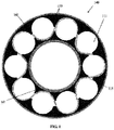
- an example wheel/tire assembly 140 in accordance with the present invention is preferably formed from a lightweight polymer material, such as, for example, a standard tire rubber compound 120 or other polymer.
- the assembly 140 preferably has an extruded cylindrical inner profile 141 and an extruded cylindrical outer profile 142, or spoke structure, which may include a shear band and tread structure.
- the inner and outer profiles 141, 142 together define cavities, preferably cylindrical cavities 111, disposed concentrically about the inner profile 141 allowing the configuration to deflect under load thereby defining a suitable balance between 1) flexibility for ride comfort and traction within a footprint of the assembly 140 and 2) stiffness for vehicle handling, low rolling resistance, and low heat build-up of the assembly 140.
- the cylindrical cavities 111 may further reduce assembly weight while the cylindrical shape of the cavities may maintain essentially homogenous and uniform pressure distribution within the inner and outer profiles 141, 142.
- the dimensions and number of the cylindrical cavities 111 may be varied or made uniform for further tuning of the flexibility/stiffness of the assembly 140.
- the assembly 140 of FIG. 1 preferably further includes a reinforcing membrane 115 interlaced circumferentially and/or radially about the cylindrical cavities 111, preferably circumferentially and radially about the cylindrical cavities 111, for further securing the inner profile 141 to the outer profile 142 and further tuning the flexibility/stiffness of the assembly 140.
- the membrane 115 may be constructed of a metal, polymer, composite, and/or other suitable material for further refining the operating parameters of the assembly 140. The dimensions and number of layers of the membrane 115 may be varied or made uniform for further tuning of the flexibility/stiffness of the assembly 140.
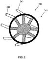
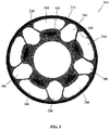
- another example wheel/tire assembly 240 in accordance with the present invention is preferably formed from a lightweight polymer material, such as, for example, a standard tire rubber compound 220 or other polymer.
- the assembly 240 has a preferably cylindrical central hub 241 and a preferably circular outer flexible rim 242, or spoke structure, mounted on the central hub 241 by axially extending projections 243 of the central hub.
- Another ring structure (not shown) preferably secures the outer ends of the projections 243 once the projections are inserted through triangular cavities 244 of the rim 242 thereby securing the central hub 241 to the rim.
- the rim 242 preferably further includes a shear band and tread structure at a radially outer surface of the rim.
- the rim 242 preferably includes triangular cavities 244 and secondary cavities 246 for further reducing weight and distributing stresses throughout the rim.
- the rim 242 may be formed by extrusion, resin transfer molding, injection molding, and/or compression molding of a standard tire compound 220. Fabric reinforcement may also be added to the rim 242 for added strength.
- a tread may be secured to the assembly 240 by adhesive or other suitable method.
Landscapes
- Engineering & Computer Science (AREA)
- Mechanical Engineering (AREA)
- Tires In General (AREA)
Abstract
A wheel and tire assembly for a mobile vehicle is disclosed. The assembly (140, 240) comprises an inner central hub (241); an outer shear band and tread structure mounted on the central hub; and a spoke structure extending between the central hub and the shear band and tread structure, the spoke structure defining a plurality of cavities (111, 244, 246) disposed concentrically about the central hub (241) whereby the cavities (111, 244, 246) allowing the spoke structure to deflect under load.
Description
- The present invention relates to wheel/tire assemblies, and more particularly, to non-pneumatic wheel/tire assemblies, and to a method for non-pneumatically supporting a mobile vehicle.
- Radial pneumatic tires rely on the ply reinforcement to carry and transfer the load between the rim and the belt layer. These ply cords need to be tensioned to carry the load. Tensioning of these ply cords is achieved with the pressurized air in the inner chamber of the tire. If air pressure is lost, load carrying capacity of a pneumatic tire decreases significantly. Preventing the slow or sudden air pressure loss has been a challenge for the tire makers. One proposed solution is to use non-pneumatic tires. A top loader non-pneumatic tire can perform similar to a pneumatic tire if its durability, speed rating/limit and load capacity can be increased to the levels of a pneumatic tire.
- Many top loader non-pneumatic tires rely on the polymeric spokes to carry the load of the vehicle. Spokes transfer the load from the rim to the shear band. Due to the characteristics of the polymeric materials used in the spokes of these tires, performance of these tires are limited. It is an object of the present invention to overcome this limitation and increase the load carrying capacity and durability of these spokes and hence the performance of the top loader non-pneumatic tire.
- The invention relates to an assembly in accordance with claim 1 and to a method in accordance with claim 7.
- Dependent claims refer to preferred embodiments of the invention.
- A wheel and tire assembly in accordance with a preferred aspect of the present invention for a mobile vehicle includes an inner central hub, an outer shear band and tread structure mounted on the central hub, and a spoke structure extending between the central hub and the shear band and tread structure. The spoke structure defines a plurality of cavities disposed concentrically about the central hub whereby the cavities allow the spoke structure to deflect under load.
- In a preferred aspect of the invention, each cavity has a common cross sectional profile about an axis of rotation of the assembly.
- In a preferred aspect of the invention, each cavity has a common axial length equal to a uniform axial thickness of the spoke structure.
- In a preferred aspect of the invention, the assembly comprises a reinforcing membrane interlaced circumferentially and radially about the cavities for further tuning the flexibility and/or stiffness of the spoke structure.
- A method in accordance with a preferred aspect of the present invention non-pneumatically supports a mobile vehicle. The method includes the steps of: rotating a central inner hub about a horizontal axis; mounting the central hub on to an outer ring structure; extending a spoke structure axially and radially between the central hub and the flexible rim; defining a plurality of axially extending cavities in the spoke structure concentrically about the central hub; and vertically loading the spoke structure such that part of the spoke structure deflects vertically.
- In accordance with a preferred aspect of the method, the method includes a further step of interlacing a reinforcing membrane circumferentially and radially about the cavities for further tuning the flexibility/stiffness of the spoke structure.
- According to still another prefererd aspect of the method, further steps tune the flexibility/stiffness of the spoke structure and interlace a reinforcing membrane circumferentially and radially about the cavities.
- According to still another prefererd aspect of the method, a further step buckles a shaft at a predetermined load on the spoke structure.
- The present invention will be more clearly understood by the following description of some examples thereof, with reference to the accompanying drawings, in which:
-
FIG. 1 is a schematic side view of an example assembly in accordance with the present invention; -
FIG. 2 is a schematic perspective view of part of the example assembly ofFIG. 1 ; and -
FIG. 3 is a schematic side view of still another example assembly in accordance with the present invention. - A conventional wheel, such as that described in
US-A-2004/0069385 , may have an outer rim flexibly connected to a central hub by means of lightweight composite springs. The springs may be plates fixed to the rim and to the hub. The hub may contain a speed reduction gear unit and/or an electric motor and may have a suspension mechanism for connecting a vehicle chassis to each wheel. The rim may be constructed from a flexible composite material, such as carbon fiber reinforced nylon material and have twin rubber tires and a plurality of circumferentially spaced-apart radial cleats which engage the ground and provide improved traction. The hub may also be formed from a carbon fiber reinforced composite material. - Another conventional wheel may have a rubber strip with a molded tread bonded to a composite rim for improved grip. Further, the springs interconnecting the rim and hub may be S-shaped lightweight composite springs.
- Still another conventional wheel may have a rim connected to a hub by means of a plurality of S-shaped springs. Each spring may have an inner end attached to the hub and an outer end attached to the rim. A different construction of rubber strip with molded tread may extend about an exterior of the rim.
- Yet another conventional wheel/tire assembly may be formed from a lightweight composite material, such as carbon fiber reinforced polyamide. The assembly may have a cylindrical central hub and a circular outer flexible rim mounted on the central hub by an endless looped spring band extending between the central hub and the circular rim. Six radial loops may be defined by the spring band. The spring band may be attached to the central hub and to the circular rim by any suitable means, such as adhesion, cohesion, soldering and/or mechanical fixing by means of bolts, rivets, and/or clamps. The assembly may further have a limit stop disc mounted on the central hub, coaxial with the central hub, and disposed radially outward from the central hub. An outer peripheral edge of the stop disc may be disposed spaced-apart and radially inward from an inner face of the circular rim for engagement with the circular rim upon radially inward flexing of the circular rim by a preset distance.
- As shown in
FIG. 1 , an example wheel/tire assembly 140 in accordance with the present invention is preferably formed from a lightweight polymer material, such as, for example, a standardtire rubber compound 120 or other polymer. Theassembly 140 preferably has an extruded cylindricalinner profile 141 and an extruded cylindricalouter profile 142, or spoke structure, which may include a shear band and tread structure. - The inner and
outer profiles cylindrical cavities 111, disposed concentrically about theinner profile 141 allowing the configuration to deflect under load thereby defining a suitable balance between 1) flexibility for ride comfort and traction within a footprint of theassembly 140 and 2) stiffness for vehicle handling, low rolling resistance, and low heat build-up of theassembly 140. Thecylindrical cavities 111 may further reduce assembly weight while the cylindrical shape of the cavities may maintain essentially homogenous and uniform pressure distribution within the inner andouter profiles cylindrical cavities 111 may be varied or made uniform for further tuning of the flexibility/stiffness of theassembly 140. - The
assembly 140 ofFIG. 1 preferably further includes areinforcing membrane 115 interlaced circumferentially and/or radially about thecylindrical cavities 111, preferably circumferentially and radially about thecylindrical cavities 111, for further securing theinner profile 141 to theouter profile 142 and further tuning the flexibility/stiffness of theassembly 140. Themembrane 115 may be constructed of a metal, polymer, composite, and/or other suitable material for further refining the operating parameters of theassembly 140. The dimensions and number of layers of themembrane 115 may be varied or made uniform for further tuning of the flexibility/stiffness of theassembly 140. - As shown in
FIGS. 2 and3 , another example wheel/tire assembly 240 in accordance with the present invention is preferably formed from a lightweight polymer material, such as, for example, a standardtire rubber compound 220 or other polymer. Theassembly 240 has a preferably cylindricalcentral hub 241 and a preferably circular outerflexible rim 242, or spoke structure, mounted on thecentral hub 241 by axially extendingprojections 243 of the central hub. Another ring structure (not shown) preferably secures the outer ends of theprojections 243 once the projections are inserted throughtriangular cavities 244 of therim 242 thereby securing thecentral hub 241 to the rim. Therim 242 preferably further includes a shear band and tread structure at a radially outer surface of the rim. - As shown in
FIG. 3 , therim 242 preferably includestriangular cavities 244 andsecondary cavities 246 for further reducing weight and distributing stresses throughout the rim. Therim 242 may be formed by extrusion, resin transfer molding, injection molding, and/or compression molding of astandard tire compound 220. Fabric reinforcement may also be added to therim 242 for added strength. A tread may be secured to theassembly 240 by adhesive or other suitable method.
Claims (12)
- A wheel and tire assembly for a mobile vehicle, the assembly (140, 240) comprising:an inner central hub (241);an outer shear band and tread structure mounted on the central hub; anda spoke structure extending between the central hub and the shear band and tread structure, the spoke structure defining a plurality of cavities (111, 244, 246) disposed concentrically about the central hub (241) whereby the cavities (111, 244, 246) allowing the spoke structure to deflect under load.
- The wheel and tire assembly as set forth in claim 1 wherein the spoke structure comprises a polymer material (120, 220) such as a rubber compound, preferably a homogenous polymer material (120, 220).
- The wheel and tire assembly as set forth in claim 1 or 2 wherein each cavity (111, 244, 246) has a common cross sectional profile about an axis of rotation of the assembly (140, 240).
- The wheel and tire assembly as set forth in at least one of the previous claims wherein each cavity (111, 244, 246) has a common axial length equal to a uniform axial thickness of the spoke structure.
- The wheel and tire assembly as set forth in at least one of the previous claims wherein the assembly (140, 240) further comprises a reinforcing membrane (115) interlaced circumferentially and/or radially about the cavities (111, 244, 246).
- The wheel and tire assembly as set forth in at least one of the previous claims wherein the spoke structure comprises a uniform rubber material (120, 220).
- A method for non-pneumatically supporting a mobile vehicle, the method comprising the steps of:mounting a central inner hub (241) onto an outer ring structure and/or onto a flexible rim;extending a spoke structure axially and radially between the central inner hub (241) and the outer ring structure and/or onto the flexible rim; anddefining and establishing a plurality of axially extending cavities (111, 244, 246) in the spoke structure concentrically about the central hub (241).
- The method of claim 7, further comprising
rotating the central inner hub (241) about a horizontal axis; and
vertically loading the spoke structure such that part of the spoke structure deflects vertically. - The method as set forth in claim 7 or 8 wherein the spoke structure comprises a polymer material, preferably a homogenous polymer material, or a uniform rubber material.
- The method as set forth in at least one of the claims 7 to 9 further including the step of interlacing a reinforcing membrane (115) circumferentially and/or radially about the cavities (111, 244, 246).
- The method as set forth in at least one of the claims 7 to 10 further including the steps of:tuning the flexibility and/or the stiffness of the spoke structure; andinterlacing a reinforcing membrane (115) circumferentially and radially about the cavities (111, 244, 246).
- The method as set forth in at least one of the claims 7 to 11 further including the step of buckling a shaft at a predetermined load on the spoke structure.
Applications Claiming Priority (1)
| Application Number | Priority Date | Filing Date | Title |
|---|---|---|---|
| US15/351,717 US10150334B2 (en) | 2016-11-15 | 2016-11-15 | Non-pneumatic support structure |
Publications (1)
| Publication Number | Publication Date |
|---|---|
| EP3321101A1 true EP3321101A1 (en) | 2018-05-16 |
Family
ID=60244993
Family Applications (1)
| Application Number | Title | Priority Date | Filing Date |
|---|---|---|---|
| EP17199927.9A Withdrawn EP3321101A1 (en) | 2016-11-15 | 2017-11-03 | Non-pneumatic support structure |
Country Status (6)
| Country | Link |
|---|---|
| US (1) | US10150334B2 (en) |
| EP (1) | EP3321101A1 (en) |
| JP (1) | JP2018079924A (en) |
| KR (1) | KR20180054473A (en) |
| CN (1) | CN108068536A (en) |
| BR (1) | BR102017024572A2 (en) |
Families Citing this family (11)
| Publication number | Priority date | Publication date | Assignee | Title |
|---|---|---|---|---|
| US10207544B2 (en) * | 2016-11-15 | 2019-02-19 | The Goodyear Tire & Rubber Company | Wheel for a support structure |
| EP3558695B1 (en) * | 2016-12-22 | 2021-02-03 | Compagnie Générale des Etablissements Michelin | Non-pneumatic wheel and method of mounting non-pneumatic tire |
| US10286725B2 (en) | 2017-03-22 | 2019-05-14 | The Goodyear Tire & Rubber Company | Non-pneumatic support structure |
| KR102211026B1 (en) * | 2019-08-07 | 2021-02-03 | 금호타이어 주식회사 | Non pneumatic tire |
| US11273673B2 (en) | 2019-10-25 | 2022-03-15 | The Goodyear Tire & Rubber Company | Modular non-pneumatic support structure |
| US11142022B2 (en) | 2019-11-15 | 2021-10-12 | The Goodyear Tire & Rubber Company | Support structure |
| US11318791B2 (en) | 2019-11-15 | 2022-05-03 | The Goodyear Tire & Rubber Company | Wheel for a support structure |
| US11124024B2 (en) | 2019-11-25 | 2021-09-21 | The Goodyear Tire & Rubber Company | Support structure |
| EP3871902B1 (en) | 2020-02-28 | 2023-07-19 | The Goodyear Tire & Rubber Company | Non-pneumatic tire |
| KR102392650B1 (en) | 2020-11-03 | 2022-05-02 | 금호타이어 주식회사 | Tire with cooling channel |
| CN113199909A (en) * | 2021-05-31 | 2021-08-03 | 中科院长春应化所黄埔先进材料研究院 | Non-pneumatic tire |
Citations (8)
| Publication number | Priority date | Publication date | Assignee | Title |
|---|---|---|---|---|
| US20040069385A1 (en) | 2002-07-01 | 2004-04-15 | Sean Timoney | Wheel |
| US20100200131A1 (en) * | 2007-07-31 | 2010-08-12 | Toyo Tire & Rubber Co., Ltd. | Non-pneumatic tire and its manufacturing method |
| US20110024008A1 (en) * | 2009-07-28 | 2011-02-03 | Ali Manesh | Tension-based non-pneumatic tire |
| JP2011219009A (en) * | 2010-04-12 | 2011-11-04 | Toyo Tire & Rubber Co Ltd | Non-pneumatic tire, and method of manufacturing the same |
| JP2011246049A (en) * | 2010-05-28 | 2011-12-08 | Toyo Tire & Rubber Co Ltd | Non-pneumatic tire |
| KR20120063616A (en) * | 2010-12-08 | 2012-06-18 | 한국타이어 주식회사 | Non-pneumatic tires |
| KR20130073112A (en) * | 2011-12-23 | 2013-07-03 | 한국타이어 주식회사 | Airless tire |
| US20150174954A1 (en) * | 2013-12-24 | 2015-06-25 | Bridgestone Americas Tire Operations, Llc | Airless tire construction having variable stiffness |
Family Cites Families (21)
| Publication number | Priority date | Publication date | Assignee | Title |
|---|---|---|---|---|
| US482175A (en) | 1892-09-06 | George hollafolla | ||
| US479255A (en) | 1892-07-19 | boyd dunlop | ||
| US1002003A (en) | 1910-07-23 | 1911-08-29 | Christian J Simonson | Steel tire. |
| US1233722A (en) | 1917-01-03 | 1917-07-17 | Frederick Kemppel | Resilient wheel. |
| US1389285A (en) | 1920-03-29 | 1921-08-30 | August W Althoff | Vehicle-wheel |
| US1451517A (en) | 1922-02-27 | 1923-04-10 | William H Smith | Spring wheel |
| US1930764A (en) | 1931-11-05 | 1933-10-17 | Wingfoot Corp | Pneumatic tire and method of making same |
| US3493027A (en) | 1966-05-20 | 1970-02-03 | Nasa | Deformable vehicle wheel |
| US4226273A (en) | 1978-06-30 | 1980-10-07 | The Goodyear Tire & Rubber Company | Nonpneumatic tire and rim assembly |
| US4235270A (en) | 1978-06-30 | 1980-11-25 | The Goodyear Tire & Rubber Company | Tire with supporting and cushioning walls |
| US4602823A (en) | 1981-08-18 | 1986-07-29 | Berg Charles A | Portable collapsible wheels |
| CA2043082A1 (en) | 1991-02-27 | 1992-08-28 | James Edward Duddey | Non-pneumatic spare tire |
| US5800643A (en) | 1996-04-26 | 1998-09-01 | Inner Tire Corporation | Pneumatic inner tire |
| EP0890453B1 (en) | 1997-07-11 | 2004-09-29 | Sumitomo Rubber Industries Limited | Pneumatic tyre |
| US6068721A (en) | 1998-03-27 | 2000-05-30 | The Goodyear Tire & Rubber Company | Method of fabricating a tire having a geodesic ply |
| CN101687432B (en) | 2007-06-29 | 2012-01-25 | 米其林研究和技术股份有限公司 | Elastic shear band with cylindrical elements and wheel including the shearing tape |
| JP4506853B2 (en) * | 2008-02-25 | 2010-07-21 | 横浜ゴム株式会社 | Non-pneumatic tire |
| FR2928865B1 (en) | 2008-03-19 | 2010-03-19 | Michelin Soc Tech | NON-PNEUMATIC ELASTIC WHEEL |
| US9327548B2 (en) * | 2011-09-22 | 2016-05-03 | Kawasaki Jukogyo Kabushiki Kaisha | Wheel for motorcycle |
| BR112016026815A2 (en) * | 2014-05-16 | 2018-11-27 | Michelin & Cie | thermoplastic wheel hub and non-pneumatic tire |
| US10040317B2 (en) * | 2016-11-15 | 2018-08-07 | The Goodyear Tire & Rubber Company | Non-pneumatic support structure |
-
2016
- 2016-11-15 US US15/351,717 patent/US10150334B2/en active Active
-
2017
- 2017-11-03 EP EP17199927.9A patent/EP3321101A1/en not_active Withdrawn
- 2017-11-13 KR KR1020170150265A patent/KR20180054473A/en not_active Ceased
- 2017-11-14 JP JP2017218859A patent/JP2018079924A/en active Pending
- 2017-11-15 CN CN201711128808.8A patent/CN108068536A/en active Pending
- 2017-11-16 BR BR102017024572-1A patent/BR102017024572A2/en not_active IP Right Cessation
Patent Citations (8)
| Publication number | Priority date | Publication date | Assignee | Title |
|---|---|---|---|---|
| US20040069385A1 (en) | 2002-07-01 | 2004-04-15 | Sean Timoney | Wheel |
| US20100200131A1 (en) * | 2007-07-31 | 2010-08-12 | Toyo Tire & Rubber Co., Ltd. | Non-pneumatic tire and its manufacturing method |
| US20110024008A1 (en) * | 2009-07-28 | 2011-02-03 | Ali Manesh | Tension-based non-pneumatic tire |
| JP2011219009A (en) * | 2010-04-12 | 2011-11-04 | Toyo Tire & Rubber Co Ltd | Non-pneumatic tire, and method of manufacturing the same |
| JP2011246049A (en) * | 2010-05-28 | 2011-12-08 | Toyo Tire & Rubber Co Ltd | Non-pneumatic tire |
| KR20120063616A (en) * | 2010-12-08 | 2012-06-18 | 한국타이어 주식회사 | Non-pneumatic tires |
| KR20130073112A (en) * | 2011-12-23 | 2013-07-03 | 한국타이어 주식회사 | Airless tire |
| US20150174954A1 (en) * | 2013-12-24 | 2015-06-25 | Bridgestone Americas Tire Operations, Llc | Airless tire construction having variable stiffness |
Also Published As
| Publication number | Publication date |
|---|---|
| KR20180054473A (en) | 2018-05-24 |
| US10150334B2 (en) | 2018-12-11 |
| BR102017024572A2 (en) | 2018-08-14 |
| CN108068536A (en) | 2018-05-25 |
| US20180134071A1 (en) | 2018-05-17 |
| JP2018079924A (en) | 2018-05-24 |
Similar Documents
| Publication | Publication Date | Title |
|---|---|---|
| US10150334B2 (en) | Non-pneumatic support structure | |
| US10040317B2 (en) | Non-pneumatic support structure | |
| US10207544B2 (en) | Wheel for a support structure | |
| EP3378676B1 (en) | Tire and wheel assembly having a non-pneumatic support structure | |
| US10603956B2 (en) | Wheel for a support structure | |
| EP3599107B1 (en) | Wheel for a support structure | |
| EP3321100A1 (en) | System and method of manufacturing a non-pneumatic support structure | |
| KR101955822B1 (en) | A method of producing a non-pneumatic support structure | |
| KR20220077876A (en) | System for manufacturing a support structure | |
| EP3822092B1 (en) | Wheel assembly for a support structure | |
| EP3812168B1 (en) | Modular non-pneumatic support structure and method | |
| US20210146719A1 (en) | Support structure | |
| US12202219B2 (en) | System for manufacturing a support structure | |
| EP4112286A1 (en) | System and method for manufacturing a support structure | |
| EP4197807B1 (en) | Tire/rim assembly for a support structure |
Legal Events
| Date | Code | Title | Description |
|---|---|---|---|
| PUAI | Public reference made under article 153(3) epc to a published international application that has entered the european phase |
Free format text: ORIGINAL CODE: 0009012 |
|
| AK | Designated contracting states |
Kind code of ref document: A1 Designated state(s): AL AT BE BG CH CY CZ DE DK EE ES FI FR GB GR HR HU IE IS IT LI LT LU LV MC MK MT NL NO PL PT RO RS SE SI SK SM TR |
|
| AX | Request for extension of the european patent |
Extension state: BA ME |
|
| STAA | Information on the status of an ep patent application or granted ep patent |
Free format text: STATUS: THE APPLICATION IS DEEMED TO BE WITHDRAWN |
|
| 18D | Application deemed to be withdrawn |
Effective date: 20181117 |