EP3321066A1 - Single extruder configuration that enables multi-color extrusions in three-dimensional object printers - Google Patents
Single extruder configuration that enables multi-color extrusions in three-dimensional object printers Download PDFInfo
- Publication number
- EP3321066A1 EP3321066A1 EP17201194.2A EP17201194A EP3321066A1 EP 3321066 A1 EP3321066 A1 EP 3321066A1 EP 17201194 A EP17201194 A EP 17201194A EP 3321066 A1 EP3321066 A1 EP 3321066A1
- Authority
- EP
- European Patent Office
- Prior art keywords
- extruder
- nozzles
- thermoplastic material
- faceplate
- nozzle
- Prior art date
- Legal status (The legal status is an assumption and is not a legal conclusion. Google has not performed a legal analysis and makes no representation as to the accuracy of the status listed.)
- Granted
Links
- 238000001125 extrusion Methods 0.000 title description 60
- 239000012815 thermoplastic material Substances 0.000 claims abstract description 90
- 238000000034 method Methods 0.000 claims description 33
- 239000000463 material Substances 0.000 abstract description 112
- 238000004519 manufacturing process Methods 0.000 abstract description 15
- 239000000654 additive Substances 0.000 abstract description 12
- 230000000996 additive effect Effects 0.000 abstract description 12
- 239000003086 colorant Substances 0.000 description 19
- 230000008569 process Effects 0.000 description 17
- 238000007639 printing Methods 0.000 description 11
- 230000015572 biosynthetic process Effects 0.000 description 9
- 239000007787 solid Substances 0.000 description 5
- 238000013500 data storage Methods 0.000 description 4
- 238000010438 heat treatment Methods 0.000 description 4
- 238000010146 3D printing Methods 0.000 description 3
- 229920000122 acrylonitrile butadiene styrene Polymers 0.000 description 3
- 230000000694 effects Effects 0.000 description 3
- 239000007790 solid phase Substances 0.000 description 3
- 239000004372 Polyvinyl alcohol Substances 0.000 description 2
- 238000001816 cooling Methods 0.000 description 2
- 238000010586 diagram Methods 0.000 description 2
- 238000005516 engineering process Methods 0.000 description 2
- 239000012530 fluid Substances 0.000 description 2
- 230000006870 function Effects 0.000 description 2
- 229920005669 high impact polystyrene Polymers 0.000 description 2
- 239000004797 high-impact polystyrene Substances 0.000 description 2
- 238000005304 joining Methods 0.000 description 2
- 239000000155 melt Substances 0.000 description 2
- 229920002451 polyvinyl alcohol Polymers 0.000 description 2
- 229920000049 Carbon (fiber) Polymers 0.000 description 1
- 239000004677 Nylon Substances 0.000 description 1
- 239000004676 acrylonitrile butadiene styrene Substances 0.000 description 1
- 230000004913 activation Effects 0.000 description 1
- 125000001931 aliphatic group Chemical group 0.000 description 1
- 229920003231 aliphatic polyamide Polymers 0.000 description 1
- 230000009286 beneficial effect Effects 0.000 description 1
- 238000004364 calculation method Methods 0.000 description 1
- 239000004917 carbon fiber Substances 0.000 description 1
- 230000015556 catabolic process Effects 0.000 description 1
- 229920001940 conductive polymer Polymers 0.000 description 1
- 230000001276 controlling effect Effects 0.000 description 1
- 238000005520 cutting process Methods 0.000 description 1
- 238000006731 degradation reaction Methods 0.000 description 1
- 238000005553 drilling Methods 0.000 description 1
- 239000011554 ferrofluid Substances 0.000 description 1
- 239000006260 foam Substances 0.000 description 1
- 239000011521 glass Substances 0.000 description 1
- 239000012212 insulator Substances 0.000 description 1
- 239000007788 liquid Substances 0.000 description 1
- 239000006249 magnetic particle Substances 0.000 description 1
- VNWKTOKETHGBQD-UHFFFAOYSA-N methane Chemical compound C VNWKTOKETHGBQD-UHFFFAOYSA-N 0.000 description 1
- 239000000203 mixture Substances 0.000 description 1
- 230000004048 modification Effects 0.000 description 1
- 238000012986 modification Methods 0.000 description 1
- 229920001778 nylon Polymers 0.000 description 1
- 230000003287 optical effect Effects 0.000 description 1
- 239000008188 pellet Substances 0.000 description 1
- 239000012071 phase Substances 0.000 description 1
- 229920003023 plastic Polymers 0.000 description 1
- 239000004033 plastic Substances 0.000 description 1
- 239000004626 polylactic acid Substances 0.000 description 1
- 229920000642 polymer Polymers 0.000 description 1
- 239000000843 powder Substances 0.000 description 1
- 230000001105 regulatory effect Effects 0.000 description 1
- 229920006012 semi-aromatic polyamide Polymers 0.000 description 1
- 238000000926 separation method Methods 0.000 description 1
- 238000007493 shaping process Methods 0.000 description 1
- 229910001220 stainless steel Inorganic materials 0.000 description 1
- 239000010935 stainless steel Substances 0.000 description 1
- 230000001360 synchronised effect Effects 0.000 description 1
- 230000007704 transition Effects 0.000 description 1
- 238000011144 upstream manufacturing Methods 0.000 description 1
Images


Classifications
-
- B—PERFORMING OPERATIONS; TRANSPORTING
- B29—WORKING OF PLASTICS; WORKING OF SUBSTANCES IN A PLASTIC STATE IN GENERAL
- B29C—SHAPING OR JOINING OF PLASTICS; SHAPING OF MATERIAL IN A PLASTIC STATE, NOT OTHERWISE PROVIDED FOR; AFTER-TREATMENT OF THE SHAPED PRODUCTS, e.g. REPAIRING
- B29C48/00—Extrusion moulding, i.e. expressing the moulding material through a die or nozzle which imparts the desired form; Apparatus therefor
- B29C48/03—Extrusion moulding, i.e. expressing the moulding material through a die or nozzle which imparts the desired form; Apparatus therefor characterised by the shape of the extruded material at extrusion
- B29C48/05—Filamentary, e.g. strands
-
- B—PERFORMING OPERATIONS; TRANSPORTING
- B29—WORKING OF PLASTICS; WORKING OF SUBSTANCES IN A PLASTIC STATE IN GENERAL
- B29C—SHAPING OR JOINING OF PLASTICS; SHAPING OF MATERIAL IN A PLASTIC STATE, NOT OTHERWISE PROVIDED FOR; AFTER-TREATMENT OF THE SHAPED PRODUCTS, e.g. REPAIRING
- B29C48/00—Extrusion moulding, i.e. expressing the moulding material through a die or nozzle which imparts the desired form; Apparatus therefor
- B29C48/25—Component parts, details or accessories; Auxiliary operations
- B29C48/30—Extrusion nozzles or dies
- B29C48/345—Extrusion nozzles comprising two or more adjacently arranged ports, for simultaneously extruding multiple strands, e.g. for pelletising
-
- B—PERFORMING OPERATIONS; TRANSPORTING
- B29—WORKING OF PLASTICS; WORKING OF SUBSTANCES IN A PLASTIC STATE IN GENERAL
- B29C—SHAPING OR JOINING OF PLASTICS; SHAPING OF MATERIAL IN A PLASTIC STATE, NOT OTHERWISE PROVIDED FOR; AFTER-TREATMENT OF THE SHAPED PRODUCTS, e.g. REPAIRING
- B29C64/00—Additive manufacturing, i.e. manufacturing of three-dimensional [3D] objects by additive deposition, additive agglomeration or additive layering, e.g. by 3D printing, stereolithography or selective laser sintering
- B29C64/10—Processes of additive manufacturing
- B29C64/106—Processes of additive manufacturing using only liquids or viscous materials, e.g. depositing a continuous bead of viscous material
- B29C64/118—Processes of additive manufacturing using only liquids or viscous materials, e.g. depositing a continuous bead of viscous material using filamentary material being melted, e.g. fused deposition modelling [FDM]
-
- B—PERFORMING OPERATIONS; TRANSPORTING
- B29—WORKING OF PLASTICS; WORKING OF SUBSTANCES IN A PLASTIC STATE IN GENERAL
- B29C—SHAPING OR JOINING OF PLASTICS; SHAPING OF MATERIAL IN A PLASTIC STATE, NOT OTHERWISE PROVIDED FOR; AFTER-TREATMENT OF THE SHAPED PRODUCTS, e.g. REPAIRING
- B29C64/00—Additive manufacturing, i.e. manufacturing of three-dimensional [3D] objects by additive deposition, additive agglomeration or additive layering, e.g. by 3D printing, stereolithography or selective laser sintering
- B29C64/20—Apparatus for additive manufacturing; Details thereof or accessories therefor
- B29C64/205—Means for applying layers
- B29C64/209—Heads; Nozzles
-
- B—PERFORMING OPERATIONS; TRANSPORTING
- B29—WORKING OF PLASTICS; WORKING OF SUBSTANCES IN A PLASTIC STATE IN GENERAL
- B29C—SHAPING OR JOINING OF PLASTICS; SHAPING OF MATERIAL IN A PLASTIC STATE, NOT OTHERWISE PROVIDED FOR; AFTER-TREATMENT OF THE SHAPED PRODUCTS, e.g. REPAIRING
- B29C64/00—Additive manufacturing, i.e. manufacturing of three-dimensional [3D] objects by additive deposition, additive agglomeration or additive layering, e.g. by 3D printing, stereolithography or selective laser sintering
- B29C64/30—Auxiliary operations or equipment
- B29C64/307—Handling of material to be used in additive manufacturing
- B29C64/321—Feeding
- B29C64/336—Feeding of two or more materials
-
- B—PERFORMING OPERATIONS; TRANSPORTING
- B29—WORKING OF PLASTICS; WORKING OF SUBSTANCES IN A PLASTIC STATE IN GENERAL
- B29C—SHAPING OR JOINING OF PLASTICS; SHAPING OF MATERIAL IN A PLASTIC STATE, NOT OTHERWISE PROVIDED FOR; AFTER-TREATMENT OF THE SHAPED PRODUCTS, e.g. REPAIRING
- B29C64/00—Additive manufacturing, i.e. manufacturing of three-dimensional [3D] objects by additive deposition, additive agglomeration or additive layering, e.g. by 3D printing, stereolithography or selective laser sintering
- B29C64/30—Auxiliary operations or equipment
- B29C64/386—Data acquisition or data processing for additive manufacturing
- B29C64/393—Data acquisition or data processing for additive manufacturing for controlling or regulating additive manufacturing processes
-
- B—PERFORMING OPERATIONS; TRANSPORTING
- B33—ADDITIVE MANUFACTURING TECHNOLOGY
- B33Y—ADDITIVE MANUFACTURING, i.e. MANUFACTURING OF THREE-DIMENSIONAL [3-D] OBJECTS BY ADDITIVE DEPOSITION, ADDITIVE AGGLOMERATION OR ADDITIVE LAYERING, e.g. BY 3-D PRINTING, STEREOLITHOGRAPHY OR SELECTIVE LASER SINTERING
- B33Y10/00—Processes of additive manufacturing
-
- B—PERFORMING OPERATIONS; TRANSPORTING
- B33—ADDITIVE MANUFACTURING TECHNOLOGY
- B33Y—ADDITIVE MANUFACTURING, i.e. MANUFACTURING OF THREE-DIMENSIONAL [3-D] OBJECTS BY ADDITIVE DEPOSITION, ADDITIVE AGGLOMERATION OR ADDITIVE LAYERING, e.g. BY 3-D PRINTING, STEREOLITHOGRAPHY OR SELECTIVE LASER SINTERING
- B33Y30/00—Apparatus for additive manufacturing; Details thereof or accessories therefor
-
- B—PERFORMING OPERATIONS; TRANSPORTING
- B33—ADDITIVE MANUFACTURING TECHNOLOGY
- B33Y—ADDITIVE MANUFACTURING, i.e. MANUFACTURING OF THREE-DIMENSIONAL [3-D] OBJECTS BY ADDITIVE DEPOSITION, ADDITIVE AGGLOMERATION OR ADDITIVE LAYERING, e.g. BY 3-D PRINTING, STEREOLITHOGRAPHY OR SELECTIVE LASER SINTERING
- B33Y40/00—Auxiliary operations or equipment, e.g. for material handling
-
- B—PERFORMING OPERATIONS; TRANSPORTING
- B33—ADDITIVE MANUFACTURING TECHNOLOGY
- B33Y—ADDITIVE MANUFACTURING, i.e. MANUFACTURING OF THREE-DIMENSIONAL [3-D] OBJECTS BY ADDITIVE DEPOSITION, ADDITIVE AGGLOMERATION OR ADDITIVE LAYERING, e.g. BY 3-D PRINTING, STEREOLITHOGRAPHY OR SELECTIVE LASER SINTERING
- B33Y50/00—Data acquisition or data processing for additive manufacturing
- B33Y50/02—Data acquisition or data processing for additive manufacturing for controlling or regulating additive manufacturing processes
-
- B—PERFORMING OPERATIONS; TRANSPORTING
- B29—WORKING OF PLASTICS; WORKING OF SUBSTANCES IN A PLASTIC STATE IN GENERAL
- B29K—INDEXING SCHEME ASSOCIATED WITH SUBCLASSES B29B, B29C OR B29D, RELATING TO MOULDING MATERIALS OR TO MATERIALS FOR MOULDS, REINFORCEMENTS, FILLERS OR PREFORMED PARTS, e.g. INSERTS
- B29K2105/00—Condition, form or state of moulded material or of the material to be shaped
- B29K2105/0058—Liquid or visquous
- B29K2105/0067—Melt
Landscapes
- Engineering & Computer Science (AREA)
- Chemical & Material Sciences (AREA)
- Materials Engineering (AREA)
- Manufacturing & Machinery (AREA)
- Mechanical Engineering (AREA)
- Physics & Mathematics (AREA)
- Optics & Photonics (AREA)
- Extrusion Moulding Of Plastics Or The Like (AREA)
Abstract
Description
- This disclosure is directed to extruders used in three-dimensional object printers and, more particularly, to the production of three-dimensional object using multiple extrusions of different colors.
- Three-dimensional printing, also known as additive manufacturing, is a process of making a three-dimensional solid object from a digital model of virtually any shape. Many three-dimensional printing technologies use an additive process in which an additive manufacturing device forms successive layers of the part on top of previously deposited layers. Some of these technologies use extruders that soften or melt extrusion material, such as ABS plastic, into thermoplastic material and then emit the thermoplastic material in a predetermined pattern. The printer typically operates the extruder to form successive layers of the thermoplastic material that form a three-dimensional printed object with a variety of shapes and structures. After each layer of the three-dimensional printed object is formed, the thermoplastic material cools and hardens to bond the layer to an underlying layer of the three-dimensional printed object. This additive manufacturing method is distinguishable from traditional object-forming techniques, which mostly rely on the removal of material from a work piece by a subtractive process, such as cutting or drilling.
- Many extruders are fed extrusion material filaments that are melted or softened to form the thermoplastic material. Even though the filaments are produced in a full range of colors, current extruders in three-dimensional object printers have very limited color capability. Typically, extruded materials of different colors are produced with separate extruders that extrude material of only one color. Because the extruded thermoplastic material possesses high viscosity, the different extruded materials are difficult to mix. Therefore, most printers of this type are limited to two differently colored materials. The differently colored materials from two separate extruders can be used to make a color image in or on an object by printing a base of the object in one color and a pattern in the second color on top of the base. Adding multiple extruders to a printer adds greatly to the complexity of the printer, but only provides a limited color range. Making an outline of an object with extruded thermoplastic materials from multiple extruders invariably leaves breaks in the surface. To avoid these breaks, different colors are alternated from one layer to another.
- Another printer configuration used to produce differently colored extruded materials uses a filament splicer that produces a single multi-color filament from a plurality of differently colored extrusion material filaments by combining them serially lengthwise. The single multi-color filament is fed to a heater that feeds a single extruder. Thus, the thermoplastic material extruded by the extruder changes as the differently colored sections of the filament are melted or softened. The splicer pre-calculates the amount of a thermoplastic material required to form a portion of the object having a particular color and a segment of an extrusion material filament of that color is spliced into the single filament. By continuing to splice an appropriate length of a filament of another color to the single filament, the extruder can continue to produce the object until its formation is complete. This splicer is primarily used to form areas of solid color in the object. The use of the splicer requires precise calculations regarding the lengths of the different filament segments to form the single filament and limits the resolution of the thermoplastic materials extruded by the extruder. Additionally, detecting whether the delivery of the thermoplastic material produced from the multi-colored filament is synchronized with the formation of the appropriate object portions is difficult.
- Providing a three-dimensional object printer with a greater range of colors over known printers and enabling a variety of techniques for forming the object would be beneficial.
- A new extruder uses extrusion materials having a range of different properties and arranges the different extruded materials with more flexibility to form objects. The apparatus includes an extruder having a plurality of manifolds and a plurality of nozzles, each manifold being configured to store thermoplastic material and each manifold being operatively connected to at least one nozzle in the plurality of nozzles through which thermoplastic material from the manifold can be emitted and no two of the manifolds are operatively connected to a same nozzle, and a faceplate having a plurality of apertures, each aperture in the faceplate being configured to receive thermoplastic material extruded from a nozzle in the plurality of nozzles in a one-to-one correspondence to enable the extruded thermoplastic material to pass through the aperture.
- A new method operates an extruder to use extrusion materials having a range of different properties and to arrange the different extruded materials with more flexibility to form objects. The method includes supplying a plurality of thermoplastic materials to a plurality of manifolds in an extruder in a one-to-one correspondence, each manifold being operatively connected to a different nozzle of the extruder and each thermoplastic material having a property that is different than the property of the other thermoplastic materials, and extruding thermoplastic material from the different nozzles of the extruder through a plurality of apertures in a faceplate.
- The foregoing aspects and other features of systems that form objects with thermoplastic material extruded from extruders are explained in the following description, taken in connection with the accompanying drawings.
-
FIG. 1 depicts an additive manufacturing system that enables a greater range of colors for the thermoplastic materials extruded by an extruder and more flexibility in forming objects with the extruded materials. -
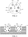
FIG. 2 is a configuration of a faceplate and extruder nozzles that can be used in the system ofFIG. 1 . -
FIG. 3 illustrates an operation of the configuration shown inFIG. 2 to produce color in an object. -
FIG. 4A and 4B depict alternative embodiments of faceplate and extruder nozzle configurations. -
FIG. 5 illustrates the use of the faceplate and extruder nozzle configuration ofFIG. 2 to produce different colors in an object. -
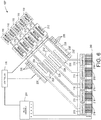
FIG. 6 is a block diagram of an alternative embodiment of the system shown inFIG. 1 that has only one heater with a plurality of channels. -
FIG. 7 is a diagram of a prior art three-dimensional object printer. - For a general understanding of the environment for the device disclosed herein as well as the details for the device, reference is made to the drawings. In the drawings, like reference numerals designate like elements.
- As used herein, the term "extrusion material" refers to a material that is softened or melted to form thermoplastic material to be emitted by an extruder in an additive manufacturing system. The extrusion materials include, but are not strictly limited to, both "build materials" that form permanent portions of the three-dimensional printed object and "support materials" that form temporary structures to support portions of the build material during a printing process and are then optionally removed after completion of the printing process. Examples of build materials include, but are not limited to, acrylonitrile butadiene styrene (ABS) plastic, polylactic acid (PLA), aliphatic or semi-aromatic polyamides (Nylon), plastics that include suspended carbon fiber or other aggregate materials, electrically conductive polymers, and any other form of material that can be thermally treated to produce thermoplastic material suitable for emission through an extruder. Examples of support materials include, but are not limited to, high-impact polystyrene (HIPS), polyvinyl alcohol (PVA), and other materials capable of extrusion after being thermally treated. In some extrusion printers, the extrusion material is supplied as continuous elongated length of material commonly known as a "filament." This filament is provided in a solid form by one or more rollers pulling the extrusion material filament from a spool or other supply and feeding the filament into a heater that is fluidly connected to a manifold within the extruder. The heater softens or melts the extrusion material filament to form a thermoplastic material that flows into the manifold. When a valve positioned between a nozzle and the manifold is opened, a portion of the thermoplastic material flows from the manifold through the nozzle and is emitted as a stream of thermoplastic material. As used herein, the term "melt" as applied to extrusion material refers to any elevation of temperature for the extrusion material that softens or changes the phase of the extrusion material to enable extrusion of the thermoplastic material through one or more nozzles in a extruder during operation of a three-dimensional object printer. The melted extrusion material is also denoted as "thermoplastic material" in this document. As those of skill in the art recognize, certain amorphous extrusion materials do not transition to a pure liquid state during operation of the printer.
- As used herein, the terms "extruder" refers to a component of a printer that melts extrusion material in a single fluid chamber and provides the melted extrusion material to a manifold connected to one or more nozzles. Some extruders include a valve assembly that can be electronically operated to enable thermoplastic material to flow through nozzles selectively. The valve assembly enables the independent connecting of one or more nozzles to the manifold to extrude the thermoplastic material. As used herein, the term "nozzle" refers to an orifice in an extruder that is fluidly connected to the manifold in an extruder and through which thermoplastic material is emitted towards an image receiving surface. During operation, the nozzle can extrude a substantially continuous linear arrangement of the thermoplastic material along the process path of the extruder. A controller operates the valves in the valve assembly to control which nozzles connected to the valve assembly extrude thermoplastic material. The diameter of the nozzle affects the width of the line of extruded thermoplastic material. Different extruder embodiments include nozzles having a range of orifice sizes with wider orifices producing lines having widths that are greater than the widths of lines produced by narrower orifices.
- As used herein, the term "manifold" refers to a cavity formed within a housing of an extruder that holds a supply of thermoplastic material for delivery to one or more nozzles in the extruder during a three-dimensional object printing operation. As used herein, the term "arrangement of extrusion material" refers to any pattern of the extrusion material that the extruder forms on an image receiving surface during a three-dimensional object printing operation. Common arrangements of extrusion material include straight-line linear arrangements of the extrusion material and curved arrangements of the extrusion material. In some configurations, the extruder extrudes the thermoplastic material in a continuous manner to form the arrangement with a contiguous mass of the extrusion material while in other configurations the extruder operates in an intermittent manner to form smaller groups of thermoplastic material that are arranged along a linear or curved path. The three-dimensional object printer forms various structures using combinations of different arrangements of the extrusion material. Additionally, a controller in the three-dimensional object printer uses object image data and extruder path data that correspond to different arrangements of the extrusion material prior to operating the extruder to form each arrangement of the extrusion material. As described below, the controller optionally adjusts the operation of the valve assembly to form multiple arrangements of thermoplastic material through one or more nozzles during a three-dimensional printing operation.
- As used herein, the term "process direction" refers to a direction of relative movement between an extruder and an image receiving surface that receives thermoplastic material extruded from one or more nozzles in the extruder. The image receiving surface is either a support member that holds a three-dimensional printed object or a surface of the partially formed three-dimensional object during an additive manufacturing process. In the illustrative embodiments described herein, one or more actuators move the extruder about the support member, but alternative system embodiments move the support member to produce the relative motion in the process direction while the extruder remains stationary. Some systems use a combination of both systems for different axes of motion.
- As used herein, the term "cross process direction" refers to an axis that is perpendicular to the process direction in the plane of the process direction. The process direction and cross-process direction refer to the relative path of movement of the extruder and the surface that receives the thermoplastic material. In some configurations, the extruder includes an array of nozzles that extend along the cross-process direction. Adjacent nozzles within the extruder are separated by a predetermined distance in the cross-process direction. In some configurations, the system rotates the extruder to adjust the effect cross-process direction distance that separates different nozzles in the extruder to adjust the corresponding cross-process direction distance that separates arrangements of the thermoplastic material that are extruded from the nozzles in the extruder.
- During operation of the additive manufacturing system, an extruder moves in the process direction along both straight and curved paths relative to a surface that receives thermoplastic material during the three-dimensional object printing process. Additionally, an actuator in the system optionally rotates the extruder about the Z axis to adjust the effective cross-process distance that separates nozzles in the extruder to enable the extruder to form two or more arrangements of thermoplastic material with predetermined distances between each arrangement of the thermoplastic material. The extruder moves both along the outer perimeter to form outer walls of a two-dimensional region in a layer of the printed object and within the perimeter to fill all or a portion of the two-dimensional region with the thermoplastic material.
-
FIG. 7 depicts a prior art three-dimensional object additive manufacturing system orprinter 100 that is configured to operate anextruder 108 to form a three-dimensional printedobject 140. Although theprinter 100 is depicted as a printer that uses planar motion to form an object, other printer architectures can be used with the extruder and mechanical mover of extrusion material described in this document. These architectures include delta-bots, selective compliance assembly robot arms (SCARAs), multi-axis printers, non-Cartesian printers, and the like. Theprinter 100 includes asupport member 102, amulti-nozzle extruder 108,extruder support arm 112,controller 128,memory 132, X/Y actuators 150, anoptional Zθ actuator 154, and aZ actuator 158. In theprinter 100, the X/Y actuators 150 move theextruder 108 to different locations in a two-dimensional plane (the "X-Y plane") along the X and Y axes to extrude arrangements of thermoplastic material that form one layer in a three-dimensional printed object, such as theobject 140 that is depicted inFIG. 7 . For example, inFIG. 7 the X/Y actuators 150 translate thesupport arm 112 andextruder 108 alongguide rails 113 to move along the Y axis while the X/Y actuators 150 translate theextruder 108 along the length of thesupport arm 112 to move the extruder along the X axis. The extruded patterns include both outlines of one or more regions in the layer and swaths of the thermoplastic material that fill in the regions within the outline of thermoplastic material patterns. The Z actuator 158 controls the distance between theextruder 108 and thesupport member 102 along the Z axis to ensure that the nozzles in theextruder 108 remain at a suitable height to extrude thermoplastic material onto theobject 140 as the object is formed during the printing process. The Zθ actuator 154 controls an angle of rotation of theextruder 108 about the Z axis (referenced as Zθ inFIG. 4 ) for some embodiments of theextruder 108 that rotate about the Z axis. This movement controls the separation between nozzles in theextruder 108, although some extruders do not require rotation during the manufacturing process. In thesystem 100, the X/Y actuators 150,Zθ actuator 154, and theZ actuator 158 are embodied as electromechanical actuators, such as electric motors, stepper motors, or any other suitable electromechanical device. In the illustrative embodiment ofFIG. 7 , the three-dimensional object printer 100 is depicted during formation of a three-dimensional printedobject 140 that is formed from a plurality of layers of thermoplastic material. - The
support member 102 is a planar member, such as a glass plate, polymer plate, or foam surface, which supports the three-dimensional printedobject 140 during the manufacturing process. In the embodiment ofFIG. 6 , theZ actuator 158 also moves thesupport member 102 in the direction Z away from theextruder 108 after application of each layer of thermoplastic material to ensure that theextruder 108 maintains a predetermined distance from the upper surface of theobject 140. Theextruder 108 includes a plurality of nozzles and each nozzle extrudes thermoplastic material onto the surface of thesupport member 102 or a surface of a partially formed object, such theobject 140. In the example ofFIG. 7 , extrusion material is provided as a filament fromextrusion material supply 110, which is a spool of ABS plastic or another suitable extrusion material filament that unwraps from the spool to supply extrusion material to theextruder 108. - The
support arm 112 includes a support member and one or more actuators that move theextruder 108 during printing operations. In thesystem 100, one ormore actuators 150 move thesupport arm 112 andextruder 108 along the X and Y axes during the printing operation. For example, one of theactuators 150 moves thesupport arm 112 and theextruder 108 along the Y axis while another actuator moves theextruder 108 along the length of thesupport arm 112 to move along the X axis. In thesystem 100, the X/Y actuators 150 optionally move theextruder 108 along both the X and Y axes simultaneously along either straight or curved paths. Thecontroller 128 controls the movements of theextruder 108 in both linear and curved paths that enable the nozzles in theextruder 108 to extrude thermoplastic material onto thesupport member 102 or onto previously formed layers of theobject 140. Thecontroller 128 optionally moves theextruder 108 in a rasterized motion along the X axis or Y axis, but the X/Y actuators 150 can also move theextruder 108 along arbitrary linear or curved paths in the X-Y plane. - The
controller 128 is a digital logic device such as a microprocessor, microcontroller, field programmable gate array (FPGA), application specific integrated circuit (ASIC) or any other digital logic that is configured to operate theprinter 100. In theprinter 100, thecontroller 128 is operatively connected to one or more actuators that control the movement of thesupport member 102 and thesupport arm 112. Thecontroller 128 is also operatively connected to amemory 132. In the embodiment of theprinter 100, thememory 132 includes volatile data storage devices, such as random access memory (RAM) devices, and non-volatile data storage devices such as solid-state data storage devices, magnetic disks, optical disks, or any other suitable data storage devices. Thememory 132 stores programmedinstruction data 134 and three-dimensional (3D) objectimage data 136. Thecontroller 128 executes the storedprogram instructions 134 to operate the components in theprinter 100 to form the three-dimensional printedobject 140 and print two-dimensional images on one or more surfaces of theobject 140. The 3Dobject image data 136 includes, for example, a plurality of two-dimensional image data patterns that correspond to each layer of thermoplastic material that theprinter 100 forms during the three-dimensional object printing process. The extruder path controldata 138 include a set of geometric data or actuator control commands that thecontroller 128 processes to control the path of movement of theextruder 108 using the X/Y actuators 150 and to control the orientation of theextruder 108 using theZθ actuator 154. Thecontroller 128 operates the actuators to move theextruder 108 above thesupport member 102 as noted above while the extruder extrudes thermoplastic material to form an object. -
FIG. 1 depicts an additive manufacturing system 100' having anextruder 108 that extrudes a plurality of thermoplastic materials through apertures in a faceplate as shown inFIG. 2 , which is described in more detail below. Although only onemanifold 216 is shown inFIG. 1 to simplify the figure, theextruder 108 has a plurality ofmanifolds 216. In one embodiment, each manifold 216 in theextruder 108 is operatively connected to adifferent heater 208 that is fed by a differentextrusion material supply 110 in a one-to-one correspondence. Alternatively, each manifold 216 can be coupled to a single heater 208' that houses a plurality of channels 232' that are fed by a plurality of extrusion material supplies 110 as shown in theembodiment 100" ofFIG. 6 . Each channel 232' inFIG. 6 supplies thermoplastic material to a manifold 216 in theextruder 108 to enable each manifold to receive a material that is different than a material that the other manifolds are receiving. In theextruder 108, eachnozzle 218 is fluidly connected to only one of the manifolds within theextruder 108 so each nozzle can extrude a thermoplastic material that is different than the materials extruded from nozzles connected to other manifolds. Extrusion from each nozzle is selectively and independently activated and deactivated bycontroller 128 operating the valves in thevalve assembly 204. Eachnozzle 218 is also aligned with an aperture in afaceplate 260, as described in more detail below, to configure the nozzles for more flexible formation of arrangements of the materials in an object. The configuration ofFIG. 6 corresponds with an embodiment of the faceplate similar to the one shown inFIG. 4B , but which provides three nozzles for each of the five manifolds rather than three nozzles for six manifolds as depicted inFIG. 4B . - In the embodiments of
FIG. 1 andFIG. 6 , avalve assembly 204 positions a valve between the manifolds in theextruder 108 and each of the nozzles connected to the manifolds in theextruder 108. Thevalve assembly 204 is operatively connected to thecontroller 128 so the controller can open and close the valves for extruding thermoplastic material from the plurality of nozzles in theextruder 108. Specifically, thecontroller 128 activates and deactivates different actuators in theassembly 204 connected to the valves in theextruder 108 to extrude thermoplastic material from the nozzles and form arrangements of different thermoplastic materials in each layer of the three-dimensional printedobject 140. - The system 100' of
FIG. 1 also includes an extrusionmaterial dispensing system 212 for eachheater 208 that is connected to a manifold in theextruder 108. The extrusion material from eachseparate supply 110 is fed to thecorresponding heater 208 at a rate that maintains the pressure of the thermoplastic material in the manifold connected to the heater within a predetermined range during operation of the system 100'. Thedispensing system 212 is one embodiment that is suitable for regulating pressure of the thermoplastic material in each manifold of theextruder 108. Inembodiment 100" ofFIG. 6 , a plurality of extrusionmaterial dispensing systems 212 are operatively connected between a plurality of extrusion material supplies 110 and a channel 232' in the heater 208' in a one-to-one correspondence. Additionally, in both embodiments, thecontroller 128 is operatively connected to an actuator each dispensingsystem 212 to control the rate at which thedispensing system 212 delivers extrusion material from asupply 110 to the heater fed by the supply. The dispensingsystems 212 ofFIG. 6 can be configured as thedispensing system 212 ofFIG. 1 . Theheaters 208 and 208' soften or melt theextrusion material 220 fed to theheater 208 via drive roller 224 (FIG. 1 ).Actuator 240 drives theroller 224 and is operatively connected to thecontroller 128 so the controller can regulate the speed at which the actuator drives theroller 224. Another roller oppositeroller 224 is free-wheeling so it follows the rate of rotation at whichroller 224 is driven. WhileFIG. 1 depicts a feed system that uses an electromechanical actuator and thedriver roller 224 as a mechanical mover to move thefilament 220 into theheater 208 or 208', alternative embodiments of thedispensing system 212 use one or more actuators to operate a mechanical mover in the form of a rotating auger or screw. The auger or screw moves solid phase extrusion material from asupply 110 in the form of extrusion material powder or pellets into aheater 208 or 208'. - In the embodiments of
FIG. 1 andFIG. 6 , each heater is formed from stainless steel and includes one ormore heating elements 228, such as electrically resistive heating elements, which are operatively connected to thecontroller 128.Controller 128 is configured to connect theheating elements 228 to electrical current selectively to soften or melt the filament ofextrusion material 220 in the channel or channels within theheater 208 or 208'. WhileFIG. 1 andFIG. 6 show heater 208 and heater 208' receiving extrusion material in a solid phase assolid filament 220, in alternative embodiments, the heaters receive the extrusion material in solid phase as powdered or pelletized extrusion material. Coolingfins 236 attenuate heat in the channels upstream from the heater. A portion of the extrusion material that remains solid in a channel at or near the coolingfins 236 forms a seal in the channel that prevents thermoplastic material from exiting the heater from any other opening than the connection to themanifold 216. Theextruder 108 can also include additional heating elements to maintain an elevated temperature for the thermoplastic material within each manifold within the extruder. In some embodiments, a thermal insulator covers portions of the exterior of theextruder 108 to maintain a temperature within the manifolds within the extruder. The reader should appreciate that the length of the nozzles inFIG. 6 is as short as those depicted inFIG. 1 so the thermoplastic material does not begin solidifying during its travel to the apertures in the faceplate. - To maintain a fluid pressure of the thermoplastic material within the
manifolds 216 within a predetermined range, avoid damage to the extrusion material, and control the extrusion rate through the nozzles, aslip clutch 244 is operatively connected to the drive shaft of each actuator 240 that feeds filament from asupply 110 to a heater. As used in this document, the term "slip clutch" refers to a device applies frictional force to an object to move the object up to a predetermined set point. When the range about the predetermined set point for the frictional force is exceeded, the device slips so it no longer applies the frictional force to the object. The slip clutch enables the force exerted on thefilament 220 to remain constant no matter how frequently or how long a valve within theassembly 204 is opened or how fast the actuator 240 drivesroller 224. This constant force can be maintained by either driving theactuator 240 at a speed that is higher than the fastest expected rotational speed of thefilament drive roller 224 or by putting anencoder wheel 248 on theroller 224 and sensing the rate of rotation with asensor 252. The signal generated by thesensor 252 indicates the angular rotation of theroller 224 and thecontroller 128 receives this signal to identify the speed of theroller 224. Thecontroller 128 is further configured to adjust the signal provided to theactuator 240 to control the speed of the actuator. When the controller is configured to control the speed of theactuator 240, thecontroller 128 operates theactuator 240 so its speed is slightly faster than the rotation of theroller 224. This operation ensures that the torque on thedrive roller 224 is always a function of the slip clutch torque. - The
controller 128 has a set point stored in memory connected to the controller that identifies the slightly higher speed of the actuator output shaft over the rotational speed of theroller 224. As used in this document, the term "set point" means a parameter value that a controller uses to operate components to keep the parameter corresponding to the set point within a predetermined range about the set point. For example, thecontroller 128 changes a signal that operates theactuator 240 to rotate the output shaft at a speed identified by the output signal in a predetermined range about the set point. In addition to the commanded speed for the actuator, the number of valves opened or closed in thevalve assembly 204 and the torque set point for the clutch also affect thefilament drive system 212 operation. The resulting rotational speed of theroller 224 is identified by the signal generated by thesensor 252. A proportional-integral-derivative (PID) controller withincontroller 128 identifies an error from this signal with reference to the differential set point stored in memory and adjusts the signal output by the controller to operate theactuator 240. Alternatively, thecontroller 128 can alter the torque level for the slip clutch or thecontroller 128 can both alter the torque level and adjust the signal with which the controller operates the actuator. - The
slip clutch 244 can be a fixed or adjustable torque friction disc clutch, a magnetic particle clutch, a magnetic hysteresis clutch, a ferro-fluid clutch, an air pressure clutch, or permanent magnetic clutch. The clutch types that operate magnetically can have their torque set points adjusted by applying a voltage to the clutches. This feature enables the torque set point on the clutch to be changed with reference to print conditions. The term "print conditions" refers to parameters of the currently ongoing manufacturing operation that affect the amount of thermoplastic material required in the manifold for adequate formation of the object. These print conditions include the type of extrusion material being fed to the extruder, the temperature of the thermoplastic material being emitted from the extruder, the speed at which the extruder is being moved in the X-Y plane, the position of the feature being formed on the object, and the like. -
FIG. 2 shows afaceplate 260 and a configuration of six nozzles 264a, 264b, 264c, 264d, 264e, and 264f, which are aligned with sixapertures 268 in the faceplate. As used in this document, the term "faceplate" refers to a single planar member having a plurality of apertures that enable thermoplastic material to be extruded from the nozzles of a plurality of extruders. Use of a single faceplate for a plurality of nozzles in an extruder enables different materials to be printed simultaneously so they join together while at the elevated temperatures. This joining of the different materials helps prevent weak spots in the object being formed; however, the joining of the different materials does not mean the materials mix with one another. Thus, the order and placement of the different materials substantially affects the layers and surfaces of the object. - In the discussion below, the different extrusion materials supplied to a plurality of
heaters 208 or a single heater 208' have different colors. The selective formation of arrangements within layers enables the object to be formed with different colors and shades of colors at the surfaces and edges of the object. The reader should understand that the different extrusion materials can have different properties other than color. For example, the different property can be hardness of the material to enable the object to be formed with varying degrees of hardness in different portions of the object. In the discussion below, however, color is the property that is being used to describe the operation of the various embodiments and how they produce variations in portions of an object. As used in this document, the term "property" refers to a characteristic of an extrusion material that can differ for each extrusion material used in an additive manufacturing system. - At an object edge, the color of the material extruded toward the outside of the edge predominates, while at a top surface, the extruded materials can be positioned adjacent one another or over one of the other materials to determine color. When one nozzle is aligned with another nozzle in a direction of travel for the faceplate, the later extruded material lays on the earlier extruded material so it tends to dominate the color appearance of the top surface. For example, in
FIG. 2 , nozzles 264a and 264b are aligned when the faceplate travels left to right or right to left. Therefore, when the faceplate travels to the right, the color of the material from nozzle 264a tends to dominate the appearance of the top surface, and when the faceplate travels to the left, the color of the material from nozzle 264b tends to dominate. By manipulating the flow of thermoplastic materials from the nozzles and rotating the faceplate to orient the nozzles differently, the color perceived at the visible portions of the object can be controlled. Where color cannot be perceived, such as the interior of an object, all of the nozzles can operated to form the arrangements for an object and maximize the printing speed. - In
FIG. 2 , for example, nozzle 264a emits cyan colored material, nozzle 264b emits magenta colored material, nozzle 264d emits yellow colored material, and nozzle 264f emits black colored material. White is also useful for varying colors so nozzle 264e extrudes white colored material, while nozzle 264c extrudes red colored material. This selection of colors is exemplary only as the filaments feeding theheaters 208 for the various manifolds in theextruders 108 can be any known filament color.FIG. 3 illustrates the use of the configuration ofFIG. 2 being operated to form a green edge of arectangular object 304. The "X"s in the nozzles 264b, 264d, 264e, and 264f indicate the valves feeding those nozzles have been closed. Thus, only cyan material from nozzle 264a and yellow material from nozzle 264c are extruded. Regardless of the direction in which thefaceplate 260 is moved, either right to left or left to right, thefaceplate 260 is rotated about an axis perpendicular to thefaceplate 260 betweenorientation 1 andorientation 2 as shown in the figure. Inorientation 1, cyan dominates, while inorientation 2, yellow dominates. By alternating between the two orientations, an edge is formed that a human observer perceives as being green. The amount of time that one orientation is used versus the other orientation determines the shade of green that an observer perceives. The reader should also note that the nozzles 264b, 264d, 264e, and 264f can remain open without compromising the color of the edge since the nozzles extruding the cyan and yellow materials remain at the outside of the object provided the cyan and yellow materials are relative opaque. If the cyan and yellow materials are relatively highly translucent, then white material may be required to avoid degradation of the color being formed. Formation of corners may require the closing of the nozzles not extruding cyan or yellow materials prior to or while the faceplate is turning through a corner, but, in some cases, the use of these nozzles can be useful for gradually shaping curves. - While the example discussed with reference to
FIG. 3 uses only two colors, any number of colors and orientations can be used to form colors at an edge or surface of an object. Also, lighter or darker shades of a color can be produced by including white or black extruded materials, respectively. The rate at which ejectors are alternated and the selective activation of the nozzles that extrude material at a surface of the object determine how finely the variations between colors can be detailed and how accurately desired color changes can be produced at the edges and surfaces of objects. - Alternative embodiments of the
faceplate 260 and other configurations of the plurality of extruders are shown inFIG. 4A and 4B . In these embodiments, each color of thermoplastic material provided by the nozzles infaceplate 260 ofFIG. 2 is extruded through a plurality of nozzles. For example, each of the cyan, magenta, yellow, black, white, and red colored materials are provided through two nozzles in the faceplate 260' ofFIG. 4A , while each of those colors of materials are provided through three nozzles in thefaceplate 260" ofFIG. 4B . Each of the nozzles extruding the same color are connected to the same manifold in theextruder 108 and a different valve in theassembly 204 is positioned between that manifold and each nozzle. Thus, thecontroller 128 can operate thevalve assembly 204 to open or close all of the nozzles or only selected nozzles for a particular color. Additionally, each of the nozzles for a single color can have the same diameter or different diameters. Thus, the embodiments ofFIG. 4A and 4B enhance the flexibility and resolution of the arrangements of extruded thermoplastic materials through the faceplates of these embodiments. Moreover, if the nozzles are arranged in the faceplates so the different colors overlap uniformly, each of the nozzles for a single color can be sequenced by independently operating the valves for the nozzles to produce an effect similar to the one discussed above with reference toFIG. 3 . Additionally, the operation of the valves can be combined with different rotations of the faceplate to add further flexibility to the formation of colors for the object. - The
orientations FIG. 3 can be used as shown inFIG. 5 to produce different color effects on a surface of the object as viewed from a perspective looking down on the surface of the object. On the left side of the figure,orientation 1 produces cyan thermoplastic material that is adjacent to yellow thermoplastic material regardless of which direction the faceplate is moved. Similarly, iforientation 2 was used, the two materials are reversed, but are still adjacent to one another regardless of faceplate movement direction. On the right, an orientation is shown that aligns the nozzle 264a with nozzle 264c. When the faceplate moves to the right as indicated by the arrow in the upper right depiction, the cyan thermoplastic material covers the yellow thermoplastic material, but if the same orientation is move to the left as indicated by the arrow in the lower right depiction, the yellow material covers the cyan material. Thus, color formation for an object can be affected by rotating the faceplate, controlling the valves between the manifolds and the nozzles, and moving the faceplate in a particular direction. - It will be appreciated that variants of the above-disclosed and other features and functions, or alternatives thereof, may be desirably combined into many other different systems, applications or methods. Various presently unforeseen or unanticipated alternatives, modifications, variations or improvements may be subsequently made by those skilled in the art that are also intended to be encompassed by the following claims.
Claims (10)
- An apparatus comprising:an extruder having a plurality of manifolds and a plurality of nozzles, each manifold being configured to store thermoplastic material and each manifold being operatively connected to at least one nozzle in the plurality of nozzles through which thermoplastic material from the manifold can be emitted and no two of the manifolds are operatively connected to a same nozzle; anda faceplate having a plurality of apertures, each aperture in the faceplate being configured to receive thermoplastic material extruded from a nozzle in the plurality of nozzles in a one-to-one correspondence to enable the extruded thermoplastic material to pass through the aperture.
- The apparatus of claim 1 further comprising:a plurality of valves, each valve being operatively connected between a nozzle in the plurality of nozzles and the manifold to which the nozzle is operatively connected in the extruder, each valve being configured to open and close the nozzle selectively; anda controller configured to operate each valve to extrude thermoplastic material from each nozzle selectively.
- The apparatus of claim 2 wherein at least one manifold is operatively connected to at least two nozzles.
- The apparatus of claim 1, the extruder and the faceplate being configured to move relative to an object in more than one direction.
- The apparatus of claim 4 wherein the faceplate and the plurality of nozzles are configured for rotation about an axis perpendicular to the faceplate.
- A method comprising:supplying a plurality of thermoplastic materials to a plurality of manifolds in an extruder in a one-to-one correspondence, each manifold being operatively connected to a different nozzle of the extruder and each thermoplastic material having a property that is different than the property of the other thermoplastic materials; andextruding thermoplastic material from the different nozzles of the extruder through a plurality of apertures in a faceplate.
- The method of claim 6 further comprising:operating with a controller a plurality of valves, each valve being operatively connected between one of the nozzles and the manifold to which the nozzle is operatively connected in the extruder, the controller operating the valves to open and close the nozzles selectively.
- The method of claim 7 further comprising:operating with the controller at least one actuator to move the extruder and the faceplate in more than one direction.
- The method of claim 8 further comprising:operating with the controller the at least one actuator to rotate the faceplate and the plurality of extruders about an axis perpendicular to the faceplate.
- The method of claim 9 further comprising:operating with the controller the plurality of valves to extrude thermoplastic material from at least one of the manifolds through a plurality of nozzles operatively connected to the manifold.
Applications Claiming Priority (1)
| Application Number | Priority Date | Filing Date | Title |
|---|---|---|---|
| US15/350,200 US10596798B2 (en) | 2016-11-14 | 2016-11-14 | Single extruder configuration that enables multi-color extrusions in three-dimensional object printers |
Publications (2)
| Publication Number | Publication Date |
|---|---|
| EP3321066A1 true EP3321066A1 (en) | 2018-05-16 |
| EP3321066B1 EP3321066B1 (en) | 2020-07-01 |
Family
ID=60301941
Family Applications (1)
| Application Number | Title | Priority Date | Filing Date |
|---|---|---|---|
| EP17201194.2A Active EP3321066B1 (en) | 2016-11-14 | 2017-11-10 | Single extruder configuration that enables multi-color extrusions in three-dimensional object printers |
Country Status (5)
| Country | Link |
|---|---|
| US (2) | US10596798B2 (en) |
| EP (1) | EP3321066B1 (en) |
| JP (1) | JP6891092B2 (en) |
| KR (1) | KR102245599B1 (en) |
| CN (1) | CN108068330B (en) |
Cited By (3)
| Publication number | Priority date | Publication date | Assignee | Title |
|---|---|---|---|---|
| EP3486068A1 (en) * | 2017-11-20 | 2019-05-22 | Xerox Corporation | System for adjusting the speed of a multi-nozzle extruder during additive manufacturing with reference to an angular orientation of the extruder |
| WO2020046267A1 (en) * | 2018-08-27 | 2020-03-05 | Hewlett-Packard Development Company, L.P. | Modules of three-dimensional (3d) printers |
| DE102020105362A1 (en) | 2020-02-28 | 2021-09-02 | Hans Weber Maschinenfabrik Gmbh | Extrusion device for extrusion-based production of at least one three-dimensional object |
Families Citing this family (9)
| Publication number | Priority date | Publication date | Assignee | Title |
|---|---|---|---|---|
| WO2019017869A1 (en) * | 2017-07-17 | 2019-01-24 | Hewlett-Packard Development Company, L.P. | Disguising color in 3d object formation |
| US11000997B2 (en) * | 2018-07-23 | 2021-05-11 | Xerox Corporation | System and method for preserving valve member travel in a multi-nozzle extruder |
| US10894358B2 (en) | 2018-09-13 | 2021-01-19 | Xerox Corporation | Optimized nozzle arrangement for an extruder head used in an additive manufacturing system |
| KR101992625B1 (en) * | 2018-10-30 | 2019-06-25 | 주식회사 티앤알바이오팹 | Multiple nozzle 3D printing system and three-dimensional bio-printing method using the same |
| US10780635B1 (en) * | 2019-10-08 | 2020-09-22 | Thermwood Corporation | Apparatus and method for thermal compensation during additive manufacturing |
| JP7434892B2 (en) * | 2019-12-26 | 2024-02-21 | 富士フイルムビジネスイノベーション株式会社 | modeling equipment |
| JP2021151751A (en) * | 2020-03-24 | 2021-09-30 | 富士フイルムビジネスイノベーション株式会社 | Modeling device |
| CN113320167A (en) * | 2021-05-27 | 2021-08-31 | 武汉科技大学 | Preparation method of full-color 3D printing supplies |
| CN113799391B (en) * | 2021-09-15 | 2023-04-18 | 泉州信息工程学院 | 3D printer multicolor wire feeding device and working method thereof |
Citations (4)
| Publication number | Priority date | Publication date | Assignee | Title |
|---|---|---|---|---|
| US20140034214A1 (en) * | 2012-07-31 | 2014-02-06 | Makerbot Industries, Llc | Build material switching |
| DE202014004344U1 (en) * | 2014-05-21 | 2014-07-08 | Cem Schnitzler | Crown extruder |
| US20160129644A1 (en) * | 2014-11-11 | 2016-05-12 | Mimaki Engineering Co., Ltd. | Apparatus for modeling three-dimensional object and method for modeling three-dimensional object |
| US20160325498A1 (en) * | 2015-05-04 | 2016-11-10 | Daniel Gelbart | 3D Printer Based on a Staggered Nozzle Array |
Family Cites Families (10)
| Publication number | Priority date | Publication date | Assignee | Title |
|---|---|---|---|---|
| JP5232252B2 (en) * | 2008-03-14 | 2013-07-10 | エーリコン テクスティル ゲゼルシャフト ミット ベシュレンクテル ハフツング ウント コンパニー コマンディートゲゼルシャフト | Equipment for melt spinning multicomponent fibers |
| EP2772347B1 (en) * | 2013-02-27 | 2018-03-28 | CEL Technology Limited | Printer head assembly for a 3D printer |
| US20140363532A1 (en) | 2013-06-10 | 2014-12-11 | Kirk W. Wolfgram | Multiple color extrusion type three dimensional printer |
| US9669586B2 (en) | 2013-10-01 | 2017-06-06 | Autodesk, Inc. | Material dispensing system |
| TW201522019A (en) * | 2013-12-13 | 2015-06-16 | Xyzprinting Inc | Three-dimensional printing apparatus and printing head module |
| US8827684B1 (en) | 2013-12-23 | 2014-09-09 | Radiant Fabrication | 3D printer and printhead unit with multiple filaments |
| CN106660265A (en) * | 2014-06-26 | 2017-05-10 | 株式会社理光 | Three-dimensional shaping method and three-dimensional shaping device method |
| AU2015301229A1 (en) * | 2014-08-04 | 2017-02-16 | Vac-Tron Equipment, Llc | Method and system to manufacture native soil flowable fill |
| CN105128343A (en) * | 2015-10-14 | 2015-12-09 | 湖南华曙高科技有限责任公司 | Preparing method and device for multicolor three-dimensional object |
| US10335991B2 (en) * | 2015-12-08 | 2019-07-02 | Xerox Corporation | System and method for operation of multi-nozzle extrusion printheads in three-dimensional object printers |
-
2016
- 2016-11-14 US US15/350,200 patent/US10596798B2/en active Active
-
2017
- 2017-10-20 JP JP2017203151A patent/JP6891092B2/en active Active
- 2017-10-30 CN CN201711036493.4A patent/CN108068330B/en active Active
- 2017-10-31 KR KR1020170143354A patent/KR102245599B1/en active IP Right Grant
- 2017-11-10 EP EP17201194.2A patent/EP3321066B1/en active Active
-
2020
- 2020-03-03 US US16/807,756 patent/US11207813B2/en active Active
Patent Citations (4)
| Publication number | Priority date | Publication date | Assignee | Title |
|---|---|---|---|---|
| US20140034214A1 (en) * | 2012-07-31 | 2014-02-06 | Makerbot Industries, Llc | Build material switching |
| DE202014004344U1 (en) * | 2014-05-21 | 2014-07-08 | Cem Schnitzler | Crown extruder |
| US20160129644A1 (en) * | 2014-11-11 | 2016-05-12 | Mimaki Engineering Co., Ltd. | Apparatus for modeling three-dimensional object and method for modeling three-dimensional object |
| US20160325498A1 (en) * | 2015-05-04 | 2016-11-10 | Daniel Gelbart | 3D Printer Based on a Staggered Nozzle Array |
Cited By (4)
| Publication number | Priority date | Publication date | Assignee | Title |
|---|---|---|---|---|
| EP3486068A1 (en) * | 2017-11-20 | 2019-05-22 | Xerox Corporation | System for adjusting the speed of a multi-nozzle extruder during additive manufacturing with reference to an angular orientation of the extruder |
| US10682816B2 (en) | 2017-11-20 | 2020-06-16 | Xerox Corporation | System and method for adjusting the speed of a multi-nozzle extruder during additive manufacturing with reference to an angular orientation of the extruder |
| WO2020046267A1 (en) * | 2018-08-27 | 2020-03-05 | Hewlett-Packard Development Company, L.P. | Modules of three-dimensional (3d) printers |
| DE102020105362A1 (en) | 2020-02-28 | 2021-09-02 | Hans Weber Maschinenfabrik Gmbh | Extrusion device for extrusion-based production of at least one three-dimensional object |
Also Published As
| Publication number | Publication date |
|---|---|
| KR20180054438A (en) | 2018-05-24 |
| KR102245599B1 (en) | 2021-04-27 |
| US20180133980A1 (en) | 2018-05-17 |
| CN108068330B (en) | 2022-07-01 |
| US10596798B2 (en) | 2020-03-24 |
| US11207813B2 (en) | 2021-12-28 |
| EP3321066B1 (en) | 2020-07-01 |
| CN108068330A (en) | 2018-05-25 |
| JP2018079688A (en) | 2018-05-24 |
| US20200198317A1 (en) | 2020-06-25 |
| JP6891092B2 (en) | 2021-06-18 |
Similar Documents
| Publication | Publication Date | Title |
|---|---|---|
| US11207813B2 (en) | Single extruder configuration that enables multi-color extrusions in three-dimensional object printers | |
| EP3486068B1 (en) | System for adjusting the speed of a multi-nozzle extruder during additive manufacturing with reference to an angular orientation of the extruder | |
| US10906224B2 (en) | Method for operating a constant pressure filament driver to an extruder head in a three-dimensional object printer | |
| US11104118B2 (en) | System for operating extruder heads in three-dimensional object printers | |
| US11884011B2 (en) | System and method for providing three-dimensional object structural support with a multi-nozzle extruder | |
| EP3715093B1 (en) | Method for operating an extruder in a three-dimensional (3d) object printer to improve layer formation ane three-diemensional (3d) object printer | |
| EP3575060B1 (en) | Method for operating a multi-nozzle extruder using zig-zag patterns that provide improved structual integrity | |
| EP3922438B1 (en) | System and method for operating a multi-nozzle extruder during additive manufacturing | |
| EP3882004A1 (en) | System and method for operating a multi-nozzle extruder during additive manufacturing |
Legal Events
| Date | Code | Title | Description |
|---|---|---|---|
| PUAI | Public reference made under article 153(3) epc to a published international application that has entered the european phase |
Free format text: ORIGINAL CODE: 0009012 |
|
| STAA | Information on the status of an ep patent application or granted ep patent |
Free format text: STATUS: THE APPLICATION HAS BEEN PUBLISHED |
|
| AK | Designated contracting states |
Kind code of ref document: A1 Designated state(s): AL AT BE BG CH CY CZ DE DK EE ES FI FR GB GR HR HU IE IS IT LI LT LU LV MC MK MT NL NO PL PT RO RS SE SI SK SM TR |
|
| AX | Request for extension of the european patent |
Extension state: BA ME |
|
| STAA | Information on the status of an ep patent application or granted ep patent |
Free format text: STATUS: REQUEST FOR EXAMINATION WAS MADE |
|
| 17P | Request for examination filed |
Effective date: 20181116 |
|
| RBV | Designated contracting states (corrected) |
Designated state(s): AL AT BE BG CH CY CZ DE DK EE ES FI FR GB GR HR HU IE IS IT LI LT LU LV MC MK MT NL NO PL PT RO RS SE SI SK SM TR |
|
| GRAP | Despatch of communication of intention to grant a patent |
Free format text: ORIGINAL CODE: EPIDOSNIGR1 |
|
| STAA | Information on the status of an ep patent application or granted ep patent |
Free format text: STATUS: GRANT OF PATENT IS INTENDED |
|
| RIC1 | Information provided on ipc code assigned before grant |
Ipc: B29C 64/106 20170101ALI20200110BHEP Ipc: B33Y 30/00 20150101ALI20200110BHEP Ipc: B29C 64/118 20170101ALI20200110BHEP Ipc: B29C 64/209 20170101AFI20200110BHEP Ipc: B29C 64/20 20170101ALI20200110BHEP |
|
| INTG | Intention to grant announced |
Effective date: 20200129 |
|
| GRAS | Grant fee paid |
Free format text: ORIGINAL CODE: EPIDOSNIGR3 |
|
| GRAA | (expected) grant |
Free format text: ORIGINAL CODE: 0009210 |
|
| STAA | Information on the status of an ep patent application or granted ep patent |
Free format text: STATUS: THE PATENT HAS BEEN GRANTED |
|
| AK | Designated contracting states |
Kind code of ref document: B1 Designated state(s): AL AT BE BG CH CY CZ DE DK EE ES FI FR GB GR HR HU IE IS IT LI LT LU LV MC MK MT NL NO PL PT RO RS SE SI SK SM TR |
|
| REG | Reference to a national code |
Ref country code: CH Ref legal event code: EP Ref country code: AT Ref legal event code: REF Ref document number: 1285762 Country of ref document: AT Kind code of ref document: T Effective date: 20200715 |
|
| REG | Reference to a national code |
Ref country code: IE Ref legal event code: FG4D |
|
| REG | Reference to a national code |
Ref country code: DE Ref legal event code: R096 Ref document number: 602017018945 Country of ref document: DE |
|
| REG | Reference to a national code |
Ref country code: LT Ref legal event code: MG4D |
|
| PG25 | Lapsed in a contracting state [announced via postgrant information from national office to epo] |
Ref country code: BG Free format text: LAPSE BECAUSE OF FAILURE TO SUBMIT A TRANSLATION OF THE DESCRIPTION OR TO PAY THE FEE WITHIN THE PRESCRIBED TIME-LIMIT Effective date: 20201001 |
|
| REG | Reference to a national code |
Ref country code: NL Ref legal event code: MP Effective date: 20200701 |
|
| REG | Reference to a national code |
Ref country code: AT Ref legal event code: MK05 Ref document number: 1285762 Country of ref document: AT Kind code of ref document: T Effective date: 20200701 |
|
| PG25 | Lapsed in a contracting state [announced via postgrant information from national office to epo] |
Ref country code: AT Free format text: LAPSE BECAUSE OF FAILURE TO SUBMIT A TRANSLATION OF THE DESCRIPTION OR TO PAY THE FEE WITHIN THE PRESCRIBED TIME-LIMIT Effective date: 20200701 Ref country code: SE Free format text: LAPSE BECAUSE OF FAILURE TO SUBMIT A TRANSLATION OF THE DESCRIPTION OR TO PAY THE FEE WITHIN THE PRESCRIBED TIME-LIMIT Effective date: 20200701 Ref country code: GR Free format text: LAPSE BECAUSE OF FAILURE TO SUBMIT A TRANSLATION OF THE DESCRIPTION OR TO PAY THE FEE WITHIN THE PRESCRIBED TIME-LIMIT Effective date: 20201002 Ref country code: NO Free format text: LAPSE BECAUSE OF FAILURE TO SUBMIT A TRANSLATION OF THE DESCRIPTION OR TO PAY THE FEE WITHIN THE PRESCRIBED TIME-LIMIT Effective date: 20201001 Ref country code: FI Free format text: LAPSE BECAUSE OF FAILURE TO SUBMIT A TRANSLATION OF THE DESCRIPTION OR TO PAY THE FEE WITHIN THE PRESCRIBED TIME-LIMIT Effective date: 20200701 Ref country code: HR Free format text: LAPSE BECAUSE OF FAILURE TO SUBMIT A TRANSLATION OF THE DESCRIPTION OR TO PAY THE FEE WITHIN THE PRESCRIBED TIME-LIMIT Effective date: 20200701 Ref country code: CZ Free format text: LAPSE BECAUSE OF FAILURE TO SUBMIT A TRANSLATION OF THE DESCRIPTION OR TO PAY THE FEE WITHIN THE PRESCRIBED TIME-LIMIT Effective date: 20200701 Ref country code: PT Free format text: LAPSE BECAUSE OF FAILURE TO SUBMIT A TRANSLATION OF THE DESCRIPTION OR TO PAY THE FEE WITHIN THE PRESCRIBED TIME-LIMIT Effective date: 20201102 Ref country code: LT Free format text: LAPSE BECAUSE OF FAILURE TO SUBMIT A TRANSLATION OF THE DESCRIPTION OR TO PAY THE FEE WITHIN THE PRESCRIBED TIME-LIMIT Effective date: 20200701 Ref country code: ES Free format text: LAPSE BECAUSE OF FAILURE TO SUBMIT A TRANSLATION OF THE DESCRIPTION OR TO PAY THE FEE WITHIN THE PRESCRIBED TIME-LIMIT Effective date: 20200701 |
|
| PG25 | Lapsed in a contracting state [announced via postgrant information from national office to epo] |
Ref country code: LV Free format text: LAPSE BECAUSE OF FAILURE TO SUBMIT A TRANSLATION OF THE DESCRIPTION OR TO PAY THE FEE WITHIN THE PRESCRIBED TIME-LIMIT Effective date: 20200701 Ref country code: PL Free format text: LAPSE BECAUSE OF FAILURE TO SUBMIT A TRANSLATION OF THE DESCRIPTION OR TO PAY THE FEE WITHIN THE PRESCRIBED TIME-LIMIT Effective date: 20200701 Ref country code: RS Free format text: LAPSE BECAUSE OF FAILURE TO SUBMIT A TRANSLATION OF THE DESCRIPTION OR TO PAY THE FEE WITHIN THE PRESCRIBED TIME-LIMIT Effective date: 20200701 Ref country code: IS Free format text: LAPSE BECAUSE OF FAILURE TO SUBMIT A TRANSLATION OF THE DESCRIPTION OR TO PAY THE FEE WITHIN THE PRESCRIBED TIME-LIMIT Effective date: 20201101 |
|
| PG25 | Lapsed in a contracting state [announced via postgrant information from national office to epo] |
Ref country code: NL Free format text: LAPSE BECAUSE OF FAILURE TO SUBMIT A TRANSLATION OF THE DESCRIPTION OR TO PAY THE FEE WITHIN THE PRESCRIBED TIME-LIMIT Effective date: 20200701 |
|
| REG | Reference to a national code |
Ref country code: DE Ref legal event code: R097 Ref document number: 602017018945 Country of ref document: DE |
|
| PG25 | Lapsed in a contracting state [announced via postgrant information from national office to epo] |
Ref country code: SM Free format text: LAPSE BECAUSE OF FAILURE TO SUBMIT A TRANSLATION OF THE DESCRIPTION OR TO PAY THE FEE WITHIN THE PRESCRIBED TIME-LIMIT Effective date: 20200701 Ref country code: IT Free format text: LAPSE BECAUSE OF FAILURE TO SUBMIT A TRANSLATION OF THE DESCRIPTION OR TO PAY THE FEE WITHIN THE PRESCRIBED TIME-LIMIT Effective date: 20200701 Ref country code: EE Free format text: LAPSE BECAUSE OF FAILURE TO SUBMIT A TRANSLATION OF THE DESCRIPTION OR TO PAY THE FEE WITHIN THE PRESCRIBED TIME-LIMIT Effective date: 20200701 Ref country code: RO Free format text: LAPSE BECAUSE OF FAILURE TO SUBMIT A TRANSLATION OF THE DESCRIPTION OR TO PAY THE FEE WITHIN THE PRESCRIBED TIME-LIMIT Effective date: 20200701 Ref country code: DK Free format text: LAPSE BECAUSE OF FAILURE TO SUBMIT A TRANSLATION OF THE DESCRIPTION OR TO PAY THE FEE WITHIN THE PRESCRIBED TIME-LIMIT Effective date: 20200701 |
|
| PLBE | No opposition filed within time limit |
Free format text: ORIGINAL CODE: 0009261 |
|
| STAA | Information on the status of an ep patent application or granted ep patent |
Free format text: STATUS: NO OPPOSITION FILED WITHIN TIME LIMIT |
|
| PG25 | Lapsed in a contracting state [announced via postgrant information from national office to epo] |
Ref country code: AL Free format text: LAPSE BECAUSE OF FAILURE TO SUBMIT A TRANSLATION OF THE DESCRIPTION OR TO PAY THE FEE WITHIN THE PRESCRIBED TIME-LIMIT Effective date: 20200701 |
|
| 26N | No opposition filed |
Effective date: 20210406 |
|
| PG25 | Lapsed in a contracting state [announced via postgrant information from national office to epo] |
Ref country code: MC Free format text: LAPSE BECAUSE OF FAILURE TO SUBMIT A TRANSLATION OF THE DESCRIPTION OR TO PAY THE FEE WITHIN THE PRESCRIBED TIME-LIMIT Effective date: 20200701 Ref country code: SK Free format text: LAPSE BECAUSE OF FAILURE TO SUBMIT A TRANSLATION OF THE DESCRIPTION OR TO PAY THE FEE WITHIN THE PRESCRIBED TIME-LIMIT Effective date: 20200701 |
|
| REG | Reference to a national code |
Ref country code: CH Ref legal event code: PL |
|
| PG25 | Lapsed in a contracting state [announced via postgrant information from national office to epo] |
Ref country code: LU Free format text: LAPSE BECAUSE OF NON-PAYMENT OF DUE FEES Effective date: 20201110 |
|
| REG | Reference to a national code |
Ref country code: BE Ref legal event code: MM Effective date: 20201130 |
|
| PG25 | Lapsed in a contracting state [announced via postgrant information from national office to epo] |
Ref country code: SI Free format text: LAPSE BECAUSE OF FAILURE TO SUBMIT A TRANSLATION OF THE DESCRIPTION OR TO PAY THE FEE WITHIN THE PRESCRIBED TIME-LIMIT Effective date: 20200701 Ref country code: LI Free format text: LAPSE BECAUSE OF NON-PAYMENT OF DUE FEES Effective date: 20201130 Ref country code: CH Free format text: LAPSE BECAUSE OF NON-PAYMENT OF DUE FEES Effective date: 20201130 |
|
| PG25 | Lapsed in a contracting state [announced via postgrant information from national office to epo] |
Ref country code: IE Free format text: LAPSE BECAUSE OF NON-PAYMENT OF DUE FEES Effective date: 20201110 |
|
| PG25 | Lapsed in a contracting state [announced via postgrant information from national office to epo] |
Ref country code: TR Free format text: LAPSE BECAUSE OF FAILURE TO SUBMIT A TRANSLATION OF THE DESCRIPTION OR TO PAY THE FEE WITHIN THE PRESCRIBED TIME-LIMIT Effective date: 20200701 Ref country code: MT Free format text: LAPSE BECAUSE OF FAILURE TO SUBMIT A TRANSLATION OF THE DESCRIPTION OR TO PAY THE FEE WITHIN THE PRESCRIBED TIME-LIMIT Effective date: 20200701 Ref country code: CY Free format text: LAPSE BECAUSE OF FAILURE TO SUBMIT A TRANSLATION OF THE DESCRIPTION OR TO PAY THE FEE WITHIN THE PRESCRIBED TIME-LIMIT Effective date: 20200701 |
|
| PG25 | Lapsed in a contracting state [announced via postgrant information from national office to epo] |
Ref country code: MK Free format text: LAPSE BECAUSE OF FAILURE TO SUBMIT A TRANSLATION OF THE DESCRIPTION OR TO PAY THE FEE WITHIN THE PRESCRIBED TIME-LIMIT Effective date: 20200701 |
|
| PG25 | Lapsed in a contracting state [announced via postgrant information from national office to epo] |
Ref country code: BE Free format text: LAPSE BECAUSE OF NON-PAYMENT OF DUE FEES Effective date: 20201130 |
|
| PGFP | Annual fee paid to national office [announced via postgrant information from national office to epo] |
Ref country code: GB Payment date: 20231019 Year of fee payment: 7 |
|
| PGFP | Annual fee paid to national office [announced via postgrant information from national office to epo] |
Ref country code: FR Payment date: 20231019 Year of fee payment: 7 Ref country code: DE Payment date: 20231019 Year of fee payment: 7 |