EP3321038B1 - Gas spring fastener driver - Google Patents
Gas spring fastener driver Download PDFInfo
- Publication number
- EP3321038B1 EP3321038B1 EP17200840.1A EP17200840A EP3321038B1 EP 3321038 B1 EP3321038 B1 EP 3321038B1 EP 17200840 A EP17200840 A EP 17200840A EP 3321038 B1 EP3321038 B1 EP 3321038B1
- Authority
- EP
- European Patent Office
- Prior art keywords
- nosepiece
- magazine
- battery
- fastener
- driver
- Prior art date
- Legal status (The legal status is an assumption and is not a legal conclusion. Google has not performed a legal analysis and makes no representation as to the accuracy of the status listed.)
- Active
Links
- 230000000903 blocking effect Effects 0.000 claims description 25
- 238000000034 method Methods 0.000 claims description 14
- 230000007246 mechanism Effects 0.000 claims description 6
- 238000003780 insertion Methods 0.000 claims description 5
- 230000037431 insertion Effects 0.000 claims description 5
- 230000004913 activation Effects 0.000 claims description 4
- 230000002401 inhibitory effect Effects 0.000 claims description 2
- 230000000977 initiatory effect Effects 0.000 claims description 2
- 238000004891 communication Methods 0.000 description 2
- 239000000463 material Substances 0.000 description 2
- 229910052751 metal Inorganic materials 0.000 description 2
- 239000002184 metal Substances 0.000 description 2
- FYYHWMGAXLPEAU-UHFFFAOYSA-N Magnesium Chemical compound [Mg] FYYHWMGAXLPEAU-UHFFFAOYSA-N 0.000 description 1
- 238000010276 construction Methods 0.000 description 1
- 238000010304 firing Methods 0.000 description 1
- 239000012530 fluid Substances 0.000 description 1
- 229910052749 magnesium Inorganic materials 0.000 description 1
- 239000011777 magnesium Substances 0.000 description 1
- 230000000717 retained effect Effects 0.000 description 1
Images
Classifications
-
- B—PERFORMING OPERATIONS; TRANSPORTING
- B25—HAND TOOLS; PORTABLE POWER-DRIVEN TOOLS; MANIPULATORS
- B25C—HAND-HELD NAILING OR STAPLING TOOLS; MANUALLY OPERATED PORTABLE STAPLING TOOLS
- B25C1/00—Hand-held nailing tools; Nail feeding devices
- B25C1/04—Hand-held nailing tools; Nail feeding devices operated by fluid pressure, e.g. by air pressure
- B25C1/047—Mechanical details
-
- B—PERFORMING OPERATIONS; TRANSPORTING
- B25—HAND TOOLS; PORTABLE POWER-DRIVEN TOOLS; MANIPULATORS
- B25C—HAND-HELD NAILING OR STAPLING TOOLS; MANUALLY OPERATED PORTABLE STAPLING TOOLS
- B25C1/00—Hand-held nailing tools; Nail feeding devices
- B25C1/04—Hand-held nailing tools; Nail feeding devices operated by fluid pressure, e.g. by air pressure
- B25C1/041—Hand-held nailing tools; Nail feeding devices operated by fluid pressure, e.g. by air pressure with fixed main cylinder
-
- B—PERFORMING OPERATIONS; TRANSPORTING
- B25—HAND TOOLS; PORTABLE POWER-DRIVEN TOOLS; MANIPULATORS
- B25C—HAND-HELD NAILING OR STAPLING TOOLS; MANUALLY OPERATED PORTABLE STAPLING TOOLS
- B25C1/00—Hand-held nailing tools; Nail feeding devices
- B25C1/008—Safety devices
-
- B—PERFORMING OPERATIONS; TRANSPORTING
- B25—HAND TOOLS; PORTABLE POWER-DRIVEN TOOLS; MANIPULATORS
- B25C—HAND-HELD NAILING OR STAPLING TOOLS; MANUALLY OPERATED PORTABLE STAPLING TOOLS
- B25C1/00—Hand-held nailing tools; Nail feeding devices
- B25C1/06—Hand-held nailing tools; Nail feeding devices operated by electric power
-
- B—PERFORMING OPERATIONS; TRANSPORTING
- B25—HAND TOOLS; PORTABLE POWER-DRIVEN TOOLS; MANIPULATORS
- B25C—HAND-HELD NAILING OR STAPLING TOOLS; MANUALLY OPERATED PORTABLE STAPLING TOOLS
- B25C5/00—Manually operated portable stapling tools; Hand-held power-operated stapling tools; Staple feeding devices therefor
- B25C5/10—Driving means
- B25C5/13—Driving means operated by fluid pressure
-
- Y—GENERAL TAGGING OF NEW TECHNOLOGICAL DEVELOPMENTS; GENERAL TAGGING OF CROSS-SECTIONAL TECHNOLOGIES SPANNING OVER SEVERAL SECTIONS OF THE IPC; TECHNICAL SUBJECTS COVERED BY FORMER USPC CROSS-REFERENCE ART COLLECTIONS [XRACs] AND DIGESTS
- Y02—TECHNOLOGIES OR APPLICATIONS FOR MITIGATION OR ADAPTATION AGAINST CLIMATE CHANGE
- Y02E—REDUCTION OF GREENHOUSE GAS [GHG] EMISSIONS, RELATED TO ENERGY GENERATION, TRANSMISSION OR DISTRIBUTION
- Y02E60/00—Enabling technologies; Technologies with a potential or indirect contribution to GHG emissions mitigation
- Y02E60/10—Energy storage using batteries
Definitions
- the present invention relates to power tools, and more particularly to gas spring fastener drivers.
- fastener drivers used to drive fasteners (e.g., nails, tacks, staples, etc.) into a workpiece known in the art.
- fastener drivers operate utilizing various means (e.g., compressed air generated by an air compressor, electrical energy, flywheel mechanisms) known in the art, but often these designs are met with power, size, and cost constraints.
- JP2005001065 relates to a fastener driver according to the preamble of claim 1 .
- a driving-in machine including a cover of a magazine, which, when opened, an engaging arm 52b comes off a terminal plate 63, and the terminal plate 63 is spaced from a contact 60a of the battery 60 to intercept current flowing to the battery 60.
- the charging of the driven members can thereby be performed in a state of inhibiting unprepared driving-in operation without performing special operation.
- a fastener driver including a housing, a cylinder disposed within the housing, a piston positioned and movable within the cylinder, a driver blade attached to the piston and movable with the piston, a motor for driving movement of the piston, a battery removably coupled to the housing for supplying power to the motor, a nosepiece at least partially defining a fastener driving track through which fasteners are driven by the driver blade, and a magazine operable to supply the fasteners to the nosepiece.
- the magazine is removable from the nosepiece only in response to prior removal of the battery from the housing.
- the magazine includes a blocking member engageable with the battery to prevent removal of the magazine from the nosepiece when the battery is coupled to the main housing.
- the nosepiece may be a front nosepiece and the fastener driver may further comprise a rear nosepiece attached to the magazine.
- the fastener driving track may be defined between the front nosepiece and the rear nosepiece.
- the fastener driver may further comprise a quick-release latch that is operable to secure the front nosepiece and the rear nosepiece together.
- the rear nosepiece may include two hooks, respectively, positioned on opposite sides of the fastener driving track.
- the quick-release latch may be engaged with the hooks to secure the front nosepiece and the rear nosepiece together.
- the front nosepiece may define respective apertures through which the hooks extend.
- the quick-release latch may include a lever and a spring pivotably coupled to the lever.
- the lever may be pivotably coupled to the front nosepiece.
- the quick-release latch may further include spaced pins positioned on a lower end of the spring and engageable with the hooks, respectively, for securing the front nosepiece and the rear nosepiece together.
- the magazine may include a blocking member located between a driving axis coaxial with the driver blade and the battery.
- the blocking member may laterally protrude from a side of the magazine closest to the battery.
- the blocking member and the battery may define a first axial gap in a direction parallel with an insertion axis of the battery when the battery is coupled to the housing to supply power to the motor.
- the blocking member may be engageable with the battery, which may thereby prevent further movement of the magazine in the direction parallel with the insertion axis, when the quick-release latch is disengaged from the hooks.
- the rear nosepiece may be separable from the front nosepiece by a second axial gap equal to the first axial gap when the blocking member is engaged with the battery.
- the hooks may be at least partially positioned within the respective apertures in the front nosepiece when the rear nosepiece is separated from the front nosepiece by the second axial gap.
- the rear nosepiece and the magazine may be removably coupled to the front nosepiece as a unit.
- the fastener driver may further comprise an electrical switch operable to detect when the rear nosepiece is removed from the front nosepiece. Activation of the motor may be inhibited in response to the electrical switch detecting removal of the rear nosepiece from the front nosepiece.
- the electrical switch may be coupled to the front nosepiece.
- the rear nosepiece may include a projection engageable with the electrical switch when the rear nosepiece is coupled to the front nosepiece. The projection may disengage the electrical switch in response to removal of the rear nosepiece from the front nosepiece.
- a fastener driver may include a cylinder, a piston positioned and moveable within the cylinder, a driver blade attached to the piston and moveable with the piston, a front nosepiece at least partially defining a fastener driving track through which fasteners are driven by the driver blade, a rear nosepiece at least partially defining the fastener driving track, and a magazine attached to the rear nosepiece and operable to supply the fasteners to the fastener driver track through the rear nosepiece.
- the rear nosepiece and the magazine are removably coupled to the front nosepiece as a unit.
- the fastener driver may further comprise an electrical switch operable to detect when the rear nosepiece is removed from the front nosepiece.
- the fastener driver may further comprise a motor for driving movement of the piston. Activation of the motor may be inhibited in response to the electrical switch detecting removal of the rear nosepiece from the front nosepiece.
- the electrical switch may be coupled to the front nosepiece.
- the rear nosepiece may include a projection engageable with the electrical switch when the rear nosepiece is coupled to the front nosepiece. The projection may disengage the electrical switch in response to removal of the rear nosepiece from the front nosepiece.
- the present invention provides, in yet another aspect, a method of operating a fastener driver according to the previous aspect of the invention.
- the method includes initiating a fastener driving operation by moving the driver blade, with a gas spring mechanism, from a retracted position toward a driven position, stopping the driver blade at an intermediate position between the retracted position and the driven position in response to a fastener jammed in the fastener driving track, detaching the battery from the fastener driver, and removing the magazine from the nosepiece, after the battery has been removed.
- the method may further comprise actuating a switch in response to removal of the magazine from the nosepiece, which may thereby inhibit further operation of the fastener driver.
- the method may further comprise: removing the jammed fastener in the fastener driving track; and reattaching the magazine to the nosepiece.
- the method may still further comprise actuating the switch in response to reattachment of the magazine to the nosepiece, which may thereby return the fastener driver to an operational state.
- the method may further comprise reattaching the battery to the fastener driver after reattachment of the magazine to the nosepiece.
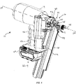
- a gas spring fastener driver 10 for driving fasteners 12 (e.g., nails, tacks, staples, etc.) into a workpiece is shown.
- the fastener driver 10 includes a housing 14, a nosepiece 16 extending from the main housing 14, and a magazine 18 for sequentially feeding fasteners 12 (e.g., collated fasteners) into the nosepiece 16 prior to each fastener-driving operation.
- the magazine 18 of the illustrated embodiment is composed of a magnesium material, in other embodiments, the magazine 18 can alternatively be composed of a different metal or metal allow, or other suitable materials.
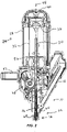
- the fastener driver 10 also includes a drive blade 20 and an onboard gas spring mechanism 24 for driving the drive blade 20 coinciding with ejection of a fastener 12 from the nosepiece 16. Accordingly, the fastener driver 10 does not require an external source of air pressure for driving the drive blade 20. Rather, the gas spring mechanism 24 includes a storage chamber 28 of pressurized gas in fluid communication with a cylinder 32. The cylinder 32 and a moveable piston 36 are positioned within the storage chamber 28.
- the cylinder 32 and the drive blade 20 define a driving axis 44, and during a driving cycle the drive blade 20 and the piston 36 are moveable along the driving axis 44 between a ready position (i.e., top dead center; see FIG. 2 ) and a driven position (i.e., bottom dead center).
- a ready position i.e., top dead center; see FIG. 2
- a driven position i.e., bottom dead center
- the fastener driver 10 further includes a lifting assembly 48, which is powered by a motor 52, and which is operable to move the drive blade 20 from the driven position to the ready position.
- the drive blade 20 is biased to the driven position by compressed gas in the storage chamber 28.
- the fastener driver 10 further includes a handle 56 that is grasped by an operator for maneuvering the fastener driver 10.
- the handle 56 and the motor 52 are both oriented substantially perpendicular to the driving axis 44.
- the fastener driver 10 includes a battery 60 that is removably coupled to the handle 56 along a battery insertion/removal axis 62 that is also perpendicular to the driving axis 44.
- the battery 60 is electrically connectable to the motor 52 for supplying electrical power to the motor 52 to drive the lifting assembly 48.
- the lifting assembly 48 raises the piston 36 and the drive blade 20 from the driven position and toward the ready position by energizing the motor 52.
- the gas above the piston 36 and the gas within the storage chamber 28 is compressed.
- the piston 36 and the drive blade 20 are held in position until released by user activation of a trigger (not shown).
- the compressed gas above the piston 36 and within the storage chamber 28 drives the piston 36 and the drive blade 20 to the driven position, thereby driving a fastener into a workpiece.
- the illustrated fastener driver 10 therefore operates on a gas spring principle utilizing the lifting assembly 48 and the piston 36 to further compress the gas within the cylinder 32 and the storage chamber 28. Further detail regarding the structure and operation of the fastener driver 10 is provided below.
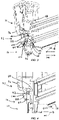
- the nosepiece 16 further includes a front nosepiece 64, a rear nosepiece 68, and an over-center spring latch 72 (i.e., a quick-release latch) operable to secure the rear nosepiece 68 to the front nosepiece 64.
- an over-center spring latch 72 i.e., a quick-release latch operable to secure the rear nosepiece 68 to the front nosepiece 64.
- attaching the rear nosepiece 68 to the front nosepiece 64 also attaches the magazine 18 to the front nosepiece 64.
- a fastener driving track or channel 76 is formed therebetween ( FIG. 3 ).
- the fastener driving track 76 is coaxial with the driving axis 44 and is in communication with the magazine 18 in order to sequentially receive the fasteners 12 from the magazine 18 for consecutive fastener driving operations.
- the rear nosepiece 68 includes a first pair of projections 80 and a second pair of hooks or projections 84, both of which extend away from the rear nosepiece 68 toward the front nosepiece 64, positioned on opposite sides of the fastener driving track 76.
- the first pair of projections 80 extend into corresponding slots 88 defined in the front nosepiece 64.
- an electrical switch 92 e.g., a microswitch, FIG.
- each of the slots 88 may contain a switch 92 to detect when the rear nosepiece 68 is connected to and removed from the front nosepiece 64.
- the spring latch 72 includes a lever 96 pivotably coupled to the front nosepiece 64 and a spring member 100, including spaced pins 103, that is pivotably coupled to the lever 96 in an over-center-type configuration.
- the spring member 100 is engageable (via pins 103) with the second pair of projections 84, which are configured as hooks, that extend through respective apertures 102 in the front nosepiece 64.
- the spring member 100 exerts a clamping force against the projections 84, preventing them from being removed from the apertures 102.
- the rear nosepiece 68 and the magazine 18 are retained to the front nosepiece 64 in an engaged position, as shown in FIG. 3 .
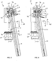
- the spring member 100 releases the clamping force on the projections 84, permitting the spring member 100 to be pivoted away from the front nosepiece 64, and permitting the rear nosepiece 68 (with the attached magazine 18) to be moved in a rearward direction (i.e., toward a disengaged position shown in FIG. 4 ).
- the rear nosepiece 68 and magazine 18 move along a first (i.e., rearward) direction 104 when moving toward the disengaged position and along a second (i.e., forward) direction 108 when moving toward the engaged position.
- the magazine 18 includes a blocking member 112 laterally protruding from a side thereof closest to the housing 14 and battery 60.
- the blocking member 112 is located between the driving axis 44, which is coaxial with the drive blade 20, and the battery 60 ( FIG. 1 ). As shown in FIGS. 5 and 6 , the blocking member 112 protrudes from the magazine 18 by a sufficient amount to overlap a portion of the battery 60.
- the blocking member 112 acts as a safety mechanism because an operator is required to remove the battery 60 (thereby disconnecting any power to the motor 52) prior to removing the magazine 18 for clearing a jammed fastener 12 from the nosepiece 16. By removing the battery 60, any inadvertent fastening operations are avoided.
- the blocking member 112 interferes with a shoulder 116 ( FIG. 6 ) of the battery 60 if removal of the magazine 18 from the nosepiece 16 is attempted prior to removing the battery 60. In the engaged position of the rear nosepiece 68 and magazine 18, a gap 120 exists between the shoulder 116 of the battery 60 and the blocking member 112 ( FIG. 5 ).
- the rear nosepiece 68 and magazine 18 may be moved in direction 104 until the blocking member 112 abuts the shoulder 116, thereby limiting any further movement of the magazine 18 in direction 104 so long as the battery 60 remains attached to the housing 14.
- the gap 120 now exists between the front nosepiece 64 and the rear nosepiece 68.
- the projections 84 remain within the apertures 102 ( FIG. 3 ), preventing the magazine 18 from being removed as long as the battery 60 remains attached to the housing 14.
- the fastener driver 10 will remain deactivated, despite reattachment of the battery 60, until the rear nosepiece 68 and magazine 18 are reattached to the front nosepiece 64.
- the projection 80 contacts and closes the switch 92 (if it is normally open), thereby returning the fastener driver 10 to an active or operational state in which a fastener firing operation may be initiated.
Description
- This application claims priority to co-pending
U.S. Provisional Patent Application No. 62/419,719 filed on November 9, 2016 - The present invention relates to power tools, and more particularly to gas spring fastener drivers.
- There are various fastener drivers used to drive fasteners (e.g., nails, tacks, staples, etc.) into a workpiece known in the art. These fastener drivers operate utilizing various means (e.g., compressed air generated by an air compressor, electrical energy, flywheel mechanisms) known in the art, but often these designs are met with power, size, and cost constraints.
-
JP2005001065 battery 60 to intercept current flowing to thebattery 60. The charging of the driven members can thereby be performed in a state of inhibiting unprepared driving-in operation without performing special operation. - The present invention provides, in one aspect, a fastener driver including a housing, a cylinder disposed within the housing, a piston positioned and movable within the cylinder, a driver blade attached to the piston and movable with the piston, a motor for driving movement of the piston, a battery removably coupled to the housing for supplying power to the motor, a nosepiece at least partially defining a fastener driving track through which fasteners are driven by the driver blade, and a magazine operable to supply the fasteners to the nosepiece. The magazine is removable from the nosepiece only in response to prior removal of the battery from the housing.
- The magazine includes a blocking member engageable with the battery to prevent removal of the magazine from the nosepiece when the battery is coupled to the main housing.
- The nosepiece may be a front nosepiece and the fastener driver may further comprise a rear nosepiece attached to the magazine. The fastener driving track may be defined between the front nosepiece and the rear nosepiece.
- The fastener driver may further comprise a quick-release latch that is operable to secure the front nosepiece and the rear nosepiece together. The rear nosepiece may include two hooks, respectively, positioned on opposite sides of the fastener driving track. The quick-release latch may be engaged with the hooks to secure the front nosepiece and the rear nosepiece together. The front nosepiece may define respective apertures through which the hooks extend.
- The quick-release latch may include a lever and a spring pivotably coupled to the lever. The lever may be pivotably coupled to the front nosepiece. The quick-release latch may further include spaced pins positioned on a lower end of the spring and engageable with the hooks, respectively, for securing the front nosepiece and the rear nosepiece together.
- The magazine may include a blocking member located between a driving axis coaxial with the driver blade and the battery. The blocking member may laterally protrude from a side of the magazine closest to the battery. The blocking member and the battery may define a first axial gap in a direction parallel with an insertion axis of the battery when the battery is coupled to the housing to supply power to the motor. The blocking member may be engageable with the battery, which may thereby prevent further movement of the magazine in the direction parallel with the insertion axis, when the quick-release latch is disengaged from the hooks. The rear nosepiece may be separable from the front nosepiece by a second axial gap equal to the first axial gap when the blocking member is engaged with the battery. The hooks may be at least partially positioned within the respective apertures in the front nosepiece when the rear nosepiece is separated from the front nosepiece by the second axial gap.
- The rear nosepiece and the magazine may be removably coupled to the front nosepiece as a unit. The fastener driver may further comprise an electrical switch operable to detect when the rear nosepiece is removed from the front nosepiece. Activation of the motor may be inhibited in response to the electrical switch detecting removal of the rear nosepiece from the front nosepiece. The electrical switch may be coupled to the front nosepiece. The rear nosepiece may include a projection engageable with the electrical switch when the rear nosepiece is coupled to the front nosepiece. The projection may disengage the electrical switch in response to removal of the rear nosepiece from the front nosepiece.
- A fastener driver may include a cylinder, a piston positioned and moveable within the cylinder, a driver blade attached to the piston and moveable with the piston, a front nosepiece at least partially defining a fastener driving track through which fasteners are driven by the driver blade, a rear nosepiece at least partially defining the fastener driving track, and a magazine attached to the rear nosepiece and operable to supply the fasteners to the fastener driver track through the rear nosepiece. The rear nosepiece and the magazine are removably coupled to the front nosepiece as a unit.
- The fastener driver may further comprise an electrical switch operable to detect when the rear nosepiece is removed from the front nosepiece. The fastener driver may further comprise a motor for driving movement of the piston. Activation of the motor may be inhibited in response to the electrical switch detecting removal of the rear nosepiece from the front nosepiece. The electrical switch may be coupled to the front nosepiece. The rear nosepiece may include a projection engageable with the electrical switch when the rear nosepiece is coupled to the front nosepiece.The projection may disengage the electrical switch in response to removal of the rear nosepiece from the front nosepiece.
- The present invention provides, in yet another aspect, a method of operating a fastener driver according to the previous aspect of the invention. The method includes initiating a fastener driving operation by moving the driver blade, with a gas spring mechanism, from a retracted position toward a driven position, stopping the driver blade at an intermediate position between the retracted position and the driven position in response to a fastener jammed in the fastener driving track, detaching the battery from the fastener driver, and removing the magazine from the nosepiece, after the battery has been removed.
- In the method, prior to removing the battery, blocking removal of the magazine from the nosepiece in response to contact between the blocking member on the magazine and the attached battery.
- The method may further comprise actuating a switch in response to removal of the magazine from the nosepiece, which may thereby inhibit further operation of the fastener driver. The method may further comprise: removing the jammed fastener in the fastener driving track; and reattaching the magazine to the nosepiece. The method may still further comprise actuating the switch in response to reattachment of the magazine to the nosepiece, which may thereby return the fastener driver to an operational state. Still further, the method may further comprise reattaching the battery to the fastener driver after reattachment of the magazine to the nosepiece.
- Other features and aspects of the invention will become apparent by consideration of the following detailed description and accompanying drawings.
-
-
FIG. 1 is a front perspective view of a gas spring fastener driver in accordance with an embodiment of the invention. -
FIG. 2 is a cross sectional view of the gas spring fastener driver along line 2-2 ofFIG. 1 . -
FIG. 3 is an enlarged perspective view of a portion of the gas spring fastener driver ofFIG. 1 , illustrating a magazine in an engaged position with a nosepiece of the fastener driver. -
FIG. 4 is a side view of the portion of the gas spring fastener driver ofFIG. 3 , illustrating the magazine in a disengaged position from the nosepiece of the fastener driver. -
FIG. 5 is a bottom view of the gas spring fastener driver ofFIG. 1 , illustrating the magazine in the engaged position. -
FIG. 6 is a bottom view of the gas spring fastener driver ofFIG. 1 , illustrating the magazine in the disengaged position with a blocking member abutting a battery of the fastener driver. - Before any embodiments of the invention are explained in detail, it is to be understood that the invention is not limited in its application to the details of construction and the arrangement of components set forth in the following description or illustrated in the following drawings. The invention is capable of other embodiments and of being practiced or of being carried out in various ways. Also, it is to be understood that the phraseology and terminology used herein is for the purpose of description and should not be regarded as limiting.
- With reference to
FIGS. 1 and2 , a gasspring fastener driver 10 for driving fasteners 12 (e.g., nails, tacks, staples, etc.) into a workpiece is shown. Thefastener driver 10 includes ahousing 14, anosepiece 16 extending from themain housing 14, and amagazine 18 for sequentially feeding fasteners 12 (e.g., collated fasteners) into thenosepiece 16 prior to each fastener-driving operation. Although themagazine 18 of the illustrated embodiment is composed of a magnesium material, in other embodiments, themagazine 18 can alternatively be composed of a different metal or metal allow, or other suitable materials. - As shown in
FIG. 2 , thefastener driver 10 also includes adrive blade 20 and an onboard gas spring mechanism 24 for driving thedrive blade 20 coinciding with ejection of afastener 12 from thenosepiece 16. Accordingly, thefastener driver 10 does not require an external source of air pressure for driving thedrive blade 20. Rather, the gas spring mechanism 24 includes astorage chamber 28 of pressurized gas in fluid communication with acylinder 32. Thecylinder 32 and amoveable piston 36 are positioned within thestorage chamber 28. - With reference to
FIG. 2 , thecylinder 32 and thedrive blade 20 define a drivingaxis 44, and during a driving cycle thedrive blade 20 and thepiston 36 are moveable along the drivingaxis 44 between a ready position (i.e., top dead center; seeFIG. 2 ) and a driven position (i.e., bottom dead center). In the driven position, thepiston 36 is abutted by abumper 46 to stop further movement of thepiston 36. Thefastener driver 10 further includes a liftingassembly 48, which is powered by amotor 52, and which is operable to move thedrive blade 20 from the driven position to the ready position. Thedrive blade 20 is biased to the driven position by compressed gas in thestorage chamber 28. With reference toFIG. 1 , thefastener driver 10 further includes ahandle 56 that is grasped by an operator for maneuvering thefastener driver 10. Thehandle 56 and themotor 52 are both oriented substantially perpendicular to the drivingaxis 44. Also, thefastener driver 10 includes abattery 60 that is removably coupled to thehandle 56 along a battery insertion/removal axis 62 that is also perpendicular to the drivingaxis 44. Thebattery 60 is electrically connectable to themotor 52 for supplying electrical power to themotor 52 to drive the liftingassembly 48. - In operation, the lifting assembly 48 (
FIG. 2 ) raises thepiston 36 and thedrive blade 20 from the driven position and toward the ready position by energizing themotor 52. As thepiston 36 and thedrive blade 20 are moved to the ready position, the gas above thepiston 36 and the gas within thestorage chamber 28 is compressed. Once in the ready position, thepiston 36 and thedrive blade 20 are held in position until released by user activation of a trigger (not shown). When released, the compressed gas above thepiston 36 and within thestorage chamber 28 drives thepiston 36 and thedrive blade 20 to the driven position, thereby driving a fastener into a workpiece. The illustratedfastener driver 10 therefore operates on a gas spring principle utilizing the liftingassembly 48 and thepiston 36 to further compress the gas within thecylinder 32 and thestorage chamber 28. Further detail regarding the structure and operation of thefastener driver 10 is provided below. - With reference to
FIGS. 3 and 4 , thenosepiece 16 further includes afront nosepiece 64, arear nosepiece 68, and an over-center spring latch 72 (i.e., a quick-release latch) operable to secure therear nosepiece 68 to thefront nosepiece 64. Because themagazine 18 is attached or otherwise unitized with therear nosepiece 68, attaching therear nosepiece 68 to thefront nosepiece 64 also attaches themagazine 18 to thefront nosepiece 64. Also, when the front andrear nosepieces channel 76 is formed therebetween (FIG. 3 ). Thefastener driving track 76 is coaxial with the drivingaxis 44 and is in communication with themagazine 18 in order to sequentially receive thefasteners 12 from themagazine 18 for consecutive fastener driving operations. As illustrated inFIG. 3 , therear nosepiece 68 includes a first pair ofprojections 80 and a second pair of hooks orprojections 84, both of which extend away from therear nosepiece 68 toward thefront nosepiece 64, positioned on opposite sides of thefastener driving track 76. The first pair ofprojections 80 extend into correspondingslots 88 defined in thefront nosepiece 64. Within at least one of theslots 88 is positioned an electrical switch 92 (e.g., a microswitch,FIG. 4 ) that is operable to detect when theprojections 80 are received within therespective slots 88. Accordingly, theelectrical switch 92 is operable to detect when therear nosepiece 68 is removed from thefront nosepiece 64, and when therear nosepiece 68 is connected with thefront nosepiece 64. In other embodiments, each of theslots 88 may contain aswitch 92 to detect when therear nosepiece 68 is connected to and removed from thefront nosepiece 64. - With reference to
FIG. 3 , thespring latch 72 includes alever 96 pivotably coupled to thefront nosepiece 64 and aspring member 100, including spacedpins 103, that is pivotably coupled to thelever 96 in an over-center-type configuration. In turn, thespring member 100 is engageable (via pins 103) with the second pair ofprojections 84, which are configured as hooks, that extend throughrespective apertures 102 in thefront nosepiece 64. When thelever 96 is pivoted to an over-center position (shown inFIG. 3 ), thespring member 100 exerts a clamping force against theprojections 84, preventing them from being removed from theapertures 102. Accordingly, therear nosepiece 68 and themagazine 18 are retained to thefront nosepiece 64 in an engaged position, as shown inFIG. 3 . And, when thelever 96 is pivoted downward from the frame of reference ofFIG. 3 , thespring member 100 releases the clamping force on theprojections 84, permitting thespring member 100 to be pivoted away from thefront nosepiece 64, and permitting the rear nosepiece 68 (with the attached magazine 18) to be moved in a rearward direction (i.e., toward a disengaged position shown inFIG. 4 ). - With reference to
FIGS. 4-6 , therear nosepiece 68 andmagazine 18 move along a first (i.e., rearward)direction 104 when moving toward the disengaged position and along a second (i.e., forward)direction 108 when moving toward the engaged position. Themagazine 18 includes a blockingmember 112 laterally protruding from a side thereof closest to thehousing 14 andbattery 60. The blockingmember 112 is located between the drivingaxis 44, which is coaxial with thedrive blade 20, and the battery 60 (FIG. 1 ). As shown inFIGS. 5 and 6 , the blockingmember 112 protrudes from themagazine 18 by a sufficient amount to overlap a portion of thebattery 60. As such, the blockingmember 112 acts as a safety mechanism because an operator is required to remove the battery 60 (thereby disconnecting any power to the motor 52) prior to removing themagazine 18 for clearing a jammedfastener 12 from thenosepiece 16. By removing thebattery 60, any inadvertent fastening operations are avoided. When thebattery 60 remains attached to thehandle 56, the blockingmember 112 interferes with a shoulder 116 (FIG. 6 ) of thebattery 60 if removal of themagazine 18 from thenosepiece 16 is attempted prior to removing thebattery 60. In the engaged position of therear nosepiece 68 andmagazine 18, a gap 120 exists between theshoulder 116 of thebattery 60 and the blocking member 112 (FIG. 5 ). After releasing thelatch 72, therear nosepiece 68 andmagazine 18 may be moved indirection 104 until the blockingmember 112 abuts theshoulder 116, thereby limiting any further movement of themagazine 18 indirection 104 so long as thebattery 60 remains attached to thehousing 14. At this point, the gap 120 now exists between thefront nosepiece 64 and therear nosepiece 68. However, at this time, theprojections 84 remain within the apertures 102 (FIG. 3 ), preventing themagazine 18 from being removed as long as thebattery 60 remains attached to thehousing 14. - Occasionally, a misfire or incomplete fastening operation, resulting in a jam, occurs during operation of the
fastener driver 10. That is, thefastener 12 failed to completely eject from thenosepiece 16 into the workpiece. Subsequently, thedrive blade 20 is inhibited from moving through its full stroke length due to thefastener 12 blocking thefastener driving track 76. To prevent the operator from attempting to clear the jammedfastener 12 while power is still supplied to thefastener driver 10 by the connectedbattery 60, removal of therear nosepiece 68 and themagazine 18 to access the fastener driving track 76 (to clear the jam) first requires removal of thebattery 60. After thebattery 60 is removed, a fastener driving operation cannot be inadvertently initiated, and therear nosepiece 68 andmagazine 18 can be fully disengaged from thefront nosepiece 64 to access thefastener driving track 76 to clear the jam. - Also, due to the presence of the
electrical switch 92 in theslot 88 of thefront nosepiece 64, thefastener driver 10 will remain deactivated, despite reattachment of thebattery 60, until therear nosepiece 68 andmagazine 18 are reattached to thefront nosepiece 64. Upon reattachment of therear nosepiece 68 andmagazine 18, theprojection 80 contacts and closes the switch 92 (if it is normally open), thereby returning thefastener driver 10 to an active or operational state in which a fastener firing operation may be initiated.
Claims (11)
- A fastener driver (10) comprising:a housing (14);a cylinder (32) disposed within the housing;a piston (36) positioned and moveable within the cylinder;a driver blade (20) attached to the piston and movable with the piston;a motor (52) for driving movement of the piston;a battery (60) removably coupled to the housing for supplying power to the motor;a nosepiece (16) at least partially defining a fastener driving track (76) through which fasteners (12) are driven by the driver blade; anda magazine (18) operable to supply the fasteners to the nosepiece,characterised in thatthe magazine includes a blocking member (112) engageable with the battery to prevent removal of the magazine from the nosepiece when the battery is coupled to the main housing, and the magazine is removable from the nosepiece only in response to prior removal of the battery from the housing.
- The fastener driver of claim 1, wherein the nosepiece (16) is a front nosepiece (64), wherein the fastener driver further comprises a rear nosepiece (68) attached to the magazine (18), and wherein the fastener driving track is defined between the front nosepiece and the rear nosepiece;preferably,the fastener driver further comprises a quick-release latch (72) that is operable to secure the front nosepiece (64) and the rear nosepiece (68) together;more preferably,the rear nosepiece (68) includes two hooks (84), respectively, positioned on opposite sides of the fastener driving track (76), and wherein the quick-release latch (72) is engaged with the hooks to secure the front nosepiece (64) and the rear nosepiece (68) together; andmost preferably,the front nosepiece (64) defines respective apertures (102) through which the hooks (84) extend.
- The fastener driver of claim 2, wherein the quick-release latch (72) includes a lever (96) and a spring (100) pivotably coupled to the lever, wherein the lever is pivotably coupled to the front nosepiece (64); andoptionally,the quick-release latch (72) further includes spaced pins (103) positioned on a lower end of the spring (100) and engageable with the hooks (84), respectively, for securing the front nosepiece (64) and the rear nosepiece (68) together.
- The fastener driver of claim 2, wherein the blocking member (112) is located between a driving axis (44) coaxial with the driver blade (20) and the battery (60), and wherein the blocking member (112) laterally protrudes from a side of the magazine (18) closest to the battery; andpreferably,the blocking member (112) and the battery (60) define a first axial gap in a direction parallel with an insertion axis (62) of the battery when the battery is coupled to the housing (14) to supply power to the motor (52).
- The fastener driver of claim 4, wherein the blocking member (112) is engageable with the battery (60), thereby preventing further movement of the magazine (18) in the direction parallel with the insertion axis (62), when the quick-release latch (72) is disengaged from the hooks (84); andpreferably,the rear nosepiece (68) is separable from the front nosepiece (64) by a second axial gap equal to the first axial gap when the blocking member (112) is engaged with the battery (60); andmore preferably,the hooks (84) are at least partially positioned within the respective apertures (102) in the front nosepiece (64) when the rear nosepiece (68) is separated from the front nosepiece by the second axial gap.
- The fastener driver of claim 2, wherein the rear nosepiece (68) and the magazine (18) are removably coupled to the front nosepiece (64) as a unit; andpreferably,the fastener driver further comprises an electrical switch (92) operable to detect when the rear nosepiece (68) is removed from the front nosepiece (64).
- The fastener driver of claim 6, wherein activation of the motor (52) is inhibited in response to the electrical switch (92) detecting removal of the rear nosepiece (68) from the front nosepiece (64); andpreferably,the electrical switch (92) is coupled to the front nosepiece (64), and wherein the rear nosepiece (68) includes a projection (80) engageable with the electrical switch (92) when the rear nosepiece is coupled to the front nosepiece; andmore preferably,the projection (80) disengages the electrical switch (92) in response to removal of the rear nosepiece (68) from the front nosepiece (64).
- A method of operating a fastener driver (10) according to any one of claims 1-7, the method comprising:initiating a fastener driving operation by moving the driver blade (20), with a gas spring mechanism (24), from a retracted position toward a driven position;stopping the driver blade (20) at an intermediate position between the retracted position and the driven position in response to a fastener (12) jammed in the fastener driving track (76);detaching the battery (60) from the fastener driver; andremoving the magazine (18) from the nosepiece (16), after the battery (60) has been removed.
- The method of claim 8, prior to removing the battery (60), blocking removal of the magazine (18) from the nosepiece (16) in response to contact between the blocking member (112) on the magazine and the attached battery.
- The method of claim 8, further comprising actuating the switch (92) in response to removal of the magazine (18) from the nosepiece (16), thereby inhibiting further operation of the fastener driver.
- The method of claim 10, further comprising:removing the jammed fastener (12) in the fastener driving track (76); andreattaching the magazine (18) to the nosepiece (16); andpreferably,the method further comprises actuating the switch (92) in response to reattachment of the magazine (18) to the nosepiece (16), thereby returning the fastener driver to an operational state; andmore preferably,the method further comprises reattaching the battery (60) to the fastener driver after reattachment of the magazine (18) to the nosepiece (16).
Applications Claiming Priority (1)
| Application Number | Priority Date | Filing Date | Title |
|---|---|---|---|
| US201662419719P | 2016-11-09 | 2016-11-09 |
Publications (3)
| Publication Number | Publication Date |
|---|---|
| EP3321038A2 EP3321038A2 (en) | 2018-05-16 |
| EP3321038A3 EP3321038A3 (en) | 2018-07-25 |
| EP3321038B1 true EP3321038B1 (en) | 2022-05-11 |
Family
ID=60293885
Family Applications (1)
| Application Number | Title | Priority Date | Filing Date |
|---|---|---|---|
| EP17200840.1A Active EP3321038B1 (en) | 2016-11-09 | 2017-11-09 | Gas spring fastener driver |
Country Status (4)
| Country | Link |
|---|---|
| US (2) | US10702980B2 (en) |
| EP (1) | EP3321038B1 (en) |
| CN (1) | CN108058136B (en) |
| CA (1) | CA2985041C (en) |
Families Citing this family (6)
| Publication number | Priority date | Publication date | Assignee | Title |
|---|---|---|---|---|
| EP3774182A4 (en) * | 2018-04-13 | 2022-03-02 | Milwaukee Electric Tool Corporation | Pusher mechanism for powered fastener driver |
| TWM568191U (en) * | 2018-07-16 | 2018-10-11 | 金和利股份有限公司 | Quick release device for nail gun panel of nail gun |
| USD900575S1 (en) | 2018-09-26 | 2020-11-03 | Milwaukee Electric Tool Corporation | Powered fastener driver |
| CN219255473U (en) | 2020-03-25 | 2023-06-27 | 米沃奇电动工具公司 | Fastener driver |
| US20220134525A1 (en) * | 2020-10-30 | 2022-05-05 | Milwaukee Electric Tool Corporation | Powered fastener driver |
| CN116021484B (en) * | 2022-09-20 | 2024-01-30 | 德魁智能装备(苏州)有限公司 | Bed core and frame assembly device |
Family Cites Families (27)
| Publication number | Priority date | Publication date | Assignee | Title |
|---|---|---|---|---|
| US4483474A (en) * | 1981-01-22 | 1984-11-20 | Signode Corporation | Combustion gas-powered fastener driving tool |
| US5642849A (en) * | 1995-12-01 | 1997-07-01 | Lih Jie Industrial Co., Ltd. | Barrel unit with a removable cover plate for a nail driving gun |
| AU4530000A (en) * | 1999-05-06 | 2000-11-21 | Ilco Unican Inc. | Electromechanical lock |
| US20020117531A1 (en) * | 2001-02-07 | 2002-08-29 | Schell Craig A. | Fastener tool |
| US6325268B1 (en) * | 2001-04-30 | 2001-12-04 | Lin Chi Liang | Vibration controlling construction of a quick-release member for a fastening element driving tool |
| US20030034377A1 (en) * | 2001-08-16 | 2003-02-20 | Porth Chris H. | Combustion tool with coil magazine |
| US6409068B1 (en) * | 2001-11-21 | 2002-06-25 | Yun Chung Lee | Quick detachable fastener cover structure for fastening tool |
| JP4145728B2 (en) * | 2003-06-12 | 2008-09-03 | 株式会社マキタ | Driving machine |
| US8123099B2 (en) * | 2004-04-02 | 2012-02-28 | Black & Decker Inc. | Cam and clutch configuration for a power tool |
| US7641089B2 (en) * | 2004-04-02 | 2010-01-05 | Black & Decker Inc. | Magazine assembly for nailer |
| JP4580680B2 (en) * | 2004-04-30 | 2010-11-17 | 日本パワーファスニング株式会社 | Fastener driving tool magazine |
| FR2871081B1 (en) * | 2004-06-02 | 2006-08-11 | Prospection Et D Inv S Techniq | APPARATUS FOR FASTENING FIXING ELEMENTS WITH MEANS FOR CLAMPING AND PLACING A DISMANTLING POWER STORE AND FEEDING STORE FOR THE FIXING DEVICE |
| US20060180631A1 (en) * | 2005-02-16 | 2006-08-17 | Chris Pedicini | Electric motor driven energy storage device for impacting |
| US8505798B2 (en) * | 2005-05-12 | 2013-08-13 | Stanley Fastening Systems, L.P. | Fastener driving device |
| EP2104593A4 (en) * | 2006-12-29 | 2011-06-29 | Illinois Tool Works | Cordless fastener tool with fastener driving and rotating functions |
| JP5099413B2 (en) * | 2007-03-26 | 2012-12-19 | 日立工機株式会社 | Driving machine |
| US8302832B2 (en) * | 2007-06-21 | 2012-11-06 | Illinois Tool Works Inc. | Fastener feeder delay for fastener driving tool |
| TWI434754B (en) * | 2007-08-17 | 2014-04-21 | Rexon Ind Corp Ltd | Nailer rotation device |
| JP5242108B2 (en) * | 2007-09-27 | 2013-07-24 | 株式会社マキタ | Driving tool |
| GB0809868D0 (en) * | 2008-05-30 | 2008-07-09 | Black & Decker Inc | Fastener driving tool |
| JP2011000689A (en) * | 2009-06-22 | 2011-01-06 | Hitachi Koki Co Ltd | Combustion type power tool |
| US8746526B2 (en) * | 2009-09-15 | 2014-06-10 | Robert Bosch Gmbh | Fastener driver with blank fire lockout |
| US8631986B2 (en) * | 2009-12-04 | 2014-01-21 | Robert Bosch Gmbh | Fastener driver with an operating switch |
| JP2012166309A (en) * | 2011-02-15 | 2012-09-06 | Makita Corp | Combustion type drive apparatus |
| US8833628B2 (en) * | 2011-03-09 | 2014-09-16 | Illinois Tool Works Inc. | Tool free interchangeable fastener guide |
| US9643305B2 (en) * | 2012-05-31 | 2017-05-09 | Black & Decker Inc. | Magazine assembly for fastening tool |
| US20170066116A1 (en) * | 2013-10-09 | 2017-03-09 | Black & Decker Inc. | High Inertia Driver System |
-
2017
- 2017-11-09 CN CN201711099630.9A patent/CN108058136B/en active Active
- 2017-11-09 US US15/807,724 patent/US10702980B2/en active Active
- 2017-11-09 CA CA2985041A patent/CA2985041C/en active Active
- 2017-11-09 EP EP17200840.1A patent/EP3321038B1/en active Active
-
2020
- 2020-06-01 US US16/889,229 patent/US20200290190A1/en not_active Abandoned
Also Published As
| Publication number | Publication date |
|---|---|
| EP3321038A3 (en) | 2018-07-25 |
| CN108058136B (en) | 2022-07-05 |
| US20180126529A1 (en) | 2018-05-10 |
| US20200290190A1 (en) | 2020-09-17 |
| CA2985041A1 (en) | 2018-05-09 |
| CA2985041C (en) | 2023-03-14 |
| US10702980B2 (en) | 2020-07-07 |
| EP3321038A2 (en) | 2018-05-16 |
| CN108058136A (en) | 2018-05-22 |
Similar Documents
| Publication | Publication Date | Title |
|---|---|---|
| EP3321038B1 (en) | Gas spring fastener driver | |
| US10272553B2 (en) | Driving tool | |
| US6808101B2 (en) | Framing tool with automatic fastener-size adjustment | |
| JP5266318B2 (en) | Feed mechanism holding device for fastener driving tool | |
| EP1053834B1 (en) | Combustion powered tool with combustion chamber delay | |
| US11826889B2 (en) | Reversion trigger for combustion-powered fastener-driving tool | |
| EP2716409B1 (en) | Activation system having multi-angled arm and stall release mechanism | |
| EP1980367B1 (en) | Driving power tool | |
| CA2694967C (en) | Actuator pin guide for a fastener driving tool | |
| US20080223898A1 (en) | Nose assembly for a fastener driving tool | |
| JP2011025362A (en) | Driving tool | |
| US20230364760A1 (en) | Power tool | |
| TWI630990B (en) | Fastening tool with releasable work contact element | |
| JP2014046424A (en) | Driving machine | |
| JP4539296B2 (en) | Nail feeding mechanism in nailing machine | |
| JPH0647668Y2 (en) | Ignition prevention mechanism for fastener driving tools |
Legal Events
| Date | Code | Title | Description |
|---|---|---|---|
| PUAI | Public reference made under article 153(3) epc to a published international application that has entered the european phase |
Free format text: ORIGINAL CODE: 0009012 |
|
| STAA | Information on the status of an ep patent application or granted ep patent |
Free format text: STATUS: THE APPLICATION HAS BEEN PUBLISHED |
|
| AK | Designated contracting states |
Kind code of ref document: A2 Designated state(s): AL AT BE BG CH CY CZ DE DK EE ES FI FR GB GR HR HU IE IS IT LI LT LU LV MC MK MT NL NO PL PT RO RS SE SI SK SM TR |
|
| AX | Request for extension of the european patent |
Extension state: BA ME |
|
| PUAL | Search report despatched |
Free format text: ORIGINAL CODE: 0009013 |
|
| AK | Designated contracting states |
Kind code of ref document: A3 Designated state(s): AL AT BE BG CH CY CZ DE DK EE ES FI FR GB GR HR HU IE IS IT LI LT LU LV MC MK MT NL NO PL PT RO RS SE SI SK SM TR |
|
| AX | Request for extension of the european patent |
Extension state: BA ME |
|
| RIC1 | Information provided on ipc code assigned before grant |
Ipc: B25C 1/06 20060101AFI20180618BHEP |
|
| RIN1 | Information on inventor provided before grant (corrected) |
Inventor name: POMEROY, EDWARD A. Inventor name: SCOTT, ZACHARY Inventor name: SCHNELL, JOHN Inventor name: NAMOUZ, ESSAM |
|
| STAA | Information on the status of an ep patent application or granted ep patent |
Free format text: STATUS: REQUEST FOR EXAMINATION WAS MADE |
|
| 17P | Request for examination filed |
Effective date: 20190125 |
|
| RBV | Designated contracting states (corrected) |
Designated state(s): AL AT BE BG CH CY CZ DE DK EE ES FI FR GB GR HR HU IE IS IT LI LT LU LV MC MK MT NL NO PL PT RO RS SE SI SK SM TR |
|
| STAA | Information on the status of an ep patent application or granted ep patent |
Free format text: STATUS: REQUEST FOR EXAMINATION WAS MADE |
|
| RAP1 | Party data changed (applicant data changed or rights of an application transferred) |
Owner name: TTI (MACAO COMMERCIAL OFFSHORE) LIMITED |
|
| STAA | Information on the status of an ep patent application or granted ep patent |
Free format text: STATUS: EXAMINATION IS IN PROGRESS |
|
| 17Q | First examination report despatched |
Effective date: 20210311 |
|
| STAA | Information on the status of an ep patent application or granted ep patent |
Free format text: STATUS: EXAMINATION IS IN PROGRESS |
|
| RAP1 | Party data changed (applicant data changed or rights of an application transferred) |
Owner name: TECHTRONIC CORDLESS GP |
|
| GRAP | Despatch of communication of intention to grant a patent |
Free format text: ORIGINAL CODE: EPIDOSNIGR1 |
|
| STAA | Information on the status of an ep patent application or granted ep patent |
Free format text: STATUS: GRANT OF PATENT IS INTENDED |
|
| INTG | Intention to grant announced |
Effective date: 20211221 |
|
| GRAS | Grant fee paid |
Free format text: ORIGINAL CODE: EPIDOSNIGR3 |
|
| GRAA | (expected) grant |
Free format text: ORIGINAL CODE: 0009210 |
|
| STAA | Information on the status of an ep patent application or granted ep patent |
Free format text: STATUS: THE PATENT HAS BEEN GRANTED |
|
| AK | Designated contracting states |
Kind code of ref document: B1 Designated state(s): AL AT BE BG CH CY CZ DE DK EE ES FI FR GB GR HR HU IE IS IT LI LT LU LV MC MK MT NL NO PL PT RO RS SE SI SK SM TR |
|
| REG | Reference to a national code |
Ref country code: GB Ref legal event code: FG4D |
|
| REG | Reference to a national code |
Ref country code: CH Ref legal event code: EP |
|
| REG | Reference to a national code |
Ref country code: AT Ref legal event code: REF Ref document number: 1490993 Country of ref document: AT Kind code of ref document: T Effective date: 20220515 |
|
| REG | Reference to a national code |
Ref country code: DE Ref legal event code: R096 Ref document number: 602017057259 Country of ref document: DE |
|
| REG | Reference to a national code |
Ref country code: IE Ref legal event code: FG4D |
|
| REG | Reference to a national code |
Ref country code: LT Ref legal event code: MG9D |
|
| REG | Reference to a national code |
Ref country code: NL Ref legal event code: MP Effective date: 20220511 |
|
| REG | Reference to a national code |
Ref country code: AT Ref legal event code: MK05 Ref document number: 1490993 Country of ref document: AT Kind code of ref document: T Effective date: 20220511 |
|
| PG25 | Lapsed in a contracting state [announced via postgrant information from national office to epo] |
Ref country code: SE Free format text: LAPSE BECAUSE OF FAILURE TO SUBMIT A TRANSLATION OF THE DESCRIPTION OR TO PAY THE FEE WITHIN THE PRESCRIBED TIME-LIMIT Effective date: 20220511 Ref country code: PT Free format text: LAPSE BECAUSE OF FAILURE TO SUBMIT A TRANSLATION OF THE DESCRIPTION OR TO PAY THE FEE WITHIN THE PRESCRIBED TIME-LIMIT Effective date: 20220912 Ref country code: NO Free format text: LAPSE BECAUSE OF FAILURE TO SUBMIT A TRANSLATION OF THE DESCRIPTION OR TO PAY THE FEE WITHIN THE PRESCRIBED TIME-LIMIT Effective date: 20220811 Ref country code: NL Free format text: LAPSE BECAUSE OF FAILURE TO SUBMIT A TRANSLATION OF THE DESCRIPTION OR TO PAY THE FEE WITHIN THE PRESCRIBED TIME-LIMIT Effective date: 20220511 Ref country code: LT Free format text: LAPSE BECAUSE OF FAILURE TO SUBMIT A TRANSLATION OF THE DESCRIPTION OR TO PAY THE FEE WITHIN THE PRESCRIBED TIME-LIMIT Effective date: 20220511 Ref country code: HR Free format text: LAPSE BECAUSE OF FAILURE TO SUBMIT A TRANSLATION OF THE DESCRIPTION OR TO PAY THE FEE WITHIN THE PRESCRIBED TIME-LIMIT Effective date: 20220511 Ref country code: GR Free format text: LAPSE BECAUSE OF FAILURE TO SUBMIT A TRANSLATION OF THE DESCRIPTION OR TO PAY THE FEE WITHIN THE PRESCRIBED TIME-LIMIT Effective date: 20220812 Ref country code: FI Free format text: LAPSE BECAUSE OF FAILURE TO SUBMIT A TRANSLATION OF THE DESCRIPTION OR TO PAY THE FEE WITHIN THE PRESCRIBED TIME-LIMIT Effective date: 20220511 Ref country code: ES Free format text: LAPSE BECAUSE OF FAILURE TO SUBMIT A TRANSLATION OF THE DESCRIPTION OR TO PAY THE FEE WITHIN THE PRESCRIBED TIME-LIMIT Effective date: 20220511 Ref country code: BG Free format text: LAPSE BECAUSE OF FAILURE TO SUBMIT A TRANSLATION OF THE DESCRIPTION OR TO PAY THE FEE WITHIN THE PRESCRIBED TIME-LIMIT Effective date: 20220811 Ref country code: AT Free format text: LAPSE BECAUSE OF FAILURE TO SUBMIT A TRANSLATION OF THE DESCRIPTION OR TO PAY THE FEE WITHIN THE PRESCRIBED TIME-LIMIT Effective date: 20220511 |
|
| PG25 | Lapsed in a contracting state [announced via postgrant information from national office to epo] |
Ref country code: RS Free format text: LAPSE BECAUSE OF FAILURE TO SUBMIT A TRANSLATION OF THE DESCRIPTION OR TO PAY THE FEE WITHIN THE PRESCRIBED TIME-LIMIT Effective date: 20220511 Ref country code: PL Free format text: LAPSE BECAUSE OF FAILURE TO SUBMIT A TRANSLATION OF THE DESCRIPTION OR TO PAY THE FEE WITHIN THE PRESCRIBED TIME-LIMIT Effective date: 20220511 Ref country code: LV Free format text: LAPSE BECAUSE OF FAILURE TO SUBMIT A TRANSLATION OF THE DESCRIPTION OR TO PAY THE FEE WITHIN THE PRESCRIBED TIME-LIMIT Effective date: 20220511 Ref country code: IS Free format text: LAPSE BECAUSE OF FAILURE TO SUBMIT A TRANSLATION OF THE DESCRIPTION OR TO PAY THE FEE WITHIN THE PRESCRIBED TIME-LIMIT Effective date: 20220911 |
|
| PG25 | Lapsed in a contracting state [announced via postgrant information from national office to epo] |
Ref country code: SM Free format text: LAPSE BECAUSE OF FAILURE TO SUBMIT A TRANSLATION OF THE DESCRIPTION OR TO PAY THE FEE WITHIN THE PRESCRIBED TIME-LIMIT Effective date: 20220511 Ref country code: SK Free format text: LAPSE BECAUSE OF FAILURE TO SUBMIT A TRANSLATION OF THE DESCRIPTION OR TO PAY THE FEE WITHIN THE PRESCRIBED TIME-LIMIT Effective date: 20220511 Ref country code: RO Free format text: LAPSE BECAUSE OF FAILURE TO SUBMIT A TRANSLATION OF THE DESCRIPTION OR TO PAY THE FEE WITHIN THE PRESCRIBED TIME-LIMIT Effective date: 20220511 Ref country code: EE Free format text: LAPSE BECAUSE OF FAILURE TO SUBMIT A TRANSLATION OF THE DESCRIPTION OR TO PAY THE FEE WITHIN THE PRESCRIBED TIME-LIMIT Effective date: 20220511 Ref country code: DK Free format text: LAPSE BECAUSE OF FAILURE TO SUBMIT A TRANSLATION OF THE DESCRIPTION OR TO PAY THE FEE WITHIN THE PRESCRIBED TIME-LIMIT Effective date: 20220511 Ref country code: CZ Free format text: LAPSE BECAUSE OF FAILURE TO SUBMIT A TRANSLATION OF THE DESCRIPTION OR TO PAY THE FEE WITHIN THE PRESCRIBED TIME-LIMIT Effective date: 20220511 |
|
| REG | Reference to a national code |
Ref country code: DE Ref legal event code: R097 Ref document number: 602017057259 Country of ref document: DE |
|
| PLBE | No opposition filed within time limit |
Free format text: ORIGINAL CODE: 0009261 |
|
| STAA | Information on the status of an ep patent application or granted ep patent |
Free format text: STATUS: NO OPPOSITION FILED WITHIN TIME LIMIT |
|
| PG25 | Lapsed in a contracting state [announced via postgrant information from national office to epo] |
Ref country code: AL Free format text: LAPSE BECAUSE OF FAILURE TO SUBMIT A TRANSLATION OF THE DESCRIPTION OR TO PAY THE FEE WITHIN THE PRESCRIBED TIME-LIMIT Effective date: 20220511 |
|
| 26N | No opposition filed |
Effective date: 20230214 |
|
| PG25 | Lapsed in a contracting state [announced via postgrant information from national office to epo] |
Ref country code: SI Free format text: LAPSE BECAUSE OF FAILURE TO SUBMIT A TRANSLATION OF THE DESCRIPTION OR TO PAY THE FEE WITHIN THE PRESCRIBED TIME-LIMIT Effective date: 20220511 |
|
| PG25 | Lapsed in a contracting state [announced via postgrant information from national office to epo] |
Ref country code: MC Free format text: LAPSE BECAUSE OF FAILURE TO SUBMIT A TRANSLATION OF THE DESCRIPTION OR TO PAY THE FEE WITHIN THE PRESCRIBED TIME-LIMIT Effective date: 20220511 |
|
| REG | Reference to a national code |
Ref country code: CH Ref legal event code: PL |
|
| REG | Reference to a national code |
Ref country code: BE Ref legal event code: MM Effective date: 20221130 |
|
| PG25 | Lapsed in a contracting state [announced via postgrant information from national office to epo] |
Ref country code: LI Free format text: LAPSE BECAUSE OF NON-PAYMENT OF DUE FEES Effective date: 20221130 Ref country code: CH Free format text: LAPSE BECAUSE OF NON-PAYMENT OF DUE FEES Effective date: 20221130 |
|
| PG25 | Lapsed in a contracting state [announced via postgrant information from national office to epo] |
Ref country code: LU Free format text: LAPSE BECAUSE OF NON-PAYMENT OF DUE FEES Effective date: 20221109 |
|
| PG25 | Lapsed in a contracting state [announced via postgrant information from national office to epo] |
Ref country code: IE Free format text: LAPSE BECAUSE OF NON-PAYMENT OF DUE FEES Effective date: 20221109 |
|
| PG25 | Lapsed in a contracting state [announced via postgrant information from national office to epo] |
Ref country code: BE Free format text: LAPSE BECAUSE OF NON-PAYMENT OF DUE FEES Effective date: 20221130 |
|
| PGFP | Annual fee paid to national office [announced via postgrant information from national office to epo] |
Ref country code: GB Payment date: 20231127 Year of fee payment: 7 |
|
| PG25 | Lapsed in a contracting state [announced via postgrant information from national office to epo] |
Ref country code: IT Free format text: LAPSE BECAUSE OF FAILURE TO SUBMIT A TRANSLATION OF THE DESCRIPTION OR TO PAY THE FEE WITHIN THE PRESCRIBED TIME-LIMIT Effective date: 20220511 |
|
| PGFP | Annual fee paid to national office [announced via postgrant information from national office to epo] |
Ref country code: FR Payment date: 20231127 Year of fee payment: 7 Ref country code: DE Payment date: 20231129 Year of fee payment: 7 |
|
| PG25 | Lapsed in a contracting state [announced via postgrant information from national office to epo] |
Ref country code: HU Free format text: LAPSE BECAUSE OF FAILURE TO SUBMIT A TRANSLATION OF THE DESCRIPTION OR TO PAY THE FEE WITHIN THE PRESCRIBED TIME-LIMIT; INVALID AB INITIO Effective date: 20171109 |