EP3320857A2 - Staple forming pocket configurations for circular surgical stapler anvil - Google Patents
Staple forming pocket configurations for circular surgical stapler anvil Download PDFInfo
- Publication number
- EP3320857A2 EP3320857A2 EP17201431.8A EP17201431A EP3320857A2 EP 3320857 A2 EP3320857 A2 EP 3320857A2 EP 17201431 A EP17201431 A EP 17201431A EP 3320857 A2 EP3320857 A2 EP 3320857A2
- Authority
- EP
- European Patent Office
- Prior art keywords
- staple forming
- staple
- annular array
- forming pockets
- anvil
- Prior art date
- Legal status (The legal status is an assumption and is not a legal conclusion. Google has not performed a legal analysis and makes no representation as to the accuracy of the status listed.)
- Granted
Links
Images











Classifications
-
- A—HUMAN NECESSITIES
- A61—MEDICAL OR VETERINARY SCIENCE; HYGIENE
- A61B—DIAGNOSIS; SURGERY; IDENTIFICATION
- A61B17/00—Surgical instruments, devices or methods
- A61B17/068—Surgical staplers, e.g. containing multiple staples or clamps
- A61B17/072—Surgical staplers, e.g. containing multiple staples or clamps for applying a row of staples in a single action, e.g. the staples being applied simultaneously
- A61B17/07207—Surgical staplers, e.g. containing multiple staples or clamps for applying a row of staples in a single action, e.g. the staples being applied simultaneously the staples being applied sequentially
-
- A—HUMAN NECESSITIES
- A61—MEDICAL OR VETERINARY SCIENCE; HYGIENE
- A61B—DIAGNOSIS; SURGERY; IDENTIFICATION
- A61B17/00—Surgical instruments, devices or methods
- A61B17/068—Surgical staplers, e.g. containing multiple staples or clamps
- A61B17/072—Surgical staplers, e.g. containing multiple staples or clamps for applying a row of staples in a single action, e.g. the staples being applied simultaneously
-
- A—HUMAN NECESSITIES
- A61—MEDICAL OR VETERINARY SCIENCE; HYGIENE
- A61B—DIAGNOSIS; SURGERY; IDENTIFICATION
- A61B17/00—Surgical instruments, devices or methods
- A61B17/11—Surgical instruments, devices or methods for performing anastomosis; Buttons for anastomosis
- A61B17/115—Staplers for performing anastomosis, e.g. in a single operation
- A61B17/1155—Circular staplers comprising a plurality of staples
-
- A—HUMAN NECESSITIES
- A61—MEDICAL OR VETERINARY SCIENCE; HYGIENE
- A61B—DIAGNOSIS; SURGERY; IDENTIFICATION
- A61B17/00—Surgical instruments, devices or methods
- A61B2017/00367—Details of actuation of instruments, e.g. relations between pushing buttons, or the like, and activation of the tool, working tip, or the like
- A61B2017/00398—Details of actuation of instruments, e.g. relations between pushing buttons, or the like, and activation of the tool, working tip, or the like using powered actuators, e.g. stepper motors, solenoids
-
- A—HUMAN NECESSITIES
- A61—MEDICAL OR VETERINARY SCIENCE; HYGIENE
- A61B—DIAGNOSIS; SURGERY; IDENTIFICATION
- A61B17/00—Surgical instruments, devices or methods
- A61B2017/00477—Coupling
-
- A—HUMAN NECESSITIES
- A61—MEDICAL OR VETERINARY SCIENCE; HYGIENE
- A61B—DIAGNOSIS; SURGERY; IDENTIFICATION
- A61B17/00—Surgical instruments, devices or methods
- A61B2017/00681—Aspects not otherwise provided for
- A61B2017/00734—Aspects not otherwise provided for battery operated
-
- A—HUMAN NECESSITIES
- A61—MEDICAL OR VETERINARY SCIENCE; HYGIENE
- A61B—DIAGNOSIS; SURGERY; IDENTIFICATION
- A61B17/00—Surgical instruments, devices or methods
- A61B17/068—Surgical staplers, e.g. containing multiple staples or clamps
- A61B17/072—Surgical staplers, e.g. containing multiple staples or clamps for applying a row of staples in a single action, e.g. the staples being applied simultaneously
- A61B2017/07214—Stapler heads
- A61B2017/07221—Stapler heads curved
-
- A—HUMAN NECESSITIES
- A61—MEDICAL OR VETERINARY SCIENCE; HYGIENE
- A61B—DIAGNOSIS; SURGERY; IDENTIFICATION
- A61B17/00—Surgical instruments, devices or methods
- A61B17/068—Surgical staplers, e.g. containing multiple staples or clamps
- A61B17/072—Surgical staplers, e.g. containing multiple staples or clamps for applying a row of staples in a single action, e.g. the staples being applied simultaneously
- A61B2017/07214—Stapler heads
- A61B2017/07228—Arrangement of the staples
-
- A—HUMAN NECESSITIES
- A61—MEDICAL OR VETERINARY SCIENCE; HYGIENE
- A61B—DIAGNOSIS; SURGERY; IDENTIFICATION
- A61B17/00—Surgical instruments, devices or methods
- A61B17/068—Surgical staplers, e.g. containing multiple staples or clamps
- A61B17/072—Surgical staplers, e.g. containing multiple staples or clamps for applying a row of staples in a single action, e.g. the staples being applied simultaneously
- A61B2017/07214—Stapler heads
- A61B2017/07257—Stapler heads characterised by its anvil
-
- A—HUMAN NECESSITIES
- A61—MEDICAL OR VETERINARY SCIENCE; HYGIENE
- A61B—DIAGNOSIS; SURGERY; IDENTIFICATION
- A61B17/00—Surgical instruments, devices or methods
- A61B17/068—Surgical staplers, e.g. containing multiple staples or clamps
- A61B17/072—Surgical staplers, e.g. containing multiple staples or clamps for applying a row of staples in a single action, e.g. the staples being applied simultaneously
- A61B2017/07214—Stapler heads
- A61B2017/07257—Stapler heads characterised by its anvil
- A61B2017/07264—Stapler heads characterised by its anvil characterised by its staple forming cavities, e.g. geometry or material
-
- A—HUMAN NECESSITIES
- A61—MEDICAL OR VETERINARY SCIENCE; HYGIENE
- A61B—DIAGNOSIS; SURGERY; IDENTIFICATION
- A61B17/00—Surgical instruments, devices or methods
- A61B17/068—Surgical staplers, e.g. containing multiple staples or clamps
- A61B17/072—Surgical staplers, e.g. containing multiple staples or clamps for applying a row of staples in a single action, e.g. the staples being applied simultaneously
- A61B2017/07214—Stapler heads
- A61B2017/07278—Stapler heads characterised by its sled or its staple holder
-
- A—HUMAN NECESSITIES
- A61—MEDICAL OR VETERINARY SCIENCE; HYGIENE
- A61B—DIAGNOSIS; SURGERY; IDENTIFICATION
- A61B17/00—Surgical instruments, devices or methods
- A61B17/11—Surgical instruments, devices or methods for performing anastomosis; Buttons for anastomosis
- A61B2017/1132—End-to-end connections
Definitions
- portions of a patient's digestive tract may be cut and removed to eliminate undesirable tissue or for other reasons.
- portions of the digestive tract may be coupled together in an end-to-end anastomosis.
- the end-to-end anastomosis may provide a substantially unobstructed flow path from one portion of the digestive tract to the other portion of the digestive tract, without also providing any kind of leaking at the site of the anastomosis.
- an instrument that may be used to provide an end-to-end anastomosis is a circular stapler.
- Some such staplers are operable to clamp down on layers of tissue, cut through the clamped layers of tissue, and drive staples through the clamped layers of tissue to substantially seal the layers of tissue together near the severed ends of the tissue layers, thereby joining the two severed ends of the anatomical lumen together.
- the circular stapler may be configured to sever the tissue and seal the tissue substantially simultaneously.
- the circular stapler may sever excess tissue that is interior to an annular array of staples at an anastomosis, to provide a substantially smooth transition between the anatomical lumen sections that are joined at the anastomosis.
- Circular staplers may be used in open procedures or in endoscopic procedures. In some instances, a portion of the circular stapler is inserted through a patient's naturally occurring orifice.
- Some circular staplers may include a motorized actuation mechanism. Examples of circular staplers with motorized actuation mechanisms are described in U.S. Pub. No. 2015/0083772 , entitled “Surgical Stapler with Rotary Cam Drive and Return," published March 26, 2015; U.S. Pub. No. 2015/0083773 , entitled “Surgical Stapling Instrument with Drive Assembly Having Toggle Features," published March 26, 2015; U.S. Pub. No. 2015/0083774 , entitled “Control Features for Motorized Surgical Stapling Instrument,” published March 26, 2015; and U.S. Pub. No. 2015/0083775 , entitled “Surgical Stapler with Rotary Cam Drive,” published March 26, 2015. The disclosure of each of the above-cited U.S. Patent Publications is incorporated by reference herein.
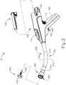
- FIGS. 1-2 depict an exemplary surgical circular stapling instrument (10) that may be used to provide an end-to-end anastomosis between two sections of an anatomical lumen such as a portion of a patient's digestive tract.
- Instrument (10) of this example comprises a handle assembly (100), a shaft assembly (200), a stapling head assembly (300), an anvil (400), and a removable battery pack (120). Each of these components will be described in greater detail below. It should be understood that, in addition to or in lieu of the following, instrument (10) may be further constructed and operable in accordance with at least some of the teachings of U.S. Pat. App. No.
- anvil (400) of the present example comprises a head (410) and a shank (420).
- Head (410) includes a proximal surface (412) that defines a plurality of staple forming pockets (414).
- Staple forming pockets (414) are arranged in two concentric annular arrays in the present example.
- Staple forming pockets (414) are configured to deform staples as the staples are driven into staple forming pockets (414) (e.g., deforming a generally "U" shaped staple into a "B" shape as is known in the art).
- Shank (420) defines a bore or lumen (422) and includes a pair of pivoting latch members (430) positioned in bore (422).
- Each latch member (430) includes features that allows anvil (400) to be removably secured to a trocar (330) of stapling head assembly (300) as will be described in greater detail below. It should be understood, however, that anvil (400) may be removably secured to a trocar (330) using any other suitable components, features, or techniques.
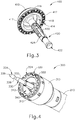
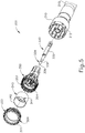
- Stapling head assembly (300) is located at the distal end of shaft assembly (200). As shown in FIGS. 1-2 , anvil (400) is configured to removably couple with shaft assembly (200), adjacent to stapling head assembly (300). As will be described in greater detail below, anvil (400) and stapling head assembly (300) are configured to cooperate to manipulate tissue in three ways, including clamping the tissue, cutting the tissue, and stapling the tissue. As best seen in FIGS. 4-5 , stapling head assembly (300) of the present example comprises a tubular casing (310) housing a slidable staple driver member (350). A cylindraceous inner core member (312) extends distally within tubular casing (310). Tubular casing (310) is fixedly secured to an outer sheath (210) of shaft assembly (200), such that tubular casing (310) serves as a mechanical ground for stapling head assembly (300).
- Trocar (330) is positioned coaxially within inner core member (312) of tubular casing (310). Trocar (330) is operable to translate distally and proximally relative to tubular casing (310) in response to rotation of a knob (130) located at the proximal end of handle assembly (100).
- Trocar (330) comprises a shaft (332) and ahead (334).
- Head (334) includes a pointed tip (336) and an inwardly extending proximal surface (338). Head (334) and the distal portion of shaft (332) are configured for insertion in bore (422) of anvil (420).
- Proximal surface (338) is configured to complement features of latch members (430) to provide a snap fit between anvil (400) and trocar (330).
- Staple driver member (350) is operable to actuate longitudinally within tubular casing (310) in response to activation of motor (160) as will be described in greater detail below.
- Staple driver member (350) includes two distally presented concentric annular arrays of staple drivers (352).
- Staple drivers (352) are arranged to correspond with the arrangement of staple forming pockets (414) described above.
- each staple driver (352) is configured to drive a corresponding staple into a corresponding staple forming pocket (414) when stapling head assembly (300) is actuated.
- Staple driver member (350) also defines a bore (354) that is configured to coaxially receive core member (312) of tubular casing (310).
- Knife member (340) is coaxially positioned within staple driver member (350).
- Knife member (340) includes a distally presented, sharp circular cutting edge (342).
- Knife member (340) is sized such that knife member (340) defines an outer diameter that is smaller than the diameter defined by the inner annular array of staple drivers (352).
- Knife member (340) also defines an opening that is configured to coaxially receive core member (312) of tubular casing (310).
- a deck member (320) is fixedly secured to tubular casing (310).
- Deck member (320) includes a distally presented deck surface (322) defining two concentric annular arrays of staple openings (324).
- Staple openings (324) are arranged to correspond with the arrangement of staple drivers (352) and staple forming pockets (414) described above.
- each staple opening (324) is configured to provide a path for a corresponding staple driver (352) to drive a corresponding staple through deck member (320) and into a corresponding staple forming pocket (414) when stapling head assembly (300) is actuated.
- the arrangement of staple openings (322) may be modified just like the arrangement of staple forming pockets (414) as described above.
- Deck member (320) defines an inner diameter that is just slightly larger than the outer diameter defined by knife member (340). Deck member (320) is thus configured to allow knife member (340) to translate distally to a point where cutting edge (342) is distal to deck surface (322).
- FIG. 6 shows various components of shaft assembly (200), which extends distally from handle assembly (100) and couples components of stapling head assembly (300) with components of handle assembly (100).
- shaft assembly (200) includes an outer sheath (210) that extends between handle assembly (100) and tubular casing (310).
- outer sheath (210) is rigid and includes a preformed curved section (212) that is configured to facilitate positioning of stapling head assembly (300) within a patient's colon as described below.
- Curved section (212) includes an inner curve (216) and an outer curve (214).
- Shaft assembly (200) further includes a trocar actuation rod (220) and a trocar actuation band assembly (230).
- the distal end of trocar actuation band assembly (230) is fixedly secured to the proximal end of trocar shaft (332).
- the proximal end of trocar actuation band assembly (230) is fixedly secured to the distal end of trocar actuation rod (220), such that trocar (330) will translate longitudinally relative to outer sheath (210) in response to translation of trocar actuation band assembly (230) and trocar actuation rod (220) relative to outer sheath (210).
- Trocar actuation band assembly (230) is configured to flex such that trocar actuation band assembly (230) may follow along the preformed curve in shaft assembly (200) as trocar actuation band assembly (230) is translated longitudinally relative to outer sheath (210).
- trocar actuation band assembly (230) has sufficient column strength and tensile strength to transfer distal and proximal forces from trocar actuation rod (220) to trocar shaft (332).
- Trocar actuation rod (220) is rigid.
- a clip (222) is fixedly secured to trocar actuation rod (220) and is configured to cooperate with complementary features within handle assembly (100) to prevent trocar actuation rod (220) from rotating within handle assembly (100) while still permitting trocar actuation rod (220) to translate longitudinally within handle assembly (100).
- Trocar actuation rod (220) further includes a coarse helical threading (224) and a fine helical threading (226).
- Shaft assembly (200) further includes a stapling head assembly driver (240) that is slidably received within outer sheath (210).
- the distal end of stapling head assembly driver (240) is fixedly secured to the proximal end of staple driver member (350).
- the proximal end of stapling head assembly driver (240) is secured to a drive bracket (250) via a pin (242). It should therefore be understood that staple driver member (350) will translate longitudinally relative to outer sheath (210) in response to translation of stapling head assembly driver (240) and drive bracket (250) relative to outer sheath (210).
- Stapling head assembly driver (240) is configured to flex such that stapling head assembly driver (240) may follow along the preformed curve in shaft assembly (200) as stapling head assembly driver (240) is translated longitudinally relative to outer sheath (210). However, stapling head assembly driver (240) has sufficient column strength to transfer distal forces from drive bracket (250) to staple driver member (350).
- handle assembly (100) includes a pistol grip (112) and several components that are operable to actuate anvil (400) and stapling head assembly (300).
- handle assembly (100) includes knob (130), a safety trigger (140) a firing trigger (150), a motor (160), and a motor activation module (180).
- Knob (130) is coupled with trocar actuation rod (220) via a nut (not shown), such that coarse helical threading (224) will selectively engage a thread engagement feature within the interior of the nut; and such that fine helical threading (226) will selectively engage a thread engagement feature within the interior of knob (130).
- These complementary structures are configured such that trocar actuation rod (220) will first translate proximally at a relatively slow rate, then translate proximally at a relatively fast rate, in response to rotation of knob (130).
- knob (130) when anvil (400) is coupled with trocar (330), rotation of knob (130) will provide corresponding translation of anvil relative to stapling head assembly (300). It should also be understood that knob (130) may be rotated in a first angular direction (e.g., clockwise) to retract anvil (400) toward stapling head assembly (300); and in a second angular direction (e.g., counterclockwise) to advance anvil (500) away from stapling head assembly (300). Knob (130) may thus be used to adjust the gap distance between opposing surfaces (412, 322) of anvil (400) and stapling head assembly (300) until a suitable gap distance has been achieved.
- first angular direction e.g., clockwise
- a second angular direction e.g., counterclockwise
- handle assembly (100) comprises a user feedback feature (114) that is configured to provide the operator with visual feedback indicating the positioning of anvil (400) in relation to stapling assembly (300). The operator may thus observe user feedback feature (114) while rotating knob (130), to confirm whether the suitable gap distance between anvil (400) and stapling assembly (300) has been achieved.
- user feedback feature (114) may be configured and operable in accordance with at least some of the teachings of U.S. Pat. App. No. 14/751,612 , entitled “Method of Applying an Annular Array of Staples to Tissue," filed June 26, 2015, the disclosure of which is incorporated by reference herein. Other suitable forms of providing user feedback will be apparent to those of ordinary skill in the art in view of the teachings herein.
- Firing trigger (150) is operable to activate motor (160) to thereby actuate stapling head assembly (300).
- Safety trigger (140) is operable to selectively block actuation of firing trigger (150) based on the longitudinal position of anvil (400) in relation to stapling head assembly (300).
- Handle assembly (100) also includes components that are operable to selectively lock out both triggers (140, 150) based on the position of anvil (400) relative to stapling head assembly (300). When triggers (140, 150) are locked out, firing trigger (150) is prevented from initiating actuation of stapling head assembly (300).
- trigger (150) is only operable to initiate actuation of stapling head assembly (300) when the position of anvil (400) relative to stapling head assembly (300) is within a predefined range.
- firing trigger (150) of the present example includes an integral actuation paddle, such as the paddle shown and described in U.S. Patent App. No. 14/751,231 , entitled “Surgical Stapler with Reversible Motor,” filed June 26, 2015, the disclosure of which is incorporated by reference herein.
- the paddle is configured to actuate a switch of motor activation module (180) ( FIG. 1 ) when firing trigger (150) is pivoted to a fired position.
- Motor activation module (180) is in communication with battery pack (120) and motor (160), such that motor activation module (180) is configured to provide activation of motor (160) with electrical power from battery pack (120) in response to the paddle actuating the switch of motor activation module (180).
- motor (160) will be activated when firing trigger (150) is pivoted. This activation of motor (160) will actuate stapling head assembly (300) as described in greater detail below.
- Battery pack (120) is operable to provide electrical power to a motor (160) as noted above.
- Battery pack (120) may be removably coupled with handle assembly (100) through a snap fit or in any other suitable fashion.
- battery pack (120) and handle assembly (100) may have complementary electrical contacts, pins and sockets, and/or other features that provide paths for electrical communication from battery pack (120) to electrically powered components in handle assembly (100) when battery pack (120) is coupled with handle assembly (100).
- battery pack (120) is unitarily incorporated within handle assembly (100) such that battery back (120) cannot be removed from handle assembly (100).
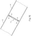
- FIGS. 7A-7E show instrument (10) being used to form an anastomosis (70) between two tubular anatomical structures (20, 40).
- the tubular anatomical structures (20, 40) may comprise sections of a patient's esophagus, sections of a patient's colon, other sections of the patient's digestive tract, or any other tubular anatomical structures.
- one or more diseased portions of a patient's colon are removed, with the tubular anatomical structures (20, 40) of FIGS. 7A-7E representing the remaining severed portions of the colon.
- anvil (400) is positioned in one tubular anatomical structure (20) and stapling head assembly (300) is positioned in another tubular anatomical structure (40).
- stapling head assembly (300) may be inserted via the patient's rectum.
- FIGS. 7A-7E is an open surgical procedure, though the procedure may instead be performed laparoscopically.
- the surgical procedure may be performed laparoscopically in accordance with at least some of the teachings of U.S. Pub. No.
- anvil (400) is positioned in tubular anatomical structure (20) such that shank (420) protrudes from the open severed end (22) of tubular anatomical structure (20).
- a purse-string suture (30) is provided about a mid-region of shank (420) to generally secure the position of anvil (400) in tubular anatomical structure (20).
- stapling head assembly (300) is positioned in tubular anatomical structure (40) such that trocar (330) protrudes from the open severed end (42) of tubular anatomical structure (20).
- a purse-string suture (50) is provided about a mid-region of shaft (332) to generally secure the position of stapling head assembly (300) in tubular anatomical structure (40).
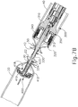
- anvil (400) is secured to trocar (330) by inserting trocar (330) into bore (422) as shown in FIG. 7B .
- Latch members (430) engage head (334) of trocar (330), thereby providing a secure fit between anvil (400) and trocar (330).
- the operator then rotates knob (130) while holding handle assembly (100) stationary via pistol grip (112). This rotation of knob (130) causes trocar (330) and anvil (400) to retract proximally, as described above. As shown in FIG.
- this proximal retraction of trocar (330) and anvil (400) compresses the tissue of tubular anatomical structures (20, 40) between surfaces (412, 322) of anvil (400) and stapling head assembly (300).
- the operator observes user feedback feature (114) to determine whether the gap distance (d) between opposing surfaces (412, 322) of anvil (400) and stapling head assembly (300) is appropriate; and makes any necessary adjustments via knob (130).
- the operator actuates safety trigger (140) to enable actuation of firing trigger (150).
- the operator then actuates firing trigger (150).
- This actuation of firing trigger (150) in turn actuates a switch of motor activation module (180), which in turn activates motor (160) to thereby actuate stapling head assembly (300) by driving knife member (340) and staple driver member (350) distally as shown in FIG. 7D .
- knife member (340) translates distally, cutting edge (342) of knife member (340) cooperates with inner edge (416) of anvil (400), thereby shearing excess tissue that is positioned within annular recess (418) of anvil (400) and the interior of knife member (340).
- anvil (400) of the present example includes a breakable washer (417) within annular recess (418).
- This washer (417) is broken by knife member (340) when knife member (340) completes a full distal range of motion from the position shown in FIG. 7C to the position shown in FIG. 7D .
- the drive mechanism for knife member (340) may provide an increasing mechanical advantage as knife member (340) reaches the end of its distal movement, thereby providing greater force by which to break washer (417).
- breakable washer (417) may be omitted entirely in some versions.
- washer (417) may also serve as a cutting board for knife member (340) to assist in cutting of tissue. Such a cutting technique may be employed in addition to or in lieu of the above-noted shearing action between inner edge (416) and cutting edge (342).
- staple driver member (350) drives staples (90) through the tissue of tubular anatomical structures (20, 40) and into staple forming pockets (414) of anvil (400). Staple forming pockets (414) deform the driven staples (90) into a "B" shape as is known in the art.
- the formed staples (90) thus secure the ends of tissue together, thereby coupling tubular anatomical structure (20) with tubular anatomical structure (40).
- instrument (10) may be removed via the patient's rectum. With instrument (10) removed, the tubular anatomical structures (20, 40) are left secured together by two annular arrays of staples (90) at an anastomosis (70) as shown in FIG. 7E .
- the inner diameter of the anastomosis (70) is defined by the severed edge (60) left by knife member (340).
- reconfiguring and rearranging staple forming pockets (414) may result in reconfiguration and rearrangement of staples (90) that are formed by staple forming pockets (414).
- the configuration and arrangement of staple forming pockets (414) may affect the structural integrity of an anastomosis (70) that is secured by staples (90).
- the configuration and arrangement of staple forming pockets (414) may affect the hemostasis that is achieved at an anastomosis (70) that is secured by staples (90).
- the following description relates to several exemplary variations of anvil (400), providing staple forming pocket configurations and arrangements that differ from those of staple forming pockets (414).
- FIGS. 8-10 show an exemplary alternative anvil (500) that may be used with a modified version of instrument (10).
- Anvil (500) of this example is configured and operable just like anvil (400), except for the differences described below.
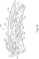
- Anvil (500) of the present example comprises a proximal surface (506) that defines an inner annular array (502) of staple forming pockets (510, 530) and an outer annular array (504) of staple forming pockets (550, 570).
- a chamfered edge (508) extends about the outer perimeter of proximal surface (506).
- anvil (500) may be secured to trocar (330), that proximal surface (506) may be used to compress tissue against deck surface (322), and that staple driver (352) may drive staples (90) through tissue into staple forming pockets (510, 530, 550, 570) in order to thereby form staples (90) in the tissue.
- each staple forming pocket (510) comprises a staple entry surface (512) and a staple exit surface (514).
- Surfaces (512, 514) are contiguous with each other and define a concave recess.
- the concave recess formed by surfaces (512, 514) is further defined by an inner wall (516), a first outer wall (518), a second outer wall (520), and a third outer wall (522).
- walls (516, 518, 520, 522) are each substantially flat.
- Wall (518) defines a relatively narrow, tapered gap with wall (516).
- Wall (522) defines a relatively wide gap with wall (516).
- Wall (520) is obliquely angled, providing an inwardly sloped transition from wall (522) to wall (518).
- walls (518, 520, 522) together provide a dogleg configuration.
- the edge connecting wall (516) with wall (522) is substantially straight in this example.
- the edge connecting wall (516) with wall (518) is substantially straight in this example.
- first leg of staple (90) when a first leg of staple (90) is driven into staple forming pocket (510), the first leg first encounters staple entry surface (512), bends generally toward the second leg of staple (90) along a first plane that is orthogonal to the axis of the unformed first leg, and then bends proximally back generally toward the crown of staple (90).
- first leg will eventually encounter wall (520), which will provide a cam surface bending the first leg along a second plane that is orthogonal to the axis of the unformed first leg.
- wall (520) and then wall (518) will deflect the first leg radially inwardly toward the central axis of anvil (500).
- staple forming pocket (510) will ultimately deflect a first leg of a staple (90) proximally and radially inwardly.
- Wall (516) will restrict the degree to which the first leg of staple (90) deflects radially inwardly.
- Each staple forming pocket (530) comprises a staple entry surface (532) and a staple exit surface (534).
- Surfaces (532, 534) are contiguous with each other and define a concave recess.
- the concave recess formed by surfaces (532, 534) is further defined by an outer wall (536), a first inner wall (538), a second inner wall (540), and a third inner wall (542).
- walls (536, 538, 540, 542) are each substantially flat.
- Wall (538) defines a relatively narrow, tapered gap with wall (536).
- Wall (542) defines a relatively wide gap with wall (536).
- Wall (540) is obliquely angled, providing an outwardly sloped transition from wall (542) to wall (538).
- walls (538, 540, 542) together provide a dogleg configuration.
- the edge connecting wall (536) with wall (542) is substantially straight in this example.
- the edge connecting wall (536) with wall (538) is substantially straight in this example
- a second leg of staple (90) when a second leg of staple (90) is driven into staple forming pocket (530), the second leg first encounters staple entry surface (532), bends generally toward the first leg of staple (90) along a first plane that is orthogonal to the axis of the unformed second leg, and then bends proximally back generally toward the crown of staple (90).
- the second leg will eventually encounter wall (540), which will provide a cam surface bending the second leg along a second plane that is orthogonal to the axis of the unformed second leg.
- wall (540) and then wall (538) will deflect the second leg radially outwardly away from the central axis of anvil (500).
- staple forming pocket (530) will ultimately deflect a second leg of a staple (90) proximally and radially outwardly.
- Wall (536) will restrict the degree to which the second leg of staple (90) deflects radially outwardly.
- Each staple forming pocket (550) comprises a staple entry surface (552) and a staple exit surface (554).
- Surfaces (552, 554) are contiguous with each other and define a concave recess.
- the concave recess formed by surfaces (552, 554) is further defined by an outer wall (556), a first inner wall (558), a second inner wall (560), and a third inner wall (562).
- walls (556, 558, 560, 562) are each substantially flat.
- Wall (558) defines a relatively narrow, tapered gap with wall (556).
- Wall (562) defines a relatively wide gap with wall (556).
- Wall (560) is obliquely angled, providing an outwardly sloped transition from wall (562) to wall (558).
- walls (558, 560, 562) together provide a dogleg configuration.
- the edge connecting wall (556) with wall (562) is substantially straight in this example.
- the edge connecting wall (556) with wall (558) is substantially straight in this example
- a second leg of staple (90) when driven into staple forming pocket (550), the second leg first encounters staple entry surface (552), bends generally toward the first leg of staple (90) along a first plane that is orthogonal to the axis of the unformed second leg, and then bends proximally back generally toward the crown of staple (90).
- the second leg will eventually encounter wall (560), which will provide a cam surface bending the second leg along a second plane that is orthogonal to the axis of the unformed second leg.
- wall (560) and then wall (558) will deflect the second leg radially outwardly away from the central axis of anvil (500).
- staple forming pocket (550) will ultimately deflect a second leg of a staple (90) proximally and radially outwardly.
- Wall (556) will restrict the degree to which the second leg of staple (90) deflects radially outwardly.
- Each staple forming pocket (570) comprises a staple entry surface (572) and a staple exit surface (574).
- Surfaces (572, 574) are contiguous with each other and define a concave recess.
- the concave recess formed by surfaces (572, 574) is further defined by an inner wall (576), a first outer wall (578), a second outer wall (580), and a third outer wall (582).
- walls (576, 578, 580, 582) are each substantially flat.
- Wall (578) defines a relatively narrow, tapered gap with wall (576).
- Wall (582) defines a relatively wide gap with wall (576).
- Wall (580) is obliquely angled, providing an inwardly sloped transition from wall (582) to wall (578).
- walls (578, 580, 582) together provide a dogleg configuration.
- the edge connecting wall (576) with wall (582) is substantially straight in this example.
- the edge connecting wall (576) with wall (578) is substantially
- first leg of staple (90) when driven into staple forming pocket (570), the first leg first encounters staple entry surface (572), bends generally toward the second leg of staple (90) along a first plane that is orthogonal to the axis of the unformed first leg, and then bends proximally back generally toward the crown of staple (90).
- first leg will eventually encounter wall (580), which will provide a cam surface bending the first leg along a second plane that is orthogonal to the axis of the unformed first leg.
- wall (580) and then wall (578) will deflect the first leg radially inwardly toward the central axis of anvil (500).
- staple forming pocket (570) will ultimately deflect a first leg of a staple (90) proximally and radially inwardly.
- Wall (576) will restrict the degree to which the first leg of staple (90) deflects radially inwardly.
- staple forming pockets (510, 530, 550, 570) are arranged such that a radius line (R L ) extending outwardly from the center of anvil (500) passes through the region of entry surface (512) of staple forming pocket (510) and through the region of entry surface (552) of staple forming pocket (550).
- a radius line (R L ) extending outwardly from the center of anvil (500) passes through the region of entry surface (512) of staple forming pocket (510) and through the region of entry surface (552) of staple forming pocket (550).
- another radius line (R L ) extending outwardly from the center of anvil (500) passes through the region of entry surface (532) of staple forming pocket (530) and through the region of entry surface (572) of staple forming pocket (570).
- staple forming pockets (530, 570) overlap along a radial dimension.
- another radius line (R L ) extending outwardly from the center of anvil (500) passes through the region of exit surface (574) of staple forming pocket (570) and through the region of exit surface (554) of staple forming pocket (550).
- staple forming pockets (550, 570) overlap along a radial dimension.
- staple forming pockets (550, 570) in each pair of pockets (550, 570) are interlocking in this configuration.
- another radius line (R L ) extending outwardly from the center of anvil (500) passes through the region of exit surface (514) of staple forming pocket (510) and through the region of exit surface (534) of staple forming pocket (530).
- staple forming pockets (510, 530) overlap along a radial dimension.
- staple forming pockets (510, 530) in each pair of pockets (510, 530) are interlocking in this configuration.
- inner array (502) and outer array (504) are configured similarly, such that the inner-most pocket (510) in each pair of inner pockets (510, 530) is on the left-hand side (in the view of FIG. 9 ) of the pair of pockets (510, 530); and such that the inner-most pocket (570) in each pair of outer pockets (550, 570) is on the left-hand side (in the view of FIG. 9 ) of the pair of pockets (550, 570).
- the end of wall (536) associated with staple entry surface (532) includes a bent region (537), which bends slightly inwardly toward the central region of anvil (500). It should be understood that this bent region (537) may be formed in order to maintain a minimum distance between wall (536) and wall (576), thereby maintaining a minimum distance between staple forming pocket (530) and staple forming pocket (570), which may further provide more reliable manufacturing of anvil (600). In addition, bent region (537) may provide different behavior of the second leg of the staple (90) that is formed by staple forming pocket (530).
- Such different behavior may relate to deflections in anvil (500) and/or a tilt that might result in the first and second legs of a given staple (90) contacting corresponding surfaces (512, 532) at different times during actuation of stapling head assembly (300).
- bent region (537) provides staple forming pocket (530) with a structural configuration that makes staple forming pocket (530) unique relative to the other staple forming pockets (510, 550, 570).
- staple forming pocket (510) is identical to the structural configuration of staple forming pocket (570); while the structural configuration of staple forming pocket (550) is the mirrored inverse of the structural configuration of staple forming pockets (510, 570).
- the spacing between pockets (510, 530) in each pair of pockets (510, 530) is equal to the spacing between pockets (550, 570) in each pair of pockets (550, 570). In some other versions, however, the spacing between pockets (510, 530) in each pair of pockets (510, 530) is smaller than the spacing between pockets (550, 570) in each pair of pockets (550, 570). In such versions, pockets (550, 570) may be used to form staples (90) having a longer crown width than the crown width of staples (90) that are formed using pockets (510, 530).
- the spacing between pockets (510, 530) in each pair of pockets (510, 530) may be larger than the spacing between pockets (550, 570) in each pair of pockets (550, 570).
- pockets (550, 570) may be used to form staples (90) having a shorter crown width than the crown width of staples (90) that are formed using pockets (510, 530).
- staple forming pockets (510, 530) are arranged such that they are not fully centered along a circumferential line (C L ) extending along surface (506) at a constant radius from the center of anvil (500).
- the outermost regions of staple entry surfaces (512, 532) are radially centered along the same circumferential line (C L ).
- staple forming pocket (510) is oriented substantially obliquely relative to circumferential line (C L ), such that staple exit surface (514) is positioned substantially radially inwardly from circumferential line (C L ).
- staple exit surface (534) is positioned substantially along, with a portion position slightly radially outwardly from, circumferential line (C L ).
- staple forming pocket (530) is substantially aligned along circumferential line (C L )
- staple forming pocket (510) is substantially tilted radially inwardly relative to circumferential line (C L ), with the outermost regions of staple entry surfaces (512, 532) being radially centered along a circumferential line (C L ).
- FIGS. 9-10 While the views depicted in FIGS. 9-10 only show a portion of the full circumference of anvil (500), it should be understood that the structures depicted in FIGS. 9-10 extend along the full circumference of anvil (500). The views of FIGS. 9-10 are simply being provided as an enlargement to show the structure in further detail, and are not intended to suggest that the depicted structures are only located in a limited angular range along the circumference of anvil (500).
- FIG. 11 shows another exemplary alternative anvil (600) that may be used with a modified version of instrument (10).
- Anvil (600) of this example is configured and operable just like anvil (400), except for the differences described below.
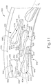
- Anvil (600) of the present example comprises a proximal surface (606) that defines an inner annular array (602) of staple forming pockets (610, 630) and an outer annular array (604) of staple forming pockets (650, 670).
- a chamfered edge (608) extends about the outer perimeter of proximal surface (606).
- anvil (600) may be secured to trocar (330), that proximal surface (606) may be used to compress tissue against deck surface (322), and that staple driver (352) may drive staples (90) through tissue into staple forming pockets (610, 630, 650, 670) in order to thereby form staples (90) in the tissue.
- each staple forming pocket (610) comprises a staple entry surface (612) and a staple exit surface (614).
- Surfaces (612, 614) are contiguous with each other and define a concave recess.
- the concave recess formed by surfaces (612, 614) is further defined by an inner wall (616), a first outer wall (618), a second outer wall (620), and a third outer wall (622).
- walls (616, 618, 620, 622) are each substantially flat.
- Wall (618) defines a relatively narrow, tapered gap with wall (616).
- Wall (622) defines a relatively wide gap with wall (616).
- Wall (620) is obliquely angled, providing an inwardly sloped transition from wall (622) to wall (618).
- walls (618, 620, 622) together provide a dogleg configuration.
- the edge (624) connecting wall (616) with wall (622) is substantially round in this example.
- the edge (626) connecting wall (616) with wall (618) is substantially round in this example.
- staple forming pocket (610) differs from staple forming pocket (510) in that edges (624,626) of staple forming pocket (610) are round; while the same edges in staple forming pocket (510) are substantially straight.
- first leg of staple (90) when a first leg of staple (90) is driven into staple forming pocket (610), the first leg first encounters staple entry surface (612), bends generally toward the second leg of staple (90) along a first plane that is orthogonal to the axis of the unformed first leg, and then bends proximally back generally toward the crown of staple (90).
- first leg will eventually encounter wall (620), which will provide a cam surface bending the first leg along a second plane that is orthogonal to the axis of the unformed first leg.
- wall (620) and then wall (618) will deflect the first leg radially inwardly toward the central axis of anvil (600).
- staple forming pocket (610) will ultimately deflect a first leg of a staple (90) proximally and radially inwardly.
- Wall (616) will restrict the degree to which the first leg of staple (90) deflects radially inwardly.
- Each staple forming pocket (630) comprises a staple entry surface (632) and a staple exit surface (634).
- Surfaces (632, 634) are contiguous with each other and define a concave recess.
- the concave recess formed by surfaces (632, 634) is further defined by an outer wall (636), a first inner wall (638), a second inner wall (640), and a third inner wall (642).
- walls (636, 638, 640, 642) are each substantially flat.
- Wall (638) defines a relatively narrow, tapered gap with wall (636).
- Wall (642) defines a relatively wide gap with wall (636).
- Wall (640) is obliquely angled, providing an outwardly sloped transition from wall (642) to wall (638).
- walls (638, 640, 642) together provide a dogleg configuration.
- a second leg of staple (90) when a second leg of staple (90) is driven into staple forming pocket (630), the second leg first encounters staple entry surface (632), bends generally toward the first leg of staple (90) along a first plane that is orthogonal to the axis of the unformed second leg, and then bends proximally back generally toward the crown of staple (90).
- the second leg will eventually encounter wall (640), which will provide a cam surface bending the second leg along a second plane that is orthogonal to the axis of the unformed second leg.
- wall (640) and then wall (638) will deflect the second leg radially outwardly away from the central axis of anvil (600).
- staple forming pocket (630) will ultimately deflect a second leg of a staple (90) proximally and radially outwardly.
- Wall (636) will restrict the degree to which the second leg of staple (90) deflects radially outwardly.
- Each staple forming pocket (650) comprises a staple entry surface (652) and a staple exit surface (654).
- Surfaces (652, 654) are contiguous with each other and define a concave recess.
- the concave recess formed by surfaces (652, 654) is further defined by an outer wall (656), a first inner wall (658), a second inner wall (660), and a third inner wall (662).
- walls (656, 658, 660, 662) are each substantially flat.
- Wall (658) defines a relatively narrow, tapered gap with wall (656).
- Wall (662) defines a relatively wide gap with wall (656).
- Wall (660) is obliquely angled, providing an outwardly sloped transition from wall (662) to wall (658).
- walls (658, 660, 662) together provide a dogleg configuration.
- the edge connecting wall (656) with wall (662) is substantially straight in this example.
- the edge connecting wall (656) with wall (658) is substantially straight in
- a second leg of staple (90) when driven into staple forming pocket (650), the second leg first encounters staple entry surface (652), bends generally toward the first leg of staple (90) along a first plane that is orthogonal to the axis of the unformed second leg, and then bends proximally back generally toward the crown of staple (90).
- the second leg will eventually encounter wall (660), which will provide a cam surface bending the second leg along a second plane that is orthogonal to the axis of the unformed second leg.
- wall (660) and then wall (658) will deflect the second leg radially outwardly away from the central axis of anvil (600).
- staple forming pocket (650) will ultimately deflect a second leg of a staple (90) proximally and radially outwardly.
- Wall (656) will restrict the degree to which the second leg of staple (90) deflects radially outwardly.
- Each staple forming pocket (670) comprises a staple entry surface (672) and a staple exit surface (674).
- Surfaces (672, 674) are contiguous with each other and define a concave recess.
- the concave recess formed by surfaces (672, 674) is further defined by an inner wall (676), a first outer wall (678), a second outer wall (680), and a third outer wall (682).
- walls (676, 678, 680, 682) are each substantially flat.
- Wall (678) defines a relatively narrow, tapered gap with wall (676).
- Wall (682) defines a relatively wide gap with wall (676).
- Wall (680) is obliquely angled, providing an inwardly sloped transition from wall (682) to wall (678).
- walls (678, 680, 682) together provide a dogleg configuration.
- the edge connecting wall (676) with wall (682) is substantially straight in this example.
- the edge connecting wall (676) with wall (678) is substantially
- first leg of staple (90) when a first leg of staple (90) is driven into staple forming pocket (670), the first leg first encounters staple entry surface (672), bends generally toward the second leg of staple (90) along a first plane that is orthogonal to the axis of the unformed first leg, and then bends proximally back generally toward the crown of staple (90).
- first leg will eventually encounter wall (680), which will provide a cam surface bending the first leg along a second plane that is orthogonal to the axis of the unformed first leg.
- wall (680) and then wall (678) will deflect the first leg radially inwardly toward the central axis of anvil (600).
- staple forming pocket (670) will ultimately deflect a first leg of a staple (90) proximally and radially inwardly.
- Wall (676) will restrict the degree to which the first leg of staple (90) deflects radially inwardly.
- FIG. 11 only shows a portion of anvil (600), it should be understood that staple forming pockets (610, 630, 650, 670) may span about the full circumference of proximal surface (606), in an arrangement like staple forming pockets (510, 530, 550, 570) as shown in FIG. 8 .
- staple forming pockets (610, 630, 650, 670) may have the same kind of overlap along a radial dimension as described above in the context of staple forming pockets (510, 530, 550, 570).
- the view depicted in FIG. 11 only shows a portion of the full circumference of anvil (600), it should be understood that the structures depicted in FIG. 11 extend along the full circumference of anvil (600).
- the view of FIG. 11 is simply being provided as an enlargement to show the structure in further detail, and is not intended to suggest that the depicted structures are only located in a limited angular range along the circumference of anvil (600).
- inner array (602) and outer array (604) are configured similarly, such that the inner-most pocket (610) in each pair of inner pockets (610, 630) is on the left-hand side (in the view of FIG. 11 ) of the pair of pockets (610, 630); and such that the inner-most pocket (670) in each pair of outer pockets (650, 670) is on the left-hand side (in the view of FIG. 11 ) of the pair of pockets (650, 670).
- staple forming pocket (630) is unique relative to the other staple forming pockets (610, 650, 670) of anvil (600) in that staple forming pocket (630) further includes a double-chamfered edge at the right-hand end (in the view of FIG. 11 ) of wall (636).
- this double-chamfered edge is formed by a first edge (648) that extends obliquely from wall (636); and a second edge (646) that extends obliquely from first edge (648).
- Second edge (646) is joined to wall (642) via a substantially flat edge (644).
- edges (646, 648) may serve a purpose similar to that described above in the context of bent region (537) of staple forming pocket (530).
- the configuration of edges (646, 648) may be formed in order to maintain a minimum distance between wall (636) and wall (676), thereby maintaining a minimum distance between staple forming pocket (630) and staple forming pocket (670), which may further provide more reliable manufacturing of anvil (600).
- the configuration of edges (646, 648) may provide different behavior of the second leg of the staple (90) that is formed by staple forming pocket (630).
- Such different behavior may relate to deflections in anvil (600) and/or a tilt that might result in the first and second legs of a given staple (90) contacting corresponding surfaces (612, 632) at different times during actuation of stapling head assembly (300).
- staple forming pockets (610, 630) are arranged such that they are not fully centered along a circumferential line (C L ) extending along surface (606) at a constant radius from the center of anvil (600).
- the outermost regions of staple entry surfaces (612, 632) are radially centered along the same circumferential line (C L ).
- staple forming pocket (610) is oriented substantially obliquely relative to circumferential line (C L ), such that staple exit surface (614) is positioned substantially radially inwardly from circumferential line (C L ).
- staple exit surface (634) is positioned substantially along, with a portion position slightly radially outwardly from, circumferential line (C L ).
- staple forming pocket (630) is substantially aligned along circumferential line (C L )
- staple forming pocket (510) is substantially tilted radially inwardly relative to circumferential line (C L ), with the outermost regions of staple entry surfaces (612, 632) being radially centered along a circumferential line (C L ).
- FIGS. 12-14 show an exemplary alternative anvil (700) that may be used with a modified version of instrument (10).
- Anvil (700) of this example is configured and operable just like anvil (400), except for the differences described below.
- Anvil (700) of the present example comprises a proximal surface (706) that defines an inner annular array (702) of staple forming pockets (710, 730) and an outer annular array (704) of staple forming pockets (750, 770).
- a chamfered edge (708) extends about the outer perimeter of proximal surface (706).
- anvil (700) may be secured to trocar (330), that proximal surface (706) may be used to compress tissue against deck surface (322), and that staple driver (352) may drive staples (90) through tissue into staple forming pockets (710, 730, 750, 770) in order to thereby form staples (90) in the tissue.
- each staple forming pocket (710) comprises a staple entry surface (712) and a staple exit surface (714).
- Surfaces (712, 714) are contiguous with each other and define a concave recess.
- the concave recess formed by surfaces (712, 714) is further defined by an inner wall (716) and an outer wall (718).
- walls (716, 718) are each substantially flat. Walls (716, 718) together define a taper, such that the gap between walls (716, 718) is smaller near exit surface (714) than the gap between walls (716, 718) at entry surface (712).
- first leg of staple (90) when a first leg of staple (90) is driven into staple forming pocket (710), the first leg first encounters staple entry surface (712), bends generally toward the second leg of staple (90) along a first plane that is orthogonal to the axis of the unformed first leg, and then bends proximally back generally toward the crown of staple (90).
- first leg will eventually encounter wall (716), which will provide a cam surface bending the first leg along a second plane that is orthogonal to the axis of the unformed first leg.
- wall (716) will deflect the first leg radially outwardly away from the central axis of anvil (700).
- staple forming pocket (710) will ultimately deflect a first leg of a staple (90) proximally and radially outwardly.
- Wall (718) will restrict the degree to which the first leg of staple (90) deflects radially outwardly.
- Each staple forming pocket (730) comprises a staple entry surface (732) and a staple exit surface (734).
- Surfaces (732, 734) are contiguous with each other and define a concave recess.
- the concave recess formed by surfaces (732, 734) is further defined by an inner wall (738) and an outer wall (736).
- walls (736, 738) are each substantially flat. Walls (736, 738) together define a taper, such that the gap between walls (736, 738) is smaller near exit surface (734) than the gap between walls (736, 738) at entry surface (732).
- staple forming pocket (730) will ultimately deflect a second leg of a staple (90) proximally and radially inwardly.
- Wall (738) will restrict the degree to which the second leg of staple (90) deflects radially inwardly.
- Each staple forming pocket (750) comprises a staple entry surface (752) and a staple exit surface (754).
- Surfaces (752, 754) are contiguous with each other and define a concave recess.
- the concave recess formed by surfaces (752, 754) is further defined by an inner wall (758) and an outer wall (756).
- walls (756, 758) are each substantially flat. Walls (756, 758) together define a taper, such that the gap between walls (756, 758) is smaller near exit surface (754) than the gap between walls (756, 758) at entry surface (752).
- a second leg of staple (90) when a second leg of staple (90) is driven into staple forming pocket (750), the second leg first encounters staple entry surface (752), bends generally toward the first leg of staple (90) along a first plane that is orthogonal to the axis of the unformed second leg, and then bends proximally back generally toward the crown of staple (90).
- the second leg will eventually encounter wall (758), which will provide a cam surface bending the second leg along a second plane that is orthogonal to the axis of the unformed second leg.
- wall (758) will deflect the second leg radially outwardly away from the central axis of anvil (700).
- staple forming pocket (750) will ultimately deflect a second leg of a staple (90) proximally and radially outwardly.
- Wall (756) will restrict the degree to which the second leg of staple (90) deflects radially outwardly.
- Each staple forming pocket (770) comprises a staple entry surface (772) and a staple exit surface (774).
- Surfaces (772, 774) are contiguous with each other and define a concave recess.
- the concave recess formed by surfaces (772, 774) is further defined by an inner wall (776) and an outer wall (778).
- walls (776, 778) are each substantially flat. Walls (776, 778) together define a taper, such that the gap between walls (776, 778) is smaller near exit surface (774) than the gap between walls (776, 778) at entry surface (772).
- first leg of staple (90) when a first leg of staple (90) is driven into staple forming pocket (770), the first leg first encounters staple entry surface (772), bends generally toward the second leg of staple (90) along a first plane that is orthogonal to the axis of the unformed first leg, and then bends proximally back generally toward the crown of staple (90).
- first leg will eventually encounter wall (778), which will provide a cam surface bending the first leg along a second plane that is orthogonal to the axis of the unformed first leg.
- wall (778) will deflect the first leg radially inwardly toward the central axis of anvil (700).
- staple forming pocket (770) will ultimately deflect a first leg of a staple (90) proximally and radially inwardly.
- Wall (776) will restrict the degree to which the first leg of staple (90) deflects radially inwardly.
- staple forming pockets (710, 730, 750, 770) are arranged such that a radius line (R L ) extending outwardly from the center of anvil (700) passes through the region of exit surface (774) of staple forming pocket (770) and through the region of exit surface (754) of staple forming pocket (750).
- R L radius line
- staple forming pockets (750, 770) overlap along a radial dimension. It should also be understood that staple forming pockets (750, 770) in each pair of pockets (750, 770) are interlocking in this configuration.
- another radius line (R L ) extending outwardly from the center of anvil (700) passes through the region of exit surface (714) of staple forming pocket (710) and through the region of exit surface (734) of staple forming pocket (730).
- staple forming pockets (710, 730) overlap along a radial dimension.
- staple forming pockets (710, 730) in each pair of pockets (710, 730) are interlocking in this configuration.
- another radius line (R L ) extending outwardly from the center of anvil (700) passes through the region of entry surface (732) of staple forming pocket (730) and through the region of entry surface (772) of staple forming pocket (770).
- staple forming pockets (730, 770) overlap along a radial dimension.
- another radius line (R L ) extending outwardly from the center of anvil (700) passes through the region of entry surface (712) of staple forming pocket (710) and through the region of entry surface (752) of staple forming pocket (750).
- staple forming pockets (710, 750) overlap along a radial dimension.
- inner array (702) and outer array (704) are arranged to provide mirrored symmetry, such that the outer-most pocket (710) in each pair of inner pockets (710, 730) is on the left-hand side (in the view of FIGS. 13-14 ) of the pair of pockets (710, 730); and such that the inner-most pocket (770) in each pair of outer pockets (750, 770) is on the left-hand side (in the view of FIGS. 13-14 ) of the pair of pockets (750, 770).
- the symmetry between arrays (702, 704) is opposite of the symmetry between arrays (502, 504) described above.
- staple forming pockets (710, 730) are arranged such that they are substantially centered along a circumferential line (C L ) extending along surface (706) at a constant radius from the center of anvil (700).
- the outermost regions of staple entry surfaces (712, 732) are radially centered along the same circumferential line (C L ).
- circumferential line (C L ) intersects wall (716) at a point along the length of wall (716) that is at the same point along the length of wall (736) at which circumferential line (C L ) intersects wall (736).
- staple forming pockets (710, 730) are radially centered along circumferential line (C L ).
- FIGS. 13-14 While the views depicted in FIGS. 13-14 only show a portion of the full circumference of anvil (700), it should be understood that the structures depicted in FIGS. 13-14 extend along the full circumference of anvil (700). The views of FIGS. 13-14 are simply being provided as an enlargement to show the structure in further detail, and are not intended to suggest that the depicted structures are only located in a limited angular range along the circumference of anvil (700).
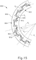
- FIG. 15 shows another exemplary alternative anvil (800) that may be used with a modified version of instrument (10).
- Anvil (800) of this example is configured and operable just like anvil (400), except for the differences described below.
- Anvil (800) of the present example comprises a proximal surface (806) that defines an inner annular array (802) of staple forming pockets (810, 830) and an outer annular array (804) of staple forming pockets (850, 870).
- a chamfered edge extends about the outer perimeter of proximal surface (806).
- anvil (800) may be secured to trocar (330), that proximal surface (806) may be used to compress tissue against deck surface (322), and that staple driver (352) may drive staples (880, 890) through tissue into staple forming pockets (810, 830, 850, 870) in order to thereby form staples (880, 890) in the tissue.
- the structural configuration of staple forming pocket (810) is identical to the structural configuration of staple forming pocket (710)
- the structural configuration of staple forming pocket (830) is identical to the structural configuration of staple forming pocket (730)
- the structural configuration of staple forming pocket (850) is identical to the structural configuration of staple forming pocket (750)
- the structural configuration of staple forming pocket (870) is identical to the structural configuration of staple forming pocket (770).
- the structural configurations of (810, 830, 850, 870) will not be discussed in further detail here.
- the positioning and arrangement of staple forming pockets (810, 830) is identical to the positioning and arrangement of staple forming pockets (710, 730).
- the relationship between staple forming pockets (810, 830) and a circumferential line (C L ) is the same as the above-noted relationship between forming pockets (710, 730) and a corresponding circumferential line (C L ).
- staple forming pockets (850, 870) are arranged such that they do not overlap each other. Instead, staple forming pockets (850, 870) are aligned with each other such that a circumferential line (C L ) is centered along the staple entry and staple exit surfaces of staple forming pockets (750, 770).
- staple forming pockets (810, 830, 850, 870) are arranged such that a radius line (R L ) extending outwardly from the center of anvil (800) passes through a staple forming pocket (830) and an adjacent staple forming pocket (870); such that another radius line (R L ) extending outwardly from the center of anvil (800) passes through a staple forming pocket (810) and an adjacent staple forming pocket (850); and such that another radius line (R L ) extending outwardly from the center of anvil (800) passes through both staple forming pockets (810, 830) in each pair of staple forming pockets (810, 830).
- FIG. 15 shows one radius line (R L ) extending outwardly from the center of anvil (800) passing between forming pockets (850, 870).
- FIG. 15 While the view depicted in FIG. 15 only shows a portion of the full circumference of anvil (800), it should be understood that the structures depicted in FIG. 15 extend along the full circumference of anvil (800).
- the view of FIG. 15 is simply being provided as an enlargement to show the structure in further detail, and is not intended to suggest that the depicted structures are only located in a limited angular range along the circumference of anvil (800).
- FIGS. 16-17 show two arrays of staples (880, 890) that have been formed using anvil (800).
- FIGS. 16-17 show an inner array of staples (880) formed by staple forming pockets (810, 830) and an outer array of staples (890) formed by staple forming pockets (850, 870).
- each outer staple (890) includes a crown (892) and an associated pair of bent legs (894, 896). Since the staple entry and exit regions of staple forming pockets (850, 870) are centered along a circumferential line (C L ), the crowns (892) and bent legs (894, 896) are also centered along a circumferential line (C L ).
- formed staples (890) are substantially two-dimensional-extending along a circumferential dimension (i.e., along circumferential line (C L )) and extending along a longitudinal dimension (i.e., into and out of the page in the view of FIG. 16 ).
- This two-dimensional configuration of formed staples (890) provides an appearance similar to the letter "B.”
- each inner staple (880) includes bent legs (884, 886) that are deflected off-plane from the corresponding crown (882).
- crowns (882) are substantially centered along circumferential line (C L )
- each bent leg (884) is deflected radially inwardly relative to circumferential line (C L ) while each bent leg (886) is deflected radially outwardly relative to circumferential line (C L ).
- This configuration is due to the offset relationship between staple forming pockets (810, 830) and a corresponding circumferential line (C L ).
- staples formed by staple forming pockets may also have a configuration that is similar to formed staples (880).
- formed staples (880) are substantially three-dimensional-extending along a circumferential dimension (i.e., along circumferential line (C L )), extending along a longitudinal dimension (i.e., into and out of the page in the view of FIG. 16 ), and extending along a radial dimension.
- FIG. 18 shows another exemplary alternative anvil (900) that may be used with a modified version of instrument (10).
- Anvil (900) of this example is configured and operable just like anvil (400), except for the differences described below.
- Anvil (800) of the present example comprises a proximal surface (906) that defines an inner annular array (902) of staple forming pockets (910, 930) and an outer annular array (904) of staple forming pockets (950, 970).
- a chamfered edge extends about the outer perimeter of proximal surface (906).
- anvil (900) may be secured to trocar (330), that proximal surface (906) may be used to compress tissue against deck surface (322), and that staple driver (352) may drive staples (980, 990) through tissue into staple forming pockets (910, 930, 950, 970) in order to thereby form staples (980, 990) in the tissue.
- all staple forming pockets (910, 930, 950, 970) are configured identically to each other.
- each staple forming pocket (910, 930, 950, 970) has a generally rectangular shape at proximal surface (906), such that staple forming pockets (910, 930, 950, 970) are not tapered along proximal surface (906).
- the sidewalls of staple forming pockets (910, 930, 950, 970) slope toward each other as the sidewalls approach the floors of staple forming pockets (910, 930, 950, 970).
- the floors of staple forming pockets (910, 930, 950, 970) are concave, such that a staple leg (984, 986, 994, 996) will first encounter a corresponding staple entry point (912, 932, 952, 972), then bend generally toward the other leg of staple (980, 990) along a first plane that is orthogonal to the axis of the unformed first leg, and then bend proximally back generally toward the crown (982, 992) of staple (980, 990).
- each pair of staple forming pockets (910, 930) is centered along a corresponding circumferential line (C L ), and each pair of staple forming pockets (950, 970) is also centered along a corresponding circumferential line (C L ).
- an inner circumferential line (C L ) passes through each staple entry point (912, 932); while an outer circumferential line (C L ) passes through each staple entry point (952, 972).
- each staple forming pocket (910, 930, 950, 970), as pairs, are centered along corresponding circumferential lines (C L )
- each staple forming pocket (910, 930, 950, 970) is oriented obliquely relative to the corresponding circumferential line (C L ).
- each staple forming pocket (910) is angularly offset relative to the other staple forming pocket (930) in the pair of pockets (910, 930); and each staple forming pocket (950) is angularly offset relative to the other staple forming pocket (970) in the pair of pockets (950, 970).
- staple forming pockets (910, 930, 950, 970) will bend legs (984, 986, 994, 996) along respective second planes that are orthogonal to the respective axes of the respective unformed first legs (984, 986, 994, 996).
- staple forming pocket (910) will bend leg (984) radially outwardly away from the central axis of anvil (900); staple forming pocket (930) will bend leg (986) radially inwardly toward the central axis of anvil (900); staple forming pocket (950) will bend leg (994) radially outwardly away from the central axis of anvil (900); and staple forming pocket (970) will bend leg (996) radially inwardly toward the central axis of anvil (900).
- inner array (902) and outer array (904) are arranged to provide mirrored symmetry, such that the pocket (910) in each pair of inner pockets (910, 930) providing the outer-most formed leg (984) is on the bottom (in the view of FIG. 18 ) of the pair of pockets (910, 930); and such that pocket (970) in each pair of outer pockets (950, 970) providing the inner-most formed leg (996) is on the bottom (in the view of FIG. 18 ) of the pair of pockets (950, 970). Conversely, the pocket (930) in each pair of inner pockets (910, 930) providing the inner-most formed leg (986) is on the top (in the view of FIG.
- the symmetry between arrays (902, 904) is opposite of the symmetry between arrays (502, 504) described above. Instead, the symmetry between arrays (902, 904) is like the symmetry between arrays (702, 704).
- staple forming pockets (910, 930, 950, 970) are arranged such that a radius line (R L ) extending outwardly from the center of anvil (900) passes through the staple entry point (932) of staple forming pocket (930) and through the staple entry point (972) of staple forming pocket (970).
- a radius line (R L ) extending outwardly from the center of anvil (900) passes through the staple entry point (932) of staple forming pocket (930) and through the staple entry point (972) of staple forming pocket (970).
- another radius line (R L ) extending outwardly from the center of anvil (900) passes through the staple entry point (912) of staple forming pocket (910) and through the staple entry point (952) of staple forming pocket (950).
- staple forming pockets (910, 970) overlap along a radial dimension.
- another radius line (R L ) extending outwardly from the center of anvil (900) passes between staple forming pockets (910, 930) such that staple forming pockets (910, 930) in each pair of staple forming pockets (910, 930) do not overlap each other along a radial dimension.
- another radius line (R L ) extending outwardly from the center of anvil (900) passes between staple forming pockets (950, 970) such that staple forming pockets (950, 970) in each pair of staple forming pockets (950, 970) do not overlap each other along a radial dimension.
- FIG. 18 While the view depicted in FIG. 18 only shows a portion of the full circumference of anvil (900), it should be understood that the structures depicted in FIG. 18 extend along the full circumference of anvil (900).
- the view of FIG. 18 is simply being provided as an enlargement to show the structure in further detail, and is not intended to suggest that the depicted structures are only located in a limited angular range along the circumference of anvil (900).
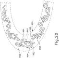
- FIGS. 19-20 show two annular arrays of staples (980, 990) that have been formed using anvil (900). As shown, crowns (982) are all substantially aligned along the inner circumferential line (C L ); while crowns (992) are all substantially aligned along the outer circumferential line (C L ). FIGS. 19-20 also show how legs (984, 994) are outwardly deflected relative to corresponding circumferential lines (C L ); and how legs (986, 996) are inwardly deflected relative to corresponding circumferential lines (C L ).
- formed staples (980, 990) are substantially three-dimensional-extending along a circumferential dimension (i.e., along circumferential line (C L )), extending along a longitudinal dimension (i.e., into and out of the page in the view of FIG. 19 ), and extending along a radial dimension.
- FIG. 21 shows an exemplary alternative deck member (1000), while FIG. 22 shows an exemplary alternative anvil (1100) that may be used with deck member (1000).
- Deck member (1000) and anvil (1100) may both be used with a modified version of instrument (10). It should be understood that deck member (1000) may be readily incorporated into stapling head assembly (300) in place of deck member (320).
- Deck member (1000) of this example is configured and operable just like deck member (320), except for the differences described below.
- Deck member (1000) of the present example comprises a deck surface (1006) defining an inner annular array of staple openings (1002) and an outer annular array of staple openings (1004).
- a staple (1080) is positioned in each inner staple opening (1002) while a staple (1090) is positioned in each outer staple opening (1004).
- a staple driver member (not shown), which may be configured and operable similar to staple driver member (350) described above, may be positioned under staples (1080, 1090) and may thereby drive staples (1080, 1090) out through openings (1002, 1004).
- Openings (1002) are configured and arranged such that openings (1002) are oriented obliquely relative to circumferential line (C L ).
- openings (1002) are configured and arranged such that circumferential line (C L ) will pass through the center of each crown (1082) of each staple (1080); such that first leg (1084) of each staple (1080) is positioned radially inwardly relative to circumferential line (C L ); and such that second leg (1086) of each staple (1080) is positioned radially outwardly relative to circumferential line (C L ).
- openings (1004) are configured and arranged such that openings (1004) are oriented obliquely relative to circumferential line (C L ).
- openings (1004) are configured and arranged such that circumferential line (C L ) will pass through the center of each crown (1092) of each staple (1090); such that first leg (1094) of each staple (1090) is positioned radially outwardly relative to circumferential line (C L ); and such that second leg (1096) of each staple (1090) is positioned radially inwardly relative to circumferential line (C L ).
- Anvil (1100) of this example is configured and operable just like anvil (400), except for the differences described below.
- Anvil (1100) of the present example comprises a proximal surface (1106) that defines an inner annular array (1102) of staple forming pockets (1110, 1130) and an outer annular array (1104) of staple forming pockets (1150, 1170).
- a chamfered edge extends about the outer perimeter of proximal surface (106).
- anvil (1100) may be secured to trocar (330), that proximal surface (106) may be used to compress tissue against deck surface (1006), and that a staple driver (not shown) may drive staples (1080, 1090) through tissue into staple forming pockets (1110, 1130, 1150, 1170) in order to thereby form staples (1080, 1090) in the tissue.
- each staple forming pocket (1110, 1130, 1150, 170) is configured identically to each other.
- each staple forming pocket (1110, 1130, 1150, 1170) has a generally rectangular shape at proximal surface (1106), such that staple forming pockets (1110, 1130, 1150, 1170) are not tapered along proximal surface (1106).
- the sidewalls of staple forming pockets (1110, 1130, 1150, 1170) slope toward each other as the sidewalls approach the floors of staple forming pockets (1110, 1130, 1150, 1170).
- the floors of staple forming pockets (1110, 1130, 1150, 1170) are concave, such that a staple leg (1084, 1086, 1094, 1096) will first encounter a corresponding staple entry point, then bend generally toward the other leg of staple (1080, 1090) along a first plane that is orthogonal to the axis of the unformed first leg, and then bend proximally back generally toward the crown (1082, 1092) of staple (1080, 1090).
- each pair of staple forming pockets (1110, 1130) is centered along a corresponding circumferential line (C L ), and each pair of staple forming pockets (1150,1170) is also centered along a corresponding circumferential line (C L ).
- an inner circumferential line (C L ) passes through the center and opposing corners of each pair of staple forming pockets (1110, 1130); while an outer circumferential line (C L ) passes through the center and opposing corners of each pair of staple forming pockets (1150, 1170).
- each pair of staple forming pockets (1110, 1130, 1150, 1170) is oriented obliquely relative to the corresponding circumferential line (C L ).
- each staple forming pocket (1110) is angularly aligned with the other staple forming pocket (1130) in the pair of pockets (1110, 1130); and each staple forming pocket (1150) is angularly aligned with the other staple forming pocket (1170) in the pair of pockets (1150, 1170).
- inner array (1102) and outer array (1104) are arranged to provide mirrored symmetry, such that the pocket (1110) in each pair of inner pockets (1110, 1130) providing the outer-most formed leg (1086) is on the bottom (in the view of FIG. 22 ) of the pair of pockets (1110, 1130); and such that pocket (1170) in each pair of outer pockets (1150, 1170) providing the inner-most formed leg (1096) is on the bottom (in the view of FIG. 22 ) of the pair of pockets (1150, 1170).
- the pocket (1130) in each pair of inner pockets (1110, 1130) providing the inner-most formed leg (1084) is on the top (in the view of FIG.
- the symmetry between arrays (1102, 1104) is opposite of the symmetry between arrays (502, 504) described above. Instead, the symmetry between arrays (1102, 1104) is like the symmetry between arrays (702, 704) and the symmetry between arrays (902, 904).
- staple forming pockets (1110, 1130, 1150, 1170) are arranged such that a radius line (R L ) extending outwardly from the center of anvil (1100) passes between staple forming pockets (1150, 1170) such that staple forming pockets (1150, 1170) in each pair of staple forming pockets (1150, 1170) do not overlap each other along a radial dimension.
- another radius line (R L ) extending outwardly from the center of anvil (1100) passes between staple forming pockets (1110, 1130) such that staple forming pockets (1110, 1130) in each pair of staple forming pockets (1110, 1130) do not overlap each other along a radial dimension.
- FIG. 1 Another radius line (R L ) extending outwardly from the center of anvil (1100) passes through staple forming pocket (1130) and through staple forming pocket (1170).
- staple forming pockets (1130, 1170) overlap along a radial dimension. It should be understood that staple forming pockets (1110, 1150) have the same kind of overlap along a radial dimension.
- staples (1090, 1080) formed by anvil (1100) are only substantially two-dimensional-extending along dimension that is oblique relative to circumferential line (C L ) and extending along a longitudinal dimension (i.e., into and out of the page in the view of FIG. 22 ).
- This two-dimensional configuration of formed staples (1090, 1090) provides an appearance similar to the letter "B.”
- FIG. 22 While the view depicted in FIG. 22 only shows a portion of the full circumference of anvil (1100), it should be understood that the structures depicted in FIG. 22 extend along the full circumference of anvil (1100).
- the view of FIG. 22 is simply being provided as an enlargement to show the structure in further detail, and is not intended to suggest that the depicted structures are only located in a limited angular range along the circumference of anvil (1100).
- An apparatus comprising: (a) an anvil surface configured to compress tissue against a deck surface, wherein the anvil surface defines: (i) an inner annular array of staple forming pockets, wherein the inner annular array of staple forming pockets comprises a plurality of staple forming pocket pairs, wherein each pair of staple forming pockets in the inner annular array comprises: (A) a first staple forming pocket, and (B) a second staple forming pocket, and (ii) an outer annular array of staple forming pockets, wherein the outer annular array of staple forming pockets comprises a plurality of staple forming pocket pairs, wherein each pair of staple forming pockets in the outer annular array comprises: (A) a first staple forming pocket, and (B) a second staple forming pocket, wherein the outer annular array of staple forming pockets is arranged in a mirrored symmetry with the inner annular array of staple forming pockets; and (b) an anvil shaft extending along a longitudinal axis, wherein the anvil shaft is configured to couple with a
- Example 1 The apparatus of Example 1, wherein the first staple forming pocket of each pair of staple forming pockets of the inner annular array is located radially outboard of the second staple forming pocket of the same pair of staple forming pockets of the inner annular array.
- Example 2 wherein the second staple forming pocket of each pair of staple forming pockets of the outer annular array is located radially outboard of the first staple forming pocket of the same pair of staple forming pockets of the outer annular array.
- Example 3 wherein the first staple forming pocket of each pair of staple forming pockets of the inner annular array includes a bent or chamfered region, wherein the bent or chamfered region is configured to provide a minimum wall thickness between the first staple forming pocket of each pair of staple forming pockets of the inner annular array and a corresponding first staple forming pocket of each pair of staple forming pockets of the outer annular array.
- Example 4 wherein the first staple forming pocket of each pair of staple forming pockets of the inner annular array overlaps with a corresponding second staple forming pocket of each pair of staple forming pockets of the outer annular array along a radial dimension.
- Example 5 wherein the second staple forming pocket of each pair of staple forming pockets of the inner annular array overlaps with a corresponding first staple forming pocket of each pair of staple forming pockets of the outer annular array along a radial dimension.
- each staple forming pocket has a generally triangular shape defined in part by two generally flat sides that taper toward each other from a staple entry region toward a staple exit region.
- each staple forming pockets is configured to deform a staple along three dimensions.
- Example 10 wherein the three dimensions include a longitudinal dimension parallel to the longitudinal axis, a first orthogonal dimension extending orthogonally relative to the longitudinal axis, and a second orthogonal dimension extending orthogonally relative to the longitudinal axis.
- the first staple forming pockets of the inner annular array are configured to deform a staple leg radially outwardly relative to the longitudinal axis, wherein the second staple forming pockets of the inner annular array are configured to deform a staple leg radially inwardly relative to the longitudinal axis.
- each pair of staple forming pockets in the inner annular array is substantially centered along a circumferential line extending along the anvil surface at a constant radius from the longitudinal axis.
- each first staple forming pocket of the inner annular array is substantially centered along a circumferential line extending along the anvil surface at a constant radius from the longitudinal axis, wherein each second staple forming pocket of the inner annular array is oriented obliquely relative to the same circumferential line extending along the anvil surface at a constant radius from the longitudinal axis.
- each first staple forming pocket of the inner annular array comprises a staple entry region and a staple exit region, wherein the staple entry region is wider than the staple exit region.
- each first staple forming pocket of the inner annular array further comprises a fourth sidewall providing an angled transition from the second sidewall to the third sidewall.
- the stapling head assembly comprises: (i) a deck surface, wherein the deck surface is configured to cooperate with the anvil surface to compress tissue, (ii)
- An apparatus comprising: (a) an anvil surface configured to compress tissue against a deck surface, wherein the anvil surface defines: (i) an inner annular array of staple forming pockets, wherein the inner annular array of staple forming pockets comprises a plurality of staple forming pocket pairs, wherein each pair of staple forming pockets in the inner annular array comprises: (A) a first staple forming pocket, and (B) a second staple forming pocket, wherein the first staple forming pocket of each pair of staple forming pockets of the inner annular array is located radially outboard of the second staple forming pocket of the same pair of staple forming pockets of the inner annular array, and (ii) an outer annular array of staple forming pockets, wherein the outer annular array of staple forming pockets comprises a plurality of staple forming pocket pairs, wherein each pair of staple forming pockets in the outer annular array comprises: (A) a first staple forming pocket, and (B) a second staple forming pocket, wherein the second staple forming pocket of each pair of staple
- An apparatus comprising: (a) a shaft assembly; (b) a stapling head assembly located at a distal end of the shaft assembly, wherein the stapling head assembly comprises: (i) a deck surface, (ii) a first annular array of staple openings formed through the deck surface, (iii) a second annular array of staple openings formed through the deck surface, and (iv) a plurality of staples associated with the first and second annular arrays of staple openings, wherein the stapling head assembly is operable to drive the staples through the first and second annular arrays of staple openings; and (c) an anvil, wherein the anvil comprises: (i) an anvil surface configured to compress tissue against the deck surface, (ii) a first annular array of staple forming pockets formed in the anvil surface, wherein the first annular array of staple forming pockets comprises a plurality of pairs of staple forming pockets, and (iii) a second annular array of staple forming pockets formed in the anvil
- Versions of the devices described above may have application in conventional medical treatments and procedures conducted by a medical professional, as well as application in robotic-assisted medical treatments and procedures.
- various teachings herein may be readily incorporated into a robotic surgical system such as the DAVINCITM system by Intuitive Surgical, Inc., of Sunnyvale, California.
- Versions described above may be designed to be disposed of after a single use, or they can be designed to be used multiple times. Versions may, in either or both cases, be reconditioned for reuse after at least one use. Reconditioning may include any combination of the steps of disassembly of the device, followed by cleaning or replacement of particular pieces, and subsequent reassembly. In particular, some versions of the device may be disassembled, and any number of the particular pieces or parts of the device may be selectively replaced or removed in any combination. Upon cleaning and/or replacement of particular parts, some versions of the device may be reassembled for subsequent use either at a reconditioning facility, or by a user immediately prior to a procedure.
- reconditioning of a device may utilize a variety of techniques for disassembly, cleaning/replacement, and reassembly. Use of such techniques, and the resulting reconditioned device, are all within the scope of the present application.
- versions described herein may be sterilized before and/or after a procedure.
- the device is placed in a closed and sealed container, such as a plastic or TYVEK bag.
- the container and device may then be placed in a field of radiation that can penetrate the container, such as gamma radiation, x-rays, or high-energy electrons.
- the radiation may kill bacteria on the device and in the container.
- the sterilized device may then be stored in the sterile container for later use.
- a device may also be sterilized using any other technique known in the art, including but not limited to beta or gamma radiation, ethylene oxide, or steam.
Landscapes
- Health & Medical Sciences (AREA)
- Life Sciences & Earth Sciences (AREA)
- Surgery (AREA)
- Heart & Thoracic Surgery (AREA)
- Engineering & Computer Science (AREA)
- Biomedical Technology (AREA)
- Nuclear Medicine, Radiotherapy & Molecular Imaging (AREA)
- Medical Informatics (AREA)
- Molecular Biology (AREA)
- Animal Behavior & Ethology (AREA)
- General Health & Medical Sciences (AREA)
- Public Health (AREA)
- Veterinary Medicine (AREA)
- Surgical Instruments (AREA)
Abstract
Description
- In some surgical procedures (e.g., colorectal, bariatric, thoracic, etc.), portions of a patient's digestive tract (e.g., the gastrointestinal tract and/or esophagus, etc.) may be cut and removed to eliminate undesirable tissue or for other reasons. Once the tissue is removed, the remaining portions of the digestive tract may be coupled together in an end-to-end anastomosis. The end-to-end anastomosis may provide a substantially unobstructed flow path from one portion of the digestive tract to the other portion of the digestive tract, without also providing any kind of leaking at the site of the anastomosis.
- One example of an instrument that may be used to provide an end-to-end anastomosis is a circular stapler. Some such staplers are operable to clamp down on layers of tissue, cut through the clamped layers of tissue, and drive staples through the clamped layers of tissue to substantially seal the layers of tissue together near the severed ends of the tissue layers, thereby joining the two severed ends of the anatomical lumen together. The circular stapler may be configured to sever the tissue and seal the tissue substantially simultaneously. For instance, the circular stapler may sever excess tissue that is interior to an annular array of staples at an anastomosis, to provide a substantially smooth transition between the anatomical lumen sections that are joined at the anastomosis. Circular staplers may be used in open procedures or in endoscopic procedures. In some instances, a portion of the circular stapler is inserted through a patient's naturally occurring orifice.
- Examples of circular staplers are described in
U.S. Pat. No. 5,205,459 , entitled "Surgical Anastomosis Stapling Instrument," issued April 27, 1993;U.S. Pat. No. 5,271,544 , entitled "Surgical Anastomosis Stapling Instrument," issued December 21, 1993;U.S. Pat. No. 5,275,322 , entitled "Surgical Anastomosis Stapling Instrument," issued January 4, 1994;U.S. Pat. No. 5,285,945 , entitled "Surgical Anastomosis Stapling Instrument," issued February 15, 1994;U.S. Pat. No. 5,292,053 , entitled "Surgical Anastomosis Stapling Instrument," issued March 8, 1994;U.S. Pat. No. 5,333,773 , entitled "Surgical Anastomosis Stapling Instrument," issued August 2, 1994;U.S. Pat. No. 5,350,104 , entitled "Surgical Anastomosis Stapling Instrument," issued September 27, 1994; andU.S. Pat. No. 5,533,661 , entitled "Surgical Anastomosis Stapling Instrument," issued July 9, 1996; andU.S. Pat. No. 8,910,847 , entitled "Low Cost Anvil Assembly for a Circular Stapler," issued December 16, 2014. The disclosure of each of the above-cited U.S. Patents is incorporated by reference herein. - Some circular staplers may include a motorized actuation mechanism. Examples of circular staplers with motorized actuation mechanisms are described in
U.S. Pub. No. 2015/0083772 , entitled "Surgical Stapler with Rotary Cam Drive and Return," published March 26, 2015;U.S. Pub. No. 2015/0083773 , entitled "Surgical Stapling Instrument with Drive Assembly Having Toggle Features," published March 26, 2015;U.S. Pub. No. 2015/0083774 , entitled "Control Features for Motorized Surgical Stapling Instrument," published March 26, 2015; andU.S. Pub. No. 2015/0083775 , entitled "Surgical Stapler with Rotary Cam Drive," published March 26, 2015. The disclosure of each of the above-cited U.S. Patent Publications is incorporated by reference herein. - While various kinds of surgical stapling instruments and associated components have been made and used, it is believed that no one prior to the inventor(s) has made or used the invention described in the appended claims.
- While the specification concludes with claims which particularly point out and distinctly claim this technology, it is believed this technology will be better understood from the following description of certain examples taken in conjunction with the accompanying drawings, in which like reference numerals identify the same elements and in which:
-
FIG. 1 depicts a perspective view of an exemplary circular stapler; -
FIG. 2 depicts a perspective view of the circular stapler ofFIG. 1 , with a battery pack removed from a handle assembly and an anvil removed from a stapling head assembly; -
FIG. 3 depicts a perspective view of the anvil of the circular stapler ofFIG. 1 ; -
FIG. 4 depicts a perspective view of the stapling head assembly of the circular stapler ofFIG. 1 ; -
FIG. 5 depicts an exploded perspective view of the stapling head assembly ofFIG. 4 ; -
FIG. 6 depicts an exploded perspective view of the circular stapler ofFIG. 1 , with portions of the shaft assembly shown separately from each other; -
FIG. 7A depicts a cross-sectional side view of the anvil ofFIG. 3 positioned within a first section of a digestive tract and the stapling head assembly ofFIG. 4 positioned in a second section of the digestive tract, with the anvil separated from the stapling head assembly; -
FIG. 7B depicts a cross-sectional side view of the anvil ofFIG. 3 positioned within the first section of the digestive tract and the stapling head assembly ofFIG. 4 positioned in the second section of the digestive tract, with the anvil secured to the stapling head assembly; -
FIG. 7C depicts a cross-sectional side view of the anvil ofFIG. 3 positioned within the first section of the digestive tract and the stapling head assembly ofFIG. 4 positioned in the second section of the digestive tract, with the anvil retracted toward the stapling head assembly to thereby clamp tissue between the anvil and the stapling head assembly; -
FIG. 7D depicts a cross-sectional side view of the anvil ofFIG. 3 positioned within the first section of the digestive tract and the stapling head assembly ofFIG. 4 positioned in the second section of the digestive tract, with the stapling head assembly actuated to sever and staple the clamped tissue; -
FIG. 7E depicts a cross-sectional side view of the first and second sections of the digestive tract ofFIG. 7A joined together at an end-to-end anastomosis; -
FIG. 8 depicts a bottom plan view of an exemplary alternative anvil that may be used with the circular stapler ofFIG. 1 ; -
FIG. 9 depicts an enlarged bottom plan view of a portion of the anvil ofFIG. 8 ; -
FIG. 10 depicts an enlarged perspective view of a portion of the anvil ofFIG. 8 ; -
FIG. 11 depicts an enlarged bottom plan view of a portion of an exemplary alternative anvil that may be used with the circular stapler ofFIG. 1 ; -
FIG. 12 depicts a bottom plan view of another exemplary alternative anvil that may be used with the circular stapler ofFIG. 1 ; -
FIG. 13 depicts an enlarged bottom plan view of a portion of the anvil ofFIG. 12 ; -
FIG. 14 depicts an enlarged perspective view of a portion of the anvil ofFIG. 12 ; -
FIG. 15 depicts an enlarged bottom plan view of another exemplary alternative anvil that may be used with the circular stapler ofFIG. 1 ; -
FIG. 16 depicts an enlarged top plan view of a portion of an array of staples formed using the anvil ofFIG. 15 ; -
FIG. 17 depicts an enlarged perspective view of a portion of an array of staples formed using the anvil ofFIG. 15 ; -
FIG. 18 depicts an enlarged bottom plan view of another exemplary alternative anvil that may be used with the circular stapler ofFIG. 1 ; -
FIG. 19 depicts an enlarged top plan view of a portion of an array of staples formed using the anvil ofFIG. 18 ; -
FIG. 20 depicts an enlarged perspective view of a portion of an array of staples formed using the anvil ofFIG. 18 ; -
FIG. 21 depicts a top plan view of a portion of an exemplary alternative stapling head assembly that may be incorporated into the circular stapler ofFIG. 1 ; and -
FIG. 22 depicts a bottom plan view of a portion of an exemplary alternative anvil that may be used in conjunction with the stapling head assembly ofFIG. 21 . - The drawings are not intended to be limiting in any way, and it is contemplated that various embodiments of the technology may be carried out in a variety of other ways, including those not necessarily depicted in the drawings. The accompanying drawings incorporated in and forming a part of the specification illustrate several aspects of the present technology, and together with the description serve to explain the principles of the technology; it being understood, however, that this technology is not limited to the precise arrangements shown.
- The following description of certain examples of the technology should not be used to limit its scope. Other examples, features, aspects, embodiments, and advantages of the technology will become apparent to those skilled in the art from the following description, which is by way of illustration, one of the best modes contemplated for carrying out the technology. As will be realized, the technology described herein is capable of other different and obvious aspects, all without departing from the technology. Accordingly, the drawings and descriptions should be regarded as illustrative in nature and not restrictive.
-
FIGS. 1-2 depict an exemplary surgical circular stapling instrument (10) that may be used to provide an end-to-end anastomosis between two sections of an anatomical lumen such as a portion of a patient's digestive tract. Instrument (10) of this example comprises a handle assembly (100), a shaft assembly (200), a stapling head assembly (300), an anvil (400), and a removable battery pack (120). Each of these components will be described in greater detail below. It should be understood that, in addition to or in lieu of the following, instrument (10) may be further constructed and operable in accordance with at least some of the teachings ofU.S. Pat. App. No. 14/751,612 U.S. Pat. No. 5,205,459 ;U.S. Pat. No. 5,271,544 ;U.S. Pat. No. 5,275,322 ;U.S. Pat. No. 5,285,945 ;U.S. Pat. No. 5,292,053 ;U.S. Pat. No. 5,333,773 ;U.S. Pat. No. 5,350,104 ;U.S. Pat. No. 5,533,661 ; and/orU.S. Pat. No. 8,910,847 , the disclosures of which are incorporated by reference herein. Still other suitable configurations will be apparent to one of ordinary skill in the art in view of the teachings herein. - As best seen in
FIG. 3 , anvil (400) of the present example comprises a head (410) and a shank (420). Head (410) includes a proximal surface (412) that defines a plurality of staple forming pockets (414). Staple forming pockets (414) are arranged in two concentric annular arrays in the present example. Staple forming pockets (414) are configured to deform staples as the staples are driven into staple forming pockets (414) (e.g., deforming a generally "U" shaped staple into a "B" shape as is known in the art). Shank (420) defines a bore or lumen (422) and includes a pair of pivoting latch members (430) positioned in bore (422). Each latch member (430) includes features that allows anvil (400) to be removably secured to a trocar (330) of stapling head assembly (300) as will be described in greater detail below. It should be understood, however, that anvil (400) may be removably secured to a trocar (330) using any other suitable components, features, or techniques. - Stapling head assembly (300) is located at the distal end of shaft assembly (200). As shown in
FIGS. 1-2 , anvil (400) is configured to removably couple with shaft assembly (200), adjacent to stapling head assembly (300). As will be described in greater detail below, anvil (400) and stapling head assembly (300) are configured to cooperate to manipulate tissue in three ways, including clamping the tissue, cutting the tissue, and stapling the tissue. As best seen inFIGS. 4-5 , stapling head assembly (300) of the present example comprises a tubular casing (310) housing a slidable staple driver member (350). A cylindraceous inner core member (312) extends distally within tubular casing (310). Tubular casing (310) is fixedly secured to an outer sheath (210) of shaft assembly (200), such that tubular casing (310) serves as a mechanical ground for stapling head assembly (300). - Trocar (330) is positioned coaxially within inner core member (312) of tubular casing (310). Trocar (330) is operable to translate distally and proximally relative to tubular casing (310) in response to rotation of a knob (130) located at the proximal end of handle assembly (100). Trocar (330) comprises a shaft (332) and ahead (334). Head (334) includes a pointed tip (336) and an inwardly extending proximal surface (338). Head (334) and the distal portion of shaft (332) are configured for insertion in bore (422) of anvil (420). Proximal surface (338) is configured to complement features of latch members (430) to provide a snap fit between anvil (400) and trocar (330).
- Staple driver member (350) is operable to actuate longitudinally within tubular casing (310) in response to activation of motor (160) as will be described in greater detail below. Staple driver member (350) includes two distally presented concentric annular arrays of staple drivers (352). Staple drivers (352) are arranged to correspond with the arrangement of staple forming pockets (414) described above. Thus, each staple driver (352) is configured to drive a corresponding staple into a corresponding staple forming pocket (414) when stapling head assembly (300) is actuated. Staple driver member (350) also defines a bore (354) that is configured to coaxially receive core member (312) of tubular casing (310).
- A cylindraceous knife member (340) is coaxially positioned within staple driver member (350). Knife member (340) includes a distally presented, sharp circular cutting edge (342). Knife member (340) is sized such that knife member (340) defines an outer diameter that is smaller than the diameter defined by the inner annular array of staple drivers (352). Knife member (340) also defines an opening that is configured to coaxially receive core member (312) of tubular casing (310).
- A deck member (320) is fixedly secured to tubular casing (310). Deck member (320) includes a distally presented deck surface (322) defining two concentric annular arrays of staple openings (324). Staple openings (324) are arranged to correspond with the arrangement of staple drivers (352) and staple forming pockets (414) described above. Thus, each staple opening (324) is configured to provide a path for a corresponding staple driver (352) to drive a corresponding staple through deck member (320) and into a corresponding staple forming pocket (414) when stapling head assembly (300) is actuated. It should be understood that the arrangement of staple openings (322) may be modified just like the arrangement of staple forming pockets (414) as described above. It should also be understood that various structures and techniques may be used to contain staples within stapling head assembly (300) before stapling head assembly (300) is actuated. Deck member (320) defines an inner diameter that is just slightly larger than the outer diameter defined by knife member (340). Deck member (320) is thus configured to allow knife member (340) to translate distally to a point where cutting edge (342) is distal to deck surface (322).
-
FIG. 6 shows various components of shaft assembly (200), which extends distally from handle assembly (100) and couples components of stapling head assembly (300) with components of handle assembly (100). In particular, and as noted above, shaft assembly (200) includes an outer sheath (210) that extends between handle assembly (100) and tubular casing (310). In the present example, outer sheath (210) is rigid and includes a preformed curved section (212) that is configured to facilitate positioning of stapling head assembly (300) within a patient's colon as described below. Curved section (212) includes an inner curve (216) and an outer curve (214). - Shaft assembly (200) further includes a trocar actuation rod (220) and a trocar actuation band assembly (230). The distal end of trocar actuation band assembly (230) is fixedly secured to the proximal end of trocar shaft (332). The proximal end of trocar actuation band assembly (230) is fixedly secured to the distal end of trocar actuation rod (220), such that trocar (330) will translate longitudinally relative to outer sheath (210) in response to translation of trocar actuation band assembly (230) and trocar actuation rod (220) relative to outer sheath (210). Trocar actuation band assembly (230) is configured to flex such that trocar actuation band assembly (230) may follow along the preformed curve in shaft assembly (200) as trocar actuation band assembly (230) is translated longitudinally relative to outer sheath (210). However, trocar actuation band assembly (230) has sufficient column strength and tensile strength to transfer distal and proximal forces from trocar actuation rod (220) to trocar shaft (332). Trocar actuation rod (220) is rigid. A clip (222) is fixedly secured to trocar actuation rod (220) and is configured to cooperate with complementary features within handle assembly (100) to prevent trocar actuation rod (220) from rotating within handle assembly (100) while still permitting trocar actuation rod (220) to translate longitudinally within handle assembly (100). Trocar actuation rod (220) further includes a coarse helical threading (224) and a fine helical threading (226).
- Shaft assembly (200) further includes a stapling head assembly driver (240) that is slidably received within outer sheath (210). The distal end of stapling head assembly driver (240) is fixedly secured to the proximal end of staple driver member (350). The proximal end of stapling head assembly driver (240) is secured to a drive bracket (250) via a pin (242). It should therefore be understood that staple driver member (350) will translate longitudinally relative to outer sheath (210) in response to translation of stapling head assembly driver (240) and drive bracket (250) relative to outer sheath (210). Stapling head assembly driver (240) is configured to flex such that stapling head assembly driver (240) may follow along the preformed curve in shaft assembly (200) as stapling head assembly driver (240) is translated longitudinally relative to outer sheath (210). However, stapling head assembly driver (240) has sufficient column strength to transfer distal forces from drive bracket (250) to staple driver member (350).
- As shown in
FIG. 1 , handle assembly (100) includes a pistol grip (112) and several components that are operable to actuate anvil (400) and stapling head assembly (300). In particular, handle assembly (100) includes knob (130), a safety trigger (140) a firing trigger (150), a motor (160), and a motor activation module (180). Knob (130) is coupled with trocar actuation rod (220) via a nut (not shown), such that coarse helical threading (224) will selectively engage a thread engagement feature within the interior of the nut; and such that fine helical threading (226) will selectively engage a thread engagement feature within the interior of knob (130). These complementary structures are configured such that trocar actuation rod (220) will first translate proximally at a relatively slow rate, then translate proximally at a relatively fast rate, in response to rotation of knob (130). - It should be understood that when anvil (400) is coupled with trocar (330), rotation of knob (130) will provide corresponding translation of anvil relative to stapling head assembly (300). It should also be understood that knob (130) may be rotated in a first angular direction (e.g., clockwise) to retract anvil (400) toward stapling head assembly (300); and in a second angular direction (e.g., counterclockwise) to advance anvil (500) away from stapling head assembly (300). Knob (130) may thus be used to adjust the gap distance between opposing surfaces (412, 322) of anvil (400) and stapling head assembly (300) until a suitable gap distance has been achieved.
- In the present example, handle assembly (100) comprises a user feedback feature (114) that is configured to provide the operator with visual feedback indicating the positioning of anvil (400) in relation to stapling assembly (300). The operator may thus observe user feedback feature (114) while rotating knob (130), to confirm whether the suitable gap distance between anvil (400) and stapling assembly (300) has been achieved. By way of example only, user feedback feature (114) may be configured and operable in accordance with at least some of the teachings of
U.S. Pat. App. No. 14/751,612 - Firing trigger (150) is operable to activate motor (160) to thereby actuate stapling head assembly (300). Safety trigger (140) is operable to selectively block actuation of firing trigger (150) based on the longitudinal position of anvil (400) in relation to stapling head assembly (300). Handle assembly (100) also includes components that are operable to selectively lock out both triggers (140, 150) based on the position of anvil (400) relative to stapling head assembly (300). When triggers (140, 150) are locked out, firing trigger (150) is prevented from initiating actuation of stapling head assembly (300). Thus, trigger (150) is only operable to initiate actuation of stapling head assembly (300) when the position of anvil (400) relative to stapling head assembly (300) is within a predefined range.
- In the present example, firing trigger (150) of the present example includes an integral actuation paddle, such as the paddle shown and described in
U.S. Patent App. No. 14/751,231 FIG. 1 ) when firing trigger (150) is pivoted to a fired position. Motor activation module (180) is in communication with battery pack (120) and motor (160), such that motor activation module (180) is configured to provide activation of motor (160) with electrical power from battery pack (120) in response to the paddle actuating the switch of motor activation module (180). Thus, motor (160) will be activated when firing trigger (150) is pivoted. This activation of motor (160) will actuate stapling head assembly (300) as described in greater detail below. - Battery pack (120) is operable to provide electrical power to a motor (160) as noted above. Battery pack (120) may be removably coupled with handle assembly (100) through a snap fit or in any other suitable fashion. It should be understood that battery pack (120) and handle assembly (100) may have complementary electrical contacts, pins and sockets, and/or other features that provide paths for electrical communication from battery pack (120) to electrically powered components in handle assembly (100) when battery pack (120) is coupled with handle assembly (100). It should also be understood that, in some versions, battery pack (120) is unitarily incorporated within handle assembly (100) such that battery back (120) cannot be removed from handle assembly (100).
-
FIGS. 7A-7E show instrument (10) being used to form an anastomosis (70) between two tubular anatomical structures (20, 40). By way of example only, the tubular anatomical structures (20, 40) may comprise sections of a patient's esophagus, sections of a patient's colon, other sections of the patient's digestive tract, or any other tubular anatomical structures. In some versions, one or more diseased portions of a patient's colon are removed, with the tubular anatomical structures (20, 40) ofFIGS. 7A-7E representing the remaining severed portions of the colon. - As shown in
FIG. 7A , anvil (400) is positioned in one tubular anatomical structure (20) and stapling head assembly (300) is positioned in another tubular anatomical structure (40). In versions where tubular anatomical structures (20, 40) comprise sections of a patient's colon, stapling head assembly (300) may be inserted via the patient's rectum. It should also be understood that the procedure depicted inFIGS. 7A-7E is an open surgical procedure, though the procedure may instead be performed laparoscopically. By way of example only, the surgical procedure may be performed laparoscopically in accordance with at least some of the teachings ofU.S. Pub. No. 2016/0100837 , entitled "Staple Cartridge," published April 14, 2016, the disclosure of which is incorporated by reference herein; and/orU.S. Pat. App. No. 14/864,310 - As shown in
FIG. 7A , anvil (400) is positioned in tubular anatomical structure (20) such that shank (420) protrudes from the open severed end (22) of tubular anatomical structure (20). A purse-string suture (30) is provided about a mid-region of shank (420) to generally secure the position of anvil (400) in tubular anatomical structure (20). Similarly, stapling head assembly (300) is positioned in tubular anatomical structure (40) such that trocar (330) protrudes from the open severed end (42) of tubular anatomical structure (20). A purse-string suture (50) is provided about a mid-region of shaft (332) to generally secure the position of stapling head assembly (300) in tubular anatomical structure (40). - Next, anvil (400) is secured to trocar (330) by inserting trocar (330) into bore (422) as shown in
FIG. 7B . Latch members (430) engage head (334) of trocar (330), thereby providing a secure fit between anvil (400) and trocar (330). The operator then rotates knob (130) while holding handle assembly (100) stationary via pistol grip (112). This rotation of knob (130) causes trocar (330) and anvil (400) to retract proximally, as described above. As shown inFIG. 7C , this proximal retraction of trocar (330) and anvil (400) compresses the tissue of tubular anatomical structures (20, 40) between surfaces (412, 322) of anvil (400) and stapling head assembly (300). The operator observes user feedback feature (114) to determine whether the gap distance (d) between opposing surfaces (412, 322) of anvil (400) and stapling head assembly (300) is appropriate; and makes any necessary adjustments via knob (130). - Once the operator has appropriately set the gap distance (d) via knob (130), the operator actuates safety trigger (140) to enable actuation of firing trigger (150). The operator then actuates firing trigger (150). This actuation of firing trigger (150) in turn actuates a switch of motor activation module (180), which in turn activates motor (160) to thereby actuate stapling head assembly (300) by driving knife member (340) and staple driver member (350) distally as shown in
FIG. 7D . As knife member (340) translates distally, cutting edge (342) of knife member (340) cooperates with inner edge (416) of anvil (400), thereby shearing excess tissue that is positioned within annular recess (418) of anvil (400) and the interior of knife member (340). - As shown in
FIG. 4 , anvil (400) of the present example includes a breakable washer (417) within annular recess (418). This washer (417) is broken by knife member (340) when knife member (340) completes a full distal range of motion from the position shown inFIG. 7C to the position shown inFIG. 7D . The drive mechanism for knife member (340) may provide an increasing mechanical advantage as knife member (340) reaches the end of its distal movement, thereby providing greater force by which to break washer (417). Of course, breakable washer (417) may be omitted entirely in some versions. In versions where washer (417) is included, it should be understood that washer (417) may also serve as a cutting board for knife member (340) to assist in cutting of tissue. Such a cutting technique may be employed in addition to or in lieu of the above-noted shearing action between inner edge (416) and cutting edge (342). - As staple driver member (350) translates distally from the position shown in
FIG. 7C to the position shown inFIG. 7D , staple driver member (350) drives staples (90) through the tissue of tubular anatomical structures (20, 40) and into staple forming pockets (414) of anvil (400). Staple forming pockets (414) deform the driven staples (90) into a "B" shape as is known in the art. The formed staples (90) thus secure the ends of tissue together, thereby coupling tubular anatomical structure (20) with tubular anatomical structure (40). - After the operator has actuated stapling head assembly (300) as shown in
FIG. 7D , the operator rotates knob (130) to drive anvil (400) distally away from stapling head assembly (300), increasing the gap distance (d) to facilitate release of the tissue between surfaces (412, 322). The operator then removes instrument (10) from the patient, with anvil (400) still secured to trocar (330). Referring back to the example where the tubular anatomical structures (20, 40) comprise sections of a patient's colon, instrument (10) may be removed via the patient's rectum. With instrument (10) removed, the tubular anatomical structures (20, 40) are left secured together by two annular arrays of staples (90) at an anastomosis (70) as shown inFIG. 7E . The inner diameter of the anastomosis (70) is defined by the severed edge (60) left by knife member (340). - In some instances, it may be desirable to change the configuration and arrangement of staple forming pockets (414) in anvil (400). It should be understood that reconfiguring and rearranging staple forming pockets (414) may result in reconfiguration and rearrangement of staples (90) that are formed by staple forming pockets (414). For instance, the configuration and arrangement of staple forming pockets (414) may affect the structural integrity of an anastomosis (70) that is secured by staples (90). In addition, the configuration and arrangement of staple forming pockets (414) may affect the hemostasis that is achieved at an anastomosis (70) that is secured by staples (90). The following description relates to several exemplary variations of anvil (400), providing staple forming pocket configurations and arrangements that differ from those of staple forming pockets (414).
- It should be understood that the various alternatives to anvil (400) described below may be readily used with instrument (10), in place of anvil (400). It should also be understood that, in some instances, the configuration and arrangement of staple openings (324) in deck member (320) may need to be varied in order to complement the configuration and arrangement of the alternative staple forming pockets described below. Various suitable ways in which the alternatives to anvil (400) described below may be incorporated into instrument (10) will be apparent to those of ordinary skill in the art in view of the teachings herein.
-
FIGS. 8-10 show an exemplary alternative anvil (500) that may be used with a modified version of instrument (10). Anvil (500) of this example is configured and operable just like anvil (400), except for the differences described below. Anvil (500) of the present example comprises a proximal surface (506) that defines an inner annular array (502) of staple forming pockets (510, 530) and an outer annular array (504) of staple forming pockets (550, 570). A chamfered edge (508) extends about the outer perimeter of proximal surface (506). It should be understood that anvil (500) may be secured to trocar (330), that proximal surface (506) may be used to compress tissue against deck surface (322), and that staple driver (352) may drive staples (90) through tissue into staple forming pockets (510, 530, 550, 570) in order to thereby form staples (90) in the tissue. - As best seen in
FIGS. 9-10 , each staple forming pocket (510) comprises a staple entry surface (512) and a staple exit surface (514). Surfaces (512, 514) are contiguous with each other and define a concave recess. The concave recess formed by surfaces (512, 514) is further defined by an inner wall (516), a first outer wall (518), a second outer wall (520), and a third outer wall (522). In the present example, walls (516, 518, 520, 522) are each substantially flat. Wall (518) defines a relatively narrow, tapered gap with wall (516). Wall (522) defines a relatively wide gap with wall (516). Wall (520) is obliquely angled, providing an inwardly sloped transition from wall (522) to wall (518). Thus, walls (518, 520, 522) together provide a dogleg configuration. The edge connecting wall (516) with wall (522) is substantially straight in this example. Similarly, the edge connecting wall (516) with wall (518) is substantially straight in this example. - It should be understood that when a first leg of staple (90) is driven into staple forming pocket (510), the first leg first encounters staple entry surface (512), bends generally toward the second leg of staple (90) along a first plane that is orthogonal to the axis of the unformed first leg, and then bends proximally back generally toward the crown of staple (90). In addition, the first leg will eventually encounter wall (520), which will provide a cam surface bending the first leg along a second plane that is orthogonal to the axis of the unformed first leg. In particular, wall (520) and then wall (518) will deflect the first leg radially inwardly toward the central axis of anvil (500). Thus, staple forming pocket (510) will ultimately deflect a first leg of a staple (90) proximally and radially inwardly. Wall (516) will restrict the degree to which the first leg of staple (90) deflects radially inwardly.
- Each staple forming pocket (530) comprises a staple entry surface (532) and a staple exit surface (534). Surfaces (532, 534) are contiguous with each other and define a concave recess. The concave recess formed by surfaces (532, 534) is further defined by an outer wall (536), a first inner wall (538), a second inner wall (540), and a third inner wall (542). In the present example, walls (536, 538, 540, 542) are each substantially flat. Wall (538) defines a relatively narrow, tapered gap with wall (536). Wall (542) defines a relatively wide gap with wall (536). Wall (540) is obliquely angled, providing an outwardly sloped transition from wall (542) to wall (538). Thus, walls (538, 540, 542) together provide a dogleg configuration. The edge connecting wall (536) with wall (542) is substantially straight in this example. Similarly, the edge connecting wall (536) with wall (538) is substantially straight in this example.
- It should be understood that when a second leg of staple (90) is driven into staple forming pocket (530), the second leg first encounters staple entry surface (532), bends generally toward the first leg of staple (90) along a first plane that is orthogonal to the axis of the unformed second leg, and then bends proximally back generally toward the crown of staple (90). In addition, the second leg will eventually encounter wall (540), which will provide a cam surface bending the second leg along a second plane that is orthogonal to the axis of the unformed second leg. In particular, wall (540) and then wall (538) will deflect the second leg radially outwardly away from the central axis of anvil (500). Thus, staple forming pocket (530) will ultimately deflect a second leg of a staple (90) proximally and radially outwardly. Wall (536) will restrict the degree to which the second leg of staple (90) deflects radially outwardly.
- Each staple forming pocket (550) comprises a staple entry surface (552) and a staple exit surface (554). Surfaces (552, 554) are contiguous with each other and define a concave recess. The concave recess formed by surfaces (552, 554) is further defined by an outer wall (556), a first inner wall (558), a second inner wall (560), and a third inner wall (562). In the present example, walls (556, 558, 560, 562) are each substantially flat. Wall (558) defines a relatively narrow, tapered gap with wall (556). Wall (562) defines a relatively wide gap with wall (556). Wall (560) is obliquely angled, providing an outwardly sloped transition from wall (562) to wall (558). Thus, walls (558, 560, 562) together provide a dogleg configuration. The edge connecting wall (556) with wall (562) is substantially straight in this example. Similarly, the edge connecting wall (556) with wall (558) is substantially straight in this example.
- It should be understood that when a second leg of staple (90) is driven into staple forming pocket (550), the second leg first encounters staple entry surface (552), bends generally toward the first leg of staple (90) along a first plane that is orthogonal to the axis of the unformed second leg, and then bends proximally back generally toward the crown of staple (90). In addition, the second leg will eventually encounter wall (560), which will provide a cam surface bending the second leg along a second plane that is orthogonal to the axis of the unformed second leg. In particular, wall (560) and then wall (558) will deflect the second leg radially outwardly away from the central axis of anvil (500). Thus, staple forming pocket (550) will ultimately deflect a second leg of a staple (90) proximally and radially outwardly. Wall (556) will restrict the degree to which the second leg of staple (90) deflects radially outwardly.
- Each staple forming pocket (570) comprises a staple entry surface (572) and a staple exit surface (574). Surfaces (572, 574) are contiguous with each other and define a concave recess. The concave recess formed by surfaces (572, 574) is further defined by an inner wall (576), a first outer wall (578), a second outer wall (580), and a third outer wall (582). In the present example, walls (576, 578, 580, 582) are each substantially flat. Wall (578) defines a relatively narrow, tapered gap with wall (576). Wall (582) defines a relatively wide gap with wall (576). Wall (580) is obliquely angled, providing an inwardly sloped transition from wall (582) to wall (578). Thus, walls (578, 580, 582) together provide a dogleg configuration. The edge connecting wall (576) with wall (582) is substantially straight in this example. Similarly, the edge connecting wall (576) with wall (578) is substantially straight in this example.
- It should be understood that when a first leg of staple (90) is driven into staple forming pocket (570), the first leg first encounters staple entry surface (572), bends generally toward the second leg of staple (90) along a first plane that is orthogonal to the axis of the unformed first leg, and then bends proximally back generally toward the crown of staple (90). In addition, the first leg will eventually encounter wall (580), which will provide a cam surface bending the first leg along a second plane that is orthogonal to the axis of the unformed first leg. In particular, wall (580) and then wall (578) will deflect the first leg radially inwardly toward the central axis of anvil (500). Thus, staple forming pocket (570) will ultimately deflect a first leg of a staple (90) proximally and radially inwardly. Wall (576) will restrict the degree to which the first leg of staple (90) deflects radially inwardly.
- As best seen in
FIG. 8 , staple forming pockets (510, 530, 550, 570) are arranged such that a radius line (RL) extending outwardly from the center of anvil (500) passes through the region of entry surface (512) of staple forming pocket (510) and through the region of entry surface (552) of staple forming pocket (550). Thus, staple forming pockets (510, 550) overlap along a radial dimension. In addition, another radius line (RL) extending outwardly from the center of anvil (500) passes through the region of entry surface (532) of staple forming pocket (530) and through the region of entry surface (572) of staple forming pocket (570). Thus, staple forming pockets (530, 570) overlap along a radial dimension. In addition, another radius line (RL) extending outwardly from the center of anvil (500) passes through the region of exit surface (574) of staple forming pocket (570) and through the region of exit surface (554) of staple forming pocket (550). Thus, staple forming pockets (550, 570) overlap along a radial dimension. It should also be understood that staple forming pockets (550, 570) in each pair of pockets (550, 570) are interlocking in this configuration. In addition, another radius line (RL) extending outwardly from the center of anvil (500) passes through the region of exit surface (514) of staple forming pocket (510) and through the region of exit surface (534) of staple forming pocket (530). Thus, staple forming pockets (510, 530) overlap along a radial dimension. It should also be understood that staple forming pockets (510, 530) in each pair of pockets (510, 530) are interlocking in this configuration. - In the present example, inner array (502) and outer array (504) are configured similarly, such that the inner-most pocket (510) in each pair of inner pockets (510, 530) is on the left-hand side (in the view of
FIG. 9 ) of the pair of pockets (510, 530); and such that the inner-most pocket (570) in each pair of outer pockets (550, 570) is on the left-hand side (in the view ofFIG. 9 ) of the pair of pockets (550, 570). - Also in the present example, the end of wall (536) associated with staple entry surface (532) includes a bent region (537), which bends slightly inwardly toward the central region of anvil (500). It should be understood that this bent region (537) may be formed in order to maintain a minimum distance between wall (536) and wall (576), thereby maintaining a minimum distance between staple forming pocket (530) and staple forming pocket (570), which may further provide more reliable manufacturing of anvil (600). In addition, bent region (537) may provide different behavior of the second leg of the staple (90) that is formed by staple forming pocket (530). Such different behavior may relate to deflections in anvil (500) and/or a tilt that might result in the first and second legs of a given staple (90) contacting corresponding surfaces (512, 532) at different times during actuation of stapling head assembly (300).
- It should also be understood that the presence of bent region (537) provides staple forming pocket (530) with a structural configuration that makes staple forming pocket (530) unique relative to the other staple forming pockets (510, 550, 570). By contrast, the structural configuration of staple forming pocket (510) is identical to the structural configuration of staple forming pocket (570); while the structural configuration of staple forming pocket (550) is the mirrored inverse of the structural configuration of staple forming pockets (510, 570).
- In the present example, the spacing between pockets (510, 530) in each pair of pockets (510, 530) is equal to the spacing between pockets (550, 570) in each pair of pockets (550, 570). In some other versions, however, the spacing between pockets (510, 530) in each pair of pockets (510, 530) is smaller than the spacing between pockets (550, 570) in each pair of pockets (550, 570). In such versions, pockets (550, 570) may be used to form staples (90) having a longer crown width than the crown width of staples (90) that are formed using pockets (510, 530). As another merely illustrative variations, the spacing between pockets (510, 530) in each pair of pockets (510, 530) may be larger than the spacing between pockets (550, 570) in each pair of pockets (550, 570). In such versions, pockets (550, 570) may be used to form staples (90) having a shorter crown width than the crown width of staples (90) that are formed using pockets (510, 530).
- As also seen in
FIG. 9 , staple forming pockets (510, 530) are arranged such that they are not fully centered along a circumferential line (CL) extending along surface (506) at a constant radius from the center of anvil (500). The outermost regions of staple entry surfaces (512, 532) are radially centered along the same circumferential line (CL). However, staple forming pocket (510) is oriented substantially obliquely relative to circumferential line (CL), such that staple exit surface (514) is positioned substantially radially inwardly from circumferential line (CL). By contrast, staple exit surface (534) is positioned substantially along, with a portion position slightly radially outwardly from, circumferential line (CL). In other words, while staple forming pocket (530) is substantially aligned along circumferential line (CL), staple forming pocket (510) is substantially tilted radially inwardly relative to circumferential line (CL), with the outermost regions of staple entry surfaces (512, 532) being radially centered along a circumferential line (CL). - While the views depicted in
FIGS. 9-10 only show a portion of the full circumference of anvil (500), it should be understood that the structures depicted inFIGS. 9-10 extend along the full circumference of anvil (500). The views ofFIGS. 9-10 are simply being provided as an enlargement to show the structure in further detail, and are not intended to suggest that the depicted structures are only located in a limited angular range along the circumference of anvil (500). -
FIG. 11 shows another exemplary alternative anvil (600) that may be used with a modified version of instrument (10). Anvil (600) of this example is configured and operable just like anvil (400), except for the differences described below. Anvil (600) of the present example comprises a proximal surface (606) that defines an inner annular array (602) of staple forming pockets (610, 630) and an outer annular array (604) of staple forming pockets (650, 670). A chamfered edge (608) extends about the outer perimeter of proximal surface (606). It should be understood that anvil (600) may be secured to trocar (330), that proximal surface (606) may be used to compress tissue against deck surface (322), and that staple driver (352) may drive staples (90) through tissue into staple forming pockets (610, 630, 650, 670) in order to thereby form staples (90) in the tissue. - In the example shown in
FIG. 11 , each staple forming pocket (610) comprises a staple entry surface (612) and a staple exit surface (614). Surfaces (612, 614) are contiguous with each other and define a concave recess. The concave recess formed by surfaces (612, 614) is further defined by an inner wall (616), a first outer wall (618), a second outer wall (620), and a third outer wall (622). In the present example, walls (616, 618, 620, 622) are each substantially flat. Wall (618) defines a relatively narrow, tapered gap with wall (616). Wall (622) defines a relatively wide gap with wall (616). Wall (620) is obliquely angled, providing an inwardly sloped transition from wall (622) to wall (618). Thus, walls (618, 620, 622) together provide a dogleg configuration. The edge (624) connecting wall (616) with wall (622) is substantially round in this example. Similarly, the edge (626) connecting wall (616) with wall (618) is substantially round in this example. Thus, staple forming pocket (610) differs from staple forming pocket (510) in that edges (624,626) of staple forming pocket (610) are round; while the same edges in staple forming pocket (510) are substantially straight. - It should be understood that when a first leg of staple (90) is driven into staple forming pocket (610), the first leg first encounters staple entry surface (612), bends generally toward the second leg of staple (90) along a first plane that is orthogonal to the axis of the unformed first leg, and then bends proximally back generally toward the crown of staple (90). In addition, the first leg will eventually encounter wall (620), which will provide a cam surface bending the first leg along a second plane that is orthogonal to the axis of the unformed first leg. In particular, wall (620) and then wall (618) will deflect the first leg radially inwardly toward the central axis of anvil (600). Thus, staple forming pocket (610) will ultimately deflect a first leg of a staple (90) proximally and radially inwardly. Wall (616) will restrict the degree to which the first leg of staple (90) deflects radially inwardly.
- Each staple forming pocket (630) comprises a staple entry surface (632) and a staple exit surface (634). Surfaces (632, 634) are contiguous with each other and define a concave recess. The concave recess formed by surfaces (632, 634) is further defined by an outer wall (636), a first inner wall (638), a second inner wall (640), and a third inner wall (642). In the present example, walls (636, 638, 640, 642) are each substantially flat. Wall (638) defines a relatively narrow, tapered gap with wall (636). Wall (642) defines a relatively wide gap with wall (636). Wall (640) is obliquely angled, providing an outwardly sloped transition from wall (642) to wall (638). Thus, walls (638, 640, 642) together provide a dogleg configuration.
- It should be understood that when a second leg of staple (90) is driven into staple forming pocket (630), the second leg first encounters staple entry surface (632), bends generally toward the first leg of staple (90) along a first plane that is orthogonal to the axis of the unformed second leg, and then bends proximally back generally toward the crown of staple (90). In addition, the second leg will eventually encounter wall (640), which will provide a cam surface bending the second leg along a second plane that is orthogonal to the axis of the unformed second leg. In particular, wall (640) and then wall (638) will deflect the second leg radially outwardly away from the central axis of anvil (600). Thus, staple forming pocket (630) will ultimately deflect a second leg of a staple (90) proximally and radially outwardly. Wall (636) will restrict the degree to which the second leg of staple (90) deflects radially outwardly.
- Each staple forming pocket (650) comprises a staple entry surface (652) and a staple exit surface (654). Surfaces (652, 654) are contiguous with each other and define a concave recess. The concave recess formed by surfaces (652, 654) is further defined by an outer wall (656), a first inner wall (658), a second inner wall (660), and a third inner wall (662). In the present example, walls (656, 658, 660, 662) are each substantially flat. Wall (658) defines a relatively narrow, tapered gap with wall (656). Wall (662) defines a relatively wide gap with wall (656). Wall (660) is obliquely angled, providing an outwardly sloped transition from wall (662) to wall (658). Thus, walls (658, 660, 662) together provide a dogleg configuration. The edge connecting wall (656) with wall (662) is substantially straight in this example. Similarly, the edge connecting wall (656) with wall (658) is substantially straight in this example.
- It should be understood that when a second leg of staple (90) is driven into staple forming pocket (650), the second leg first encounters staple entry surface (652), bends generally toward the first leg of staple (90) along a first plane that is orthogonal to the axis of the unformed second leg, and then bends proximally back generally toward the crown of staple (90). In addition, the second leg will eventually encounter wall (660), which will provide a cam surface bending the second leg along a second plane that is orthogonal to the axis of the unformed second leg. In particular, wall (660) and then wall (658) will deflect the second leg radially outwardly away from the central axis of anvil (600). Thus, staple forming pocket (650) will ultimately deflect a second leg of a staple (90) proximally and radially outwardly. Wall (656) will restrict the degree to which the second leg of staple (90) deflects radially outwardly.
- Each staple forming pocket (670) comprises a staple entry surface (672) and a staple exit surface (674). Surfaces (672, 674) are contiguous with each other and define a concave recess. The concave recess formed by surfaces (672, 674) is further defined by an inner wall (676), a first outer wall (678), a second outer wall (680), and a third outer wall (682). In the present example, walls (676, 678, 680, 682) are each substantially flat. Wall (678) defines a relatively narrow, tapered gap with wall (676). Wall (682) defines a relatively wide gap with wall (676). Wall (680) is obliquely angled, providing an inwardly sloped transition from wall (682) to wall (678). Thus, walls (678, 680, 682) together provide a dogleg configuration. The edge connecting wall (676) with wall (682) is substantially straight in this example. Similarly, the edge connecting wall (676) with wall (678) is substantially straight in this example.
- It should be understood that when a first leg of staple (90) is driven into staple forming pocket (670), the first leg first encounters staple entry surface (672), bends generally toward the second leg of staple (90) along a first plane that is orthogonal to the axis of the unformed first leg, and then bends proximally back generally toward the crown of staple (90). In addition, the first leg will eventually encounter wall (680), which will provide a cam surface bending the first leg along a second plane that is orthogonal to the axis of the unformed first leg. In particular, wall (680) and then wall (678) will deflect the first leg radially inwardly toward the central axis of anvil (600). Thus, staple forming pocket (670) will ultimately deflect a first leg of a staple (90) proximally and radially inwardly. Wall (676) will restrict the degree to which the first leg of staple (90) deflects radially inwardly.
- While
FIG. 11 only shows a portion of anvil (600), it should be understood that staple forming pockets (610, 630, 650, 670) may span about the full circumference of proximal surface (606), in an arrangement like staple forming pockets (510, 530, 550, 570) as shown inFIG. 8 . Thus, staple forming pockets (610, 630, 650, 670) may have the same kind of overlap along a radial dimension as described above in the context of staple forming pockets (510, 530, 550, 570). In other words, while the view depicted inFIG. 11 only shows a portion of the full circumference of anvil (600), it should be understood that the structures depicted inFIG. 11 extend along the full circumference of anvil (600). The view ofFIG. 11 is simply being provided as an enlargement to show the structure in further detail, and is not intended to suggest that the depicted structures are only located in a limited angular range along the circumference of anvil (600). - It should also be understood that in anvil (600), inner array (602) and outer array (604) are configured similarly, such that the inner-most pocket (610) in each pair of inner pockets (610, 630) is on the left-hand side (in the view of
FIG. 11 ) of the pair of pockets (610, 630); and such that the inner-most pocket (670) in each pair of outer pockets (650, 670) is on the left-hand side (in the view ofFIG. 11 ) of the pair of pockets (650, 670). - In the present example, staple forming pocket (630) is unique relative to the other staple forming pockets (610, 650, 670) of anvil (600) in that staple forming pocket (630) further includes a double-chamfered edge at the right-hand end (in the view of
FIG. 11 ) of wall (636). In particular, this double-chamfered edge is formed by a first edge (648) that extends obliquely from wall (636); and a second edge (646) that extends obliquely from first edge (648). Second edge (646) is joined to wall (642) via a substantially flat edge (644). It should be understood that this double-chamfered edge formed by edges (646, 648) may serve a purpose similar to that described above in the context of bent region (537) of staple forming pocket (530). In particular, the configuration of edges (646, 648) may be formed in order to maintain a minimum distance between wall (636) and wall (676), thereby maintaining a minimum distance between staple forming pocket (630) and staple forming pocket (670), which may further provide more reliable manufacturing of anvil (600). In addition, the configuration of edges (646, 648) may provide different behavior of the second leg of the staple (90) that is formed by staple forming pocket (630). Such different behavior may relate to deflections in anvil (600) and/or a tilt that might result in the first and second legs of a given staple (90) contacting corresponding surfaces (612, 632) at different times during actuation of stapling head assembly (300). - As also seen in
FIG. 11 , staple forming pockets (610, 630) are arranged such that they are not fully centered along a circumferential line (CL) extending along surface (606) at a constant radius from the center of anvil (600). The outermost regions of staple entry surfaces (612, 632) are radially centered along the same circumferential line (CL). However, staple forming pocket (610) is oriented substantially obliquely relative to circumferential line (CL), such that staple exit surface (614) is positioned substantially radially inwardly from circumferential line (CL). By contrast, staple exit surface (634) is positioned substantially along, with a portion position slightly radially outwardly from, circumferential line (CL). In other words, while staple forming pocket (630) is substantially aligned along circumferential line (CL), staple forming pocket (510) is substantially tilted radially inwardly relative to circumferential line (CL), with the outermost regions of staple entry surfaces (612, 632) being radially centered along a circumferential line (CL). -
FIGS. 12-14 show an exemplary alternative anvil (700) that may be used with a modified version of instrument (10). Anvil (700) of this example is configured and operable just like anvil (400), except for the differences described below. Anvil (700) of the present example comprises a proximal surface (706) that defines an inner annular array (702) of staple forming pockets (710, 730) and an outer annular array (704) of staple forming pockets (750, 770). A chamfered edge (708) extends about the outer perimeter of proximal surface (706). It should be understood that anvil (700) may be secured to trocar (330), that proximal surface (706) may be used to compress tissue against deck surface (322), and that staple driver (352) may drive staples (90) through tissue into staple forming pockets (710, 730, 750, 770) in order to thereby form staples (90) in the tissue. - As best seen in
FIGS. 13-14 , each staple forming pocket (710) comprises a staple entry surface (712) and a staple exit surface (714). Surfaces (712, 714) are contiguous with each other and define a concave recess. The concave recess formed by surfaces (712, 714) is further defined by an inner wall (716) and an outer wall (718). In the present example, walls (716, 718) are each substantially flat. Walls (716, 718) together define a taper, such that the gap between walls (716, 718) is smaller near exit surface (714) than the gap between walls (716, 718) at entry surface (712). - It should be understood that when a first leg of staple (90) is driven into staple forming pocket (710), the first leg first encounters staple entry surface (712), bends generally toward the second leg of staple (90) along a first plane that is orthogonal to the axis of the unformed first leg, and then bends proximally back generally toward the crown of staple (90). In addition, the first leg will eventually encounter wall (716), which will provide a cam surface bending the first leg along a second plane that is orthogonal to the axis of the unformed first leg. In particular, wall (716) will deflect the first leg radially outwardly away from the central axis of anvil (700). Thus, staple forming pocket (710) will ultimately deflect a first leg of a staple (90) proximally and radially outwardly. Wall (718) will restrict the degree to which the first leg of staple (90) deflects radially outwardly.
- Each staple forming pocket (730) comprises a staple entry surface (732) and a staple exit surface (734). Surfaces (732, 734) are contiguous with each other and define a concave recess. The concave recess formed by surfaces (732, 734) is further defined by an inner wall (738) and an outer wall (736). In the present example, walls (736, 738) are each substantially flat. Walls (736, 738) together define a taper, such that the gap between walls (736, 738) is smaller near exit surface (734) than the gap between walls (736, 738) at entry surface (732).
- It should be understood that when a second leg of staple (90) is driven into staple forming pocket (730), the second leg first encounters staple entry surface (732), bends generally toward the first leg of staple (90) along a first plane that is orthogonal to the axis of the unformed second leg, and then bends proximally back generally toward the crown of staple (90). In addition, the second leg will eventually encounter wall (736), which will provide a cam surface bending the second leg along a second plane that is orthogonal to the axis of the unformed second leg. In particular, wall (736) will deflect the second leg radially inwardly toward the central axis of anvil (700). Thus, staple forming pocket (730) will ultimately deflect a second leg of a staple (90) proximally and radially inwardly. Wall (738) will restrict the degree to which the second leg of staple (90) deflects radially inwardly.
- Each staple forming pocket (750) comprises a staple entry surface (752) and a staple exit surface (754). Surfaces (752, 754) are contiguous with each other and define a concave recess. The concave recess formed by surfaces (752, 754) is further defined by an inner wall (758) and an outer wall (756). In the present example, walls (756, 758) are each substantially flat. Walls (756, 758) together define a taper, such that the gap between walls (756, 758) is smaller near exit surface (754) than the gap between walls (756, 758) at entry surface (752).
- It should be understood that when a second leg of staple (90) is driven into staple forming pocket (750), the second leg first encounters staple entry surface (752), bends generally toward the first leg of staple (90) along a first plane that is orthogonal to the axis of the unformed second leg, and then bends proximally back generally toward the crown of staple (90). In addition, the second leg will eventually encounter wall (758), which will provide a cam surface bending the second leg along a second plane that is orthogonal to the axis of the unformed second leg. In particular, wall (758) will deflect the second leg radially outwardly away from the central axis of anvil (700). Thus, staple forming pocket (750) will ultimately deflect a second leg of a staple (90) proximally and radially outwardly. Wall (756) will restrict the degree to which the second leg of staple (90) deflects radially outwardly.
- Each staple forming pocket (770) comprises a staple entry surface (772) and a staple exit surface (774). Surfaces (772, 774) are contiguous with each other and define a concave recess. The concave recess formed by surfaces (772, 774) is further defined by an inner wall (776) and an outer wall (778). In the present example, walls (776, 778) are each substantially flat. Walls (776, 778) together define a taper, such that the gap between walls (776, 778) is smaller near exit surface (774) than the gap between walls (776, 778) at entry surface (772).
- It should be understood that when a first leg of staple (90) is driven into staple forming pocket (770), the first leg first encounters staple entry surface (772), bends generally toward the second leg of staple (90) along a first plane that is orthogonal to the axis of the unformed first leg, and then bends proximally back generally toward the crown of staple (90). In addition, the first leg will eventually encounter wall (778), which will provide a cam surface bending the first leg along a second plane that is orthogonal to the axis of the unformed first leg. In particular, wall (778) will deflect the first leg radially inwardly toward the central axis of anvil (700). Thus, staple forming pocket (770) will ultimately deflect a first leg of a staple (90) proximally and radially inwardly. Wall (776) will restrict the degree to which the first leg of staple (90) deflects radially inwardly.
- As best seen in
FIG. 12 , staple forming pockets (710, 730, 750, 770) are arranged such that a radius line (RL) extending outwardly from the center of anvil (700) passes through the region of exit surface (774) of staple forming pocket (770) and through the region of exit surface (754) of staple forming pocket (750). Thus, staple forming pockets (750, 770) overlap along a radial dimension. It should also be understood that staple forming pockets (750, 770) in each pair of pockets (750, 770) are interlocking in this configuration. In addition, another radius line (RL) extending outwardly from the center of anvil (700) passes through the region of exit surface (714) of staple forming pocket (710) and through the region of exit surface (734) of staple forming pocket (730). Thus, staple forming pockets (710, 730) overlap along a radial dimension. It should also be understood that staple forming pockets (710, 730) in each pair of pockets (710, 730) are interlocking in this configuration. In addition, another radius line (RL) extending outwardly from the center of anvil (700) passes through the region of entry surface (732) of staple forming pocket (730) and through the region of entry surface (772) of staple forming pocket (770). Thus, staple forming pockets (730, 770) overlap along a radial dimension. In addition, another radius line (RL) extending outwardly from the center of anvil (700) passes through the region of entry surface (712) of staple forming pocket (710) and through the region of entry surface (752) of staple forming pocket (750). Thus, staple forming pockets (710, 750) overlap along a radial dimension. - In the present example, inner array (702) and outer array (704) are arranged to provide mirrored symmetry, such that the outer-most pocket (710) in each pair of inner pockets (710, 730) is on the left-hand side (in the view of
FIGS. 13-14 ) of the pair of pockets (710, 730); and such that the inner-most pocket (770) in each pair of outer pockets (750, 770) is on the left-hand side (in the view ofFIGS. 13-14 ) of the pair of pockets (750, 770). Thus, the symmetry between arrays (702, 704) is opposite of the symmetry between arrays (502, 504) described above. - As also seen in
FIG. 13 , staple forming pockets (710, 730) are arranged such that they are substantially centered along a circumferential line (CL) extending along surface (706) at a constant radius from the center of anvil (700). The outermost regions of staple entry surfaces (712, 732) are radially centered along the same circumferential line (CL). In addition, circumferential line (CL) intersects wall (716) at a point along the length of wall (716) that is at the same point along the length of wall (736) at which circumferential line (CL) intersects wall (736). Thus, as a pair, staple forming pockets (710, 730) are radially centered along circumferential line (CL). - While the views depicted in
FIGS. 13-14 only show a portion of the full circumference of anvil (700), it should be understood that the structures depicted inFIGS. 13-14 extend along the full circumference of anvil (700). The views ofFIGS. 13-14 are simply being provided as an enlargement to show the structure in further detail, and are not intended to suggest that the depicted structures are only located in a limited angular range along the circumference of anvil (700). -
FIG. 15 shows another exemplary alternative anvil (800) that may be used with a modified version of instrument (10). Anvil (800) of this example is configured and operable just like anvil (400), except for the differences described below. Anvil (800) of the present example comprises a proximal surface (806) that defines an inner annular array (802) of staple forming pockets (810, 830) and an outer annular array (804) of staple forming pockets (850, 870). In some versions, a chamfered edge (not shown) extends about the outer perimeter of proximal surface (806). It should be understood that anvil (800) may be secured to trocar (330), that proximal surface (806) may be used to compress tissue against deck surface (322), and that staple driver (352) may drive staples (880, 890) through tissue into staple forming pockets (810, 830, 850, 870) in order to thereby form staples (880, 890) in the tissue. - In the present example, the structural configuration of staple forming pocket (810) is identical to the structural configuration of staple forming pocket (710), the structural configuration of staple forming pocket (830) is identical to the structural configuration of staple forming pocket (730), the structural configuration of staple forming pocket (850) is identical to the structural configuration of staple forming pocket (750), and the structural configuration of staple forming pocket (870) is identical to the structural configuration of staple forming pocket (770). Thus, the structural configurations of (810, 830, 850, 870) will not be discussed in further detail here. In addition, the positioning and arrangement of staple forming pockets (810, 830) is identical to the positioning and arrangement of staple forming pockets (710, 730). Thus, the relationship between staple forming pockets (810, 830) and a circumferential line (CL) is the same as the above-noted relationship between forming pockets (710, 730) and a corresponding circumferential line (CL).
- Unlike staple forming pockets (750, 770), staple forming pockets (850, 870) are arranged such that they do not overlap each other. Instead, staple forming pockets (850, 870) are aligned with each other such that a circumferential line (CL) is centered along the staple entry and staple exit surfaces of staple forming pockets (750, 770).
- As shown in
FIG. 15 , staple forming pockets (810, 830, 850, 870) are arranged such that a radius line (RL) extending outwardly from the center of anvil (800) passes through a staple forming pocket (830) and an adjacent staple forming pocket (870); such that another radius line (RL) extending outwardly from the center of anvil (800) passes through a staple forming pocket (810) and an adjacent staple forming pocket (850); and such that another radius line (RL) extending outwardly from the center of anvil (800) passes through both staple forming pockets (810, 830) in each pair of staple forming pockets (810, 830). However, no radius line (RL) extending outwardly from the center of anvil (800) passes through both staple forming pockets (850, 870) in each pair of staple forming pockets (850, 870). Instead, a given radius line (RL) extending outwardly from the center of anvil (800) will either pass through only one staple forming pockets (850, 870) in each pair of staple forming pockets (850, 870); or pass through no staple forming pockets (850, 870) at all. Indeed,FIG. 15 shows one radius line (RL) extending outwardly from the center of anvil (800) passing between forming pockets (850, 870). - While the view depicted in
FIG. 15 only shows a portion of the full circumference of anvil (800), it should be understood that the structures depicted inFIG. 15 extend along the full circumference of anvil (800). The view ofFIG. 15 is simply being provided as an enlargement to show the structure in further detail, and is not intended to suggest that the depicted structures are only located in a limited angular range along the circumference of anvil (800). -
FIGS. 16-17 show two arrays of staples (880, 890) that have been formed using anvil (800). In particular,FIGS. 16-17 show an inner array of staples (880) formed by staple forming pockets (810, 830) and an outer array of staples (890) formed by staple forming pockets (850, 870). As shown, each outer staple (890) includes a crown (892) and an associated pair of bent legs (894, 896). Since the staple entry and exit regions of staple forming pockets (850, 870) are centered along a circumferential line (CL), the crowns (892) and bent legs (894, 896) are also centered along a circumferential line (CL). It should therefore be understood that formed staples (890) are substantially two-dimensional-extending along a circumferential dimension (i.e., along circumferential line (CL)) and extending along a longitudinal dimension (i.e., into and out of the page in the view ofFIG. 16 ). This two-dimensional configuration of formed staples (890) provides an appearance similar to the letter "B." - By contrast, each inner staple (880) includes bent legs (884, 886) that are deflected off-plane from the corresponding crown (882). In particular, while crowns (882) are substantially centered along circumferential line (CL), each bent leg (884) is deflected radially inwardly relative to circumferential line (CL) while each bent leg (886) is deflected radially outwardly relative to circumferential line (CL). This configuration is due to the offset relationship between staple forming pockets (810, 830) and a corresponding circumferential line (CL). It should be understood that staples formed by staple forming pockets (510, 530, 550, 570, 610, 630, 650, 670, 710, 730, 750, 770) described above may also have a configuration that is similar to formed staples (880). It should also be understood that formed staples (880) are substantially three-dimensional-extending along a circumferential dimension (i.e., along circumferential line (CL)), extending along a longitudinal dimension (i.e., into and out of the page in the view of
FIG. 16 ), and extending along a radial dimension. -
FIG. 18 shows another exemplary alternative anvil (900) that may be used with a modified version of instrument (10). Anvil (900) of this example is configured and operable just like anvil (400), except for the differences described below. Anvil (800) of the present example comprises a proximal surface (906) that defines an inner annular array (902) of staple forming pockets (910, 930) and an outer annular array (904) of staple forming pockets (950, 970). In some versions, a chamfered edge (not shown) extends about the outer perimeter of proximal surface (906). It should be understood that anvil (900) may be secured to trocar (330), that proximal surface (906) may be used to compress tissue against deck surface (322), and that staple driver (352) may drive staples (980, 990) through tissue into staple forming pockets (910, 930, 950, 970) in order to thereby form staples (980, 990) in the tissue. - In the present example, all staple forming pockets (910, 930, 950, 970) are configured identically to each other. In particular, each staple forming pocket (910, 930, 950, 970) has a generally rectangular shape at proximal surface (906), such that staple forming pockets (910, 930, 950, 970) are not tapered along proximal surface (906). However, the sidewalls of staple forming pockets (910, 930, 950, 970) slope toward each other as the sidewalls approach the floors of staple forming pockets (910, 930, 950, 970). The floors of staple forming pockets (910, 930, 950, 970) are concave, such that a staple leg (984, 986, 994, 996) will first encounter a corresponding staple entry point (912, 932, 952, 972), then bend generally toward the other leg of staple (980, 990) along a first plane that is orthogonal to the axis of the unformed first leg, and then bend proximally back generally toward the crown (982, 992) of staple (980, 990).
- As also seen in
FIG. 18 , each pair of staple forming pockets (910, 930) is centered along a corresponding circumferential line (CL), and each pair of staple forming pockets (950, 970) is also centered along a corresponding circumferential line (CL). In particular, an inner circumferential line (CL) passes through each staple entry point (912, 932); while an outer circumferential line (CL) passes through each staple entry point (952, 972). While staple forming pockets (910, 930, 950, 970), as pairs, are centered along corresponding circumferential lines (CL), each staple forming pocket (910, 930, 950, 970) is oriented obliquely relative to the corresponding circumferential line (CL). In addition, each staple forming pocket (910) is angularly offset relative to the other staple forming pocket (930) in the pair of pockets (910, 930); and each staple forming pocket (950) is angularly offset relative to the other staple forming pocket (970) in the pair of pockets (950, 970). - It should be understood from the foregoing that, in addition to bending legs (984, 986, 994, 996) back toward corresponding crowns (982, 992) along respective first planes that are orthogonal to the respective axes of the respective unformed first legs (984, 986, 994, 996), staple forming pockets (910, 930, 950, 970) will bend legs (984, 986, 994, 996) along respective second planes that are orthogonal to the respective axes of the respective unformed first legs (984, 986, 994, 996). In particular, staple forming pocket (910) will bend leg (984) radially outwardly away from the central axis of anvil (900); staple forming pocket (930) will bend leg (986) radially inwardly toward the central axis of anvil (900); staple forming pocket (950) will bend leg (994) radially outwardly away from the central axis of anvil (900); and staple forming pocket (970) will bend leg (996) radially inwardly toward the central axis of anvil (900).
- In the present example, inner array (902) and outer array (904) are arranged to provide mirrored symmetry, such that the pocket (910) in each pair of inner pockets (910, 930) providing the outer-most formed leg (984) is on the bottom (in the view of
FIG. 18 ) of the pair of pockets (910, 930); and such that pocket (970) in each pair of outer pockets (950, 970) providing the inner-most formed leg (996) is on the bottom (in the view ofFIG. 18 ) of the pair of pockets (950, 970). Conversely, the pocket (930) in each pair of inner pockets (910, 930) providing the inner-most formed leg (986) is on the top (in the view ofFIG. 18 ) of the pair of pockets (910, 930); and the pocket (950) in each pair of outer pockets (950, 970) providing the outer-most formed leg (994) is on the top (in the view ofFIG. 18 ) of the pair of pockets (950, 970). Thus, the symmetry between arrays (902, 904) is opposite of the symmetry between arrays (502, 504) described above. Instead, the symmetry between arrays (902, 904) is like the symmetry between arrays (702, 704). - As also seen in
FIG. 18 , staple forming pockets (910, 930, 950, 970) are arranged such that a radius line (RL) extending outwardly from the center of anvil (900) passes through the staple entry point (932) of staple forming pocket (930) and through the staple entry point (972) of staple forming pocket (970). Thus, staple forming pockets (930, 970) overlap along a radial dimension. In addition, another radius line (RL) extending outwardly from the center of anvil (900) passes through the staple entry point (912) of staple forming pocket (910) and through the staple entry point (952) of staple forming pocket (950). Thus, staple forming pockets (910, 970) overlap along a radial dimension. In addition, another radius line (RL) extending outwardly from the center of anvil (900) passes between staple forming pockets (910, 930) such that staple forming pockets (910, 930) in each pair of staple forming pockets (910, 930) do not overlap each other along a radial dimension. Similarly, another radius line (RL) extending outwardly from the center of anvil (900) passes between staple forming pockets (950, 970) such that staple forming pockets (950, 970) in each pair of staple forming pockets (950, 970) do not overlap each other along a radial dimension. - While the view depicted in
FIG. 18 only shows a portion of the full circumference of anvil (900), it should be understood that the structures depicted inFIG. 18 extend along the full circumference of anvil (900). The view ofFIG. 18 is simply being provided as an enlargement to show the structure in further detail, and is not intended to suggest that the depicted structures are only located in a limited angular range along the circumference of anvil (900). -
FIGS. 19-20 show two annular arrays of staples (980, 990) that have been formed using anvil (900). As shown, crowns (982) are all substantially aligned along the inner circumferential line (CL); while crowns (992) are all substantially aligned along the outer circumferential line (CL).FIGS. 19-20 also show how legs (984, 994) are outwardly deflected relative to corresponding circumferential lines (CL); and how legs (986, 996) are inwardly deflected relative to corresponding circumferential lines (CL). It should therefore be understood that formed staples (980, 990) are substantially three-dimensional-extending along a circumferential dimension (i.e., along circumferential line (CL)), extending along a longitudinal dimension (i.e., into and out of the page in the view ofFIG. 19 ), and extending along a radial dimension. -
FIG. 21 shows an exemplary alternative deck member (1000), whileFIG. 22 shows an exemplary alternative anvil (1100) that may be used with deck member (1000). Deck member (1000) and anvil (1100) may both be used with a modified version of instrument (10). It should be understood that deck member (1000) may be readily incorporated into stapling head assembly (300) in place of deck member (320). Deck member (1000) of this example is configured and operable just like deck member (320), except for the differences described below. Deck member (1000) of the present example comprises a deck surface (1006) defining an inner annular array of staple openings (1002) and an outer annular array of staple openings (1004). A staple (1080) is positioned in each inner staple opening (1002) while a staple (1090) is positioned in each outer staple opening (1004). It should be understood that a staple driver member (not shown), which may be configured and operable similar to staple driver member (350) described above, may be positioned under staples (1080, 1090) and may thereby drive staples (1080, 1090) out through openings (1002, 1004). - Openings (1002) are configured and arranged such that openings (1002) are oriented obliquely relative to circumferential line (CL). In particular, openings (1002) are configured and arranged such that circumferential line (CL) will pass through the center of each crown (1082) of each staple (1080); such that first leg (1084) of each staple (1080) is positioned radially inwardly relative to circumferential line (CL); and such that second leg (1086) of each staple (1080) is positioned radially outwardly relative to circumferential line (CL). Similarly, openings (1004) are configured and arranged such that openings (1004) are oriented obliquely relative to circumferential line (CL). In particular, openings (1004) are configured and arranged such that circumferential line (CL) will pass through the center of each crown (1092) of each staple (1090); such that first leg (1094) of each staple (1090) is positioned radially outwardly relative to circumferential line (CL); and such that second leg (1096) of each staple (1090) is positioned radially inwardly relative to circumferential line (CL).
- Anvil (1100) of this example is configured and operable just like anvil (400), except for the differences described below. Anvil (1100) of the present example comprises a proximal surface (1106) that defines an inner annular array (1102) of staple forming pockets (1110, 1130) and an outer annular array (1104) of staple forming pockets (1150, 1170). In some versions, a chamfered edge (not shown) extends about the outer perimeter of proximal surface (106). It should be understood that anvil (1100) may be secured to trocar (330), that proximal surface (106) may be used to compress tissue against deck surface (1006), and that a staple driver (not shown) may drive staples (1080, 1090) through tissue into staple forming pockets (1110, 1130, 1150, 1170) in order to thereby form staples (1080, 1090) in the tissue.
- In the present example, all staple forming pockets (1110, 1130, 1150, 170) are configured identically to each other. In particular, each staple forming pocket (1110, 1130, 1150, 1170) has a generally rectangular shape at proximal surface (1106), such that staple forming pockets (1110, 1130, 1150, 1170) are not tapered along proximal surface (1106). However, the sidewalls of staple forming pockets (1110, 1130, 1150, 1170) slope toward each other as the sidewalls approach the floors of staple forming pockets (1110, 1130, 1150, 1170). The floors of staple forming pockets (1110, 1130, 1150, 1170) are concave, such that a staple leg (1084, 1086, 1094, 1096) will first encounter a corresponding staple entry point, then bend generally toward the other leg of staple (1080, 1090) along a first plane that is orthogonal to the axis of the unformed first leg, and then bend proximally back generally toward the crown (1082, 1092) of staple (1080, 1090).
- As also seen in
FIG. 22 , each pair of staple forming pockets (1110, 1130) is centered along a corresponding circumferential line (CL), and each pair of staple forming pockets (1150,1170) is also centered along a corresponding circumferential line (CL). In particular, an inner circumferential line (CL) passes through the center and opposing corners of each pair of staple forming pockets (1110, 1130); while an outer circumferential line (CL) passes through the center and opposing corners of each pair of staple forming pockets (1150, 1170). While staple forming pockets (1110, 1130, 1150, 1170), as pairs, are centered along corresponding circumferential lines (CL), each pair of staple forming pockets (1110, 1130, 1150, 1170) is oriented obliquely relative to the corresponding circumferential line (CL). In addition, each staple forming pocket (1110) is angularly aligned with the other staple forming pocket (1130) in the pair of pockets (1110, 1130); and each staple forming pocket (1150) is angularly aligned with the other staple forming pocket (1170) in the pair of pockets (1150, 1170). - In the present example, inner array (1102) and outer array (1104) are arranged to provide mirrored symmetry, such that the pocket (1110) in each pair of inner pockets (1110, 1130) providing the outer-most formed leg (1086) is on the bottom (in the view of
FIG. 22 ) of the pair of pockets (1110, 1130); and such that pocket (1170) in each pair of outer pockets (1150, 1170) providing the inner-most formed leg (1096) is on the bottom (in the view ofFIG. 22 ) of the pair of pockets (1150, 1170). Conversely, the pocket (1130) in each pair of inner pockets (1110, 1130) providing the inner-most formed leg (1084) is on the top (in the view ofFIG. 22 ) of the pair of pockets (1110, 1130); and the pocket (1150) in each pair of outer pockets (1150, 1170) providing the outer-most formed leg (1094) is on the top (in the view ofFIG. 22 ) of the pair of pockets (1150, 1170). Thus, the symmetry between arrays (1102, 1104) is opposite of the symmetry between arrays (502, 504) described above. Instead, the symmetry between arrays (1102, 1104) is like the symmetry between arrays (702, 704) and the symmetry between arrays (902, 904). - As also seen in
FIG. 22 , staple forming pockets (1110, 1130, 1150, 1170) are arranged such that a radius line (RL) extending outwardly from the center of anvil (1100) passes between staple forming pockets (1150, 1170) such that staple forming pockets (1150, 1170) in each pair of staple forming pockets (1150, 1170) do not overlap each other along a radial dimension. In addition, another radius line (RL) extending outwardly from the center of anvil (1100) passes between staple forming pockets (1110, 1130) such that staple forming pockets (1110, 1130) in each pair of staple forming pockets (1110, 1130) do not overlap each other along a radial dimension. In addition, another radius line (RL) extending outwardly from the center of anvil (1100) passes through staple forming pocket (1130) and through staple forming pocket (1170). Thus, staple forming pockets (1130, 1170) overlap along a radial dimension. It should be understood that staple forming pockets (1110, 1150) have the same kind of overlap along a radial dimension. - In the present example staples (1090, 1080) formed by anvil (1100) are only substantially two-dimensional-extending along dimension that is oblique relative to circumferential line (CL) and extending along a longitudinal dimension (i.e., into and out of the page in the view of
FIG. 22 ). This two-dimensional configuration of formed staples (1090, 1090) provides an appearance similar to the letter "B." - While the view depicted in
FIG. 22 only shows a portion of the full circumference of anvil (1100), it should be understood that the structures depicted inFIG. 22 extend along the full circumference of anvil (1100). The view ofFIG. 22 is simply being provided as an enlargement to show the structure in further detail, and is not intended to suggest that the depicted structures are only located in a limited angular range along the circumference of anvil (1100). - The following examples relate to various non-exhaustive ways in which the teachings herein may be combined or applied. It should be understood that the following examples are not intended to restrict the coverage of any claims that may be presented at any time in this application or in subsequent filings of this application. No disclaimer is intended. The following examples are being provided for nothing more than merely illustrative purposes. It is contemplated that the various teachings herein may be arranged and applied in numerous other ways. It is also contemplated that some variations may omit certain features referred to in the below examples. Therefore, none of the aspects or features referred to below should be deemed critical unless otherwise explicitly indicated as such at a later date by the inventors or by a successor in interest to the inventors. If any claims are presented in this application or in subsequent filings related to this application that include additional features beyond those referred to below, those additional features shall not be presumed to have been added for any reason relating to patentability.
- An apparatus comprising: (a) an anvil surface configured to compress tissue against a deck surface, wherein the anvil surface defines: (i) an inner annular array of staple forming pockets, wherein the inner annular array of staple forming pockets comprises a plurality of staple forming pocket pairs, wherein each pair of staple forming pockets in the inner annular array comprises: (A) a first staple forming pocket, and (B) a second staple forming pocket, and (ii) an outer annular array of staple forming pockets, wherein the outer annular array of staple forming pockets comprises a plurality of staple forming pocket pairs, wherein each pair of staple forming pockets in the outer annular array comprises: (A) a first staple forming pocket, and (B) a second staple forming pocket, wherein the outer annular array of staple forming pockets is arranged in a mirrored symmetry with the inner annular array of staple forming pockets; and (b) an anvil shaft extending along a longitudinal axis, wherein the anvil shaft is configured to couple with a stapling head assembly of a surgical stapler.
- The apparatus of Example 1, wherein the first staple forming pocket of each pair of staple forming pockets of the inner annular array is located radially outboard of the second staple forming pocket of the same pair of staple forming pockets of the inner annular array.
- The apparatus of Example 2, wherein the second staple forming pocket of each pair of staple forming pockets of the outer annular array is located radially outboard of the first staple forming pocket of the same pair of staple forming pockets of the outer annular array.
- The apparatus of Example 3, wherein the first staple forming pocket of each pair of staple forming pockets of the inner annular array includes a bent or chamfered region, wherein the bent or chamfered region is configured to provide a minimum wall thickness between the first staple forming pocket of each pair of staple forming pockets of the inner annular array and a corresponding first staple forming pocket of each pair of staple forming pockets of the outer annular array.
- The apparatus of Example 4, wherein the first staple forming pocket of each pair of staple forming pockets of the inner annular array overlaps with a corresponding second staple forming pocket of each pair of staple forming pockets of the outer annular array along a radial dimension.
- The apparatus of Example 5, wherein the second staple forming pocket of each pair of staple forming pockets of the inner annular array overlaps with a corresponding first staple forming pocket of each pair of staple forming pockets of the outer annular array along a radial dimension.
- The apparatus of any one or more of Examples 1 through 6, wherein the first staple forming pocket of each pair of staple forming pockets of the inner annular array overlaps with a corresponding second staple forming pocket of the same pair of staple forming pockets of the inner annular array along a radial dimension.
- The apparatus of any one or more of Examples 1 through 7, wherein the first staple forming pocket of each pair of staple forming pockets of the outer annular array overlaps with a corresponding second staple forming pocket of the same pair of staple forming pockets of the outer annular array along a radial dimension.
- The apparatus of any one or more of Examples 1 through 8, wherein each staple forming pocket has a generally triangular shape defined in part by two generally flat sides that taper toward each other from a staple entry region toward a staple exit region.
- The apparatus of any one or more of Examples 1 through 9, wherein each staple forming pockets is configured to deform a staple along three dimensions.
- The apparatus of Example 10, wherein the three dimensions include a longitudinal dimension parallel to the longitudinal axis, a first orthogonal dimension extending orthogonally relative to the longitudinal axis, and a second orthogonal dimension extending orthogonally relative to the longitudinal axis.
- The apparatus of any one or more of Examples 1 through 11, the first staple forming pockets of the inner annular array are configured to deform a staple leg radially outwardly relative to the longitudinal axis, wherein the second staple forming pockets of the inner annular array are configured to deform a staple leg radially inwardly relative to the longitudinal axis.
- The apparatus of any one or more of Examples 1 through 12, wherein each pair of staple forming pockets in the inner annular array is substantially centered along a circumferential line extending along the anvil surface at a constant radius from the longitudinal axis.
- The apparatus of any one or more of Examples 1 through 13, wherein each first staple forming pocket of the inner annular array is substantially centered along a circumferential line extending along the anvil surface at a constant radius from the longitudinal axis, wherein each second staple forming pocket of the inner annular array is oriented obliquely relative to the same circumferential line extending along the anvil surface at a constant radius from the longitudinal axis.
- The apparatus of any one or more of Examples 1 through 14, wherein each first staple forming pocket of the inner annular array comprises a staple entry region and a staple exit region, wherein the staple entry region is wider than the staple exit region.
- The apparatus of Example 15, wherein the staple entry region is defined in part by a first sidewall wall and an opposing second sidewall, wherein the staple exit region is defined in part by the first sidewall and an opposing third sidewall, wherein each first staple forming pocket of the inner annular array further comprises a fourth sidewall providing an angled transition from the second sidewall to the third sidewall.
- The apparatus of any one or more of Examples 1 through 16, further comprising a stapling head assembly, wherein the stapling head assembly comprises: (i) a deck surface, wherein the deck surface is configured to cooperate with the anvil surface to compress tissue, (ii) a plurality of staple openings formed through the deck surface, wherein the staple openings comprise: (A) an inner annular array of staple openings corresponding to the inner annular array of staple forming pockets, and (B) an outer annular array of staple openings corresponding to the outer annular array of staple forming pockets, (iii) a plurality of staples, each staple being positioned in a corresponding staple opening of the plurality of staple openings, (iv) a staple driver operable to drive the staples through the staple openings and toward the anvil surface, and (v) a shaft configured to couple with the anvil shaft.
- The apparatus of any one or more of Examples 1 through 17, wherein the inner annular array of staple forming pockets is configured such that the first staple forming pocket of each pair of staple forming pockets does not overlap the second staple forming pocket of the same pair of staple forming pockets along a radial dimension.
- An apparatus comprising: (a) an anvil surface configured to compress tissue against a deck surface, wherein the anvil surface defines: (i) an inner annular array of staple forming pockets, wherein the inner annular array of staple forming pockets comprises a plurality of staple forming pocket pairs, wherein each pair of staple forming pockets in the inner annular array comprises: (A) a first staple forming pocket, and (B) a second staple forming pocket, wherein the first staple forming pocket of each pair of staple forming pockets of the inner annular array is located radially outboard of the second staple forming pocket of the same pair of staple forming pockets of the inner annular array, and (ii) an outer annular array of staple forming pockets, wherein the outer annular array of staple forming pockets comprises a plurality of staple forming pocket pairs, wherein each pair of staple forming pockets in the outer annular array comprises: (A) a first staple forming pocket, and (B) a second staple forming pocket, wherein the second staple forming pocket of each pair of staple forming pockets of the outer annular array is located radially outboard of the first staple forming pocket of the same pair of staple forming pockets of the outer annular array, wherein the first staple forming pocket of each pair of staple forming pockets of the inner annular array overlaps with a corresponding second staple forming pocket of each pair of staple forming pockets of the outer annular array along a radial dimension; and (b) an anvil shaft extending along the longitudinal axis, wherein the anvil shaft is configured to couple with a stapling head assembly of a surgical stapler.
- An apparatus comprising: (a) a shaft assembly; (b) a stapling head assembly located at a distal end of the shaft assembly, wherein the stapling head assembly comprises: (i) a deck surface, (ii) a first annular array of staple openings formed through the deck surface, (iii) a second annular array of staple openings formed through the deck surface, and (iv) a plurality of staples associated with the first and second annular arrays of staple openings, wherein the stapling head assembly is operable to drive the staples through the first and second annular arrays of staple openings; and (c) an anvil, wherein the anvil comprises: (i) an anvil surface configured to compress tissue against the deck surface, (ii) a first annular array of staple forming pockets formed in the anvil surface, wherein the first annular array of staple forming pockets comprises a plurality of pairs of staple forming pockets, and (iii) a second annular array of staple forming pockets formed in the anvil surface, wherein the second annular array of staple forming pockets comprises a plurality of pairs of staple forming pockets, wherein the pairs of the second annular array provide mirrored symmetry with the pairs of the first annular array
- It should be understood that the teachings above may be readily combined with the teachings of U.S. Patent App. No. [ATTORNEY DOCKET NO. END7975USNP.0637659], entitled "Circular Surgical Stapler with Recessed Deck and Raised Circumferential Edges," filed on even date herewith, the disclosure of which is incorporated by reference herein. Various suitable ways in which the teachings herein and the teachings of U.S. Patent App. No. [ATTORNEY DOCKET NO. END7975USNP.0637659] may be combined will be apparent to those of ordinary skill in the art.
- It should also be understood that the teachings above may be readily combined with the teachings of U.S. Patent App. No. [ATTORNEY DOCKET NO. END7976USNP.0637662], entitled "Atraumatic Stapling Head Features for Circular Surgical Stapler," filed on even date herewith, the disclosure of which is incorporated by reference herein. Various suitable ways in which the teachings herein and the teachings of U.S. Patent App. No. [ATTORNEY DOCKET NO. END7976USNP.0637662] may be combined will be apparent to those of ordinary skill in the art.
- It should also be understood that the teachings above may be readily combined with the teachings of U.S. Patent App. No. [ATTORNEY DOCKET NO. END7978USNP.0637666], entitled "Circular Surgical Stapler with Angularly Asymmetric Deck Features," filed on even date herewith, the disclosure of which is incorporated by reference herein. Various suitable ways in which the teachings herein and the teachings of U.S. Patent App. No. [ATTORNEY DOCKET NO. END7978USNP.0637666] may be combined will be apparent to those of ordinary skill in the art.
- It should also be understood that any one or more of the teachings, expressions, embodiments, examples, etc. described herein may be combined with any one or more of the other teachings, expressions, embodiments, examples, etc. that are described herein. The above-described teachings, expressions, embodiments, examples, etc. should therefore not be viewed in isolation relative to each other. Various suitable ways in which the teachings herein may be combined will be readily apparent to those of ordinary skill in the art in view of the teachings herein. Such modifications and variations are intended to be included within the scope of the claims.
- At least some of the teachings herein may be readily combined with one or more teachings of
U.S. Pat. No. 7,794,475 , entitled "Surgical Staples Having Compressible or Crushable Members for Securing Tissue Therein and Stapling Instruments for Deploying the Same," issued September 14,2010, the disclosure of which is incorporated by reference herein;U.S. Pub. No. 2014/0151429 , entitled "Trans-Oral Circular Anvil Introduction System with Dilation Feature," published June 5, 2014, the disclosure of which is incorporated by reference herein;U.S. Pub. No. 2014/0144968 , entitled "Surgical Staple with Integral Pledget for Tip Deflection," published May 29, 2014, the disclosure of which is incorporated by reference herein;U.S. Pub. No. 2014/0158747 , entitled "Surgical Stapler with Varying Staple Widths along Different Circumferences," published June 12, 2014, the disclosure of which is incorporated by reference herein;U.S. Pub. No. 2014/0144969 , entitled "Pivoting Anvil for Surgical Circular Stapler," published May 29, 2014, the disclosure of which is incorporated by reference herein;U.S. Pub. No. 2014/0151430 , entitled "Circular Anvil Introduction System with Alignment Feature," published June 5, 2014, the disclosure of which is incorporated by reference herein;U.S. Pub. No. 2014/0166717 , entitled "Circular Stapler with Selectable Motorized and Manual Control, Including a Control Ring," published June 19,2014, the disclosure of which is incorporated by reference herein;U.S. Pub. No. 2014/0166728 , entitled "Motor Driven Rotary Input Circular Stapler with Modular End Effector," published June 19, 2014, the disclosure of which is incorporated by reference herein; and/orU.S. Pub. No. 2014/0166718 , entitled "Motor Driven Rotary Input Circular Stapler with Lockable Flexible Shaft," published June 19,2014, the disclosure of which is incorporated by reference herein. Various suitable ways in which such teachings may be combined will be apparent to those of ordinary skill in the art. - It should be appreciated that any patent, publication, or other disclosure material, in whole or in part, that is said to be incorporated by reference herein is incorporated herein only to the extent that the incorporated material does not conflict with existing definitions, statements, or other disclosure material set forth in this disclosure. As such, and to the extent necessary, the disclosure as explicitly set forth herein supersedes any conflicting material incorporated herein by reference. Any material, or portion thereof, that is said to be incorporated by reference herein, but which conflicts with existing definitions, statements, or other disclosure material set forth herein will only be incorporated to the extent that no conflict arises between that incorporated material and the existing disclosure material.
- Versions of the devices described above may have application in conventional medical treatments and procedures conducted by a medical professional, as well as application in robotic-assisted medical treatments and procedures. By way of example only, various teachings herein may be readily incorporated into a robotic surgical system such as the DAVINCI™ system by Intuitive Surgical, Inc., of Sunnyvale, California.
- Versions described above may be designed to be disposed of after a single use, or they can be designed to be used multiple times. Versions may, in either or both cases, be reconditioned for reuse after at least one use. Reconditioning may include any combination of the steps of disassembly of the device, followed by cleaning or replacement of particular pieces, and subsequent reassembly. In particular, some versions of the device may be disassembled, and any number of the particular pieces or parts of the device may be selectively replaced or removed in any combination. Upon cleaning and/or replacement of particular parts, some versions of the device may be reassembled for subsequent use either at a reconditioning facility, or by a user immediately prior to a procedure. Those skilled in the art will appreciate that reconditioning of a device may utilize a variety of techniques for disassembly, cleaning/replacement, and reassembly. Use of such techniques, and the resulting reconditioned device, are all within the scope of the present application.
- By way of example only, versions described herein may be sterilized before and/or after a procedure. In one sterilization technique, the device is placed in a closed and sealed container, such as a plastic or TYVEK bag. The container and device may then be placed in a field of radiation that can penetrate the container, such as gamma radiation, x-rays, or high-energy electrons. The radiation may kill bacteria on the device and in the container. The sterilized device may then be stored in the sterile container for later use. A device may also be sterilized using any other technique known in the art, including but not limited to beta or gamma radiation, ethylene oxide, or steam.
- Having shown and described various embodiments of the present invention, further adaptations of the methods and systems described herein may be accomplished by appropriate modifications by one of ordinary skill in the art without departing from the scope of the present invention. Several of such potential modifications have been mentioned, and others will be apparent to those skilled in the art. For instance, the examples, embodiments, geometrics, materials, dimensions, ratios, steps, and the like discussed above are illustrative and are not required. Accordingly, the scope of the present invention should be considered in terms of the following claims and is understood not to be limited to the details of structure and operation shown and described in the specification and drawings.
Claims (20)
- An apparatus comprising:(a) an anvil surface configured to compress tissue against a deck surface, wherein the anvil surface defines:(i) an inner annular array of staple forming pockets, wherein the inner annular array of staple forming pockets comprises a plurality of staple forming pocket pairs, wherein each pair of staple forming pockets in the inner annular array comprises:(A) a first staple forming pocket, and(B) a second staple forming pocket, and(ii) an outer annular array of staple forming pockets, wherein the outer annular array of staple forming pockets comprises a plurality of staple forming pocket pairs, wherein each pair of staple forming pockets in the outer annular array comprises:wherein the outer annular array of staple forming pockets is arranged in a mirrored symmetry with the inner annular array of staple forming pockets; and(A) a first staple forming pocket, and(B) a second staple forming pocket,(b) an anvil shaft extending along a longitudinal axis, wherein the anvil shaft is configured to couple with a stapling head assembly of a surgical stapler.
- The apparatus of claim 1, wherein the first staple forming pocket of each pair of staple forming pockets of the inner annular array is located radially outboard of the second staple forming pocket of the same pair of staple forming pockets of the inner annular array.
- The apparatus of claim 1 or 2, wherein the second staple forming pocket of each pair of staple forming pockets of the outer annular array is located radially outboard of the first staple forming pocket of the same pair of staple forming pockets of the outer annular array.
- The apparatus of any preceding claim, wherein the first staple forming pocket of each pair of staple forming pockets of the inner annular array includes a bent or chamfered region, wherein the bent or chamfered region is configured to provide a minimum wall thickness between the first staple forming pocket of each pair of staple forming pockets of the inner annular array and a corresponding first staple forming pocket of each pair of staple forming pockets of the outer annular array.
- The apparatus of any preceding claim, wherein the first staple forming pocket of each pair of staple forming pockets of the inner annular array overlaps with a corresponding second staple forming pocket of each pair of staple forming pockets of the outer annular array along a radial dimension.
- The apparatus of any preceding claim, wherein the second staple forming pocket of each pair of staple forming pockets of the inner annular array overlaps with a corresponding first staple forming pocket of each pair of staple forming pockets of the outer annular array along a radial dimension.
- The apparatus of any preceding claim, wherein the first staple forming pocket of each pair of staple forming pockets of the inner annular array overlaps with a corresponding second staple forming pocket of the same pair of staple forming pockets of the inner annular array along a radial dimension.
- The apparatus of any preceding claim, wherein the first staple forming pocket of each pair of staple forming pockets of the outer annular array overlaps with a corresponding second staple forming pocket of the same pair of staple forming pockets of the outer annular array along a radial dimension.
- The apparatus of any preceding claim, wherein each staple forming pocket has a generally triangular shape defined in part by two generally flat sides that taper toward each other from a staple entry region toward a staple exit region.
- The apparatus of any preceding claim, wherein each staple forming pockets is configured to deform a staple along three dimensions.
- The apparatus of claim 10, wherein the three dimensions include a longitudinal dimension parallel to the longitudinal axis, a first orthogonal dimension extending orthogonally relative to the longitudinal axis, and a second orthogonal dimension extending orthogonally relative to the longitudinal axis.
- The apparatus of any preceding claim, the first staple forming pockets of the inner annular array are configured to deform a staple leg radially outwardly relative to the longitudinal axis, wherein the second staple forming pockets of the inner annular array are configured to deform a staple leg radially inwardly relative to the longitudinal axis.
- The apparatus of any preceding claim, wherein each pair of staple forming pockets in the inner annular array is substantially centered along a circumferential line extending along the anvil surface at a constant radius from the longitudinal axis.
- The apparatus of any preceding claim, wherein each first staple forming pocket of the inner annular array is substantially centered along a circumferential line extending along the anvil surface at a constant radius from the longitudinal axis, wherein each second staple forming pocket of the inner annular array is oriented obliquely relative to the same circumferential line extending along the anvil surface at a constant radius from the longitudinal axis.
- The apparatus of any preceding claim, wherein each first staple forming pocket of the inner annular array comprises a staple entry region and a staple exit region, wherein the staple entry region is wider than the staple exit region.
- The apparatus of claim 15, wherein the staple entry region is defined in part by a first sidewall wall and an opposing second sidewall, wherein the staple exit region is defined in part by the first sidewall and an opposing third sidewall, wherein each first staple forming pocket of the inner annular array further comprises a fourth sidewall providing an angled transition from the second sidewall to the third sidewall.
- The apparatus of claim 1, further comprising a stapling head assembly, wherein the stapling head assembly comprises:(i) a deck surface, wherein the deck surface is configured to cooperate with the anvil surface to compress tissue,(ii) a plurality of staple openings formed through the deck surface, wherein the staple openings comprise:(A) an inner annular array of staple openings corresponding to the inner annular array of staple forming pockets, and(B) an outer annular array of staple openings corresponding to the outer annular array of staple forming pockets,(iii) a plurality of staples, each staple being positioned in a corresponding staple opening of the plurality of staple openings,(iv) a staple driver operable to drive the staples through the staple openings and toward the anvil surface, and(v) a shaft configured to couple with the anvil shaft.
- The apparatus of claim 1, wherein the inner annular array of staple forming pockets is configured such that the first staple forming pocket of each pair of staple forming pockets does not overlap the second staple forming pocket of the same pair of staple forming pockets along a radial dimension.
- An apparatus comprising:(a) an anvil surface configured to compress tissue against a deck surface, wherein the anvil surface defines:(i) an inner annular array of staple forming pockets, wherein the inner annular array of staple forming pockets comprises a plurality of staple forming pocket pairs, wherein each pair of staple forming pockets in the inner annular array comprises:(A) a first staple forming pocket, and(B) a second staple forming pocket,wherein the first staple forming pocket of each pair of staple forming pockets of the inner annular array is located radially outboard of the second staple forming pocket of the same pair of staple forming pockets of the inner annular array, and(ii) an outer annular array of staple forming pockets, wherein the outer annular array of staple forming pockets comprises a plurality of staple forming pocket pairs, wherein each pair of staple forming pockets in the outer annular array comprises:wherein the first staple forming pocket of each pair of staple forming pockets of the inner annular array overlaps with a corresponding second staple forming pocket of each pair of staple forming pockets of the outer annular array along a radial dimension; and(A) a first staple forming pocket, and(B) a second staple forming pocket,wherein the second staple forming pocket of each pair of staple forming pockets of the outer annular array is located radially outboard of the first staple forming pocket of the same pair of staple forming pockets of the outer annular array,(b) an anvil shaft extending along a longitudinal axis, wherein the anvil shaft is configured to couple with a stapling head assembly of a surgical stapler.
- An apparatus comprising:(a) a shaft assembly;(b) a stapling head assembly located at a distal end of the shaft assembly, wherein the stapling head assembly comprises:(i) a deck surface,(ii) a first annular array of staple openings formed through the deck surface,(iii) a second annular array of staple openings formed through the deck surface, and(iv) a plurality of staples associated with the first and second annular arrays of staple openings, wherein the stapling head assembly is operable to drive the staples through the first and second annular arrays of staple openings; and(c) an anvil, wherein the anvil comprises:(i) an anvil surface configured to compress tissue against the deck surface,(ii) a first annular array of staple forming pockets formed in the anvil surface, wherein the first annular array of staple forming pockets comprises a plurality of pairs of staple forming pockets, and(iii) a second annular array of staple forming pockets formed in the anvil surface, wherein the second annular array of staple forming pockets comprises a plurality of pairs of staple forming pockets, wherein the pairs of the second annular array provide mirrored symmetry with the pairs of the first annular array.
Applications Claiming Priority (1)
| Application Number | Priority Date | Filing Date | Title |
|---|---|---|---|
| US15/350,621 US20180132849A1 (en) | 2016-11-14 | 2016-11-14 | Staple forming pocket configurations for circular surgical stapler anvil |
Publications (4)
| Publication Number | Publication Date |
|---|---|
| EP3320857A2 true EP3320857A2 (en) | 2018-05-16 |
| EP3320857A3 EP3320857A3 (en) | 2018-05-23 |
| EP3320857C0 EP3320857C0 (en) | 2023-12-13 |
| EP3320857B1 EP3320857B1 (en) | 2023-12-13 |
Family
ID=59054260
Family Applications (1)
| Application Number | Title | Priority Date | Filing Date |
|---|---|---|---|
| EP17201431.8A Active EP3320857B1 (en) | 2016-11-14 | 2017-11-13 | Staple forming pocket configurations for circular surgical stapler anvil |
Country Status (6)
| Country | Link |
|---|---|
| US (3) | US20180132849A1 (en) |
| EP (1) | EP3320857B1 (en) |
| JP (1) | JP6946428B2 (en) |
| CN (1) | CN109937014B (en) |
| BR (1) | BR112019009596B1 (en) |
| WO (1) | WO2018089052A1 (en) |
Families Citing this family (446)
| Publication number | Priority date | Publication date | Assignee | Title |
|---|---|---|---|---|
| US20070084897A1 (en) | 2003-05-20 | 2007-04-19 | Shelton Frederick E Iv | Articulating surgical stapling instrument incorporating a two-piece e-beam firing mechanism |
| US9060770B2 (en) | 2003-05-20 | 2015-06-23 | Ethicon Endo-Surgery, Inc. | Robotically-driven surgical instrument with E-beam driver |
| US11998198B2 (en) | 2004-07-28 | 2024-06-04 | Cilag Gmbh International | Surgical stapling instrument incorporating a two-piece E-beam firing mechanism |
| US11890012B2 (en) | 2004-07-28 | 2024-02-06 | Cilag Gmbh International | Staple cartridge comprising cartridge body and attached support |
| US8215531B2 (en) | 2004-07-28 | 2012-07-10 | Ethicon Endo-Surgery, Inc. | Surgical stapling instrument having a medical substance dispenser |
| US9072535B2 (en) | 2011-05-27 | 2015-07-07 | Ethicon Endo-Surgery, Inc. | Surgical stapling instruments with rotatable staple deployment arrangements |
| US9237891B2 (en) | 2005-08-31 | 2016-01-19 | Ethicon Endo-Surgery, Inc. | Robotically-controlled surgical stapling devices that produce formed staples having different lengths |
| US10159482B2 (en) | 2005-08-31 | 2018-12-25 | Ethicon Llc | Fastener cartridge assembly comprising a fixed anvil and different staple heights |
| US7669746B2 (en) | 2005-08-31 | 2010-03-02 | Ethicon Endo-Surgery, Inc. | Staple cartridges for forming staples having differing formed staple heights |
| US11246590B2 (en) | 2005-08-31 | 2022-02-15 | Cilag Gmbh International | Staple cartridge including staple drivers having different unfired heights |
| US7934630B2 (en) | 2005-08-31 | 2011-05-03 | Ethicon Endo-Surgery, Inc. | Staple cartridges for forming staples having differing formed staple heights |
| US11484312B2 (en) | 2005-08-31 | 2022-11-01 | Cilag Gmbh International | Staple cartridge comprising a staple driver arrangement |
| US20070106317A1 (en) | 2005-11-09 | 2007-05-10 | Shelton Frederick E Iv | Hydraulically and electrically actuated articulation joints for surgical instruments |
| US7753904B2 (en) | 2006-01-31 | 2010-07-13 | Ethicon Endo-Surgery, Inc. | Endoscopic surgical instrument with a handle that can articulate with respect to the shaft |
| US11793518B2 (en) | 2006-01-31 | 2023-10-24 | Cilag Gmbh International | Powered surgical instruments with firing system lockout arrangements |
| US20110024477A1 (en) | 2009-02-06 | 2011-02-03 | Hall Steven G | Driven Surgical Stapler Improvements |
| US11224427B2 (en) | 2006-01-31 | 2022-01-18 | Cilag Gmbh International | Surgical stapling system including a console and retraction assembly |
| US11278279B2 (en) | 2006-01-31 | 2022-03-22 | Cilag Gmbh International | Surgical instrument assembly |
| US8820603B2 (en) | 2006-01-31 | 2014-09-02 | Ethicon Endo-Surgery, Inc. | Accessing data stored in a memory of a surgical instrument |
| US20120292367A1 (en) | 2006-01-31 | 2012-11-22 | Ethicon Endo-Surgery, Inc. | Robotically-controlled end effector |
| US7845537B2 (en) | 2006-01-31 | 2010-12-07 | Ethicon Endo-Surgery, Inc. | Surgical instrument having recording capabilities |
| US8186555B2 (en) | 2006-01-31 | 2012-05-29 | Ethicon Endo-Surgery, Inc. | Motor-driven surgical cutting and fastening instrument with mechanical closure system |
| US8708213B2 (en) | 2006-01-31 | 2014-04-29 | Ethicon Endo-Surgery, Inc. | Surgical instrument having a feedback system |
| US20110295295A1 (en) | 2006-01-31 | 2011-12-01 | Ethicon Endo-Surgery, Inc. | Robotically-controlled surgical instrument having recording capabilities |
| US8992422B2 (en) | 2006-03-23 | 2015-03-31 | Ethicon Endo-Surgery, Inc. | Robotically-controlled endoscopic accessory channel |
| US8322455B2 (en) | 2006-06-27 | 2012-12-04 | Ethicon Endo-Surgery, Inc. | Manually driven surgical cutting and fastening instrument |
| US10568652B2 (en) | 2006-09-29 | 2020-02-25 | Ethicon Llc | Surgical staples having attached drivers of different heights and stapling instruments for deploying the same |
| US11980366B2 (en) | 2006-10-03 | 2024-05-14 | Cilag Gmbh International | Surgical instrument |
| US11291441B2 (en) | 2007-01-10 | 2022-04-05 | Cilag Gmbh International | Surgical instrument with wireless communication between control unit and remote sensor |
| US8840603B2 (en) | 2007-01-10 | 2014-09-23 | Ethicon Endo-Surgery, Inc. | Surgical instrument with wireless communication between control unit and sensor transponders |
| US8684253B2 (en) | 2007-01-10 | 2014-04-01 | Ethicon Endo-Surgery, Inc. | Surgical instrument with wireless communication between a control unit of a robotic system and remote sensor |
| US11039836B2 (en) | 2007-01-11 | 2021-06-22 | Cilag Gmbh International | Staple cartridge for use with a surgical stapling instrument |
| US8827133B2 (en) | 2007-01-11 | 2014-09-09 | Ethicon Endo-Surgery, Inc. | Surgical stapling device having supports for a flexible drive mechanism |
| US7673782B2 (en) | 2007-03-15 | 2010-03-09 | Ethicon Endo-Surgery, Inc. | Surgical stapling instrument having a releasable buttress material |
| US11564682B2 (en) | 2007-06-04 | 2023-01-31 | Cilag Gmbh International | Surgical stapler device |
| US8931682B2 (en) | 2007-06-04 | 2015-01-13 | Ethicon Endo-Surgery, Inc. | Robotically-controlled shaft based rotary drive systems for surgical instruments |
| US7753245B2 (en) | 2007-06-22 | 2010-07-13 | Ethicon Endo-Surgery, Inc. | Surgical stapling instruments |
| US11849941B2 (en) | 2007-06-29 | 2023-12-26 | Cilag Gmbh International | Staple cartridge having staple cavities extending at a transverse angle relative to a longitudinal cartridge axis |
| US9179912B2 (en) | 2008-02-14 | 2015-11-10 | Ethicon Endo-Surgery, Inc. | Robotically-controlled motorized surgical cutting and fastening instrument |
| US8573465B2 (en) | 2008-02-14 | 2013-11-05 | Ethicon Endo-Surgery, Inc. | Robotically-controlled surgical end effector system with rotary actuated closure systems |
| US7866527B2 (en) | 2008-02-14 | 2011-01-11 | Ethicon Endo-Surgery, Inc. | Surgical stapling apparatus with interlockable firing system |
| US8758391B2 (en) | 2008-02-14 | 2014-06-24 | Ethicon Endo-Surgery, Inc. | Interchangeable tools for surgical instruments |
| US8636736B2 (en) | 2008-02-14 | 2014-01-28 | Ethicon Endo-Surgery, Inc. | Motorized surgical cutting and fastening instrument |
| US7819298B2 (en) | 2008-02-14 | 2010-10-26 | Ethicon Endo-Surgery, Inc. | Surgical stapling apparatus with control features operable with one hand |
| US11986183B2 (en) | 2008-02-14 | 2024-05-21 | Cilag Gmbh International | Surgical cutting and fastening instrument comprising a plurality of sensors to measure an electrical parameter |
| BRPI0901282A2 (en) | 2008-02-14 | 2009-11-17 | Ethicon Endo Surgery Inc | surgical cutting and fixation instrument with rf electrodes |
| US20130153641A1 (en) | 2008-02-15 | 2013-06-20 | Ethicon Endo-Surgery, Inc. | Releasable layer of material and surgical end effector having the same |
| US9386983B2 (en) | 2008-09-23 | 2016-07-12 | Ethicon Endo-Surgery, Llc | Robotically-controlled motorized surgical instrument |
| US8210411B2 (en) | 2008-09-23 | 2012-07-03 | Ethicon Endo-Surgery, Inc. | Motor-driven surgical cutting instrument |
| US11648005B2 (en) | 2008-09-23 | 2023-05-16 | Cilag Gmbh International | Robotically-controlled motorized surgical instrument with an end effector |
| US9005230B2 (en) | 2008-09-23 | 2015-04-14 | Ethicon Endo-Surgery, Inc. | Motorized surgical instrument |
| US8608045B2 (en) | 2008-10-10 | 2013-12-17 | Ethicon Endo-Sugery, Inc. | Powered surgical cutting and stapling apparatus with manually retractable firing system |
| US8517239B2 (en) | 2009-02-05 | 2013-08-27 | Ethicon Endo-Surgery, Inc. | Surgical stapling instrument comprising a magnetic element driver |
| BRPI1008667A2 (en) | 2009-02-06 | 2016-03-08 | Ethicom Endo Surgery Inc | improvement of the operated surgical stapler |
| US8851354B2 (en) | 2009-12-24 | 2014-10-07 | Ethicon Endo-Surgery, Inc. | Surgical cutting instrument that analyzes tissue thickness |
| US8220688B2 (en) | 2009-12-24 | 2012-07-17 | Ethicon Endo-Surgery, Inc. | Motor-driven surgical cutting instrument with electric actuator directional control assembly |
| US8783543B2 (en) | 2010-07-30 | 2014-07-22 | Ethicon Endo-Surgery, Inc. | Tissue acquisition arrangements and methods for surgical stapling devices |
| US9629814B2 (en) | 2010-09-30 | 2017-04-25 | Ethicon Endo-Surgery, Llc | Tissue thickness compensator configured to redistribute compressive forces |
| US9386988B2 (en) | 2010-09-30 | 2016-07-12 | Ethicon End-Surgery, LLC | Retainer assembly including a tissue thickness compensator |
| US11812965B2 (en) | 2010-09-30 | 2023-11-14 | Cilag Gmbh International | Layer of material for a surgical end effector |
| US12213666B2 (en) | 2010-09-30 | 2025-02-04 | Cilag Gmbh International | Tissue thickness compensator comprising layers |
| US8746535B2 (en) | 2010-09-30 | 2014-06-10 | Ethicon Endo-Surgery, Inc. | Tissue thickness compensator comprising detachable portions |
| US10405854B2 (en) | 2010-09-30 | 2019-09-10 | Ethicon Llc | Surgical stapling cartridge with layer retention features |
| US9839420B2 (en) | 2010-09-30 | 2017-12-12 | Ethicon Llc | Tissue thickness compensator comprising at least one medicament |
| US11925354B2 (en) | 2010-09-30 | 2024-03-12 | Cilag Gmbh International | Staple cartridge comprising staples positioned within a compressible portion thereof |
| US10945731B2 (en) | 2010-09-30 | 2021-03-16 | Ethicon Llc | Tissue thickness compensator comprising controlled release and expansion |
| US11298125B2 (en) | 2010-09-30 | 2022-04-12 | Cilag Gmbh International | Tissue stapler having a thickness compensator |
| US8695866B2 (en) | 2010-10-01 | 2014-04-15 | Ethicon Endo-Surgery, Inc. | Surgical instrument having a power control circuit |
| BR112013027794B1 (en) | 2011-04-29 | 2020-12-15 | Ethicon Endo-Surgery, Inc | CLAMP CARTRIDGE SET |
| US11207064B2 (en) | 2011-05-27 | 2021-12-28 | Cilag Gmbh International | Automated end effector component reloading system for use with a robotic system |
| US9044230B2 (en) | 2012-02-13 | 2015-06-02 | Ethicon Endo-Surgery, Inc. | Surgical cutting and fastening instrument with apparatus for determining cartridge and firing motion status |
| RU2014143258A (en) | 2012-03-28 | 2016-05-20 | Этикон Эндо-Серджери, Инк. | FABRIC THICKNESS COMPENSATOR CONTAINING MANY LAYERS |
| MX353040B (en) | 2012-03-28 | 2017-12-18 | Ethicon Endo Surgery Inc | Retainer assembly including a tissue thickness compensator. |
| JP6105041B2 (en) | 2012-03-28 | 2017-03-29 | エシコン・エンド−サージェリィ・インコーポレイテッドEthicon Endo−Surgery,Inc. | Tissue thickness compensator containing capsules defining a low pressure environment |
| US9101358B2 (en) | 2012-06-15 | 2015-08-11 | Ethicon Endo-Surgery, Inc. | Articulatable surgical instrument comprising a firing drive |
| CN104487005B (en) | 2012-06-28 | 2017-09-08 | 伊西康内外科公司 | Empty squeeze latching member |
| US20140005678A1 (en) | 2012-06-28 | 2014-01-02 | Ethicon Endo-Surgery, Inc. | Rotary drive arrangements for surgical instruments |
| US12383267B2 (en) | 2012-06-28 | 2025-08-12 | Cilag Gmbh International | Robotically powered surgical device with manually-actuatable reversing system |
| BR112014032776B1 (en) | 2012-06-28 | 2021-09-08 | Ethicon Endo-Surgery, Inc | SURGICAL INSTRUMENT SYSTEM AND SURGICAL KIT FOR USE WITH A SURGICAL INSTRUMENT SYSTEM |
| US20140001231A1 (en) | 2012-06-28 | 2014-01-02 | Ethicon Endo-Surgery, Inc. | Firing system lockout arrangements for surgical instruments |
| US9649111B2 (en) | 2012-06-28 | 2017-05-16 | Ethicon Endo-Surgery, Llc | Replaceable clip cartridge for a clip applier |
| US11278284B2 (en) | 2012-06-28 | 2022-03-22 | Cilag Gmbh International | Rotary drive arrangements for surgical instruments |
| US9289256B2 (en) | 2012-06-28 | 2016-03-22 | Ethicon Endo-Surgery, Llc | Surgical end effectors having angled tissue-contacting surfaces |
| US9700310B2 (en) | 2013-08-23 | 2017-07-11 | Ethicon Llc | Firing member retraction devices for powered surgical instruments |
| MX368026B (en) | 2013-03-01 | 2019-09-12 | Ethicon Endo Surgery Inc | Articulatable surgical instruments with conductive pathways for signal communication. |
| MX364729B (en) | 2013-03-01 | 2019-05-06 | Ethicon Endo Surgery Inc | Surgical instrument with a soft stop. |
| US9888919B2 (en) | 2013-03-14 | 2018-02-13 | Ethicon Llc | Method and system for operating a surgical instrument |
| US9629629B2 (en) | 2013-03-14 | 2017-04-25 | Ethicon Endo-Surgey, LLC | Control systems for surgical instruments |
| BR112015026109B1 (en) | 2013-04-16 | 2022-02-22 | Ethicon Endo-Surgery, Inc | surgical instrument |
| US9649110B2 (en) | 2013-04-16 | 2017-05-16 | Ethicon Llc | Surgical instrument comprising a closing drive and a firing drive operated from the same rotatable output |
| JP6416260B2 (en) | 2013-08-23 | 2018-10-31 | エシコン エルエルシー | Firing member retractor for a powered surgical instrument |
| US20180132849A1 (en) * | 2016-11-14 | 2018-05-17 | Ethicon Endo-Surgery, Llc | Staple forming pocket configurations for circular surgical stapler anvil |
| US10709452B2 (en) | 2013-09-23 | 2020-07-14 | Ethicon Llc | Methods and systems for performing circular stapling |
| US9962161B2 (en) | 2014-02-12 | 2018-05-08 | Ethicon Llc | Deliverable surgical instrument |
| BR112016021943B1 (en) | 2014-03-26 | 2022-06-14 | Ethicon Endo-Surgery, Llc | SURGICAL INSTRUMENT FOR USE BY AN OPERATOR IN A SURGICAL PROCEDURE |
| US9743929B2 (en) | 2014-03-26 | 2017-08-29 | Ethicon Llc | Modular powered surgical instrument with detachable shaft assemblies |
| US9690362B2 (en) | 2014-03-26 | 2017-06-27 | Ethicon Llc | Surgical instrument control circuit having a safety processor |
| US12232723B2 (en) | 2014-03-26 | 2025-02-25 | Cilag Gmbh International | Systems and methods for controlling a segmented circuit |
| US10004497B2 (en) | 2014-03-26 | 2018-06-26 | Ethicon Llc | Interface systems for use with surgical instruments |
| US10561422B2 (en) | 2014-04-16 | 2020-02-18 | Ethicon Llc | Fastener cartridge comprising deployable tissue engaging members |
| US20150297225A1 (en) | 2014-04-16 | 2015-10-22 | Ethicon Endo-Surgery, Inc. | Fastener cartridges including extensions having different configurations |
| US10426476B2 (en) | 2014-09-26 | 2019-10-01 | Ethicon Llc | Circular fastener cartridges for applying radially expandable fastener lines |
| BR112016023825B1 (en) | 2014-04-16 | 2022-08-02 | Ethicon Endo-Surgery, Llc | STAPLE CARTRIDGE FOR USE WITH A SURGICAL STAPLER AND STAPLE CARTRIDGE FOR USE WITH A SURGICAL INSTRUMENT |
| JP6636452B2 (en) | 2014-04-16 | 2020-01-29 | エシコン エルエルシーEthicon LLC | Fastener cartridge including extension having different configurations |
| BR112016023807B1 (en) | 2014-04-16 | 2022-07-12 | Ethicon Endo-Surgery, Llc | CARTRIDGE SET OF FASTENERS FOR USE WITH A SURGICAL INSTRUMENT |
| US10111679B2 (en) | 2014-09-05 | 2018-10-30 | Ethicon Llc | Circuitry and sensors for powered medical device |
| US11311294B2 (en) | 2014-09-05 | 2022-04-26 | Cilag Gmbh International | Powered medical device including measurement of closure state of jaws |
| BR112017004361B1 (en) | 2014-09-05 | 2023-04-11 | Ethicon Llc | ELECTRONIC SYSTEM FOR A SURGICAL INSTRUMENT |
| US10105142B2 (en) | 2014-09-18 | 2018-10-23 | Ethicon Llc | Surgical stapler with plurality of cutting elements |
| US11523821B2 (en) | 2014-09-26 | 2022-12-13 | Cilag Gmbh International | Method for creating a flexible staple line |
| MX380639B (en) | 2014-09-26 | 2025-03-12 | Ethicon Llc | SURGICAL STAPLE REINFORCEMENTS AND AUXILIARY MATERIALS. |
| US10076325B2 (en) | 2014-10-13 | 2018-09-18 | Ethicon Llc | Surgical stapling apparatus comprising a tissue stop |
| US9924944B2 (en) | 2014-10-16 | 2018-03-27 | Ethicon Llc | Staple cartridge comprising an adjunct material |
| US11141153B2 (en) | 2014-10-29 | 2021-10-12 | Cilag Gmbh International | Staple cartridges comprising driver arrangements |
| US10517594B2 (en) | 2014-10-29 | 2019-12-31 | Ethicon Llc | Cartridge assemblies for surgical staplers |
| US9844376B2 (en) | 2014-11-06 | 2017-12-19 | Ethicon Llc | Staple cartridge comprising a releasable adjunct material |
| US10736636B2 (en) | 2014-12-10 | 2020-08-11 | Ethicon Llc | Articulatable surgical instrument system |
| US9844374B2 (en) | 2014-12-18 | 2017-12-19 | Ethicon Llc | Surgical instrument systems comprising an articulatable end effector and means for adjusting the firing stroke of a firing member |
| BR112017012996B1 (en) | 2014-12-18 | 2022-11-08 | Ethicon Llc | SURGICAL INSTRUMENT WITH AN ANvil WHICH IS SELECTIVELY MOVABLE ABOUT AN IMMOVABLE GEOMETRIC AXIS DIFFERENT FROM A STAPLE CARTRIDGE |
| US9968355B2 (en) | 2014-12-18 | 2018-05-15 | Ethicon Llc | Surgical instruments with articulatable end effectors and improved firing beam support arrangements |
| US10085748B2 (en) | 2014-12-18 | 2018-10-02 | Ethicon Llc | Locking arrangements for detachable shaft assemblies with articulatable surgical end effectors |
| US9987000B2 (en) | 2014-12-18 | 2018-06-05 | Ethicon Llc | Surgical instrument assembly comprising a flexible articulation system |
| US9844375B2 (en) | 2014-12-18 | 2017-12-19 | Ethicon Llc | Drive arrangements for articulatable surgical instruments |
| US11154301B2 (en) | 2015-02-27 | 2021-10-26 | Cilag Gmbh International | Modular stapling assembly |
| US9993248B2 (en) | 2015-03-06 | 2018-06-12 | Ethicon Endo-Surgery, Llc | Smart sensors with local signal processing |
| US10245033B2 (en) | 2015-03-06 | 2019-04-02 | Ethicon Llc | Surgical instrument comprising a lockable battery housing |
| US10617412B2 (en) | 2015-03-06 | 2020-04-14 | Ethicon Llc | System for detecting the mis-insertion of a staple cartridge into a surgical stapler |
| US10052044B2 (en) | 2015-03-06 | 2018-08-21 | Ethicon Llc | Time dependent evaluation of sensor data to determine stability, creep, and viscoelastic elements of measures |
| US10441279B2 (en) | 2015-03-06 | 2019-10-15 | Ethicon Llc | Multiple level thresholds to modify operation of powered surgical instruments |
| US9808246B2 (en) | 2015-03-06 | 2017-11-07 | Ethicon Endo-Surgery, Llc | Method of operating a powered surgical instrument |
| JP2020121162A (en) | 2015-03-06 | 2020-08-13 | エシコン エルエルシーEthicon LLC | Time dependent evaluation of sensor data to determine stability element, creep element and viscoelastic element of measurement |
| US9901342B2 (en) | 2015-03-06 | 2018-02-27 | Ethicon Endo-Surgery, Llc | Signal and power communication system positioned on a rotatable shaft |
| US10687806B2 (en) | 2015-03-06 | 2020-06-23 | Ethicon Llc | Adaptive tissue compression techniques to adjust closure rates for multiple tissue types |
| US10390825B2 (en) | 2015-03-31 | 2019-08-27 | Ethicon Llc | Surgical instrument with progressive rotary drive systems |
| US10835249B2 (en) | 2015-08-17 | 2020-11-17 | Ethicon Llc | Implantable layers for a surgical instrument |
| US10105139B2 (en) | 2015-09-23 | 2018-10-23 | Ethicon Llc | Surgical stapler having downstream current-based motor control |
| US10238386B2 (en) | 2015-09-23 | 2019-03-26 | Ethicon Llc | Surgical stapler having motor control based on an electrical parameter related to a motor current |
| US10299878B2 (en) | 2015-09-25 | 2019-05-28 | Ethicon Llc | Implantable adjunct systems for determining adjunct skew |
| US11690623B2 (en) | 2015-09-30 | 2023-07-04 | Cilag Gmbh International | Method for applying an implantable layer to a fastener cartridge |
| US11890015B2 (en) | 2015-09-30 | 2024-02-06 | Cilag Gmbh International | Compressible adjunct with crossing spacer fibers |
| US10980539B2 (en) | 2015-09-30 | 2021-04-20 | Ethicon Llc | Implantable adjunct comprising bonded layers |
| US10736633B2 (en) | 2015-09-30 | 2020-08-11 | Ethicon Llc | Compressible adjunct with looping members |
| US10292704B2 (en) | 2015-12-30 | 2019-05-21 | Ethicon Llc | Mechanisms for compensating for battery pack failure in powered surgical instruments |
| US10368865B2 (en) | 2015-12-30 | 2019-08-06 | Ethicon Llc | Mechanisms for compensating for drivetrain failure in powered surgical instruments |
| US10265068B2 (en) | 2015-12-30 | 2019-04-23 | Ethicon Llc | Surgical instruments with separable motors and motor control circuits |
| BR112018016098B1 (en) | 2016-02-09 | 2023-02-23 | Ethicon Llc | SURGICAL INSTRUMENT |
| US11213293B2 (en) | 2016-02-09 | 2022-01-04 | Cilag Gmbh International | Articulatable surgical instruments with single articulation link arrangements |
| US11224426B2 (en) | 2016-02-12 | 2022-01-18 | Cilag Gmbh International | Mechanisms for compensating for drivetrain failure in powered surgical instruments |
| US10448948B2 (en) | 2016-02-12 | 2019-10-22 | Ethicon Llc | Mechanisms for compensating for drivetrain failure in powered surgical instruments |
| US10335145B2 (en) | 2016-04-15 | 2019-07-02 | Ethicon Llc | Modular surgical instrument with configurable operating mode |
| US11179150B2 (en) | 2016-04-15 | 2021-11-23 | Cilag Gmbh International | Systems and methods for controlling a surgical stapling and cutting instrument |
| US10426467B2 (en) | 2016-04-15 | 2019-10-01 | Ethicon Llc | Surgical instrument with detection sensors |
| US10492783B2 (en) | 2016-04-15 | 2019-12-03 | Ethicon, Llc | Surgical instrument with improved stop/start control during a firing motion |
| US10357247B2 (en) | 2016-04-15 | 2019-07-23 | Ethicon Llc | Surgical instrument with multiple program responses during a firing motion |
| US10456137B2 (en) | 2016-04-15 | 2019-10-29 | Ethicon Llc | Staple formation detection mechanisms |
| US11607239B2 (en) | 2016-04-15 | 2023-03-21 | Cilag Gmbh International | Systems and methods for controlling a surgical stapling and cutting instrument |
| US10828028B2 (en) | 2016-04-15 | 2020-11-10 | Ethicon Llc | Surgical instrument with multiple program responses during a firing motion |
| US10433840B2 (en) | 2016-04-18 | 2019-10-08 | Ethicon Llc | Surgical instrument comprising a replaceable cartridge jaw |
| US11317917B2 (en) | 2016-04-18 | 2022-05-03 | Cilag Gmbh International | Surgical stapling system comprising a lockable firing assembly |
| US20170296173A1 (en) | 2016-04-18 | 2017-10-19 | Ethicon Endo-Surgery, Llc | Method for operating a surgical instrument |
| US10500000B2 (en) | 2016-08-16 | 2019-12-10 | Ethicon Llc | Surgical tool with manual control of end effector jaws |
| US10542981B2 (en) | 2016-11-14 | 2020-01-28 | Ethicon Llc | Atraumatic stapling head features for circular surgical stapler |
| US10588630B2 (en) | 2016-12-21 | 2020-03-17 | Ethicon Llc | Surgical tool assemblies with closure stroke reduction features |
| US11419606B2 (en) | 2016-12-21 | 2022-08-23 | Cilag Gmbh International | Shaft assembly comprising a clutch configured to adapt the output of a rotary firing member to two different systems |
| US10675026B2 (en) | 2016-12-21 | 2020-06-09 | Ethicon Llc | Methods of stapling tissue |
| US10918385B2 (en) | 2016-12-21 | 2021-02-16 | Ethicon Llc | Surgical system comprising a firing member rotatable into an articulation state to articulate an end effector of the surgical system |
| US10682138B2 (en) * | 2016-12-21 | 2020-06-16 | Ethicon Llc | Bilaterally asymmetric staple forming pocket pairs |
| MX2019007311A (en) | 2016-12-21 | 2019-11-18 | Ethicon Llc | Surgical stapling systems. |
| US10758229B2 (en) | 2016-12-21 | 2020-09-01 | Ethicon Llc | Surgical instrument comprising improved jaw control |
| US20180168615A1 (en) | 2016-12-21 | 2018-06-21 | Ethicon Endo-Surgery, Llc | Method of deforming staples from two different types of staple cartridges with the same surgical stapling instrument |
| US10856868B2 (en) | 2016-12-21 | 2020-12-08 | Ethicon Llc | Firing member pin configurations |
| JP6983893B2 (en) | 2016-12-21 | 2021-12-17 | エシコン エルエルシーEthicon LLC | Lockout configuration for surgical end effectors and replaceable tool assemblies |
| US20180168625A1 (en) | 2016-12-21 | 2018-06-21 | Ethicon Endo-Surgery, Llc | Surgical stapling instruments with smart staple cartridges |
| US10568624B2 (en) | 2016-12-21 | 2020-02-25 | Ethicon Llc | Surgical instruments with jaws that are pivotable about a fixed axis and include separate and distinct closure and firing systems |
| JP7010956B2 (en) | 2016-12-21 | 2022-01-26 | エシコン エルエルシー | How to staple tissue |
| US10568625B2 (en) | 2016-12-21 | 2020-02-25 | Ethicon Llc | Staple cartridges and arrangements of staples and staple cavities therein |
| US10639035B2 (en) | 2016-12-21 | 2020-05-05 | Ethicon Llc | Surgical stapling instruments and replaceable tool assemblies thereof |
| US10603036B2 (en) | 2016-12-21 | 2020-03-31 | Ethicon Llc | Articulatable surgical instrument with independent pivotable linkage distal of an articulation lock |
| JP7010957B2 (en) | 2016-12-21 | 2022-01-26 | エシコン エルエルシー | Shaft assembly with lockout |
| CN110114003A (en) | 2016-12-21 | 2019-08-09 | 爱惜康有限责任公司 | Surgical stapling system |
| CN110114014B (en) | 2016-12-21 | 2022-08-09 | 爱惜康有限责任公司 | Surgical instrument system including end effector and firing assembly lockout |
| US11134942B2 (en) | 2016-12-21 | 2021-10-05 | Cilag Gmbh International | Surgical stapling instruments and staple-forming anvils |
| US20180168608A1 (en) | 2016-12-21 | 2018-06-21 | Ethicon Endo-Surgery, Llc | Surgical instrument system comprising an end effector lockout and a firing assembly lockout |
| US10980537B2 (en) | 2017-06-20 | 2021-04-20 | Ethicon Llc | Closed loop feedback control of motor velocity of a surgical stapling and cutting instrument based on measured time over a specified number of shaft rotations |
| US11071554B2 (en) | 2017-06-20 | 2021-07-27 | Cilag Gmbh International | Closed loop feedback control of motor velocity of a surgical stapling and cutting instrument based on magnitude of velocity error measurements |
| USD879808S1 (en) | 2017-06-20 | 2020-03-31 | Ethicon Llc | Display panel with graphical user interface |
| US10881396B2 (en) | 2017-06-20 | 2021-01-05 | Ethicon Llc | Surgical instrument with variable duration trigger arrangement |
| US11382638B2 (en) | 2017-06-20 | 2022-07-12 | Cilag Gmbh International | Closed loop feedback control of motor velocity of a surgical stapling and cutting instrument based on measured time over a specified displacement distance |
| US10779820B2 (en) | 2017-06-20 | 2020-09-22 | Ethicon Llc | Systems and methods for controlling motor speed according to user input for a surgical instrument |
| US12490980B2 (en) | 2017-06-20 | 2025-12-09 | Cilag Gmbh International | Surgical instrument having controllable articulation velocity |
| US11517325B2 (en) | 2017-06-20 | 2022-12-06 | Cilag Gmbh International | Closed loop feedback control of motor velocity of a surgical stapling and cutting instrument based on measured displacement distance traveled over a specified time interval |
| US10881399B2 (en) | 2017-06-20 | 2021-01-05 | Ethicon Llc | Techniques for adaptive control of motor velocity of a surgical stapling and cutting instrument |
| US10624633B2 (en) | 2017-06-20 | 2020-04-21 | Ethicon Llc | Systems and methods for controlling motor velocity of a surgical stapling and cutting instrument |
| USD890784S1 (en) | 2017-06-20 | 2020-07-21 | Ethicon Llc | Display panel with changeable graphical user interface |
| US11653914B2 (en) | 2017-06-20 | 2023-05-23 | Cilag Gmbh International | Systems and methods for controlling motor velocity of a surgical stapling and cutting instrument according to articulation angle of end effector |
| US10813639B2 (en) | 2017-06-20 | 2020-10-27 | Ethicon Llc | Closed loop feedback control of motor velocity of a surgical stapling and cutting instrument based on system conditions |
| US10888321B2 (en) | 2017-06-20 | 2021-01-12 | Ethicon Llc | Systems and methods for controlling velocity of a displacement member of a surgical stapling and cutting instrument |
| US10307170B2 (en) | 2017-06-20 | 2019-06-04 | Ethicon Llc | Method for closed loop control of motor velocity of a surgical stapling and cutting instrument |
| US11090046B2 (en) | 2017-06-20 | 2021-08-17 | Cilag Gmbh International | Systems and methods for controlling displacement member motion of a surgical stapling and cutting instrument |
| US10646220B2 (en) | 2017-06-20 | 2020-05-12 | Ethicon Llc | Systems and methods for controlling displacement member velocity for a surgical instrument |
| USD879809S1 (en) | 2017-06-20 | 2020-03-31 | Ethicon Llc | Display panel with changeable graphical user interface |
| US10772629B2 (en) | 2017-06-27 | 2020-09-15 | Ethicon Llc | Surgical anvil arrangements |
| US10993716B2 (en) | 2017-06-27 | 2021-05-04 | Ethicon Llc | Surgical anvil arrangements |
| US11090049B2 (en) | 2017-06-27 | 2021-08-17 | Cilag Gmbh International | Staple forming pocket arrangements |
| US11266405B2 (en) | 2017-06-27 | 2022-03-08 | Cilag Gmbh International | Surgical anvil manufacturing methods |
| US10856869B2 (en) | 2017-06-27 | 2020-12-08 | Ethicon Llc | Surgical anvil arrangements |
| US11324503B2 (en) | 2017-06-27 | 2022-05-10 | Cilag Gmbh International | Surgical firing member arrangements |
| BR112019027065B1 (en) | 2017-06-28 | 2023-12-26 | Ethicon Llc | SURGICAL INSTRUMENT AND SURGICAL SYSTEM |
| US20190000459A1 (en) | 2017-06-28 | 2019-01-03 | Ethicon Llc | Surgical instruments with jaws constrained to pivot about an axis upon contact with a closure member that is parked in close proximity to the pivot axis |
| US11484310B2 (en) | 2017-06-28 | 2022-11-01 | Cilag Gmbh International | Surgical instrument comprising a shaft including a closure tube profile |
| USD906355S1 (en) | 2017-06-28 | 2020-12-29 | Ethicon Llc | Display screen or portion thereof with a graphical user interface for a surgical instrument |
| US11246592B2 (en) | 2017-06-28 | 2022-02-15 | Cilag Gmbh International | Surgical instrument comprising an articulation system lockable to a frame |
| US10716614B2 (en) | 2017-06-28 | 2020-07-21 | Ethicon Llc | Surgical shaft assemblies with slip ring assemblies with increased contact pressure |
| US10765427B2 (en) | 2017-06-28 | 2020-09-08 | Ethicon Llc | Method for articulating a surgical instrument |
| US11564686B2 (en) | 2017-06-28 | 2023-01-31 | Cilag Gmbh International | Surgical shaft assemblies with flexible interfaces |
| US11259805B2 (en) | 2017-06-28 | 2022-03-01 | Cilag Gmbh International | Surgical instrument comprising firing member supports |
| EP3420947B1 (en) | 2017-06-28 | 2022-05-25 | Cilag GmbH International | Surgical instrument comprising selectively actuatable rotatable couplers |
| US10903685B2 (en) | 2017-06-28 | 2021-01-26 | Ethicon Llc | Surgical shaft assemblies with slip ring assemblies forming capacitive channels |
| US10932772B2 (en) | 2017-06-29 | 2021-03-02 | Ethicon Llc | Methods for closed loop velocity control for robotic surgical instrument |
| US11007022B2 (en) | 2017-06-29 | 2021-05-18 | Ethicon Llc | Closed loop velocity control techniques based on sensed tissue parameters for robotic surgical instrument |
| US10898183B2 (en) | 2017-06-29 | 2021-01-26 | Ethicon Llc | Robotic surgical instrument with closed loop feedback techniques for advancement of closure member during firing |
| US11944300B2 (en) | 2017-08-03 | 2024-04-02 | Cilag Gmbh International | Method for operating a surgical system bailout |
| US11471155B2 (en) | 2017-08-03 | 2022-10-18 | Cilag Gmbh International | Surgical system bailout |
| US11974742B2 (en) | 2017-08-03 | 2024-05-07 | Cilag Gmbh International | Surgical system comprising an articulation bailout |
| US11304695B2 (en) | 2017-08-03 | 2022-04-19 | Cilag Gmbh International | Surgical system shaft interconnection |
| US11399829B2 (en) | 2017-09-29 | 2022-08-02 | Cilag Gmbh International | Systems and methods of initiating a power shutdown mode for a surgical instrument |
| US10743872B2 (en) | 2017-09-29 | 2020-08-18 | Ethicon Llc | System and methods for controlling a display of a surgical instrument |
| USD907648S1 (en) | 2017-09-29 | 2021-01-12 | Ethicon Llc | Display screen or portion thereof with animated graphical user interface |
| USD917500S1 (en) | 2017-09-29 | 2021-04-27 | Ethicon Llc | Display screen or portion thereof with graphical user interface |
| US10765429B2 (en) | 2017-09-29 | 2020-09-08 | Ethicon Llc | Systems and methods for providing alerts according to the operational state of a surgical instrument |
| USD907647S1 (en) | 2017-09-29 | 2021-01-12 | Ethicon Llc | Display screen or portion thereof with animated graphical user interface |
| US11090075B2 (en) | 2017-10-30 | 2021-08-17 | Cilag Gmbh International | Articulation features for surgical end effector |
| US11134944B2 (en) | 2017-10-30 | 2021-10-05 | Cilag Gmbh International | Surgical stapler knife motion controls |
| US10842490B2 (en) | 2017-10-31 | 2020-11-24 | Ethicon Llc | Cartridge body design with force reduction based on firing completion |
| US10779903B2 (en) | 2017-10-31 | 2020-09-22 | Ethicon Llc | Positive shaft rotation lock activated by jaw closure |
| US10966718B2 (en) | 2017-12-15 | 2021-04-06 | Ethicon Llc | Dynamic clamping assemblies with improved wear characteristics for use in connection with electromechanical surgical instruments |
| US10743874B2 (en) | 2017-12-15 | 2020-08-18 | Ethicon Llc | Sealed adapters for use with electromechanical surgical instruments |
| US10687813B2 (en) | 2017-12-15 | 2020-06-23 | Ethicon Llc | Adapters with firing stroke sensing arrangements for use in connection with electromechanical surgical instruments |
| US10828033B2 (en) | 2017-12-15 | 2020-11-10 | Ethicon Llc | Handheld electromechanical surgical instruments with improved motor control arrangements for positioning components of an adapter coupled thereto |
| US11033267B2 (en) | 2017-12-15 | 2021-06-15 | Ethicon Llc | Systems and methods of controlling a clamping member firing rate of a surgical instrument |
| US11071543B2 (en) | 2017-12-15 | 2021-07-27 | Cilag Gmbh International | Surgical end effectors with clamping assemblies configured to increase jaw aperture ranges |
| US11197670B2 (en) | 2017-12-15 | 2021-12-14 | Cilag Gmbh International | Surgical end effectors with pivotal jaws configured to touch at their respective distal ends when fully closed |
| US10779825B2 (en) | 2017-12-15 | 2020-09-22 | Ethicon Llc | Adapters with end effector position sensing and control arrangements for use in connection with electromechanical surgical instruments |
| US10779826B2 (en) | 2017-12-15 | 2020-09-22 | Ethicon Llc | Methods of operating surgical end effectors |
| US11006955B2 (en) | 2017-12-15 | 2021-05-18 | Ethicon Llc | End effectors with positive jaw opening features for use with adapters for electromechanical surgical instruments |
| US10869666B2 (en) | 2017-12-15 | 2020-12-22 | Ethicon Llc | Adapters with control systems for controlling multiple motors of an electromechanical surgical instrument |
| US10743875B2 (en) | 2017-12-15 | 2020-08-18 | Ethicon Llc | Surgical end effectors with jaw stiffener arrangements configured to permit monitoring of firing member |
| USD910847S1 (en) | 2017-12-19 | 2021-02-16 | Ethicon Llc | Surgical instrument assembly |
| US10716565B2 (en) | 2017-12-19 | 2020-07-21 | Ethicon Llc | Surgical instruments with dual articulation drivers |
| US10729509B2 (en) | 2017-12-19 | 2020-08-04 | Ethicon Llc | Surgical instrument comprising closure and firing locking mechanism |
| US10835330B2 (en) | 2017-12-19 | 2020-11-17 | Ethicon Llc | Method for determining the position of a rotatable jaw of a surgical instrument attachment assembly |
| US11020112B2 (en) | 2017-12-19 | 2021-06-01 | Ethicon Llc | Surgical tools configured for interchangeable use with different controller interfaces |
| US11045270B2 (en) | 2017-12-19 | 2021-06-29 | Cilag Gmbh International | Robotic attachment comprising exterior drive actuator |
| US11129680B2 (en) | 2017-12-21 | 2021-09-28 | Cilag Gmbh International | Surgical instrument comprising a projector |
| US11076853B2 (en) | 2017-12-21 | 2021-08-03 | Cilag Gmbh International | Systems and methods of displaying a knife position during transection for a surgical instrument |
| US11311290B2 (en) | 2017-12-21 | 2022-04-26 | Cilag Gmbh International | Surgical instrument comprising an end effector dampener |
| US12336705B2 (en) | 2017-12-21 | 2025-06-24 | Cilag Gmbh International | Continuous use self-propelled stapling instrument |
| US11364027B2 (en) | 2017-12-21 | 2022-06-21 | Cilag Gmbh International | Surgical instrument comprising speed control |
| US11291440B2 (en) | 2018-08-20 | 2022-04-05 | Cilag Gmbh International | Method for operating a powered articulatable surgical instrument |
| US11207065B2 (en) | 2018-08-20 | 2021-12-28 | Cilag Gmbh International | Method for fabricating surgical stapler anvils |
| US10856870B2 (en) | 2018-08-20 | 2020-12-08 | Ethicon Llc | Switching arrangements for motor powered articulatable surgical instruments |
| US11083458B2 (en) | 2018-08-20 | 2021-08-10 | Cilag Gmbh International | Powered surgical instruments with clutching arrangements to convert linear drive motions to rotary drive motions |
| US10912559B2 (en) | 2018-08-20 | 2021-02-09 | Ethicon Llc | Reinforced deformable anvil tip for surgical stapler anvil |
| US11045192B2 (en) | 2018-08-20 | 2021-06-29 | Cilag Gmbh International | Fabricating techniques for surgical stapler anvils |
| US10779821B2 (en) | 2018-08-20 | 2020-09-22 | Ethicon Llc | Surgical stapler anvils with tissue stop features configured to avoid tissue pinch |
| US10842492B2 (en) | 2018-08-20 | 2020-11-24 | Ethicon Llc | Powered articulatable surgical instruments with clutching and locking arrangements for linking an articulation drive system to a firing drive system |
| US11039834B2 (en) | 2018-08-20 | 2021-06-22 | Cilag Gmbh International | Surgical stapler anvils with staple directing protrusions and tissue stability features |
| USD914878S1 (en) | 2018-08-20 | 2021-03-30 | Ethicon Llc | Surgical instrument anvil |
| US11253256B2 (en) | 2018-08-20 | 2022-02-22 | Cilag Gmbh International | Articulatable motor powered surgical instruments with dedicated articulation motor arrangements |
| US20200054321A1 (en) | 2018-08-20 | 2020-02-20 | Ethicon Llc | Surgical instruments with progressive jaw closure arrangements |
| US11324501B2 (en) | 2018-08-20 | 2022-05-10 | Cilag Gmbh International | Surgical stapling devices with improved closure members |
| US11051809B2 (en) | 2018-12-31 | 2021-07-06 | Cilag Gmbh International | Cartridge receiving jaw for surgical stapler and associated method of manufacture with MIM |
| US11141777B2 (en) | 2018-12-31 | 2021-10-12 | Cilag Gmbh International | Multi-piece jaw assembly for surgical clip applier |
| US11607217B2 (en) | 2018-12-31 | 2023-03-21 | Cilag Gmbh International | Surgical stapler shaft formed of segments of different materials |
| US11259804B2 (en) | 2018-12-31 | 2022-03-01 | Cilag Gmbh International | Frame for surgical stapler and associated method of manufacture with stamping |
| US11291450B2 (en) | 2018-12-31 | 2022-04-05 | Cilag Gmbh International | Anvil for circular surgical stapler and associated method of manufacture with MIM |
| US11103245B2 (en) | 2018-12-31 | 2021-08-31 | Cilag Gmbh International | Knife for surgical stapler and associated method of manufacture with MIM and hip |
| US11134941B2 (en) | 2018-12-31 | 2021-10-05 | Cilag Gmbh International | Cartridge receiving jaw for surgical stapler and associated method of manufacture with stamping |
| US11224432B2 (en) | 2019-03-08 | 2022-01-18 | Cilag Gmbh International | Timer circuit to control firing of powered surgical stapler |
| US11116508B2 (en) | 2019-03-08 | 2021-09-14 | Cilag Gmbh International | Electrical potential shifting circuit for powered surgical stapler |
| US11123075B2 (en) | 2019-03-08 | 2021-09-21 | Cilag Gmbh International | Circular surgical stapler |
| US12082817B2 (en) | 2019-03-08 | 2024-09-10 | Cilag Gmbh International | Power control circuit for powered surgical stapler |
| US11147559B2 (en) | 2019-03-08 | 2021-10-19 | Cilag Gmbh International | Staple height indicator for powered surgical stapler |
| US11376000B2 (en) * | 2019-03-13 | 2022-07-05 | Covidien Lp | Surgical stapler anvil with directionally biased staple pockets |
| US11696761B2 (en) | 2019-03-25 | 2023-07-11 | Cilag Gmbh International | Firing drive arrangements for surgical systems |
| US11172929B2 (en) | 2019-03-25 | 2021-11-16 | Cilag Gmbh International | Articulation drive arrangements for surgical systems |
| US11147551B2 (en) | 2019-03-25 | 2021-10-19 | Cilag Gmbh International | Firing drive arrangements for surgical systems |
| US11147553B2 (en) | 2019-03-25 | 2021-10-19 | Cilag Gmbh International | Firing drive arrangements for surgical systems |
| US11648009B2 (en) | 2019-04-30 | 2023-05-16 | Cilag Gmbh International | Rotatable jaw tip for a surgical instrument |
| US11471157B2 (en) | 2019-04-30 | 2022-10-18 | Cilag Gmbh International | Articulation control mapping for a surgical instrument |
| US11432816B2 (en) | 2019-04-30 | 2022-09-06 | Cilag Gmbh International | Articulation pin for a surgical instrument |
| US11903581B2 (en) | 2019-04-30 | 2024-02-20 | Cilag Gmbh International | Methods for stapling tissue using a surgical instrument |
| US11253254B2 (en) | 2019-04-30 | 2022-02-22 | Cilag Gmbh International | Shaft rotation actuator on a surgical instrument |
| US11452528B2 (en) | 2019-04-30 | 2022-09-27 | Cilag Gmbh International | Articulation actuators for a surgical instrument |
| US11426251B2 (en) | 2019-04-30 | 2022-08-30 | Cilag Gmbh International | Articulation directional lights on a surgical instrument |
| US11361176B2 (en) | 2019-06-28 | 2022-06-14 | Cilag Gmbh International | Surgical RFID assemblies for compatibility detection |
| US11246678B2 (en) | 2019-06-28 | 2022-02-15 | Cilag Gmbh International | Surgical stapling system having a frangible RFID tag |
| US11660163B2 (en) | 2019-06-28 | 2023-05-30 | Cilag Gmbh International | Surgical system with RFID tags for updating motor assembly parameters |
| US12004740B2 (en) | 2019-06-28 | 2024-06-11 | Cilag Gmbh International | Surgical stapling system having an information decryption protocol |
| US11464601B2 (en) | 2019-06-28 | 2022-10-11 | Cilag Gmbh International | Surgical instrument comprising an RFID system for tracking a movable component |
| US11259803B2 (en) | 2019-06-28 | 2022-03-01 | Cilag Gmbh International | Surgical stapling system having an information encryption protocol |
| US11298127B2 (en) | 2019-06-28 | 2022-04-12 | Cilag GmbH Interational | Surgical stapling system having a lockout mechanism for an incompatible cartridge |
| US11051807B2 (en) | 2019-06-28 | 2021-07-06 | Cilag Gmbh International | Packaging assembly including a particulate trap |
| US11350938B2 (en) | 2019-06-28 | 2022-06-07 | Cilag Gmbh International | Surgical instrument comprising an aligned rfid sensor |
| US11399837B2 (en) | 2019-06-28 | 2022-08-02 | Cilag Gmbh International | Mechanisms for motor control adjustments of a motorized surgical instrument |
| US11219455B2 (en) | 2019-06-28 | 2022-01-11 | Cilag Gmbh International | Surgical instrument including a lockout key |
| US11291451B2 (en) | 2019-06-28 | 2022-04-05 | Cilag Gmbh International | Surgical instrument with battery compatibility verification functionality |
| US11638587B2 (en) | 2019-06-28 | 2023-05-02 | Cilag Gmbh International | RFID identification systems for surgical instruments |
| US11523822B2 (en) | 2019-06-28 | 2022-12-13 | Cilag Gmbh International | Battery pack including a circuit interrupter |
| US11627959B2 (en) | 2019-06-28 | 2023-04-18 | Cilag Gmbh International | Surgical instruments including manual and powered system lockouts |
| US11553971B2 (en) | 2019-06-28 | 2023-01-17 | Cilag Gmbh International | Surgical RFID assemblies for display and communication |
| US11853835B2 (en) | 2019-06-28 | 2023-12-26 | Cilag Gmbh International | RFID identification systems for surgical instruments |
| US11771419B2 (en) | 2019-06-28 | 2023-10-03 | Cilag Gmbh International | Packaging for a replaceable component of a surgical stapling system |
| US11684434B2 (en) | 2019-06-28 | 2023-06-27 | Cilag Gmbh International | Surgical RFID assemblies for instrument operational setting control |
| US11426167B2 (en) | 2019-06-28 | 2022-08-30 | Cilag Gmbh International | Mechanisms for proper anvil attachment surgical stapling head assembly |
| US11376098B2 (en) | 2019-06-28 | 2022-07-05 | Cilag Gmbh International | Surgical instrument system comprising an RFID system |
| US11497492B2 (en) | 2019-06-28 | 2022-11-15 | Cilag Gmbh International | Surgical instrument including an articulation lock |
| US11298132B2 (en) | 2019-06-28 | 2022-04-12 | Cilag GmbH Inlernational | Staple cartridge including a honeycomb extension |
| US11478241B2 (en) | 2019-06-28 | 2022-10-25 | Cilag Gmbh International | Staple cartridge including projections |
| US11224497B2 (en) | 2019-06-28 | 2022-01-18 | Cilag Gmbh International | Surgical systems with multiple RFID tags |
| CN112869809B (en) * | 2019-11-29 | 2025-07-22 | 苏州英途康医疗科技有限公司 | End effector and medical instrument |
| US11291447B2 (en) | 2019-12-19 | 2022-04-05 | Cilag Gmbh International | Stapling instrument comprising independent jaw closing and staple firing systems |
| US11234698B2 (en) | 2019-12-19 | 2022-02-01 | Cilag Gmbh International | Stapling system comprising a clamp lockout and a firing lockout |
| US11304696B2 (en) | 2019-12-19 | 2022-04-19 | Cilag Gmbh International | Surgical instrument comprising a powered articulation system |
| US11529139B2 (en) | 2019-12-19 | 2022-12-20 | Cilag Gmbh International | Motor driven surgical instrument |
| US12035913B2 (en) | 2019-12-19 | 2024-07-16 | Cilag Gmbh International | Staple cartridge comprising a deployable knife |
| US11529137B2 (en) | 2019-12-19 | 2022-12-20 | Cilag Gmbh International | Staple cartridge comprising driver retention members |
| US11607219B2 (en) | 2019-12-19 | 2023-03-21 | Cilag Gmbh International | Staple cartridge comprising a detachable tissue cutting knife |
| US11559304B2 (en) | 2019-12-19 | 2023-01-24 | Cilag Gmbh International | Surgical instrument comprising a rapid closure mechanism |
| US11844520B2 (en) | 2019-12-19 | 2023-12-19 | Cilag Gmbh International | Staple cartridge comprising driver retention members |
| US11701111B2 (en) | 2019-12-19 | 2023-07-18 | Cilag Gmbh International | Method for operating a surgical stapling instrument |
| US11504122B2 (en) | 2019-12-19 | 2022-11-22 | Cilag Gmbh International | Surgical instrument comprising a nested firing member |
| US11931033B2 (en) | 2019-12-19 | 2024-03-19 | Cilag Gmbh International | Staple cartridge comprising a latch lockout |
| US11464512B2 (en) | 2019-12-19 | 2022-10-11 | Cilag Gmbh International | Staple cartridge comprising a curved deck surface |
| US11576672B2 (en) | 2019-12-19 | 2023-02-14 | Cilag Gmbh International | Surgical instrument comprising a closure system including a closure member and an opening member driven by a drive screw |
| US11446029B2 (en) | 2019-12-19 | 2022-09-20 | Cilag Gmbh International | Staple cartridge comprising projections extending from a curved deck surface |
| US11911032B2 (en) | 2019-12-19 | 2024-02-27 | Cilag Gmbh International | Staple cartridge comprising a seating cam |
| US11504128B2 (en) | 2020-05-29 | 2022-11-22 | Cilag Gmbh International | Shaft attachment feature for circular surgical stapler |
| US11426171B2 (en) | 2020-05-29 | 2022-08-30 | Cilag Gmbh International | Knife for circular surgical stapler |
| USD975850S1 (en) | 2020-06-02 | 2023-01-17 | Cilag Gmbh International | Staple cartridge |
| USD975851S1 (en) | 2020-06-02 | 2023-01-17 | Cilag Gmbh International | Staple cartridge |
| USD976401S1 (en) | 2020-06-02 | 2023-01-24 | Cilag Gmbh International | Staple cartridge |
| USD974560S1 (en) | 2020-06-02 | 2023-01-03 | Cilag Gmbh International | Staple cartridge |
| USD967421S1 (en) | 2020-06-02 | 2022-10-18 | Cilag Gmbh International | Staple cartridge |
| USD966512S1 (en) | 2020-06-02 | 2022-10-11 | Cilag Gmbh International | Staple cartridge |
| USD975278S1 (en) | 2020-06-02 | 2023-01-10 | Cilag Gmbh International | Staple cartridge |
| US12220126B2 (en) | 2020-07-28 | 2025-02-11 | Cilag Gmbh International | Surgical instruments with double pivot articulation joint arrangements |
| US11452526B2 (en) | 2020-10-29 | 2022-09-27 | Cilag Gmbh International | Surgical instrument comprising a staged voltage regulation start-up system |
| US11931025B2 (en) | 2020-10-29 | 2024-03-19 | Cilag Gmbh International | Surgical instrument comprising a releasable closure drive lock |
| US11617577B2 (en) | 2020-10-29 | 2023-04-04 | Cilag Gmbh International | Surgical instrument comprising a sensor configured to sense whether an articulation drive of the surgical instrument is actuatable |
| US11517390B2 (en) | 2020-10-29 | 2022-12-06 | Cilag Gmbh International | Surgical instrument comprising a limited travel switch |
| US11844518B2 (en) | 2020-10-29 | 2023-12-19 | Cilag Gmbh International | Method for operating a surgical instrument |
| US11896217B2 (en) | 2020-10-29 | 2024-02-13 | Cilag Gmbh International | Surgical instrument comprising an articulation lock |
| US11717289B2 (en) | 2020-10-29 | 2023-08-08 | Cilag Gmbh International | Surgical instrument comprising an indicator which indicates that an articulation drive is actuatable |
| US12053175B2 (en) | 2020-10-29 | 2024-08-06 | Cilag Gmbh International | Surgical instrument comprising a stowed closure actuator stop |
| USD980425S1 (en) | 2020-10-29 | 2023-03-07 | Cilag Gmbh International | Surgical instrument assembly |
| USD1013170S1 (en) | 2020-10-29 | 2024-01-30 | Cilag Gmbh International | Surgical instrument assembly |
| US11534259B2 (en) | 2020-10-29 | 2022-12-27 | Cilag Gmbh International | Surgical instrument comprising an articulation indicator |
| US11779330B2 (en) | 2020-10-29 | 2023-10-10 | Cilag Gmbh International | Surgical instrument comprising a jaw alignment system |
| US11627960B2 (en) | 2020-12-02 | 2023-04-18 | Cilag Gmbh International | Powered surgical instruments with smart reload with separately attachable exteriorly mounted wiring connections |
| US11653920B2 (en) | 2020-12-02 | 2023-05-23 | Cilag Gmbh International | Powered surgical instruments with communication interfaces through sterile barrier |
| US11890010B2 (en) | 2020-12-02 | 2024-02-06 | Cllag GmbH International | Dual-sided reinforced reload for surgical instruments |
| US11653915B2 (en) | 2020-12-02 | 2023-05-23 | Cilag Gmbh International | Surgical instruments with sled location detection and adjustment features |
| US11744581B2 (en) | 2020-12-02 | 2023-09-05 | Cilag Gmbh International | Powered surgical instruments with multi-phase tissue treatment |
| US12471982B2 (en) | 2020-12-02 | 2025-11-18 | Cilag Gmbh International | Method for tissue treatment by surgical instrument |
| US11944296B2 (en) | 2020-12-02 | 2024-04-02 | Cilag Gmbh International | Powered surgical instruments with external connectors |
| US11737751B2 (en) | 2020-12-02 | 2023-08-29 | Cilag Gmbh International | Devices and methods of managing energy dissipated within sterile barriers of surgical instrument housings |
| US11678882B2 (en) | 2020-12-02 | 2023-06-20 | Cilag Gmbh International | Surgical instruments with interactive features to remedy incidental sled movements |
| US11849943B2 (en) | 2020-12-02 | 2023-12-26 | Cilag Gmbh International | Surgical instrument with cartridge release mechanisms |
| US11812964B2 (en) | 2021-02-26 | 2023-11-14 | Cilag Gmbh International | Staple cartridge comprising a power management circuit |
| US11749877B2 (en) | 2021-02-26 | 2023-09-05 | Cilag Gmbh International | Stapling instrument comprising a signal antenna |
| US11751869B2 (en) | 2021-02-26 | 2023-09-12 | Cilag Gmbh International | Monitoring of multiple sensors over time to detect moving characteristics of tissue |
| US11980362B2 (en) | 2021-02-26 | 2024-05-14 | Cilag Gmbh International | Surgical instrument system comprising a power transfer coil |
| US12324580B2 (en) | 2021-02-26 | 2025-06-10 | Cilag Gmbh International | Method of powering and communicating with a staple cartridge |
| US11950777B2 (en) | 2021-02-26 | 2024-04-09 | Cilag Gmbh International | Staple cartridge comprising an information access control system |
| US11730473B2 (en) | 2021-02-26 | 2023-08-22 | Cilag Gmbh International | Monitoring of manufacturing life-cycle |
| US12108951B2 (en) | 2021-02-26 | 2024-10-08 | Cilag Gmbh International | Staple cartridge comprising a sensing array and a temperature control system |
| US11696757B2 (en) | 2021-02-26 | 2023-07-11 | Cilag Gmbh International | Monitoring of internal systems to detect and track cartridge motion status |
| US11744583B2 (en) | 2021-02-26 | 2023-09-05 | Cilag Gmbh International | Distal communication array to tune frequency of RF systems |
| US11701113B2 (en) | 2021-02-26 | 2023-07-18 | Cilag Gmbh International | Stapling instrument comprising a separate power antenna and a data transfer antenna |
| US11925349B2 (en) | 2021-02-26 | 2024-03-12 | Cilag Gmbh International | Adjustment to transfer parameters to improve available power |
| US11723657B2 (en) | 2021-02-26 | 2023-08-15 | Cilag Gmbh International | Adjustable communication based on available bandwidth and power capacity |
| US11950779B2 (en) | 2021-02-26 | 2024-04-09 | Cilag Gmbh International | Method of powering and communicating with a staple cartridge |
| US11793514B2 (en) | 2021-02-26 | 2023-10-24 | Cilag Gmbh International | Staple cartridge comprising sensor array which may be embedded in cartridge body |
| US11737749B2 (en) | 2021-03-22 | 2023-08-29 | Cilag Gmbh International | Surgical stapling instrument comprising a retraction system |
| US11826042B2 (en) | 2021-03-22 | 2023-11-28 | Cilag Gmbh International | Surgical instrument comprising a firing drive including a selectable leverage mechanism |
| US11723658B2 (en) | 2021-03-22 | 2023-08-15 | Cilag Gmbh International | Staple cartridge comprising a firing lockout |
| US11806011B2 (en) | 2021-03-22 | 2023-11-07 | Cilag Gmbh International | Stapling instrument comprising tissue compression systems |
| US11826012B2 (en) | 2021-03-22 | 2023-11-28 | Cilag Gmbh International | Stapling instrument comprising a pulsed motor-driven firing rack |
| US11759202B2 (en) | 2021-03-22 | 2023-09-19 | Cilag Gmbh International | Staple cartridge comprising an implantable layer |
| US11717291B2 (en) | 2021-03-22 | 2023-08-08 | Cilag Gmbh International | Staple cartridge comprising staples configured to apply different tissue compression |
| US11903582B2 (en) | 2021-03-24 | 2024-02-20 | Cilag Gmbh International | Leveraging surfaces for cartridge installation |
| US20220304682A1 (en) | 2021-03-24 | 2022-09-29 | Ethicon Llc | Fastener cartridge with non-repeating fastener rows |
| US12102323B2 (en) | 2021-03-24 | 2024-10-01 | Cilag Gmbh International | Rotary-driven surgical stapling assembly comprising a floatable component |
| US11744603B2 (en) | 2021-03-24 | 2023-09-05 | Cilag Gmbh International | Multi-axis pivot joints for surgical instruments and methods for manufacturing same |
| US11786239B2 (en) | 2021-03-24 | 2023-10-17 | Cilag Gmbh International | Surgical instrument articulation joint arrangements comprising multiple moving linkage features |
| US11896219B2 (en) | 2021-03-24 | 2024-02-13 | Cilag Gmbh International | Mating features between drivers and underside of a cartridge deck |
| US11849945B2 (en) | 2021-03-24 | 2023-12-26 | Cilag Gmbh International | Rotary-driven surgical stapling assembly comprising eccentrically driven firing member |
| US11857183B2 (en) | 2021-03-24 | 2024-01-02 | Cilag Gmbh International | Stapling assembly components having metal substrates and plastic bodies |
| US11849944B2 (en) | 2021-03-24 | 2023-12-26 | Cilag Gmbh International | Drivers for fastener cartridge assemblies having rotary drive screws |
| US11944336B2 (en) | 2021-03-24 | 2024-04-02 | Cilag Gmbh International | Joint arrangements for multi-planar alignment and support of operational drive shafts in articulatable surgical instruments |
| US11786243B2 (en) | 2021-03-24 | 2023-10-17 | Cilag Gmbh International | Firing members having flexible portions for adapting to a load during a surgical firing stroke |
| US11793516B2 (en) | 2021-03-24 | 2023-10-24 | Cilag Gmbh International | Surgical staple cartridge comprising longitudinal support beam |
| US11896218B2 (en) | 2021-03-24 | 2024-02-13 | Cilag Gmbh International | Method of using a powered stapling device |
| US11832816B2 (en) | 2021-03-24 | 2023-12-05 | Cilag Gmbh International | Surgical stapling assembly comprising nonplanar staples and planar staples |
| US20220378425A1 (en) | 2021-05-28 | 2022-12-01 | Cilag Gmbh International | Stapling instrument comprising a control system that controls a firing stroke length |
| US11911039B2 (en) | 2021-08-13 | 2024-02-27 | Cilag Gmbh International | Circular surgical stapler having staples with expandable crowns |
| US11944310B2 (en) | 2021-08-13 | 2024-04-02 | Cilag Gmbh International | Non-circular end effector features for surgical stapler |
| US11653926B2 (en) * | 2021-08-13 | 2023-05-23 | Cilag Gmbh International | Circular surgical stapler for forming pattern of non-tangential staples |
| US11666339B2 (en) | 2021-08-13 | 2023-06-06 | Cilag Gmbh International | Circular surgical stapler for forming cross-pattern of staples |
| US12201301B2 (en) | 2021-08-13 | 2025-01-21 | Cilag Gmbh International | Circular surgical stapler end effector having staple line alignment feature |
| US12256934B2 (en) | 2021-08-13 | 2025-03-25 | Cilag Gmbh International | Methods of forming an anastomosis between organs with an expandable pattern |
| US11998209B2 (en) | 2021-08-13 | 2024-06-04 | Cilag Gmbh International | Staple forming features for circular surgical stapler |
| US11896231B2 (en) | 2021-09-10 | 2024-02-13 | Cilag Gmbh International | Coupling feature for circular surgical stapler end effector |
| US12453553B2 (en) | 2021-09-27 | 2025-10-28 | Cilag Gmbh International | Overlapping staple pattern for surgical stapler |
| US12004744B2 (en) | 2021-09-27 | 2024-06-11 | Cilag Gmbh International | Staple and staple-forming pocket arrangements for surgical staplers |
| US12064116B2 (en) | 2021-09-30 | 2024-08-20 | Cilag Gmbh International | Circular surgical stapler with anastomosis release feature |
| US12059155B2 (en) | 2021-09-30 | 2024-08-13 | Cilag Gmbh International | Staple driver and guide assembly for circular surgical stapler |
| US11937812B2 (en) | 2021-09-30 | 2024-03-26 | Cilag Gmbh International | Lockout feature for linear surgical stapler cartridge |
| US11786250B2 (en) | 2021-10-07 | 2023-10-17 | Cilag Gmbh International | Collar for securing circular surgical stapler end effector to shaft |
| US11980363B2 (en) | 2021-10-18 | 2024-05-14 | Cilag Gmbh International | Row-to-row staple array variations |
| US11957337B2 (en) | 2021-10-18 | 2024-04-16 | Cilag Gmbh International | Surgical stapling assembly with offset ramped drive surfaces |
| US12239317B2 (en) | 2021-10-18 | 2025-03-04 | Cilag Gmbh International | Anvil comprising an arrangement of forming pockets proximal to tissue stop |
| US11877745B2 (en) | 2021-10-18 | 2024-01-23 | Cilag Gmbh International | Surgical stapling assembly having longitudinally-repeating staple leg clusters |
| US11992218B2 (en) | 2021-10-18 | 2024-05-28 | Cilag Gmbh International | Metal injection molded anvil for circular surgical stapler |
| US12089841B2 (en) | 2021-10-28 | 2024-09-17 | Cilag CmbH International | Staple cartridge identification systems |
| US12432790B2 (en) | 2021-10-28 | 2025-09-30 | Cilag Gmbh International | Method and device for transmitting UART communications over a security short range wireless communication |
| US11937816B2 (en) | 2021-10-28 | 2024-03-26 | Cilag Gmbh International | Electrical lead arrangements for surgical instruments |
| US11896232B2 (en) | 2021-11-24 | 2024-02-13 | Cilag Gmbh International | Tissue stabilizing features for circular surgical stapler |
| US12414771B2 (en) | 2023-04-17 | 2025-09-16 | Cilag Gmbh International | Surgical stapler anvil having staple forming pockets with laterally varying orientations |
| US12471913B2 (en) | 2023-04-17 | 2025-11-18 | Cilag Gmbh International | Method of surgical stapling |
| US12349904B2 (en) | 2023-10-13 | 2025-07-08 | Cilag Gmbh International | Staple cartridges comprising staple retention features |
| US12310583B2 (en) | 2023-10-13 | 2025-05-27 | Cilag Gmbh International | Staple cartridges comprising trace retention features |
| US12357308B2 (en) | 2023-10-13 | 2025-07-15 | Cilag Gmbh International | Pan-less staple cartridge assembly comprising retention features for holding staple drivers and sled |
| US12594074B2 (en) | 2023-10-13 | 2026-04-07 | Cilag Gmbh International | Staple cartridge comprising wall structures to reduce cartridge deflection |
| US12295578B2 (en) | 2023-10-13 | 2025-05-13 | Cilag Gmbh International | Adjuncts for use with surgical stapling instruments |
| US12465359B2 (en) | 2023-10-13 | 2025-11-11 | Cilag Gmbh International | Control surfaces on a staple driver of a surgical staple cartridge |
| US12295576B2 (en) | 2023-10-13 | 2025-05-13 | Cilag Gmbh International | Zoned algorithm adaptive changes based on correlation of cooperative compression contributions of tissue |
| US12279769B1 (en) | 2023-10-13 | 2025-04-22 | Cilag Gmbh International | Staple cartridge comprising a sled having a driver lift cam |
| US12357302B2 (en) | 2023-10-13 | 2025-07-15 | Cilag Gmbh International | Integral cartridge stiffening features to reduce cartridge deflection |
| US12336714B1 (en) | 2023-12-22 | 2025-06-24 | Cilag Gmbh International | Wireless arrays for surgical staplers |
| US20250204910A1 (en) | 2023-12-22 | 2025-06-26 | Cilag Gmbh International | Surgical staplers with removable and reusable control attachments |
| KR102881313B1 (en) * | 2024-02-02 | 2025-11-04 | 고려대학교 산학협력단 | Enhanced alignment device for end-to-end intesinal anastomosis |
| US12383274B1 (en) | 2024-04-12 | 2025-08-12 | Cilag Gmbh International | Shaft deflection detection system for a surgical instrument |
| US12533128B1 (en) | 2024-07-23 | 2026-01-27 | Cilag Gmbh International | Method for pre-bending staple tips using an arbor plate |
| US12446882B1 (en) | 2024-08-02 | 2025-10-21 | Cilag Gmbh International | Sensors and/or indicators for a stapling device |
Citations (18)
| Publication number | Priority date | Publication date | Assignee | Title |
|---|---|---|---|---|
| US5205459A (en) | 1991-08-23 | 1993-04-27 | Ethicon, Inc. | Surgical anastomosis stapling instrument |
| US5333773A (en) | 1991-08-23 | 1994-08-02 | Ethicon, Inc. | Sealing means for endoscopic surgical anastomosis stapling instrument |
| US5350104A (en) | 1991-08-23 | 1994-09-27 | Ethicon, Inc. | Sealing means for endoscopic surgical anastomosis stapling instrument |
| US7794475B2 (en) | 2006-09-29 | 2010-09-14 | Ethicon Endo-Surgery, Inc. | Surgical staples having compressible or crushable members for securing tissue therein and stapling instruments for deploying the same |
| US20140144969A1 (en) | 2012-11-29 | 2014-05-29 | Ethicon Endo-Surgery, Inc. | Pivoting anvil for surgical circular stapler |
| US20140144968A1 (en) | 2012-11-29 | 2014-05-29 | Ethicon Endo-Surgery, Inc. | Surgical staple with integral pledget for tip deflection |
| US20140151429A1 (en) | 2012-12-04 | 2014-06-05 | Ethicon Endo-Surgery, Inc. | Trans-oral circular anvil introduction system with dilation feature |
| US20140151430A1 (en) | 2012-12-04 | 2014-06-05 | Ethicon Endo-Surgery, Inc. | Circular anvil introduction system with alignment feature |
| US20140158747A1 (en) | 2012-12-06 | 2014-06-12 | Ethicon Endo-Surgery, Inc. | Surgical stapler with varying staple widths along different circumferences |
| US20140166717A1 (en) | 2012-12-17 | 2014-06-19 | Ethicon Endo-Surgery, Inc. | Circular stapler with selectable motorized and manual control, including a control ring |
| US20140166728A1 (en) | 2012-12-17 | 2014-06-19 | Ethicon Endo-Surgery, Inc. | Motor driven rotary input circular stapler with modular end effector |
| US20140166718A1 (en) | 2012-12-17 | 2014-06-19 | Ethicon Endo-Surgery, Inc. | Motor driven rotary input circular stapler with lockable flexible shaft |
| US8910847B2 (en) | 2011-05-19 | 2014-12-16 | Ethicon Endo-Surgery, Inc. | Low cost anvil assembly for a circular stapler |
| US20150083773A1 (en) | 2013-09-23 | 2015-03-26 | Ethicon Endo-Surgery, Inc. | Surgical stapling instrument with drive assembly having toggle features |
| US20150083774A1 (en) | 2013-09-23 | 2015-03-26 | Ethicon Endo-Surgery, Inc. | Control features for motorized surgical stapling instrument |
| US20150083772A1 (en) | 2013-09-23 | 2015-03-26 | Ethicon Endo-Surgery, Inc. | Surgical stapler with rotary cam drive and return |
| US20150083775A1 (en) | 2013-09-23 | 2015-03-26 | Ethicon Endo-Surgery, Inc. | Surgical stapler with rotary cam drive |
| US20160100837A1 (en) | 2014-10-13 | 2016-04-14 | Ethicon Endo-Surgery, Inc. | Staple cartridge |
Family Cites Families (29)
| Publication number | Priority date | Publication date | Assignee | Title |
|---|---|---|---|---|
| US4319576A (en) * | 1980-02-26 | 1982-03-16 | Senco Products, Inc. | Intralumenal anastomosis surgical stapling instrument |
| US5571285A (en) * | 1991-02-19 | 1996-11-05 | Ethicon, Inc. | Surgical staple for insertion into tissue |
| US5350400A (en) * | 1991-10-30 | 1994-09-27 | American Cyanamid Company | Malleable, bioabsorbable, plastic staple; and method and apparatus for deforming such staple |
| US8025199B2 (en) * | 2004-02-23 | 2011-09-27 | Tyco Healthcare Group Lp | Surgical cutting and stapling device |
| US20040267310A1 (en) * | 2000-10-20 | 2004-12-30 | Racenet David C | Directionally biased staple and anvil assembly for forming the staple |
| CA2549209C (en) * | 2005-06-02 | 2014-03-25 | Tyco Healthcare Group Lp | Multiple coil staple and staple applier |
| US7815092B2 (en) * | 2005-07-27 | 2010-10-19 | Power Medical Interventions, Llc | Staple pocket arrangement for surgical stapler |
| US8579178B2 (en) * | 2005-08-15 | 2013-11-12 | Covidien Lp | Surgical stapling instruments including a cartridge having multiple staples sizes |
| US8800838B2 (en) * | 2005-08-31 | 2014-08-12 | Ethicon Endo-Surgery, Inc. | Robotically-controlled cable-based surgical end effectors |
| US10159482B2 (en) * | 2005-08-31 | 2018-12-25 | Ethicon Llc | Fastener cartridge assembly comprising a fixed anvil and different staple heights |
| US20070194079A1 (en) * | 2005-08-31 | 2007-08-23 | Hueil Joseph C | Surgical stapling device with staple drivers of different height |
| EP1875870B1 (en) * | 2006-07-07 | 2009-12-02 | Ethicon Endo-Surgery, Inc. | A surgical stapling instrument. |
| US20110087276A1 (en) * | 2009-10-09 | 2011-04-14 | Ethicon Endo-Surgery, Inc. | Method for forming a staple |
| CN101596121A (en) * | 2008-06-03 | 2009-12-09 | 苏州天臣国际医疗科技有限公司 | Binding instrument binding head |
| US8056789B1 (en) * | 2009-06-03 | 2011-11-15 | Cardica, Inc. | Staple and feeder belt configurations for surgical stapler |
| US8360296B2 (en) * | 2010-09-09 | 2013-01-29 | Ethicon Endo-Surgery, Inc. | Surgical stapling head assembly with firing lockout for a surgical stapler |
| US8998061B2 (en) * | 2010-10-01 | 2015-04-07 | Covidien Lp | Surgical fastener applying apparatus |
| US9750502B2 (en) * | 2010-10-01 | 2017-09-05 | Covidien Lp | Surgical stapling device for performing circular anastomosis and surgical staples for use therewith |
| CN103764046B (en) * | 2011-04-29 | 2016-12-28 | 伊西康内外科公司 | Tissue thickness's compensating part for surgical stapling device |
| WO2012171423A1 (en) * | 2011-06-14 | 2012-12-20 | 常州市康迪医用吻合器有限公司 | Kidney-shaped surgical stapler nail and shaping groove therefor |
| US9010612B2 (en) * | 2012-01-26 | 2015-04-21 | Covidien Lp | Buttress support design for EEA anvil |
| US10092292B2 (en) * | 2013-02-28 | 2018-10-09 | Ethicon Llc | Staple forming features for surgical stapling instrument |
| US20180132849A1 (en) * | 2016-11-14 | 2018-05-17 | Ethicon Endo-Surgery, Llc | Staple forming pocket configurations for circular surgical stapler anvil |
| US20150108198A1 (en) * | 2013-10-17 | 2015-04-23 | Covidien Lp | Surgical instrument, loading unit and fasteners for use therewith |
| US9517070B2 (en) * | 2013-11-13 | 2016-12-13 | Covidien Lp | Anvil assembly and delivery system |
| US10426476B2 (en) * | 2014-09-26 | 2019-10-01 | Ethicon Llc | Circular fastener cartridges for applying radially expandable fastener lines |
| US20150297225A1 (en) * | 2014-04-16 | 2015-10-22 | Ethicon Endo-Surgery, Inc. | Fastener cartridges including extensions having different configurations |
| US20150324317A1 (en) * | 2014-05-07 | 2015-11-12 | Covidien Lp | Authentication and information system for reusable surgical instruments |
| CN205198062U (en) * | 2015-12-17 | 2016-05-04 | 苏州天臣国际医疗科技有限公司 | Circular tube -type anastomat and nail barrel assembly thereof |
-
2016
- 2016-11-14 US US15/350,621 patent/US20180132849A1/en not_active Abandoned
-
2017
- 2017-05-31 WO PCT/US2017/035117 patent/WO2018089052A1/en not_active Ceased
- 2017-05-31 CN CN201780070473.0A patent/CN109937014B/en active Active
- 2017-05-31 BR BR112019009596-9A patent/BR112019009596B1/en active IP Right Grant
- 2017-05-31 JP JP2019524876A patent/JP6946428B2/en active Active
- 2017-11-13 EP EP17201431.8A patent/EP3320857B1/en active Active
-
2020
- 2020-08-14 US US16/994,101 patent/US20210068829A1/en not_active Abandoned
-
2021
- 2021-09-30 US US17/490,107 patent/US20220110630A1/en not_active Abandoned
Patent Citations (23)
| Publication number | Priority date | Publication date | Assignee | Title |
|---|---|---|---|---|
| US5205459A (en) | 1991-08-23 | 1993-04-27 | Ethicon, Inc. | Surgical anastomosis stapling instrument |
| US5271544A (en) | 1991-08-23 | 1993-12-21 | Ethicon, Inc. | Surgical anastomosis stapling instrument |
| US5275322A (en) | 1991-08-23 | 1994-01-04 | Ethicon, Inc. | Surgical anastomosis stapling instrument |
| US5285945A (en) | 1991-08-23 | 1994-02-15 | Ethicon, Inc. | Surgical anastomosis stapling instrument |
| US5292053A (en) | 1991-08-23 | 1994-03-08 | Ethicon, Inc. | Surgical anastomosis stapling instrument |
| US5333773A (en) | 1991-08-23 | 1994-08-02 | Ethicon, Inc. | Sealing means for endoscopic surgical anastomosis stapling instrument |
| US5350104A (en) | 1991-08-23 | 1994-09-27 | Ethicon, Inc. | Sealing means for endoscopic surgical anastomosis stapling instrument |
| US5533661A (en) | 1991-08-23 | 1996-07-09 | Ethicon, Inc. | Sealing means for endoscopic surgical anastomosis stapling instrument |
| US7794475B2 (en) | 2006-09-29 | 2010-09-14 | Ethicon Endo-Surgery, Inc. | Surgical staples having compressible or crushable members for securing tissue therein and stapling instruments for deploying the same |
| US8910847B2 (en) | 2011-05-19 | 2014-12-16 | Ethicon Endo-Surgery, Inc. | Low cost anvil assembly for a circular stapler |
| US20140144968A1 (en) | 2012-11-29 | 2014-05-29 | Ethicon Endo-Surgery, Inc. | Surgical staple with integral pledget for tip deflection |
| US20140144969A1 (en) | 2012-11-29 | 2014-05-29 | Ethicon Endo-Surgery, Inc. | Pivoting anvil for surgical circular stapler |
| US20140151429A1 (en) | 2012-12-04 | 2014-06-05 | Ethicon Endo-Surgery, Inc. | Trans-oral circular anvil introduction system with dilation feature |
| US20140151430A1 (en) | 2012-12-04 | 2014-06-05 | Ethicon Endo-Surgery, Inc. | Circular anvil introduction system with alignment feature |
| US20140158747A1 (en) | 2012-12-06 | 2014-06-12 | Ethicon Endo-Surgery, Inc. | Surgical stapler with varying staple widths along different circumferences |
| US20140166717A1 (en) | 2012-12-17 | 2014-06-19 | Ethicon Endo-Surgery, Inc. | Circular stapler with selectable motorized and manual control, including a control ring |
| US20140166728A1 (en) | 2012-12-17 | 2014-06-19 | Ethicon Endo-Surgery, Inc. | Motor driven rotary input circular stapler with modular end effector |
| US20140166718A1 (en) | 2012-12-17 | 2014-06-19 | Ethicon Endo-Surgery, Inc. | Motor driven rotary input circular stapler with lockable flexible shaft |
| US20150083773A1 (en) | 2013-09-23 | 2015-03-26 | Ethicon Endo-Surgery, Inc. | Surgical stapling instrument with drive assembly having toggle features |
| US20150083774A1 (en) | 2013-09-23 | 2015-03-26 | Ethicon Endo-Surgery, Inc. | Control features for motorized surgical stapling instrument |
| US20150083772A1 (en) | 2013-09-23 | 2015-03-26 | Ethicon Endo-Surgery, Inc. | Surgical stapler with rotary cam drive and return |
| US20150083775A1 (en) | 2013-09-23 | 2015-03-26 | Ethicon Endo-Surgery, Inc. | Surgical stapler with rotary cam drive |
| US20160100837A1 (en) | 2014-10-13 | 2016-04-14 | Ethicon Endo-Surgery, Inc. | Staple cartridge |
Also Published As
| Publication number | Publication date |
|---|---|
| EP3320857C0 (en) | 2023-12-13 |
| US20210068829A1 (en) | 2021-03-11 |
| WO2018089052A1 (en) | 2018-05-17 |
| US20180132849A1 (en) | 2018-05-17 |
| CN109937014A (en) | 2019-06-25 |
| BR112019009596B1 (en) | 2023-02-14 |
| EP3320857B1 (en) | 2023-12-13 |
| JP6946428B2 (en) | 2021-10-06 |
| EP3320857A3 (en) | 2018-05-23 |
| BR112019009596A2 (en) | 2019-08-13 |
| US20220110630A1 (en) | 2022-04-14 |
| CN109937014B (en) | 2023-05-05 |
| JP2019533546A (en) | 2019-11-21 |
Similar Documents
| Publication | Publication Date | Title |
|---|---|---|
| US20220110630A1 (en) | Staple forming pocket configurations for circular surgical stapler anvil | |
| US10980542B2 (en) | Circular surgical stapler with recessed deck | |
| US12458353B2 (en) | Atraumatic stapling head features for circular surgical stapler | |
| US10603041B2 (en) | Circular surgical stapler with angularly asymmetric deck features | |
| EP3108824A1 (en) | Surgical stapler with anvil seating detection | |
| US11998209B2 (en) | Staple forming features for circular surgical stapler | |
| US10485548B2 (en) | Apparatus and method for forming a staple line with trocar passageway | |
| WO2023017432A1 (en) | Non-circular end effector features for surgical stapler | |
| WO2023017429A1 (en) | Circular surgical stapler for forming pattern of non-tangential staples |
Legal Events
| Date | Code | Title | Description |
|---|---|---|---|
| PUAI | Public reference made under article 153(3) epc to a published international application that has entered the european phase |
Free format text: ORIGINAL CODE: 0009012 |
|
| STAA | Information on the status of an ep patent application or granted ep patent |
Free format text: STATUS: THE APPLICATION HAS BEEN PUBLISHED |
|
| PUAL | Search report despatched |
Free format text: ORIGINAL CODE: 0009013 |
|
| AK | Designated contracting states |
Kind code of ref document: A2 Designated state(s): AL AT BE BG CH CY CZ DE DK EE ES FI FR GB GR HR HU IE IS IT LI LT LU LV MC MK MT NL NO PL PT RO RS SE SI SK SM TR |
|
| AX | Request for extension of the european patent |
Extension state: BA ME |
|
| AK | Designated contracting states |
Kind code of ref document: A3 Designated state(s): AL AT BE BG CH CY CZ DE DK EE ES FI FR GB GR HR HU IE IS IT LI LT LU LV MC MK MT NL NO PL PT RO RS SE SI SK SM TR |
|
| AX | Request for extension of the european patent |
Extension state: BA ME |
|
| RIC1 | Information provided on ipc code assigned before grant |
Ipc: A61B 17/11 20060101AFI20180419BHEP Ipc: A61B 17/115 20060101ALI20180419BHEP |
|
| STAA | Information on the status of an ep patent application or granted ep patent |
Free format text: STATUS: REQUEST FOR EXAMINATION WAS MADE |
|
| 17P | Request for examination filed |
Effective date: 20181107 |
|
| RBV | Designated contracting states (corrected) |
Designated state(s): AL AT BE BG CH CY CZ DE DK EE ES FI FR GB GR HR HU IE IS IT LI LT LU LV MC MK MT NL NO PL PT RO RS SE SI SK SM TR |
|
| STAA | Information on the status of an ep patent application or granted ep patent |
Free format text: STATUS: EXAMINATION IS IN PROGRESS |
|
| 17Q | First examination report despatched |
Effective date: 20220223 |
|
| REG | Reference to a national code |
Free format text: PREVIOUS MAIN CLASS: A61B0017110000 Ref country code: DE Ref legal event code: R079 Ref document number: 602017077429 Country of ref document: DE Ipc: A61B0017115000 |
|
| GRAP | Despatch of communication of intention to grant a patent |
Free format text: ORIGINAL CODE: EPIDOSNIGR1 |
|
| STAA | Information on the status of an ep patent application or granted ep patent |
Free format text: STATUS: GRANT OF PATENT IS INTENDED |
|
| RIC1 | Information provided on ipc code assigned before grant |
Ipc: A61B 17/11 20060101ALN20230718BHEP Ipc: A61B 17/072 20060101ALN20230718BHEP Ipc: A61B 17/00 20060101ALN20230718BHEP Ipc: A61B 17/115 20060101AFI20230718BHEP |
|
| INTG | Intention to grant announced |
Effective date: 20230804 |
|
| GRAS | Grant fee paid |
Free format text: ORIGINAL CODE: EPIDOSNIGR3 |
|
| GRAA | (expected) grant |
Free format text: ORIGINAL CODE: 0009210 |
|
| STAA | Information on the status of an ep patent application or granted ep patent |
Free format text: STATUS: THE PATENT HAS BEEN GRANTED |
|
| AK | Designated contracting states |
Kind code of ref document: B1 Designated state(s): AL AT BE BG CH CY CZ DE DK EE ES FI FR GB GR HR HU IE IS IT LI LT LU LV MC MK MT NL NO PL PT RO RS SE SI SK SM TR |
|
| REG | Reference to a national code |
Ref country code: GB Ref legal event code: FG4D |
|
| REG | Reference to a national code |
Ref country code: CH Ref legal event code: EP |
|
| REG | Reference to a national code |
Ref country code: DE Ref legal event code: R096 Ref document number: 602017077429 Country of ref document: DE |
|
| REG | Reference to a national code |
Ref country code: IE Ref legal event code: FG4D |
|
| U01 | Request for unitary effect filed |
Effective date: 20240102 |
|
| U07 | Unitary effect registered |
Designated state(s): AT BE BG DE DK EE FI FR IT LT LU LV MT NL PT SE SI Effective date: 20240111 |
|
| PG25 | Lapsed in a contracting state [announced via postgrant information from national office to epo] |
Ref country code: GR Free format text: LAPSE BECAUSE OF FAILURE TO SUBMIT A TRANSLATION OF THE DESCRIPTION OR TO PAY THE FEE WITHIN THE PRESCRIBED TIME-LIMIT Effective date: 20240314 |
|
| PG25 | Lapsed in a contracting state [announced via postgrant information from national office to epo] |
Ref country code: ES Free format text: LAPSE BECAUSE OF FAILURE TO SUBMIT A TRANSLATION OF THE DESCRIPTION OR TO PAY THE FEE WITHIN THE PRESCRIBED TIME-LIMIT Effective date: 20231213 |
|
| PG25 | Lapsed in a contracting state [announced via postgrant information from national office to epo] |
Ref country code: GR Free format text: LAPSE BECAUSE OF FAILURE TO SUBMIT A TRANSLATION OF THE DESCRIPTION OR TO PAY THE FEE WITHIN THE PRESCRIBED TIME-LIMIT Effective date: 20240314 Ref country code: ES Free format text: LAPSE BECAUSE OF FAILURE TO SUBMIT A TRANSLATION OF THE DESCRIPTION OR TO PAY THE FEE WITHIN THE PRESCRIBED TIME-LIMIT Effective date: 20231213 |
|
| PG25 | Lapsed in a contracting state [announced via postgrant information from national office to epo] |
Ref country code: RS Free format text: LAPSE BECAUSE OF FAILURE TO SUBMIT A TRANSLATION OF THE DESCRIPTION OR TO PAY THE FEE WITHIN THE PRESCRIBED TIME-LIMIT Effective date: 20231213 Ref country code: NO Free format text: LAPSE BECAUSE OF FAILURE TO SUBMIT A TRANSLATION OF THE DESCRIPTION OR TO PAY THE FEE WITHIN THE PRESCRIBED TIME-LIMIT Effective date: 20240313 Ref country code: HR Free format text: LAPSE BECAUSE OF FAILURE TO SUBMIT A TRANSLATION OF THE DESCRIPTION OR TO PAY THE FEE WITHIN THE PRESCRIBED TIME-LIMIT Effective date: 20231213 |
|
| PG25 | Lapsed in a contracting state [announced via postgrant information from national office to epo] |
Ref country code: IS Free format text: LAPSE BECAUSE OF FAILURE TO SUBMIT A TRANSLATION OF THE DESCRIPTION OR TO PAY THE FEE WITHIN THE PRESCRIBED TIME-LIMIT Effective date: 20240413 |
|
| PG25 | Lapsed in a contracting state [announced via postgrant information from national office to epo] |
Ref country code: CZ Free format text: LAPSE BECAUSE OF FAILURE TO SUBMIT A TRANSLATION OF THE DESCRIPTION OR TO PAY THE FEE WITHIN THE PRESCRIBED TIME-LIMIT Effective date: 20231213 |
|
| PG25 | Lapsed in a contracting state [announced via postgrant information from national office to epo] |
Ref country code: SK Free format text: LAPSE BECAUSE OF FAILURE TO SUBMIT A TRANSLATION OF THE DESCRIPTION OR TO PAY THE FEE WITHIN THE PRESCRIBED TIME-LIMIT Effective date: 20231213 |
|
| PG25 | Lapsed in a contracting state [announced via postgrant information from national office to epo] |
Ref country code: SM Free format text: LAPSE BECAUSE OF FAILURE TO SUBMIT A TRANSLATION OF THE DESCRIPTION OR TO PAY THE FEE WITHIN THE PRESCRIBED TIME-LIMIT Effective date: 20231213 Ref country code: SK Free format text: LAPSE BECAUSE OF FAILURE TO SUBMIT A TRANSLATION OF THE DESCRIPTION OR TO PAY THE FEE WITHIN THE PRESCRIBED TIME-LIMIT Effective date: 20231213 Ref country code: RO Free format text: LAPSE BECAUSE OF FAILURE TO SUBMIT A TRANSLATION OF THE DESCRIPTION OR TO PAY THE FEE WITHIN THE PRESCRIBED TIME-LIMIT Effective date: 20231213 Ref country code: IS Free format text: LAPSE BECAUSE OF FAILURE TO SUBMIT A TRANSLATION OF THE DESCRIPTION OR TO PAY THE FEE WITHIN THE PRESCRIBED TIME-LIMIT Effective date: 20240413 Ref country code: CZ Free format text: LAPSE BECAUSE OF FAILURE TO SUBMIT A TRANSLATION OF THE DESCRIPTION OR TO PAY THE FEE WITHIN THE PRESCRIBED TIME-LIMIT Effective date: 20231213 |
|
| PG25 | Lapsed in a contracting state [announced via postgrant information from national office to epo] |
Ref country code: PL Free format text: LAPSE BECAUSE OF FAILURE TO SUBMIT A TRANSLATION OF THE DESCRIPTION OR TO PAY THE FEE WITHIN THE PRESCRIBED TIME-LIMIT Effective date: 20231213 |
|
| PG25 | Lapsed in a contracting state [announced via postgrant information from national office to epo] |
Ref country code: PL Free format text: LAPSE BECAUSE OF FAILURE TO SUBMIT A TRANSLATION OF THE DESCRIPTION OR TO PAY THE FEE WITHIN THE PRESCRIBED TIME-LIMIT Effective date: 20231213 |
|
| REG | Reference to a national code |
Ref country code: DE Ref legal event code: R097 Ref document number: 602017077429 Country of ref document: DE |
|
| PLBE | No opposition filed within time limit |
Free format text: ORIGINAL CODE: 0009261 |
|
| STAA | Information on the status of an ep patent application or granted ep patent |
Free format text: STATUS: NO OPPOSITION FILED WITHIN TIME LIMIT |
|
| U20 | Renewal fee for the european patent with unitary effect paid |
Year of fee payment: 8 Effective date: 20241007 |
|
| 26N | No opposition filed |
Effective date: 20240916 |
|
| REG | Reference to a national code |
Ref country code: CH Ref legal event code: PL |
|
| PG25 | Lapsed in a contracting state [announced via postgrant information from national office to epo] |
Ref country code: MC Free format text: LAPSE BECAUSE OF FAILURE TO SUBMIT A TRANSLATION OF THE DESCRIPTION OR TO PAY THE FEE WITHIN THE PRESCRIBED TIME-LIMIT Effective date: 20231213 |
|
| REG | Reference to a national code |
Ref country code: CH Ref legal event code: PL |
|
| PG25 | Lapsed in a contracting state [announced via postgrant information from national office to epo] |
Ref country code: CH Free format text: LAPSE BECAUSE OF NON-PAYMENT OF DUE FEES Effective date: 20241130 |
|
| PG25 | Lapsed in a contracting state [announced via postgrant information from national office to epo] |
Ref country code: IE Free format text: LAPSE BECAUSE OF NON-PAYMENT OF DUE FEES Effective date: 20241113 |
|
| U20 | Renewal fee for the european patent with unitary effect paid |
Year of fee payment: 9 Effective date: 20251008 |
|
| PGFP | Annual fee paid to national office [announced via postgrant information from national office to epo] |
Ref country code: GB Payment date: 20251001 Year of fee payment: 9 |
|
| PG25 | Lapsed in a contracting state [announced via postgrant information from national office to epo] |
Ref country code: HU Free format text: LAPSE BECAUSE OF FAILURE TO SUBMIT A TRANSLATION OF THE DESCRIPTION OR TO PAY THE FEE WITHIN THE PRESCRIBED TIME-LIMIT; INVALID AB INITIO Effective date: 20171113 |
|
| PG25 | Lapsed in a contracting state [announced via postgrant information from national office to epo] |
Ref country code: CY Free format text: LAPSE BECAUSE OF FAILURE TO SUBMIT A TRANSLATION OF THE DESCRIPTION OR TO PAY THE FEE WITHIN THE PRESCRIBED TIME-LIMIT; INVALID AB INITIO Effective date: 20171113 |