EP3320840A1 - Système et procédé de surveillance de la santé pulmonaire - Google Patents
Système et procédé de surveillance de la santé pulmonaire Download PDFInfo
- Publication number
- EP3320840A1 EP3320840A1 EP17201120.7A EP17201120A EP3320840A1 EP 3320840 A1 EP3320840 A1 EP 3320840A1 EP 17201120 A EP17201120 A EP 17201120A EP 3320840 A1 EP3320840 A1 EP 3320840A1
- Authority
- EP
- European Patent Office
- Prior art keywords
- signal
- signal voltage
- voltage
- flow
- hardware processors
- Prior art date
- Legal status (The legal status is an assumption and is not a legal conclusion. Google has not performed a legal analysis and makes no representation as to the accuracy of the status listed.)
- Granted
Links
- 238000000034 method Methods 0.000 title claims abstract description 63
- 230000036541 health Effects 0.000 title claims abstract description 59
- 230000002685 pulmonary effect Effects 0.000 title claims abstract description 58
- 238000012544 monitoring process Methods 0.000 title claims abstract description 40
- 238000012545 processing Methods 0.000 claims abstract description 38
- 238000010801 machine learning Methods 0.000 claims abstract description 15
- 230000005284 excitation Effects 0.000 claims description 28
- 238000004458 analytical method Methods 0.000 claims description 24
- 230000015654 memory Effects 0.000 claims description 24
- 238000001514 detection method Methods 0.000 claims description 11
- 230000010354 integration Effects 0.000 claims description 9
- 239000000284 extract Substances 0.000 claims description 3
- 238000007796 conventional method Methods 0.000 abstract 1
- 230000029058 respiratory gaseous exchange Effects 0.000 description 23
- 230000000875 corresponding effect Effects 0.000 description 20
- 230000008859 change Effects 0.000 description 16
- 230000010363 phase shift Effects 0.000 description 9
- 230000006870 function Effects 0.000 description 8
- 238000010586 diagram Methods 0.000 description 7
- 230000003434 inspiratory effect Effects 0.000 description 7
- 230000004044 response Effects 0.000 description 7
- 238000007477 logistic regression Methods 0.000 description 6
- 238000012360 testing method Methods 0.000 description 6
- 238000004891 communication Methods 0.000 description 5
- 238000013125 spirometry Methods 0.000 description 4
- 238000002604 ultrasonography Methods 0.000 description 4
- 208000019693 Lung disease Diseases 0.000 description 3
- 238000013461 design Methods 0.000 description 3
- 238000002474 experimental method Methods 0.000 description 3
- 238000000605 extraction Methods 0.000 description 3
- 238000001914 filtration Methods 0.000 description 3
- 210000004072 lung Anatomy 0.000 description 3
- 238000012986 modification Methods 0.000 description 3
- 230000004048 modification Effects 0.000 description 3
- 238000013186 photoplethysmography Methods 0.000 description 3
- 230000035945 sensitivity Effects 0.000 description 3
- 208000006545 Chronic Obstructive Pulmonary Disease Diseases 0.000 description 2
- 208000006673 asthma Diseases 0.000 description 2
- 238000004590 computer program Methods 0.000 description 2
- 238000010276 construction Methods 0.000 description 2
- 238000011109 contamination Methods 0.000 description 2
- 230000002596 correlated effect Effects 0.000 description 2
- 238000012417 linear regression Methods 0.000 description 2
- 239000011159 matrix material Substances 0.000 description 2
- 208000001797 obstructive sleep apnea Diseases 0.000 description 2
- 230000003287 optical effect Effects 0.000 description 2
- 238000013488 ordinary least square regression Methods 0.000 description 2
- 230000002093 peripheral effect Effects 0.000 description 2
- 201000003144 pneumothorax Diseases 0.000 description 2
- 230000008569 process Effects 0.000 description 2
- 239000013589 supplement Substances 0.000 description 2
- 238000001356 surgical procedure Methods 0.000 description 2
- 210000000115 thoracic cavity Anatomy 0.000 description 2
- 230000002747 voluntary effect Effects 0.000 description 2
- 206010002329 Aneurysm Diseases 0.000 description 1
- 241000288113 Gallirallus australis Species 0.000 description 1
- 208000000616 Hemoptysis Diseases 0.000 description 1
- 201000008450 Intracranial aneurysm Diseases 0.000 description 1
- 238000012084 abdominal surgery Methods 0.000 description 1
- 230000002159 abnormal effect Effects 0.000 description 1
- 230000006978 adaptation Effects 0.000 description 1
- 230000003321 amplification Effects 0.000 description 1
- 230000003466 anti-cipated effect Effects 0.000 description 1
- 208000007474 aortic aneurysm Diseases 0.000 description 1
- 238000013459 approach Methods 0.000 description 1
- QVGXLLKOCUKJST-UHFFFAOYSA-N atomic oxygen Chemical compound [O] QVGXLLKOCUKJST-UHFFFAOYSA-N 0.000 description 1
- 230000008901 benefit Effects 0.000 description 1
- 230000005540 biological transmission Effects 0.000 description 1
- 230000015572 biosynthetic process Effects 0.000 description 1
- 201000009267 bronchiectasis Diseases 0.000 description 1
- 206010006451 bronchitis Diseases 0.000 description 1
- 230000001413 cellular effect Effects 0.000 description 1
- 238000013145 classification model Methods 0.000 description 1
- 230000001010 compromised effect Effects 0.000 description 1
- 238000002790 cross-validation Methods 0.000 description 1
- 238000011161 development Methods 0.000 description 1
- 238000003745 diagnosis Methods 0.000 description 1
- 238000005315 distribution function Methods 0.000 description 1
- 230000002526 effect on cardiovascular system Effects 0.000 description 1
- 230000006872 improvement Effects 0.000 description 1
- 238000012729 kappa analysis Methods 0.000 description 1
- 238000005259 measurement Methods 0.000 description 1
- 230000007246 mechanism Effects 0.000 description 1
- 238000012806 monitoring device Methods 0.000 description 1
- 238000003199 nucleic acid amplification method Methods 0.000 description 1
- 230000000414 obstructive effect Effects 0.000 description 1
- 229910052760 oxygen Inorganic materials 0.000 description 1
- 239000001301 oxygen Substances 0.000 description 1
- 230000009467 reduction Effects 0.000 description 1
- 210000002345 respiratory system Anatomy 0.000 description 1
- 208000023504 respiratory system disease Diseases 0.000 description 1
- 239000000523 sample Substances 0.000 description 1
- 229920006395 saturated elastomer Polymers 0.000 description 1
- 231100000430 skin reaction Toxicity 0.000 description 1
- 230000003068 static effect Effects 0.000 description 1
- 238000010998 test method Methods 0.000 description 1
- 238000012549 training Methods 0.000 description 1
- 238000012546 transfer Methods 0.000 description 1
- 230000001052 transient effect Effects 0.000 description 1
- 238000010200 validation analysis Methods 0.000 description 1
- 230000000007 visual effect Effects 0.000 description 1
Images


Classifications
-
- A—HUMAN NECESSITIES
- A61—MEDICAL OR VETERINARY SCIENCE; HYGIENE
- A61B—DIAGNOSIS; SURGERY; IDENTIFICATION
- A61B5/00—Measuring for diagnostic purposes; Identification of persons
- A61B5/08—Detecting, measuring or recording devices for evaluating the respiratory organs
- A61B5/097—Devices for facilitating collection of breath or for directing breath into or through measuring devices
-
- A—HUMAN NECESSITIES
- A61—MEDICAL OR VETERINARY SCIENCE; HYGIENE
- A61B—DIAGNOSIS; SURGERY; IDENTIFICATION
- A61B5/00—Measuring for diagnostic purposes; Identification of persons
- A61B5/0002—Remote monitoring of patients using telemetry, e.g. transmission of vital signals via a communication network
- A61B5/0004—Remote monitoring of patients using telemetry, e.g. transmission of vital signals via a communication network characterised by the type of physiological signal transmitted
-
- A—HUMAN NECESSITIES
- A61—MEDICAL OR VETERINARY SCIENCE; HYGIENE
- A61B—DIAGNOSIS; SURGERY; IDENTIFICATION
- A61B5/00—Measuring for diagnostic purposes; Identification of persons
- A61B5/08—Detecting, measuring or recording devices for evaluating the respiratory organs
- A61B5/0803—Recording apparatus specially adapted therefor
-
- A—HUMAN NECESSITIES
- A61—MEDICAL OR VETERINARY SCIENCE; HYGIENE
- A61B—DIAGNOSIS; SURGERY; IDENTIFICATION
- A61B5/00—Measuring for diagnostic purposes; Identification of persons
- A61B5/08—Detecting, measuring or recording devices for evaluating the respiratory organs
- A61B5/087—Measuring breath flow
-
- A—HUMAN NECESSITIES
- A61—MEDICAL OR VETERINARY SCIENCE; HYGIENE
- A61B—DIAGNOSIS; SURGERY; IDENTIFICATION
- A61B5/00—Measuring for diagnostic purposes; Identification of persons
- A61B5/08—Detecting, measuring or recording devices for evaluating the respiratory organs
- A61B5/091—Measuring volume of inspired or expired gases, e.g. to determine lung capacity
-
- A—HUMAN NECESSITIES
- A61—MEDICAL OR VETERINARY SCIENCE; HYGIENE
- A61B—DIAGNOSIS; SURGERY; IDENTIFICATION
- A61B5/00—Measuring for diagnostic purposes; Identification of persons
- A61B5/72—Signal processing specially adapted for physiological signals or for diagnostic purposes
- A61B5/7203—Signal processing specially adapted for physiological signals or for diagnostic purposes for noise prevention, reduction or removal
-
- A—HUMAN NECESSITIES
- A61—MEDICAL OR VETERINARY SCIENCE; HYGIENE
- A61B—DIAGNOSIS; SURGERY; IDENTIFICATION
- A61B5/00—Measuring for diagnostic purposes; Identification of persons
- A61B5/72—Signal processing specially adapted for physiological signals or for diagnostic purposes
- A61B5/7235—Details of waveform analysis
- A61B5/7242—Details of waveform analysis using integration
-
- A—HUMAN NECESSITIES
- A61—MEDICAL OR VETERINARY SCIENCE; HYGIENE
- A61B—DIAGNOSIS; SURGERY; IDENTIFICATION
- A61B5/00—Measuring for diagnostic purposes; Identification of persons
- A61B5/72—Signal processing specially adapted for physiological signals or for diagnostic purposes
- A61B5/7235—Details of waveform analysis
- A61B5/725—Details of waveform analysis using specific filters therefor, e.g. Kalman or adaptive filters
-
- A—HUMAN NECESSITIES
- A61—MEDICAL OR VETERINARY SCIENCE; HYGIENE
- A61B—DIAGNOSIS; SURGERY; IDENTIFICATION
- A61B5/00—Measuring for diagnostic purposes; Identification of persons
- A61B5/72—Signal processing specially adapted for physiological signals or for diagnostic purposes
- A61B5/7235—Details of waveform analysis
- A61B5/7264—Classification of physiological signals or data, e.g. using neural networks, statistical classifiers, expert systems or fuzzy systems
- A61B5/7267—Classification of physiological signals or data, e.g. using neural networks, statistical classifiers, expert systems or fuzzy systems involving training the classification device
-
- A—HUMAN NECESSITIES
- A61—MEDICAL OR VETERINARY SCIENCE; HYGIENE
- A61B—DIAGNOSIS; SURGERY; IDENTIFICATION
- A61B5/00—Measuring for diagnostic purposes; Identification of persons
- A61B5/72—Signal processing specially adapted for physiological signals or for diagnostic purposes
- A61B5/7271—Specific aspects of physiological measurement analysis
- A61B5/7278—Artificial waveform generation or derivation, e.g. synthesising signals from measured signals
-
- A—HUMAN NECESSITIES
- A61—MEDICAL OR VETERINARY SCIENCE; HYGIENE
- A61B—DIAGNOSIS; SURGERY; IDENTIFICATION
- A61B2562/00—Details of sensors; Constructional details of sensor housings or probes; Accessories for sensors
- A61B2562/02—Details of sensors specially adapted for in-vivo measurements
- A61B2562/0204—Acoustic sensors
-
- A—HUMAN NECESSITIES
- A61—MEDICAL OR VETERINARY SCIENCE; HYGIENE
- A61B—DIAGNOSIS; SURGERY; IDENTIFICATION
- A61B5/00—Measuring for diagnostic purposes; Identification of persons
- A61B5/72—Signal processing specially adapted for physiological signals or for diagnostic purposes
- A61B5/7271—Specific aspects of physiological measurement analysis
- A61B5/7275—Determining trends in physiological measurement data; Predicting development of a medical condition based on physiological measurements, e.g. determining a risk factor
-
- G—PHYSICS
- G16—INFORMATION AND COMMUNICATION TECHNOLOGY [ICT] SPECIALLY ADAPTED FOR SPECIFIC APPLICATION FIELDS
- G16H—HEALTHCARE INFORMATICS, i.e. INFORMATION AND COMMUNICATION TECHNOLOGY [ICT] SPECIALLY ADAPTED FOR THE HANDLING OR PROCESSING OF MEDICAL OR HEALTHCARE DATA
- G16H50/00—ICT specially adapted for medical diagnosis, medical simulation or medical data mining; ICT specially adapted for detecting, monitoring or modelling epidemics or pandemics
- G16H50/70—ICT specially adapted for medical diagnosis, medical simulation or medical data mining; ICT specially adapted for detecting, monitoring or modelling epidemics or pandemics for mining of medical data, e.g. analysing previous cases of other patients
Definitions
- the embodiments herein generally relates, in general, to health monitoring and, in particular, to a system and method for pulmonary health monitoring.
- a pulmonary disease is an abnormal condition in respiratory system.
- the pulmonary disease includes an Obstructive Airway Disease (OAD) which is affecting urban and rural demographics worldwide.
- OAD includes Chronic Obstructive Pulmonary Disease (COPD), pneumothorax, Obstructive Sleep Apnea (OSA), asthma, bronchiectasis and bronchitis.
- COPD Chronic Obstructive Pulmonary Disease
- OSA Obstructive Sleep Apnea
- asthma bronchiectasis
- bronchitis Generally, the OADs are not completely curable in later stages and necessitates diagnosis in earlier stages. Also, there is a challenge in differentiating between the OADs. For example, COPD can be misdiagnosed as asthma.
- pulmonary diseases are diagnosed based on a spirometry test.
- the spirometry test requires cooperation of a user, for example, the user may be asked to take deepest breath and forcefully exhale through a flow monitoring device. Due to dependency of cooperation of the user, there is a challenge in using the spirometry test for a plurality of users.
- the plurality of subjects includes a subject suffering from hemoptysis of unknown origin, a subject suffering from pneumothorax, a subject having unstable cardio-vascular status, a subject suffering from thoracic aneurysms, a subject suffering from abdominal aneurysms, a subject suffering from cerebral aneurysms, a subject after an eye surgery, a subject after thoracic surgery, a subject after abdominal surgery and children under six years.
- the conventional spirometry test methods may be associated with high costs, sensitivity and noise rejection.
- a method for pulmonary health monitoring includes receiving, an interference signal, wherein the interference signal is a reference excitation signal, modified in accordance with a first signal, by the one or more hardware processors. Further, the method includes generating, a phase shifted signal by comparing the reference excitation signal and the interference signal, by the one or more hardware processors. Furthermore, the method includes generating, a signal voltage corresponding to the phase shifted signal by processing the phase shifted signal, by the one or more hardware processors.
- the method includes generating, a flow signal associated with the signal voltage by utilizing a set of peaks and a set of troughs associated with the signal voltage, wherein the set of peaks and the set of troughs are obtained by processing the signal voltage, by the one or more hardware processors. Furthermore, the method includes generating, a volumetric signal by processing the flow signal based on a trapezoidal rule based numerical integration technique, by the one or more hardware processors. Furthermore, the method includes extracting, a set of physiological features associated with the volumetric signal, by the one or more hardware processors. Furthermore, the method includes assessing, pulmonary health by analyzing the set of physiological features based on a ridge regression based machine learning technique, by the one or more hardware processors.
- a system for pulmonary health monitoring includes one or more memories comprising programmed instructions and a repository for storing a first signal, a reference excitation signal, an interference signal, a phase shifted signal and a set of features associated with a volumetric signal, one or more hardware processors operatively coupled to the one or more memories, wherein the one or more hardware processors are capable of executing the programmed instructions stored in the one or more memories, a blow device to generate a phase shifted signal corresponding to the first signal, wherein the blow device comprises a flow device and a breathe signal unit and a signal analysis unit, wherein the signal analysis unit is configured to: generate, a signal voltage corresponding to the phase shifted signal by processing the phase shifted signal.
- signal analysis unit is configured to generate, a flow signal associated with the signal voltage by utilizing a set of peaks and a set of troughs associated with the signal voltage, wherein the set of peaks and the set of troughs are obtained by processing the signal voltage. Furthermore the signal analysis unit is configured to generate, a volumetric signal by processing the flow signal based on a trapezoidal rule based numerical integration technique. Furthermore, the signal analysis unit is configured extract, a set of physiological features associated with the volumetric signal. Finally, the signal analysis unit is configured to assess, pulmonary health by analyzing the set of physiological features based on a ridge regression based machine learning technique.
- a computer program product comprising a non-transitory computer-readable medium having embodied therein a computer program for system and method for pulmonary health monitoring.
- the computer readable program when executed on a computing device, causes the computing device to receive, an interference signal, wherein the interference signal is a reference excitation signal, modified in accordance with a first signal. Further, the computer readable program, when executed on a computing device, causes the computing device to generate, a phase shifted signal by comparing the reference excitation signal and the interference signal. Furthermore, the computer readable program, when executed on a computing device, causes the computing device to generate, a signal voltage corresponding to the phase shifted signal by processing the phase shifted signal.
- the computer readable program when executed on a computing device, causes the computing device to generate, a flow signal associated with the signal voltage by utilizing a set of peaks and a set of troughs associated with the signal voltage, wherein the set of peaks and the set of troughs are obtained by processing the signal voltage. Furthermore, the computer readable program, when executed on a computing device, causes the computing device to generate, a volumetric signal by processing the flow signal based on a trapezoidal rule based numerical integration technique. Furthermore, the computer readable program, when executed on a computing device, causes the computing device to extract, a set of physiological features associated with the volumetric signal. Furthermore, the computer readable program, when executed on a computing device, causes the computing device to assess, pulmonary health by analyzing the set of physiological features based on a ridge regression based machine learning technique.
- the present subject matter overcomes the limitations of the conventional pulmonary health monitoring techniques by utilizing a blow device to generate a phase shifted signal corresponding to a first signal.
- the first signal can be a breathe signal.
- the first signal can be alternatively referred as breathe signal.
- a signal voltage corresponding to the phase shifted signal is generated and the signal voltage is converted to a flow signal by processing the signal voltage.
- the flow signal is converted into a volumetric signal and a set of physiological features are extracted from the flow signal and the volumetric signal.
- pulmonary health of a subject is analyzed by processing the set of physiological features based on a regression based machine learning technique. An implementation of the system and method for pulmonary health monitoring is described further in detail with reference to FIGS. 1 through 12 .
- FIGS. 1 through 12 where similar reference characters denote corresponding features consistently throughout the figures, there are shown preferred embodiments and these embodiments are described in the context of the following exemplary system and/or method.
- FIG. 1 illustrates a network environment 100 implementing a system 102 for pulmonary health monitoring, according to an example embodiment of the present disclosure.
- the system for pulmonary health monitoring 102 hereinafter referred to as the system 102, is configured to receive an interference signal corresponding to the breathe signal and to generate the phase shifted signal by processing the interference signal by using a blow device 120.
- the system 102 may be embodied in a computing device, for instance a computing device 104.
- system 102 may also be implemented in a variety of computing systems, such as a laptop computer, a desktop computer, a notebook, a workstation, a cloud-based computing environment and the like. In one implementation, the system 102 may be implemented in a cloud-based environment. It will be understood that the system 102 may be accessed by multiple users through one or more user devices 106-1, 106-2... 106-N, collectively referred to as user devices 106 hereinafter, or applications residing on the user devices 106.
- Examples of the user devices 106 may include, but are not limited to, a portable computer, a personal digital assistant, a handheld device, a Smartphone, a Tablet Computer, a workstation and the like.
- the user devices 106 are communicatively coupled to the system 102 through a network 108.
- the network 108 may be a wireless or a wired network, or a combination thereof.
- the network 108 can be implemented as a computer network, as one of the different types of networks, such as virtual private network (VPN), intranet, local area network (LAN), wide area network (WAN), the internet, and such.
- the network 108 may either be a dedicated network or a shared network, which represents an association of the different types of networks that use a variety of protocols, for example, Hypertext Transfer Protocol (HTTP), Transmission Control Protocol/Internet Protocol (TCP/IP), and Wireless Application Protocol (WAP), to communicate with each other.
- the network 108 may include a variety of network devices, including routers, bridges, servers, computing devices, storage devices. The network devices within the network 108 may interact with the system 102 through communication links.
- the system 102 may be implemented in a computing device 104, such as a hand-held device, a laptop or other portable computer, a tablet computer, a mobile phone, a PDA, a smartphone, and a desktop computer.
- the system 102 may also be implemented in a workstation, a mainframe computer, a server, and a network server.
- the system 102 may be coupled to a data repository, for example, a repository 112.
- the repository 112 may store data processed, received, and generated by the system 102.
- the system 102 may include the data repository 112. The components and functionalities of the system 102 are described further in detail with reference to FIG. 2 .
- FIG. 2 illustrates a block diagram of the system for pulmonary health monitoring, according to some embodiments of the present disclosure.
- the pulmonary health monitoring system 200 (hereinafter referred to as system 200) may be an example of the system 102 ( FIG. 1 ).
- the system 200 may be embodied in, or is in direct communication with the system, for example the system 102 ( FIG. 1 ).
- the system 200 includes or is otherwise in communication with one or more hardware processors such as a processor 202, at least one memory such as a memory 204, an I/O interface 206 and a signal analysis unit 250.
- the signal analysis unit 250 can be implemented as a standalone unit in the system 200 comprising a signal processing unit (not shown in FIG.
- the signal analysis unit 250 can be implemented as a module in the memory 204 comprising the signal processing unit (not shown in FIG. 2 ), the physiological feature extraction unit (not shown in FIG. 2 ), and the LWL based classification unit (not shown in FIG. 2 ).
- the processor 202, memory 204, and the I/O interface 206 may be coupled by a system bus such as a system bus 208 or a similar mechanism.
- the I/O interface 206 may include a variety of software and hardware interfaces, for example, a web interface, a graphical user interface, and the like.
- the interfaces 206 may include a variety of software and hardware interfaces, for example, interfaces for peripheral device(s), such as a keyboard, a mouse, an external memory, a camera device, and a printer. Further, the interfaces 206 may enable the system 102 to communicate with other devices, such as web servers and external databases.
- the interfaces 206 can facilitate multiple communications within a wide variety of networks and protocol types, including wired networks, for example, local area network (LAN), cable, etc., and wireless networks, such as Wireless LAN (WLAN), cellular, or satellite.
- the interfaces 206 may include one or more ports for connecting a number of computing systems with one another or to another server computer.
- the I/O interface 206 may include one or more ports for connecting a number of devices to one another or to another server.
- the hardware processor 202 may be implemented as one or more microprocessors, microcomputers, microcontrollers, digital signal processors, central processing units, state machines, logic circuitries, and/or any devices that manipulate signals based on operational instructions. Among other capabilities, the hardware processor 202 is configured to fetch and execute computer-readable instructions stored in the memory 204.
- the memory 204 may include any computer-readable medium known in the art including, for example, volatile memory, such as static random access memory (SRAM) and dynamic random access memory (DRAM), and/or non-volatile memory, such as read only memory (ROM), erasable programmable ROM, flash memories, hard disks, optical disks, and magnetic tapes.
- volatile memory such as static random access memory (SRAM) and dynamic random access memory (DRAM)
- non-volatile memory such as read only memory (ROM), erasable programmable ROM, flash memories, hard disks, optical disks, and magnetic tapes.
- the memory 204 includes a plurality of modules 220 and a repository 240 for storing data processed, received, and generated by one or more of the modules 220 and the signal analysis unit 250.
- the modules 220 may include routines, programs, objects, components, data structures, and so on, which perform particular tasks or implement particular abstract data types.
- the memory 204 also includes module(s) 220 and a data repository 240.
- the module(s) 220 include programs or coded instructions that supplement applications or functions performed by the pulmonary health monitoring system 200.
- the modules 220 can include routines, programs, objects, components, and data structures, which perform particular tasks or implement particular abstract data types.
- the modules 220 may also be used as, signal processor(s), state machine(s), logic circuitries, and/or any other device or component that manipulates signals based on operational instructions. Further, the modules 220 can be used by hardware, by computer-readable instructions executed by a processing unit, or by a combination thereof.
- the modules 220 can include various sub-modules (not shown).
- the modules 220 may include computer-readable instructions that supplement applications or functions performed by the pulmonary health monitoring system 200.
- the data repository 240 may include an interference signal database 242, a phase shifted signal database 244, a respiration signal database 246 and other data 248. Further, the other data 248 amongst other things, may serve as a repository for storing data that is processed, received, or generated as a result of the execution of one or more modules in the module(s) 220 and the modules associated with the signal analysis unit 250.
- the repository 240 is further configured to maintain a set of features associated with the signals stored in the data repository 240.
- the data repository 240 is shown internal to the pulmonary health monitoring system 200, it will be noted that, in alternate embodiments, the data repository 240 can also be implemented external to the pulmonary health monitoring system 200, where the data repository 240 may be stored within a database (not shown in FIG. 2 ) communicatively coupled to the pulmonary health monitoring system 200.
- the data contained within such external database may be periodically updated. For example, new data may be added into the database (not shown in FIG. 2 ) and/or existing data may be modified and/or non-useful data may be deleted from the database (not shown in FIG. 2 ).
- the data may be stored in an external system, such as a Lightweight Directory Access Protocol (LDAP) directory and a Relational Database Management System (RDBMS).
- LDAP Lightweight Directory Access Protocol
- RDBMS Relational Database Management System
- the data stored in the data repository 240 may be distributed between the pulmonary health monitoring system 200 and the external database.
- FIG. 3 illustrates an example architecture for the pulmonary health monitoring system, according to some embodiments of the present disclosure.
- the breathe signal from the subject 302 is allowed to flow through a blow device 314.
- the breathe signal can be a tidal breathe signal and the blow device 314 is configured to generate the phase shifted signal corresponding to the tidal breathe signal.
- the blow device 314 is further explained with reference to FIG. 4 .
- the phase shifted signal is processed by the signal processing unit 308 to generate the volumetric signal.
- the signal voltage corresponding to the phase shifted signal is generated and the signal voltage is further processed to generate the flow signal corresponding to the signal voltage.
- the flow signal is converted into the volumetric signal.
- the set of physiological features associated with the volumetric signal and the flow signal are extracted by the physiological feature extraction unit 310. Further, the set of physiological features are analyzed by the LWL based classification unit 312 to assess pulmonary health of the subject.
- the signal analysis unit 250 of the pulmonary health monitoring system 200 can be configured to receive the interference signal, wherein the interference signal is a reference excitation signal, modified in accordance with the breathe signal.
- a plurality of techniques can be utilized for sensing an air flow. For example, a mechanical, a pressure, an optical, a thermal, a vortex, an electromagnetic, a Doppler and an ultrasound based flow meters can be utilized for sensing the air flow. Further, the ultrasound based sensing is most accurate and capable of providing a directional flow information associated with the air flow.
- the interference signal is received by utilizing the flow pipe 304 (refer FIG. 3 ) associated with the blow device 314.
- the blow device 314 is further explained with reference to FIG. 4 .
- FIG. 4 illustrates an example architecture of the blow device 314, according to some embodiments of the present disclosure.
- the blow device 314 includes the flow pipe 304 and a breathe signal unit 306.
- the breathe signal unit includes a DC (Direct Current) to DC converter and a plurality of components.
- the DC to DC converter and power isolator 402 is configured to provide power supply to the plurality of components.
- the plurality of components includes a sine wave generator 404, a first buffer 406, a first variable gain amplifier 408, a second buffer 412, a second variable gain amplifier 414, a phase shifter 416, a phase detection unit 418, an amplifier 420 and a microcontroller 422.
- the DC to DC converter and power isolator 402 is configured to provide power supply to a transmitter transducer T x and a receiver transducer R x hosted to the flow pipe 304.
- the transmitter transducer T x can be a 40 kHz air coupled ultrasonic transmitter transducer and the receiver transducer R x can be a 40 kHz air coupled ultrasonic receiver transducer.
- the 40 kHz air coupled ultrasonic transmitter transducer is driven by the sine wave generator 404, for example a 40 kHz sine wave generator.
- the sine wave generator is connected to the first buffer 406 to obtain a buffered sine wave and the first variable gain amplifier to amplify the buffered sine wave.
- the buffered sine wave is a reference excitation signal.
- the reference excitation signal is further passed through the flow pipe 410 and the interference signal is generated.
- the reference excitation signal is interfered by the breathe signal passed through a mouth piece 506 (refer FIG. 5A ) and a blow pipe 508 (refer FIG. 5A ) associated with the flow pipe 410.
- the signal analysis unit 250 of the pulmonary health monitoring system 200 can be further configured to generate the phase shifted signal by processing the interference signal.
- the interference signal from the flow pipe 410 is received by the second buffer 412 and further amplified by the second variable gain amplifier 414 to obtain an amplified interference signal.
- the amplified interference signal is adjusted according to an idle operating point to compensate a default phase shift and to generate a phase shifted voltage by the phase shifter unit 416.
- the phase detection unit 418 compares the phase shifted voltage and the reference excitation signal to obtain a Direct Current (DC) voltage corresponding to a phase shift.
- DC Direct Current
- the DC voltage corresponding to the phase shift is amplified by the amplifier 420 and further converted to a digital phase shifted signal by the microcontroller 422.
- the digital phase shifted signal can be alternatively referred as the phase shifted signal.
- FIG. 5A illustrates an example physical construction of the flow pipe 304, according to some embodiments of the present disclosure.
- FIG. 5B illustrates the example diagrammatic sketch of the flow pipe 304, according to some embodiments of the present disclosure.
- the flow pipe 304 includes a first hollow pipe 508 cross coupled to a second hollow pipe 510.
- the first hollow pipe 508 is inclined to the second hollow pipe 510 to a predefined angle.
- a disposable mouth piece 506 is detachably attached to a first end of the first hollow pipe 508.
- a transmitter transducer T x 502 for example an ultrasonic transmitter transducer is hosted at a first end of the second hollow pipe 510.
- a receiver transducer R x 504, for example an ultrasonic receiver transducer is hosted at a second end of the second hollow pipe 510.
- the first hollow pipe 508 and the second hollow pipe 510 can be cylindrical in shape.
- the first hollow pipe 508 and the second hollow pipe 510 can vary in diameter.
- the first hollow pipe 508 can be alternatively referred to as a blow pipe and the second hollow pipe 510 can be alternatively referred to as a sensor pipe.
- the breathe signal from the subject is passed to the blow pipe 508 through the mouth piece 506.
- a flow direction of the breathe signal in the blow pipe 508 is represented as a dotted line and a flow direction of an ultrasound from the transmitter transducer 502 to the receiver transducer 504 is represented as a solid line.
- the blow-pipe 304 is 3Dimensional printed pipe.
- the first end of the first hollow pipe 508 is represented as 'A' and a second end of the first hollow pipe 508 is represented as 'B'.
- a signal path associated with the blow pipe 508 is represented as A-B.
- the first end of the second hollow pipe 510 is represented as 'C' and the second end of the second hollow pipe 510 is represented as 'D'.
- a signal path associated with the sensor pipe 510 is represented as C-D.
- a radius r 1 associated with the first hollow pipe 508 can be 11.88 millimeter and a radius r 2 associated with the second hollow pipe 510 can be 8.89 millimeter.
- a length l 1 associated with the first hollow pipe 508 can be at 100 millimeter and a length l 2 associated with the second hollow pipe 510 can be 68 millimeter.
- a change in sound speed due to inspiration and expiration results in a proportionate phase difference 0 ⁇ between a transmitted signal and a received signal.
- the transmitted signal is the reference excitation signal and the received signal is the interference signal.
- T is a periodicity of the reference excitation signal
- v sound is a velocity of the reference excitation signal
- v p is a velocity component of the medium (say, due to respiration) parallel to sound travel path.
- ⁇ v p is directly proportional to phase shift ⁇ 0 ⁇ of the signal in the sensor pipe.
- the sensitivity of the breathe signal is directly proportional to ultrasound frequency.
- f the frequency
- the system 200 has been operated with 40 kHz since 40 kHz air coupled transducers are widely available and cost effective.
- the signal analysis unit 250 of the pulmonary health monitoring system 200 can be configured to generate the signal voltage corresponding to the phase shifted signal by processing the phase shifted signal.
- a breathe signal velocity for example, a respiration signal velocity
- V the respiration signal (breathe signal) velocity applied by the subject at the end A (refer FIG. 5B )
- ⁇ is the angle between the blow pipe 508 and the sensor pipe 510.
- l 2 is the distance between the transmitter transducer T x and the receiver transducer R x hosted in the sensor pipe 510.
- V Phase K ⁇ ⁇ INA ⁇ ⁇ INB
- K 0 ⁇ is the phase gradient given as mV/rad.
- 0 ⁇ INA is a phase value associated with the reference excitation signal and
- 0 ⁇ INB is a phase value associated with the interference signal.
- F ( G, K 0 ⁇ ) indicates the dependence of the output voltage change (for a given air flow) on the overall gain of the system as well as the phase gradient K 0 ⁇ and other parameters are kept as constant.
- the theoretical value for F ( G, K 0 ⁇ ) can be computed and the computation needs to be estimated (through calibration process) in the present set up in order to obtain respiration velocity in terms of m/sec.
- FIG. 6A illustrates an example phase characteristic curve, according to some embodiments of the present disclosure. Now referring to FIG. 6A , the phase shift is measured in the range from 0 degree to 180 degree and the response is clear in the measured range. Here, the phase characteristics curve is plotted between the phase difference and the output phase voltage.
- FIG. 6B illustrates an example phase response curve plotted between phase difference ⁇ 0 ⁇ measured in radians and the phase change voltage V Phase measured in millivolt, according to some embodiments of the present disclosure.
- the phase response curve is plotted between the 40 kHz reference excitation signal and the interference signal.
- the interference signal is the phase shifted reference excitation signal.
- the phase response is fairly linear in a range of 0 degree to 180 degree. However, the phase response is slowly gets saturated from 160 degree onwards and the measurements are taken in the range of 0 degree to 160 degree only.
- a slope of the curve, i.e. K ⁇ is found to be -609.55 mV/rad.
- the operating point for idle condition i.e.
- no flow condition is considered as 90 degree (i.e. middle of the curve) so as to capture excursions (i.e. inhale and exhale) on both downward swing and upward swing without any wrapping or saturation.
- 60 degree downside swing is reserved for exhale and 60 degree upward swing is reserved for inhale.
- the reduction of 20 degree works out fine as even with forced breathing and the phase-shift remained well under 60 degree.
- the term F ( G, K 0 ⁇ ) relies on the system gain G and the slope K 0 ⁇ .
- K 0 ⁇ is computed to be 609.55 mV/rad and treated as fixed.
- the maximum velocity of human tidal breathing rarely exceeds 3 m/s and to gain maximum compliance of the blow device (i.e. to accommodate voluntary forceful breathing also), a maximum flow velocity is considered to be 10 m/s.
- the blow device loses sensitivity when the optimum angle ⁇ is nearing 90 degree.
- the subject is supposed to blow with higher efforts.
- the optimum angle ⁇ 90 degree
- phase change is not detected.
- the phase change approaches 90 degree, which is more than maximum allowable phase swing (for example, the maximum allowable phase swing is 60 degree).
- the optimum angle ⁇ is set to 0 degree, the design of the blow pipe is not possible from design perspective since the blow pipe 508 and the sensor pipe 510 lie on the same line (refer FIG. 5A and FIG. 5B ). Further, lower values of the optimum angle ⁇ can increase the length of the sensor pipe 510 unnecessarily.
- the optimum angle ⁇ is 40 degree, the design is compact and the phase change falls around 60 degree for the upward swing and the downward swing. In an embodiment, the optimum angle ⁇ is taken as 40 degree.
- the signal analysis unit 250 of the pulmonary health monitoring system 200 can be configured to generate, a flow signal associated with the signal voltage by processing the signal voltage.
- a respiration flow rate (in L/s) is obtained from the signal voltage V OUT according to equation 9.
- FIG. 7 illustrates the example method flow for processing the signal voltage to obtain the flow signal, according to some embodiments of the present disclosure.
- a mean value associated with the breathe signal and the signal voltage is received.
- the signal voltage is DC corrected by subtracting the mean value of the breathe signal from the signal voltage V OUT .
- a low pass filtering is performed to eliminate a plurality of contaminations associated with the DC corrected signal voltage.
- the plurality of contaminations includes powerline interferences, body movement and other high frequency noises.
- the low pass filtering can be a 2 nd order Infinite Impulse Response (IIR) low pass filtering with a cut off frequency 15Hz.
- IIR Infinite Impulse Response
- a set of peaks and a set of troughs associated with the low pass filtered signal voltage are identified by a peak-trough detection algorithm.
- the set of peaks and the set of troughs are crucial elements of inspiration- expiration (respiration or breathe) cycles.
- the peak-trough detection algorithm identifies a set of local maxima and a set of local minima in the low pass filtered signal.
- low pass filtered signal is then trough to trough adjusted by utilizing locations of the troughs in the signal (i.e., the signal starts and ends with a trough).
- the trough to trough adjustment is performed for better subsequent window detection.
- a set of data points can be lost during the trough to trough adjustment and can affect the locations associated with the set of peaks and the set of troughs.
- a signal detrending is performed by utilizing a cubic interpolation.
- a baseline of the signal (basically the traces of the set of local minima) are detected and the detected baseline is utilized to eliminate the non-uniform drifts in the signal.
- peak-trough detection is performed on the detrended signal and the flow signal is obtained.
- the signal analysis unit 250 of the pulmonary health monitoring system 200 can be configured to generate, the volumetric signal by processing the flow signal based on the numerical integration.
- the flow signal is integrated with respect to time by utilizing a trapezoidal rule based numerical integration to obtain the volumetric signal.
- the signal analysis unit 250 of the pulmonary health monitoring system 200 can be configured to extract, the set of physiological features associated with the volumetric signal and the flow signal.
- the set of physiological features includes an Inspiratory Time (IT), an Expiratory Time (ET), a Breathing Rate (BR), a Duty Cycle (DuCy), a Peak Inspiratory Flow (PIF), a Peak Expiratory Flow (PEF), a Time to Peak Inspiratory Flow (TPIF), a Time to Peak Expiratory Flow (TPEF), an Inspiratory Tidal Volume (TV ins ), an Expiratory Tidal Volume (TV exp ), an Inspiratory Velocity (Vel ins ), an Expiratory Velocity (Vel exp ).
- the IT is a mean duration of all acquired inspiration phases in seconds.
- the ET is a mean duration of all acquired expiration phases in seconds.
- the BR is a number of breaths per minute, given by equation 11.
- BPM 60 IT + ET
- the PIF is a maximum flow rate attained during the inspiratory period.
- the PEF is a maximum flow rate attained during the expiratory period.
- the TPIF is a mean time from onset to peak of inspiration of all inspiratory phases.
- the TPEF is a mean time from onset to peak of expiration of all expiratory phases.
- the TV ins is a mean volume of air inspired of all the acquired inspiration phases.
- the TV exp is a mean volume of air expired of all acquired expiration phases.
- the Vel ins is a mean velocity of inspiration from onset to peak of inspiration flow of all acquired inspiration phases.
- the Vel exp is a mean velocity of expiration from on set to peak of expiration flow of all the acquired expiration phases.
- the signal analysis unit 250 of the pulmonary health monitoring system 200 can be configured to assess pulmonary health by analyzing the set of physiological features based on a machine learning technique.
- a set of features are extracted from a plurality of sensors, including Peripheral capillary Oxygen Saturation (SpO2), Galvanic Skin Response (GSR) sensor, Electroencephalogram (EEG) sensor, and Photoplethysmography (PPG) sensor.
- the set of features can be combined with the set of physiological features to obtain a set of combined features and the combined features can be analyzed for assessing the pulmonary health.
- the Locally Weighted Learning (LWL) based machine learning model is used for classification.
- the LWL classifier utilizes logistic regression internally.
- the LWL selects k -nearest neighbors for every observations and fit a hyper-plane locally within the k- neighbors using the logistic regression. Since a set of neighbors of every observation can be with similar lungs capacity, a set of values associated with the set of physiological features need not be normalized. Moreover, in every k -neighbors of instances the set of values associated with the set of physiological features are expected to be highly correlated locally as the set of feature values belonging to a group with similar lung capacity.
- a logistic regression with ridge estimators also called as a ridge regression is utilized. The ridge regression can be applied even in the presence of multi-collinearity among the set of physiological features.
- a binary variable S indicating the subject to be either smoker or a nonsmoker can be modelled to identify a dependence of S on a vector x, where, x is a variable indicating the set of values associated with the set of physiological features for each trial of each subject is given by equation 13.
- P is a number of physiological features utilized.
- a common choice for g ( t ) is the inverse of the standard logistic distribution function, given by eqn. (14).
- Equation 15 is a logistic regression model. Further, the ridge regression performs well in the presence of a multi-collinearity (two or more predictor variables i.e. feature are highly correlated). The multi-collinearity may lead to large standard error. Further, the ridge regression penalizes magnitude of regression coefficients based on L2 norm (Euclidian distance).
- OLS Ordinary Least Square
- ⁇ ( XX ) - 1 XY
- MSE bias 2 + variance ; hence even though bias is introduced, overall Mean Square Error (MSE) can decrease leading to better performance.
- FIG. 8 illustrates a detailed flow diagram of a method 800 for the pulmonary health monitoring, according to some embodiments of the present disclosure.
- the method 800 may be described in the general context of computer executable instructions.
- computer executable instructions can include routines, programs, objects, components, data structures, procedures, modules, functions, etc., that perform particular functions or implement particular abstract data types.
- the method 800 may also be practiced in a distributed computing environment where functions are performed by remote processing devices that are linked through a communication network.
- the order in which the method 800 is described is not intended to be construed as a limitation, and any number of the described method blocks can be combined in any order to implement the method 800, or an alternative method.
- the method 800 can be implemented in any suitable hardware, software, firmware, or combination thereof.
- the system 200 receives, by the one or more hardware processors, the interference signal, wherein the interference signal is the reference excitation signal, modified in accordance with the first signal.
- the system 200 generates, by the one or more hardware processors, the phase shifted signal by comparing the reference excitation signal and the interference signal.
- the system 200 generates, by the one or more hardware processors, the signal voltage corresponding to the phase shifted signal by processing the phase shifted signal.
- the system 200 generates, by the one or more hardware processors, the flow signal associated with the signal voltage by utilizing a set of peaks and a set of troughs associated with the signal voltage, wherein the set of peaks and the set of troughs are obtained by processing the signal voltage.
- the mean value associated with the first signal is calculated and the Direct Current (DC) corrected signal voltage is obtained by subtracting the mean value from the signal voltage.
- the filtered signal voltage is generated by eliminating anomalies from the DC corrected signal voltage and the set of peaks and the set of troughs are identified from the filtered signal voltage by utilizing a peak-trough detection technique. Further, the filtered signal voltage is aligned in a trough to trough basis based on the set of peaks and the set of troughs. Further, a the detrend signal is generated by eliminating the set of non-uniform drifts associated with the filtered signal voltage by tracking a baseline of the filtered signal voltage, wherein the baseline of the filtered signal voltage is identified by utilizing a cubic interpolation technique.
- the peak trough associated with the detrend signal generated by identifying the local maxima and teh local minima associated with the detrend signal and the flow signal is generated based on the peak trough.
- the system 200 generates, by the one or more hardware processors, the volumetric signal by processing the flow signal based on the trapezoidal rule based numerical integration technique.
- the system 200 extracts, by the one or more hardware processors, the set of physiological features associated with the volumetric signal.
- the system 200 assesses, by the one or more hardware processors, pulmonary health by analyzing the set of physiological features based on LWL ridge regression based machine learning technique.
- the set of values associated with each physiological features is extracted from the set of physiological features for each observation associated with the subject. Further, the set of nearest neighbors associated with each observation is generated and the hyperplane is fitted on the set of nearest neighbors based on a regression. Further, the pulmonary health of the subject is classified based on the hyperplane.
- system 200 is experimented as follows:
- a complete tidal breathing analysis is done on data gathered from 20 healthy subjects of age ranging from 23-51 years, consisting of 6 female and 14 male. All the experimental procedure are Helsinki declaration complaint and are ethical clearance satisfied. The subjects are made to seat on a comfortable chair with back and arm rests. Initially, the objective and procedure of the experiment are explained to the subjects undergoing the experiment. Further, the subjects are instructed to tidally breathe in and blow out without any voluntary effort for 60 sees through the flow pipe 304 (refer FIG. 3 ). Three such trials, one trial each day for three consecutive days, are taken for each subject. During experimentation, the nose is closed using a nose clip, so that entire inhalation and exhalation occurs through mouth.
- the advantage of the present disclosure is that the technique does not require the subjects to respire forcefully and to hold breathes.
- the set of physiological features in addition to the breathing rate and/or tidal volume can provide more insight towards pulmonary health monitoring.
- the set of physiological features values obtained from the flow signal and the volumetric signal are as shown in Table 1.
- the set of features extracted from the plurality of sensors including SpO2, GSR sensor, EEG sensor, and PPG sensor can be combined with the set of physiological features to obtain the set of combined features to obtain more accuracy in pulmonary health monitoring.
- Table I the average value for the set of physiological features, for three trials conducted for each of the subjects are given. Additionally, the standard deviation for the three trials are given in parenthesis.
- the set of physiological features, computed directly from the tidal breathing signal have been used to monitor compromised lungs of adults.
- the set of physiological features includes a set of primary physiological attributes pertaining to tidal breathing, along with their linear or proportional combination.
- Fishers Linear Discriminant (FLD) method is utilized to inspect the effectiveness of the set of physiological attributes.
- FLD is utilized to project the computed 12-dimensional feature-set to a single dimension.
- FIG. 9 illustrates an example plot showing the set of projected features on the Fisher's Linear Discriminant Line, according to some embodiments of the present disclosure.
- the y-axis values are given a random and deliberate spread for visual aid and the x-axis presents the value of the projection.
- the plot shows formation of two clusters (represented as plus and thick dots) with some overlaps.
- there is a overlap and the overlap indicates usefulness of the tidal breathing based features.
- FLD could be used for classification, it may lead to a weak classifier.
- a superior classifier as discussed in the following sub sections.
- LWL-ridge classifier is compared with other three closely related variants of LWL classifier for validation of classification methods. The performance of all variants of LWL classification schemes on the acquired dataset using 5 fold cross validation scheme and 10 runs for each selected folds is evaluated.
- an open source WEKA machine learning platform is utilized to run all the LWL classifiers with the associated default parameter values.
- % Acc percentage of accuracy
- a set of well-known metrics of classifiers are investigated. The set of well-known metrics includes a True Positive Rate (TPR), a True Negative Rate (TNR), F value, Kappa statistics, Area Under Receiver Operating Characteristic Curve (AUC) and Area Under Precision-Recall Curve (AUP).
- a best classifier is chosen among these based on values obtained for mentioned metrics.
- Table I provides a comparison of the different classification models and lists the mean values of the set of well-known metrics and the percentage of accuracy of prediction metrics of classification along with their variation around the mean values for 10 trials in parenthesis.
- L-O indicates Ordinary Logistic Regression
- L-R indicates Logistic Regression with ridge regression, a plurality of values in bold fonts denote the highest value for each metric.
- LWL ridge regression LWL + L-R
- LWL-Ridge Parameters k and ⁇ :
- two parameters of LWL+L-R are tuned in an attempt to attain most effective classification performance.
- the two parameters are tuned for particular choice of classes (smoker and non-smoker) and the k value in the k -nearest neighbors of LWL and the ridge parameter ( ⁇ ) value of ridge regression are collected.
- a random-split on the data with varying split, k and values are compared and the obtained results are reported in Table III.
- the three observations as shown in Table III indicates that the LWL ridge classifier performs best when 1/5 of the total dataset are taken as test cases (80% training and 20%-test case).
- the accuracy is around the 80-20 (1/5 of entire data for test) split.
- FIG. 10 illustrates an example surface plot for a set of splits and accuracy, according to some embodiments of the present disclosure.
- calibration of the theoretical value for F ( G , K 0 ⁇ ) can be explained as follows: A system level calibration can be utilized to determine exact value of the term F ( G ). In the absence of a medically rated and/or commercially available tidal flow measuring device, the blow device is calibrated against a standard hot wire anemometer.
- the blow device is a direct measure of respiration flow and requires the subjects to put the flow pipe in their mouth and breathe through it.
- FIG. 11 illustrates a calibration arrangement of the blow device together with an anemometer, according to some embodiments of the present disclosure.
- the calibration arrangement includes the anemometer and the blow device.
- the sensor probe of the anemometer is attached in the detachable mouth-piece of the blow device at an angle zero degree to the blow pipe. Further, the signal voltage output of the blow device is recorded and sampled at 100Hz.
- an airflow velocity measured by the anemometer is sampled at 1Hz.
- FIG. 11 illustrates a calibration arrangement of the blow device together with an anemometer, according to some embodiments of the present disclosure.
- the calibration arrangement includes the anemometer and the blow device.
- the sensor probe of the anemometer is attached in the detachable mouth-piece of the blow device at an angle zero degree to the blow pipe.
- the signal voltage output of the blow device is recorded and sampled at
- the velocity recorded by the anemometer is the measure of inhalation/exhalation velocity which is the input to the breathe signal unit of the blow device.
- the breathe signal unit of the blow device generates the output signal voltage corresponding to the respective flow velocity ( vanem ) recorded by the anemometer.
- the signal voltage is low pass filtered at 0.5Hz and down-sampled at 1Hz by taking the median value of every 100 samples of the filtered signal voltage. For example, 100 samples are taken around every time-instances recorded by the anemometer to avoid any microsecond level misalignment between the two sensor data. Subjects are instructed to tidally breathe through the calibration blow pipe arrangement.
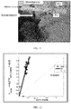
- FIG. 12 illustrates an example plot between VOUR_TBPR and the anemometer flow velocity ( vanem ), according to some embodiments of the present disclosure.
- the slope of the regression line F corr ( G ) is, for example, 4.34 (the theoretically value is 4.83).
- Various embodiments disclosed methods and system for pulmonary health monitoring are able to provide an end-to-end solution for assessing the pulmonary health of the subject.
- the blow device with ultrasonic phase detection technique available in the present disclosure is capable of capturing very sensitive tidal signal and thus provides a cost effective solution for the pulmonary health monitoring.
- LWL- ridge regression based machine learning technique with multiple physiological features increased the accuracy of the system 200.
- the hardware device can be any kind of device which can be programmed including e.g. any kind of computer like a server or a personal computer, or the like, or any combination thereof.
- the device may also include means which could be e.g. hardware means like e.g. an application-specific integrated circuit (ASIC), a field-programmable gate array (FPGA), or a combination of hardware and software means, e.g.
- ASIC application-specific integrated circuit
- FPGA field-programmable gate array
- the means can include both hardware means and software means.
- the method embodiments described herein could be implemented in hardware and software.
- the device may also include software means.
- the embodiments may be implemented on different hardware devices, e.g. using a plurality of CPUs.
- the embodiments herein can comprise hardware and software elements.
- the embodiments that are implemented in software include but are not limited to, firmware, resident software, microcode, etc.
- the functions performed by various modules described herein may be implemented in other modules or combinations of other modules.
- a computer-usable or computer readable medium can be any apparatus that can comprise, store, communicate, propagate, or transport the program for use by or in connection with the instruction execution system, apparatus, or device.
- a computer-readable storage medium refers to any type of physical memory on which information or data readable by a processor may be stored.
- a computer-readable storage medium may store instructions for execution by one or more processors, including instructions for causing the processor(s) to perform steps or stages consistent with the embodiments described herein.
- the term "computer-readable medium” should be understood to include tangible items and exclude carrier waves and transient signals, i.e., be non-transitory. Examples include random access memory (RAM), read-only memory (ROM), volatile memory, nonvolatile memory, hard drives, CD ROMs, DVDs, flash drives, disks, and any other known physical storage media.
Landscapes
- Health & Medical Sciences (AREA)
- Life Sciences & Earth Sciences (AREA)
- Engineering & Computer Science (AREA)
- Physics & Mathematics (AREA)
- Surgery (AREA)
- Public Health (AREA)
- Pathology (AREA)
- Veterinary Medicine (AREA)
- Biomedical Technology (AREA)
- Heart & Thoracic Surgery (AREA)
- Medical Informatics (AREA)
- Molecular Biology (AREA)
- Physiology (AREA)
- Animal Behavior & Ethology (AREA)
- General Health & Medical Sciences (AREA)
- Biophysics (AREA)
- Artificial Intelligence (AREA)
- Pulmonology (AREA)
- Signal Processing (AREA)
- Computer Vision & Pattern Recognition (AREA)
- Psychiatry (AREA)
- Evolutionary Computation (AREA)
- Fuzzy Systems (AREA)
- Mathematical Physics (AREA)
- Computer Networks & Wireless Communication (AREA)
- Measurement Of The Respiration, Hearing Ability, Form, And Blood Characteristics Of Living Organisms (AREA)
Applications Claiming Priority (1)
| Application Number | Priority Date | Filing Date | Title |
|---|---|---|---|
| IN201621038666 | 2016-11-11 |
Publications (2)
| Publication Number | Publication Date |
|---|---|
| EP3320840A1 true EP3320840A1 (fr) | 2018-05-16 |
| EP3320840B1 EP3320840B1 (fr) | 2022-08-17 |
Family
ID=60320713
Family Applications (1)
| Application Number | Title | Priority Date | Filing Date |
|---|---|---|---|
| EP17201120.7A Active EP3320840B1 (fr) | 2016-11-11 | 2017-11-10 | Système et procédé de surveillance de la santé pulmonaire |
Country Status (4)
| Country | Link |
|---|---|
| US (1) | US10898107B2 (fr) |
| EP (1) | EP3320840B1 (fr) |
| JP (1) | JP6557314B2 (fr) |
| AU (1) | AU2017261451B2 (fr) |
Cited By (2)
| Publication number | Priority date | Publication date | Assignee | Title |
|---|---|---|---|---|
| CN112926096A (zh) * | 2021-02-07 | 2021-06-08 | 厦门兆信物之联智能科技有限公司 | 一种基于区块链技术与普通电子健康档案系统融合追溯算法 |
| CN117952566A (zh) * | 2024-03-25 | 2024-04-30 | 南京审计大学 | 基于岭回归机器学习的项目成本预测方法及计算机系统 |
Citations (4)
| Publication number | Priority date | Publication date | Assignee | Title |
|---|---|---|---|---|
| US4103679A (en) * | 1977-03-22 | 1978-08-01 | Biosonics, Inc. | Method and apparatus for measuring blood flow noninvasively |
| EP0100584A2 (fr) * | 1982-05-17 | 1984-02-15 | The BOC Group, Inc. | Débitmètre à ultrasons |
| WO1998000685A2 (fr) * | 1996-06-28 | 1998-01-08 | Rocky Mountain Research, Inc. | Procede et dispositif debimetrique a correction en fonction de la temperature et de la densite |
| EP3263028A1 (fr) * | 2016-06-29 | 2018-01-03 | Vrije Universiteit Brussel | Procédés améliorés de détermination de propriétés respiratoires et système associé |
Family Cites Families (7)
| Publication number | Priority date | Publication date | Assignee | Title |
|---|---|---|---|---|
| US4736750A (en) * | 1981-04-24 | 1988-04-12 | Valdespino Joseph M | Apparatus for testing pulmonary functions |
| US6099481A (en) * | 1997-11-03 | 2000-08-08 | Ntc Technology, Inc. | Respiratory profile parameter determination method and apparatus |
| US20090048500A1 (en) | 2005-04-20 | 2009-02-19 | Respimetrix, Inc. | Method for using a non-invasive cardiac and respiratory monitoring system |
| CN102014745B (zh) | 2008-05-09 | 2013-06-19 | 皇家飞利浦电子股份有限公司 | 患者的非接触呼吸监测 |
| DE102008063503A1 (de) * | 2008-12-17 | 2010-08-05 | Ganshorn Medizin Electronic Gmbh | Lungendiagnosegerät mit vier Ultraschallelementen |
| DK2322917T3 (da) * | 2009-11-17 | 2012-05-29 | Ndd Medizintechnik Ag | Fremgangsmåde til signallineariseringen af et gassensorudgangssignal |
| CN104736055A (zh) | 2012-05-30 | 2015-06-24 | 瑞思迈传感器技术有限公司 | 用于监控心肺健康的方法和设备 |
-
2017
- 2017-11-10 US US15/809,403 patent/US10898107B2/en active Active
- 2017-11-10 EP EP17201120.7A patent/EP3320840B1/fr active Active
- 2017-11-13 JP JP2017217991A patent/JP6557314B2/ja active Active
- 2017-11-13 AU AU2017261451A patent/AU2017261451B2/en active Active
Patent Citations (4)
| Publication number | Priority date | Publication date | Assignee | Title |
|---|---|---|---|---|
| US4103679A (en) * | 1977-03-22 | 1978-08-01 | Biosonics, Inc. | Method and apparatus for measuring blood flow noninvasively |
| EP0100584A2 (fr) * | 1982-05-17 | 1984-02-15 | The BOC Group, Inc. | Débitmètre à ultrasons |
| WO1998000685A2 (fr) * | 1996-06-28 | 1998-01-08 | Rocky Mountain Research, Inc. | Procede et dispositif debimetrique a correction en fonction de la temperature et de la densite |
| EP3263028A1 (fr) * | 2016-06-29 | 2018-01-03 | Vrije Universiteit Brussel | Procédés améliorés de détermination de propriétés respiratoires et système associé |
Non-Patent Citations (1)
| Title |
|---|
| IOANNIS SPYROGLOU ET AL: "Evaluation of a prediction model based on ridge regression for asthma persistence in preschool children", INTERNATIONAL JOURNAL OF MATHEMATICAL MODELS AND METHODS IN APPLIED SCIENCES, vol. 9, 1 January 2015 (2015-01-01), pages 581 - 591, XP055461033 * |
Cited By (2)
| Publication number | Priority date | Publication date | Assignee | Title |
|---|---|---|---|---|
| CN112926096A (zh) * | 2021-02-07 | 2021-06-08 | 厦门兆信物之联智能科技有限公司 | 一种基于区块链技术与普通电子健康档案系统融合追溯算法 |
| CN117952566A (zh) * | 2024-03-25 | 2024-04-30 | 南京审计大学 | 基于岭回归机器学习的项目成本预测方法及计算机系统 |
Also Published As
| Publication number | Publication date |
|---|---|
| JP6557314B2 (ja) | 2019-08-07 |
| JP2018075378A (ja) | 2018-05-17 |
| AU2017261451A1 (en) | 2018-05-31 |
| US20180220934A1 (en) | 2018-08-09 |
| EP3320840B1 (fr) | 2022-08-17 |
| US10898107B2 (en) | 2021-01-26 |
| AU2017261451B2 (en) | 2018-12-20 |
Similar Documents
| Publication | Publication Date | Title |
|---|---|---|
| Cesareo et al. | Assessment of breathing parameters using an inertial measurement unit (IMU)-based system | |
| US9706946B2 (en) | Spirometer system and methods of data analysis | |
| US7559903B2 (en) | Breathing sound analysis for detection of sleep apnea/popnea events | |
| US7267652B2 (en) | Systems and methods for respiratory event detection | |
| Seppä et al. | Tidal flow variability measured by impedance pneumography relates to childhood asthma risk | |
| CN111246798A (zh) | 呼吸紊乱的自动检测 | |
| Huq et al. | Acoustic breath-phase detection using tracheal breath sounds | |
| US20230190140A1 (en) | Methods and apparatus for detection and monitoring of health parameters | |
| CN103841888A (zh) | 使用呼吸模式识别的呼吸暂停和呼吸不足检测 | |
| Iqbal et al. | Photoplethysmography-based respiratory rate estimation algorithm for health monitoring applications | |
| Ciołek et al. | Automated detection of sleep apnea and hypopnea events based on robust airflow envelope tracking in the presence of breathing artifacts | |
| US10004452B2 (en) | System and methods for estimating respiratory airflow | |
| Savage et al. | Development and validation of a novel non‐contact monitor of nocturnal respiration for identifying sleep‐disordered breathing in patients with heart failure | |
| Amir et al. | Photoplethysmography as a single source for analysis of sleep‐disordered breathing in patients with severe cardiovascular disease | |
| Lee et al. | New rule-based algorithm for real-time detecting sleep apnea and hypopnea events using a nasal pressure signal | |
| US20220167856A1 (en) | Lung function monitoring from heart signals | |
| CN107847185A (zh) | 使用光电体积描记术传感器监测呼吸的方法和设备 | |
| JP6315576B2 (ja) | 寝息呼吸音解析装置及び方法 | |
| Umayahara et al. | Estimation of cough peak flow using cough sounds | |
| Sinharay et al. | The ultrasonic directional tidal breathing pattern sensor: Equitable design realization based on phase information | |
| US10898107B2 (en) | System and method for pulmonary health monitoring | |
| Mendonça et al. | A portable wireless device based on oximetry for sleep apnea detection | |
| Azimi et al. | Automatic apnea-hypopnea events detection using an alternative sensor | |
| Romano et al. | Respiratory rate estimation during walking and running using breathing sounds recorded with a microphone | |
| Steltner et al. | Diagnosis of sleep apnea by automatic analysis of nasal pressure and forced oscillation impedance |
Legal Events
| Date | Code | Title | Description |
|---|---|---|---|
| PUAI | Public reference made under article 153(3) epc to a published international application that has entered the european phase |
Free format text: ORIGINAL CODE: 0009012 |
|
| STAA | Information on the status of an ep patent application or granted ep patent |
Free format text: STATUS: THE APPLICATION HAS BEEN PUBLISHED |
|
| AK | Designated contracting states |
Kind code of ref document: A1 Designated state(s): AL AT BE BG CH CY CZ DE DK EE ES FI FR GB GR HR HU IE IS IT LI LT LU LV MC MK MT NL NO PL PT RO RS SE SI SK SM TR |
|
| AX | Request for extension of the european patent |
Extension state: BA ME |
|
| STAA | Information on the status of an ep patent application or granted ep patent |
Free format text: STATUS: REQUEST FOR EXAMINATION WAS MADE |
|
| 17P | Request for examination filed |
Effective date: 20181116 |
|
| RBV | Designated contracting states (corrected) |
Designated state(s): AL AT BE BG CH CY CZ DE DK EE ES FI FR GB GR HR HU IE IS IT LI LT LU LV MC MK MT NL NO PL PT RO RS SE SI SK SM TR |
|
| STAA | Information on the status of an ep patent application or granted ep patent |
Free format text: STATUS: REQUEST FOR EXAMINATION WAS MADE |
|
| STAA | Information on the status of an ep patent application or granted ep patent |
Free format text: STATUS: EXAMINATION IS IN PROGRESS |
|
| 17Q | First examination report despatched |
Effective date: 20210301 |
|
| STAA | Information on the status of an ep patent application or granted ep patent |
Free format text: STATUS: EXAMINATION IS IN PROGRESS |
|
| GRAP | Despatch of communication of intention to grant a patent |
Free format text: ORIGINAL CODE: EPIDOSNIGR1 |
|
| STAA | Information on the status of an ep patent application or granted ep patent |
Free format text: STATUS: GRANT OF PATENT IS INTENDED |
|
| INTG | Intention to grant announced |
Effective date: 20220228 |
|
| GRAS | Grant fee paid |
Free format text: ORIGINAL CODE: EPIDOSNIGR3 |
|
| RIN1 | Information on inventor provided before grant (corrected) |
Inventor name: DATTA, SHREYASI Inventor name: GHOSH, DEBKUMAR Inventor name: PAL, ARPAN Inventor name: CHAKRAVARTY, TAPAS Inventor name: DESHPANDE, PARIJAT DILIP Inventor name: SINHARAY, ARIJIT Inventor name: RAKSHIT, RAJ |
|
| GRAA | (expected) grant |
Free format text: ORIGINAL CODE: 0009210 |
|
| STAA | Information on the status of an ep patent application or granted ep patent |
Free format text: STATUS: THE PATENT HAS BEEN GRANTED |
|
| AK | Designated contracting states |
Kind code of ref document: B1 Designated state(s): AL AT BE BG CH CY CZ DE DK EE ES FI FR GB GR HR HU IE IS IT LI LT LU LV MC MK MT NL NO PL PT RO RS SE SI SK SM TR |
|
| REG | Reference to a national code |
Ref country code: CH Ref legal event code: EP |
|
| REG | Reference to a national code |
Ref country code: DE Ref legal event code: R096 Ref document number: 602017060692 Country of ref document: DE |
|
| REG | Reference to a national code |
Ref country code: IE Ref legal event code: FG4D |
|
| REG | Reference to a national code |
Ref country code: AT Ref legal event code: REF Ref document number: 1511635 Country of ref document: AT Kind code of ref document: T Effective date: 20220915 |
|
| REG | Reference to a national code |
Ref country code: NL Ref legal event code: FP |
|
| REG | Reference to a national code |
Ref country code: LT Ref legal event code: MG9D |
|
| PG25 | Lapsed in a contracting state [announced via postgrant information from national office to epo] |
Ref country code: SE Free format text: LAPSE BECAUSE OF FAILURE TO SUBMIT A TRANSLATION OF THE DESCRIPTION OR TO PAY THE FEE WITHIN THE PRESCRIBED TIME-LIMIT Effective date: 20220817 Ref country code: RS Free format text: LAPSE BECAUSE OF FAILURE TO SUBMIT A TRANSLATION OF THE DESCRIPTION OR TO PAY THE FEE WITHIN THE PRESCRIBED TIME-LIMIT Effective date: 20220817 Ref country code: PT Free format text: LAPSE BECAUSE OF FAILURE TO SUBMIT A TRANSLATION OF THE DESCRIPTION OR TO PAY THE FEE WITHIN THE PRESCRIBED TIME-LIMIT Effective date: 20221219 Ref country code: NO Free format text: LAPSE BECAUSE OF FAILURE TO SUBMIT A TRANSLATION OF THE DESCRIPTION OR TO PAY THE FEE WITHIN THE PRESCRIBED TIME-LIMIT Effective date: 20221117 Ref country code: LV Free format text: LAPSE BECAUSE OF FAILURE TO SUBMIT A TRANSLATION OF THE DESCRIPTION OR TO PAY THE FEE WITHIN THE PRESCRIBED TIME-LIMIT Effective date: 20220817 Ref country code: LT Free format text: LAPSE BECAUSE OF FAILURE TO SUBMIT A TRANSLATION OF THE DESCRIPTION OR TO PAY THE FEE WITHIN THE PRESCRIBED TIME-LIMIT Effective date: 20220817 Ref country code: FI Free format text: LAPSE BECAUSE OF FAILURE TO SUBMIT A TRANSLATION OF THE DESCRIPTION OR TO PAY THE FEE WITHIN THE PRESCRIBED TIME-LIMIT Effective date: 20220817 |
|
| REG | Reference to a national code |
Ref country code: AT Ref legal event code: MK05 Ref document number: 1511635 Country of ref document: AT Kind code of ref document: T Effective date: 20220817 |
|
| PG25 | Lapsed in a contracting state [announced via postgrant information from national office to epo] |
Ref country code: PL Free format text: LAPSE BECAUSE OF FAILURE TO SUBMIT A TRANSLATION OF THE DESCRIPTION OR TO PAY THE FEE WITHIN THE PRESCRIBED TIME-LIMIT Effective date: 20220817 Ref country code: IS Free format text: LAPSE BECAUSE OF FAILURE TO SUBMIT A TRANSLATION OF THE DESCRIPTION OR TO PAY THE FEE WITHIN THE PRESCRIBED TIME-LIMIT Effective date: 20221217 Ref country code: HR Free format text: LAPSE BECAUSE OF FAILURE TO SUBMIT A TRANSLATION OF THE DESCRIPTION OR TO PAY THE FEE WITHIN THE PRESCRIBED TIME-LIMIT Effective date: 20220817 Ref country code: GR Free format text: LAPSE BECAUSE OF FAILURE TO SUBMIT A TRANSLATION OF THE DESCRIPTION OR TO PAY THE FEE WITHIN THE PRESCRIBED TIME-LIMIT Effective date: 20221118 |
|
| PG25 | Lapsed in a contracting state [announced via postgrant information from national office to epo] |
Ref country code: SM Free format text: LAPSE BECAUSE OF FAILURE TO SUBMIT A TRANSLATION OF THE DESCRIPTION OR TO PAY THE FEE WITHIN THE PRESCRIBED TIME-LIMIT Effective date: 20220817 Ref country code: RO Free format text: LAPSE BECAUSE OF FAILURE TO SUBMIT A TRANSLATION OF THE DESCRIPTION OR TO PAY THE FEE WITHIN THE PRESCRIBED TIME-LIMIT Effective date: 20220817 Ref country code: ES Free format text: LAPSE BECAUSE OF FAILURE TO SUBMIT A TRANSLATION OF THE DESCRIPTION OR TO PAY THE FEE WITHIN THE PRESCRIBED TIME-LIMIT Effective date: 20220817 Ref country code: DK Free format text: LAPSE BECAUSE OF FAILURE TO SUBMIT A TRANSLATION OF THE DESCRIPTION OR TO PAY THE FEE WITHIN THE PRESCRIBED TIME-LIMIT Effective date: 20220817 Ref country code: CZ Free format text: LAPSE BECAUSE OF FAILURE TO SUBMIT A TRANSLATION OF THE DESCRIPTION OR TO PAY THE FEE WITHIN THE PRESCRIBED TIME-LIMIT Effective date: 20220817 Ref country code: AT Free format text: LAPSE BECAUSE OF FAILURE TO SUBMIT A TRANSLATION OF THE DESCRIPTION OR TO PAY THE FEE WITHIN THE PRESCRIBED TIME-LIMIT Effective date: 20220817 |
|
| REG | Reference to a national code |
Ref country code: DE Ref legal event code: R097 Ref document number: 602017060692 Country of ref document: DE |
|
| PG25 | Lapsed in a contracting state [announced via postgrant information from national office to epo] |
Ref country code: SK Free format text: LAPSE BECAUSE OF FAILURE TO SUBMIT A TRANSLATION OF THE DESCRIPTION OR TO PAY THE FEE WITHIN THE PRESCRIBED TIME-LIMIT Effective date: 20220817 Ref country code: EE Free format text: LAPSE BECAUSE OF FAILURE TO SUBMIT A TRANSLATION OF THE DESCRIPTION OR TO PAY THE FEE WITHIN THE PRESCRIBED TIME-LIMIT Effective date: 20220817 |
|
| PLBE | No opposition filed within time limit |
Free format text: ORIGINAL CODE: 0009261 |
|
| STAA | Information on the status of an ep patent application or granted ep patent |
Free format text: STATUS: NO OPPOSITION FILED WITHIN TIME LIMIT |
|
| PG25 | Lapsed in a contracting state [announced via postgrant information from national office to epo] |
Ref country code: MC Free format text: LAPSE BECAUSE OF FAILURE TO SUBMIT A TRANSLATION OF THE DESCRIPTION OR TO PAY THE FEE WITHIN THE PRESCRIBED TIME-LIMIT Effective date: 20220817 Ref country code: AL Free format text: LAPSE BECAUSE OF FAILURE TO SUBMIT A TRANSLATION OF THE DESCRIPTION OR TO PAY THE FEE WITHIN THE PRESCRIBED TIME-LIMIT Effective date: 20220817 |
|
| P01 | Opt-out of the competence of the unified patent court (upc) registered |
Effective date: 20230526 |
|
| 26N | No opposition filed |
Effective date: 20230519 |
|
| REG | Reference to a national code |
Ref country code: BE Ref legal event code: MM Effective date: 20221130 |
|
| PG25 | Lapsed in a contracting state [announced via postgrant information from national office to epo] |
Ref country code: SI Free format text: LAPSE BECAUSE OF FAILURE TO SUBMIT A TRANSLATION OF THE DESCRIPTION OR TO PAY THE FEE WITHIN THE PRESCRIBED TIME-LIMIT Effective date: 20220817 Ref country code: LU Free format text: LAPSE BECAUSE OF NON-PAYMENT OF DUE FEES Effective date: 20221110 |
|
| PG25 | Lapsed in a contracting state [announced via postgrant information from national office to epo] |
Ref country code: IE Free format text: LAPSE BECAUSE OF NON-PAYMENT OF DUE FEES Effective date: 20221110 |
|
| PG25 | Lapsed in a contracting state [announced via postgrant information from national office to epo] |
Ref country code: BE Free format text: LAPSE BECAUSE OF NON-PAYMENT OF DUE FEES Effective date: 20221130 |
|
| PGFP | Annual fee paid to national office [announced via postgrant information from national office to epo] |
Ref country code: NL Payment date: 20231124 Year of fee payment: 7 |
|
| PGFP | Annual fee paid to national office [announced via postgrant information from national office to epo] |
Ref country code: GB Payment date: 20231121 Year of fee payment: 7 |
|
| PGFP | Annual fee paid to national office [announced via postgrant information from national office to epo] |
Ref country code: FR Payment date: 20231123 Year of fee payment: 7 Ref country code: DE Payment date: 20231127 Year of fee payment: 7 Ref country code: CH Payment date: 20231201 Year of fee payment: 7 |
|
| PG25 | Lapsed in a contracting state [announced via postgrant information from national office to epo] |
Ref country code: HU Free format text: LAPSE BECAUSE OF FAILURE TO SUBMIT A TRANSLATION OF THE DESCRIPTION OR TO PAY THE FEE WITHIN THE PRESCRIBED TIME-LIMIT; INVALID AB INITIO Effective date: 20171110 |
|
| PG25 | Lapsed in a contracting state [announced via postgrant information from national office to epo] |
Ref country code: CY Free format text: LAPSE BECAUSE OF FAILURE TO SUBMIT A TRANSLATION OF THE DESCRIPTION OR TO PAY THE FEE WITHIN THE PRESCRIBED TIME-LIMIT Effective date: 20220817 |