EP3320802B1 - Gambling table provided with casters and retractable feet - Google Patents
Gambling table provided with casters and retractable feet Download PDFInfo
- Publication number
- EP3320802B1 EP3320802B1 EP17200928.4A EP17200928A EP3320802B1 EP 3320802 B1 EP3320802 B1 EP 3320802B1 EP 17200928 A EP17200928 A EP 17200928A EP 3320802 B1 EP3320802 B1 EP 3320802B1
- Authority
- EP
- European Patent Office
- Prior art keywords
- feet
- pair
- supporting structure
- stabilizing
- ground
- Prior art date
- Legal status (The legal status is an assumption and is not a legal conclusion. Google has not performed a legal analysis and makes no representation as to the accuracy of the status listed.)
- Active
Links
- 208000001613 Gambling Diseases 0.000 title 1
- 230000000087 stabilizing effect Effects 0.000 claims description 49
- 238000005096 rolling process Methods 0.000 claims description 46
- 230000007246 mechanism Effects 0.000 claims description 35
- 125000006850 spacer group Chemical group 0.000 claims description 17
- 230000000284 resting effect Effects 0.000 claims description 7
- 235000004443 Ricinus communis Nutrition 0.000 claims description 6
- 240000000528 Ricinus communis Species 0.000 claims 4
- 230000006641 stabilisation Effects 0.000 description 98
- 238000011105 stabilization Methods 0.000 description 62
- 238000006073 displacement reaction Methods 0.000 description 18
- 230000000694 effects Effects 0.000 description 3
- 235000020004 porter Nutrition 0.000 description 2
- 230000007704 transition Effects 0.000 description 2
- 241000287107 Passer Species 0.000 description 1
- 241001080024 Telles Species 0.000 description 1
- 230000007547 defect Effects 0.000 description 1
- 230000000630 rising effect Effects 0.000 description 1
- 230000001360 synchronised effect Effects 0.000 description 1
Images
Classifications
-
- A—HUMAN NECESSITIES
- A47—FURNITURE; DOMESTIC ARTICLES OR APPLIANCES; COFFEE MILLS; SPICE MILLS; SUCTION CLEANERS IN GENERAL
- A47B—TABLES; DESKS; OFFICE FURNITURE; CABINETS; DRAWERS; GENERAL DETAILS OF FURNITURE
- A47B25/00—Card tables; Tables for other games
- A47B25/003—Card tables; Tables for other games for table tennis
- A47B2025/006—Card tables; Tables for other games for table tennis with retractable wheels
-
- A—HUMAN NECESSITIES
- A47—FURNITURE; DOMESTIC ARTICLES OR APPLIANCES; COFFEE MILLS; SPICE MILLS; SUCTION CLEANERS IN GENERAL
- A47B—TABLES; DESKS; OFFICE FURNITURE; CABINETS; DRAWERS; GENERAL DETAILS OF FURNITURE
- A47B3/00—Folding or stowable tables
- A47B3/08—Folding or stowable tables with legs pivoted to top or underframe
- A47B3/083—Folding or stowable tables with legs pivoted to top or underframe with foldable top leaves
- A47B3/087—Folding or stowable tables with legs pivoted to top or underframe with foldable top leaves with struts supporting the legs
Definitions
- the present invention relates to the field of gaming tables.
- game tables such as ping pong, which are foldable to facilitate storage / movement.
- the table according to the invention is essentially characterized in that the table is arranged so that in its playing configuration, at least some of the running feet of said plurality of running feet are spaced from the flat ground.
- All of the stabilization feet are arranged to oppose together the movement of the table on the ground.
- each stabilization foot may have a friction end which opposes the sliding of the foot on the ground when this end is resting on the ground.
- the table has several stabilizing feet each with a castor to allow rolling on the ground, however, these casters of these stabilizing feet are respectively oriented so that when they are all in position. contact with the ground, they then oppose together the rolling of the table because these rollers of the stabilizing feet do not have a common rolling direction.
- the table according to the invention when the table according to the invention is in its play configuration, at least some of the running feet of said plurality of running feet are spaced from the flat ground while each at least one stabilizing foot is in contact with the ground. to oppose the movement of the table on the floor.
- Removing at least some of the running feet from the ground allows at least part of the weight of the table to be transferred to the stabilization feet, which increases the ability of these stabilizing feet to oppose moving the table on the level floor.
- the table according to the invention when placed in its playing configuration, thus exhibits improved stability.
- the table is arranged so that when it is in the play configuration, each stabilization foot is supported on the flat ground. to support the table while all the feet of bearing are removed / not supported from the level ground.
- the connecting mechanism is designed to simultaneously move each at least one stabilization foot relative to the plurality of running feet.
- the control of variation of the relative positioning of the running feet with respect to each at least one stabilizing foot is thus centralized and carried out simultaneously, which facilitates the actuation of the table by the user.
- the table 1 selectively adopts a storage configuration visible from the figure 2 , and a game configuration visible to figures 1 and 4 .
- the first and second flat surfaces 2a1 and 2b1 of the plates 2a, 2b extend in separate planes P1, P2 / not coincident with each other.
- these flat surfaces 2a1, 2b1 of the table in the storage configuration are substantially parallel to each other and are positioned facing each other.
- the plate is then folded and its main flat surfaces 2a1, 2b1 face each other.
- each stabilizing foot 3 is moved away from the ground S and a plurality of said rolling feet 4, in this case all the rolling feet 4, rests on the ground S.
- These rolling feet 4 support the table 1 on the floor S and allow it to roll on the floor S without opposition from the stabilization feet 3.
- the first and second flat surfaces 2a1, 2b1 of the board portions 2a, 2b extend in the same game plane P3 to together form an upper planar game face Sp of the board.
- This game plane P3 is parallel to the ground plane S.
- each stabilization foot rests on the ground S to oppose the movement of the table on the ground while at least some of the rolling feet of said plurality of rolling feet, in this case all the running feet are spaced from the level ground.
- the table thus goes from a storage configuration where the table is compact and easy to move on the floor to a play configuration where the table is deployed and stabilized on the floor to oppose its movement.
- the connecting mechanism is thus adapted so that, in response to the movement of the table 1 between its play and storage configurations, the movements of the stabilizing feet 3 are synchronized with the movements of the running feet 4.
- the handling of the table is thus facilitated while improving its stability in game configuration.
- the link mechanism M is arranged to move each at least one stabilization feet 3 relative to the plurality of running feet 4 in response to an actuation of the link mechanism M by a displacement of the first and second portions of plate 2a, 2b relative to each other.
- the link mechanism M which is linked to the first and second plate portions 2a, 2b is actuated mechanically by the displacement of said first plate portion 2a relative to the second plate portion 2b. Under the effect of this actuation, the link mechanism M forces the plurality of stabilization feet 3 to move relative to the plurality of running feet 4.
- the user can thus control the passage of the table from its storage configuration to its game configuration and vice versa from its game configuration to its storage configuration, by forcing a relative movement between the first and second tray portions 2a, 2b .
- the user raises or lowers the first portion of the plate 2a to move it vis-à-vis the second portion 2b.
- the M link mechanism can also be actuated by displacement of the second plate portion to induce a relative displacement between the first and second plate portions 2a, 2b.
- the mechanism M drives the movement of the various stabilization and rolling feet relative to one another.
- the first and second board portions are moved / deployed until they together form an upper planar game face Sp of the board .
- the linkage mechanism M forces the displacement of the plurality of stabilizing feet 3 relative to the plurality of running feet 4 until all the feet stabilization devices are in contact with the plane ground S and that all the running feet 4 are all moved away from this plane ground S.
- Table 2 is then in the play configuration as on the figures 1 and 4 .
- the stabilization feet 3 are adjusted so that when the table is in the playing configuration, the upper plane face Sp is then parallel to the plane floor S which carries the table. Conversely, throughout the passage of the table from its playing configuration to its storage configuration, the first and second board portions are gradually moved / folded towards each other until they have their main faces 2a1, 2b1. facing each other in a substantially vertical position. During this transition from the play configuration to the storage configuration, the link mechanism M forces the movement of the plurality of stabilizing feet 3 relative to the plurality of rolling feet 4 until all the rolling feet 4 are in contact with the ground plane S and that all the stabilization feet 3 are all spaced / moved away from this plane ground S. Table 1 is then in storage configuration, as on the figure 2 , and it can be simply moved by rolling on the ground plane S.
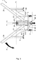
- FIG. 3 Moving the table from its storage configuration to the figure 2 to the game configuration of figures 1 and 4 is illustrated by the figure 3 .
- the arrow F illustrates the lowering force exerted by the user on the first plate portion 2a to move it to a position coplanar with the second plate portion 2b.
- the connecting mechanism M forces the movement of the stabilizing feet 3 relative to the running feet 4. A Once the stabilization feet 3 are all in contact with the plane ground S, the lowering movement of the first plate portion 2a becomes impossible and the table is thus maintained in a stable playing configuration.
- the stabilization feet comprise pads made of flexible material such as rubber to preserve the ground and reduce sliding on the ground. At least some of these pads may be adjustable, for example via a threaded assembly, to adjust the length of each stabilization foot concerned.
- the table can thus be stabilized even on a ground having defects of flatness.
- each of the rollers R of the four rolling feet 4 has an orientation pivot which is specific to it and which extends in a direction perpendicular to said rolling surface Pr.
- the connecting mechanism M comprises a rigid supporting structure 5 on which are mounted at least four of the running feet 4. These four of the running feet together form said plurality of running feet.
- This supporting structure 5 here comprises a horizontal H-shaped base (when observed in top view). Each of the four ends of the H has one of the four roller feet.
- the supporting structure 5 also has a rising portion extending perpendicularly relative to a plane in which the H-shaped base extends.
- the rollers of these four rolling feet 4 together defining a rolling plane Pr of the rollers of these four feet.
- the first plate portion 2a is mounted to pivot relative to this supporting structure 5 via at least one first articulation axis X10.
- the second plate portion 2b is also mounted to pivot relative to this supporting structure 5 via at least one second articulation axis X20 which is parallel to said first articulation axis X10.
- the actuating part M0 forms a lever arm mounted to move relative to the supporting structure 5 along an axis X30.
- the two legs of the third pair of stabilizing legs 3c are mechanically linked together to be moved together between their extended and retracted positions.
- the table has at least a first spreader bar B1, in this case two bars B1, each articulated on the one hand to the supporting structure 5 and on the other hand to said first pair 3a of stabilization feet 3.
- These bars B1 are placed symmetrically on either side of a plane of longitudinal section of the table which is perpendicular to the running surface Pr.
- Each first spacer bar makes it possible to prevent the movement of said first pair 3a of stabilizing feet relative to the supporting structure 5 as long as the first portion of the plate 2a is stationary relative to the supporting structure 5.
- This first bar of spacing B1 also allows the feet to be folded down to limit the bulk in the storage configuration.
- the mechanical connection of the actuating part M0 to the first spacer bar B1 comprises a connecting rod M1 which is on one side in a pivot connection with the actuating part M0 and on the other hand in pivot connection with the first spreader bar B1.
- These pivot connections are along pivot axes parallel to the X10 and X20 axes.
- the position and the displacement of the first actuating part M0 between its first and second positions, and vice versa depend on the position adopted by the first spacer bar B1 to which the device is mechanically connected. MO room.
- each actuating part M0 is coupled to only one of the feet of the pair 3c and that the displacement of each actuating part is induced, via the link mechanism M, by the displacement of only one of the plate portions which corresponds to it relative to the supporting structure.
- the game table 1 comprises at least one second spreader bar B2, in this case two bars B2, each articulated on the one hand to the supporting structure 5 and on the other hand to said second pair 3b of feet. stabilization 3. These bars B2 are placed symmetrically on either side of the plane of longitudinal section which is perpendicular to the running plane of the table.
- Each second spacer bar B2 makes it possible to prevent the movement of said second pair of stabilization feet relative to the supporting structure as long as the second portion of the platform is stationary relative to this supporting structure.
- Each second B2 spacer bar also makes it possible to fold down the feet of the pair 3b to limit the bulk in the storage configuration.
- each first spreader bar B1 makes it possible to stabilize the position of the first pair 3a of stabilization feet 3 with respect to the supporting structure 5 as long as the first portion of the plate 2a remains stationary relative to the structure. carrier 5.
- each second spreader bar B2 makes it possible to stabilize the position of the second pair 3b of stabilization feet 3 with respect to the supporting structure 5 as long as the second portion of plate 2b remains stationary relative to the supporting structure. to the supporting structure 5.
- a second actuating part can be mechanically connected to only one of the legs of the third pair of legs in order to move it between its extended and retracted positions during the movement of this second actuating part relative to the supporting structure 5.
- this second actuating part can be connected to one of the second spacer bars B2 so that the movement of the second portion of the plate vis-à-vis the supporting structure 5 causes the displacement of this second actuating part and the displacement of this foot of the third pair of stabilization feet 3c.
- the table further comprises a pair of first articulation bars C1 each having a lower end articulated to the supporting structure 5 in a direction of articulation common to this pair of first articulation bars C1.
- Each of these C1 bars has an upper end to which the first plate portion 2a is assembled.
- This pair of first articulation bars C1 connects the supporting structure 5 to the first plate portion 2a.
- the lower ends of the articulation bars C1 are each articulated on the supporting structure via pivots of axes X2 preferably carried by the horizontal H-shaped base of the supporting structure 5.
- the upper ends of the articulation bars C1 are assembled at the first portion of plate 2a by pivots with axes parallel to said axes X2.
- the actuating part MO it is also possible for the actuating part MO to be articulated to one of the bars of these first articulation bars C1, instead of being articulated to the first spreader bar B1.
- the movement of the actuating part MO between its first and second positions is a function of the position, with respect to the supporting structure 5, of the first articulation bar C1 to which this actuating part M0 is articulated.
- the table includes a pair of second C2 hinge bars. Each of these bars C2 has a lower end articulated to the supporting structure 5 in an articulation direction X3 common to this pair of second articulation bars C2. Each upper end of bar C2 is assembled with the second plate portion 2b. This pair of second C2 articulation bars connects the supporting structure to the second plate portion 2b so that this second plate portion is at least partially supported by the supporting structure 5 via this pair of second articulation bars C2.
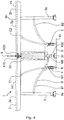
- the first articulation axis X10 allowing the first portion of plate 2a to pivot relative to the supporting structure 5 is assembled to the supporting structure 5 via a first substantially vertical slide G1 visible at the bottom. figure 4 .
- This slide G1 allows the first articulation axis X10 to move along the slide G1 during the passage of the table between its play and storage configurations.
- the second articulation axis X20 allowing the second plate portion 2b to pivot relative to the supporting structure 5 is assembled to this supporting structure via a second substantially vertical slideway G2 visible at the bottom. figure 4 .
- substantially vertical is meant an orientation of plus or minus 20 ° relative to a vertical plane.
- This second slide G2 allows the second articulation axis X20 to move along the slide G2 during the passage of the table between its game and storage configurations.
- first and second articulation axes X10, X20 are mutually parallel.
- X20 is formed along a lateral edge of a plate portion 2a, 2b which corresponds to it, the presence of these slides G1, G2 makes it possible to lower the height of the pivot axes X10, X20 by the table in storage configuration. This limits its vertical size.
- the table comprises a net 6 arranged to extend along a net plane perpendicular to said upper flat playing face Sp of the table top in game configuration. This net plane passes through a limit extending between the first and second tray portions 2a, 2b. This table is suitable for playing ping pong.
- Different actuation mechanisms can be used to mechanically connect the actuating part (s) M0 to at least one of the feet of said third pair 3c of stabilization feet which corresponds to it.
- an actuation mechanism may be a pinion / rack mechanism, the pinion being mounted at the end of the actuating part to cause the displacement of the rack itself connected to the third pair of stabilization feet.
- this actuation mechanism can be a cam and cam follower mechanism, the cam being mounted at the end of the actuating part to cause the movement of the cam follower itself connected to the third pair of stabilizing feet.
- this actuating mechanism can be a helical link mechanism comprising a screw and a nut, the screw being rotated by the rotation of the end of the control part to cause the displacement of the nut. which is itself connected to the third pair of stabilization feet to move it in translation.
- connection between the actuating part and the third pair of stabilizing feet can be envisaged as long as they make it possible to control the displacement of the third pair of feet relative to the supporting structure as a function of the pivoting of the first. tray portion with respect to this same supporting structure.
- the link mechanism M may include a mechanical actuation control that can be actuated mechanically by the force of a user of the table to move said at least one stabilization foot 3 relative to the plurality of rolling feet 4 and thus moving said at least some of the rolling feet of said plurality of running feet away from the ground.
- This mechanical actuation control is, for example, a pedal actuable by the foot by the user or a joystick actuable manually by the user.
- a mechanical actuation control such as a pedal, on each side of the table.
- Each mechanical actuation control can also be provided to control the movement of said at least one of the stabilizing feet which corresponds to it with respect to the plurality of running feet 4 while the first and second plate portions 2a, 2b remain motionless in relation to each other.
- the movement of the stabilization feet can be decorrelated from the movement of the plate portions relative to each other.
- a mechanical actuation control may have a control offset accessible from either side of the table to allow the user to move said at least one stabilization foot from one or the other. other side of the table.
Description
La présente invention concerne le domaine des tables de jeu.The present invention relates to the field of gaming tables.
Il est connu des tables de jeu, tel que du ping pong, qui son pliables pour en faciliter le rangement / déplacement.There are known game tables, such as ping pong, which are foldable to facilitate storage / movement.
Par exemple, on connait du document brevet
- un plateau comprenant une première portion de plateau présentant une première surface plane et une seconde portion de plateau présentant une seconde surface plane;
- au moins un pied de stabilisation ;
- des pieds de roulement chacun équipé d'au moins une roulette pour le roulage de la table sur un sol plan ;
- un mécanisme de liaison reliant le plateau d'une part à chaque au moins un pied de stabilisation et d'autre part à chacun des pieds de roulement ;
- a platen comprising a first platen portion having a first planar surface and a second platen portion having a second planar surface;
- at least one stabilization foot;
- running feet each equipped with at least one wheel for rolling the table on a level ground;
- a connecting mechanism connecting the plate on the one hand to each at least one stabilization foot and on the other hand to each of the running feet;
Il a été constaté qu'il est parfois possible, en exerçant une poussée latérale sur la table, de la déplacer sur le sol pendant le jeu. Le confort de jeu peut en être affecté et à la longue les pieds de stabilisation peuvent se dégrader.It has been observed that it is sometimes possible, by exerting a lateral thrust on the table, to move it on the ground during the game. The playing comfort can be affected and in the long run the stabilization feet can deteriorate.
La demande de brevet
Il est souhaitable d'améliorer la stabilité de la table sur le sol lorsque cette table est en configuration de jeu.It is desirable to improve the stability of the table on the floor when this table is in a play configuration.
A cette fin, il est proposé selon l'invention une table de jeu présentant :
- un plateau comprenant une première portion de plateau présentant une première surface plane et une seconde portion de plateau présentant une seconde surface plane;
- au moins un pied de stabilisation ;
- des pieds de roulement chacun équipé d'au moins une roulette pour le roulage de la table sur un sol plan ;
- un mécanisme de liaison reliant le plateau d'une part à chaque au moins un pied de stabilisation et d'autre part à chacun des pieds de roulement ;
- a platen comprising a first platen portion having a first planar surface and a second platen portion having a second planar surface;
- at least one stabilization foot;
- running feet each equipped with at least one wheel for rolling the table on a level ground;
- a connecting mechanism connecting the plate on the one hand to each at least one stabilization foot and on the other hand to each of the running feet;
La table selon l'invention est essentiellement caractérisée en ce que la table est agencée pour que dans sa configuration de jeu, certains au moins des pieds de roulement de ladite pluralité de pieds de roulement soient écartés du sol plan.The table according to the invention is essentially characterized in that the table is arranged so that in its playing configuration, at least some of the running feet of said plurality of running feet are spaced from the flat ground.
Pour la compréhension de l'invention, par roulement de la table sur le sol, on entend le déplacement de la table en contact avec le sol uniquement par roulage de roulettes de pieds de roulement sur ce sol, ce roulement se faisant sans qu'aucun pied de stabilisation ne soit en appui / contact avec le sol.For the understanding of the invention, by rolling of the table on the ground, is meant the displacement of the table in contact with the ground only by rolling of the rollers of the running feet on this ground, this rolling taking place without any stabilization foot is in contact with the ground.
Lorsque la table est dans sa configuration de rangement, seuls les pieds d'une pluralité de pieds de roulement équipés de roulette sont en contact sur le sol. La table peut ainsi être déplacée sur le sol par roulement en la poussant. Dans cette configuration de rangement, tous les pieds de stabilisation sont écartés du sol et ne peuvent donc pas s'opposer au déplacement de la table sur le sol.When the table is in its storage configuration, only the feet of a plurality of running feet equipped with wheels are in contact with the ground. The table can thus be moved on the floor by rolling by pushing it. In this storage configuration, all the stabilization feet are spaced from the ground and therefore cannot oppose the movement of the table on the ground.
A contrario, lorsque la table est dans sa configuration de jeu :
- d'une part les première et seconde surfaces planes qui s'étendent dans un même plan de jeu pour former ensemble une face plane supérieure de jeu du plateau sur laquelle le/les utilisateur pourront jouer; et
- d'autre part, chaque pied de stabilisation est en appui sur le sol pour y supporter la table.
- on the one hand, the first and second flat surfaces which extend in the same game plane to together form an upper flat playing face of the board on which the user (s) can play; and
- on the other hand, each stabilization foot rests on the ground to support the table there.
L' ensemble des pieds de stabilisation sont agencés pour s'opposer ensemble au déplacement de la table sur le sol.All of the stabilization feet are arranged to oppose together the movement of the table on the ground.
Pour cela, chaque pied de stabilisation peut présenter une extrémité de frottement qui s'oppose au glissement du pied sur le sol lorsque cette extrémité est en appui sur le sol. Dans certains cas, il est possible que la table présente plusieurs pieds de stabilisation chacun doté d'une roulette pour permettre le roulement sur le sol, toutefois, ces roulettes de ces pieds de stabilisation sont respectivement orientées de manière que lorsqu'elles sont toutes en contact sur le sol, elles s'opposent alors ensemble au roulement de la table car ces roulettes des pieds de stabilisation n'ont pas de direction de roulement commune.For this, each stabilization foot may have a friction end which opposes the sliding of the foot on the ground when this end is resting on the ground. In some cases, it is possible that the table has several stabilizing feet each with a castor to allow rolling on the ground, however, these casters of these stabilizing feet are respectively oriented so that when they are all in position. contact with the ground, they then oppose together the rolling of the table because these rollers of the stabilizing feet do not have a common rolling direction.
Par ailleurs, lorsque la table selon l'invention est dans sa configuration de jeu certains au moins des pieds de roulement de ladite pluralité de pieds de roulement sont écartés du sol plan alors que chaque au moins un pied de stabilisation est en contact avec le sol pour s'opposer au déplacement de la table sur le sol.Furthermore, when the table according to the invention is in its play configuration, at least some of the running feet of said plurality of running feet are spaced from the flat ground while each at least one stabilizing foot is in contact with the ground. to oppose the movement of the table on the floor.
Le fait d'écarter certains au moins des pieds de roulement vis-à-vis du sol permet de reporter au moins une partie du poids de la table sur les pieds de stabilisation ce qui augmente la capacité de ces pieds de stabilisation à s'opposer au déplacement de la table sur le sol plan.Removing at least some of the running feet from the ground allows at least part of the weight of the table to be transferred to the stabilization feet, which increases the ability of these stabilizing feet to oppose moving the table on the level floor.
La table selon l'invention, lorsque placée dans sa configuration de jeu, présente ainsi une stabilité améliorée. Comme cela sera décrit ci-après, en référence à un mode de réalisation préférentiel de la table selon l'invention, la table est agencée pour que lorsqu'elle est en configuration de jeu, chaque pied de stabilisation soit en appui sur le sol plan pour supporter la table alors que tous les pieds de roulement sont éloignés / non appuyés du sol plan.The table according to the invention, when placed in its playing configuration, thus exhibits improved stability. As will be described below, with reference to a preferred embodiment of the table according to the invention, the table is arranged so that when it is in the play configuration, each stabilization foot is supported on the flat ground. to support the table while all the feet of bearing are removed / not supported from the level ground.
Dans ce mode on est certain qu'en configuration de jeu, aucune roulette n'est en contact avec le sol ce qui augmente la capacité de résistance au glissement des pieds de stabilisation sur le sol.In this mode, it is certain that in the game configuration, no wheel is in contact with the ground, which increases the resistance to sliding of the stabilizing feet on the ground.
Préférentiellement, le mécanisme de liaison est agencé pour déplacer simultanément chaque au moins un pied de stabilisation par rapport à la pluralité de pieds de roulement.Preferably, the connecting mechanism is designed to simultaneously move each at least one stabilization foot relative to the plurality of running feet.
La commande de variation de positionnement relatif des pieds de roulement par rapport à chaque au moins un pied de stabilisation est ainsi centralisée et réalisée simultanément ce qui facilite l'actionnement de la table par l'utilisateur.The control of variation of the relative positioning of the running feet with respect to each at least one stabilizing foot is thus centralized and carried out simultaneously, which facilitates the actuation of the table by the user.
D'autres caractéristiques et avantages de l'invention ressortiront clairement de la description qui en est faite ci-après, à titre indicatif et nullement limitatif, en référence aux dessins annexés, dans lesquels:
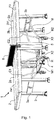
- la
figure 1 illustre une vue en perspective de la table selon l'invention alors qu'elle est en configuration de jeu sur un sol plan; - la
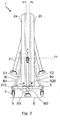
figure 2 illustre une vue de côté de la table selon l'invention alors qu'elle est en configuration de rangement avec sa troisième paire de pieds de stabilisation éloignée du sol plan ; - la
figure 3 illustre une vue de côté de la table selon l'invention alors qu'elle est entrain de passer de sa configuration de rangement vers sa configuration de jeu, les première et seconde portions de plateau étant progressivement dépliées et la troisième paire de pieds de stabilisation se rapprochant progressivement du sol plan sous l'effet d'un mécanisme de liaison reliant ces première et seconde portions de plateau à la troisième paire de pieds de stabilisation ; - la
figure 4 illustre une vue de côté de la table selon l'invention alors qu'elle est en configuration de jeu avec ses trois paires de pieds de stabilisation simultanément en contact sur le sol plan et ses pieds de roulement tous éloignés de ce sol plan.
- the
figure 1 illustrates a perspective view of the table according to the invention while it is in the playing configuration on a level ground; - the
figure 2 illustrates a side view of the table according to the invention while it is in the storage configuration with its third pair of stabilization feet remote from the flat ground; - the
figure 3 illustrates a side view of the table according to the invention as it is moving from its storage configuration to its play configuration, the first and second tray portions being progressively unfolded and the third pair of stabilization feet being progressively bringing closer to the flat ground under the effect of a mechanism connecting these first and second plate portions to the third pair of stabilization feet; - the
figure 4 illustrates a side view of the table according to the invention while it is in the playing configuration with its three pairs of stabilization feet simultaneously in contact with the flat ground and its running feet all removed from this flat ground.
Comme indiqué précédemment, l'invention concerne une table de jeu 1 présentant :
- un plateau 2 comprenant une première portion de
plateau 2a présentant une première surface plane 2a1 et une seconde portion deplateau 2b présentant une seconde surface plane 2b1; - au moins un pied de stabilisation et préférentiellement une pluralité de pieds de
stabilisation 3; - des pieds de roulement 4 chacun équipé d'au moins une roulette R pour le roulage de la table sur un sol plan S ;
- un mécanisme de liaison M reliant les portions de
plateau stabilisation 3 et d'autre part à chacun des pieds de roulement 4.
- a plate 2 comprising a
first plate portion 2a having a first planar surface 2a1 and asecond plate portion 2b having a second planar surface 2b1; - at least one stabilization foot and preferably a plurality of
stabilization feet 3; - rolling
feet 4 each equipped with at least one roller R for rolling the table on a plane floor S; - a connecting mechanism M connecting the
plate portions stabilization foot 3 and on the other hand to each of the runningfeet 4.
La table 1 adopte sélectivement une configuration de rangement visible à la
Dans la configuration de rangement (
Dans cette configuration de rangement, chaque pied de stabilisation 3 est éloigné du sol S et une pluralité desdits pieds de roulement 4, en l'occurrence tous les pieds de roulement 4 est en appui sur le sol S. Ces pieds de roulement 4 supportent la table 1 sur le sol S et permettent son roulement sur le sol S sans opposition de la part des pieds de stabilisation 3.In this storage configuration, each stabilizing
Dans la configuration de jeu (
Dans cette configuration de jeu, chaque pied de stabilisation est en appui sur le sol S pour s'opposer au déplacement de la table sur le sol alors que certains au moins des pieds de roulement de ladite pluralité de pieds de roulement, en l'occurrence tous les pieds de roulement, sont écartés du sol plan.In this play configuration, each stabilization foot rests on the ground S to oppose the movement of the table on the ground while at least some of the rolling feet of said plurality of rolling feet, in this case all the running feet are spaced from the level ground.
La table passe ainsi d'une configuration de rangement où la table est compacte et facile de déplacer sur le sol à une configuration de jeu où la table est déployée et stabilisée sur le sol pour s'opposer à son déplacement.The table thus goes from a storage configuration where the table is compact and easy to move on the floor to a play configuration where the table is deployed and stabilized on the floor to oppose its movement.
Comme cela sera détaillé par la suite, le mécanisme de liaison M est préférentiellement agencé pour déplacer chaque pied de stabilisation 3 par rapport à la pluralité de pieds de roulement 4 de manière que :
- qu'en configuration de rangement tous les pieds de
stabilisation 3 soient éloignés du sol plan S et tous les pieds de roulement 4 aient leurs roulettes R en appui sur ce sol plan S pour supporter la table 1 sur le sol plan S ; et - qu'en configuration de jeu, tous les pieds de
stabilisation 3 soient en appui sur le sol plan S pour supporter la table alors que tous les pieds de roulement 4 sont éloignés du sol plan S.
- that in storage configuration all the
stabilization feet 3 are away from the plane floor S and all the runninglegs 4 have their rollers R resting on this plane floor S to support the table 1 on the ground plan S; and - in the play configuration, all the
stabilization feet 3 are resting on the plane S ground to support the table while all therunning feet 4 are away from the plane S.
Le mécanisme de liaison est ainsi adapté pour qu'en réponse au déplacement de la table 1 entre ses configurations de jeu et de rangement, les mouvements des pieds de stabilisation 3 soient synchronisés par rapport aux mouvements des pieds de roulement 4.The connecting mechanism is thus adapted so that, in response to the movement of the table 1 between its play and storage configurations, the movements of the stabilizing
La manipulation de la table est ainsi facilitée tout en améliorant sa stabilité en configuration de jeu.The handling of the table is thus facilitated while improving its stability in game configuration.
A cette fin, le mécanisme de liaison M est agencé pour déplacer chaque au moins un pieds de stabilisation 3 par rapport à la pluralité de pieds de roulement 4 en réponse à un actionnement du mécanisme de liaison M par un déplacement des première et seconde portions de plateau 2a, 2b l'une par rapport à l'autre.To this end, the link mechanism M is arranged to move each at least one
En d'autres termes, le mécanisme de liaison M qui est lié aux première et seconde portions de plateau 2a, 2b est actionné mécaniquement par le déplacement de ladite première portion de plateau 2a par rapport à la seconde portion de plateau 2b. Sous l'effet de cet actionnement, le mécanisme de liaison M force le déplacement la pluralité de pieds de stabilisation 3 par rapport à la pluralité de pieds de roulement 4.In other words, the link mechanism M which is linked to the first and
L'utilisateur peut ainsi commander le passage de la table de sa configuration de rangement vers sa configuration de jeu et inversement de sa configuration de jeu vers sa configuration de rangement, en forçant un déplacement relatif entre les première et seconde portions de plateau 2a, 2b. Pour cela, l'utilisateur lève ou abaisse la première portion du plateau 2a pour la déplacer vis-à-vis de la seconde portion 2b.The user can thus control the passage of the table from its storage configuration to its game configuration and vice versa from its game configuration to its storage configuration, by forcing a relative movement between the first and
Le mécanisme de liaison M peut aussi être actionné par déplacement de la seconde portion de plateau pour induire un déplacement relatif entre les première et seconde portions de plateau 2a, 2b.The M link mechanism can also be actuated by displacement of the second plate portion to induce a relative displacement between the first and
En réponse à cet actionnement, le mécanisme M entraîne le déplacement des différents pieds de stabilisation et de roulement les uns par rapport aux autres.In response to this actuation, the mechanism M drives the movement of the various stabilization and rolling feet relative to one another.
Tout au long du passage de la table de sa configuration de rangement jusqu'à sa configuration de jeu, les première et seconde portions de plateau sont déplacées / déployées jusqu'à ce qu'elles forment ensemble une face plane supérieure Sp de jeu du plateau. Lors de ce passage de la configuration de rangement à la configuration de jeu, le mécanisme de liaison M force, le déplacement de la pluralité de pieds de stabilisation 3 par rapport à la pluralité de pieds de roulement 4 jusqu'à ce que tous les pieds de stabilisation soient en contact avec le sol plan S et que tous les pieds de roulement 4 soient tous écartés / éloignés de ce sol plan S. La table 2 est alors en configuration de jeu comme sur les
Les pieds de stabilisation 3 sont ajustés pour que lorsque la table est en configuration de jeu, la face plane supérieure Sp se trouve alors parallèle au sol plan S qui porte la table. Inversement, tout au long du passage de la table de sa configuration de jeu vers sa configuration de rangement, les première et seconde portions de plateau sont progressivement déplacées / repliées l'une vers l'autre jusqu'à avoir leurs face principales 2a1, 2b1 en vis-à-vis l'une de l'autre dans une position sensiblement verticale. Lors de ce passage de la configuration de jeu à la configuration de rangement, le mécanisme de liaison M force le déplacement de la pluralité de pieds de stabilisation 3 par rapport à la pluralité de pieds de roulement 4 jusqu'à ce que tous les pieds de roulement 4 soient en contact avec le sol plan S et que tous les pieds de stabilisation 3 soient tous écartés / éloignés de ce sol plan S. La table 1 est alors en configuration de rangement, comme sur la
Le déplacement de la table de sa configuration de rangement de la
Préférentiellement, les pieds de stabilisation comportent des patins en matériau souple tel que du caoutchouc pour préserver le sol et réduire le glissement sur le sol. Certains au moins de ces patins peuvent être réglables, par exemple via un assemblage fileté, pour ajuster la longueur de chaque pied de stabilisation concerné. La table peut être ainsi stabilisée même sur un sol présentant des défauts de planéité.Preferably, the stabilization feet comprise pads made of flexible material such as rubber to preserve the ground and reduce sliding on the ground. At least some of these pads may be adjustable, for example via a threaded assembly, to adjust the length of each stabilization foot concerned. The table can thus be stabilized even on a ground having defects of flatness.
Pour faciliter le roulement de la table sur le sol plan, chacune des roulettes R des quatre pieds de roulement 4 possède un pivot d'orientation qui lui est propre et qui s'étend suivant une direction perpendiculaire audit plan de roulement Pr.To facilitate the rolling of the table on the level ground, each of the rollers R of the four
Selon l'invention, le mécanisme de liaison M comporte une structure porteuse rigide 5 sur laquelle sont montés au moins quatre des pieds de roulement 4. Ces quatre des pieds de roulement forment ensemble ladite pluralité de pieds de roulement. Cette structure porteuse 5 comporte ici une base horizontale en H (lorsque observée en vue de dessus). Chacune des quatre extrémités du H porte un des quatre pieds à roulette.According to the invention, the connecting mechanism M comprises a rigid supporting
La structure porteuse 5 présente aussi une portion montante s'étendant perpendiculairement par rapport à un plan dans lequel s'étend la base en H.The supporting
Les roulettes de ces quatre pieds de roulement 4 définissant ensemble un plan de roulement Pr des roulettes de ces quatre pieds. La première portion de plateau 2a est montée pivotante par rapport à cette structure porteuse 5 via au moins un premier axe d'articulation X10. La seconde portion de plateau 2b est aussi montée pivotante par rapport à cette structure porteuse 5 via au moins un second axe d'articulation X20 qui est parallèle audit premier axe d'articulation X10.The rollers of these four
La table comprend :
- une première paire 3a de pieds de stabilisation articulée à la première portion du
plateau 2a ; - une seconde paire 3b de pieds de stabilisation articulée à la seconde portion de
plateau 2b ; et - au moins une troisième paire 3c de pieds de stabilisation montée mobile sur ladite structure porteuse rigide 5 entre une position étendue dans laquelle les pieds de cette troisième paire 3c de pieds de stabilisation s'étendent depuis la
structure porteuse rigide 5 en allant au-delà du plan de roulement Pr des roulettes et une position rétractée dans laquelle ces pieds de cette troisième paire 3c de pieds de stabilisation s'étendent depuis lastructure porteuse 5 tout en restant éloignés du plan de roulement Pr des roulettes. Ledit au moins un pied de stabilisation appartient à cette troisième paire de pieds destabilisation 3c.
- a
first pair 3a of stabilization feet articulated to the first portion of theplate 2a; - a
second pair 3b of stabilization feet articulated to thesecond plate portion 2b; and - at least a
third pair 3c of stabilization feet movably mounted on said rigid supportingstructure 5 between an extended position in which the feet of thisthird pair 3c of stabilizing feet extend from the rigid supportingstructure 5, going beyond the running surface Pr of the casters and a retracted position in which these feet of thisthird pair 3c of stabilization feet extend from the supportingstructure 5 while remaining far from the running surface Pr of the casters. Said at least one stabilization foot belongs to this third pair ofstabilization feet 3c.
En d'autres termes, en position étendue, les pieds de la troisième paire 3c passent au travers du plan de roulement et, en position rétractée, les pieds de la paire 3c ne passent pas au travers de ce plan de roulement.In other words, in the extended position, the feet of the
Selon l'invention, le mécanisme de liaison M comporte au moins une pièce d'actionnement MO montée mobile sur la structure porteuse 5 entre des première et seconde positions. Cette au moins une pièce d'actionnement M0 est reliée mécaniquement à l'un au moins des pieds de ladite troisième paire 3c de pieds de stabilisation de manière que :
- le déplacement de cette pièce d'actionnement MO de sa première position vers sa seconde position entraîne le passage dudit au moins un des pieds de la troisième paire de pieds de stabilisation de la position rétractée vers la position étendue ; et que
- le déplacement de cette pièce d'actionnement M0 de sa seconde position vers sa première position entraîne le passage dudit au moins un des pieds de la troisième paire 3c de pieds de stabilisation de la position étendue vers la position rétractée.
- the displacement of this actuating part MO from its first position to its second position causes the passage of said at least one of the feet of the third pair of stabilization feet from the retracted position to the extended position; and
- the displacement of this actuating part M0 from its second position to its first position causes the passage of said at least one of the feet of the
third pair 3c of stabilization feet from the extended position to the retracted position.
Dans l'exemple illustré sur les différentes figures, la pièce d'actionnement M0 forme un bras de levier monté mobile par rapport à la structure porteuse 5 selon un axe X30.In the example illustrated in the various figures, the actuating part M0 forms a lever arm mounted to move relative to the supporting
Les deux pieds de la troisième paire de pieds 3c de stabilisation sont liés mécaniquement entre eux pour être déplacés ensemble entre leurs positions étendue et rétractée.The two legs of the third pair of stabilizing
La table comporte au moins une première barre d'écartement B1, en l'occurrence deux barres B1, chacune articulée d'une part à la structure porteuse 5 et d'autre part à ladite première paire 3a de pieds de stabilisation 3. Ces barres B1 sont placées symétriquement de part et d'autre d'un plan de section longitudinale de la table qui est perpendiculaire au plan de roulement Pr.The table has at least a first spreader bar B1, in this case two bars B1, each articulated on the one hand to the supporting
Chaque première barre d'écartement B1 est agencée :
- d'une part pour maintenir des extrémités terminales des pieds de stabilisation de ladite première paire 3a de pieds de stabilisation immobiles par rapport à la première portion de
plateau 2a et à distance de cette première portion deplateau 2a pour la porter sur le sol lorsque la table est dans sa configuration de jeu ; et - d'autre part pour maintenir ces extrémités terminales des pieds de stabilisation de cette première paire 3a de pieds de
stabilisation 3 immobiles par rapport à la première portion deplateau 2a et rapprochées de cette seconde portion de plateau lorsque la table est dans sa configuration de rangement.
- on the one hand to maintain the terminal ends of the stabilization feet of said
first pair 3a of stabilization feet stationary relative to thefirst plate portion 2a and at a distance from thisfirst plate portion 2a in order to carry it on the ground when the table is in its game configuration; and - on the other hand to maintain these terminal ends of the stabilization feet of this
first pair 3a ofstabilization feet 3 stationary relative to thefirst plate portion 2a and close to this second plate portion when the table is in its storage configuration .
Chaque première barre d'écartement permet d'interdire le déplacement de ladite première paire 3a de pieds de stabilisation par rapport à la structure porteuse 5 tant que la première portion de plateau 2a est immobile par rapport la structure porteuse 5. Cette première barre d'écartement B1 permet aussi de rabattre les pieds pour limiter l'encombrement en configuration de rangement.Each first spacer bar makes it possible to prevent the movement of said
La pièce d'actionnement M0 est reliée mécaniquement à ladite une première barre d'écartement B1 de manière que :
- lorsque la table 1 est en configuration de jeu, la première barre d'écartement B1 occupe une position telle qu'elle maintient cette première pièce d'actionnement MO dans sa seconde position, la première pièce d'actionnement maintenant alors ledit au moins un pied de la troisième paire 3c de pieds de stabilisation en position étendue ; et de manière que
- lorsque la table est en configuration de rangement, la première barre d'écartement B1 occupe une autre position où elle maintient cette première pièce d'actionnement MO dans sa première position, la première pièce d'actionnement MO maintenant alors ledit au moins un pied de la troisième paire de pieds 3c de stabilisation en position rétractée.
- when the table 1 is in the playing configuration, the first spreader bar B1 occupies a position such that it maintains this first actuating part MO in its second position, the first actuating part then maintaining said at least one foot of the
third pair 3c of stabilization feet in the extended position; and so that - when the table is in the storage configuration, the first spreader bar B1 occupies another position where it maintains this first actuator part MO in its first position, the first actuator part MO then maintaining said at least one foot of the third pair of stabilizing
feet 3c in the retracted position.
Dans les exemples illustrés, la liaison mécanique de la pièce d'actionnement M0 à la une première barre d'écartement B1 comprend une bielle M1 qui est d'un côté en liaison pivot avec la pièce d'actionnement M0 et d'un autre côté en liaison pivot avec la première barre d'écartement B1. Ces liaisons pivot sont suivant des axes de pivots parallèles aux axes X10 et X20.In the examples illustrated, the mechanical connection of the actuating part M0 to the first spacer bar B1 comprises a connecting rod M1 which is on one side in a pivot connection with the actuating part M0 and on the other hand in pivot connection with the first spreader bar B1. These pivot connections are along pivot axes parallel to the X10 and X20 axes.
Dans ce mode de réalisation particulier, la position et le déplacement de la première pièce d'actionnement M0 entre ses première et seconde positions, et inversement, est fonction de la position adoptée par la première barre d'écartement B1 à laquelle est reliée mécaniquement la pièce MO.In this particular embodiment, the position and the displacement of the first actuating part M0 between its first and second positions, and vice versa, depend on the position adopted by the first spacer bar B1 to which the device is mechanically connected. MO room.
Comme la position de la première barre d'écartement B1 dépend elle-même de la position de la première portion de plateau 2a, l'utilisateur peut, en pivotant la première portion de plateau 2a, commander :
- d'une part le mouvement de la première paire de pieds de
stabilisation 3a par déplacement de la première barre d'écartement B1 ; et - d'autre part le mouvement de l'un au moins des pieds de la troisième paire 3c de pieds par l'intermédiaire de la liaison mécanique entre la pièce d'actionnement M0 et cette barre B1.
- on the one hand, the movement of the first pair of stabilizing
feet 3a by displacement of the first spacer bar B1; and - on the other hand, the movement of at least one of the feet of the
third pair 3c of feet via the mechanical connection between the actuating part M0 and this bar B1.
Idéalement les pieds de la paire 3c sont déplacés ensemble, par déplacement de la pièce MO. Toutefois, il est possible d'avoir une autre pièce d'actionnement. Dans ce cas, on peut faire en sorte que chaque pièce d'actionnement M0 soit couplée à un seul des pieds de la paire 3c et que le déplacement de chaque pièce d'actionnement soit induit, via le mécanisme de liaison M, par le déplacement d'une seule des portions de plateau qui lui correspond par rapport à la structure porteuse.Ideally the feet of the
Bien entendu, au lieu de commander le déplacement d'une pièce d'actionnement M0 entre ses première et second positions par l'intermédiaire de la première barre d'écartement B1, il est aussi possible de réaliser ce déplacement par l'intermédiaire d'une première barre d'articulation C1 reliant la structure porteuse 5 à la première portion du plateau ou de tout autre mécanisme reliant directement ou indirectement cette première pièce d'actionnement MO à la première portion du plateau 2a.Of course, instead of controlling the movement of an actuating part M0 between its first and second positions by means of the first spacer bar B1, it is also possible to carry out this movement by means of a first articulation bar C1 connecting the supporting
En outre, la table de jeu 1 comporte au moins une seconde barre d'écartement B2, en l'occurrence deux barres B2, chacune articulée d'une part à la structure porteuse 5 et d'autre part à ladite seconde paire 3b de pieds de stabilisation 3. Ces barres B2 sont placées symétriquement de part et d'autre du plan de section longitudinale qui est perpendiculaire au plan de roulement de la table.In addition, the game table 1 comprises at least one second spreader bar B2, in this case two bars B2, each articulated on the one hand to the supporting
Chaque seconde barre d'écartement B2 est agencée :
- d'une part pour maintenir des extrémités terminales des pieds de
stabilisation 3 de ladite seconde paire 3b de pieds immobiles par rapport à la seconde portion deplateau 2b et à distance de cette seconde portion deplateau 2b pour la porter sur le sol lorsque la table 1 est dans sa configuration de jeu ; et - d'autre part pour maintenir des extrémités terminales des pieds de stabilisation de ladite seconde paire 3b de pieds immobiles par rapport à la seconde portion de
plateau 2b et rapprochées de cette seconde portion deplateau 2b lorsque la table est dans sa configuration de rangement.
- on the one hand to maintain the terminal ends of the stabilizing
feet 3 of saidsecond pair 3b of feet stationary relative to thesecond plate portion 2b and at a distance from thissecond plate portion 2b to carry it on the ground when the table 1 is in his game configuration; and - on the other hand to maintain the terminal ends of the stabilizing feet of said
second pair 3b of feet stationary with respect to the second portion ofplate 2b and brought closer to this second portion ofplate 2b when the table is in its storage configuration.
Chaque seconde barre d'écartement B2 permet d'interdire le déplacement de ladite seconde paire de pieds de stabilisation par rapport à la structure porteuse tant que la seconde portion de plateau est immobile par rapport à cette structure porteuse.Each second spacer bar B2 makes it possible to prevent the movement of said second pair of stabilization feet relative to the supporting structure as long as the second portion of the platform is stationary relative to this supporting structure.
Chaque seconde barre d'écartement B2 permet aussi de rabattre les pieds de la paire 3b pour limiter l'encombrement en configuration de rangement.Each second B2 spacer bar also makes it possible to fold down the feet of the
En résumé, chaque première barre d'écartement B1 permet de stabiliser la position de la première paire 3a de pieds de stabilisation 3 vis-à-vis de la structure porteuse 5 tant que la première portion de plateau 2a reste immobile par rapport à la structure porteuse 5. De même, chaque seconde barre d'écartement B2 permet de stabiliser la position de la seconde paire 3b de pieds de stabilisation 3 vis-à-vis de la structure porteuse 5 tant que la seconde portion de plateau 2b reste immobile par rapport à la structure porteuse 5.In summary, each first spreader bar B1 makes it possible to stabilize the position of the
Comme illustré à la
La table comporte en outre, une paire de premières barres d'articulation C1 ayant chacune une extrémité inférieure articulée à la structure porteuse 5 suivant une direction d'articulation commune à cette paire de premières barres d'articulation C1. Chacune de ces barres C1 possède une extrémité supérieure à laquelle est assemblée la première portion de plateau 2a. Cette paire de premières barres d'articulation C1 relie la structure porteuse 5 à la première portion de plateau 2a.The table further comprises a pair of first articulation bars C1 each having a lower end articulated to the supporting
Les extrémités inférieures des barres d'articulation C1 sont chacune articulée sur la structure porteuse via des pivots d'axes X2 préférentiellement portés par la base horizontale en H de la structure porteuse 5. Les extrémités supérieures des barres d'articulation C1 sont assemblées à la première portion de plateau 2a par des pivots d'axes parallèles audit axes X2.The lower ends of the articulation bars C1 are each articulated on the supporting structure via pivots of axes X2 preferably carried by the horizontal H-shaped base of the supporting
Dans une alternative qui ne fait pas partie de l'invention, il est aussi possible que la pièce d'actionnement MO soit articulée à l'une des barres de ces premières barres d'articulation C1, au lieu d'être articulée à la première barre d'écartement B1.In an alternative which is not part of the invention, it is also possible for the actuating part MO to be articulated to one of the bars of these first articulation bars C1, instead of being articulated to the first spreader bar B1.
Dans ce cas, le déplacement de la pièce d'actionnement MO entre ses première et seconde positions est fonction de la position, par rapport à la structure porteuse 5, de la première barre d'articulation C1 à laquelle cette pièce de d'actionnement M0 est articulée.In this case, the movement of the actuating part MO between its first and second positions is a function of the position, with respect to the supporting
La table comprend une paire de secondes barres d'articulation C2. Chacune de ces barres C2 présente une extrémité inférieure articulée à la structure porteuse 5 suivant une direction d'articulation X3 commune à cette paire de secondes barres d'articulation C2. Chaque extrémité supérieure de barre C2 est assemblée la seconde portion de plateau 2b. Cette paire de secondes barres d'articulation C2 relie la structure porteuse à la seconde portion de plateau 2b pour que cette seconde portion de plateau soit au moins partiellement supportée par la structure porteuse 5 via cette paire de secondes barres d'articulation C2.The table includes a pair of second C2 hinge bars. Each of these bars C2 has a lower end articulated to the supporting
Il est à noter que toutes les articulations du mécanisme de liaison M, sont orientées suivant des directions de pivotement / axes de pivotement parallèles entre eux.It should be noted that all the joints of the link mechanism M are oriented in pivoting directions / pivot axes parallel to each other.
C'est le cas pour les axes d'articulations X10, X20, X30, X2, X3 ainsi que pour les articulations formées entre la structure porteuse 5 et les barres d'écartement B1, B2 ou entre la structure porteuse et les portions de plateau 5a, 5b.This is the case for the articulation axes X10, X20, X30, X2, X3 as well as for the articulations formed between the supporting
Le premier axe d'articulation X10 permettant à la première portion de plateau 2a de pivoter par rapport à la structure porteuse 5 est assemblé à la structure porteuse 5 via une première glissière sensiblement verticale G1 visible à la
Le second axe d'articulation X20 permettant à la seconde portion de plateau 2b de pivoter par rapport à la structure porteuse 5 est assemblé à cette structure porteuse via une seconde glissière G2 sensiblement verticale visible à la
Par sensiblement verticale, on entend une orientation de plus ou moins 20° par rapport à un plan vertical.By substantially vertical is meant an orientation of plus or minus 20 ° relative to a vertical plane.
Cette seconde glissière G2 permet au second axe d'articulation X20 de se déplacer le long de la glissière G2 lors du passage de la table entre ses configurations de jeu et de rangement.This second slide G2 allows the second articulation axis X20 to move along the slide G2 during the passage of the table between its game and storage configurations.
On note que ces premier et second axes d'articulation X10, X20 sont parallèles entre eux.It is noted that these first and second articulation axes X10, X20 are mutually parallel.
Comme chaque axe X10, X20 est formé le long d'un bord latéral d'une portion de plateau 2a, 2b qui lui correspond, la présence de ces glissières G1, G2 permet d'abaisser la hauteur des axes de pivotement X10, X20 de la table en configuration de rangement. On limite ainsi son encombrement vertical.Like each axis X10, X20 is formed along a lateral edge of a
Enfin, la table comporte un filet 6 disposé pour s'étendre suivant un plan de filet perpendiculaire à ladite face plane supérieure Sp de jeu du plateau de table en configuration de jeu. Ce plan de filet passe par une limite s'étendant entre les première et seconde portions de plateau 2a, 2b. Cette table est adaptée pour jouer au ping pong.Finally, the table comprises a net 6 arranged to extend along a net plane perpendicular to said upper flat playing face Sp of the table top in game configuration. This net plane passes through a limit extending between the first and
Différents mécanismes d'actionnement peuvent être utilisés pour relier mécaniquement la ou les pièces d'actionnement M0 l'un au moins des pieds de ladite troisième paire 3c de pieds de stabilisation qui lui correspond.Different actuation mechanisms can be used to mechanically connect the actuating part (s) M0 to at least one of the feet of said
Par exemple un mécanisme d'actionnement peut être un mécanisme pignon / crémaillère, le pignon étant monté à l'extrémité de la pièce d'actionnement pour entrainer le déplacement de la crémaillère elle-même reliée à la troisième paire de pieds de stabilisation.For example, an actuation mechanism may be a pinion / rack mechanism, the pinion being mounted at the end of the actuating part to cause the displacement of the rack itself connected to the third pair of stabilization feet.
Suivant un second exemple, ce mécanisme d'actionnement peut être un mécanisme à came et suiveur de came, la came étant montée à l'extrémité de la pièce d'actionnement pour entrainer le déplacement du suiveur de came lui-même relié à la troisième paire de pieds de stabilisation.According to a second example, this actuation mechanism can be a cam and cam follower mechanism, the cam being mounted at the end of the actuating part to cause the movement of the cam follower itself connected to the third pair of stabilizing feet.
Suivant un troisième exemple, ce mécanisme d'actionnement peut être un mécanisme à liaison hélicoïdale comprenant une vis et un écrou, la vis étant entraînée à rotation par la rotation de l'extrémité de la pièce de commande pour entrainer le déplacement de l'écrou qui est lui-même relié à la troisième paire de pieds de stabilisation pour la déplacer en translation.According to a third example, this actuating mechanism can be a helical link mechanism comprising a screw and a nut, the screw being rotated by the rotation of the end of the control part to cause the displacement of the nut. which is itself connected to the third pair of stabilization feet to move it in translation.
D'autres exemples de liaison entre la pièce d'actionnement et la troisième paire de pieds de stabilisation sont envisageables tant qu'elles permettent de commander le déplacement de la troisième paire de pieds par rapport à la structure porteuse en fonction du pivotement de la première portion de plateau par rapport à cette même structure porteuse.Other examples of connection between the actuating part and the third pair of stabilizing feet can be envisaged as long as they make it possible to control the displacement of the third pair of feet relative to the supporting structure as a function of the pivoting of the first. tray portion with respect to this same supporting structure.
Selon un mode de réalisation alternatif, non représenté, le mécanisme de liaison M peut comporter une commande d'actionnement mécanique actionnable mécaniquement par la force d'un utilisateur de la table pour déplacer ledit au moins un pied de stabilisation 3 par rapport à la pluralité de pieds de roulement 4 et ainsi écarter lesdits certains au moins des pieds de roulement de ladite pluralité de pieds de roulement par rapport au sol. Cette commande d'actionnement mécanique est, par exemple, une pédale actionnable au pied par l'utilisateur ou une manette actionnable manuellement par l'utilisateur.According to an alternative embodiment, not shown, the link mechanism M may include a mechanical actuation control that can be actuated mechanically by the force of a user of the table to move said at least one
Il est à noter que l'on peut avoir plusieurs commande d'actionnement mécanique du type prédéfini chacune de ces commandes étant reliée à au moins un des pieds de stabilisation qui lui correspond pour le déplacer par rapport à la pluralité de pieds de roulement 4 et ainsi écarter certains au moins des pieds de roulement de ladite pluralité de pieds de roulement par rapport au sol. Par exemple on peut avoir une commande d'actionnement mécanique, telle une pédale, de chaque côté de la table.It should be noted that one can have several mechanical actuation controls of the predefined type, each of these controls being connected to at least one of the stabilization feet which corresponds to it in order to move it relative to the plurality of rolling
Chaque commande d'actionnement mécanique peut aussi être prévue pour commander le déplacement dudit au moins un des pieds de stabilisation qui lui correspond par rapport à la pluralité de pieds de roulement 4 alors que les première et seconde portions de plateau 2a, 2b restent immobiles l'une par rapport à l'autre.Each mechanical actuation control can also be provided to control the movement of said at least one of the stabilizing feet which corresponds to it with respect to the plurality of running
Dans ce mode, le déplacement de pieds de stabilisation peut être décorrélé du déplacement des portions de plateau l'une par rapport à l'autre.In this mode, the movement of the stabilization feet can be decorrelated from the movement of the plate portions relative to each other.
Il est à noter qu'une commande d'actionnement mécanique peut présenter un déport de commande accessible de part et d'autre de la table pour permettre à l'utilisateur de déplacer ledit au moins un pied de stabilisation depuis l'un ou l'autre des flancs de la table.It should be noted that a mechanical actuation control may have a control offset accessible from either side of the table to allow the user to move said at least one stabilization foot from one or the other. other side of the table.
Claims (9)
- Game table (1) having:- a board (2) comprising a first board portion (2a) having a first flat surface (2a1) and a second board portion (2b) having a second flat surface (2b1);- a first pair of stabilizing feet articulated to the first board portion;- a second pair of stabilizing feet articulated to the second board portion;- rolling feet (4) each equipped with at least one castor (R) for rolling the table on flat ground (S);- a connecting mechanism (M) connecting the board (2a) on the one hand to each stabilizing foot (3) and on the other hand to each of the rolling feet (4);the table (1) being adapted selectively to adopt a storage configuration and a game configuration, in the storage configuration the first and second flat surfaces extending in separate planes (P1, P2), each stabilizing foot (3) being remote from the ground (S) and a plurality of said rolling feet (4) being supported on the ground (S) on the one hand to support the table (1) on the ground (S) and on the other hand to allow the table to roll on the ground (S), in the game configuration the first and second flat surfaces extending in the same playing plane (P3) together to form an upper flat playing face (Sp) of the board, each stabilizing foot resting on the ground to support the table thereon, and together to oppose movement of the table on the ground, the table being adapted so that in its playing configuration some of the rolling feet of said plurality of rolling feet are remote from the flat ground;
the connecting mechanism including a rigid supporting structure (5) on which are mounted at least four of the rolling feet which together form said plurality of rolling feet, the castors of these four rolling feet together defining a rolling plane of the castors of these four feet; the first board portion being pivotally mounted relative to this supporting structure via at least one first articulation axis (X10), the second board portion being pivotally mounted relative to this supporting structure via at least one second articulation axis (X20) which is parallel to said first articulation axis,
characterized in that the table includes:- at least a first spreader bar (B1) articulated on the one hand to the supporting structure (5) and on the other hand to said first pair (3a) of stabilizing feet (3), this first spacer bar (B1) being adapted on the one hand to hold the terminal ends of the stabilizing feet of said first pair (3a) of stabilizing feet stationary relative to the first portion (2a) of the board and at a distance from this first portion of the board to support it on the ground when the table is in its playing configuration and on the other hand to maintain these terminal ends of the stabilizing feet of this first pair (3a) of stabilizing feet (3) stationary relative to the first portion (2a) of the board and brought closer to this second portion of the board when the table is in its storage configuration;- a third pair of stabilizing feet mounted on said rigid supporting structure (5) to be mobile between an extended position in which the feet of this third pair of stabilizing feet extend from the rigid supporting structure beyond the rolling plane of the castors and a retracted position in which these feet of this third pair of stabilizing feet extend from the supporting structure while remaining remote from the rolling surface of the castors; andthe connecting mechanism (M)including at least one actuating part (M0) mounted on the supporting structure (5) to be mobile between first and second positions, this at least one actuating part (M0) being mechanically connected to at least one of the feet of said third pair (3c) of stabilizing feet so that:- the movement of this actuating part (M0) from its first position to its second position causes the passage of said at least one of the feet of the third pair (3c) of stabilizing feet from the retracted position to the extended position; and that- the movement of this actuating part (M0) from its second position to its first position causes the passage of said at least one of the feet of the third pair (3c) of stabilizing feet from the extended position to the retracted position; andsaid actuating part (M0) being mechanically connected to said first spacer bar (B1) by a mechanical connection comprising a link (M1) that on one side is pivotally connected to the actuating part (M0) and on another side is pivotally connected to the first spacer bar (B1), these pivot connections having pivot axes parallel to the first and second articulation axes (X10, X20),
this mechanical connection being such that:- when the table (1) is in the playing configuration, the first spacer bar (B1) occupies a position such that it maintains this first actuating part (M0) in its second position, the first actuating part then maintaining said at least one foot of the third pair (3c) of stabilizing feet in the extended position; and that- when the table is in the storage configuration, the first spacer bar (B1) occupies another position such that it maintains this first actuating part (M0) in its first position, the first actuating part (M0) then maintaining said at least one foot of the third pair (3c) of stabilizing feet in the retracted position. - Table according to Claim 1, in which the table is adapted so that when it is in the playing configuration each stabilizing foot (3) rests on the flat ground (S) to support the table while all the rolling feet (4) are remote from the flat ground (S).
- Game table (1) according to claim 1, in which the connecting mechanism (M) is adapted to move each stabilizing foot (3) relative to the plurality of rolling feet (4) simultaneously.
- Game table (1) according to any one of claims 1 to 3, in which the connecting mechanism (M) is adapted to move each stabilizing foot (3) relative to the plurality of rolling feet (4) in response to actuation of the connecting mechanism by moving the first and second board portions (2a, 2b) relative to each other.
- Game table according to any one of claims 1 to 4, including at least one second spacer bar (B2) articulated on the one hand to the supporting structure (5) and on the other hand to said second pair (3b) stabilizing feet (3), this second spreader bar (B2) being adapted on the one hand to hold the terminal ends of the stabilizing feet (3) of said second pair (3b) of feet stationary with respect to the second board portion (2b) and at a distance from this second board portion (2b) to support it on the ground when the table (1) is in its playing configuration and on the other hand to maintain the terminal ends of the stabilizing feet of said second pair (3b) of feet stationary relative to the second board portion (2b) and brought closer to this second board portion (2b) when the table is in its storage configuration.
- Table according to claim 5, comprising a pair of first articulation bars (C1) each having a lower end articulated to the supporting structure (5) in a direction of articulation common to this pair of first articulation bars (C1) and each having an upper end to which is assembled the first board portion (2a), this pair of first articulation bars (C1) connecting the supporting structure (5) to the first board portion (2a) so that this first board portion is at least partially supported by the supporting structure (5) via this pair of first articulation bars (C1).
- Table according to claim 6, comprising a pair of second articulation bars (C2) each having a lower end articulated to the supporting structure (5) in a direction of articulation (X3) common to this pair of second articulation bars (C2) and each having an upper end to which is assembled the second board portion (2b), this pair of second articulation bars (C2) connecting the supporting structure to the second board portion (2b) so that this second board portion is at least partially supported by the supporting structure (5) via this pair of second articulation bars (C2).
- Table according to claim 1, in which the first articulation axis (X10) enabling the first board portion (2a) to be pivotally mounted with respect to the supporting structure (5) is assembled to the supporting structure (5) via a first substantially vertical slide (G1) enabling this first articulation axis (X10) to move along this first slide when the table passes between its play and storage configurations, the second articulation axis (X20) enabling the second board portion (2b) to be pivotally mounted relative to the supporting structure (5) is assembled to this supporting structure via a second substantially vertical slide (G2) enabling this second articulation axis (X20) to move along this second slide during the passage of the table between its play and storage configurations, these first and second articulation axes (X10, X20) being mutually parallel.
- Table according to any one of claims 1 to 8, further including a net (6) adapted to extend along a net plane perpendicular to said upper flat playing face (Sp) of the table board in a playing configuration, this net plane extending between the first and second board portions (2a, 2b) .
Applications Claiming Priority (1)
| Application Number | Priority Date | Filing Date | Title |
|---|---|---|---|
| FR1660853A FR3058324B1 (en) | 2016-11-09 | 2016-11-09 | GAME TABLE PROVIDED WITH WHEELS AND RETRACTABLE FEET |
Publications (2)
| Publication Number | Publication Date |
|---|---|
| EP3320802A1 EP3320802A1 (en) | 2018-05-16 |
| EP3320802B1 true EP3320802B1 (en) | 2020-09-23 |
Family
ID=58009968
Family Applications (1)
| Application Number | Title | Priority Date | Filing Date |
|---|---|---|---|
| EP17200928.4A Active EP3320802B1 (en) | 2016-11-09 | 2017-11-09 | Gambling table provided with casters and retractable feet |
Country Status (2)
| Country | Link |
|---|---|
| EP (1) | EP3320802B1 (en) |
| FR (1) | FR3058324B1 (en) |
Families Citing this family (2)
| Publication number | Priority date | Publication date | Assignee | Title |
|---|---|---|---|---|
| DE102019101726B4 (en) * | 2019-01-24 | 2020-11-12 | Sponeta Gmbh | Connection element for table tennis table |
| FR3109713A1 (en) | 2020-04-29 | 2021-11-05 | Cornilleau Sas | Game table including at least one stabilizing foot |
Family Cites Families (4)
| Publication number | Priority date | Publication date | Assignee | Title |
|---|---|---|---|---|
| US3245363A (en) * | 1964-04-06 | 1966-04-12 | Hamilton Mfg Co | Folding table assembly with stabilizing means |
| US3351029A (en) * | 1965-11-22 | 1967-11-07 | Sico Inc | Folding stage construction |
| FR2368917A2 (en) * | 1976-10-27 | 1978-05-26 | Lafa Tables Sieges | Folding table for occasional use - has leaves mounted on frame by articulated links and lower castors on base foot for moving |
| DE2835395C2 (en) * | 1978-08-12 | 1985-08-29 | Haider, Eduard, 8591 Pullenreuth | Device for swiveling the halves of the table tennis table |
-
2016
- 2016-11-09 FR FR1660853A patent/FR3058324B1/en active Active
-
2017
- 2017-11-09 EP EP17200928.4A patent/EP3320802B1/en active Active
Non-Patent Citations (1)
| Title |
|---|
| None * |
Also Published As
| Publication number | Publication date |
|---|---|
| EP3320802A1 (en) | 2018-05-16 |
| FR3058324A1 (en) | 2018-05-11 |
| FR3058324B1 (en) | 2020-10-16 |
Similar Documents
| Publication | Publication Date | Title |
|---|---|---|
| FR2483201A1 (en) | TILT BACK CHAIR WITH OR WITHOUT MOBILE LEG SUPPORT | |
| EP0179712B1 (en) | Wheeled stretcher with supporting surface adaptable in height | |
| FR2645089A1 (en) | LEVER PLATFORM FOR TRUCK | |
| EP3320802B1 (en) | Gambling table provided with casters and retractable feet | |
| CA3002784C (en) | Handling system and method for facilitating maintenance of a sleeping unit, particularly a healthcare bed | |
| FR2951372A1 (en) | HOSPITAL OR ACCOMMODATION BED WITH ADJUSTABLE SLEEPING PLAN | |
| EP3141152B1 (en) | A removable table with a reduced bulk, in particular for a railway vehicle | |
| EP0204637A1 (en) | Work bench movable by exclusively mechanical means | |
| CA1142210A (en) | Table with median extension leaf | |
| EP3243492B1 (en) | Wheelchair with standing assistance having a downwards-backwards standing-assistance path of the footrest | |
| FR2745768A1 (en) | FOLDABLE PLATFORM AND LAND VEHICLE THUS EQUIPPED | |
| EP3217842A1 (en) | Piece of furniture comprising a body supported by legs | |
| BE684951A (en) | ||
| FR2961676A1 (en) | Support device for mattress, has plate forming tourniquet that is rotated about central axis perpendicular to plate, and support secured to periphery of plate and placed between raised position and lowered position | |
| WO2003092438A2 (en) | Extensible stools | |
| EP1725372B1 (en) | Revolving workpiece carrier unit with pivoting plates | |
| WO2012038650A1 (en) | Structure for supporting the body shell of a vehicle, comprising a means for actuating a supporting leg | |
| FR3036024A1 (en) | SQUARE SUPPORT DEVICE AND MANUAL WORKSTATION EQUIPPED WITH SAME | |
| CA3096755A1 (en) | Retractable seat for a perched position | |
| FR2872029A1 (en) | MOTOR VEHICLE FOR PERSON WITH REDUCED MOBILITY | |
| FR3107819A1 (en) | Folding table with folding central leg | |
| CH274782A (en) | Convertible table. | |
| BE421243A (en) | ||
| FR2860694A1 (en) | Coffee table/dining table type transformable table for small dwelling, has inverted L leg assembly fixed under tabletop, and is transformed into coffee and dining table when short and long branches of assembly act as feet, respectively | |
| FR3076049A1 (en) | LOW-COST DRIVING SIMULATOR OUT OF USE |
Legal Events
| Date | Code | Title | Description |
|---|---|---|---|
| PUAI | Public reference made under article 153(3) epc to a published international application that has entered the european phase |
Free format text: ORIGINAL CODE: 0009012 |
|
| STAA | Information on the status of an ep patent application or granted ep patent |
Free format text: STATUS: THE APPLICATION HAS BEEN PUBLISHED |
|
| AK | Designated contracting states |
Kind code of ref document: A1 Designated state(s): AL AT BE BG CH CY CZ DE DK EE ES FI FR GB GR HR HU IE IS IT LI LT LU LV MC MK MT NL NO PL PT RO RS SE SI SK SM TR |
|
| AX | Request for extension of the european patent |
Extension state: BA ME |
|
| STAA | Information on the status of an ep patent application or granted ep patent |
Free format text: STATUS: REQUEST FOR EXAMINATION WAS MADE |
|
| 17P | Request for examination filed |
Effective date: 20181102 |
|
| RBV | Designated contracting states (corrected) |
Designated state(s): AL AT BE BG CH CY CZ DE DK EE ES FI FR GB GR HR HU IE IS IT LI LT LU LV MC MK MT NL NO PL PT RO RS SE SI SK SM TR |
|
| STAA | Information on the status of an ep patent application or granted ep patent |
Free format text: STATUS: EXAMINATION IS IN PROGRESS |
|
| 17Q | First examination report despatched |
Effective date: 20190102 |
|
| GRAP | Despatch of communication of intention to grant a patent |
Free format text: ORIGINAL CODE: EPIDOSNIGR1 |
|
| STAA | Information on the status of an ep patent application or granted ep patent |
Free format text: STATUS: GRANT OF PATENT IS INTENDED |
|
| RIC1 | Information provided on ipc code assigned before grant |
Ipc: A47B 3/087 20060101ALN20200318BHEP Ipc: A47B 25/00 20060101AFI20200318BHEP |
|
| INTG | Intention to grant announced |
Effective date: 20200414 |
|
| GRAS | Grant fee paid |
Free format text: ORIGINAL CODE: EPIDOSNIGR3 |
|
| GRAA | (expected) grant |
Free format text: ORIGINAL CODE: 0009210 |
|
| STAA | Information on the status of an ep patent application or granted ep patent |
Free format text: STATUS: THE PATENT HAS BEEN GRANTED |
|
| AK | Designated contracting states |
Kind code of ref document: B1 Designated state(s): AL AT BE BG CH CY CZ DE DK EE ES FI FR GB GR HR HU IE IS IT LI LT LU LV MC MK MT NL NO PL PT RO RS SE SI SK SM TR |
|
| REG | Reference to a national code |
Ref country code: GB Ref legal event code: FG4D Free format text: NOT ENGLISH |
|
| REG | Reference to a national code |
Ref country code: CH Ref legal event code: EP |
|
| REG | Reference to a national code |
Ref country code: IE Ref legal event code: FG4D Free format text: LANGUAGE OF EP DOCUMENT: FRENCH |
|
| REG | Reference to a national code |
Ref country code: DE Ref legal event code: R096 Ref document number: 602017024048 Country of ref document: DE Ref country code: AT Ref legal event code: REF Ref document number: 1315490 Country of ref document: AT Kind code of ref document: T Effective date: 20201015 |
|
| PG25 | Lapsed in a contracting state [announced via postgrant information from national office to epo] |
Ref country code: FI Free format text: LAPSE BECAUSE OF FAILURE TO SUBMIT A TRANSLATION OF THE DESCRIPTION OR TO PAY THE FEE WITHIN THE PRESCRIBED TIME-LIMIT Effective date: 20200923 Ref country code: SE Free format text: LAPSE BECAUSE OF FAILURE TO SUBMIT A TRANSLATION OF THE DESCRIPTION OR TO PAY THE FEE WITHIN THE PRESCRIBED TIME-LIMIT Effective date: 20200923 Ref country code: HR Free format text: LAPSE BECAUSE OF FAILURE TO SUBMIT A TRANSLATION OF THE DESCRIPTION OR TO PAY THE FEE WITHIN THE PRESCRIBED TIME-LIMIT Effective date: 20200923 Ref country code: GR Free format text: LAPSE BECAUSE OF FAILURE TO SUBMIT A TRANSLATION OF THE DESCRIPTION OR TO PAY THE FEE WITHIN THE PRESCRIBED TIME-LIMIT Effective date: 20201224 Ref country code: NO Free format text: LAPSE BECAUSE OF FAILURE TO SUBMIT A TRANSLATION OF THE DESCRIPTION OR TO PAY THE FEE WITHIN THE PRESCRIBED TIME-LIMIT Effective date: 20201223 Ref country code: BG Free format text: LAPSE BECAUSE OF FAILURE TO SUBMIT A TRANSLATION OF THE DESCRIPTION OR TO PAY THE FEE WITHIN THE PRESCRIBED TIME-LIMIT Effective date: 20201223 |
|
| REG | Reference to a national code |
Ref country code: AT Ref legal event code: MK05 Ref document number: 1315490 Country of ref document: AT Kind code of ref document: T Effective date: 20200923 |
|
| PG25 | Lapsed in a contracting state [announced via postgrant information from national office to epo] |
Ref country code: LV Free format text: LAPSE BECAUSE OF FAILURE TO SUBMIT A TRANSLATION OF THE DESCRIPTION OR TO PAY THE FEE WITHIN THE PRESCRIBED TIME-LIMIT Effective date: 20200923 Ref country code: RS Free format text: LAPSE BECAUSE OF FAILURE TO SUBMIT A TRANSLATION OF THE DESCRIPTION OR TO PAY THE FEE WITHIN THE PRESCRIBED TIME-LIMIT Effective date: 20200923 |
|
| REG | Reference to a national code |
Ref country code: NL Ref legal event code: MP Effective date: 20200923 |
|
| REG | Reference to a national code |
Ref country code: LT Ref legal event code: MG4D |
|
| PG25 | Lapsed in a contracting state [announced via postgrant information from national office to epo] |
Ref country code: EE Free format text: LAPSE BECAUSE OF FAILURE TO SUBMIT A TRANSLATION OF THE DESCRIPTION OR TO PAY THE FEE WITHIN THE PRESCRIBED TIME-LIMIT Effective date: 20200923 Ref country code: SM Free format text: LAPSE BECAUSE OF FAILURE TO SUBMIT A TRANSLATION OF THE DESCRIPTION OR TO PAY THE FEE WITHIN THE PRESCRIBED TIME-LIMIT Effective date: 20200923 Ref country code: RO Free format text: LAPSE BECAUSE OF FAILURE TO SUBMIT A TRANSLATION OF THE DESCRIPTION OR TO PAY THE FEE WITHIN THE PRESCRIBED TIME-LIMIT Effective date: 20200923 Ref country code: PT Free format text: LAPSE BECAUSE OF FAILURE TO SUBMIT A TRANSLATION OF THE DESCRIPTION OR TO PAY THE FEE WITHIN THE PRESCRIBED TIME-LIMIT Effective date: 20210125 Ref country code: CZ Free format text: LAPSE BECAUSE OF FAILURE TO SUBMIT A TRANSLATION OF THE DESCRIPTION OR TO PAY THE FEE WITHIN THE PRESCRIBED TIME-LIMIT Effective date: 20200923 Ref country code: LT Free format text: LAPSE BECAUSE OF FAILURE TO SUBMIT A TRANSLATION OF THE DESCRIPTION OR TO PAY THE FEE WITHIN THE PRESCRIBED TIME-LIMIT Effective date: 20200923 |
|
| PG25 | Lapsed in a contracting state [announced via postgrant information from national office to epo] |
Ref country code: IS Free format text: LAPSE BECAUSE OF FAILURE TO SUBMIT A TRANSLATION OF THE DESCRIPTION OR TO PAY THE FEE WITHIN THE PRESCRIBED TIME-LIMIT Effective date: 20210123 Ref country code: PL Free format text: LAPSE BECAUSE OF FAILURE TO SUBMIT A TRANSLATION OF THE DESCRIPTION OR TO PAY THE FEE WITHIN THE PRESCRIBED TIME-LIMIT Effective date: 20200923 Ref country code: AT Free format text: LAPSE BECAUSE OF FAILURE TO SUBMIT A TRANSLATION OF THE DESCRIPTION OR TO PAY THE FEE WITHIN THE PRESCRIBED TIME-LIMIT Effective date: 20200923 Ref country code: AL Free format text: LAPSE BECAUSE OF FAILURE TO SUBMIT A TRANSLATION OF THE DESCRIPTION OR TO PAY THE FEE WITHIN THE PRESCRIBED TIME-LIMIT Effective date: 20200923 Ref country code: ES Free format text: LAPSE BECAUSE OF FAILURE TO SUBMIT A TRANSLATION OF THE DESCRIPTION OR TO PAY THE FEE WITHIN THE PRESCRIBED TIME-LIMIT Effective date: 20200923 |
|
| REG | Reference to a national code |
Ref country code: DE Ref legal event code: R097 Ref document number: 602017024048 Country of ref document: DE |
|
| PG25 | Lapsed in a contracting state [announced via postgrant information from national office to epo] |
Ref country code: MC Free format text: LAPSE BECAUSE OF FAILURE TO SUBMIT A TRANSLATION OF THE DESCRIPTION OR TO PAY THE FEE WITHIN THE PRESCRIBED TIME-LIMIT Effective date: 20200923 Ref country code: SK Free format text: LAPSE BECAUSE OF FAILURE TO SUBMIT A TRANSLATION OF THE DESCRIPTION OR TO PAY THE FEE WITHIN THE PRESCRIBED TIME-LIMIT Effective date: 20200923 |
|
| REG | Reference to a national code |
Ref country code: CH Ref legal event code: PL |
|
| PG25 | Lapsed in a contracting state [announced via postgrant information from national office to epo] |
Ref country code: LU Free format text: LAPSE BECAUSE OF NON-PAYMENT OF DUE FEES Effective date: 20201109 |
|
| PLBE | No opposition filed within time limit |
Free format text: ORIGINAL CODE: 0009261 |
|
| STAA | Information on the status of an ep patent application or granted ep patent |
Free format text: STATUS: NO OPPOSITION FILED WITHIN TIME LIMIT |
|
| REG | Reference to a national code |
Ref country code: BE Ref legal event code: MM Effective date: 20201130 |
|
| PG25 | Lapsed in a contracting state [announced via postgrant information from national office to epo] |
Ref country code: CH Free format text: LAPSE BECAUSE OF NON-PAYMENT OF DUE FEES Effective date: 20201130 Ref country code: SI Free format text: LAPSE BECAUSE OF FAILURE TO SUBMIT A TRANSLATION OF THE DESCRIPTION OR TO PAY THE FEE WITHIN THE PRESCRIBED TIME-LIMIT Effective date: 20200923 Ref country code: LI Free format text: LAPSE BECAUSE OF NON-PAYMENT OF DUE FEES Effective date: 20201130 Ref country code: DK Free format text: LAPSE BECAUSE OF FAILURE TO SUBMIT A TRANSLATION OF THE DESCRIPTION OR TO PAY THE FEE WITHIN THE PRESCRIBED TIME-LIMIT Effective date: 20200923 |
|
| 26N | No opposition filed |
Effective date: 20210624 |
|
| PG25 | Lapsed in a contracting state [announced via postgrant information from national office to epo] |
Ref country code: IT Free format text: LAPSE BECAUSE OF FAILURE TO SUBMIT A TRANSLATION OF THE DESCRIPTION OR TO PAY THE FEE WITHIN THE PRESCRIBED TIME-LIMIT Effective date: 20200923 Ref country code: IE Free format text: LAPSE BECAUSE OF NON-PAYMENT OF DUE FEES Effective date: 20201109 |
|
| PG25 | Lapsed in a contracting state [announced via postgrant information from national office to epo] |
Ref country code: TR Free format text: LAPSE BECAUSE OF FAILURE TO SUBMIT A TRANSLATION OF THE DESCRIPTION OR TO PAY THE FEE WITHIN THE PRESCRIBED TIME-LIMIT Effective date: 20200923 Ref country code: MT Free format text: LAPSE BECAUSE OF FAILURE TO SUBMIT A TRANSLATION OF THE DESCRIPTION OR TO PAY THE FEE WITHIN THE PRESCRIBED TIME-LIMIT Effective date: 20200923 Ref country code: CY Free format text: LAPSE BECAUSE OF FAILURE TO SUBMIT A TRANSLATION OF THE DESCRIPTION OR TO PAY THE FEE WITHIN THE PRESCRIBED TIME-LIMIT Effective date: 20200923 |
|
| PG25 | Lapsed in a contracting state [announced via postgrant information from national office to epo] |
Ref country code: MK Free format text: LAPSE BECAUSE OF FAILURE TO SUBMIT A TRANSLATION OF THE DESCRIPTION OR TO PAY THE FEE WITHIN THE PRESCRIBED TIME-LIMIT Effective date: 20200923 |
|
| PG25 | Lapsed in a contracting state [announced via postgrant information from national office to epo] |
Ref country code: BE Free format text: LAPSE BECAUSE OF NON-PAYMENT OF DUE FEES Effective date: 20201130 |
|
| PG25 | Lapsed in a contracting state [announced via postgrant information from national office to epo] |
Ref country code: NL Free format text: LAPSE BECAUSE OF NON-PAYMENT OF DUE FEES Effective date: 20200923 |
|
| PGFP | Annual fee paid to national office [announced via postgrant information from national office to epo] |
Ref country code: GB Payment date: 20231123 Year of fee payment: 7 |
|
| PGFP | Annual fee paid to national office [announced via postgrant information from national office to epo] |
Ref country code: FR Payment date: 20231120 Year of fee payment: 7 Ref country code: DE Payment date: 20231121 Year of fee payment: 7 |