EP3320743B1 - Noeud d'émission et procédé en son sein destiné à la transmission de données à au moins un noeud de réception sur une voie radioélectrique d'un réseau de communication sans fil - Google Patents
Noeud d'émission et procédé en son sein destiné à la transmission de données à au moins un noeud de réception sur une voie radioélectrique d'un réseau de communication sans fil Download PDFInfo
- Publication number
- EP3320743B1 EP3320743B1 EP16729082.4A EP16729082A EP3320743B1 EP 3320743 B1 EP3320743 B1 EP 3320743B1 EP 16729082 A EP16729082 A EP 16729082A EP 3320743 B1 EP3320743 B1 EP 3320743B1
- Authority
- EP
- European Patent Office
- Prior art keywords
- contention window
- receiving node
- node
- window size
- data
- Prior art date
- Legal status (The legal status is an assumption and is not a legal conclusion. Google has not performed a legal analysis and makes no representation as to the accuracy of the status listed.)
- Active
Links
Images


Classifications
-
- H—ELECTRICITY
- H04—ELECTRIC COMMUNICATION TECHNIQUE
- H04W—WIRELESS COMMUNICATION NETWORKS
- H04W74/00—Wireless channel access, e.g. scheduled or random access
- H04W74/08—Non-scheduled or contention based access, e.g. random access, ALOHA, CSMA [Carrier Sense Multiple Access]
- H04W74/0808—Non-scheduled or contention based access, e.g. random access, ALOHA, CSMA [Carrier Sense Multiple Access] using carrier sensing, e.g. as in CSMA
- H04W74/0816—Non-scheduled or contention based access, e.g. random access, ALOHA, CSMA [Carrier Sense Multiple Access] using carrier sensing, e.g. as in CSMA carrier sensing with collision avoidance
-
- H—ELECTRICITY
- H04—ELECTRIC COMMUNICATION TECHNIQUE
- H04W—WIRELESS COMMUNICATION NETWORKS
- H04W74/00—Wireless channel access, e.g. scheduled or random access
- H04W74/08—Non-scheduled or contention based access, e.g. random access, ALOHA, CSMA [Carrier Sense Multiple Access]
- H04W74/0808—Non-scheduled or contention based access, e.g. random access, ALOHA, CSMA [Carrier Sense Multiple Access] using carrier sensing, e.g. as in CSMA
-
- H—ELECTRICITY
- H04—ELECTRIC COMMUNICATION TECHNIQUE
- H04W—WIRELESS COMMUNICATION NETWORKS
- H04W74/00—Wireless channel access, e.g. scheduled or random access
- H04W74/08—Non-scheduled or contention based access, e.g. random access, ALOHA, CSMA [Carrier Sense Multiple Access]
- H04W74/0833—Non-scheduled or contention based access, e.g. random access, ALOHA, CSMA [Carrier Sense Multiple Access] using a random access procedure
- H04W74/0841—Non-scheduled or contention based access, e.g. random access, ALOHA, CSMA [Carrier Sense Multiple Access] using a random access procedure with collision treatment
- H04W74/085—Non-scheduled or contention based access, e.g. random access, ALOHA, CSMA [Carrier Sense Multiple Access] using a random access procedure with collision treatment collision avoidance
Definitions
- Embodiments herein relate to data transmissions in a wireless communications network.
- embodiments herein relate to a transmitting node and a method therein for performing data transmissions to at least one receiving node on radio channel in a wireless communications network.
- Communication devices such as wireless devices are also known as, e.g., User Equipments (UE), mobile terminals, terminals, wireless terminals and/or mobile stations.
- Terminals are enabled to communicate wirelessly in a cellular communications network or wireless communication system, sometimes also referred to as a cellular radio system or cellular networks.
- the communication may be performed e.g. between two terminals, between a terminal and a regular telephone and/or between a terminal and a server via a Radio Access Network (RAN) and possibly one or more core networks, comprised within the cellular communications network.
- RAN Radio Access Network
- Wireless devices may further be referred to as mobile telephones, cellular telephones, laptops, or surf plates with wireless capability, just to mention some further examples.
- the terminals in the present context may be, for example, portable, pocket-storable, hand-held, computer-comprised, or vehicle-mounted mobile devices, enabled to communicate voice and/or data, via the RAN, with another entity, such as another terminal or a server.
- the cellular communications network covers a geographical area which is divided into cell areas, wherein each cell area being served by an access node such as a base station, e.g. a Radio Base Station (RBS), which sometimes may be referred to as e.g. "eNB”, “eNodeB”, “NodeB”, “B node”, or BTS (Base Transceiver Station), depending on the technology and terminology used.
- a base station e.g. a Radio Base Station (RBS)
- eNB Radio Base Station
- eNodeB eNodeB
- NodeB Node
- B node BTS (Base Transceiver Station)
- the base stations may be of different classes such as e.g. macro eNodeB, home eNodeB or pico base station, based on transmission power and thereby also cell size.
- a cell is the geographical area where radio coverage is provided by the base station at a base station site.
- One base station, situated on the base station site may serve one or
- each base station may support one or several communication technologies.
- the base stations communicate over the air interface operating on radio frequencies with the terminals within range of the base stations.
- the expression Downlink (DL) is used for the transmission path from the base station to the mobile station.
- the expression Uplink (UL) is used for the transmission path in the opposite direction i.e. from the mobile station to the base station.
- base stations which may be referred to as eNodeBs or even eNBs, may be directly connected to one or more core networks.
- 3GPP LTE radio access standard has been written in order to support high bitrates and low latency both for uplink and downlink traffic. All data transmission is in LTE controlled by the radio base station.
- LAA Licensed Assisted Access
- PCell primary cell
- SCell secondary cell
- the unlicensed spectrum may be shared with other radios of similar or dissimilar wireless technologies, a so called listen-before-talk (LBT) method may need to be applied.
- LBT listen-before-talk
- Today, the unlicensed 5 GHz spectrum is mainly used by equipment implementing the IEEE 802.11 Wireless Local Area Network (WLAN) standard. This standard is known under its marketing brand “Wi-Fi.”
- the LBT procedure is under the scope of EN 301.893 regulation.
- the LAA LBT procedure may conform to requirements and minimum behaviors set forth in EN 301.893.
- additional system designs and steps may be needed to ensure coexistence of Wi-Fi and LAA with EN 301.893 LBT procedures.
- LTE Long Term Evolution
- LTE uses OFDM in the downlink and DFT-spread OFDM (also referred to as single-carrier FDMA) in the uplink.
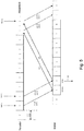
- the basic LTE downlink physical resource can thus be seen as a time-frequency grid as illustrated in
- each resource element corresponds to one OFDM subcarrier during one OFDM symbol interval.
- the uplink subframe has the same subcarrier spacing as the downlink and the same number of SC-FDMA symbols in the time domain as OFDM symbols in the downlink.
- Fig. 1 For normal cyclic prefix, one subframe consists of 14 OFDM symbols. The duration of each symbol is approximately 71.4 ⁇ s.
- resource allocation in LTE is typically described in terms of resource blocks, where a resource block corresponds to one slot (0.5 ms) in the time domain and 12 contiguous subcarriers in the frequency domain.
- a pair of two adjacent resource blocks in time direction (1.0 ms) is known as a resource block pair.
- Resource blocks are numbered in the frequency domain, starting with 0 from one end of the system bandwidth.
- Downlink transmissions are dynamically scheduled, i.e., in each subframe the base station transmits control information about which terminals data is transmitted to and upon which resource blocks the data is transmitted, in the current downlink subframe.
- CFI Control Format Indicator
- the downlink subframe also contains common reference symbols, which are known to the receiver and used for coherent demodulation of e.g. the control information.
- the reference symbols shown in the above Fig. 3 are the cell specific reference symbols (CRS) and are used to support multiple functions including fine time and frequency synchronization and channel estimation for certain transmission modes.
- CRS cell specific reference symbols
- PDCCH Physical Downlink Control Channel
- EPDCCH Enhanced PDCCH
- the PDCCH/EPDCCH is used to carry downlink control information (DCI) such as scheduling decisions and power-control commands. More specifically, the DCI includes:
- One PDCCH/EPDCCH carries one DCI message containing one of the groups of information listed above.
- Each scheduling message is transmitted on separate PDCCH/EPDCCH resources, and consequently there are typically multiple simultaneous PDCCH/EPDCCH transmissions within each subframe in each cell.
- link adaptation can be used, where the code rate of the PDCCH/EPDCCH is selected by adapting the resource usage for the PDCCH/EPDCCH, to match the radio-channel conditions.
- the LTE Rel-10 standard supports bandwidths larger than 20 MHz.
- One feature on LTE Rel-10 may be to assure backward compatibility with LTE Rel-8. This may also include spectrum compatibility. That would imply that an LTE Rel-10 carrier, wider than 20 MHz, may appear as a number of LTE carriers to an LTE Rel-8 terminal. Each such carrier can be referred to as a Component Carrier (CC).
- CC Component Carrier
- CA Carrier Aggregation
- PCell primary cell
- SCells secondary cells
- the number of aggregated CC as well as the bandwidth of the individual CC may be different for uplink and downlink.
- a symmetric configuration refers to the case where the number of CCs in downlink and uplink is the same whereas an asymmetric configuration refers to the case that the number of CCs is different.
- the number of CCs configured in a cell may be different from the number of CCs seen by a terminal: A terminal may for example support more downlink CCs than uplink CCs, even though the cell is configured with the same number of uplink and downlink CCs.
- a key feature of carrier aggregation is the ability to perform cross-carrier scheduling.
- This mechanism allows a (E)PDCCH on one CC to schedule data transmissions on another CC by means of a 3-bit Carrier Indicator Field (CIF) inserted at the beginning of the (E)PDCCH messages.
- CIF Carrier Indicator Field
- a UE For data transmissions on a given CC, a UE expects to receive scheduling messages on the (E)PDCCH on just one CC - either the same CC, or a different CC via cross-carrier scheduling; this mapping from (E)PDCCH to PDSCH is also configured semi-statically.
- a user equipment In the LTE system, a user equipment (UE) is notified by the network of downlink data transmission by the physical downlink control channel (PDCCH).
- PDCCH physical downlink control channel
- a UE Upon reception of a PDCCH in a particular subframe n, a UE is required to decode the corresponding physical downlink share channel (PDSCH) and to send ACK/NAK feedback in a subsequent subframe n + k. This is illustrated in Fig. 5 .
- the ACK/NAK feedback informs the eNodeB whether the corresponding PDSCH was decoded correctly. When the eNodeB detects an ACK feedback, it can proceed to send new data blocks to the UE.
- coded bits corresponding to the original data block will be retransmitted.
- the retransmission is based on repetition of previously sent coded bits, it is said to be operating in a Chase combining HARQ protocol.
- the retransmission contains coded bits unused in previous transmission attempts, it is said to be operating in an incremental redundancy HARQ protocol.
- the ACK/NAK feedback is sent by the UE using one of the two possible approaches depending on whether the UE is simultaneously transmitting a physical uplink shared channel (PUSCH):
- PUSCH physical uplink shared channel
- carrier sense multiple access with collision avoidance may be used for medium access.
- CCA clear channel assessment
- a transmission is initiated only if the channel is declared as Idle.
- Busy the transmission is essentially deferred until the channel is deemed to be Idle.
- LBT listen before talk
- station B may transmit the ACK frame back to station A with a delay of 16 ⁇ s.
- Such an ACK frame is transmitted by station B without performing an LBT operation.
- a station may be defer for a duration of 34 ⁇ s (referred to as DIFS) after the channel is observed to be occupied before assessing again whether the channel is occupied.
- DIFS duration of 34 ⁇ s
- a station that wishes to transmit may first perform a CCA by sensing the medium for a fixed duration, DIFS. If the medium is idle then the station assumes that it may take ownership of the medium and begin a frame exchange sequence. If the medium is busy, the station may wait for the medium to go idle, defer for DIFS, and wait for a further random backoff period.
- the PIFS may be used to gain priority access to the medium, and may be shorter than the DIFS duration. Among other cases, it may be used by STAs operating under PCF, to transmit Beacon Frames with priority.
- the PC may sense the medium. When the medium is determined to be idle for one PIFS period (generally 25 ⁇ s), the PC may transmit a Beacon frame containing the CF Parameter Set element and a delivery traffic indication message element.
- EN 301.893, v. 1.7.1 provides the following requirements and minimum behavior for the load-based clear channel assessment.
- the contention window size can be varied.
- the default size of the random backoff contention window is set to CWmin.
- the backoff contention window size CW is doubled whenever the station detects a collision of its transmission up to a limit, CWmax, set in the IEEE specs.
- CWmin a limit of the random backoff contention window size
- LAA Licensed assisted access
- LTE the spectrum used by LTE is dedicated to LTE. This has the advantage that an LTE system may not need to care about coexistence with other non-3GPP radio access technologies in the same spectrum and spectrum efficiency can be maximized.
- the spectrum allocated to LTE is limited which cannot meet the ever increasing demand for larger throughput from applications/services. Therefore, a new study item has been initiated in 3GPP on extending LTE to exploit unlicensed spectrum in addition to licensed spectrum.
- LAA SCell a secondary cell in unlicensed spectrum
- the LAA SCell may operate in DL-only mode or operate with both UL and DL traffic.
- the LTE nodes may operate in standalone mode in license-exempt channels without assistance from a licensed cell.
- Unlicensed spectrum may, by definition, be simultaneously used by multiple different technologies. Therefore, LAA as described above may needs to consider coexistence with other systems such as IEEE 802.11 (Wi-Fi).
- transmission on the SCell may conform to LBT protocols in order to avoid collisions and causing severe interference to on-going transmissions. This includes both performing LBT before commencing transmissions, and limiting the maximum duration of a single transmission burst.
- the maximum transmission burst duration is specified by country and region-specific regulations, for e.g., 4ms in Japan and 13ms in Europe according to EN 301.893.
- An example in the context of LAA is shown in Fig. 9 with different examples for the duration of a transmission burst on the LAA SCell constrained by a maximum allowed transmission duration of 4 ms.
- US 2005/122902 A1 relates to differentiation for quality of service of computer systems and computer devices, wherein a MAC layer protocol sets a backoff period for packet transmissions according to a contention window.
- the devices can be configured as wireless mobile devices which wirelessly communicate with different types of wireless networks.
- a method provides updates to the contention window that alters the contention window according to a required quality of service for each device or for a predetermined data flow.
- the method further provides an adaptive method for determining a contention window which is desirable because the size limits on the contention window affects WLAN system efficiency as a function of the number of transmissions attempted over a channel. Depending on the number of devices at any given time and the potential for collisions, the proper contention window for efficient transmission can change over time.
- US 2013/235721 A1 relates to a mesh network with a plurality of nodes which may include one or more software applications producing and/or gathering data for transmission.
- network load management includes techniques to size contention windows associated with one or more applications.
- RF transmission retry management includes an algorithm and/or techniques to resize contention windows based in part on input including representations of link quality and traffic density.
- a contention window sizing algorithm calculates a size of a contention window for each of the applications on the node which may then be applied to transmission of data or instructions created by the applications on the node. Then the transmission retry algorithm resizes the contention window by utilizing data indicating an RF link quality between neighboring nodes and data indicating traffic density and determining if contention window(s) should be changed.
- this object is achieved by providing a method performed by a transmitting node for performing data transmissions to at least one receiving node on a radio channel in a wireless communications network.
- the transmitting node sets at least two contention window sizes, wherein the at least two contention window sizes are separately determined based on information associated with the least one receiving node.
- the transmitting node defers a first transmission of data to the at least one receiving node for a first period of observation of the radio channel determined by a first contention window size of the at least two contention window sizes.
- the transmitting node further defers at least one second transmission of data to the at least one receiving node for at least one second period of observation of the radio channel determined by at least a second contention window size of the at least two contention window sizes. Furthermore, the transmitting node performs the first or the at least one second transmission of data to the at least one receiving node when an outcome of the first or the at least second periods of observation of the radio channel, respectively, is that the radio channel is idle.
- this object is achieved by a transmitting node for performing data transmissions to at least one receiving node on a radio channel in a wireless communications network.
- the transmitting node is configured to set at least two contention window sizes, wherein the at least two contention window sizes are separately determined based on information associated with the least one receiving node.
- the transmitting node is also configured to defer a first transmission of data to the at least one receiving node for a first period of observation of the radio channel determined by a first contention window size of the at least two contention window sizes.
- the transmitting node is configured to also defer at least one second transmission of data to the at least one receiving node for at least one second period of observation of the radio channel determined by at least a second contention window size of the at least two contention window sizes.
- the transmitting node is further configured to perform the first or the at least one second transmission of data to the at least one receiving node when an outcome of the first or the at least second periods of observation of the radio channel, respectively, is that the radio channel is idle.
- the object is achieved by a computer program, comprising instructions which, when executed on at least one processor, cause the at least one processor to carry out the method described above.
- the object is achieved by a carrier containing the computer program described above, wherein the carrier is one of an electronic signal, optical signal, radio signal, or computer readable storage medium.
- the transmission node By separately determining and setting at least two contention window sizes based on information associated with the least one receiving node, e.g. maintaining multiple contention window sizes for multiple intended receivers, the transmission node is enabled to adapt its transmissions in view of different number of contending neighboring nodes, i.e. neighbors, in the vicinities of the intended receivers, i.e. at least one receiving node. In other words, the transmitting node is enabled to perform improved transmissions towards the intended receivers considering the intended receivers' channel conditions and interference situations.
- this may ensure a fair coexistence between co-channel LAA and Wi-Fi and result in that unnecessarily long medium access delay may be avoided for the intended receivers that experience good SINR conditions, e.g. receivers being positioned close to the transmitting node.
- the performance of the wireless communications network is improved.
- Radio network node In some embodiments the non-limiting term radio network node is more commonly used and it refers to any type of network node serving UE and/or connected to other network node or network element or any radio node from where UE receives signal.
- radio network nodes are Node B, base station (BS), multi-standard radio (MSR) radio node such as MSR BS, eNode B, network controller, radio network controller (RNC), base station controller, relay, donor node controlling relay, base transceiver station (BTS), access point (AP), transmission points, transmission nodes, RRU, RRH, nodes in distributed antenna system (DAS) etc.
- BS base station
- MSR multi-standard radio
- RNC radio network controller
- BTS base transceiver station
- AP access point
- DAS distributed antenna system
- Network node In some embodiments a more general term "network node” is used and it can correspond to any type of radio network node or any network node, which communicates with at least a radio network node. Examples of network node are any radio network node stated above, core network node (e.g. MSC, MME etc.), O&M, OSS, SON, positioning node (e.g. E-SMLC), MDT etc.
- UE user equipment
- UE user equipment
- target device device to device UE
- machine type UE or UE capable of machine to machine communication PDA, iPAD, Tablet
- mobile terminals smart phone, laptop embedded equipped (LEE), laptop mounted equipment (LME), USB dongles, etc.
- LEE laptop embedded equipped
- LME laptop mounted equipment
- LBT systems adapt the contention window size for the transmitter. Such restriction is not optimal when a transmitter is able to transmit to several receivers at different distances and different number of neighbors. For instance, a WiFi transmitter doubles its contention window size if it does not receive the ACK at the expected time. The ACK however is related to the transmission to a given receiver. But the contention window size update is transmitter-specific and thus its increase due to a single receiver failing affects the performance of all possible receivers of the same transmitter.
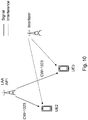
- UE3 is far away from its serving LAA Access Point, AP1, and will experience severe interference from an interferer.
- LAA AP1 may increase its contention window size up to the maximum size because of continued frame errors.
- AP1 may wish to transmit to UE2 instead of continuing performing transmission to UE3 based on factors such latency, quality of services and contractual requirements.
- UE2 is close to its serving AP 1 and far away from an interfering node so that expected SINR can be high enough not to cause any frame error even without applying a large random backoff.
- embodiments herein focuses on the LBT phase of a load-based OFDM system, and are designed to ensure fairer coexistence with other radio access technologies such as Wi-Fi while also satisfying EN 301.893 regulations.
- Fig. 11 depicts an example of a wireless communications network 100, sometimes also referred to as a cellular radio system, cellular network or wireless communications system, in which embodiments herein may be implemented.
- the wireless communications network 100 may for example be a network such as a Long-Term Evolution (LTE), e.g.
- LTE Long-Term Evolution
- LTE Frequency Division Duplex (FDD), LTE Time Division Duplex (TDD), LTE Half-Duplex Frequency Division Duplex (HD-FDD), LTE operating in an unlicensed band, Wideband Code Division Multiple Access (WCDMA), Universal Terrestrial Radio Access (UTRA) TDD, Global System for Mobile communications (GSM) network, GSM/Enhanced Data Rate for GSM Evolution (EDGE) Radio Access Network (GERAN) network, Ultra-Mobile Broadband (UMB), EDGE network, network comprising of any combination of Radio Access Technologies (RATs) such as e.g.
- RATs Radio Access Technologies
- Multi-Standard Radio (MSR) base stations multi-RAT base stations etc., any 3rd Generation Partnership Project (3GPP) cellular network, WiFi networks, Worldwide Interoperability for Microwave Access (WiMax), 5G system or any cellular network or system.
- 3GPP LTE 3rd Generation Partnership Project LTE
- WiFi Wireless Fidelity
- WiMax Worldwide Interoperability for Microwave Access
- the wireless communications network 100 comprises a plurality of network nodes whereof the network node 110 is depicted in Fig. 11 .
- the network node 110 may be a transmission point such as a radio base station, for example an eNB, an eNodeB, or an Home Node B, an Home eNode B or any other network node capable to serve a wireless device, such as a user equipment or a machine type communication device in a wireless communications network.
- the wireless communications network 100 covers a geographical area which is divided into cell areas, wherein each cell area is served by a network node, although, one network node may serve one or several cells.
- the network node 110 serves a first cell 131 or primary cell 131.
- the primary cell 131 is typically in licensed spectrum.
- the network node 110 also serves a second cell 132, licensed-assisted access cell 132, also referred to herein as licensed-assisted access secondary cell 132, as defined above.
- the licensed-assisted access cell 132 is in unlicensed spectrum.
- the primary cell 131 and the licensed-assisted access cell 132 are used for communication between the network node 110 and wireless device 120.
- the network node 100 may be of different classes, such as, e.g., macro eNodeB, home eNodeB or pico base station, based on transmission power and thereby also cell size.
- wireless communications network 100 may comprise more cells similar to the first cell 131 and the second cell 132, served by their respective network node. This is not depicted in Fig. 14 for the sake of simplicity.
- the network node 110 may support one or several communication technologies, and its name may depend on the technology and terminology used. In 3GPP LTE, the network node 110, which may be referred to as eNodeBs or even eNBs, may be directly connected to one or more core networks.
- the wireless device 120 also referred to herein as a user equipment or UE is located in the wireless communication network 100.
- the wireless device 120 may e.g. be a user equipment, a mobile terminal or a wireless terminal, a mobile phone, a computer such as e.g. a laptop, a Personal Digital Assistants (PDAs) or a tablet computer, sometimes referred to as a surf plate, with wireless capability, or any other radio network units capable to communicate over a radio link in a wireless communications network.
- PDAs Personal Digital Assistants
- a tablet computer sometimes referred to as a surf plate
- the term user equipment used in this document also covers other wireless devices such as Machine to machine (M2M) devices, even though they do not have any user.
- M2M Machine to machine
- the wireless devices 120 is configured to communicate within the wireless communications network 100 with the network node 110 over a first radio link 141 in the primary cell 131, and over a second radio link 142 in the licensed-assisted access cell 132.
- any of the network node 110 and the wireless device 120 may be referred to herein as a transmitting node. Any of the network node 110 and the wireless device 120 may be referred to herein as a receiving node. It should be noted that any reference herein to a UE is understood to apply to a wireless devices such as the wireless device 120. Any reference herein to a eNB is understood to apply to a network node such as the network node 110. Any reference herein to a transmitting node or transmitter is understood to apply equally to a network node 110 or a wireless device 120. Any reference herein to a receiving node or receiver is understood to apply equally to a network node 110 or a wireless device 120.
- the embodiments herein may be described as performing a receiver dependent contention window adaptation defined for load-based LBT systems operating in unlicensed bands when a transmitter intends to transmit data to multiple receivers.
- the contention window chosen at each transmitter should be receiver specific in order to optimally reflect different geographical distance or long-term channel conditions from a transmitter.
- the contention window, CW from which a random back-off counter may be drawn for a new LBT attempt is represented by CW, so that the counter drawn falls within the time interval [0, CW].
- a physical intended receiver may be treated as a multitude of virtual intended receivers when said physical intended receiver has data with different quality of service, importance or delay tolerance classes.
- multiple contention windows corresponding to multiple physical or virtual intended receivers are handled in one transmission opportunity or instance.
- Fig. 12 illustrates an example of actions or operations which may be taken by transmitting node 110, 120.
- the least one receiving node 120, 110 may comprises two or more receiving nodes in the wireless communications network 100.
- the transmitting node 110, 120 may also continuously monitor the radio channel.
- the method may comprise the following actions.
- the transmitting node 110, 120 sets at least two contention window sizes, wherein the at least two contention window sizes are separately determined based on information associated with the least one receiving node 120, 110. It should be noted that this may also be described as the transmitting node 110, 120 setting at least two counters to values selected from at least two time intervals, wherein the at least two time intervals are separately determined based on information associated with the least one receiving node.
- the at least two time intervals correspond to the at least two contention window sizes.
- the transmitting node 110, 120 may determine the first contention window size based on a priority of a first class of services of at least two classes of services with different priorities in the at least one receiving node 120, 110, and determine the at least second contention window size based on a priority of at least one second class of services of the at least two classes of services with different priorities in the at least one receiving node 120, 110. This may, for example, be performed when the least one receiving node 120, 110 is a single receiving node having at least two classes of services with different priorities.
- the information associated with the least one receiving node 120, 110 is one or more of:
- the transmitting node 110, 120 may determine a joint contention window size based on the first and at least second contention window size to be used when the transmitting node 110, 120 capable to serve more than one receiving node and schedule more than one receiving node during a single transmission instance. In some embodiments, the transmitting node 110, 120 may also obtain the information associated with the least one receiving node 120, 110 from another node in the wireless communications network 100.
- the transmitting node 110, 120 After setting the at least two contention window sizes in Action 1201, the transmitting node 110, 120 defers a first transmission of data to the at least one receiving node 120, 110 for a first period of observation of the radio channel determined by a first contention window size of the at least two contention window sizes. In case of using the counter terminology in Action 1201, this may be described as the transmitting node 110, 120 deferring a first transmission of data to the at least one receiving node for a first period of observation of the radio channel determined by a first counter of the at least two counters.
- the transmitting node 110, 120 also defers at least one second transmission of data to the at least one receiving node 120, 110 for at least one second period of observation of the radio channel determined by at least a second contention window size of the at least two contention window sizes. Also here, in case of using the counter terminology in Action 1201, this may be described as the transmitting node 110, 120 deferring at least one second transmission of data to the at least one receiving node for at least one second period of observation of the radio channel determined by at least one second counter of the at least two counters.
- the transmitting node 110, 120 then performs the first or the at least one second transmission of data to the at least one receiving node 120, 110 when an outcome of the first or the at least second periods of observation of the radio channel, respectively, is that the radio channel is idle.
- the transmitting node 110, 120 may adapt each of the first and at least second contention window size separately based on the information associated with the least one receiving node 120, 110. In some embodiments, the transmitting node 110, 120 may adapt by increasing at least one of the first and at least second contention window size when the corresponding transmission of data to the at
- the transmitting node 110, 120 may adapt by increasing the at least one of the first and at least second contention window size in increments up to a determined maximum contention window size. In some embodiments, the transmitting node 110, 120 may adapt by decreasing at least one of the first and at least second contention window size when the corresponding transmission of data to the at least one receiving node 120, 110 is determined to be successful. In some embodiments, the transmitting node 110, 120 may adapt by resetting at least one of the first and at least second contention window size to a determined starting contention window size when the corresponding transmission of data to the at least one receiving node 120, 110 is determined to be successful.
- the transmitting node 110, 120 may adapt by increasing and/or decreasing the rate of change separately for each of the first and at least second contention window size based on the information associated with the least one receiving node 120, 110. In some embodiments, the transmitting node 110, 120 may adapt according to a Listen Before Talk, LBT, algorithm.
- different contention window sizes may be used at the same transmitter, e.g. the transmitting node 110, 120. This may also be referred to herein as having receiver dependent contention windows, CWs.
- Fig. 13 is an example describing the high level procedure of receiver dependent CW adjustment. It should be noted that the Actions 1301-1304 described with reference to Fig. 13 illustrate embodiments of the Actions 1201-1204 described above with reference to Fig. 12 .
- a transmitter i e.g. an AP, may maintain a contention window size for each of the associated receivers, i.e. at least one receiving node 120, 110.
- the transmitter i schedules data intended for a receiver k .
- the transmitter i randomly chooses N from a given contention widow size CW i ⁇ k .
- CW i ⁇ k is a receiver dependent parameter intended for receiver k associated with a serving AP i .
- the transmitter i senses the channel.
- the transmitter i transmits the data according to LBT.
- the contention window size assigned to the receiver may depend on the type of the receiver. According to another aspect, the contention window size assigned to the receiver may depend on the service requirements for the receivers. According to yet another aspect, the contention window size of a receiver may be retrieved from a centralized management entity.
- the contention window size for a receiver may be reconfigured.
- the transmitter may double the contention window sizes of all its associated receivers.
- the transmitter may increase the contention window sizes of all its associated receivers by the same amount.
- the contention window size for each associated receiver may be adapted separately by the transmitter. This may also be referred to herein as having receiver dependent contention window, CW, adjustment.
- An example of this second embodiment is illustrated in Fig. 14 , wherein the contention window sizes are adapted based on observed successes or failures of previous transmissions.
- the Actions 1401-1406 described with reference to Fig. 14 illustrate embodiments of the Actions 1201-1205 described above with reference to Fig. 12 .
- Actions 1401-1404 correspond to Actions 1301-1304 described with reference to Fig. 13 , but further comprise Actions 1405-1406.
- CW i ⁇ k may be reset by the transmitter i of a specific value CWmin according to the LBT algorithm in use.
- the CW i ⁇ k may be increased by the transmitter i , up to a limit of CWmax, according to the specific rules in determined LBT protocols of the system.
- the contention window size CW i ⁇ k is doubled if one or more previous transmissions result in errors.
- the rate of increase of contention windows between CWmin and CWmax used for each receiver may be different.
- the contention window for UE p may be doubled if one or more previous transmissions results in errors whereas the contention window for UE q may be tripled if one or more previous transmissions results in errors.
- This may generalized by using different sets of values for the contention windows for different UEs. Therefore, in general, for the k :th UE, the transmitter may use a set of contention windows, CW i ⁇ k ⁇ ⁇ CWmin, CW i ⁇ k (1), CW i ⁇ k (2), ..., CWmax ⁇ .
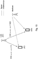
- LAA AP1 e.g. a transmitting node 110
- LAA AP1 differentiates CW according to the channel conditions of the UE's, e.g. the at least one receiving node 120.
- LAA AP1 uses a shorter contention windows size CW1 LAA AP1 ⁇ UE2 (also denoted CW1 ⁇ 2 ) for a cell center UE2 than the contention windows size CW1 LAA AP1 ⁇ UE3 (also denoted CW1 ⁇ 3) for a cell edge UE3.
- a cell center UE2 is closer to the LAA AP1 that a cell edge UE3.
- the CWmin and CWmax parameters may be receiver-dependent parameters rather than transmitter or traffic type dependent, such as, for example, for the standard IEEE 802.11. More specifically, each transmitter may use long-term statistical information, to adaptively determine or derive optimized CWmin and CWmax parameter settings. This may also be referred to herein as having receiver dependent CWmin and CWmax adjustment.
- a pair of CWmin and CWmax for UE j may be selected. For example, if assumed that LAA AP i is to set CWmin(i,j) and CWmax(i,j) for its associated UE j. Then, a table may be predetermined and may be used by the AP i in order to find a proper CWmin(i,j) and CWmax(i,j).
- Table 1 below illustrates an example of such a table that, for example, each LAA AP may comprise or have access to for determining CWmin(i,j) and CWmax(i,j) when metric X is used for the long-term statistical information.
- Table 1 is an illustrative example of receiver dependent CWmin and CWmax adaptation based on long-term statistical information.
- one of CWmin,k and CWmax,k may be fixed regardless of k so that each AP adaptively may change either the contention window's lower or its upper limit.
- the metrics used may comprise one or more of:
- an intended receiver may have multiple classes of services with different priorities. This may also be referred to herein as having receiver dependent contention window, CW, adjustment for multiple service classes.
- an intended receiver j may have two services, one of type m and one of type n.
- a receiver dependent CWi ⁇ j at LAA AP i may be further specified to also reflect or indicate the priority of the two types of services m and n, e.g. the service type m have CWi ⁇ j (m) and the service type n may have CWi ⁇ j (n).
- each LAA AP i may configure the contention windows such that CWi ⁇ j (m) ⁇ CWi ⁇ j (n).
- CWmin(i,j) and CWmax(i,j) may also be service specific.
- receiver dependent CW adjustment may also be performed as downlink multiplexing both in time and frequency domain is supported by the transmitter. This may also be referred to herein as having receiver dependent contention window, CW, adjustment for multiple users.
- An example of such a multiplexing transmitter is an LTE eNB, where more than one receiver may be served by, or associated with, the same LAA AP and be scheduled during a single transmission opportunity.
- a joint contention window, CW JT may be used which may be a function of all scheduled UE's CWs.
- the weights may take into account or be at least partly based on the amount of resource block allocations.
- nj and nk may represent the number of allocated resource blocks to each UE at a given transmission opportunity.
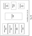
- the embodiments herein may be implemented through one or more processors, such as a processor 1608 in the transmitting node 110, 120 depicted in Fig. 16 , together with computer program code for performing the functions and actions of the embodiments herein.
- the program code mentioned above may also be provided as a computer program product, for instance in the form of a data carrier carrying computer program code for performing the embodiments herein when being loaded into the transmitting node 110, 120.
- One such carrier may be in the form of a CD ROM disc. It is however feasible with other data carriers such as a memory stick.
- the computer program code may furthermore be provided as pure program code on a server and downloaded to the transmitting node 110, 120.
- the transmitting node 110, 120 may further comprise a memory 1609 comprising one or more memory units.
- the memory 1609 is arranged to be used to store obtained information, store data, configurations, scheduling, and applications etc. to perform the methods herein when being executed in transmitting node 110, 120.
- the transmitting node 110, 120 may receive information through a receiving port 1610.
- the receiving port 1610 may be, for example, connected to the two or more antennas in the transmitting node 110, 120.
- the transmitting node 110, 120 may receive information from another structure in the wireless communications network 100 through the receiving port 1610. Since the receiving port 1610 may be in communication with the processor 1608, the receiving port 1608 may then send the received information to the processor 1610.
- the receiving port 1608 may also be configured to receive other information.
- the processor 1608 in the transmitting node 110, 120 may be further configured to transmit or send information through a sending port 1611, which may be in communication with the processor 1608 and the memory 1609.
- the transmitting node is configured to set at least two contention window sizes, wherein the at least two contention window sizes are separately determined based on information associated with the least one receiving node 120, 110.
- the transmitting node may be configured to set at least two counters to values selected from at least two time intervals, wherein the at least two time intervals are separately determined based on information associated with the least one receiving node 120, 110.
- the transmitting node 110, 120 is configured to perform this action, e.g. by means of a setting module 1601 within the transmitting node.
- the setting module 1601 may be a processor of the transmitting node, or an application running on such processor.
- the transmitting node 110, 120 is also configured to defer a first transmission of data to the at least one receiving node 120, 110 for a first period of observation of the radio channel determined by a first counter of the at least two counters.
- the transmitting node 110, 120 may also be configured to defer a first transmission of data to the at least one receiving node 120, 110 for a first period of observation of the radio channel determined by a first contention window size of the at least two contention window sizes.
- the transmitting node 110, 120 may also be configured to defer at least one second transmission of data to the at least one receiving node 120, 110 for at least one second period of observation of the radio channel determined by at least one second counter of the at least two counters.
- the transmitting node 110, 120 may also be configured to defer at least one second transmission of data to the at least one receiving node 120, 110 for at least one second period of observation of the radio channel determined by at least a second contention window size of the at least two contention window sizes.
- the transmitting node 110, 120 is configured to perform these actions, e.g. by means of a deferring module 1602 within the transmitting node 110, 120.
- the deferring module 1602 may be a processor of the transmitting node 110, 120, or an application running on such processor.
- the transmitting node 110, 120 is configured to perform the first or the at least one second transmission of data to the at least one receiving node 120, 110 when an outcome of the first or the at least second periods of observation of the radio channel, respectively, is that the radio channel is idle.
- the transmitting node 110, 120 is configured to perform this action, e.g. by means of a performing or transmitting module 1603 within the transmitting node 110, 120.
- the performing module or transmitting module 1603 may be a processor of the transmitting node 110, 120, or an application running on such processor.
- the transmitting node 110, 120 may be further configured to determine the first contention window size based on a priority of a first class of services of at least two classes of services with different priorities in the at least one receiving node 120, 110, and determine the at least one second contention window size based on a priority of at least one second class of services of the at least two classes of services with different priorities in the at least one receiving node 120, 110.
- the least one receiving node 120, 110 may be a single receiving node having at least two classes of services with different priorities.
- the information associated with the least one receiving node 120, 110 is one or more of: the types of the least one receiving node 120, 110; the service requirements of the least one receiving node 120, 110; observed successes and/or failures of previously performed data transmissions to the least one receiving node 120, 110; statistical information of the least one receiving node 120, 110 (such as, e.g. long term Signal-to-Noise Ratio, SINR, distribution, Received Signal Strength Indicator, RSSI, histogram based on measurement reports of the least one receiving node 120, 110, frame error or retransmission probability experienced by the least one receiving node 120, 110); and the number of the least one receiving node 120, 110 having transmissions of data scheduled at the same time.
- the transmitting node 110, 120 may be further configured to adapt each of the first and at least second contention window size separately based on the information associated with the least one receiving node 120, 110.
- the transmitting node 110, 120 may be further configured to adapt each of the at least two time intervals separately based on the information associated with the least one receiving node 120, 110.
- the transmitting node 110, 120 is configured to perform this action, e.g. by means of a adapting module 1604 within the transmitting node 110, 120.
- the adapting module 1604 may be a processor of the transmitting node 110, 120, or an application running on such processor.
- the transmitting node 110, 120 may be further configured to perform the adaptation by increasing at least one of the first and at least second contention window size when the corresponding transmission of data to the at least one receiving node 120, 110 is determined to be unsuccessful.
- the transmitting node 110, 120 may be further configured to perform the adaptation by increasing at least one time interval of the at least two time intervals when the corresponding transmission of data to the at least one receiving node 120, 110 is determined to be unsuccessful or has failed.
- the transmitting node 110, 120 may be further configured to perform the adaptation by increasing at least one of the first and at least second contention window size in increments up to a determined maximum contention window size time interval. In other words, the transmitting node 110, 120 may be further configured to perform the adaptation by increasing the at least one time interval of the at least two time intervals in increments up to a determined maximum time interval.
- the transmitting node 110, 120 may be further configured to perform the adaptation by decreasing at least one of the first and at least second contention window size when the corresponding transmission of data to the at least one receiving node 120, 110 is determined to be successful. In other words, the transmitting node 110, 120 may be further configured to perform the adaptation by decreasing at least one time interval of the at least two time intervals when the corresponding transmission of data to the at least one receiving node 120, 110 is determined to be successful.
- the transmitting node 110, 120 may be further configured to perform the adaptation by resetting at least one of the first and at least second contention window size to a determined starting contention window size when the corresponding transmission of data to the at least one receiving node 120, 110 is determined to be successful.
- the transmitting node 110, 120 may be further configured to perform the adaptation by resetting at least one time interval of the at least two time intervals to a determined starting time interval when the corresponding transmission of data to the at least one receiving node 120, 110 is determined to be successful.
- the transmitting node 110, 120 may be further configured to perform the adaptation by increasing and/or decreasing the rate of change separately for each of the first and at least second contention window size based on the information associated with the least one receiving node 120, 110.
- the transmitting node 110, 120 may be further configured to perform the adaptation by increasing and/or decreasing the rate of change separately for each of the at least two time intervals based on the information associated with the least one receiving node 120, 110.
- the transmitting node 110, 120 may be further configured to adapt each of the first and at least second contention window size according to a Listen Before Talk, LBT, algorithm. In other words, the transmitting node 110, 120 may be further configured to adapt each of the at least two time intervals according to a Listen Before Talk, LBT, algorithm.
- the transmitting node 110, 120 may be further configured to determine a joint contention window size based on the first and at least second contention window size to be used when the transmitting node 110, 120 110, 120 is capable to serve more than one receiving node 120, 110 and schedule more than one receiving node 120, 110 during a single transmission instance.
- the transmitting node 110, 120 may be further configured to determine a joint time interval based on the at least two time intervals to be used by all of the at least two counters when the transmitting node 110, 120 capable to serve more than one receiving node 120, 110 and schedule more than one receiving node 120, 110 during a single transmission instance.
- the transmitting node 110, 120 may be further configured to obtain the information associated with the least one receiving node 120, 110 from another node in the wireless communications network, such as, e.g. a centralized management node.
- the values of the counters are values for idle periods of observation of a radio channel.
- the radio channel is wherein data may be transmitted by the radio node 101.
- the idle periods of observation may be, for example, one or more CCAs.
- the transmitting node 110, 120 may comprise an interface unit (not shown) to facilitate communications between the transmitting node 110, 120 and other nodes or devices, e.g., any of the network node 110 and the wireless device 120.
- the interface may, for example, include a transceiver configured to transmit and receive radio signals over an air interface in accordance with a suitable standard.
- Embodiments herein may comprise an enhanced load-based clear channel assessment.
- the setting module 1601, the deferring module 1602, the performing module 1603, and the adapting module 1604 described above may refer to a combination of analog and digital modules, and/or one or more processors configured with software and/or firmware, e.g., stored in memory, that, when executed by the one or more processors such as the processor 1608, perform as described above.
- processors as well as the other digital hardware, may be included in a single Application-Specific Integrated Circuit (ASIC), or several processors and various digital hardware may be distributed among several separate components, whether individually packaged or assembled into a System-on-a-Chip (SoC).
- ASIC Application-Specific Integrated Circuit
- SoC System-on-a-Chip
- the different modules 1601-1604 described above may be implemented as one or more applications running on one or more processors such as the processor 1608.
- the methods according to the embodiments described herein for the transmitting node 110, 120 may be implemented by means of a computer program product, comprising instructions, i.e., software code portions, which, when executed on at least one processor, cause the at least one processor to carry out the actions described herein, as performed by the transmitting node 110, 120.
- the computer program product may be stored on a computer-readable storage medium.
- the computer-readable storage medium, having stored there on the computer program may comprise instructions which, when executed on at least one processor, cause the at least one processor to carry out the actions described herein, as performed by the transmitting node 110, 120.
- the computer-readable storage medium may be a non-transitory computer-readable storage medium, such as a CD ROM disc, or a memory stick.
- the computer program product may be stored on a carrier containing the computer program just described, wherein the carrier is one of an electronic signal, optical signal, radio signal, or the computer-readable storage medium, as described above.
Claims (15)
- Procédé réalisé par un nœud de transmission (110 ; 120) destiné à réaliser des transmissions de données à au moins un nœud de réception (120 ; 110) sur un canal radio dans un réseau de communications sans fil (100), le procédé comprenant
l'établissement (1201) d'au moins deux tailles de fenêtre de contention, les au moins deux tailles de fenêtre de contention étant déterminées séparément sur la base d'informations associées à l'au moins un nœud de réception (120 ; 110) ;
le report (1202) d'une première transmission de données à l'au moins un nœud de réception (120 ; 110) pendant une première période d'observation du canal radio déterminée par une première taille de fenêtre de contention des au moins deux tailles de fenêtre de contention ;
le report (1203) d'au moins une deuxième transmission de données à l'au moins un nœud de réception (120 ; 110) pendant au moins une deuxième période d'observation du canal radio déterminée par au moins une deuxième taille de fenêtre de contention des au moins deux tailles de fenêtre de contention ; et
la réalisation (1204) de la première ou de l'au moins une deuxième transmission de données à l'au moins un nœud de réception (120 ; 110) lorsqu'un résultat de la première ou de l'au moins deuxième période d'observation du canal radio, respectivement, indique que le canal radio est inactif ; caractérisé en ce que le procédé comprenant en outre
la détermination, dans un cas où le nœud de transmission (110 ; 120) sert plus d'un nœud de réception et planifie les plus d'un nœud de réception pendant une seule opportunité de transmission, d'une taille de fenêtre de contention jointe, la taille de fenêtre de contention jointe étant fonction de tailles de fenêtre de contention de l'ensemble de nœuds de réception planifiés ; et
l'utilisation de la taille de fenêtre de contention jointe déterminée dans ce cas. - Procédé selon la revendication 1, dans lequel la première taille de fenêtre de contention est déterminée sur la base d'une priorité d'une première classe de services d'au moins deux classes de services avec des priorités différentes dans l'au moins un nœud de réception (120 ; 110), et l'au moins deuxième taille de fenêtre de contention est déterminée que la base d'une priorité d'au moins une deuxième classe de services des au moins deux classes de services avec des priorités différentes dans l'au moins un nœud de réception (120 ; 110).
- Procédé selon la revendication 1 ou 2, dans lequel les informations associées à l'au moins un nœud de réception (120 ; 110) sont au moins l'un des éléments suivants :- les types de l'au moins un nœud de réception (120 ; 110) ;- les exigences de service de l'au moins un nœud de réception (120 ; 110) ;- les réussites et/ou échecs observés de transmissions de données réalisées auparavant vers l'au moins un nœud de réception (120 ; 110) ;- des informations statistiques de l'au moins un nœud de réception (120 ; 110) ; et- le nombre de l'au moins un nœud de réception (120 ; 110) ayant des transmissions de données planifiées au même moment.
- Procédé selon l'une quelconque des revendications 1 à 3, comprenant en outre
l'adaptation (1205) de chacune des première et au moins deuxième tailles de fenêtre de contention séparément sur la base des informations associées à l'au moins un nœud de réception (120 ; 110). - Procédé selon la revendication 4, dans lequel l'adaptation (1205) comprend en outre l'augmentation d'au moins l'une de la première et de l'au moins deuxième taille de fenêtre de contention lorsque la transmission correspondante de données à l'au moins un nœud de réception (120 ; 110) est déterminée comme non réussie.
- Procédé selon la revendication 5, dans lequel l'adaptation (1205) comprend en outre l'augmentation de l'au moins une de la première et de l'au moins deuxième taille de fenêtre de contention par incréments jusqu'à une taille de fenêtre de contention maximale déterminée.
- Procédé selon l'une quelconque des revendications 1 à 6, lequel l'adaptation (1205) comprend en outre la diminution d'au moins l'une de la première et de l'au moins deuxième taille de fenêtre de contention lorsque la transmission correspondante de données à l'au moins un nœud de réception (120 ; 110) est déterminée comme réussie.
- Procédé selon la revendication 7, dans lequel l'adaptation (1205) comprend en outre la réinitialisation d'au moins l'une de la première et de l'au moins deuxième taille de fenêtre de contention à une taille de fenêtre de contention de départ déterminée lorsque la transmission correspondante de données à l'au moins un nœud de réception (120 ; 110) est déterminée comme réussie.
- Procédé selon l'une quelconque des revendications 4 à 8, dans lequel l'adaptation (1205) comprend en outre l'augmentation et/ou la diminution de la cadence de changement séparément pour chacune des première et au moins deuxième tailles de fenêtre de contention sur la base des informations associées à l'au moins un nœud de réception (120 ; 110).
- Procédé selon l'une quelconque des revendications 4 à 9, dans lequel l'adaptation (1205) est réalisée selon un algorithme d'écoute avant transmission, LBT.
- Procédé selon l'une quelconque des revendications 1 à 10, comprenant en outre l'obtention des informations associées à l'au moins un nœud de réception (120 ; 110) depuis un autre nœud dans le réseau de communications sans fil (100).
- Nœud de transmission (110 ; 120) destiné à réaliser des transmissions de données à au moins un nœud de réception (120 ; 110) sur un canal radio dans un réseau de communications sans fil (100), le nœud de transmission (110 ; 120) étant configuré pour :établir au moins deux tailles de fenêtre de contention, les au moins deux tailles de fenêtre de contention étant déterminées séparément sur la base d'informations associées à l'au moins un nœud de réception (120 ; 110),reporter une première transmission de données à l'au moins un nœud de réception (120 ; 110) pendant une première période d'observation du canal radio déterminée par une première taille de fenêtre de contention des au moins deux tailles de fenêtre de contention,reporter au moins une deuxième transmission de données à l'au moins un nœud de réception (120 ; 110) pendant au moins une deuxième période d'observation du canal radio déterminée par au moins une deuxième taille de fenêtre de contention des au moins deux tailles de fenêtre de contention, etréaliser la première ou l'au moins une deuxième transmission de données à l'au moins un nœud de réception (120 ; 110) lorsqu'un résultat de la première ou de l'au moins deuxième période d'observation du canal radio, respectivement, indique que le canal radio est inactif ;caractérisé en ce que le nœud de transmission (110 ; 120) est en outre configuré pourdéterminer, dans un cas où le nœud de transmission (110 ; 120) sert plus d'un nœud de réception et planifie les plus d'un nœud de réception pendant une seule opportunité de transmission, une taille de fenêtre de contention jointe, la taille de fenêtre de contention jointe étant fonction de tailles de fenêtre de contention de l'ensemble de nœuds de réception planifiés ; etutiliser la taille de fenêtre de contention jointe déterminée dans ce cas.
- Nœud de transmission(110 ; 120) selon la revendication 12, le nœud de transmission (110 ; 120) étant en outre configuré pour déterminer la première taille de fenêtre de contention sur la base d'une priorité d'une première classe de services d'au moins deux classes de services avec des priorités différentes dans l'au moins un nœud de réception (120 ; 110), et déterminer l'au moins une deuxième taille de fenêtre de contention sur la base d'une priorité d'au moins une deuxième classe de services des au moins deux classes de services avec des priorités différentes dans l'au moins un nœud de réception (120 ; 110).
- Produit de programme informatique, comprenant des instructions qui, lorsqu'elles sont exécutées sur au moins un processeur (1608), amènent l'au moins un processeur (1608) à mettre en œuvre le procédé selon l'une quelconque des revendications 1 à 11.
- Support contenant le produit de programme informatique selon la revendication 14, le support étant l'un d'un signal électronique, d'un signal optique, d'un signal radio ou d'un support de stockage lisible par ordinateur.
Priority Applications (1)
| Application Number | Priority Date | Filing Date | Title |
|---|---|---|---|
| PL16729082T PL3320743T3 (pl) | 2015-07-06 | 2016-05-10 | Węzeł nadawczy i sposób w tym węźle do wykonywania transmisji danych do co najmniej jednego węzła odbiorczego na kanale radiowym w bezprzewodowej sieci telekomunikacyjnej |
Applications Claiming Priority (2)
| Application Number | Priority Date | Filing Date | Title |
|---|---|---|---|
| US201562188883P | 2015-07-06 | 2015-07-06 | |
| PCT/SE2016/050416 WO2017007391A1 (fr) | 2015-07-06 | 2016-05-10 | Nœud d'émission et procédé en son sein destiné à la transmission de données à au moins un nœud de réception sur une voie radioélectrique d'un réseau de communication sans fil |
Publications (2)
| Publication Number | Publication Date |
|---|---|
| EP3320743A1 EP3320743A1 (fr) | 2018-05-16 |
| EP3320743B1 true EP3320743B1 (fr) | 2020-07-08 |
Family
ID=56121147
Family Applications (1)
| Application Number | Title | Priority Date | Filing Date |
|---|---|---|---|
| EP16729082.4A Active EP3320743B1 (fr) | 2015-07-06 | 2016-05-10 | Noeud d'émission et procédé en son sein destiné à la transmission de données à au moins un noeud de réception sur une voie radioélectrique d'un réseau de communication sans fil |
Country Status (7)
| Country | Link |
|---|---|
| US (1) | US10075978B2 (fr) |
| EP (1) | EP3320743B1 (fr) |
| JP (1) | JP6526254B2 (fr) |
| CN (1) | CN107926060B (fr) |
| BR (1) | BR112018000171A2 (fr) |
| PL (1) | PL3320743T3 (fr) |
| WO (1) | WO2017007391A1 (fr) |
Families Citing this family (11)
| Publication number | Priority date | Publication date | Assignee | Title |
|---|---|---|---|---|
| US10455605B2 (en) * | 2015-09-02 | 2019-10-22 | Lg Electronics Inc. | Method for adjusting contention window size considering priority class in wireless access system supporting unlicensed band, and apparatus for supporting same |
| KR102059993B1 (ko) * | 2015-09-14 | 2019-12-27 | 레노보 이노베이션스 리미티드 (홍콩) | 무선 통신 시스템에서의 경쟁 윈도우 크기 조정 |
| US10485027B2 (en) * | 2016-02-02 | 2019-11-19 | Qualcomm Incorporated | Uplink short transmission techniques using contention-based radio frequency spectrum |
| US10582458B2 (en) * | 2016-09-01 | 2020-03-03 | Qualcomm Incorporated | Listen before talk design for spectrum sharing in new radio (NR) |
| CN111972033A (zh) | 2018-02-16 | 2020-11-20 | 瑞典爱立信有限公司 | 通信节点及由其执行的方法 |
| US11099753B2 (en) * | 2018-07-27 | 2021-08-24 | EMC IP Holding Company LLC | Method and apparatus for dynamic flow control in distributed storage systems |
| CN109640369B (zh) * | 2018-11-29 | 2022-10-28 | 哈尔滨工程大学 | 一种基于自适应功率的车载网可靠通信方法 |
| CN109817228A (zh) * | 2019-03-07 | 2019-05-28 | 南京文卓星辉科技有限公司 | 一种变速率语音编码的传输方法、公网对讲设备及介质 |
| US11106365B1 (en) * | 2020-02-10 | 2021-08-31 | EMC IP Holding Company LLC | Flow control of input/output (IO) in a synchronous replication session |
| US11061835B1 (en) | 2020-02-12 | 2021-07-13 | EMC IP Holding Company LLC | Sensitivity matrix for system load indication and overload prevention |
| CN111918408B (zh) * | 2020-08-06 | 2023-06-06 | 北方工业大学 | 基于csma-ca退避算法的优化方法及装置 |
Family Cites Families (25)
| Publication number | Priority date | Publication date | Assignee | Title |
|---|---|---|---|---|
| US6937591B2 (en) * | 2003-02-27 | 2005-08-30 | Microsoft Corporation | Quality of service differentiation in wireless networks |
| US7372867B2 (en) * | 2003-06-30 | 2008-05-13 | Intel Corporation | Method and apparatus to provide channel access parameter |
| US20060215686A1 (en) * | 2005-03-28 | 2006-09-28 | Nokia Corporation | Communication method for accessing wireless medium under enhanced distributed channel access |
| JP4451824B2 (ja) * | 2005-08-17 | 2010-04-14 | 日本電信電話株式会社 | 無線基地局 |
| US7894467B2 (en) * | 2007-08-08 | 2011-02-22 | Denso Corporation | Adaptive medium access control for wireless communication system |
| CN101150469A (zh) * | 2007-10-24 | 2008-03-26 | 山东大学 | 一种无线局域网中基于退避机制的分组调度方法 |
| US20090196306A1 (en) | 2008-01-31 | 2009-08-06 | Infineon Technologies Ag | Contention access to a communication medium in a communications network |
| US8774209B2 (en) | 2009-12-02 | 2014-07-08 | Qualcomm Incorporated | Apparatus and method for spectrum sharing using listen-before-talk with quiet periods |
| US8155102B1 (en) * | 2011-05-24 | 2012-04-10 | Renesas Mobile Corporation | Channel access control |
| CN102958185B (zh) * | 2011-08-17 | 2016-06-08 | 华为技术有限公司 | 一种竞争窗口的更新方法和一种接入点 |
| US8767546B2 (en) | 2012-03-06 | 2014-07-01 | Itron, Inc. | Traffic load and transmission retry management |
| WO2013191448A1 (fr) * | 2012-06-18 | 2013-12-27 | 엘지전자 주식회사 | Procédé et appareil permettant une distribution d'accès initial sur un lan sans fil |
| CN103686838B (zh) * | 2012-09-05 | 2016-12-21 | 中兴通讯股份有限公司 | 竞争窗口值自适应调整方法和装置 |
| EP2757850B1 (fr) * | 2013-01-16 | 2018-08-08 | Telefonaktiebolaget LM Ericsson (publ) | Communication radio sur une bande sans licence |
| GB2527837A (en) * | 2014-07-03 | 2016-01-06 | Dublin Inst Of Technology | A WLAN bandwidth controller |
| US9516542B2 (en) * | 2014-09-23 | 2016-12-06 | Intel Corporation | Wireless device, method, and computer readable media for channel contention in wireless communication devices |
| US10009892B2 (en) * | 2015-03-17 | 2018-06-26 | Telefonaktiebolaget L M Ericsson (Publ) | Listen-Before-Talk operation with freeze interval |
| PT3644682T (pt) * | 2015-03-17 | 2021-05-04 | Ericsson Telefon Ab L M | Dispositivo de comunicação e método associado para determinação de uma dimensão de janela de disputa numa rede de comunicação |
| US20160278088A1 (en) * | 2015-03-17 | 2016-09-22 | Telefonaktiebolaget L M Ericsson (Publ) | LBT Operation Based on Channel Activity and/or Traffic Load |
| US10264594B2 (en) * | 2015-03-17 | 2019-04-16 | Telefonaktiebolaget Lm Ericsson (Publ) | RSSI measurement during LBT |
| US10051662B2 (en) * | 2015-04-15 | 2018-08-14 | Mediatek Inc. | Methods of listen-before-talk mechanism for opportunistic spectrum access |
| US10104691B2 (en) * | 2015-04-15 | 2018-10-16 | Mediatek Inc. | Methods of listen-before-talk mechanism for opportunistic spectrum access |
| KR102481015B1 (ko) * | 2015-05-14 | 2022-12-23 | 삼성전자주식회사 | 무선 통신 시스템에서 경쟁 구간을 조정하는 방법 및 장치 |
| US9882700B2 (en) * | 2015-06-30 | 2018-01-30 | Sharp Kabushiki Kaisha | Systems and methods for backoff procedures for licensed-assisted access |
| US10785751B2 (en) * | 2015-09-11 | 2020-09-22 | Qualcomm Incorporated | Techniques for contending for access to channels of a shared radio frequency spectrum band for broadcast/multicast transmissions |
-
2016
- 2016-05-10 CN CN201680051608.4A patent/CN107926060B/zh active Active
- 2016-05-10 PL PL16729082T patent/PL3320743T3/pl unknown
- 2016-05-10 WO PCT/SE2016/050416 patent/WO2017007391A1/fr active Application Filing
- 2016-05-10 US US15/119,638 patent/US10075978B2/en active Active
- 2016-05-10 EP EP16729082.4A patent/EP3320743B1/fr active Active
- 2016-05-10 JP JP2017567768A patent/JP6526254B2/ja active Active
- 2016-05-10 BR BR112018000171-6A patent/BR112018000171A2/pt active Search and Examination
Non-Patent Citations (1)
| Title |
|---|
| None * |
Also Published As
| Publication number | Publication date |
|---|---|
| JP6526254B2 (ja) | 2019-06-05 |
| JP2018523395A (ja) | 2018-08-16 |
| PL3320743T3 (pl) | 2020-12-14 |
| CN107926060A (zh) | 2018-04-17 |
| US10075978B2 (en) | 2018-09-11 |
| US20170156161A1 (en) | 2017-06-01 |
| CN107926060B (zh) | 2022-10-14 |
| BR112018000171A2 (pt) | 2018-09-04 |
| WO2017007391A1 (fr) | 2017-01-12 |
| EP3320743A1 (fr) | 2018-05-16 |
Similar Documents
| Publication | Publication Date | Title |
|---|---|---|
| EP3320743B1 (fr) | Noeud d'émission et procédé en son sein destiné à la transmission de données à au moins un noeud de réception sur une voie radioélectrique d'un réseau de communication sans fil | |
| US10314020B2 (en) | Systems and methods for uplink control information signaling design | |
| KR102307242B1 (ko) | 비면허 스펙트럼에서의 다수의 서브프레임들의 스케줄링 | |
| US11737143B2 (en) | LBT parameters for SRS transmission | |
| US10560963B2 (en) | First radio node and method therein for performing a listen-before-talk (LBT) with a selected LBT method | |
| EP3745805B1 (fr) | Opération écouter avant de parler dans le laa | |
| US10708946B2 (en) | Technique for determining a channel width of a channel used in a wireless communication network | |
| US20160278088A1 (en) | LBT Operation Based on Channel Activity and/or Traffic Load | |
| US20160143014A1 (en) | Channel access in listen before talk systems | |
| US20200100268A1 (en) | Network node, wireless device and methods therein, for scheduling one or more bearers and applying a listen-before-talk setting, respectively | |
| US20180220457A1 (en) | Listen-before-talk with adaptive post-backoff wait time | |
| EP3354094A1 (fr) | Procédés, appareils et systèmes de planification inter-porteuses fonction de l'interférence pour liaison montante d'accès assistée par licence | |
| EP3282630A1 (fr) | Technique permettant de déterminer une largeur d'un canal utilisé dans un réseau de communication sans fil |
Legal Events
| Date | Code | Title | Description |
|---|---|---|---|
| STAA | Information on the status of an ep patent application or granted ep patent |
Free format text: STATUS: THE INTERNATIONAL PUBLICATION HAS BEEN MADE |
|
| PUAI | Public reference made under article 153(3) epc to a published international application that has entered the european phase |
Free format text: ORIGINAL CODE: 0009012 |
|
| STAA | Information on the status of an ep patent application or granted ep patent |
Free format text: STATUS: REQUEST FOR EXAMINATION WAS MADE |
|
| 17P | Request for examination filed |
Effective date: 20171221 |
|
| AK | Designated contracting states |
Kind code of ref document: A1 Designated state(s): AL AT BE BG CH CY CZ DE DK EE ES FI FR GB GR HR HU IE IS IT LI LT LU LV MC MK MT NL NO PL PT RO RS SE SI SK SM TR |
|
| AX | Request for extension of the european patent |
Extension state: BA ME |
|
| DAV | Request for validation of the european patent (deleted) | ||
| DAX | Request for extension of the european patent (deleted) | ||
| STAA | Information on the status of an ep patent application or granted ep patent |
Free format text: STATUS: EXAMINATION IS IN PROGRESS |
|
| 17Q | First examination report despatched |
Effective date: 20190401 |
|
| GRAP | Despatch of communication of intention to grant a patent |
Free format text: ORIGINAL CODE: EPIDOSNIGR1 |
|
| STAA | Information on the status of an ep patent application or granted ep patent |
Free format text: STATUS: GRANT OF PATENT IS INTENDED |
|
| INTG | Intention to grant announced |
Effective date: 20200128 |
|
| GRAS | Grant fee paid |
Free format text: ORIGINAL CODE: EPIDOSNIGR3 |
|
| GRAA | (expected) grant |
Free format text: ORIGINAL CODE: 0009210 |
|
| STAA | Information on the status of an ep patent application or granted ep patent |
Free format text: STATUS: THE PATENT HAS BEEN GRANTED |
|
| AK | Designated contracting states |
Kind code of ref document: B1 Designated state(s): AL AT BE BG CH CY CZ DE DK EE ES FI FR GB GR HR HU IE IS IT LI LT LU LV MC MK MT NL NO PL PT RO RS SE SI SK SM TR |
|
| REG | Reference to a national code |
Ref country code: CH Ref legal event code: EP Ref country code: AT Ref legal event code: REF Ref document number: 1289888 Country of ref document: AT Kind code of ref document: T Effective date: 20200715 |
|
| REG | Reference to a national code |
Ref country code: DE Ref legal event code: R096 Ref document number: 602016039528 Country of ref document: DE |
|
| REG | Reference to a national code |
Ref country code: IE Ref legal event code: FG4D |
|
| REG | Reference to a national code |
Ref country code: NL Ref legal event code: FP |
|
| REG | Reference to a national code |
Ref country code: LT Ref legal event code: MG4D |
|
| REG | Reference to a national code |
Ref country code: AT Ref legal event code: MK05 Ref document number: 1289888 Country of ref document: AT Kind code of ref document: T Effective date: 20200708 |
|
| PG25 | Lapsed in a contracting state [announced via postgrant information from national office to epo] |
Ref country code: ES Free format text: LAPSE BECAUSE OF FAILURE TO SUBMIT A TRANSLATION OF THE DESCRIPTION OR TO PAY THE FEE WITHIN THE PRESCRIBED TIME-LIMIT Effective date: 20200708 Ref country code: BG Free format text: LAPSE BECAUSE OF FAILURE TO SUBMIT A TRANSLATION OF THE DESCRIPTION OR TO PAY THE FEE WITHIN THE PRESCRIBED TIME-LIMIT Effective date: 20201008 Ref country code: SE Free format text: LAPSE BECAUSE OF FAILURE TO SUBMIT A TRANSLATION OF THE DESCRIPTION OR TO PAY THE FEE WITHIN THE PRESCRIBED TIME-LIMIT Effective date: 20200708 Ref country code: HR Free format text: LAPSE BECAUSE OF FAILURE TO SUBMIT A TRANSLATION OF THE DESCRIPTION OR TO PAY THE FEE WITHIN THE PRESCRIBED TIME-LIMIT Effective date: 20200708 Ref country code: LT Free format text: LAPSE BECAUSE OF FAILURE TO SUBMIT A TRANSLATION OF THE DESCRIPTION OR TO PAY THE FEE WITHIN THE PRESCRIBED TIME-LIMIT Effective date: 20200708 Ref country code: FI Free format text: LAPSE BECAUSE OF FAILURE TO SUBMIT A TRANSLATION OF THE DESCRIPTION OR TO PAY THE FEE WITHIN THE PRESCRIBED TIME-LIMIT Effective date: 20200708 Ref country code: PT Free format text: LAPSE BECAUSE OF FAILURE TO SUBMIT A TRANSLATION OF THE DESCRIPTION OR TO PAY THE FEE WITHIN THE PRESCRIBED TIME-LIMIT Effective date: 20201109 Ref country code: AT Free format text: LAPSE BECAUSE OF FAILURE TO SUBMIT A TRANSLATION OF THE DESCRIPTION OR TO PAY THE FEE WITHIN THE PRESCRIBED TIME-LIMIT Effective date: 20200708 Ref country code: GR Free format text: LAPSE BECAUSE OF FAILURE TO SUBMIT A TRANSLATION OF THE DESCRIPTION OR TO PAY THE FEE WITHIN THE PRESCRIBED TIME-LIMIT Effective date: 20201009 Ref country code: NO Free format text: LAPSE BECAUSE OF FAILURE TO SUBMIT A TRANSLATION OF THE DESCRIPTION OR TO PAY THE FEE WITHIN THE PRESCRIBED TIME-LIMIT Effective date: 20201008 |
|
| PG25 | Lapsed in a contracting state [announced via postgrant information from national office to epo] |
Ref country code: RS Free format text: LAPSE BECAUSE OF FAILURE TO SUBMIT A TRANSLATION OF THE DESCRIPTION OR TO PAY THE FEE WITHIN THE PRESCRIBED TIME-LIMIT Effective date: 20200708 Ref country code: LV Free format text: LAPSE BECAUSE OF FAILURE TO SUBMIT A TRANSLATION OF THE DESCRIPTION OR TO PAY THE FEE WITHIN THE PRESCRIBED TIME-LIMIT Effective date: 20200708 Ref country code: IS Free format text: LAPSE BECAUSE OF FAILURE TO SUBMIT A TRANSLATION OF THE DESCRIPTION OR TO PAY THE FEE WITHIN THE PRESCRIBED TIME-LIMIT Effective date: 20201108 |
|
| REG | Reference to a national code |
Ref country code: DE Ref legal event code: R097 Ref document number: 602016039528 Country of ref document: DE |
|
| PG25 | Lapsed in a contracting state [announced via postgrant information from national office to epo] |
Ref country code: IT Free format text: LAPSE BECAUSE OF FAILURE TO SUBMIT A TRANSLATION OF THE DESCRIPTION OR TO PAY THE FEE WITHIN THE PRESCRIBED TIME-LIMIT Effective date: 20200708 Ref country code: EE Free format text: LAPSE BECAUSE OF FAILURE TO SUBMIT A TRANSLATION OF THE DESCRIPTION OR TO PAY THE FEE WITHIN THE PRESCRIBED TIME-LIMIT Effective date: 20200708 Ref country code: DK Free format text: LAPSE BECAUSE OF FAILURE TO SUBMIT A TRANSLATION OF THE DESCRIPTION OR TO PAY THE FEE WITHIN THE PRESCRIBED TIME-LIMIT Effective date: 20200708 Ref country code: CZ Free format text: LAPSE BECAUSE OF FAILURE TO SUBMIT A TRANSLATION OF THE DESCRIPTION OR TO PAY THE FEE WITHIN THE PRESCRIBED TIME-LIMIT Effective date: 20200708 Ref country code: SM Free format text: LAPSE BECAUSE OF FAILURE TO SUBMIT A TRANSLATION OF THE DESCRIPTION OR TO PAY THE FEE WITHIN THE PRESCRIBED TIME-LIMIT Effective date: 20200708 Ref country code: RO Free format text: LAPSE BECAUSE OF FAILURE TO SUBMIT A TRANSLATION OF THE DESCRIPTION OR TO PAY THE FEE WITHIN THE PRESCRIBED TIME-LIMIT Effective date: 20200708 |
|
| PLBE | No opposition filed within time limit |
Free format text: ORIGINAL CODE: 0009261 |
|
| STAA | Information on the status of an ep patent application or granted ep patent |
Free format text: STATUS: NO OPPOSITION FILED WITHIN TIME LIMIT |
|
| PG25 | Lapsed in a contracting state [announced via postgrant information from national office to epo] |
Ref country code: AL Free format text: LAPSE BECAUSE OF FAILURE TO SUBMIT A TRANSLATION OF THE DESCRIPTION OR TO PAY THE FEE WITHIN THE PRESCRIBED TIME-LIMIT Effective date: 20200708 |
|
| 26N | No opposition filed |
Effective date: 20210409 |
|
| PG25 | Lapsed in a contracting state [announced via postgrant information from national office to epo] |
Ref country code: SK Free format text: LAPSE BECAUSE OF FAILURE TO SUBMIT A TRANSLATION OF THE DESCRIPTION OR TO PAY THE FEE WITHIN THE PRESCRIBED TIME-LIMIT Effective date: 20200708 |
|
| PG25 | Lapsed in a contracting state [announced via postgrant information from national office to epo] |
Ref country code: SI Free format text: LAPSE BECAUSE OF FAILURE TO SUBMIT A TRANSLATION OF THE DESCRIPTION OR TO PAY THE FEE WITHIN THE PRESCRIBED TIME-LIMIT Effective date: 20200708 |
|
| REG | Reference to a national code |
Ref country code: CH Ref legal event code: PL |
|
| PG25 | Lapsed in a contracting state [announced via postgrant information from national office to epo] |
Ref country code: LU Free format text: LAPSE BECAUSE OF NON-PAYMENT OF DUE FEES Effective date: 20210510 Ref country code: LI Free format text: LAPSE BECAUSE OF NON-PAYMENT OF DUE FEES Effective date: 20210531 Ref country code: MC Free format text: LAPSE BECAUSE OF FAILURE TO SUBMIT A TRANSLATION OF THE DESCRIPTION OR TO PAY THE FEE WITHIN THE PRESCRIBED TIME-LIMIT Effective date: 20200708 Ref country code: CH Free format text: LAPSE BECAUSE OF NON-PAYMENT OF DUE FEES Effective date: 20210531 |
|
| REG | Reference to a national code |
Ref country code: BE Ref legal event code: MM Effective date: 20210531 |
|
| PG25 | Lapsed in a contracting state [announced via postgrant information from national office to epo] |
Ref country code: IE Free format text: LAPSE BECAUSE OF NON-PAYMENT OF DUE FEES Effective date: 20210510 |
|
| PG25 | Lapsed in a contracting state [announced via postgrant information from national office to epo] |
Ref country code: FR Free format text: LAPSE BECAUSE OF NON-PAYMENT OF DUE FEES Effective date: 20210531 |
|
| PG25 | Lapsed in a contracting state [announced via postgrant information from national office to epo] |
Ref country code: BE Free format text: LAPSE BECAUSE OF NON-PAYMENT OF DUE FEES Effective date: 20210531 |
|
| PG25 | Lapsed in a contracting state [announced via postgrant information from national office to epo] |
Ref country code: CY Free format text: LAPSE BECAUSE OF FAILURE TO SUBMIT A TRANSLATION OF THE DESCRIPTION OR TO PAY THE FEE WITHIN THE PRESCRIBED TIME-LIMIT Effective date: 20200708 |
|
| PG25 | Lapsed in a contracting state [announced via postgrant information from national office to epo] |
Ref country code: HU Free format text: LAPSE BECAUSE OF FAILURE TO SUBMIT A TRANSLATION OF THE DESCRIPTION OR TO PAY THE FEE WITHIN THE PRESCRIBED TIME-LIMIT; INVALID AB INITIO Effective date: 20160510 |
|
| PGFP | Annual fee paid to national office [announced via postgrant information from national office to epo] |
Ref country code: NL Payment date: 20230526 Year of fee payment: 8 Ref country code: DE Payment date: 20230530 Year of fee payment: 8 |
|
| PGFP | Annual fee paid to national office [announced via postgrant information from national office to epo] |
Ref country code: TR Payment date: 20230426 Year of fee payment: 8 Ref country code: PL Payment date: 20230419 Year of fee payment: 8 |
|
| PGFP | Annual fee paid to national office [announced via postgrant information from national office to epo] |
Ref country code: GB Payment date: 20230529 Year of fee payment: 8 |