EP3320732B1 - Signaling of d2d resources in case of dynamic lte-tdd reconfigurations - Google Patents
Signaling of d2d resources in case of dynamic lte-tdd reconfigurations Download PDFInfo
- Publication number
- EP3320732B1 EP3320732B1 EP16730950.9A EP16730950A EP3320732B1 EP 3320732 B1 EP3320732 B1 EP 3320732B1 EP 16730950 A EP16730950 A EP 16730950A EP 3320732 B1 EP3320732 B1 EP 3320732B1
- Authority
- EP
- European Patent Office
- Prior art keywords
- uplink
- resources
- configuration
- downlink subframe
- subframes
- Prior art date
- Legal status (The legal status is an assumption and is not a legal conclusion. Google has not performed a legal analysis and makes no representation as to the accuracy of the status listed.)
- Active
Links
- 230000011664 signaling Effects 0.000 title description 16
- 238000004891 communication Methods 0.000 claims description 61
- 238000000034 method Methods 0.000 claims description 33
- 230000008859 change Effects 0.000 claims description 26
- 230000005540 biological transmission Effects 0.000 description 148
- 238000012545 processing Methods 0.000 description 40
- 238000010586 diagram Methods 0.000 description 25
- 230000006870 function Effects 0.000 description 20
- 238000005516 engineering process Methods 0.000 description 10
- 230000008569 process Effects 0.000 description 8
- 238000013461 design Methods 0.000 description 5
- 238000001514 detection method Methods 0.000 description 5
- 238000007726 management method Methods 0.000 description 5
- 230000006835 compression Effects 0.000 description 4
- 238000007906 compression Methods 0.000 description 4
- 125000004122 cyclic group Chemical group 0.000 description 4
- 238000013468 resource allocation Methods 0.000 description 4
- 101150096310 SIB1 gene Proteins 0.000 description 3
- 230000001413 cellular effect Effects 0.000 description 3
- 230000011218 segmentation Effects 0.000 description 3
- 238000001228 spectrum Methods 0.000 description 3
- 230000006978 adaptation Effects 0.000 description 2
- 230000006837 decompression Effects 0.000 description 2
- 239000000284 extract Substances 0.000 description 2
- 230000007774 longterm Effects 0.000 description 2
- 230000008520 organization Effects 0.000 description 2
- 230000002093 peripheral effect Effects 0.000 description 2
- 230000010363 phase shift Effects 0.000 description 2
- 230000007704 transition Effects 0.000 description 2
- 230000003466 anti-cipated effect Effects 0.000 description 1
- 238000013459 approach Methods 0.000 description 1
- 238000003491 array Methods 0.000 description 1
- 230000010267 cellular communication Effects 0.000 description 1
- 238000012937 correction Methods 0.000 description 1
- 230000001419 dependent effect Effects 0.000 description 1
- 230000002349 favourable effect Effects 0.000 description 1
- 230000000977 initiatory effect Effects 0.000 description 1
- 238000013507 mapping Methods 0.000 description 1
- 230000000116 mitigating effect Effects 0.000 description 1
- 238000010295 mobile communication Methods 0.000 description 1
- 238000012986 modification Methods 0.000 description 1
- 230000004048 modification Effects 0.000 description 1
- 238000012544 monitoring process Methods 0.000 description 1
- 230000003287 optical effect Effects 0.000 description 1
- 230000003595 spectral effect Effects 0.000 description 1
- 230000001360 synchronised effect Effects 0.000 description 1
- 238000012384 transportation and delivery Methods 0.000 description 1
Images


Classifications
-
- H—ELECTRICITY
- H04—ELECTRIC COMMUNICATION TECHNIQUE
- H04W—WIRELESS COMMUNICATION NETWORKS
- H04W72/00—Local resource management
- H04W72/50—Allocation or scheduling criteria for wireless resources
- H04W72/51—Allocation or scheduling criteria for wireless resources based on terminal or device properties
-
- H—ELECTRICITY
- H04—ELECTRIC COMMUNICATION TECHNIQUE
- H04W—WIRELESS COMMUNICATION NETWORKS
- H04W72/00—Local resource management
- H04W72/04—Wireless resource allocation
- H04W72/044—Wireless resource allocation based on the type of the allocated resource
- H04W72/0446—Resources in time domain, e.g. slots or frames
-
- H—ELECTRICITY
- H04—ELECTRIC COMMUNICATION TECHNIQUE
- H04L—TRANSMISSION OF DIGITAL INFORMATION, e.g. TELEGRAPHIC COMMUNICATION
- H04L5/00—Arrangements affording multiple use of the transmission path
- H04L5/14—Two-way operation using the same type of signal, i.e. duplex
-
- H—ELECTRICITY
- H04—ELECTRIC COMMUNICATION TECHNIQUE
- H04W—WIRELESS COMMUNICATION NETWORKS
- H04W72/00—Local resource management
- H04W72/50—Allocation or scheduling criteria for wireless resources
- H04W72/52—Allocation or scheduling criteria for wireless resources based on load
-
- H—ELECTRICITY
- H04—ELECTRIC COMMUNICATION TECHNIQUE
- H04W—WIRELESS COMMUNICATION NETWORKS
- H04W76/00—Connection management
- H04W76/10—Connection setup
- H04W76/14—Direct-mode setup
-
- H—ELECTRICITY
- H04—ELECTRIC COMMUNICATION TECHNIQUE
- H04W—WIRELESS COMMUNICATION NETWORKS
- H04W76/00—Connection management
- H04W76/20—Manipulation of established connections
- H04W76/23—Manipulation of direct-mode connections
-
- H—ELECTRICITY
- H04—ELECTRIC COMMUNICATION TECHNIQUE
- H04L—TRANSMISSION OF DIGITAL INFORMATION, e.g. TELEGRAPHIC COMMUNICATION
- H04L1/00—Arrangements for detecting or preventing errors in the information received
- H04L1/12—Arrangements for detecting or preventing errors in the information received by using return channel
- H04L1/16—Arrangements for detecting or preventing errors in the information received by using return channel in which the return channel carries supervisory signals, e.g. repetition request signals
- H04L1/18—Automatic repetition systems, e.g. Van Duuren systems
- H04L1/1812—Hybrid protocols; Hybrid automatic repeat request [HARQ]
-
- H—ELECTRICITY
- H04—ELECTRIC COMMUNICATION TECHNIQUE
- H04W—WIRELESS COMMUNICATION NETWORKS
- H04W72/00—Local resource management
- H04W72/20—Control channels or signalling for resource management
- H04W72/23—Control channels or signalling for resource management in the downlink direction of a wireless link, i.e. towards a terminal
-
- H—ELECTRICITY
- H04—ELECTRIC COMMUNICATION TECHNIQUE
- H04W—WIRELESS COMMUNICATION NETWORKS
- H04W72/00—Local resource management
- H04W72/50—Allocation or scheduling criteria for wireless resources
- H04W72/54—Allocation or scheduling criteria for wireless resources based on quality criteria
- H04W72/541—Allocation or scheduling criteria for wireless resources based on quality criteria using the level of interference
Definitions
- the present disclosure relates generally to communication systems, and more particularly, to dynamic signaling of Long Term Evolution Time-Division Duplex (LTE-TDD) configurations in the presence of device-to-device (D2D) transmissions.
- LTE-TDD Long Term Evolution Time-Division Duplex
- D2D device-to-device
- Wireless communication systems as are for example described in WO 2014/180342 A1 , 3GPP R1-132654, WO 2012/019348 A1 , US 2014/098719 A1 , WO 2014/004314 A2 , US 2014/269338 A1 , US 2014/269338 A1 , and 3GPP TS 36.213, are widely deployed to provide various telecommunication services such as telephony, video, data, messaging, and broadcasts.
- Typical wireless communication systems may employ multiple-access technologies capable of supporting communication with multiple users by sharing available system resources (e.g., bandwidth, transmit power).
- multiple-access technologies include code division multiple access (CDMA) systems, time division multiple access (TDMA) systems, frequency division multiple access (FDMA) systems, orthogonal frequency division multiple access (OFDMA) systems, single-carrier frequency division multiple access (SC-FDMA) systems, and time division synchronous code division multiple access (TD-SCDMA) systems.
- CDMA code division multiple access
- TDMA time division multiple access
- FDMA frequency division multiple access
- OFDMA orthogonal frequency division multiple access
- SC-FDMA single-carrier frequency division multiple access
- TD-SCDMA time division synchronous code division multiple access
- LTE Long Term Evolution
- UMTS Universal Mobile Telecommunications System
- 3GPP Third Generation Partnership Project
- LTE is designed to better support mobile broadband Internet access by improving spectral efficiency, lowering costs, improving services, making use of new spectrum, and better integrating with other open standards using OFDMA on the downlink (DL), SC-FDMA on the uplink (UL), and multiple-input multipleoutput (MIMO) antenna technology.
- OFDMA on the downlink
- UL uplink
- MIMO multiple-input multipleoutput
- processors include microprocessors, microcontrollers, digital signal processors (DSPs), field programmable gate arrays (FPGAs), programmable logic devices (PLDs), state machines, gated logic, discrete hardware circuits, and other suitable hardware configured to perform the various functionality described throughout this disclosure.
- DSPs digital signal processors
- FPGAs field programmable gate arrays
- PLDs programmable logic devices
- state machines gated logic, discrete hardware circuits, and other suitable hardware configured to perform the various functionality described throughout this disclosure.
- One or more processors in the processing system may execute software.
- Software shall be construed broadly to mean instructions, instruction sets, code, code segments, program code, programs, subprograms, software modules, applications, software applications, software packages, routines, subroutines, objects, executables, threads of execution, procedures, functions, etc., whether referred to as software, firmware, middleware, microcode, hardware description language, or otherwise.
- the functions described may be implemented in hardware, software, firmware, or any combination thereof. If implemented in software, the functions may be stored on or encoded as one or more instructions or code on a computer-readable medium.
- Computer-readable media includes computer storage media. Storage media may be any available media that can be accessed by a computer.
- such computer-readable media can comprise a random-access memory (RAM), a read-only memory (ROM), an electrically erasable programmable ROM (EEPROM), compact disk ROM (CD-ROM) or other optical disk storage, magnetic disk storage or other magnetic storage devices, combinations of the aforementioned types of computer-readable media, or any other medium that can be used to store computer executable code in the form of instructions or data structures that can be accessed by a computer.
- RAM random-access memory
- ROM read-only memory
- EEPROM electrically erasable programmable ROM
- CD-ROM compact disk ROM
- combinations of the aforementioned types of computer-readable media or any other medium that can be used to store computer executable code in the form of instructions or data structures that can be accessed by a computer.
- FIG. 1 is a diagram illustrating an LTE network architecture 100.
- the LTE network architecture 100 may be referred to as an Evolved Packet System (EPS) 100.
- the EPS 100 may include one or more user equipment (UE) 102, an Evolved UMTS Terrestrial Radio Access Network (E-UTRAN) 104, an Evolved Packet Core (EPC) 110, and an Operator's Internet Protocol (IP) Services 122.
- the EPS can interconnect with other access networks, but for simplicity those entities/interfaces are not shown.
- the EPS provides packet-switched services, however, as those skilled in the art will readily appreciate, the various concepts presented throughout this disclosure may be extended to networks providing circuit-switched services.
- the E-UTRAN includes the evolved Node B (eNB) 106 and other eNBs 108, and may include a Multicast Coordination Entity (MCE) 128.
- the eNB 106 provides user and control planes protocol terminations toward the UE 102.
- the eNB 106 may be connected to the other eNBs 108 via a backhaul (e.g., an X2 interface).
- the MCE 128 allocates time/frequency radio resources for evolved Multimedia Broadcast Multicast Service (MBMS) (eMBMS), and determines the radio configuration (e.g., a modulation and coding scheme (MCS)) for the eMBMS.
- MBMS evolved Multimedia Broadcast Multicast Service
- MCS modulation and coding scheme
- the MCE 128 may be a separate entity or part of the eNB 106.
- the eNB 106 may also be referred to as a base station, a Node B, an access point, a base transceiver station, a radio base station, a radio transceiver, a transceiver function, a basic service set (BSS), an extended service set (ESS), or some other suitable terminology.
- the eNB 106 provides an access point to the EPC 110 for a UE 102.
- Examples of UEs 102 include a cellular phone, a smart phone, a session initiation protocol (SIP) phone, a laptop, a personal digital assistant (PDA), a satellite radio, a global positioning system, a multimedia device, a video device, a digital audio player (e.g., MP3 player), a camera, a game console, a tablet, or any other similar functioning device.
- SIP session initiation protocol
- PDA personal digital assistant
- satellite radio a global positioning system
- multimedia device e.g., a digital audio player (e.g., MP3 player), a camera, a game console, a tablet, or any other similar functioning device.
- MP3 player digital audio player
- the UE 102 may also be referred to by those skilled in the art as a mobile station, a subscriber station, a mobile unit, a subscriber unit, a wireless unit, a remote unit, a mobile device, a wireless device, a wireless communications device, a remote device, a mobile subscriber station, an access terminal, a mobile terminal, a wireless terminal, a remote terminal, a handset, a user agent, a mobile client, a client, or some other suitable terminology.
- the eNB 106 is connected to the EPC 110.
- the EPC 110 may include a Mobility Management Entity (MME) 112, a Home Subscriber Server (HSS) 120, other MMEs 114, a Serving Gateway 116, a Multimedia Broadcast Multicast Service (MBMS) Gateway 124, a Broadcast Multicast Service Center (BM-SC) 126, and a Packet Data Network (PDN) Gateway 118.
- MME Mobility Management Entity
- HSS Home Subscriber Server
- MBMS Multimedia Broadcast Multicast Service
- BM-SC Broadcast Multicast Service Center
- PDN Packet Data Network
- the PDN Gateway 118 provides UE IP address allocation as well as other functions.
- the PDN Gateway 118 and the BM-SC 126 are connected to the IP Services 122.
- the IP Services 122 may include the Internet, an intranet, an IP Multimedia Subsystem (IMS), a PS Streaming Service (PSS), and/or other IP services.
- the BM-SC 126 may provide functions for MBMS user service provisioning and delivery.
- the BM-SC 126 may serve as an entry point for content provider MBMS transmission, may be used to authorize and initiate MBMS Bearer Services within a PLMN, and may be used to schedule and deliver MBMS transmissions.
- the MBMS Gateway 124 may be used to distribute MBMS traffic to the eNBs (e.g., 106, 108) belonging to a Multicast Broadcast Single Frequency Network (MBSFN) area broadcasting a particular service, and may be responsible for session management (start/stop) and for collecting eMBMS related charging information.
- MMSFN Multicast Broadcast Single Frequency Network
- FIG. 2 is a diagram illustrating an example of an access network 200 in an LTE network architecture.
- the access network 200 is divided into a number of cellular regions (cells) 202.
- One or more lower power class eNBs 208 may have cellular regions 210 that overlap with one or more of the cells 202.
- the lower power class eNB 208 may be a femto cell (e.g., home eNB (HeNB)), pico cell, micro cell, or remote radio head (RRH).
- HeNB home eNB
- RRH remote radio head
- the macro eNBs 204 are each assigned to a respective cell 202 and are configured to provide an access point to the EPC 110 for all the UEs 206 in the cells 202.
- the eNBs 204 are responsible for all radio related functions including radio bearer control, admission control, mobility control, scheduling, security, and connectivity to the serving gateway 116.
- An eNB may support one or multiple (e.g., three) cells (also referred to as a sectors).
- the term "cell” can refer to the smallest coverage area of an eNB and/or an eNB subsystem serving a particular coverage area. Further, the terms “eNB,” “base station,” and “cell” may be used interchangeably herein.
- the modulation and multiple access scheme employed by the access network 200 may vary depending on the particular telecommunications standard being deployed.
- OFDM is used on the DL
- SC-FDMA is used on the UL to support both frequency division duplex (FDD) and time division duplex (TDD).
- FDD frequency division duplex
- TDD time division duplex
- FDD frequency division duplex
- TDD time division duplex
- EV-DO Evolution-Data Optimized
- UMB Ultra Mobile Broadband
- EV-DO and UMB are air interface standards promulgated by the 3rd Generation Partnership Project 2 (3GPP2) as part of the CDMA2000 family of standards and employs CDMA to provide broadband Internet access to mobile stations. These concepts may also be extended to Universal Terrestrial Radio Access (UTRA) employing Wideband-CDMA (W-CDMA) and other variants of CDMA, such as TD-SCDMA; Global System for Mobile Communications (GSM) employing TDMA; and Evolved UTRA (E-UTRA), IEEE 802.11 (Wi-Fi), IEEE 802.16 (WiMAX), IEEE 802.20, and Flash-OFDM employing OFDMA.
- UTRA, E-UTRA, UMTS, LTE and GSM are described in documents from the 3GPP organization.
- CDMA2000 and UMB are described in documents from the 3GPP2 organization. The actual wireless communication standard and the multiple access technology employed will depend on the specific application and the overall design constraints imposed on the system.
- the eNBs 204 may have multiple antennas supporting MIMO technology.
- MIMO technology enables the eNBs 204 to exploit the spatial domain to support spatial multiplexing, beamforming, and transmit diversity.
- Spatial multiplexing may be used to transmit different streams of data simultaneously on the same frequency.
- the data streams may be transmitted to a single UE 206 to increase the data rate or to multiple UEs 206 to increase the overall system capacity. This is achieved by spatially precoding each data stream (i.e., applying a scaling of an amplitude and a phase) and then transmitting each spatially precoded stream through multiple transmit antennas on the DL.
- the spatially precoded data streams arrive at the UE(s) 206 with different spatial signatures, which enables each of the UE(s) 206 to recover the one or more data streams destined for that UE 206.
- each UE 206 transmits a spatially precoded data stream, which enables the eNB 204 to identify the source of each spatially precoded data stream.
- Beamforming may be used to focus the transmission energy in one or more directions. This may be achieved by spatially precoding the data for transmission through multiple antennas. To achieve good coverage at the edges of the cell, a single stream beamforming transmission may be used in combination with transmit diversity.
- OFDM is a spread-spectrum technique that modulates data over a number of subcarriers within an OFDM symbol.
- the subcarriers are spaced apart at precise frequencies. The spacing provides "orthogonality" that enables a receiver to recover the data from the subcarriers.
- a guard interval e.g., cyclic prefix
- the UL may use SC-FDMA in the form of a DFT-spread OFDM signal to compensate for high peak-to-average power ratio (PAPR).
- PAPR peak-to-average power ratio
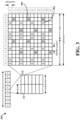
- FIG. 3 is a diagram 300 illustrating an example of a DL frame structure in LTE.
- a frame (10 ms) may be divided into 10 equally sized subframes. Each subframe may include two consecutive time slots.
- a resource grid may be used to represent two time slots, each time slot including a resource block.
- the resource grid is divided into multiple resource elements.
- a resource block contains 12 consecutive subcarriers in the frequency domain and 7 consecutive OFDM symbols in the time domain, for a total of 84 resource elements.
- For an extended cyclic prefix a resource block contains 12 consecutive subcarriers in the frequency domain and 6 consecutive OFDM symbols in the time domain, for a total of 72 resource elements.
- Some of the resource elements, indicated as R 302, 304, include DL reference signals (DL-RS).
- the DL-RS include Cell-specific RS (CRS) (also sometimes called common RS) 302 and UE-specific RS (UE-RS) 304.
- UE-RS 304 are transmitted on the resource blocks upon which the corresponding physical DL shared channel (PDSCH) is mapped.
- PDSCH physical DL shared channel
- the number of bits carried by each resource element depends on the modulation scheme. Thus, the more resource blocks that a UE receives and the higher the modulation scheme, the higher the data rate for the UE.
- FIG. 4 is a diagram 400 illustrating an example of an UL frame structure in LTE.
- the available resource blocks for the UL may be partitioned into a data section and a control section.
- the control section may be formed at the two edges of the system bandwidth and may have a configurable size.
- the resource blocks in the control section may be assigned to UEs for transmission of control information.
- the data section may include all resource blocks not included in the control section.
- the UL frame structure results in the data section including contiguous subcarriers, which may allow a single UE to be assigned all of the contiguous subcarriers in the data section.
- a UE may be assigned resource blocks 410a, 410b in the control section to transmit control information to an eNB.
- the UE may also be assigned resource blocks 420a, 420b in the data section to transmit data to the eNB.
- the UE may transmit control information in a physical UL control channel (PUCCH) on the assigned resource blocks in the control section.
- the UE may transmit data or both data and control information in a physical UL shared channel (PUSCH) on the assigned resource blocks in the data section.
- a UL transmission may span both slots of a subframe and may hop across frequency.
- a set of resource blocks may be used to perform initial system access and achieve UL synchronization in a physical random access channel (PRACH) 430.
- the PRACH 430 carries a random sequence and cannot carry any UL data/signaling.
- Each random access preamble occupies a bandwidth corresponding to six consecutive resource blocks.
- the starting frequency is specified by the network. That is, the transmission of the random access preamble is restricted to certain time and frequency resources. There is no frequency hopping for the PRACH.
- the PRACH attempt is carried in a single subframe (1 ms) or in a sequence of few contiguous subframes and a UE can make a single PRACH attempt per frame (10 ms).
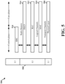
- FIG. 5 is a diagram 500 illustrating an example of a radio protocol architecture for the user and control planes in LTE.
- the radio protocol architecture for the UE and the eNB is shown with three layers: Layer 1, Layer 2, and Layer 3.
- Layer 1 (L1 layer) is the lowest layer and implements various physical layer signal processing functions.
- the L1 layer will be referred to herein as the physical layer 506.
- Layer 2 (L2 layer) 508 is above the physical layer 506 and is responsible for the link between the UE and eNB over the physical layer 506.
- the L2 layer 508 includes a media access control (MAC) sublayer 510, a radio link control (RLC) sublayer 512, and a packet data convergence protocol (PDCP) 514 sublayer, which are terminated at the eNB on the network side.
- MAC media access control
- RLC radio link control
- PDCP packet data convergence protocol
- the UE may have several upper layers above the L2 layer 508 including a network layer (e.g., IP layer) that is terminated at the PDN gateway 118 on the network side, and an application layer that is terminated at the other end of the connection (e.g., far end UE, server, etc.).
- IP layer e.g., IP layer
- the PDCP sublayer 514 provides multiplexing between different radio bearers and logical channels.
- the PDCP sublayer 514 also provides header compression for upper layer data packets to reduce radio transmission overhead, security by ciphering the data packets, and handover support for UEs between eNBs.
- the RLC sublayer 512 provides segmentation and reassembly of upper layer data packets, retransmission of lost data packets, and reordering of data packets to compensate for out-of-order reception due to hybrid automatic repeat request (HARQ).
- HARQ hybrid automatic repeat request
- the MAC sublayer 510 provides multiplexing between logical and transport channels.
- the MAC sublayer 510 is also responsible for allocating the various radio resources (e.g., resource blocks) in one cell among the UEs.
- the MAC sublayer 510 is also responsible for HARQ operations.
- the radio protocol architecture for the UE and eNB is substantially the same for the physical layer 506 and the L2 layer 508 with the exception that there is no header compression function for the control plane.
- the control plane also includes a radio resource control (RRC) sublayer 516 in Layer 3 (L3 layer).
- RRC sublayer 516 is responsible for obtaining radio resources (e.g., radio bearers) and for configuring the lower layers using RRC signaling between the eNB and the UE.
- FIG. 6 is a block diagram of an eNB 610 in communication with a UE 650 in an access network.
- upper layer packets from the core network are provided to a controller/processor 675.
- the controller/processor 675 implements the functionality of the L2 layer.
- the controller/processor 675 provides header compression, ciphering, packet segmentation and reordering, multiplexing between logical and transport channels, and radio resource allocations to the UE 650 based on various priority metrics.
- the controller/processor 675 is also responsible for HARQ operations, retransmission of lost packets, and signaling to the UE 650.
- the transmit (TX) processor 616 implements various signal processing functions for the L1 layer (i.e., physical layer).
- the signal processing functions include coding and interleaving to facilitate forward error correction (FEC) at the UE 650 and mapping to signal constellations based on various modulation schemes (e.g., binary phase-shift keying (BPSK), quadrature phase-shift keying (QPSK), M-phase-shift keying (M-PSK), M-quadrature amplitude modulation (M-QAM)).
- FEC forward error correction
- BPSK binary phase-shift keying
- QPSK quadrature phase-shift keying
- M-PSK M-phase-shift keying
- M-QAM M-quadrature amplitude modulation
- Each stream is then mapped to an OFDM subcarrier, multiplexed with a reference signal (e.g., pilot) in the time and/or frequency domain, and then combined together using an Inverse Fast Fourier Transform (IFFT) to produce a physical channel carrying a time domain OFDM symbol stream.
- the OFDM stream is spatially precoded to produce multiple spatial streams.
- Channel estimates from a channel estimator 674 may be used to determine the coding and modulation scheme, as well as for spatial processing.
- the channel estimate may be derived from a reference signal and/or channel condition feedback transmitted by the UE 650.
- Each spatial stream may then be provided to a different antenna 620 via a separate transmitter 618TX.
- Each transmitter 618TX may modulate an RF carrier with a respective spatial stream for transmission.
- each receiver 654RX receives a signal through its respective antenna 652.
- Each receiver 654RX recovers information modulated onto an RF carrier and provides the information to the receive (RX) processor 656.
- the RX processor 656 implements various signal processing functions of the L1 layer.
- the RX processor 656 may perform spatial processing on the information to recover any spatial streams destined for the UE 650. If multiple spatial streams are destined for the UE 650, they may be combined by the RX processor 656 into a single OFDM symbol stream.
- the RX processor 656 then converts the OFDM symbol stream from the time-domain to the frequency domain using a Fast Fourier Transform (FFT).
- FFT Fast Fourier Transform
- the symbols on each subcarrier, and the reference signal, are recovered and demodulated by determining the most likely signal constellation points transmitted by the eNB 610. These soft decisions may be based on channel estimates computed by the channel estimator 658. The soft decisions are then decoded and deinterleaved to recover the data and control signals that were originally transmitted by the eNB 610 on the physical channel. The data and control signals are then provided to the controller/processor 659.
- the controller/processor 659 implements the L2 layer.
- the controller/processor can be associated with a memory 660 that stores program codes and data.
- the memory 660 may be referred to as a computer-readable medium.
- the controller/processor 659 provides demultiplexing between transport and logical channels, packet reassembly, deciphering, header decompression, control signal processing to recover upper layer packets from the core network.
- the upper layer packets are then provided to a data sink 662, which represents all the protocol layers above the L2 layer.
- Various control signals may also be provided to the data sink 662 for L3 processing.
- the controller/processor 659 is also responsible for error detection using an acknowledgement (ACK) and/or negative acknowledgement (NACK) protocol to support HARQ operations.
- ACK acknowledgement
- NACK negative acknowledgement
- a data source 667 is used to provide upper layer packets to the controller/processor 659.
- the data source 667 represents all protocol layers above the L2 layer.
- the controller/processor 659 implements the L2 layer for the user plane and the control plane by providing header compression, ciphering, packet segmentation and reordering, and multiplexing between logical and transport channels based on radio resource allocations by the eNB 610.
- the controller/processor 659 is also responsible for HARQ operations, retransmission of lost packets, and signaling to the eNB 610.
- Channel estimates derived by a channel estimator 658 from a reference signal or feedback transmitted by the eNB 610 may be used by the TX processor 668 to select the appropriate coding and modulation schemes, and to facilitate spatial processing.
- the spatial streams generated by the TX processor 668 may be provided to different antenna 652 via separate transmitters 654TX. Each transmitter 654TX may modulate an RF carrier with a respective spatial stream for transmission.
- the UL transmission is processed at the eNB 610 in a manner similar to that described in connection with the receiver function at the UE 650.
- Each receiver 618RX receives a signal through its respective antenna 620.
- Each receiver 618RX recovers information modulated onto an RF carrier and provides the information to a RX processor 670.
- the RX processor 670 may implement the L1 layer.
- the controller/processor 675 implements the L2 layer.
- the controller/processor 675 can be associated with a memory 676 that stores program codes and data.
- the memory 676 may be referred to as a computer-readable medium.
- the controller/processor 675 provides demultiplexing between transport and logical channels, packet reassembly, deciphering, header decompression, control signal processing to recover upper layer packets from the UE 650.
- Upper layer packets from the controller/processor 675 may be provided to the core network.
- the controller/processor 675 is also responsible for error detection using an ACK and/or NACK protocol to support HARQ operations.
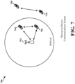
- FIG. 7 is a diagram of a device-to-device communications system 700.
- the device-to-device communications system 700 includes a plurality of wireless devices 704, 706, 708, 710.
- the device-to-device communications system 700 may overlap with a cellular communications system, such as for example, a wireless wide area network (WWAN).
- WWAN wireless wide area network
- Some of the wireless devices 704, 706, 708, 710 may communicate together in device-to-device communication using the DL/LTL WWAN spectrum, some may communicate with the base station 702, and some may do both.
- the wireless devices 708, 710 are in device-to-device communication and the wireless devices 704, 706 are in device-to-device communication.
- the wireless devices 704, 706 are also communicating with the base station 702.
- the exemplary methods and apparatuses discussed infra are applicable to any of a variety of wireless device-to-device communications systems, such as for example, a wireless device-to-device communication system based on FlashLinQ, WiMedia, Bluetooth, ZigBee, or Wi-Fi based on the IEEE 802.11 standard.
- a wireless device-to-device communication system based on FlashLinQ, WiMedia, Bluetooth, ZigBee, or Wi-Fi based on the IEEE 802.11 standard.
- the exemplary methods and apparatus are discussed within the context of LTE.
- one of ordinary skill in the art would understand that the exemplary methods and apparatuses are applicable more generally to a variety of other wireless device-to-device communication systems.
- the UL-DL subframe configuration of a radio frame may be fixed from radio frame to radio frame. That is, for each radio frame, there may be a fixed number of subframes allocated for downlink communication and a fixed number of subframes allocated for uplink communication.
- traffic patterns may vary, and there may be times in which a greater number of downlink (or uplink) resources are required than what has been allocated.
- eIMTA Enhanced Interference Mitigation and Traffic Adaption
- resource configurations for TDD may be dynamically allocated, which allows for more flexible resource configurations.
- a base station e.g., an eNB
- the base station may initially utilize a first subframe configuration in a radio frame.
- the base station may adopt a second subframe configuration to accommodate changes in network traffic. For example, if downlink transmissions increase, the base station may transmit downlink data in a resource currently allocated for downlink communication but previously allocated for uplink communication.
- FIG. 8A is an exemplary diagram 800 of uplink-downlink subframe configurations in LTE-TDD with eIMTA.
- LTE-TDD with eIMTA may use 7 UL-DL subframe configurations for WAN communication.
- Each of the 7 configurations may have a set of anchor subframes and non-anchor subframes.
- Anchor subframes also known as common subframes, may remain the same across different UL-DL subframe configurations.
- Non-anchor subframes may be changed dynamically based on traffic patterns of the network. Special non-anchor subframes may enable transition of traffic between downlink and uplink subframes.
- FIG. 8A LTE-TDD with eIMTA may use 7 UL-DL subframe configurations for WAN communication.
- Each of the 7 configurations may have a set of anchor subframes and non-anchor subframes.
- Anchor subframes also known as common subframes, may remain the same across different UL-DL subframe configurations.
- subframes 0, 1, 2, 5 may be anchor subframes that do not change from configuration to configuration.
- Subframes 3, 4, 7, 8, 9 may be non-anchor subframes that may be dynamically configured based network traffic patterns (e.g., uplink subframes may be dynamically configured to be downlink subframes when traffic is downlink heavy or vice versa).
- Subframe 6 may be a special non-anchor subframe that may be allocated for transitions between downlink and uplink subframes (e.g., when denoted by S in UL-DL configurations 0, 1, 2, 6) or may be allocated as a downlink subframes (e.g., when denoted by D in UL-DL subframe configurations 3, 4, 5).
- FIG. 8A depicts 7 different UL-DL subframe configurations that may be selected based on traffic adaption.
- a default configuration in LTE-TDD may be chosen to be uplink heavy (e.g., UL-DL subframe configurations 0, 1).
- the more downlink heavy configurations e.g., UL-DL subframe configurations 4, 5) may be selected.
- Different configurations may be chosen by converting certain non-anchor uplink subframes into downlink subframes. For example, subframes 7, 8 in UL-DL configuration 1 are converted into downlink subframes in UL-DL configuration 4.
- a downlink heavy configuration is used and more uplink resources are needed, a more uplink heavy configuration may be selected.
- D2D transmission may include D2D communications, D2D discovery, and/or D2D synchronization
- semi-statically configured D2D subframes e.g., uplink subframes with resources reserved for D2D communications
- traffic adaptation or UL-DL subframe reconfiguration
- the assigned D2D subframes may be converted from uplink into downlink subframes based on downlink traffic demand (or converted from downlink into uplink subframes based on uplink traffic demand).
- uplink subframes are converted into downlink subframes, D2D transmission on subframes previously allocated for uplink may introduce interference to the eIMTA UEs that are receiving downlink data from an eNB as illustrated in FIG. 8B .
- FIG. 8B illustrates potential interference scenarios in an eIMTA LTE-TDD network 850 with D2D and WAN co-existence.
- the eIMTA LTE-TDD network 850 includes a base station 852, a first UE 854, a second UE 856, and a third UE 858.
- the first UE 854 and the second UE 856 may have a D2D communication link and send or receive D2D transmissions 860 (e.g., D2D communications, D2D discovery messages, D2D synchronization messages) using uplink subframes.
- D2D transmissions 860 e.g., D2D communications, D2D discovery messages, D2D synchronization messages
- the base station 852 may be using UL-DL subframe configuration 0, and the first and second UEs 854, 856 may be using subframe 4, for example, for D2D transmissions. Subsequently, the third UE 858 may request a downlink transmission, which requires more downlink resources than what is offered by the UL-DL subframe configuration 0.
- the base station 852 may reconfigure the UL-DL configuration from configuration 0 to configuration 1, for example, after determining that additional downlink resources are needed. Having reconfigured the UL-DL subframe configuration, the base station 852 may send WAN transmissions 862 to the third UE 858 using resources in subframe 4, which was previously allocated for D2D transmissions.
- the WAN transmissions 862 on the downlink from the base station 852 to the third UE 858 may cause interference to the first UE 854, which is receiving D2D transmissions 860 from the second UE 856 on subframe 4.
- the D2D transmissions 860 may introduce interference to the third UE 858 (or other eIMTA UEs that are receiving downlink data from the eNB over resources in subframe 4).
- FIG. 8B illustrates three UEs, any number of UEs may be in the cell.
- FIG. 9 illustrates a method of dynamically signaling a change in LTE-TDD configurations in the presence of D2D transmissions in a wireless network 900.
- the wireless network 900 may include a base station 902 (e.g., an eNB), a first UE 904, a second UE 906, and a third UE 908 (or any other number of eNBs and/or UEs).
- the base station 902 may initially use UL-DL subframe configuration 0 for WAN (and D2D) transmissions.
- the first and second UEs 904, 906 may be allocated D2D resources on subframes 3, 4 for D2D transmissions.
- the first and second UEs 904, 906 may transmit and/or receive D2D transmissions 910 on D2D resources allocated in subframes 3, 4.
- the third UE 908 and/or other UEs may request downlink WAN transmissions 912 from the base station 902.
- the third UE 908 may request and initiate a video stream, which may require more downlink resources.
- UL-DL subframe configuration 0 has 2 subframes (e.g., subframes 0, 5) allocated for downlink communication
- the base station 902 determines that the current UL-DL subframe configuration does not support the anticipated downlink traffic.
- the base station 902 reconfigures/ changes the UL-DL configuration and select UL-DL configuration 1, for example.
- UL-DL configuration 1 subframes 4, 9 have been converted from uplink to downlink use.
- the base station 902 transmits a configuration update message 914 to all UEs being served by the base station 902.
- the configuration update message 914 may be broadcasted.
- the configuration update message 914 indicates a new UL-DL subframe configuration selected by the base station 902 and be associated with one or more radio frames.
- the configuration update message 914 may include an indicator (e.g., a configuration indicator) having two or more bits to indicate the subframe configuration (e.g., the two or more bits may be used to indicate a number between 0-6).
- the indicator may indicate a set of downlink subframes (e.g., subframes 0, 5 in configuration 0) and a set of uplink subframes (e.g., subframes 2, 3, 4, 7, 8, 9 in configuration 0).
- wireless devices within the wireless network 900 may be preconfigured with information that enables the wireless devices to associate various indicator values with different UL-DL subframe configurations.
- the first, second, and third UEs 904, 906, 908 receive the configuration update message 914 and determine which subframes are allocated for uplink versus downlink transmission.
- the base station 902 may have allocated subframes 3, 4 to the first and second UEs 904, 906 for D2D transmissions. After the change in UL-DL configuration, subframe 4 is now allocated for downlink transmission. If the first UE 904 or the second UE 906 continues to perform D2D transmissions on subframe 4 while the base station 902 and the third UE 908 are also using subframe 4 for downlink communications, then the first and second UEs 904, 906 may cause interference to the base station 902 and/or the third UE 908. In an aspect, the configuration update message 914 may not indicate whether any new resources have been allocated for D2D transmissions.
- the configuration update message 914 may not indicate that resources previously allocated for D2D transmissions should no longer be used for D2D transmissions. As such, the first and second UEs 904, 906 may continue to use subframe 4 for D2D transmissions, which could lead to unintended interference.
- the first and second UEs 904, 906 may monitor downlink transmissions for signaling (e.g., L1 signaling) from the base station 902.
- the signaling may indicate, before the occurrence of a resource, whether the resource previously allocated for D2D transmissions will be to be used for downlink transmission, and therefore, should no longer be used for D2D transmissions.
- the first and second UEs 904, 906 may perform such monitoring while in an RRC IDLE and/or an RRC CONNECTED state.
- the base station 902 (according to the invention as claimed) allocates different/new resources for D2D transmissions based on the reconfigured UL-DL configuration. For example, the base station 902 may identify the uplink subframes under the reconfigured UL-DL configuration and reserve a subset of resources (e.g., time-frequency resources) within the uplink subframes for scheduling assignment and for data transmission in D2D transmissions. In an aspect, the base station 902 (according to the invention as claimed) transmits (or broadcast) signaling that indicates newly allocated D2D resources in a D2D resource message 916.
- resources e.g., time-frequency resources
- the D2D resource message 916 may indicate any resources (e.g., time-frequency resources associated with one or more subframes) newly allocated for D2D transmissions in one or more uplink subframes according to the reconfigured UL-DL subframe configuration.
- the resources allocated for D2D transmissions may be for one or more radio frames.
- the number of radio frames for which the resources are allocated are (according to the invention as claimed) indicated in the D2D resource message 916.
- the D2D resource message 916 may also identify any subframes that were previously allocated for uplink transmission in the previous UL-DL configuration that will be converted to downlink subframes.
- the D2D resource message 916 may include a bitmap that indicates the uplink subframes associated with D2D transmissions that will be converted into downlink subframes for future radio frames.
- the base station 902 may transmit the D2D resource message 916 over a physical downlink control channel (PDCCH).
- the D2D resource message 916 may include a cyclic redundancy check (CRC) appended to the D2D resource message 916.
- the CRC may be scrambled with an identifier such as a radio network temporary identifier (RNTI).
- the RNTI may be a Broadcast D2D-RNTI, which may be a common RNTI known to all UEs interested in D2D transmissions.
- the identifier may be broadcast by the base station 902 in a system information block (SIB) (e.g., the base station 902 may send the Broadcast D2D-RNTI in a SIB1).
- SIB system information block
- UEs not interested in D2D transmissions may ignore the D2D resource message 916, and UEs interested in D2D transmissions (e.g., the first UE 904 and the second UE 906) may decode the D2D resource message 916 based on the identifier.
- the first and second UEs 904, 906 may decode the D2D resource message 916 using the identifier.
- the first and second UEs 904, 906 may determine that subframe 4, previously an uplink subframe containing resources for D2D transmissions, is now a downlink subframe.
- the first and second UEs 904, 906 may refrain from performing D2D transmissions on subframe 4 (and on any other subframes converted from uplink to downlink subframes). That is, in this example, the first and second UEs 904, 906 may not transmit or receive D2D communications on subframe 4.
- the first and second UEs 904, 906 may determine, based on the received D2D resource message 916, the resources allocated for D2D transmissions within one or more uplink subframes in the reconfigured UL-DL subframe configuration. In this configuration, an offset between when the D2D resource message 916 (or other L1 signaling) is sent and when the D2D resources occur may be fixed (e.g., predetermined) or configurable based on network signaling.
- the base station 902 may have more detailed information regarding D2D transmissions to send to the first and second UEs 904, 906.
- the D2D resource message 916 may not be able to transmit all of the detailed information in the PDCCH. Instead, the base station 902 may transmit the D2D resource message 916 to indicate a resource (e.g., a set of time-frequency resources) on which a D2D information message 918 will be transmitted. Similar to the D2D resource message 916 discussed in the previous configuration, the D2D information message 918 (according to the invention as claimed) indicates resources for D2D transmissions in a reconfigured UL-DL subframe configuration.
- the D2D information message 918 (according to the invention as claimed) is used to indicate resources allocated for D2D transmissions rather than the D2D resource message 916.
- the D2D resource message 916 may enable the first and second UEs 904, 906 to locate the D2D information message 918.
- the D2D information message 918 may indicate the resources for D2D transmissions in a greater number of radio frames than could be indicated in the D2D resource message 916 in the previously discussed configuration.
- the D2D information message 918 (according to the invention as claimed) indicates that the D2D resources have been allocated for an indicated number of radio frames. In other words, the D2D information message 918 may carry more information/data than D2D resource message 916.
- the D2D information message 918 may indicate which uplink subframes have been converted to downlink subframes.
- the D2D information message 918 may also include parameters associated with one or more D2D communication links. Such parameters may include a suggested transmission power for D2D transmissions, a suggested modulation and coding scheme (MCS) for D2D transmissions, and/or a bitmap that indicates the uplink subframes associated with D2D transmissions that will be converted into downlink subframes for future radio frames.
- MCS modulation and coding scheme
- a bitmap carried by the D2D information message 918 may be larger than a bitmap carried by the D2D resource message 916.
- the base station 902 may transmit the D2D resource message 916 over a PDCCH and transmit the D2D information message 918 over a PDSCH.
- an offset between when the D2D resource message 918 (or other L1 signaling) is sent and when the D2D resources occur may be fixed or configurable.
- the first and second UEs 904, 906 determine a subset of the allocated D2D resources to be used for performing D2D transmissions. In an aspect, if the first UE 904 has a large amount of data to send, then the first UE 904 may select a larger subset of the allocated D2D resources to use for the D2D transmissions 910. In another aspect, if the first UE 904 has less data to send, then the first UE 904 may select a smaller subset of the allocated D2D resources to use for the D2D transmissions 910.
- resource selection may also be based on priority of the data to be transmitted. If the first UE 904 has high priority data for transmission, then the first UE 904 may select a larger subset of the allocated D2D resources, but if the first UE 904 has low priority data for transmission, then the first UE 904 may select a smaller subset of the allocated D2D resources and leave the remaining resources for other UEs. Similarly, if other UEs in the wireless network 900 are engaging in D2D transmissions (e.g., D2D communications), the first UE 904 may select the subset of D2D resources based on an energy detection level on the D2D resources.
- D2D transmissions e.g., D2D communications
- the first UE 904 may select a subset of resources with a comparatively lower energy detection level to minimize interference with other D2D transmissions.
- the D2D resource message 916 or the D2D information message 918 may indicate which resources are allocated to which UEs for D2D transmissions based on a UE identifier (e.g., a MAC address).
- the first UE 904 may determine the subset of resources to use for D2D transmissions based on which resources are associated with the identifier of the first UE 904.
- the subset of allocated D2D resources selected by the first UE 904 may include all the resources allocated for D2D transmissions.
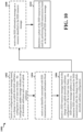
- FIG. 10 is a flowchart 1000 of a method of wireless communication.
- the method may be performed by a UE (e.g., the first UE 904, the second UE 906, the apparatus 1202/1202', infra ).
- the UE receives a configuration update message based on a change in an uplink-downlink subframe configuration of at least one frame.
- the configuration update message indicates a set of downlink subframes and a set of uplink subframes.
- the first UE 904 may receive the configuration update message 914 based on a change in the UL-DL subframe configuration (e.g., from configuration 0 to configuration 1) of at least one frame.
- the configuration update message 914 may indicate a set of downlink subframes (0, 4, 5, 9) and a set of uplink subframes (2, 3, 7, 8).
- the UE may receive an identifier associated with D2D transmissions in a system information block.
- the first UE 904 may receive a Broadcast D2D-RNTI associated with D2D transmissions from the base station 902 in a SIB1.
- the UE receives a D2D resource message based on the change in the uplink-downlink subframe configuration of the at least one frame.
- the D2D resource message may enable the UE to determine D2D resources allocated for D2D transmissions after the change in the uplink-downlink subframe configuration.
- the D2D resource message may indicate the D2D resources, in a set of uplink subframes, allocated for D2D transmissions.
- the D2D resource message may be transmitted in a PDCCH.
- the D2D resource message may identify resources on which a D2D information message will be transmitted, and the D2D information message may indicate the D2D resources, in a set of uplink subframes, allocated for D2D transmissions.
- the first UE 904 may receive the D2D resource message 916 based on the change in the UL-DL subframe configuration of at least one radio frame.
- the D2D resource message 916 may enable the first UE 904 to determine D2D resources allocated for D2D transmissions after the change in the UL-DL subframe configuration from configuration 0 to configuration 1.
- the D2D resource message 916 may be transmitted on the PDCCH and may indicate the D2D resources, in a set of uplink subframes (e.g., subframes 3, 7 of configuration 1), allocated for D2D transmissions.
- the D2D resource message 916 may identify a resource on which the D2D information message 918 will be transmitted.
- the D2D information message 918 may indicate the D2D resources, in a set of uplink subframes (e.g., subframes 3, 7 of configuration 1), allocated for D2D transmissions.
- the UE may receive the D2D information message on a resource identified in the D2D resource message.
- the D2D resource message may be received in a PDCCH and the D2D information message may be received in a PDSCH.
- the D2D information message may include a bitmap that indicates one or more subframes of the at least one frame that will be converted to a downlink subframe or converted to an uplink subframe based on the change in the uplink-downlink subframe configuration.
- the first UE 904 may receive the D2D information message 918 on the resource identified in the D2D resource message 916.
- the D2D resource message 916 may be received in the PDCCH and the D2D information message 918 may be received in the PDSCH.
- the D2D information message 918 may include a bitmap that indicates that subframes 4, 9 of the next 12 radio frames will be converted to a downlink subframe based on the change in the UL-DL subframe configuration.
- the UE determines a subset of the D2D resources to be used for performing D2D transmissions based on the received D2D resource message.
- the UE may determine the subset of the D2D resources to be used for performing D2D transmissions by identifying a downlink subframe previously configured as an uplink subframe and previously associated with resources allocated for D2D transmissions and refrain from performing D2D transmissions on the identified downlink subframe.
- the UE may determine the subset of D2D resources to be used for performing D2D transmissions by decoding the D2D resources message based on an identifier associated with D2D transmissions. For example, referring to FIG.
- the first UE 904 may determine a subset of the D2D resources to be used for performing D2D transmissions with the second UE 906 based on the received D2D resource message 916.
- the first UE 904 may use the Broadcast D2D-RNTI to decode the D2D resource message 916.
- the D2D resource message 916 may indicate the D2D resources for D2D transmissions.
- the D2D resource message 916 may provide the resource(s) for receiving the D2D information message 918, and the first UE 904 may receive the D2D information message 918 on the resource(s) indicated by the D2D resource message 916.
- the first UE 904 may decode the D2D information message 918 and determine the resources allocated for D2D transmissions. Having determined the D2D resources indicated in either the D2D resource message 916 or the D2D information message 918, the first UE 904 may use a subset of the D2D resources allocated for D2D transmissions. In an aspect, the subset may include all of the D2D resources allocated for D2D transmissions. In another aspect, the subset may include a portion of the D2D resources allocated for D2D transmissions.
- the portion may be selected based on an energy detection level of the available D2D resources, a priority of transmission of the first UE 904, and/or specific resource assignments to the first UE 904 indicated in the D2D resource message 916 or the D2D information message 918.
- FIG. 11 is a flowchart 1100 of a method of wireless communication.
- the method may be performed by a base station (e.g., the base station 902, the apparatus 1402/1402', infra ).
- the base station determines to reconfigure an uplink-downlink subframe configuration of at least one frame based on network traffic.
- the base station 902 may determine to reconfigure an UL-DL subframe configuration of at least one radio frame based on the traffic in the wireless network 900.
- the base station 902 may receive a request from the third UE 908 requesting additional downlink transmissions (e.g., to support a video streaming service).
- the base station 902 may be using UL-DL subframe configuration 0 and may determine that the current configuration does not have enough downlink subframes to support the throughput required by the third UE 908. Accordingly, the base station 902 may determine that additional downlink subframes are required. In an aspect, the base station 902 may determine the amount of downlink subframes needed to support the traffic throughput. For example, the base station 902 may determine that 2 more downlink subframes are needed.
- the base station reconfigures the uplink-downlink subframe configuration based on the determination. For example, referring to FIG. 9 , the base station 902 may reconfigure the UL-DL subframe configuration based on the determination that reconfiguration is needed. In an aspect, the base station 902 may identify one or more UL-DL subframe configurations that have more downlink subframes than a current UL-DL subframe configuration and switch to anyone of the identified one or more UL-DL subframe configurations.
- the base station 902 may determine the number of additional downlink subframes required to support the additional network downlink (e.g., 2 more downlink subframes), identify one or more UL-DL subframe configurations that satisfy the requirement, and switch to the one or more UL-DL subframe configuration (e.g., the base station 902 may reconfigure the UL-DL subframe configuration from configuration 0 to configuration 1).
- the base station 902 may determine the number of additional downlink subframes required to support the additional network downlink (e.g., 2 more downlink subframes), identify one or more UL-DL subframe configurations that satisfy the requirement, and switch to the one or more UL-DL subframe configuration (e.g., the base station 902 may reconfigure the UL-DL subframe configuration from configuration 0 to configuration 1).
- the base station transmits a configuration update message based on the reconfigured uplink-downlink subframe configuration of the at least one frame.
- the configuration update message may indicate a set of downlink subframes and a set of uplink subframes.
- the base station 902 may transmit the configuration update message 914 based on the reconfigured UL-DL subframe configuration of the at least one radio frame.
- the configuration update message 914 may indicate a set of downlink subframes (e.g., subframes 0, 4, 5, 9) and a set of uplink subframes (e.g., 2, 3, 7, 8).
- the configuration update message 914 may indicate the set of downlink subframes and the set of uplink subframes by a bit indicator (e.g., 2-bit indicator) that corresponds to a configuration number (configuration 0-6).
- the base station may allocate D2D resources for D2D transmissions based on the reconfigured uplink-downlink subframe configuration.
- the reconfigured uplink-downlink subframe configuration may have less uplink subframes than a previous uplink-downlink subframe configuration, and a subset of the D2D resources are allocated on a subset of uplink subframes not previously allocated for D2D transmissions in the previous uplink-downlink subframe configuration.
- the base station 902 may allocate D2D resources for D2D transmissions based on the reconfiguration UL-DL subframe configuration.
- the base station 902 may determine that configuration 1 is the new UL-DL subframe configuration.
- Configuration 1 may have less uplink subframes (e.g., 4 uplink subframes) than configuration 0 (e.g., 6 uplink subframes).
- the base station 902 may determine that, in configuration 1, subframes 2, 3, 7, 8 are uplink subframes.
- the base station 902 may allocate D2D resources within the subframes 3, 7 of configuration 1 (versus subframes 3, 4 of configuration 0).
- the base station 902 may allocate specific D2D resources to specific UEs (e.g., the first UE 904 and the second UE 906). In this aspect, the allocation may be based on a distance between the base station 902 and the UE.
- the base station 902 may convert/reallocate some of the data resources into scheduling assignment resources.
- the base station may transmit an identifier associated with D2D transmissions in a system information block to enable a UE to decode a D2D resource message.
- the base station 902 may transmit a Broadcast D2D-RNTI associated with D2D transmissions in a SIB1 to enable the first UE 904 to decode the D2D resource message 916.
- the base station transmits the D2D resource message based on the reconfigured uplink-downlink subframe configuration.
- the D2D resource message may enable the UE to determine the D2D resources allocated for D2D transmissions based on the reconfigured uplink-downlink subframe configuration.
- the D2D resource message may indicate the D2D resources allocated in a set of uplink subframes.
- the D2D resource message may identify a resource on which a D2D information message will be transmitted.
- the D2D information message may indicate the D2D resources allocated in a set of uplink subframes based on the reconfigured uplink-downlink subframe configuration. For example, referring to FIG.
- the base station 902 may transmit the D2D resource message 916 based on the reconfigured UL-DL subframe configuration.
- the D2D resource message 916 enables the first UE 904 to determine the D2D resources allocated for D2D transmissions based on the reconfigured UL-DL subframe configuration.
- the D2D resource message 916 may indicate the D2D resources allocated in uplink subframes 3 and 7.
- the D2D resource message 916 identifies a resource on which the D2D information message 918 will be transmitted (e.g., one or more symbols and associated subcarriers), and the D2D information message will indicate the D2D resources allocated in the uplink subframes 3, 7 based on configuration 1.
- the base station may transmit the D2D information message on the resource identified in the D2D resource message.
- the base station 902 may transmit the D2D information message 918 on the resource identified in the D2D resource message 916.
- the D2D resource message 916 may be transmitted on the PDCCH, and the D2D information message 918 may be transmitted on the PDSCH.
- FIG. 12 is a conceptual data flow diagram 1200 illustrating the data flow between different modules/means/components in an exemplary apparatus 1202.
- the apparatus may be a UE.
- the apparatus includes a reception module 1204, a D2D transmission module 1206, and a transmission module 1208.
- the reception module 1204 may be configured to receive a D2D resource message from a base station 1250 based on a change in an uplink-downlink subframe configuration of at least one frame.
- the D2D resource message may enable the apparatus to determine D2D resources allocated for D2D transmissions after the change in the uplink-downlink subframe configuration.
- the D2D transmission module 1206 may be configured to determine a subset of the D2D resources to be used for performing D2D transmissions with a UE 1260 based on the received D2D resource message.
- the reception module 1204 may be configured to receive a configuration update message from the base station 1250 based on the change in the uplink-downlink subframe configuration of the at least one frame.
- the configuration update message may indicate a set of downlink subframes and a set of uplink subframes.
- the D2D transmission module 1206 may be configured to determine the subset of D2D resources to be used for performing D2D transmissions by identifying a downlink subframe previously configured as an uplink subframe and previously associated with resources allocated for D2D transmission and by refraining from performing D2D transmission on the identified downlink subframe.
- the D2D transmission module 1206 may be configured to determine the subset of D2D resources to be used for performing D2D transmissions by decoding the D2D resource message based on an identifier associated with D2D transmissions.
- the reception module 1204 may be configured to receive the identifier associated with D2D transmissions in a system information block.
- the D2D resource message may indicate the D2D resources, in a set of uplink subframes, allocated for D2D transmissions.
- the D2D resource message may be transmitted in a PDCCH.
- the D2D resource message may identify resources on which a D2D information message will be transmitted, and the D2D information message may indicate the D2D resources, in a set of uplink subframes, allocated for D2D transmissions.
- the reception module 1204 may be configured to receive the D2D information message on the resource identified in the D2D resource message.
- the D2D resource message may be received in a PDCCH and the D2D information message may be received in a PDSCH.
- the D2D information message may include a bitmap that indicates one or more subframes of the at least one frame that will be converted to a downlink subframe or converted to an uplink subframe based on the change in the uplink-downlink subframe configuration.
- the apparatus may include additional modules that perform each of the blocks of the algorithm in the aforementioned flowchart of FIG. 10 .
- each block in the aforementioned flowchart of FIG. 10 may be performed by a module and the apparatus may include one or more of those modules.
- the modules may be one or more hardware components specifically configured to carry out the stated processes/algorithm, implemented by a processor configured to perform the stated processes/algorithm, stored within a computer-readable medium for implementation by a processor, or some combination thereof.
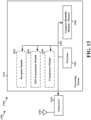
- FIG. 13 is a diagram 1300 illustrating an example of a hardware implementation for an apparatus 1202' employing a processing system 1314.
- the processing system 1314 may be implemented with a bus architecture, represented generally by the bus 1324.
- the bus 1324 may include any number of interconnecting buses and bridges depending on the specific application of the processing system 1314 and the overall design constraints.
- the bus 1324 links together various circuits including one or more processors and/or hardware modules, represented by the processor 1304, the modules 1204, 1206, 1208, and the computer-readable medium / memory 1306.
- the bus 1324 may also link various other circuits such as timing sources, peripherals, voltage regulators, and power management circuits, which are well known in the art, and therefore, will not be described any further.
- the processing system 1314 may be coupled to a transceiver 1310.
- the transceiver 1310 is coupled to one or more antennas 1320.
- the transceiver 1310 provides a means for communicating with various other apparatus over a transmission medium.
- the transceiver 1310 receives a signal from the one or more antennas 1320, extracts information from the received signal, and provides the extracted information to the processing system 1314, specifically the reception module 1204.
- the transceiver 1310 receives information from the processing system 1314, specifically the transmission module 1208, and based on the received information, generates a signal to be applied to the one or more antennas 1320.
- the processing system 1314 includes a processor 1304 coupled to a computer-readable medium / memory 1306.
- the processor 1304 is responsible for general processing, including the execution of software stored on the computer-readable medium / memory 1306.
- the software when executed by the processor 1304, causes the processing system 1314 to perform the various functions described supra for any particular apparatus.
- the computer-readable medium / memory 1306 may also be used for storing data that is manipulated by the processor 1304 when executing software.
- the processing system further includes at least one of the modules 1204, 1206, 1208.
- the modules may be software modules running in the processor 1304, resident/stored in the computer readable medium / memory 1306, one or more hardware modules coupled to the processor 1304, or some combination thereof.
- the processing system 1314 may be a component of the UE 650 and may include the memory 660 and/or at least one of the TX processor 668, the RX processor 656, and the controller/processor 659.
- the apparatus 1202/1202' for wireless communication includes means for receiving a D2D resource message based on a change in an uplink-downlink subframe configuration of at least one frame.
- the D2D resource message may enable the apparatus to determine D2D resources allocated for D2D transmissions after the change in the uplink-downlink subframe configuration.
- the apparatus includes means for determining a subset of the D2D resources to be used for performing D2D transmissions based on the received D2D resource message.
- the apparatus may include means for receiving a configuration update message based on the change in the uplink-downlink subframe configuration of the at least one frame.
- the configuration update message may indicate a set of downlink subframes and a set of uplink subframes.
- the means for determining the subset of D2D resources to be used for performing D2D transmissions may be configured to identify a downlink subframe previously configured as an uplink subframe and previously associated with resources allocated for D2D transmission and to refrain from performing D2D transmission on the identified downlink subframe.
- the means for determining the subset of D2D resources to be used for performing D2D transmissions may be configured to decode the D2D resource message based on an identifier associated with D2D transmissions.
- the apparatus may include means for receiving the identifier associated with D2D transmissions in a system information block.
- the D2D resource message may indicate the D2D resources, in a set of uplink subframes, allocated for D2D transmissions.
- the D2D resource message may be transmitted in a PDCCH.
- the D2D resource message may identify resources on which a D2D information message will be transmitted.
- the D2D information message may indicate the D2D resources, in a set of uplink subframes, allocated for D2D transmissions.
- the apparatus may include means for receiving the D2D information message on the resource identified in the D2D resource message.
- the D2D resource message may be received in a PDCCH and the D2D information message may be received in a PDSCH.
- the D2D information message may include a bitmap that indicates one or more subframes of the at least one frame that will be converted to a downlink subframe or converted to an uplink subframe based on the change in the uplink-downlink subframe configuration.
- the aforementioned means may be one or more of the aforementioned modules of the apparatus 1202 and/or the processing system 1314 of the apparatus 1202' configured to perform the functions recited by the aforementioned means.
- the processing system 1314 may include the TX Processor 668, the RX Processor 656, and the controller/processor 659.
- the aforementioned means may be the TX Processor 668, the RX Processor 656, and the controller/processor 659 configured to perform the functions recited by the aforementioned means.
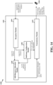
- FIG. 14 is a conceptual data flow diagram 1400 illustrating the data flow between different modules/means/components in an exemplary apparatus 1402.
- the apparatus may be a base station (e.g., an eNB).
- the apparatus includes a reception module 1404, a subframe configuration module 1406, a D2D resource allocation module 1408, and a transmission module 1410.
- the subframe configuration module 1406 may be configured to determine to reconfigure an uplink-downlink subframe configuration of at least one frame based on network traffic.
- the subframe configuration module 1406 may be configured to reconfigure the uplink-downlink subframe configuration based on the determination.
- the transmission module 1410 may be configured to transmit a D2D resource message based on the reconfigured uplink-downlink subframe configuration.
- the D2D resource message may enable a UE 1450 to determine D2D resources allocated for D2D transmissions based on the reconfigured uplink-downlink subframe configuration.
- the D2D resource allocation module 1408 may be configured to allocate the D2D resources for D2D transmissions based on the reconfigured uplink-downlink subframe configuration.
- the reconfigured uplink-downlink subframe configuration may have less uplink subframes than a previous uplink-downlink subframe configuration, and a subset of the D2D resources may be allocated on a subset of uplink subframes not previously allocated for D2D transmissions in the previous uplink-downlink subframe configuration.
- the transmission module 1410 may be configured to transmit a configuration update message based on the reconfigured uplink-downlink subframe configuration of the at least one frame.
- the configuration update message may indicate a set of downlink subframes and a set of uplink subframes.
- the transmission module 1410 may be configured to transmit an identifier associated with D2D transmissions in a system information block to enable the UE 1450 to decode the D2D resource message.
- the D2D resource message may indicate the D2D resources allocated in a set of uplink subframes.
- the D2D resource message may identify resources on which a D2D information message will be transmitted.
- the D2D information message may indicate the D2D resources allocated in a set of uplink subframes based on the reconfigured uplink-downlink subframe configuration.
- the transmission module 1410 may be configured to transmit the D2D information message on the resource identified in the D2D resource message.
- the D2D resource message may be transmitted in a PDCCH and the D2D information message may be transmitted in a PDSCH.
- the apparatus may include additional modules that perform each of the blocks of the algorithm in the aforementioned flowchart of FIG. 11 .
- each block in the aforementioned flowchart of FIG. 11 may be performed by a module and the apparatus may include one or more of those modules.
- the modules may be one or more hardware components specifically configured to carry out the stated processes/algorithm, implemented by a processor configured to perform the stated processes/algorithm, stored within a computer-readable medium for implementation by a processor, or some combination thereof.
- FIG. 15 is a diagram 1500 illustrating an example of a hardware implementation for an apparatus 1402' employing a processing system 1514.
- the processing system 1514 may be implemented with a bus architecture, represented generally by the bus 1524.
- the bus 1524 may include any number of interconnecting buses and bridges depending on the specific application of the processing system 1514 and the overall design constraints.
- the bus 1524 links together various circuits including one or more processors and/or hardware modules, represented by the processor 1504, the modules 1404, 1406, 1408, 1410, and the computer-readable medium / memory 1506.
- the bus 1524 may also link various other circuits such as timing sources, peripherals, voltage regulators, and power management circuits, which are well known in the art, and therefore, will not be described any further.
- the processing system 1514 may be coupled to a transceiver 1510.
- the transceiver 1510 is coupled to one or more antennas 1520.
- the transceiver 1510 provides a means for communicating with various other apparatus over a transmission medium.
- the transceiver 1510 receives a signal from the one or more antennas 1520, extracts information from the received signal, and provides the extracted information to the processing system 1514, specifically the reception module 1404.
- the transceiver 1510 receives information from the processing system 1514, specifically the transmission module 1410, and based on the received information, generates a signal to be applied to the one or more antennas 1520.
- the processing system 1514 includes a processor 1504 coupled to a computer-readable medium / memory 1506.
- the processor 1504 is responsible for general processing, including the execution of software stored on the computer-readable medium / memory 1506.
- the software when executed by the processor 1504, causes the processing system 1514 to perform the various functions described supra for any particular apparatus.
- the computer-readable medium / memory 1506 may also be used for storing data that is manipulated by the processor 1504 when executing software.
- the processing system further includes at least one of the modules 1404, 1406, 1408, 1410.
- the modules may be software modules running in the processor 1504, resident/stored in the computer readable medium / memory 1506, one or more hardware modules coupled to the processor 1504, or some combination thereof.
- the processing system 1514 may be a component of the eNB 610 and may include the memory 676 and/or at least one of the TX processor 616, the RX processor 670, and the controller/processor 675.
- the apparatus 1402/1402' for wireless communication includes means for determining to reconfigure an uplink-downlink subframe configuration of at least one frame based on network traffic.
- the apparatus includes means for reconfiguring the uplink-downlink subframe configuration based on the determination.
- the apparatus includes means for transmitting a D2D resource message based on the reconfigured uplink-downlink subframe configuration.
- the D2D resource message may enable a UE to determine D2D resources allocated for D2D transmissions based on the reconfigured uplink-downlink subframe configuration.
- the apparatus may include means for allocating the D2D resources for D2D transmissions based on the reconfigured uplink-downlink subframe configuration.
- the reconfigured uplink-downlink subframe configuration may have less uplink subframes than a previous uplink-downlink subframe configuration, and a subset of the D2D resources may be allocated on a subset of uplink subframes not previously allocated for D2D transmissions in the previous uplink-downlink subframe configuration.
- the apparatus may include means for transmitting a configuration update message based on the reconfigured uplink-downlink subframe configuration of the at least one frame.
- the configuration update message may indicate a set of downlink subframes and a set of uplink subframes.
- the apparatus may include means for transmitting an identifier associated with D2D transmissions in a system information block to enable the UE to decode the D2D resource message.
- the D2D resource message may indicate the D2D resources allocated in a set of uplink subframes.
- the D2D resource message may identify resources on which a D2D information message will be transmitted.
- the D2D information message may indicate the D2D resources allocated in a set of uplink subframes based on the reconfigured uplink-downlink subframe configuration.
- the apparatus may include means for transmitting the D2D information message on the resource identified in the D2D resource message.
- the D2D resource message may be transmitted in a PDCCH and the D2D information message may be transmitted in a PDSCH.
- the aforementioned means may be one or more of the aforementioned modules of the apparatus 1402 and/or the processing system 1514 of the apparatus 1402' configured to perform the functions recited by the aforementioned means.
- the processing system 1514 may include the TX Processor 616, the RX Processor 670, and the controller/processor 675.
- the aforementioned means may be the TX Processor 616, the RX Processor 670, and the controller/processor 675 configured to perform the functions recited by the aforementioned means.
- Combinations such as "at least one of A, B, or C,” “at least one of A, B, and C,” and “A, B, C, or any combination thereof' include any combination of A, B, and/or C, and may include multiples of A, multiples of B, or multiples of C.
- combinations such as “at least one of A, B, or C,” “at least one of A, B, and C,” and “A, B, C, or any combination thereof' may be A only, B only, C only, A and B, A and C, B and C, or A and B and C, where any such combinations may contain one or more member or members of A, B, or C.
- No claim element is to be construed as a means plus function unless the element is expressly recited using the phrase "means for.”
Description
- The present disclosure relates generally to communication systems, and more particularly, to dynamic signaling of Long Term Evolution Time-Division Duplex (LTE-TDD) configurations in the presence of device-to-device (D2D) transmissions.
- Wireless communication systems, as are for example described in
WO 2014/180342 A1 , 3GPP R1-132654,WO 2012/019348 A1 ,US 2014/098719 A1 ,WO 2014/004314 A2 ,US 2014/269338 A1 ,US 2014/269338 A1 , and 3GPP TS 36.213, are widely deployed to provide various telecommunication services such as telephony, video, data, messaging, and broadcasts. Typical wireless communication systems may employ multiple-access technologies capable of supporting communication with multiple users by sharing available system resources (e.g., bandwidth, transmit power). Examples of such multiple-access technologies include code division multiple access (CDMA) systems, time division multiple access (TDMA) systems, frequency division multiple access (FDMA) systems, orthogonal frequency division multiple access (OFDMA) systems, single-carrier frequency division multiple access (SC-FDMA) systems, and time division synchronous code division multiple access (TD-SCDMA) systems. - These multiple access technologies have been adopted in various telecommunication standards to provide a common protocol that enables different wireless devices to communicate on a municipal, national, regional, and even global level. An example telecommunication standard is Long Term Evolution (LTE). LTE is a set of enhancements to the Universal Mobile Telecommunications System (UMTS) mobile standard promulgated by Third Generation Partnership Project (3GPP). LTE is designed to better support mobile broadband Internet access by improving spectral efficiency, lowering costs, improving services, making use of new spectrum, and better integrating with other open standards using OFDMA on the downlink (DL), SC-FDMA on the uplink (UL), and multiple-input multipleoutput (MIMO) antenna technology. However, as the demand for mobile broadband access continues to increase, there exists a need for further improvements in LTE technology. Preferably, these improvements should be applicable to other multiaccess technologies and the telecommunication standards that employ these technologies.
- The invention is defined by the subject-matter of the independent claims. Preferred examples are specified by the dependent claims.
- In the following, the subject-matter of
fig. 9 and its description is according to the invention as claimed. The rest of the description and figures does not or does not fully and thus only partly correspond to the invention as claimed but is useful for understanding the invention. -
-
FIG. 1 is a diagram illustrating an example of a network architecture. -
FIG. 2 is a diagram illustrating an example of an access network. -
FIG. 3 is a diagram illustrating an example of a DL frame structure in LTE. -
FIG. 4 is a diagram illustrating an example of an UL frame structure in LTE. -
FIG. 5 is a diagram illustrating an example of a radio protocol architecture for the user and control planes. -
FIG. 6 is a diagram illustrating an example of an evolved Node B and user equipment in an access network. -
FIG. 7 is a diagram of a device-to-device communications system. -
FIG. 8A is an exemplary diagram of uplink-downlink subframe configurations in LTE-TDD with eIMTA. -
FIG. 8B illustrates potential interference scenarios in an eIMTA LTE-TDD network with D2D and WAN co-existence. -
FIG. 9 illustrates a method of dynamically signaling a change in LTE-TDD configurations in the presence of D2D transmissions in a wireless network. -
FIG. 10 is a flowchart of a method of wireless communication. -
FIG. 11 is a flowchart of a method of wireless communication. -
FIG. 12 is a conceptual data flow diagram illustrating the data flow between different modules/means/components in an exemplary apparatus. -
FIG. 13 is a diagram illustrating an example of a hardware implementation for an apparatus employing a processing system. -
FIG. 14 is a conceptual data flow diagram illustrating the data flow between different modules/means/components in an exemplary apparatus. -
FIG. 15 is a diagram illustrating an example of a hardware implementation for an apparatus employing a processing system. - The detailed description set forth below in connection with the appended drawings is intended as a description of various configurations and is not intended to represent the only configurations in which the concepts described herein may be practiced. The detailed description includes specific details for the purpose of providing a thorough understanding of various concepts. However, it will be apparent to those skilled in the art that these concepts may be practiced without these specific details. In some instances, well known structures and components are shown in block diagram form in order to avoid obscuring such concepts.
- Several aspects of telecommunication systems will now be presented with reference to various apparatus and methods. These apparatus and methods will be described in the following detailed description and illustrated in the accompanying drawings by various blocks, modules, components, circuits, steps, processes, algorithms, etc. (collectively referred to as "elements"). These elements may be implemented using electronic hardware, computer software, or any combination thereof. Whether such elements are implemented as hardware or software depends upon the particular application and design constraints imposed on the overall system.
- By way of example, an element, or any portion of an element, or any combination of elements may be implemented with a "processing system" that includes one or more processors. Examples of processors include microprocessors, microcontrollers, digital signal processors (DSPs), field programmable gate arrays (FPGAs), programmable logic devices (PLDs), state machines, gated logic, discrete hardware circuits, and other suitable hardware configured to perform the various functionality described throughout this disclosure. One or more processors in the processing system may execute software. Software shall be construed broadly to mean instructions, instruction sets, code, code segments, program code, programs, subprograms, software modules, applications, software applications, software packages, routines, subroutines, objects, executables, threads of execution, procedures, functions, etc., whether referred to as software, firmware, middleware, microcode, hardware description language, or otherwise.
- Accordingly, in one or more exemplary embodiments, the functions described may be implemented in hardware, software, firmware, or any combination thereof. If implemented in software, the functions may be stored on or encoded as one or more instructions or code on a computer-readable medium. Computer-readable media includes computer storage media. Storage media may be any available media that can be accessed by a computer. By way of example, and not limitation, such computer-readable media can comprise a random-access memory (RAM), a read-only memory (ROM), an electrically erasable programmable ROM (EEPROM), compact disk ROM (CD-ROM) or other optical disk storage, magnetic disk storage or other magnetic storage devices, combinations of the aforementioned types of computer-readable media, or any other medium that can be used to store computer executable code in the form of instructions or data structures that can be accessed by a computer.
-
FIG. 1 is a diagram illustrating anLTE network architecture 100. TheLTE network architecture 100 may be referred to as an Evolved Packet System (EPS) 100. The EPS 100 may include one or more user equipment (UE) 102, an Evolved UMTS Terrestrial Radio Access Network (E-UTRAN) 104, an Evolved Packet Core (EPC) 110, and an Operator's Internet Protocol (IP)Services 122. The EPS can interconnect with other access networks, but for simplicity those entities/interfaces are not shown. As shown, the EPS provides packet-switched services, however, as those skilled in the art will readily appreciate, the various concepts presented throughout this disclosure may be extended to networks providing circuit-switched services. - The E-UTRAN includes the evolved Node B (eNB) 106 and other eNBs 108, and may include a Multicast Coordination Entity (MCE) 128. The eNB 106 provides user and control planes protocol terminations toward the UE 102. The eNB 106 may be connected to the other eNBs 108 via a backhaul (e.g., an X2 interface). The
MCE 128 allocates time/frequency radio resources for evolved Multimedia Broadcast Multicast Service (MBMS) (eMBMS), and determines the radio configuration (e.g., a modulation and coding scheme (MCS)) for the eMBMS. The MCE 128 may be a separate entity or part of the eNB 106. TheeNB 106 may also be referred to as a base station, a Node B, an access point, a base transceiver station, a radio base station, a radio transceiver, a transceiver function, a basic service set (BSS), an extended service set (ESS), or some other suitable terminology. TheeNB 106 provides an access point to theEPC 110 for aUE 102. Examples ofUEs 102 include a cellular phone, a smart phone, a session initiation protocol (SIP) phone, a laptop, a personal digital assistant (PDA), a satellite radio, a global positioning system, a multimedia device, a video device, a digital audio player (e.g., MP3 player), a camera, a game console, a tablet, or any other similar functioning device. TheUE 102 may also be referred to by those skilled in the art as a mobile station, a subscriber station, a mobile unit, a subscriber unit, a wireless unit, a remote unit, a mobile device, a wireless device, a wireless communications device, a remote device, a mobile subscriber station, an access terminal, a mobile terminal, a wireless terminal, a remote terminal, a handset, a user agent, a mobile client, a client, or some other suitable terminology. - The
eNB 106 is connected to theEPC 110. TheEPC 110 may include a Mobility Management Entity (MME) 112, a Home Subscriber Server (HSS) 120,other MMEs 114, aServing Gateway 116, a Multimedia Broadcast Multicast Service (MBMS)Gateway 124, a Broadcast Multicast Service Center (BM-SC) 126, and a Packet Data Network (PDN)Gateway 118. TheMME 112 is the control node that processes the signaling between theUE 102 and theEPC 110. Generally, theMME 112 provides bearer and connection management. All user IP packets are transferred through theServing Gateway 116, which itself is connected to thePDN Gateway 118. ThePDN Gateway 118 provides UE IP address allocation as well as other functions. ThePDN Gateway 118 and the BM-SC 126 are connected to theIP Services 122. The IP Services 122 may include the Internet, an intranet, an IP Multimedia Subsystem (IMS), a PS Streaming Service (PSS), and/or other IP services. The BM-SC 126 may provide functions for MBMS user service provisioning and delivery. The BM-SC 126 may serve as an entry point for content provider MBMS transmission, may be used to authorize and initiate MBMS Bearer Services within a PLMN, and may be used to schedule and deliver MBMS transmissions. TheMBMS Gateway 124 may be used to distribute MBMS traffic to the eNBs (e.g., 106, 108) belonging to a Multicast Broadcast Single Frequency Network (MBSFN) area broadcasting a particular service, and may be responsible for session management (start/stop) and for collecting eMBMS related charging information. -
FIG. 2 is a diagram illustrating an example of anaccess network 200 in an LTE network architecture. In this example, theaccess network 200 is divided into a number of cellular regions (cells) 202. One or more lowerpower class eNBs 208 may havecellular regions 210 that overlap with one or more of thecells 202. The lowerpower class eNB 208 may be a femto cell (e.g., home eNB (HeNB)), pico cell, micro cell, or remote radio head (RRH). Themacro eNBs 204 are each assigned to arespective cell 202 and are configured to provide an access point to theEPC 110 for all theUEs 206 in thecells 202. There is no centralized controller in this example of anaccess network 200, but a centralized controller may be used in alternative configurations. TheeNBs 204 are responsible for all radio related functions including radio bearer control, admission control, mobility control, scheduling, security, and connectivity to theserving gateway 116. An eNB may support one or multiple (e.g., three) cells (also referred to as a sectors). The term "cell" can refer to the smallest coverage area of an eNB and/or an eNB subsystem serving a particular coverage area. Further, the terms "eNB," "base station," and "cell" may be used interchangeably herein. - The modulation and multiple access scheme employed by the
access network 200 may vary depending on the particular telecommunications standard being deployed. In LTE applications, OFDM is used on the DL and SC-FDMA is used on the UL to support both frequency division duplex (FDD) and time division duplex (TDD). As those skilled in the art will readily appreciate from the detailed description to follow, the various concepts presented herein are well suited for LTE applications. However, these concepts may be readily extended to other telecommunication standards employing other modulation and multiple access techniques. By way of example, these concepts may be extended to Evolution-Data Optimized (EV-DO) or Ultra Mobile Broadband (UMB). EV-DO and UMB are air interface standards promulgated by the 3rd Generation Partnership Project 2 (3GPP2) as part of the CDMA2000 family of standards and employs CDMA to provide broadband Internet access to mobile stations. These concepts may also be extended to Universal Terrestrial Radio Access (UTRA) employing Wideband-CDMA (W-CDMA) and other variants of CDMA, such as TD-SCDMA; Global System for Mobile Communications (GSM) employing TDMA; and Evolved UTRA (E-UTRA), IEEE 802.11 (Wi-Fi), IEEE 802.16 (WiMAX), IEEE 802.20, and Flash-OFDM employing OFDMA. UTRA, E-UTRA, UMTS, LTE and GSM are described in documents from the 3GPP organization. CDMA2000 and UMB are described in documents from the 3GPP2 organization. The actual wireless communication standard and the multiple access technology employed will depend on the specific application and the overall design constraints imposed on the system. - The
eNBs 204 may have multiple antennas supporting MIMO technology. The use of MIMO technology enables theeNBs 204 to exploit the spatial domain to support spatial multiplexing, beamforming, and transmit diversity. Spatial multiplexing may be used to transmit different streams of data simultaneously on the same frequency. The data streams may be transmitted to asingle UE 206 to increase the data rate or tomultiple UEs 206 to increase the overall system capacity. This is achieved by spatially precoding each data stream (i.e., applying a scaling of an amplitude and a phase) and then transmitting each spatially precoded stream through multiple transmit antennas on the DL. The spatially precoded data streams arrive at the UE(s) 206 with different spatial signatures, which enables each of the UE(s) 206 to recover the one or more data streams destined for thatUE 206. On the UL, eachUE 206 transmits a spatially precoded data stream, which enables theeNB 204 to identify the source of each spatially precoded data stream. - Spatial multiplexing is generally used when channel conditions are good. When channel conditions are less favorable, beamforming may be used to focus the transmission energy in one or more directions. This may be achieved by spatially precoding the data for transmission through multiple antennas. To achieve good coverage at the edges of the cell, a single stream beamforming transmission may be used in combination with transmit diversity.
- In the detailed description that follows, various aspects of an access network will be described with reference to a MIMO system supporting OFDM on the DL. OFDM is a spread-spectrum technique that modulates data over a number of subcarriers within an OFDM symbol. The subcarriers are spaced apart at precise frequencies. The spacing provides "orthogonality" that enables a receiver to recover the data from the subcarriers. In the time domain, a guard interval (e.g., cyclic prefix) may be added to each OFDM symbol to combat inter-OFDM-symbol interference. The UL may use SC-FDMA in the form of a DFT-spread OFDM signal to compensate for high peak-to-average power ratio (PAPR).
-
FIG. 3 is a diagram 300 illustrating an example of a DL frame structure in LTE. A frame (10 ms) may be divided into 10 equally sized subframes. Each subframe may include two consecutive time slots. A resource grid may be used to represent two time slots, each time slot including a resource block. The resource grid is divided into multiple resource elements. In LTE, for a normal cyclic prefix, a resource block contains 12 consecutive subcarriers in the frequency domain and 7 consecutive OFDM symbols in the time domain, for a total of 84 resource elements. For an extended cyclic prefix, a resource block contains 12 consecutive subcarriers in the frequency domain and 6 consecutive OFDM symbols in the time domain, for a total of 72 resource elements. Some of the resource elements, indicated asR RS 304 are transmitted on the resource blocks upon which the corresponding physical DL shared channel (PDSCH) is mapped. The number of bits carried by each resource element depends on the modulation scheme. Thus, the more resource blocks that a UE receives and the higher the modulation scheme, the higher the data rate for the UE. -
FIG. 4 is a diagram 400 illustrating an example of an UL frame structure in LTE. The available resource blocks for the UL may be partitioned into a data section and a control section. The control section may be formed at the two edges of the system bandwidth and may have a configurable size. The resource blocks in the control section may be assigned to UEs for transmission of control information. The data section may include all resource blocks not included in the control section. The UL frame structure results in the data section including contiguous subcarriers, which may allow a single UE to be assigned all of the contiguous subcarriers in the data section. - A UE may be assigned
resource blocks resource blocks - A set of resource blocks may be used to perform initial system access and achieve UL synchronization in a physical random access channel (PRACH) 430. The
PRACH 430 carries a random sequence and cannot carry any UL data/signaling. Each random access preamble occupies a bandwidth corresponding to six consecutive resource blocks. The starting frequency is specified by the network. That is, the transmission of the random access preamble is restricted to certain time and frequency resources. There is no frequency hopping for the PRACH. The PRACH attempt is carried in a single subframe (1 ms) or in a sequence of few contiguous subframes and a UE can make a single PRACH attempt per frame (10 ms). -
FIG. 5 is a diagram 500 illustrating an example of a radio protocol architecture for the user and control planes in LTE. The radio protocol architecture for the UE and the eNB is shown with three layers:Layer 1,Layer 2, andLayer 3. Layer 1 (L1 layer) is the lowest layer and implements various physical layer signal processing functions. The L1 layer will be referred to herein as thephysical layer 506. Layer 2 (L2 layer) 508 is above thephysical layer 506 and is responsible for the link between the UE and eNB over thephysical layer 506. - In the user plane, the
L2 layer 508 includes a media access control (MAC)sublayer 510, a radio link control (RLC)sublayer 512, and a packet data convergence protocol (PDCP) 514 sublayer, which are terminated at the eNB on the network side. Although not shown, the UE may have several upper layers above theL2 layer 508 including a network layer (e.g., IP layer) that is terminated at thePDN gateway 118 on the network side, and an application layer that is terminated at the other end of the connection (e.g., far end UE, server, etc.). - The
PDCP sublayer 514 provides multiplexing between different radio bearers and logical channels. ThePDCP sublayer 514 also provides header compression for upper layer data packets to reduce radio transmission overhead, security by ciphering the data packets, and handover support for UEs between eNBs. TheRLC sublayer 512 provides segmentation and reassembly of upper layer data packets, retransmission of lost data packets, and reordering of data packets to compensate for out-of-order reception due to hybrid automatic repeat request (HARQ). TheMAC sublayer 510 provides multiplexing between logical and transport channels. TheMAC sublayer 510 is also responsible for allocating the various radio resources (e.g., resource blocks) in one cell among the UEs. TheMAC sublayer 510 is also responsible for HARQ operations. - In the control plane, the radio protocol architecture for the UE and eNB is substantially the same for the
physical layer 506 and theL2 layer 508 with the exception that there is no header compression function for the control plane. The control plane also includes a radio resource control (RRC)sublayer 516 in Layer 3 (L3 layer). TheRRC sublayer 516 is responsible for obtaining radio resources (e.g., radio bearers) and for configuring the lower layers using RRC signaling between the eNB and the UE. -
FIG. 6 is a block diagram of aneNB 610 in communication with aUE 650 in an access network. In the DL, upper layer packets from the core network are provided to a controller/processor 675. The controller/processor 675 implements the functionality of the L2 layer. In the DL, the controller/processor 675 provides header compression, ciphering, packet segmentation and reordering, multiplexing between logical and transport channels, and radio resource allocations to theUE 650 based on various priority metrics. The controller/processor 675 is also responsible for HARQ operations, retransmission of lost packets, and signaling to theUE 650. - The transmit (TX)
processor 616 implements various signal processing functions for the L1 layer (i.e., physical layer). The signal processing functions include coding and interleaving to facilitate forward error correction (FEC) at theUE 650 and mapping to signal constellations based on various modulation schemes (e.g., binary phase-shift keying (BPSK), quadrature phase-shift keying (QPSK), M-phase-shift keying (M-PSK), M-quadrature amplitude modulation (M-QAM)). The coded and modulated symbols are then split into parallel streams. Each stream is then mapped to an OFDM subcarrier, multiplexed with a reference signal (e.g., pilot) in the time and/or frequency domain, and then combined together using an Inverse Fast Fourier Transform (IFFT) to produce a physical channel carrying a time domain OFDM symbol stream. The OFDM stream is spatially precoded to produce multiple spatial streams. Channel estimates from achannel estimator 674 may be used to determine the coding and modulation scheme, as well as for spatial processing. The channel estimate may be derived from a reference signal and/or channel condition feedback transmitted by theUE 650. Each spatial stream may then be provided to adifferent antenna 620 via a separate transmitter 618TX. Each transmitter 618TX may modulate an RF carrier with a respective spatial stream for transmission. - At the
UE 650, each receiver 654RX receives a signal through itsrespective antenna 652. Each receiver 654RX recovers information modulated onto an RF carrier and provides the information to the receive (RX)processor 656. TheRX processor 656 implements various signal processing functions of the L1 layer. TheRX processor 656 may perform spatial processing on the information to recover any spatial streams destined for theUE 650. If multiple spatial streams are destined for theUE 650, they may be combined by theRX processor 656 into a single OFDM symbol stream. TheRX processor 656 then converts the OFDM symbol stream from the time-domain to the frequency domain using a Fast Fourier Transform (FFT). The frequency domain signal comprises a separate OFDM symbol stream for each subcarrier of the OFDM signal. The symbols on each subcarrier, and the reference signal, are recovered and demodulated by determining the most likely signal constellation points transmitted by theeNB 610. These soft decisions may be based on channel estimates computed by thechannel estimator 658. The soft decisions are then decoded and deinterleaved to recover the data and control signals that were originally transmitted by theeNB 610 on the physical channel. The data and control signals are then provided to the controller/processor 659. - The controller/
processor 659 implements the L2 layer. The controller/processor can be associated with amemory 660 that stores program codes and data. Thememory 660 may be referred to as a computer-readable medium. In the UL, the controller/processor 659 provides demultiplexing between transport and logical channels, packet reassembly, deciphering, header decompression, control signal processing to recover upper layer packets from the core network. The upper layer packets are then provided to adata sink 662, which represents all the protocol layers above the L2 layer. Various control signals may also be provided to the data sink 662 for L3 processing. The controller/processor 659 is also responsible for error detection using an acknowledgement (ACK) and/or negative acknowledgement (NACK) protocol to support HARQ operations. - In the UL, a
data source 667 is used to provide upper layer packets to the controller/processor 659. Thedata source 667 represents all protocol layers above the L2 layer. Similar to the functionality described in connection with the DL transmission by theeNB 610, the controller/processor 659 implements the L2 layer for the user plane and the control plane by providing header compression, ciphering, packet segmentation and reordering, and multiplexing between logical and transport channels based on radio resource allocations by theeNB 610. The controller/processor 659 is also responsible for HARQ operations, retransmission of lost packets, and signaling to theeNB 610. - Channel estimates derived by a
channel estimator 658 from a reference signal or feedback transmitted by theeNB 610 may be used by theTX processor 668 to select the appropriate coding and modulation schemes, and to facilitate spatial processing. The spatial streams generated by theTX processor 668 may be provided todifferent antenna 652 via separate transmitters 654TX. Each transmitter 654TX may modulate an RF carrier with a respective spatial stream for transmission. - The UL transmission is processed at the
eNB 610 in a manner similar to that described in connection with the receiver function at theUE 650. Each receiver 618RX receives a signal through itsrespective antenna 620. Each receiver 618RX recovers information modulated onto an RF carrier and provides the information to aRX processor 670. TheRX processor 670 may implement the L1 layer. - The controller/
processor 675 implements the L2 layer. The controller/processor 675 can be associated with amemory 676 that stores program codes and data. Thememory 676 may be referred to as a computer-readable medium. In the UL, the controller/processor 675 provides demultiplexing between transport and logical channels, packet reassembly, deciphering, header decompression, control signal processing to recover upper layer packets from theUE 650. Upper layer packets from the controller/processor 675 may be provided to the core network. The controller/processor 675 is also responsible for error detection using an ACK and/or NACK protocol to support HARQ operations. -
FIG. 7 is a diagram of a device-to-device communications system 700. The device-to-device communications system 700 includes a plurality ofwireless devices device communications system 700 may overlap with a cellular communications system, such as for example, a wireless wide area network (WWAN). Some of thewireless devices base station 702, and some may do both. For example, as shown inFIG. 7 , thewireless devices wireless devices wireless devices base station 702. - The exemplary methods and apparatuses discussed infra are applicable to any of a variety of wireless device-to-device communications systems, such as for example, a wireless device-to-device communication system based on FlashLinQ, WiMedia, Bluetooth, ZigBee, or Wi-Fi based on the IEEE 802.11 standard. To simplify the discussion, the exemplary methods and apparatus are discussed within the context of LTE. However, one of ordinary skill in the art would understand that the exemplary methods and apparatuses are applicable more generally to a variety of other wireless device-to-device communication systems.
- In LTE, the UL-DL subframe configuration of a radio frame may be fixed from radio frame to radio frame. That is, for each radio frame, there may be a fixed number of subframes allocated for downlink communication and a fixed number of subframes allocated for uplink communication. However, traffic patterns may vary, and there may be times in which a greater number of downlink (or uplink) resources are required than what has been allocated. With Enhanced Interference Mitigation and Traffic Adaption (eIMTA), for example, resource configurations for TDD may be dynamically allocated, which allows for more flexible resource configurations. In eIMTA, a base station (e.g., an eNB) may initially utilize a first subframe configuration in a radio frame. Depending on traffic, the base station may adopt a second subframe configuration to accommodate changes in network traffic. For example, if downlink transmissions increase, the base station may transmit downlink data in a resource currently allocated for downlink communication but previously allocated for uplink communication.
-
FIG. 8A is an exemplary diagram 800 of uplink-downlink subframe configurations in LTE-TDD with eIMTA. Referring toFIG. 8A , LTE-TDD with eIMTA may use 7 UL-DL subframe configurations for WAN communication. Each of the 7 configurations may have a set of anchor subframes and non-anchor subframes. Anchor subframes, also known as common subframes, may remain the same across different UL-DL subframe configurations. Non-anchor subframes may be changed dynamically based on traffic patterns of the network. Special non-anchor subframes may enable transition of traffic between downlink and uplink subframes. InFIG. 8A ,subframes Subframes Subframe 6 may be a special non-anchor subframe that may be allocated for transitions between downlink and uplink subframes (e.g., when denoted by S in UL-DL configurations DL subframe configurations FIG. 8A depicts 7 different UL-DL subframe configurations that may be selected based on traffic adaption. - Traffic adaptation via dynamic TDD UL-DL reconfiguration has the potential of improving packet throughput and energy savings, provided that new inter-cell interference can be managed appropriately. In an aspect, a default configuration in LTE-TDD may be chosen to be uplink heavy (e.g., UL-
DL subframe configurations 0, 1). When the cell becomes downlink heavy, the more downlink heavy configurations (e.g., UL-DL subframe configurations 4, 5) may be selected. Different configurations may be chosen by converting certain non-anchor uplink subframes into downlink subframes. For example,subframes DL configuration 1 are converted into downlink subframes in UL-DL configuration 4. By contrast, if a downlink heavy configuration is used and more uplink resources are needed, a more uplink heavy configuration may be selected. - In networks that enable D2D transmissions (e.g., D2D transmission may include D2D communications, D2D discovery, and/or D2D synchronization), semi-statically configured D2D subframes (e.g., uplink subframes with resources reserved for D2D communications) occur periodically. Due to traffic adaptation (or UL-DL subframe reconfiguration), the assigned D2D subframes may be converted from uplink into downlink subframes based on downlink traffic demand (or converted from downlink into uplink subframes based on uplink traffic demand). When uplink subframes are converted into downlink subframes, D2D transmission on subframes previously allocated for uplink may introduce interference to the eIMTA UEs that are receiving downlink data from an eNB as illustrated in
FIG. 8B . -
FIG. 8B illustrates potential interference scenarios in an eIMTA LTE-TDD network 850 with D2D and WAN co-existence. Referring toFIG. 8B , the eIMTA LTE-TDD network 850 includes abase station 852, afirst UE 854, asecond UE 856, and athird UE 858. Thefirst UE 854 and thesecond UE 856 may have a D2D communication link and send or receive D2D transmissions 860 (e.g., D2D communications, D2D discovery messages, D2D synchronization messages) using uplink subframes. Thebase station 852 may be using UL-DL subframe configuration 0, and the first andsecond UEs subframe 4, for example, for D2D transmissions. Subsequently, thethird UE 858 may request a downlink transmission, which requires more downlink resources than what is offered by the UL-DL subframe configuration 0. Thebase station 852 may reconfigure the UL-DL configuration fromconfiguration 0 toconfiguration 1, for example, after determining that additional downlink resources are needed. Having reconfigured the UL-DL subframe configuration, thebase station 852 may sendWAN transmissions 862 to thethird UE 858 using resources insubframe 4, which was previously allocated for D2D transmissions. As shown in the dotted lines, theWAN transmissions 862 on the downlink from thebase station 852 to thethird UE 858 may cause interference to thefirst UE 854, which is receivingD2D transmissions 860 from thesecond UE 856 onsubframe 4. Similarly, as shown again by the dotted lines, theD2D transmissions 860 may introduce interference to the third UE 858 (or other eIMTA UEs that are receiving downlink data from the eNB over resources in subframe 4). As such, a need exists to improve the co-existence of D2D transmissions in the presence of an eIMTA LTE-TDD network. AlthoughFIG. 8B illustrates three UEs, any number of UEs may be in the cell. -
FIG. 9 illustrates a method of dynamically signaling a change in LTE-TDD configurations in the presence of D2D transmissions in awireless network 900. Thewireless network 900 may include a base station 902 (e.g., an eNB), afirst UE 904, asecond UE 906, and a third UE 908 (or any other number of eNBs and/or UEs). In an example, thebase station 902 may initially use UL-DL subframe configuration 0 for WAN (and D2D) transmissions. The first andsecond UEs subframes second UEs D2D transmissions 910 on D2D resources allocated insubframes third UE 908 and/or other UEs (not pictured) may requestdownlink WAN transmissions 912 from thebase station 902. For example, thethird UE 908 may request and initiate a video stream, which may require more downlink resources. Because UL-DL subframe configuration 0 has 2 subframes (e.g.,subframes 0, 5) allocated for downlink communication, the base station 902 (according to the invention as claimed) determines that the current UL-DL subframe configuration does not support the anticipated downlink traffic. To adapt to the heavier downlink traffic , the base station 902 (according to the invention as claimed) reconfigures/ changes the UL-DL configuration and select UL-DL configuration 1, for example. In UL-DL configuration 1,subframes configuration update message 914 to all UEs being served by thebase station 902. In an aspect, theconfiguration update message 914 may be broadcasted. In another aspect, the configuration update message 914 (according to the invention as claimed) indicates a new UL-DL subframe configuration selected by thebase station 902 and be associated with one or more radio frames. In another aspect, theconfiguration update message 914 may include an indicator (e.g., a configuration indicator) having two or more bits to indicate the subframe configuration (e.g., the two or more bits may be used to indicate a number between 0-6). The indicator may indicate a set of downlink subframes (e.g.,subframes subframes wireless network 900 may be preconfigured with information that enables the wireless devices to associate various indicator values with different UL-DL subframe configurations. The first, second, andthird UEs configuration update message 914 and determine which subframes are allocated for uplink versus downlink transmission. - As previously discussed, in the example when UL-
DL configuration 0 has been selected, thebase station 902 may have allocatedsubframes second UEs subframe 4 is now allocated for downlink transmission. If thefirst UE 904 or thesecond UE 906 continues to perform D2D transmissions onsubframe 4 while thebase station 902 and thethird UE 908 are also usingsubframe 4 for downlink communications, then the first andsecond UEs base station 902 and/or thethird UE 908. In an aspect, theconfiguration update message 914 may not indicate whether any new resources have been allocated for D2D transmissions. Theconfiguration update message 914 may not indicate that resources previously allocated for D2D transmissions should no longer be used for D2D transmissions. As such, the first andsecond UEs subframe 4 for D2D transmissions, which could lead to unintended interference. - To avoid such interference, the first and
second UEs base station 902. The signaling may indicate, before the occurrence of a resource, whether the resource previously allocated for D2D transmissions will be to be used for downlink transmission, and therefore, should no longer be used for D2D transmissions. The first andsecond UEs - In one configuration, based on a decision to reconfigure the UL-DL configuration due to traffic patterns, the base station 902 (according to the invention as claimed) allocates different/new resources for D2D transmissions based on the reconfigured UL-DL configuration. For example, the
base station 902 may identify the uplink subframes under the reconfigured UL-DL configuration and reserve a subset of resources (e.g., time-frequency resources) within the uplink subframes for scheduling assignment and for data transmission in D2D transmissions. In an aspect, the base station 902 (according to the invention as claimed) transmits (or broadcast) signaling that indicates newly allocated D2D resources in aD2D resource message 916. TheD2D resource message 916 may indicate any resources (e.g., time-frequency resources associated with one or more subframes) newly allocated for D2D transmissions in one or more uplink subframes according to the reconfigured UL-DL subframe configuration. The resources allocated for D2D transmissions may be for one or more radio frames. In another aspect, the number of radio frames for which the resources are allocated are (according to the invention as claimed) indicated in theD2D resource message 916. In another aspect, theD2D resource message 916 may also identify any subframes that were previously allocated for uplink transmission in the previous UL-DL configuration that will be converted to downlink subframes. For example, theD2D resource message 916 may include a bitmap that indicates the uplink subframes associated with D2D transmissions that will be converted into downlink subframes for future radio frames. In an aspect, thebase station 902 may transmit theD2D resource message 916 over a physical downlink control channel (PDCCH). In another aspect, theD2D resource message 916 may include a cyclic redundancy check (CRC) appended to theD2D resource message 916. The CRC may be scrambled with an identifier such as a radio network temporary identifier (RNTI). The RNTI may be a Broadcast D2D-RNTI, which may be a common RNTI known to all UEs interested in D2D transmissions. In an aspect, the identifier may be broadcast by thebase station 902 in a system information block (SIB) (e.g., thebase station 902 may send the Broadcast D2D-RNTI in a SIB1). By scrambling the CRC of theD2D resource message 916 with the identifier, UEs not interested in D2D transmissions may ignore theD2D resource message 916, and UEs interested in D2D transmissions (e.g., thefirst UE 904 and the second UE 906) may decode theD2D resource message 916 based on the identifier. Upon receiving theD2D resource message 916, the first andsecond UEs D2D resource message 916 using the identifier. After decoding theD2D resource message 916, the first andsecond UEs subframe 4, previously an uplink subframe containing resources for D2D transmissions, is now a downlink subframe. The first andsecond UEs second UEs subframe 4. The first andsecond UEs D2D resource message 916, the resources allocated for D2D transmissions within one or more uplink subframes in the reconfigured UL-DL subframe configuration. In this configuration, an offset between when the D2D resource message 916 (or other L1 signaling) is sent and when the D2D resources occur may be fixed (e.g., predetermined) or configurable based on network signaling. - In another configuration, based on a decision to reconfigure the UL-DL subframe configuration, the
base station 902 may have more detailed information regarding D2D transmissions to send to the first andsecond UEs D2D resource message 916 may not be able to transmit all of the detailed information in the PDCCH. Instead, thebase station 902 may transmit theD2D resource message 916 to indicate a resource (e.g., a set of time-frequency resources) on which aD2D information message 918 will be transmitted. Similar to theD2D resource message 916 discussed in the previous configuration, the D2D information message 918 (according to the invention as claimed) indicates resources for D2D transmissions in a reconfigured UL-DL subframe configuration. Unlike in the previous configuration, however, the D2D information message 918 (according to the invention as claimed) is used to indicate resources allocated for D2D transmissions rather than theD2D resource message 916. In this configuration, theD2D resource message 916 may enable the first andsecond UEs D2D information message 918. TheD2D information message 918 may indicate the resources for D2D transmissions in a greater number of radio frames than could be indicated in theD2D resource message 916 in the previously discussed configuration. The D2D information message 918 (according to the invention as claimed) indicates that the D2D resources have been allocated for an indicated number of radio frames. In other words, theD2D information message 918 may carry more information/data thanD2D resource message 916. TheD2D information message 918 may indicate which uplink subframes have been converted to downlink subframes. TheD2D information message 918 may also include parameters associated with one or more D2D communication links. Such parameters may include a suggested transmission power for D2D transmissions, a suggested modulation and coding scheme (MCS) for D2D transmissions, and/or a bitmap that indicates the uplink subframes associated with D2D transmissions that will be converted into downlink subframes for future radio frames. In an aspect, a bitmap carried by theD2D information message 918 may be larger than a bitmap carried by theD2D resource message 916. In another aspect, thebase station 902 may transmit theD2D resource message 916 over a PDCCH and transmit theD2D information message 918 over a PDSCH. In this configuration, an offset between when the D2D resource message 918 (or other L1 signaling) is sent and when the D2D resources occur may be fixed or configurable. - Having determined the allocated D2D resources based on the received
D2D resource message 916 and/or the receivedD2D information message 918, the first andsecond UEs 904, 906 (according to the invention as claimed) determine a subset of the allocated D2D resources to be used for performing D2D transmissions. In an aspect, if thefirst UE 904 has a large amount of data to send, then thefirst UE 904 may select a larger subset of the allocated D2D resources to use for theD2D transmissions 910. In another aspect, if thefirst UE 904 has less data to send, then thefirst UE 904 may select a smaller subset of the allocated D2D resources to use for theD2D transmissions 910. In yet another aspect, resource selection may also be based on priority of the data to be transmitted. If thefirst UE 904 has high priority data for transmission, then thefirst UE 904 may select a larger subset of the allocated D2D resources, but if thefirst UE 904 has low priority data for transmission, then thefirst UE 904 may select a smaller subset of the allocated D2D resources and leave the remaining resources for other UEs. Similarly, if other UEs in thewireless network 900 are engaging in D2D transmissions (e.g., D2D communications), thefirst UE 904 may select the subset of D2D resources based on an energy detection level on the D2D resources. Thefirst UE 904 may select a subset of resources with a comparatively lower energy detection level to minimize interference with other D2D transmissions. In another aspect, theD2D resource message 916 or theD2D information message 918 may indicate which resources are allocated to which UEs for D2D transmissions based on a UE identifier (e.g., a MAC address). In this aspect, thefirst UE 904 may determine the subset of resources to use for D2D transmissions based on which resources are associated with the identifier of thefirst UE 904. In another aspect, the subset of allocated D2D resources selected by thefirst UE 904 may include all the resources allocated for D2D transmissions. -
FIG. 10 is aflowchart 1000 of a method of wireless communication. The method may be performed by a UE (e.g., thefirst UE 904, thesecond UE 906, theapparatus 1202/1202', infra). Atblock 1002, the UE receives a configuration update message based on a change in an uplink-downlink subframe configuration of at least one frame. The configuration update message indicates a set of downlink subframes and a set of uplink subframes. For example, referring toFIG. 9 , thefirst UE 904 may receive theconfiguration update message 914 based on a change in the UL-DL subframe configuration (e.g., fromconfiguration 0 to configuration 1) of at least one frame. Theconfiguration update message 914 may indicate a set of downlink subframes (0, 4, 5, 9) and a set of uplink subframes (2, 3, 7, 8). - At
block 1004, the UE may receive an identifier associated with D2D transmissions in a system information block. For example, referring toFIG. 9 , thefirst UE 904 may receive a Broadcast D2D-RNTI associated with D2D transmissions from thebase station 902 in a SIB1. - At
block 1006, the UE receives a D2D resource message based on the change in the uplink-downlink subframe configuration of the at least one frame. The D2D resource message may enable the UE to determine D2D resources allocated for D2D transmissions after the change in the uplink-downlink subframe configuration. In one configuration, the D2D resource message may indicate the D2D resources, in a set of uplink subframes, allocated for D2D transmissions. In this configuration, the D2D resource message may be transmitted in a PDCCH. In another configuration, the D2D resource message may identify resources on which a D2D information message will be transmitted, and the D2D information message may indicate the D2D resources, in a set of uplink subframes, allocated for D2D transmissions. For example, referring toFIG. 9 , thefirst UE 904 may receive theD2D resource message 916 based on the change in the UL-DL subframe configuration of at least one radio frame. TheD2D resource message 916 may enable thefirst UE 904 to determine D2D resources allocated for D2D transmissions after the change in the UL-DL subframe configuration fromconfiguration 0 toconfiguration 1. In one aspect, theD2D resource message 916 may be transmitted on the PDCCH and may indicate the D2D resources, in a set of uplink subframes (e.g.,subframes D2D resource message 916 may identify a resource on which theD2D information message 918 will be transmitted. In this aspect, theD2D information message 918 may indicate the D2D resources, in a set of uplink subframes (e.g.,subframes - At
block 1008, the UE may receive the D2D information message on a resource identified in the D2D resource message. In an aspect, the D2D resource message may be received in a PDCCH and the D2D information message may be received in a PDSCH. In another aspect, the D2D information message may include a bitmap that indicates one or more subframes of the at least one frame that will be converted to a downlink subframe or converted to an uplink subframe based on the change in the uplink-downlink subframe configuration. For example, referring toFIG. 9 , thefirst UE 904 may receive theD2D information message 918 on the resource identified in theD2D resource message 916. In this example, theD2D resource message 916 may be received in the PDCCH and theD2D information message 918 may be received in the PDSCH. In an aspect, theD2D information message 918 may include a bitmap that indicates thatsubframes - Finally, at
block 1010, the UE determines a subset of the D2D resources to be used for performing D2D transmissions based on the received D2D resource message. In an aspect, the UE may determine the subset of the D2D resources to be used for performing D2D transmissions by identifying a downlink subframe previously configured as an uplink subframe and previously associated with resources allocated for D2D transmissions and refrain from performing D2D transmissions on the identified downlink subframe. In another aspect, the UE may determine the subset of D2D resources to be used for performing D2D transmissions by decoding the D2D resources message based on an identifier associated with D2D transmissions. For example, referring toFIG. 9 , thefirst UE 904 may determine a subset of the D2D resources to be used for performing D2D transmissions with thesecond UE 906 based on the receivedD2D resource message 916. Thefirst UE 904 may use the Broadcast D2D-RNTI to decode theD2D resource message 916. In an aspect, theD2D resource message 916 may indicate the D2D resources for D2D transmissions. In another aspect, theD2D resource message 916 may provide the resource(s) for receiving theD2D information message 918, and thefirst UE 904 may receive theD2D information message 918 on the resource(s) indicated by theD2D resource message 916. In this aspect, thefirst UE 904 may decode theD2D information message 918 and determine the resources allocated for D2D transmissions. Having determined the D2D resources indicated in either theD2D resource message 916 or theD2D information message 918, thefirst UE 904 may use a subset of the D2D resources allocated for D2D transmissions. In an aspect, the subset may include all of the D2D resources allocated for D2D transmissions. In another aspect, the subset may include a portion of the D2D resources allocated for D2D transmissions. If the subset includes the portion of the D2D resources, then the portion may be selected based on an energy detection level of the available D2D resources, a priority of transmission of thefirst UE 904, and/or specific resource assignments to thefirst UE 904 indicated in theD2D resource message 916 or theD2D information message 918. -
FIG. 11 is aflowchart 1100 of a method of wireless communication. The method may be performed by a base station (e.g., thebase station 902, theapparatus 1402/1402', infra). At 1102, the base station determines to reconfigure an uplink-downlink subframe configuration of at least one frame based on network traffic. For example, referring toFIG. 9 , thebase station 902 may determine to reconfigure an UL-DL subframe configuration of at least one radio frame based on the traffic in thewireless network 900. In this example, thebase station 902 may receive a request from thethird UE 908 requesting additional downlink transmissions (e.g., to support a video streaming service). Thebase station 902 may be using UL-DL subframe configuration 0 and may determine that the current configuration does not have enough downlink subframes to support the throughput required by thethird UE 908. Accordingly, thebase station 902 may determine that additional downlink subframes are required. In an aspect, thebase station 902 may determine the amount of downlink subframes needed to support the traffic throughput. For example, thebase station 902 may determine that 2 more downlink subframes are needed. - At
block 1104, the base station reconfigures the uplink-downlink subframe configuration based on the determination. For example, referring toFIG. 9 , thebase station 902 may reconfigure the UL-DL subframe configuration based on the determination that reconfiguration is needed. In an aspect, thebase station 902 may identify one or more UL-DL subframe configurations that have more downlink subframes than a current UL-DL subframe configuration and switch to anyone of the identified one or more UL-DL subframe configurations. In another aspect, thebase station 902 may determine the number of additional downlink subframes required to support the additional network downlink (e.g., 2 more downlink subframes), identify one or more UL-DL subframe configurations that satisfy the requirement, and switch to the one or more UL-DL subframe configuration (e.g., thebase station 902 may reconfigure the UL-DL subframe configuration fromconfiguration 0 to configuration 1). - At
block 1106, the base station transmits a configuration update message based on the reconfigured uplink-downlink subframe configuration of the at least one frame. The configuration update message may indicate a set of downlink subframes and a set of uplink subframes. For example, referring toFIG. 9 , thebase station 902 may transmit theconfiguration update message 914 based on the reconfigured UL-DL subframe configuration of the at least one radio frame. Theconfiguration update message 914 may indicate a set of downlink subframes (e.g.,subframes configuration update message 914 may indicate the set of downlink subframes and the set of uplink subframes by a bit indicator (e.g., 2-bit indicator) that corresponds to a configuration number (configuration 0-6). - At
block 1108, the base station may allocate D2D resources for D2D transmissions based on the reconfigured uplink-downlink subframe configuration. In an aspect, the reconfigured uplink-downlink subframe configuration may have less uplink subframes than a previous uplink-downlink subframe configuration, and a subset of the D2D resources are allocated on a subset of uplink subframes not previously allocated for D2D transmissions in the previous uplink-downlink subframe configuration. For example, referring toFIG. 9 , thebase station 902 may allocate D2D resources for D2D transmissions based on the reconfiguration UL-DL subframe configuration. Thebase station 902 may determine thatconfiguration 1 is the new UL-DL subframe configuration.Configuration 1 may have less uplink subframes (e.g., 4 uplink subframes) than configuration 0 (e.g., 6 uplink subframes). Thebase station 902 may determine that, inconfiguration 1,subframes base station 902 may allocate D2D resources within thesubframes subframes base station 902 may allocate specific D2D resources to specific UEs (e.g., thefirst UE 904 and the second UE 906). In this aspect, the allocation may be based on a distance between thebase station 902 and the UE. In another aspect, if only a part of the D2D resources previously available for D2D transmissions continue to be available under the reconfigured UL-DL subframe configuration, then some of the D2D resources can be reassigned. For example, if scheduling assignment resources are used for downlink, then there may not be much value in having data resources associated with the same scheduling assignment resources. As such, thebase station 902 may convert/reallocate some of the data resources into scheduling assignment resources. - At
block 1110, the base station may transmit an identifier associated with D2D transmissions in a system information block to enable a UE to decode a D2D resource message. For example, thebase station 902 may transmit a Broadcast D2D-RNTI associated with D2D transmissions in a SIB1 to enable thefirst UE 904 to decode theD2D resource message 916. - At
block 1112, the base station transmits the D2D resource message based on the reconfigured uplink-downlink subframe configuration. The D2D resource message may enable the UE to determine the D2D resources allocated for D2D transmissions based on the reconfigured uplink-downlink subframe configuration. In an aspect, the D2D resource message may indicate the D2D resources allocated in a set of uplink subframes. In another aspect, the D2D resource message may identify a resource on which a D2D information message will be transmitted. The D2D information message may indicate the D2D resources allocated in a set of uplink subframes based on the reconfigured uplink-downlink subframe configuration. For example, referring toFIG. 9 , thebase station 902 may transmit theD2D resource message 916 based on the reconfigured UL-DL subframe configuration. TheD2D resource message 916 enables thefirst UE 904 to determine the D2D resources allocated for D2D transmissions based on the reconfigured UL-DL subframe configuration. In aspect, theD2D resource message 916 may indicate the D2D resources allocated inuplink subframes D2D resource message 916 identifies a resource on which theD2D information message 918 will be transmitted (e.g., one or more symbols and associated subcarriers), and the D2D information message will indicate the D2D resources allocated in theuplink subframes configuration 1. - Finally, at
block 1114, the base station may transmit the D2D information message on the resource identified in the D2D resource message. For example, referring toFIG. 9 , thebase station 902 may transmit theD2D information message 918 on the resource identified in theD2D resource message 916. TheD2D resource message 916 may be transmitted on the PDCCH, and theD2D information message 918 may be transmitted on the PDSCH. -
FIG. 12 is a conceptual data flow diagram 1200 illustrating the data flow between different modules/means/components in anexemplary apparatus 1202. The apparatus may be a UE. The apparatus includes areception module 1204, aD2D transmission module 1206, and atransmission module 1208. Thereception module 1204 may be configured to receive a D2D resource message from abase station 1250 based on a change in an uplink-downlink subframe configuration of at least one frame. The D2D resource message may enable the apparatus to determine D2D resources allocated for D2D transmissions after the change in the uplink-downlink subframe configuration. TheD2D transmission module 1206 may be configured to determine a subset of the D2D resources to be used for performing D2D transmissions with aUE 1260 based on the received D2D resource message. In one configuration, thereception module 1204 may be configured to receive a configuration update message from thebase station 1250 based on the change in the uplink-downlink subframe configuration of the at least one frame. The configuration update message may indicate a set of downlink subframes and a set of uplink subframes. In another configuration, theD2D transmission module 1206 may be configured to determine the subset of D2D resources to be used for performing D2D transmissions by identifying a downlink subframe previously configured as an uplink subframe and previously associated with resources allocated for D2D transmission and by refraining from performing D2D transmission on the identified downlink subframe. In another configuration, theD2D transmission module 1206 may be configured to determine the subset of D2D resources to be used for performing D2D transmissions by decoding the D2D resource message based on an identifier associated with D2D transmissions. In this configuration, thereception module 1204 may be configured to receive the identifier associated with D2D transmissions in a system information block. In an aspect, the D2D resource message may indicate the D2D resources, in a set of uplink subframes, allocated for D2D transmissions. In another aspect, the D2D resource message may be transmitted in a PDCCH. In another configuration, the D2D resource message may identify resources on which a D2D information message will be transmitted, and the D2D information message may indicate the D2D resources, in a set of uplink subframes, allocated for D2D transmissions. In this configuration, thereception module 1204 may be configured to receive the D2D information message on the resource identified in the D2D resource message. In an aspect, the D2D resource message may be received in a PDCCH and the D2D information message may be received in a PDSCH. In another aspect, the D2D information message may include a bitmap that indicates one or more subframes of the at least one frame that will be converted to a downlink subframe or converted to an uplink subframe based on the change in the uplink-downlink subframe configuration. - The apparatus may include additional modules that perform each of the blocks of the algorithm in the aforementioned flowchart of
FIG. 10 . As such, each block in the aforementioned flowchart ofFIG. 10 may be performed by a module and the apparatus may include one or more of those modules. The modules may be one or more hardware components specifically configured to carry out the stated processes/algorithm, implemented by a processor configured to perform the stated processes/algorithm, stored within a computer-readable medium for implementation by a processor, or some combination thereof. -
FIG. 13 is a diagram 1300 illustrating an example of a hardware implementation for an apparatus 1202' employing aprocessing system 1314. Theprocessing system 1314 may be implemented with a bus architecture, represented generally by thebus 1324. Thebus 1324 may include any number of interconnecting buses and bridges depending on the specific application of theprocessing system 1314 and the overall design constraints. Thebus 1324 links together various circuits including one or more processors and/or hardware modules, represented by theprocessor 1304, themodules memory 1306. Thebus 1324 may also link various other circuits such as timing sources, peripherals, voltage regulators, and power management circuits, which are well known in the art, and therefore, will not be described any further. - The
processing system 1314 may be coupled to atransceiver 1310. Thetransceiver 1310 is coupled to one ormore antennas 1320. Thetransceiver 1310 provides a means for communicating with various other apparatus over a transmission medium. Thetransceiver 1310 receives a signal from the one ormore antennas 1320, extracts information from the received signal, and provides the extracted information to theprocessing system 1314, specifically thereception module 1204. In addition, thetransceiver 1310 receives information from theprocessing system 1314, specifically thetransmission module 1208, and based on the received information, generates a signal to be applied to the one ormore antennas 1320. Theprocessing system 1314 includes aprocessor 1304 coupled to a computer-readable medium /memory 1306. Theprocessor 1304 is responsible for general processing, including the execution of software stored on the computer-readable medium /memory 1306. The software, when executed by theprocessor 1304, causes theprocessing system 1314 to perform the various functions described supra for any particular apparatus. The computer-readable medium /memory 1306 may also be used for storing data that is manipulated by theprocessor 1304 when executing software. The processing system further includes at least one of themodules processor 1304, resident/stored in the computer readable medium /memory 1306, one or more hardware modules coupled to theprocessor 1304, or some combination thereof. Theprocessing system 1314 may be a component of theUE 650 and may include thememory 660 and/or at least one of theTX processor 668, theRX processor 656, and the controller/processor 659. - In one configuration, the
apparatus 1202/1202' for wireless communication includes means for receiving a D2D resource message based on a change in an uplink-downlink subframe configuration of at least one frame. The D2D resource message may enable the apparatus to determine D2D resources allocated for D2D transmissions after the change in the uplink-downlink subframe configuration. The apparatus includes means for determining a subset of the D2D resources to be used for performing D2D transmissions based on the received D2D resource message. The apparatus may include means for receiving a configuration update message based on the change in the uplink-downlink subframe configuration of the at least one frame. The configuration update message may indicate a set of downlink subframes and a set of uplink subframes. In an aspect, the means for determining the subset of D2D resources to be used for performing D2D transmissions may be configured to identify a downlink subframe previously configured as an uplink subframe and previously associated with resources allocated for D2D transmission and to refrain from performing D2D transmission on the identified downlink subframe. In an aspect, the means for determining the subset of D2D resources to be used for performing D2D transmissions may be configured to decode the D2D resource message based on an identifier associated with D2D transmissions. In this aspect, the apparatus may include means for receiving the identifier associated with D2D transmissions in a system information block. In another aspect, the D2D resource message may indicate the D2D resources, in a set of uplink subframes, allocated for D2D transmissions. In another aspect, the D2D resource message may be transmitted in a PDCCH. In another aspect, the D2D resource message may identify resources on which a D2D information message will be transmitted. The D2D information message may indicate the D2D resources, in a set of uplink subframes, allocated for D2D transmissions. In another aspect, the apparatus may include means for receiving the D2D information message on the resource identified in the D2D resource message. In another aspect, the D2D resource message may be received in a PDCCH and the D2D information message may be received in a PDSCH. In another aspect, the D2D information message may include a bitmap that indicates one or more subframes of the at least one frame that will be converted to a downlink subframe or converted to an uplink subframe based on the change in the uplink-downlink subframe configuration. The aforementioned means may be one or more of the aforementioned modules of theapparatus 1202 and/or theprocessing system 1314 of the apparatus 1202' configured to perform the functions recited by the aforementioned means. As described supra, theprocessing system 1314 may include theTX Processor 668, theRX Processor 656, and the controller/processor 659. As such, in one configuration, the aforementioned means may be theTX Processor 668, theRX Processor 656, and the controller/processor 659 configured to perform the functions recited by the aforementioned means. -
FIG. 14 is a conceptual data flow diagram 1400 illustrating the data flow between different modules/means/components in anexemplary apparatus 1402. The apparatus may be a base station (e.g., an eNB). The apparatus includes areception module 1404, asubframe configuration module 1406, a D2Dresource allocation module 1408, and atransmission module 1410. Thesubframe configuration module 1406 may be configured to determine to reconfigure an uplink-downlink subframe configuration of at least one frame based on network traffic. Thesubframe configuration module 1406 may be configured to reconfigure the uplink-downlink subframe configuration based on the determination. Thetransmission module 1410 may be configured to transmit a D2D resource message based on the reconfigured uplink-downlink subframe configuration. The D2D resource message may enable aUE 1450 to determine D2D resources allocated for D2D transmissions based on the reconfigured uplink-downlink subframe configuration. The D2Dresource allocation module 1408 may be configured to allocate the D2D resources for D2D transmissions based on the reconfigured uplink-downlink subframe configuration. In an aspect, the reconfigured uplink-downlink subframe configuration may have less uplink subframes than a previous uplink-downlink subframe configuration, and a subset of the D2D resources may be allocated on a subset of uplink subframes not previously allocated for D2D transmissions in the previous uplink-downlink subframe configuration. In one configuration, thetransmission module 1410 may be configured to transmit a configuration update message based on the reconfigured uplink-downlink subframe configuration of the at least one frame. The configuration update message may indicate a set of downlink subframes and a set of uplink subframes. In another configuration, thetransmission module 1410 may be configured to transmit an identifier associated with D2D transmissions in a system information block to enable theUE 1450 to decode the D2D resource message. In an aspect, the D2D resource message may indicate the D2D resources allocated in a set of uplink subframes. In another aspect, the D2D resource message may identify resources on which a D2D information message will be transmitted. The D2D information message may indicate the D2D resources allocated in a set of uplink subframes based on the reconfigured uplink-downlink subframe configuration. In another configuration, thetransmission module 1410 may be configured to transmit the D2D information message on the resource identified in the D2D resource message. In this configuration, the D2D resource message may be transmitted in a PDCCH and the D2D information message may be transmitted in a PDSCH. - The apparatus may include additional modules that perform each of the blocks of the algorithm in the aforementioned flowchart of
FIG. 11 . As such, each block in the aforementioned flowchart ofFIG. 11 may be performed by a module and the apparatus may include one or more of those modules. The modules may be one or more hardware components specifically configured to carry out the stated processes/algorithm, implemented by a processor configured to perform the stated processes/algorithm, stored within a computer-readable medium for implementation by a processor, or some combination thereof. -
FIG. 15 is a diagram 1500 illustrating an example of a hardware implementation for an apparatus 1402' employing aprocessing system 1514. Theprocessing system 1514 may be implemented with a bus architecture, represented generally by thebus 1524. Thebus 1524 may include any number of interconnecting buses and bridges depending on the specific application of theprocessing system 1514 and the overall design constraints. Thebus 1524 links together various circuits including one or more processors and/or hardware modules, represented by theprocessor 1504, themodules memory 1506. Thebus 1524 may also link various other circuits such as timing sources, peripherals, voltage regulators, and power management circuits, which are well known in the art, and therefore, will not be described any further. - The
processing system 1514 may be coupled to atransceiver 1510. Thetransceiver 1510 is coupled to one ormore antennas 1520. Thetransceiver 1510 provides a means for communicating with various other apparatus over a transmission medium. Thetransceiver 1510 receives a signal from the one ormore antennas 1520, extracts information from the received signal, and provides the extracted information to theprocessing system 1514, specifically thereception module 1404. In addition, thetransceiver 1510 receives information from theprocessing system 1514, specifically thetransmission module 1410, and based on the received information, generates a signal to be applied to the one ormore antennas 1520. Theprocessing system 1514 includes aprocessor 1504 coupled to a computer-readable medium /memory 1506. Theprocessor 1504 is responsible for general processing, including the execution of software stored on the computer-readable medium /memory 1506. The software, when executed by theprocessor 1504, causes theprocessing system 1514 to perform the various functions described supra for any particular apparatus. The computer-readable medium /memory 1506 may also be used for storing data that is manipulated by theprocessor 1504 when executing software. The processing system further includes at least one of themodules processor 1504, resident/stored in the computer readable medium /memory 1506, one or more hardware modules coupled to theprocessor 1504, or some combination thereof. Theprocessing system 1514 may be a component of theeNB 610 and may include thememory 676 and/or at least one of theTX processor 616, theRX processor 670, and the controller/processor 675. - In one configuration, the
apparatus 1402/1402' for wireless communication includes means for determining to reconfigure an uplink-downlink subframe configuration of at least one frame based on network traffic. The apparatus includes means for reconfiguring the uplink-downlink subframe configuration based on the determination. The apparatus includes means for transmitting a D2D resource message based on the reconfigured uplink-downlink subframe configuration. The D2D resource message may enable a UE to determine D2D resources allocated for D2D transmissions based on the reconfigured uplink-downlink subframe configuration. The apparatus may include means for allocating the D2D resources for D2D transmissions based on the reconfigured uplink-downlink subframe configuration. In an aspect, the reconfigured uplink-downlink subframe configuration may have less uplink subframes than a previous uplink-downlink subframe configuration, and a subset of the D2D resources may be allocated on a subset of uplink subframes not previously allocated for D2D transmissions in the previous uplink-downlink subframe configuration. In another aspect, the apparatus may include means for transmitting a configuration update message based on the reconfigured uplink-downlink subframe configuration of the at least one frame. The configuration update message may indicate a set of downlink subframes and a set of uplink subframes. In another aspect, the apparatus may include means for transmitting an identifier associated with D2D transmissions in a system information block to enable the UE to decode the D2D resource message. In another aspect, the D2D resource message may indicate the D2D resources allocated in a set of uplink subframes. In another aspect, the D2D resource message may identify resources on which a D2D information message will be transmitted. In this aspect, the D2D information message may indicate the D2D resources allocated in a set of uplink subframes based on the reconfigured uplink-downlink subframe configuration. In another aspect, the apparatus may include means for transmitting the D2D information message on the resource identified in the D2D resource message. In another aspect, the D2D resource message may be transmitted in a PDCCH and the D2D information message may be transmitted in a PDSCH. The aforementioned means may be one or more of the aforementioned modules of theapparatus 1402 and/or theprocessing system 1514 of the apparatus 1402' configured to perform the functions recited by the aforementioned means. As described supra, theprocessing system 1514 may include theTX Processor 616, theRX Processor 670, and the controller/processor 675. As such, in one configuration, the aforementioned means may be theTX Processor 616, theRX Processor 670, and the controller/processor 675 configured to perform the functions recited by the aforementioned means. - It is understood that the specific order or hierarchy of blocks in the processes / flowcharts disclosed is an illustration of exemplary approaches. Based upon design preferences, it is understood that the specific order or hierarchy of blocks in the processes / flowcharts may be rearranged. Further, some blocks may be combined or omitted.
- The previous description is provided to enable any person skilled in the art to practice the various aspects described herein. Various modifications to these aspects will be readily apparent to those skilled in the art, and the generic principles defined herein may be applied to other aspects. Thus, the claims are not intended to be limited to the aspects shown herein, but is to be accorded the full scope consistent with the language claims, wherein reference to an element in the singular is not intended to mean "one and only one" unless specifically so stated, but rather "one or more." The word "exemplary" is used herein to mean "serving as an example, instance, or illustration." Any aspect described herein as "exemplary" is not necessarily to be construed as preferred or advantageous over other aspects. Unless specifically stated otherwise, the term "some" refers to one or more. Combinations such as "at least one of A, B, or C," "at least one of A, B, and C," and "A, B, C, or any combination thereof' include any combination of A, B, and/or C, and may include multiples of A, multiples of B, or multiples of C. Specifically, combinations such as "at least one of A, B, or C," "at least one of A, B, and C," and "A, B, C, or any combination thereof' may be A only, B only, C only, A and B, A and C, B and C, or A and B and C, where any such combinations may contain one or more member or members of A, B, or C. No claim element is to be construed as a means plus function unless the element is expressly recited using the phrase "means for."
Claims (11)
- A method of a wireless communication by a user equipment, UE (904), comprising:receiving a configuration update message based on a change in the uplink-downlink subframe configuration of at least one frame, wherein the configuration update message indicates a set of downlink subframes and a set of uplink subframes;receiving a device-to-device, D2D, resource message based on the change in an uplink-downlink subframe configuration of the at least one frame, wherein the D2D resource message indicates resources allocated for at least D2D communications and a number of radio frames for which the D2D resources are allocated after the change in the uplink-downlink subframe configuration;determining a subset of the resources in the number of radio frames to be used for performing at least D2D communications based on the received D2D resource message; andusing the determined subset of the resources for D2D communications with another UE (906).
- The method of claim 1, wherein the determining the subset of resources to be used for performing at least D2D communications comprises:identifying a downlink subframe previously configured as an uplink subframe and previously associated with resources allocated for at least D2D communications; andrefraining from performing at least D2D communications on the identified downlink subframe.
- The method of claim 1, wherein the determining the subset of resources to be used for performing at least D2D communications comprises decoding the D2D resource message based on an identifier associated with D2D communications.
- The method of claim 1, wherein the D2D resource message indicates the resources that are allocated in a set of uplink subframes for at least D2D communications.
- A method of wireless communication by a base station (902), comprising:determining to reconfigure an uplink-downlink subframe configuration of at least one frame based on network traffic;reconfiguring the uplink-downlink subframe configuration based on the determination;transmitting a configuration update message based on the reconfigured uplink-downlink subframe configuration of the at least one frame, wherein the configuration update message indicates a set of downlink subframes and a set of uplink subframes; andtransmitting device-to-device, D2D, resource message based on the reconfigured uplink-downlink subframe configuration, wherein the D2D resource message indicates resources allocated for at least D2D communications and a number of radio frames for which the resources are allocated to enable a user equipment, UE (904), to determine resources allocated for at least D2D communications in the number of radio frames based on the reconfigured uplink-downlink subframe configuration.
- The method of claim 5, further comprising:
allocating the resources for at least D2D communications based on the reconfigured uplink-downlink subframe configuration. - The method of claim 5, wherein the reconfigured uplink-downlink subframe configuration has less uplink subframes than a previous uplink-downlink subframe configuration, and wherein a subset of the resources are allocated on a subset of uplink subframes not previously allocated for at least D2D communications in the previous uplink-downlink subframe configuration.
- The method of claim 5, further comprising:
transmitting an identifier associated with at least D2D communications in a system information block to enable the UE (904) to decode the D2D resource message. - The method of claim 5, wherein the D2D resource message indicates the resources that are allocated in a set of uplink subframes for at least D2D communications.
- An apparatus (904) for wireless communication, comprising:means for receiving a configuration update message based on a change in the uplink-downlink subframe configuration of at least one frame, wherein the configuration update message indicates a set of downlink subframes and a set of uplink subframes;means for receiving a device-to-device, D2D, resource message based on the change in an uplink-downlink subframe configuration of the at least one frame, wherein the D2D resource message indicates resources allocated for at least D2D communications and a number of radio frames for which the D2D resources are allocated after the change in the uplink-downlink subframe configuration;means for determining a subset of the resources in the number of radio frames to be used for performing at least D2D communications based on the received D2D resource message; andmeans for using the determined subset of the resources for D2D communications with another UE (906).
- An apparatus 2. (902) for wireless communication, comprising:means for determining to reconfigure an uplink-downlink subframe configuration of at least one frame based on network traffic;means for reconfiguring the uplink-downlink subframe configuration based on the determination;means for transmitting a configuration update message based on the reconfigured uplink-downlink subframe configuration of the at least one frame, wherein the configuration update message indicates a set of downlink subframes and a set of uplink subframes; andmeans for transmitting a device-to-device, D2D, resource message based on the reconfigured uplink-downlink subframe configuration, wherein the D2D resource message indicates resources allocated for at least D2D communications and a number of radio frames for which the D2D resources are allocated to enable a user equipment, UE (904), to determine resources allocated for at least D2D communications in the number of radio frames based on the reconfigured uplink-downlink subframe configuration.
Applications Claiming Priority (2)
| Application Number | Priority Date | Filing Date | Title |
|---|---|---|---|
| US14/793,621 US9756641B2 (en) | 2015-07-07 | 2015-07-07 | Dynamic signaling of LTE-TDD configurations in the presence of D2D transmissions |
| PCT/US2016/035805 WO2017007556A1 (en) | 2015-07-07 | 2016-06-03 | Signaling of d2d resources in case of dynamic lte-tdd reconfigurations |
Publications (3)
| Publication Number | Publication Date |
|---|---|
| EP3320732A1 EP3320732A1 (en) | 2018-05-16 |
| EP3320732B1 true EP3320732B1 (en) | 2024-01-17 |
| EP3320732C0 EP3320732C0 (en) | 2024-01-17 |
Family
ID=56148680
Family Applications (1)
| Application Number | Title | Priority Date | Filing Date |
|---|---|---|---|
| EP16730950.9A Active EP3320732B1 (en) | 2015-07-07 | 2016-06-03 | Signaling of d2d resources in case of dynamic lte-tdd reconfigurations |
Country Status (10)
| Country | Link |
|---|---|
| US (1) | US9756641B2 (en) |
| EP (1) | EP3320732B1 (en) |
| JP (1) | JP6740335B2 (en) |
| CN (1) | CN108029122B (en) |
| BR (1) | BR112018000324A2 (en) |
| CA (1) | CA2988460C (en) |
| JO (1) | JOP20160108B1 (en) |
| TW (1) | TWI658743B (en) |
| UY (1) | UY36710A (en) |
| WO (1) | WO2017007556A1 (en) |
Families Citing this family (15)
| Publication number | Priority date | Publication date | Assignee | Title |
|---|---|---|---|---|
| DE112016003210B4 (en) * | 2015-07-16 | 2021-05-27 | Communication Systems LLC | DEVICES, PROCEDURES AND COMPUTER READABLE MEDIA FOR COMMUNICATION IN A WIRELESS LOCAL NETWORK |
| WO2017030422A1 (en) * | 2015-08-19 | 2017-02-23 | 엘지전자 주식회사 | V2x operation method performed by terminal in wireless communication system and terminal using same method |
| WO2017048109A1 (en) * | 2015-09-15 | 2017-03-23 | 엘지전자 주식회사 | Resource selection method for v2x operation of terminal in wireless communication system, and terminal using method |
| EP3346744B1 (en) * | 2015-10-27 | 2021-03-03 | Huawei Technologies Co., Ltd. | Device-to-device (d2d) communication methods, terminals and base station |
| US10505697B2 (en) | 2016-11-03 | 2019-12-10 | At&T Intellectual Property I, L.P. | Facilitating a mobile device specific physical downlink shared channel resource element mapping indicator |
| CN110115080B (en) * | 2016-12-29 | 2023-05-12 | Lg电子株式会社 | Method for transmitting signal and receiving signal in wireless communication system and apparatus therefor |
| US10091777B1 (en) * | 2017-03-31 | 2018-10-02 | At&T Intellectual Property I, L.P. | Facilitating physical downlink shared channel resource element mapping indicator |
| WO2018201492A1 (en) | 2017-05-05 | 2018-11-08 | Zte Corporation | Reduction of transmission interference |
| EP3653004A4 (en) | 2017-07-13 | 2020-08-05 | ZTE Corporation | System and method for transmitting a signal |
| IT201800000832A1 (en) * | 2018-01-12 | 2019-07-12 | Inst Rundfunktechnik Gmbh | SENDER UND / ODER EMPFÄNGER ZUM SENDEN BZW. EMPFANGEN VON RUNDFUNKINFORMATIONSSIGNALEN |
| US11751226B2 (en) * | 2018-01-19 | 2023-09-05 | Ntt Docomo, Inc. | User terminal and radio communication method |
| US11051327B2 (en) * | 2018-08-10 | 2021-06-29 | Qualcomm Incorporated | Rate-matching around CRS for NR-TDD |
| CN112567855A (en) * | 2018-08-20 | 2021-03-26 | 富士通株式会社 | Terminal device, base station device, and communication system |
| US11246118B2 (en) * | 2019-03-26 | 2022-02-08 | Lg Electronics Inc. | Method and apparatus for downlink transmission using preconfigured downlink resource |
| CN115174006A (en) * | 2019-08-16 | 2022-10-11 | 华为技术有限公司 | Method, device and system for determining side link resources |
Family Cites Families (21)
| Publication number | Priority date | Publication date | Assignee | Title |
|---|---|---|---|---|
| EP2604081A4 (en) | 2010-08-12 | 2016-10-19 | Nokia Technologies Oy | Configuring an uplink and downlink splitting pattern for device-to-device communication under a cellular network |
| JP5629377B2 (en) * | 2010-09-14 | 2014-11-19 | エルジー エレクトロニクス インコーポレイティド | Method and apparatus for uplink resource allocation |
| CN102685872B (en) * | 2011-03-11 | 2015-01-21 | 华为技术有限公司 | Communication method and device for time division duplex system |
| CN102281099B (en) * | 2011-08-08 | 2015-02-18 | 电信科学技术研究院 | Method, system and equipment for transmitting data in time division duplex (TDD) radio frame |
| KR20130065373A (en) * | 2011-12-09 | 2013-06-19 | 한국전자통신연구원 | Method for device-to-device group communications and the apparatus using the method |
| US9467881B2 (en) * | 2011-12-16 | 2016-10-11 | Lg Electronics Inc. | Method for measuring channel state information in a wireless access system and apparatus for same |
| US9602251B2 (en) * | 2012-01-27 | 2017-03-21 | Sharp Kabushiki Kaisha | Devices for reconfiguring uplink and downlink allocations in time domain duplexing wireless systems |
| US9763272B2 (en) * | 2012-02-27 | 2017-09-12 | Futurewei Technologies, Inc. | System and method for time resource allocation for device-to-device communication overlaid on a cellular network |
| US9185690B2 (en) * | 2012-02-29 | 2015-11-10 | Sharp Kabushiki Kaisha | Allocating and determining resources for a device-to-device link |
| US8737276B2 (en) | 2012-06-27 | 2014-05-27 | Qualcomm Incorporated | Method and apparatus using modified subframes |
| US9503837B2 (en) | 2012-10-08 | 2016-11-22 | Lg Electronics Inc. | Method and apparatus for performing HARQ process in wireless communication system |
| WO2014092616A1 (en) * | 2012-12-12 | 2014-06-19 | Telefonaktiebolaget Lm Ericsson (Publ) | Base station, user equipment and methods for random access |
| US20150358981A1 (en) * | 2013-01-07 | 2015-12-10 | Lg Electronics Inc. | Method and apparatus for performing device-to-device communication in wireless communication system |
| US9306721B2 (en) | 2013-03-15 | 2016-04-05 | Google Technology Holdings LLC | Method and apparatus for device-to-device communication |
| US9398438B2 (en) | 2013-05-10 | 2016-07-19 | Futurewei Technologies, Inc. | System and method for TDD configuration for D2D open discovery |
| US10531431B2 (en) * | 2013-07-02 | 2020-01-07 | Samsung Electronics Co., Ltd. | Apparatus and method for allocating resources in device-to-device communication in wireless network |
| US20150043434A1 (en) * | 2013-08-08 | 2015-02-12 | Sharp Laboratories Of America, Inc. | Systems and methods for subframe bundling |
| US9608710B2 (en) * | 2013-08-08 | 2017-03-28 | Intel IP Corporation | Techniques for device-to-device communications |
| US20150099110A1 (en) * | 2013-10-07 | 2015-04-09 | Corning Incorporated | Glass articles and methods for controlled bonding of glass sheets with carriers |
| CN104754763B (en) * | 2013-12-30 | 2019-10-22 | 索尼公司 | For adjusting method, base station and the user equipment of terminal-to-terminal service resource allocation |
| US20160302209A1 (en) * | 2014-11-10 | 2016-10-13 | Telefonaktiebolaget L M Ericsson (Publ) | Reducing Interference Caused by Uplink Carrier Aggregation |
-
2015
- 2015-07-07 US US14/793,621 patent/US9756641B2/en active Active
-
2016
- 2016-06-03 UY UY0001036710A patent/UY36710A/en active IP Right Grant
- 2016-06-03 TW TW105117606A patent/TWI658743B/en active
- 2016-06-03 WO PCT/US2016/035805 patent/WO2017007556A1/en active Application Filing
- 2016-06-03 BR BR112018000324A patent/BR112018000324A2/en unknown
- 2016-06-03 EP EP16730950.9A patent/EP3320732B1/en active Active
- 2016-06-03 JP JP2018500371A patent/JP6740335B2/en active Active
- 2016-06-03 CA CA2988460A patent/CA2988460C/en active Active
- 2016-06-03 CN CN201680039926.9A patent/CN108029122B/en active Active
- 2016-06-05 JO JOP/2016/0108A patent/JOP20160108B1/en active
Also Published As
| Publication number | Publication date |
|---|---|
| US9756641B2 (en) | 2017-09-05 |
| TW201703564A (en) | 2017-01-16 |
| WO2017007556A1 (en) | 2017-01-12 |
| BR112018000324A2 (en) | 2018-09-11 |
| CN108029122A (en) | 2018-05-11 |
| UY36710A (en) | 2016-11-30 |
| CA2988460A1 (en) | 2017-01-12 |
| JP2018524925A (en) | 2018-08-30 |
| KR20180027497A (en) | 2018-03-14 |
| JP6740335B2 (en) | 2020-08-12 |
| CN108029122B (en) | 2022-02-18 |
| JOP20160108B1 (en) | 2021-08-17 |
| TWI658743B (en) | 2019-05-01 |
| US20170013605A1 (en) | 2017-01-12 |
| EP3320732A1 (en) | 2018-05-16 |
| EP3320732C0 (en) | 2024-01-17 |
| CA2988460C (en) | 2023-10-24 |
Similar Documents
| Publication | Publication Date | Title |
|---|---|---|
| EP3320732B1 (en) | Signaling of d2d resources in case of dynamic lte-tdd reconfigurations | |
| US10171195B2 (en) | NAICS signaling for advanced LTE features | |
| US10021620B2 (en) | Relay signaling between UE and network | |
| US9986485B2 (en) | Feedback control for D2D communications | |
| EP3177050B1 (en) | Resource mapping for peer discovery messages | |
| US9775071B2 (en) | TDD configurations and eIMTA in LTE | |
| US9967890B2 (en) | Signalling for fractional frequency reuse (FFR) for D2D communications | |
| US20170048036A1 (en) | Extending lte-d discovery for v2v | |
| EP3335356B1 (en) | Lte-direct communication for vehicle-to-vehicle | |
| KR102660430B1 (en) | Signaling of D2D resources in case of dynamic LTE-TDD reconfigurations | |
| OA18388A (en) | Relay signaling between UE and network. |
Legal Events
| Date | Code | Title | Description |
|---|---|---|---|
| STAA | Information on the status of an ep patent application or granted ep patent |
Free format text: STATUS: THE INTERNATIONAL PUBLICATION HAS BEEN MADE |
|
| PUAI | Public reference made under article 153(3) epc to a published international application that has entered the european phase |
Free format text: ORIGINAL CODE: 0009012 |
|
| STAA | Information on the status of an ep patent application or granted ep patent |
Free format text: STATUS: REQUEST FOR EXAMINATION WAS MADE |
|
| 17P | Request for examination filed |
Effective date: 20180109 |
|
| AK | Designated contracting states |
Kind code of ref document: A1 Designated state(s): AL AT BE BG CH CY CZ DE DK EE ES FI FR GB GR HR HU IE IS IT LI LT LU LV MC MK MT NL NO PL PT RO RS SE SI SK SM TR |
|
| AX | Request for extension of the european patent |
Extension state: BA ME |
|
| DAV | Request for validation of the european patent (deleted) | ||
| DAX | Request for extension of the european patent (deleted) | ||
| STAA | Information on the status of an ep patent application or granted ep patent |
Free format text: STATUS: EXAMINATION IS IN PROGRESS |
|
| STAA | Information on the status of an ep patent application or granted ep patent |
Free format text: STATUS: EXAMINATION IS IN PROGRESS |
|
| 17Q | First examination report despatched |
Effective date: 20201202 |
|
| STAA | Information on the status of an ep patent application or granted ep patent |
Free format text: STATUS: EXAMINATION IS IN PROGRESS |
|
| REG | Reference to a national code |
Ref country code: DE Ref legal event code: R079 Ref document number: 602016085356 Country of ref document: DE Free format text: PREVIOUS MAIN CLASS: H04W0072040000 Ipc: H04W0072044600 Ref country code: DE Ref legal event code: R079 Free format text: PREVIOUS MAIN CLASS: H04W0072040000 Ipc: H04W0072044600 |
|
| RIC1 | Information provided on ipc code assigned before grant |
Ipc: H04W 72/23 20230101ALN20230726BHEP Ipc: H04L 1/1812 20230101ALN20230726BHEP Ipc: H04W 76/23 20180101ALI20230726BHEP Ipc: H04W 76/14 20180101ALI20230726BHEP Ipc: H04W 72/0446 20230101AFI20230726BHEP |
|
| GRAP | Despatch of communication of intention to grant a patent |
Free format text: ORIGINAL CODE: EPIDOSNIGR1 |
|
| STAA | Information on the status of an ep patent application or granted ep patent |
Free format text: STATUS: GRANT OF PATENT IS INTENDED |
|
| RIC1 | Information provided on ipc code assigned before grant |
Ipc: H04W 72/23 20230101ALN20230814BHEP Ipc: H04L 1/1812 20230101ALN20230814BHEP Ipc: H04W 76/23 20180101ALI20230814BHEP Ipc: H04W 76/14 20180101ALI20230814BHEP Ipc: H04W 72/0446 20230101AFI20230814BHEP |
|
| INTG | Intention to grant announced |
Effective date: 20230901 |
|
| GRAS | Grant fee paid |
Free format text: ORIGINAL CODE: EPIDOSNIGR3 |
|
| GRAA | (expected) grant |
Free format text: ORIGINAL CODE: 0009210 |
|
| STAA | Information on the status of an ep patent application or granted ep patent |
Free format text: STATUS: THE PATENT HAS BEEN GRANTED |
|
| AK | Designated contracting states |
Kind code of ref document: B1 Designated state(s): AL AT BE BG CH CY CZ DE DK EE ES FI FR GB GR HR HU IE IS IT LI LT LU LV MC MK MT NL NO PL PT RO RS SE SI SK SM TR |
|
| REG | Reference to a national code |
Ref country code: GB Ref legal event code: FG4D |
|
| REG | Reference to a national code |
Ref country code: CH Ref legal event code: EP |
|
| REG | Reference to a national code |
Ref country code: DE Ref legal event code: R096 Ref document number: 602016085356 Country of ref document: DE |
|
| REG | Reference to a national code |
Ref country code: IE Ref legal event code: FG4D |
|
| U01 | Request for unitary effect filed |
Effective date: 20240202 |
|
| U07 | Unitary effect registered |
Designated state(s): AT BE BG DE DK EE FI FR IT LT LU LV MT NL PT SE SI Effective date: 20240213 |