EP3320691B1 - Audio signal processing apparatus - Google Patents
Audio signal processing apparatus Download PDFInfo
- Publication number
- EP3320691B1 EP3320691B1 EP15748061.7A EP15748061A EP3320691B1 EP 3320691 B1 EP3320691 B1 EP 3320691B1 EP 15748061 A EP15748061 A EP 15748061A EP 3320691 B1 EP3320691 B1 EP 3320691B1
- Authority
- EP
- European Patent Office
- Prior art keywords
- audio signal
- denotes
- processing apparatus
- signal processing
- transducer
- Prior art date
- Legal status (The legal status is an assumption and is not a legal conclusion. Google has not performed a legal analysis and makes no representation as to the accuracy of the status listed.)
- Active
Links
- 230000005236 sound signal Effects 0.000 title claims description 135
- 238000012545 processing Methods 0.000 title claims description 78
- 230000004044 response Effects 0.000 claims description 16
- 230000005855 radiation Effects 0.000 claims description 14
- 230000001419 dependent effect Effects 0.000 claims description 12
- 238000000034 method Methods 0.000 claims description 11
- 230000008569 process Effects 0.000 claims description 7
- 230000009466 transformation Effects 0.000 claims description 3
- 238000011144 upstream manufacturing Methods 0.000 claims description 3
- 238000003491 array Methods 0.000 description 28
- 238000013459 approach Methods 0.000 description 7
- 238000010586 diagram Methods 0.000 description 7
- 238000004613 tight binding model Methods 0.000 description 6
- 238000009795 derivation Methods 0.000 description 4
- 238000013461 design Methods 0.000 description 2
- 238000001228 spectrum Methods 0.000 description 2
- 241001519451 Abramis brama Species 0.000 description 1
- 238000010521 absorption reaction Methods 0.000 description 1
- 238000004891 communication Methods 0.000 description 1
- 238000000354 decomposition reaction Methods 0.000 description 1
- 238000001514 detection method Methods 0.000 description 1
- 230000000694 effects Effects 0.000 description 1
- 238000001914 filtration Methods 0.000 description 1
- 239000003365 glass fiber Substances 0.000 description 1
- 238000002372 labelling Methods 0.000 description 1
- 230000004807 localization Effects 0.000 description 1
- 238000005259 measurement Methods 0.000 description 1
- 238000012986 modification Methods 0.000 description 1
- 230000004048 modification Effects 0.000 description 1
- 230000005404 monopole Effects 0.000 description 1
- 239000002990 reinforced plastic Substances 0.000 description 1
- 230000003362 replicative effect Effects 0.000 description 1
- 238000000926 separation method Methods 0.000 description 1
- 239000002356 single layer Substances 0.000 description 1
- 239000007787 solid Substances 0.000 description 1
- 230000003595 spectral effect Effects 0.000 description 1
- 230000002194 synthesizing effect Effects 0.000 description 1
- 238000012546 transfer Methods 0.000 description 1
Images


Classifications
-
- H—ELECTRICITY
- H04—ELECTRIC COMMUNICATION TECHNIQUE
- H04R—LOUDSPEAKERS, MICROPHONES, GRAMOPHONE PICK-UPS OR LIKE ACOUSTIC ELECTROMECHANICAL TRANSDUCERS; DEAF-AID SETS; PUBLIC ADDRESS SYSTEMS
- H04R1/00—Details of transducers, loudspeakers or microphones
- H04R1/20—Arrangements for obtaining desired frequency or directional characteristics
- H04R1/32—Arrangements for obtaining desired frequency or directional characteristics for obtaining desired directional characteristic only
- H04R1/40—Arrangements for obtaining desired frequency or directional characteristics for obtaining desired directional characteristic only by combining a number of identical transducers
- H04R1/403—Arrangements for obtaining desired frequency or directional characteristics for obtaining desired directional characteristic only by combining a number of identical transducers loud-speakers
-
- H—ELECTRICITY
- H04—ELECTRIC COMMUNICATION TECHNIQUE
- H04R—LOUDSPEAKERS, MICROPHONES, GRAMOPHONE PICK-UPS OR LIKE ACOUSTIC ELECTROMECHANICAL TRANSDUCERS; DEAF-AID SETS; PUBLIC ADDRESS SYSTEMS
- H04R3/00—Circuits for transducers, loudspeakers or microphones
- H04R3/12—Circuits for transducers, loudspeakers or microphones for distributing signals to two or more loudspeakers
-
- H—ELECTRICITY
- H04—ELECTRIC COMMUNICATION TECHNIQUE
- H04R—LOUDSPEAKERS, MICROPHONES, GRAMOPHONE PICK-UPS OR LIKE ACOUSTIC ELECTROMECHANICAL TRANSDUCERS; DEAF-AID SETS; PUBLIC ADDRESS SYSTEMS
- H04R5/00—Stereophonic arrangements
- H04R5/02—Spatial or constructional arrangements of loudspeakers
-
- H—ELECTRICITY
- H04—ELECTRIC COMMUNICATION TECHNIQUE
- H04R—LOUDSPEAKERS, MICROPHONES, GRAMOPHONE PICK-UPS OR LIKE ACOUSTIC ELECTROMECHANICAL TRANSDUCERS; DEAF-AID SETS; PUBLIC ADDRESS SYSTEMS
- H04R2201/00—Details of transducers, loudspeakers or microphones covered by H04R1/00 but not provided for in any of its subgroups
- H04R2201/02—Details casings, cabinets or mounting therein for transducers covered by H04R1/02 but not provided for in any of its subgroups
- H04R2201/021—Transducers or their casings adapted for mounting in or to a wall or ceiling
-
- H—ELECTRICITY
- H04—ELECTRIC COMMUNICATION TECHNIQUE
- H04R—LOUDSPEAKERS, MICROPHONES, GRAMOPHONE PICK-UPS OR LIKE ACOUSTIC ELECTROMECHANICAL TRANSDUCERS; DEAF-AID SETS; PUBLIC ADDRESS SYSTEMS
- H04R2201/00—Details of transducers, loudspeakers or microphones covered by H04R1/00 but not provided for in any of its subgroups
- H04R2201/40—Details of arrangements for obtaining desired directional characteristic by combining a number of identical transducers covered by H04R1/40 but not provided for in any of its subgroups
- H04R2201/401—2D or 3D arrays of transducers
-
- H—ELECTRICITY
- H04—ELECTRIC COMMUNICATION TECHNIQUE
- H04R—LOUDSPEAKERS, MICROPHONES, GRAMOPHONE PICK-UPS OR LIKE ACOUSTIC ELECTROMECHANICAL TRANSDUCERS; DEAF-AID SETS; PUBLIC ADDRESS SYSTEMS
- H04R2203/00—Details of circuits for transducers, loudspeakers or microphones covered by H04R3/00 but not provided for in any of its subgroups
- H04R2203/12—Beamforming aspects for stereophonic sound reproduction with loudspeaker arrays
-
- H—ELECTRICITY
- H04—ELECTRIC COMMUNICATION TECHNIQUE
- H04R—LOUDSPEAKERS, MICROPHONES, GRAMOPHONE PICK-UPS OR LIKE ACOUSTIC ELECTROMECHANICAL TRANSDUCERS; DEAF-AID SETS; PUBLIC ADDRESS SYSTEMS
- H04R2205/00—Details of stereophonic arrangements covered by H04R5/00 but not provided for in any of its subgroups
- H04R2205/024—Positioning of loudspeaker enclosures for spatial sound reproduction
Definitions
- the present invention relates to the field of audio signal processing.
- the present invention relates to an audio signal processing apparatus.
- WO2011/144499 A1 discloses a circular loudspeaker array mounted on a cylindrical body. By processing the audio signal in a suitable manner the directivity of the circular loudspeaker array disclosed in WO2011/144499 A1 can be controlled. This process is usually called beamforming.
- beamforming is based on the so-called "mode-matching" approach.
- the objective is to generate a sound beam with a circular loudspeaker array mounted on a cylindrical body.
- the array consists of L loudspeakers flush-mounted on the surface of a rigid (ideally infinite) cylinder at the same height.
- the angular spacing between loudspeakers is assumed to be uniform.
- the coefficients C n ( ⁇ ) are generally obtained from the analytical expression of the sound field radiated by a rectangular piston on an infinite and rigid cylindrical baffle ( M. Kolundzija, C. Faller, and M. Vetterli, "Design of a Compact Cylindrical Loudspeaker Array for Spatial Sound Reproduction", AES 130th Conv., 2011 ; M. Moller, M. Olsen, F. Agerkvist, J. Dyreby, and G. Munch, "Circular loudspeaker array with controllable directivity", in Audio Engineering Society Convention 128, 2010 ).
- a more advanced but similar expression was derived that accounts also for the finite height of the rigid cylinder ( H. Teutsch and W. Kellermann, "Acoustic source detection and localization based on wavefield decomposition using circular microphone arrays", Journal of the Acoustical Society of America, vol. 120, pp. 2724-2736, Nov 2006 ).
- US 2007/0269071 A1 discusses non-planar acoustic arrays in which the plurality of transducers lie on a curved surface.
- the curved surface subtends at least 90 DEG and, in an embodiment is a closed convex surface such as a cylinder.
- the curvature of the surface allows beams to be directed in a greater variety of directions. Apparatus and methods are discussed in which only certain of the transducers are used for beamforming, in accordance with the position of the transducer relative to the desired beam.
- EP 1699259 A1 discusses an audio output apparatus having a measuring circuit which measures the levels of at least two sound signals, a sound level adjusting module (a sound level adjusting circuit and a gain control circuit) which adjusts a sound level so as to equal the levels of the sound signals based on the levels measured at the measuring circuit, and an array speaker unit (a delay circuit, a multiplier, an adder, an amplifier and a speaker unit) which emits sounds in accordance with the sound signals outputted from the sound level adjusting module in different directivities respectively.
- a sound level adjusting module a sound level adjusting circuit and a gain control circuit
- an array speaker unit a delay circuit, a multiplier, an adder, an amplifier and a speaker unit
- US 2013/0223658 A1 discusses a surround sound system for reproducing a spatial sound field in a sound control region within a room having at least one sound reflective surface.
- the system uses multiple steerable loudspeakers located about the sound control region, each loudspeaker having a plurality of different individual directional response channels being controlled by respective speaker input signals to generate sound waves emanating from the loudspeaker with a desired overall directional response.
- a control unit connected drives each of the loudspeakers and has pre-configured filters based on measured acoustic transfer functions for the room for filtering the input spatial audio signals to generate the speaker input signals for all the loudspeakers to generate sound waves with co-ordinated overall directional responses that combine together at the sound control region in the form of either direct sound or reflected sound from the reflective surface(s) of the room to reproduce the spatial sound field.
- US 2013/0142337 A1 relates to sonic steerable antennae and their use to achieve a variety of effects.
- the disclosure comprises a method and apparatus for taking an input signal, replicating it a number of times and modifying each of the replicas before routing them to respective output transducers such that a desired sound field is created.
- This sound field may comprise a directed beam, focus beam or a simulated origin. Further, "anti-sound" may be directed so as to create nulls (quiet spots) in an already existing sound field.
- the input signal replicas may also be modified in way which changes their amplitude or they may be filtered to provide the desired delaying.
- EP 1061769 A2 discusses a loudspeaker which comprises: a plurality of octant loudspeakers which are pivotally connected with each other; each octant loudspeaker having a vertical pivotal wall provided with a bracket having a pair of projections, the octant loudspeaker including a plurality of loudspeaker drivers, the octant loudspeaker being an octant hollow casing made of fibrous glass reinforced plastics and having a plurality of openings on a baffle for accommodating a loudspeaker driver, said loudspeaker driver including a permanent magnet and a diaphragm having a voice coil bonded thereto and an electrical terminal provided on a horizontal face of the housing; and a square strut having T-shaped notches on each side face which receive the projections of the brackets for mounting the octant loudspeakers on the strut.
- an audio signal processing apparatus for processing an input audio signal, comprising a filter unit comprising a plurality of filters, each filter configured to filter the input audio signal to obtain a plurality of filtered audio signals, each filter designed according to a mode matching beamforming being applied to a surface of a half revolution, a plurality of scaling units, each scaling unit configured to scale the plurality of filtered audio signals using a plurality of gain coefficients to obtain a plurality of scaled filtered audio signals, and a plurality of adders, each adder configured to combine the plurality of scaled filtered audio signals, thereby providing an output audio signal for producing a sound field having a beam directivity pattern defined by the plurality of gain coefficients.
- a surface of a half revolution is defined by rotating a generatrix by 180° around a straight line, i.e. an axis, in the plane of the generatrix.
- a generatrix in the form of a straight line running parallel to the axis the surface of a half revolution is the outer surface of a half cylinder.
- extended mode matching beamforming is defined as an extension of conventional mode matching beamforming to such a surface of a half revolution.
- the impulse response of an n-th filter of the plurality of filters is defined by the following equation or an equation derived therefrom:
- R n t F ⁇ 1 1 ⁇ n r ⁇ , wherein F -1 denotes the inverse Fourier transformation, ⁇ n characterizes, as a function of radial distance rand frequency ⁇ , an n-th order coefficient of a Fourier series describing a radiation polar pattern of a transducer array conforming to the curvature of a surface of full revolution comprising the surface of the half revolution, the n-th order coefficient is dependent on the loudspeaker enclosure shape, and R n ( t ) denotes the impulse response of the n-th filter as a function of time.
- the impulse response of the n-th filter is defined by the following equation or an equation derived therefrom:
- R n t F ⁇ 1 ⁇ n r ⁇ ⁇ ⁇ n r ⁇ 2 + ⁇ n ⁇ , wherein* denotes the complex conjugate and ⁇ n denotes a definable regularization parameter (which is generally frequency dependent).
- the filter unit, the plurality of scaling units and the plurality of adders are configured to process at least two audio input audio signals, thereby providing a stereo output audio signal for producing a stereo sound field having the beam directivity pattern defined by the plurality of gain coefficients.
- the filter unit, the plurality of scaling units and the plurality of adders are further configured to provide a further output audio signal for producing a further sound field, via a half axisymmetric loudspeaker array, having a further beam directivity pattern defined by the plurality of gain coefficients.
- the audio signal processing apparatus further comprises a bass enhancement unit, wherein the bass enhancement unit is configured to process each audio input signal individually upstream of the filter unit, the plurality of scaling units, and the plurality of adders.
- the audio signal processing apparatus further comprises a filter network for dividing the input audio signal into two or more divided input audio signals of differing frequency bandwidths, thereby providing at least a first and second input audio signal, and a further filter unit, a further plurality of scaling units, and a further plurality of adders for processing the second input audio signal, thereby providing a second output audio signal for producing the sound field having the beam directivity pattern defined by the plurality of gain coefficients.
- Figure 1 shows schematically an audio signal processing apparatus 100 according to an embodiment.
- the audio signal processing apparatus 100 is configured to process an input audio signal 101.
- the input audio signal 101 can comprise more than one input audio signal or channel, for instance, the left channel and the right channel of a stereo input audio signal.
- the audio signal processing apparatus 100 comprises a filter unit 103 having a plurality of filters 103a-u.
- the filters 103a-u of the filter unit 103 are configured to filter the input audio signal 101 to obtain a plurality of filtered audio signals 105 and are designed according to an extended mode matching beamforming applied to a surface of a half revolution, wherein the surface partially characterizes the shape of a loudspeaker enclosure, such as the loudspeaker enclosure 121 shown in figure 1 .
- a surface of a half revolution is defined by rotating a generatrix by 180° around a straight line, i.e. an axis, in the plane of the generatrix.
- extended mode matching beamforming is defined as an extension of conventional mode matching beamforming to such a surface of a half revolution.
- the audio signal processing apparatus 100 further comprises a plurality of scaling units 107a-v, wherein each scaling unit 107a-v is configured to scale the plurality of filtered audio signals 105 (provided by the filter unit 103) using a plurality of gain coefficients to obtain a plurality of scaled filtered audio signals 108.
- the audio signal processing apparatus 100 further comprises a plurality of adders 109a-w, wherein each adder 109a-w is configured to combine the plurality of scaled filtered audio signals 108, thereby providing an output audio signal 111 for producing a sound field having a beam directivity pattern defined by the plurality of gain coefficients.
- the output audio signal 111 can generally comprise a plurality of output audio signals.
- each adder 109a-w can be configured to add the plurality of scaled filtered audio signals 108.
- each adder 109a-w can be configured to combine the plurality of scaled filtered audio signals 108 for providing a respective output signal 111 to each transducer of a transducer array, for instance, the transducer array 123 shown in figure 1 .
- the number of transducers corresponds to the numbers of adders 109a-w.
- Figure 1 furthermore, shows schematically a sound emission apparatus 120 in communication with the audio signal processing apparatus 100. Although shown as a separate component in figure 1 , in an embodiment the audio signal processing apparatus 100 can be part of the sound emission apparatus 120.
- the sound emission apparatus 120 comprises a loudspeaker enclosure 121 having a sound emission section 121a and a rear section 121b, wherein the sound emission section 121a is coupled to or integral with the rear section 121b.
- the sound emission section 121a defines a surface of a half revolution about an axis extending along a length of the loudspeaker enclosure 121. In the schematic diagram of figure 1 this axis runs normal to the plane defined by figure 1 .
- the sound emission apparatus 120 comprises at least one transducer array 123a comprising a plurality of transducers or loudspeakers that can be mounted on the sound emission section 121a of the loudspeaker enclosure 121, wherein a plane passing through the transducer array 123a is orthogonal to the axis.
- the plane passing through the transducer array 123a coincides with the plane defined by figure 1 .
- the transducer array 123a is curved such that the transducer array 123a conforms to the curvature of the surface of the half revolution.
- the transducers of the transducer array 123a can be flush-mounted on the surface of the sound emission section 121a of the loudspeaker enclosure 121.
- one or more apertures can be provided in the sound emission section 121a of the loudspeaker enclosure 121 for accommodating the transducer array 123a.
- further apertures can be provided in the loudspeaker enclosure 121 providing, for instance, for acoustic vents.
- the transducers of the transducer array 123a can be combined with waveguides integrated in the sound emission apparatus 120.
- each transducer of the transducer array 123a can be mounted in the interior of the loudspeaker enclosure 121 and a waveguide can connect a diaphragm of each transducer with a sound emission port on the sound emission section 121a, i.e. with the exterior of the sound emission apparatus 120.
- Figure 2 shows a perspective view of the sound emission apparatus 120 according to an embodiment in a first configuration and in a second configuration.
- the sound emission apparatus 120 shown in figure 2 comprises in addition to the loudspeaker enclosure 121 a further loudspeaker enclosure 221 comprising a further transducer array 223a.
- the further loudspeaker enclosure 221 that generally can have a half axisymmetric shape comprises a sound emission section 221a and a rear section 221b.
- the sound emission section 221a is coupled to or integral with the rear section 221b and generally defines a further surface of the half revolution about a further axis extending along a length of the further loudspeaker enclosure 221.
- the further transducer array 223a is mounted on the sound emission section 221a of the further loudspeaker enclosure 221, wherein a further plane passing through the further transducer array 223a is orthogonal to the further axis.
- the further transducer array 223a is curved such that the further transducer array 223a conforms to the curvature of the further surface of the half revolution.
- the further transducer array can be mounted within the further loudspeaker enclosure 221 and connected to a further array of waveguides defining a further array of sound emission ports in the sound emission section 221a of the further loudspeaker enclosure 221, wherein a further plane passing through the further array of sound emission ports is orthogonal to the further axis and the further array of sound emission ports being curved such that the further array of sound emission ports conforms to the curvature of the further surface of the half revolution.
- the rear section 221b of the further loudspeaker enclosure 221 is configured to be coupled to the rear section 121b of the loudspeaker enclosure 121 thereby generally defining an axis-symmetric shape. This is shown on the left hand side of figure 2 , wherein the rear section 221b of the further loudspeaker enclosure 221 is coupled to the rear section 121b of the loudspeaker enclosure 121, thereby defining a first configuration of the sound emission apparatus 120. On the right hand side of figure 2 , the loudspeaker enclosure 121 containing the transducer array 123a and the further loudspeaker enclosure 221 containing the further transducer array 223a are separated from each other, thereby defining a second configuration of the sound emission apparatus 120.
- the transducer array 123a substantially spans the width of the sound emission section 121a of the loudspeaker enclosure 121 and the further transducer array 223a substantially spans the width of the sound emission section 221a of the further loudspeaker enclosure 221.
- the loudspeaker enclosure 121 and the further loudspeaker enclosure 221 have the shape of a half cylinder.
- the loudspeaker enclosure 121 and the further loudspeaker enclosure 221 can define one half of an axis-symmetric shape, i.e. one half of a surface or solid of revolution, for instance, one half of a cone.
- the first transducer array 123a can be arranged on the sound emission section 121a of the loudspeaker enclosure 121 at the same height as the further transducer array 223a on the sound emission section 221a of the further loudspeaker enclosure 221.
- Figure 3 shows a perspective view of the sound emission apparatus 120 according to an embodiment in a second configuration, i.e. in a configuration, where the loudspeaker enclosure 121 including the transducer array 123a and the loudspeaker enclosure 221 including the transducer array 223a are physically separated from another.
- the loudspeaker enclosure 121 including the transducer array 123a and the loudspeaker enclosure 221 including the transducer array 223a are mounted on a wall 340 with their respective rear sections.
- the sound emission apparatus 120 can be used together with a display 330, which in the exemplary embodiment shown in figure 3 is arranged between the loudspeaker enclosure 121 including the transducer array 123a and the loudspeaker enclosure 221 including the transducer array 223a.
- Figure 4 shows a perspective view of the sound emission apparatus 120 according to an embodiment in a first configuration, i.e. in a configuration, where the loudspeaker enclosure 121 including the transducer array 123a and the loudspeaker enclosure 221 including the transducer array 223a are coupled together by means of their respective rear sections.
- the sound emission apparatus 120 shown in figure 4 differs from the sound emission apparatus 120 shown in figures 2 and 3 primarily in two aspects. Firstly, the loudspeaker enclosure 121 and the loudspeaker enclosure 221 of the sound emission apparatus 120 shown in figure 4 together do not define the shape of a cylinder, as in the case of the embodiment shown in figure 2 , but an axis-symmetric bottle-like shape.
- the loudspeaker enclosure 121 and the loudspeaker enclosure 221 of the sound emission apparatus 120 shown in figure 4 each contain two transducer arrays at different heights, namely the transducer arrays 123a and 123b as well as the transducer arrays 223a and 223b.
- a first plane passing through the first transducer array 123a, 223a is orthogonal to the symmetry axis of the sound emission apparatus 120 and a second plane passing through the second transducer array 123b, 223b is also orthogonal to the symmetry axis, such that the first and second planes are parallel to each other.
- the transducer arrays 123a, 223a and the transducer arrays 123b, 223b can be used either independently to generate different sound beams or can be used in combination to generate the same beam (or beams). It is possible, for example, to use the different transducer arrays (with different transducer characteristic or arrangement) to reproduce different frequency portions of the spectral content of the sound beam (or beams) to be generated.
- An ideal configuration would include an infinite number of circular transducer arrays, such that each combination of transducer arrays of radius r( ⁇ ) is used for a single frequency ⁇ .
- the radius is chosen such that the product ⁇ r( ⁇ ) is kept constant. It can be shown that in this ideal case the impulse response of the filters R n is constant.
- a finite number of transducer arrays should be chosen. For instance, in the embodiment shown in figure 4 the first transducer arrays 123a and 223a define a first circle having a radius r 1 and the second transducer arrays 123b and 223b define a second circle having a larger radius r 2 .
- the input signal to a given beam can be separated into a number of frequency bands (using for example a multi-band crossover network), each of which corresponds to the input signal to a given combination of transducer arrays.
- the audio signal processing apparatus 100 further comprises a filter network for dividing the input audio signal 101 into two or more divided input audio signals of differing frequency bandwidths, thereby providing at least a first and second input audio signal, and a further filter unit, a further plurality of scaling units, and a further plurality of adders for processing the second input audio signal, thereby providing a second output audio signal for producing the sound field having the beam directivity pattern defined by the plurality of gain coefficients.
- Figure 5 shows a perspective view of the sound emission apparatus 120 according to an embodiment in a first configuration, i.e. in a configuration, where the loudspeaker enclosure 121 including the transducer array 123a and the loudspeaker enclosure 221 including the transducer array 223a are coupled together by means of their respective rear sections.
- the sound emission apparatus 120 shown in figure 5 differs from the sound emission apparatus 120 shown in the previous figures primarily in that the first transducer arrays 123a and 223a have an angular offset relative to the second transducer arrays 123b and 223b, which in the embodiment shown in figure 5 are arranged immediately below the first transducer arrays 123a and 223a.
- the positions of the transducers of the first transducer arrays 123a and 223a can have an angular offset relative to the positions of the transducers of the second transducer arrays 123b and 223b.
- the angular offset can be about half of the angular spacing between neighboring transducers of the first transducer arrays 123a and 223a. This approach allows increasing the operational frequency range of the sound emission apparatus 120 by increasing the frequency limit above which the beam directional pattern is corrupted by spatial aliasing.
- the audio signal processing apparatus 100 and the below described further embodiments thereof implement a signal processing strategy to produce the input signals for the transducers of the transducer array(s) 123a,b, 223a,b of the sound emission apparatus 120 for generating one or more directed sound beams.
- Figures 6 to 8 show exemplary implementation scenarios of the sound emission apparatus 120, which can be achieved by different signal processing strategies implemented in the audio signal processing apparatus 100, as will be described in more detail further below.
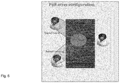
- Figure 6 shows an embodiment of the sound emission apparatus 120 in the first configuration, wherein the audio signal processing apparatus 100 is configured such that the sound emission apparatus 120 emits a first sound beam in a first direction defined by a first listener and a second sound beam in a second direction defined by a second listener.
- Figure 7 shows an embodiment of the sound emission apparatus 120 in the second configuration, wherein the audio signal processing apparatus 100 is configured such that one transducer array of the sound emission apparatus 120 emits a left channel sound beam in a first direction and the other transducer array of the sound emission apparatus 120 emits a right channel sound beam in a second direction, wherein the first and the second direction are defined by the position of a listener.
- Figure 8 shows an embodiment of the sound emission apparatus 120 in the second configuration, wherein the audio signal processing apparatus 100 is configured such that one transducer array of the sound emission apparatus 120 emits a first left channel sound beam in a first direction and a second left channel sound beam in a second direction and the other transducer array of the sound emission apparatus 120 emits a first right channel sound beam in a first direction and a second right channel sound beam in a second direction.
- This could be used, for example, to provide multisport stereo.
- transducer array 123a with the understanding that embodiments of the audio signal processing apparatus 100 can be configured to produce the input signals for the transducers of the transducer arrays 123a,b, 223a,b of the embodiments of the sound emission apparatus 120 described above.
- a sound beam is characterized by a given directivity pattern f ( r, ⁇ , ⁇ ), which defines the acoustic sound pressure generated by the transducer array 123a of the sound emission apparatus 120 on a circumference of a circle with a given radius r, whose center can coincide with the center of the transducer array 123a and which can lie on the equatorial plane.
- the radiation pattern is a function of the angle ⁇ (which identifies a given point on the circumference) and of the frequency ⁇ of the sound to be reproduced.
- each transducer of the transducer array 123a wherein the l -th transducer is located at an angular position ⁇ l , is associated with a given directivity pattern G NF ( r, ⁇ l , ⁇ , ⁇ ), defined in the same manner as the directivity pattern of a sound beam.
- Each sound beam is associated with a given single-channel audio signal x(t), hereafter referred to as "input signal” of the given beam.
- Each beam is associated with a "steering angle" (or beam direction) ⁇ 0 , which identifies the angular coordinate corresponding to the maximum of the absolute value of the radiation pattern associated with that beam.
- the loudspeaker enclosure 121 and the transducer array 123a are arranged on a flat (and ideally infinite) acoustically reflecting wall 340, as shown on the right hand side of figure 9 .
- the directivity coefficients f n depend on the steering direction and characteristics of the beam. In an embodiment, the directivity coefficients f n can be independent of the frequency ⁇ . In an embodiment, the directivity coefficients f n can be chosen to be frequency dependent.
- the angular dependent factor ⁇ ( ⁇ 0 ) advantageously ensures that the pressure level in the steering direction does not vary as a function of the steering angle ⁇ 0 .
- the parameter N controls the width of the beam (the larger N the higher is the beam directivity).
- Other choices than equation (8) for the directivity coefficient f n are possible.
- equations (7) and (8) are the Fourier series representation of symmetric directivity patterns. Indeed, the sound radiated by the sound emission apparatus 120 mounted on a rigid wall can be interpreted as the sound radiated by a full axisymmetric array, wherein each pair of transducers located at ⁇ l and at - ⁇ l , respectively, are driven with the same input signals (hence the symmetry of the directivity pattern with respect to the rigid wall).
- the angular coordinate ⁇ in all equations above varies from 0 to ⁇ radians, because the directivity pattern is defined over a hemi-circumference (as opposed to a circumference for the first configuration of the sound emission apparatus). Also the transducers of the transducer array 123a are arranged on a hemi-circumference. This implies that conventional beamforming methods for circular arrays cannot be applied in this case.
- the sound beam directivity pattern is not rotationally invariant. This means that the shape of the directivity pattern depends on the steering angle ⁇ 0 . This is caused by the presence of the reflective wall 340. For this reason, it is advantageous to include the factor ⁇ ( ⁇ 0 ), in order to ensure that the value of the directivity pattern at ⁇ 0 is unitary.
- the signal processing scheme is based on a pre-knowledge of the Green function G NF ( r, ⁇ l , ⁇ , ⁇ ) (already referred to above as directivity pattern).
- the Green function G NF ( r, ⁇ l , ⁇ , ⁇ ) can be computed by means of numerical methods or measurements.
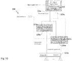
- FIG 10 A schematic diagram of a signal processing scheme implemented in an embodiment of the audio signal processing apparatus 100 for generating a single beam with a single transducer array is shown in figure 10 .
- the sound beam has the directivity pattern given by equation (8).
- the signal x(t) is input to a filter unit or filter bank 103 of N filters.
- a filter unit or filter bank 103 of N filters For the sake of clarity only two of those N filters have been identified by reference signs in figure 10 , namely the filter 103a and the filter 103u.
- the impulse response of the n-th filter of the filters of the filter unit 103 is defined by the following equation or an equation derived therefrom:
- R n t F ⁇ 1 1 ⁇ n r ⁇
- F -1 denotes the inverse Fourier transformation
- ⁇ n characterizes, as a function of radial distance r and frequency ⁇
- the n-th order coefficient is dependent on the shape of the sound emission region 121a of the loudspeaker enclosure 121
- R n ( t ) denotes the impulse response of the n-th filter of the filter unit 103 as a function of time.
- the impulse response of the n-th filter of the filters of the filter unit 103 can comprise a definable regularization parameter ⁇ n (which is generally frequency dependent).
- ⁇ n which is generally frequency dependent
- the filtered audio signals y n (t) are defined as the output of the filter with impulse response R n (t) .
- Each bank of scaling units includes N scaling units, each of which applies a gain coefficient to the corresponding signal filtered audio signal y n (t).
- the gain coefficient depends on the parameters of the desired beam directivity pattern, on the index n , and on the angular coordinate of the given transducer.
- the output signals of a single bank of scaling units are summed by an adder, for instance, the adders 109a and 109w identified in figure 10 , thus generating the output audio signal z l ( t ) that is the input to the t-th transducer of the transducer array 123a.
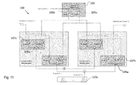
- the sound emission apparatus 120 including the audio signal processing apparatus 100 can also generate multiple sound beams using only a single transducer array, for instance, the transducer array 123a.
- the linear superposition principle can be applied.
- a number of input signals equal to the number of beams should be provided.
- Each of these signals is processed using the signal processing strategy described in the context of figure 10 and the signals z l ( t ) are summed before being fed to the transducers.
- only one filter unit 103 comprising a plurality of filters with in impulse response R n (t) , such as the filter 103a and the filter 103u, is sufficient, as shown in figure 11 .
- FIG 12 shows an embodiment for the case when two transducer arrays are used, for instance, the transducer array 123a and the transducer array 223a.
- each transducer array 123a, 223a can generate an arbitrary number of beams, each of which can be directed to a given target location, for example the region of space occupied by a listener, as illustrated in figure 8 .
- figure 7 represents the case of two beams directed towards a single listener and each beam is generated by one transducer array 123a, 223a.
- the input signals of the two beams can be, for example, the left and right channel of a stereo signal.
- the two transducer arrays 123a, 223a shown in figure 12 generate beams by means of the same input signal, it is sufficient to have one filter unit 103 comprising a plurality of filters, such as the filters 103a and 103u identified in figure 12 .
- a use case for the embodiment shown in figure 12 is shown in figure 7 , namely the case when the left transducer array 123a generates two (or more) beams associated with the left channels of two (or more) different stereo signals and steered towards two (or more) listeners and the right transducer array 223a does the same but for the right channels of the considered stereo signals.
- Another use case for the embodiment shown in figure 12 which is also shown in figure 8 , is given by the same stereo or binaural signal being delivered to two listeners located at two different positions. In this case each transducer array 123a, 223a generates two beams associated with the same signal (left or right channel of a stereo signal) but steered towards different directions.
- the audio signal processing apparatus 100 further comprises a bass enhancement unit, wherein the bass enhancement unit is configured to process each audio input signal 101 individually upstream of the filter unit 103, the plurality of scaling units 107a-v, and the plurality of adders 109a-w.
- a psychoacoustical bass-enhancement unit in combination with the signal processing strategies described above allow a listener to perceive the low-frequency component of a given audio signal, without the sound emission apparatus 100 physically reproducing the lower part of the signal spectrum (or generating little energy in that frequency range).
- the transducer array can generate a band-limited (i.e. without low frequencies) but highly directive beam, but a listener in the sweet-spot of the sound beam will (ideally) perceive a full-range audio signal.
- the processing by the bass enhancement unit is applied to each input signal individually.
- the far-field approximation in the direction ⁇ q , ⁇ q of the field generated by a point source on the rigid hemi-cylinder at location ⁇ , z on the hemi-cylinder is identical to the sound field generated by a plane wave impinging from direction ⁇ q , ⁇ q scattered by the hemi-cylinder and by the hard wall, and measured on the surface of the hemi-cylinder at position ⁇ , z.
- b n ( ⁇ ) i 2 ⁇ H n ′ ⁇
- Equation (16) A possible choice for the radiation pattern is given by equations (8) and (9). This pattern corresponds to an order-truncated spatial Dirac delta function.
Description
- The present invention relates to the field of audio signal processing. In particular, the present invention relates to an audio signal processing apparatus.
- Different configurations and shapes of transducer or loudspeaker arrays for outputting one or more audio signals are known from the prior art.
WO2011/144499 A1 , for instance, discloses a circular loudspeaker array mounted on a cylindrical body. By processing the audio signal in a suitable manner the directivity of the circular loudspeaker array disclosed inWO2011/144499 A1 can be controlled. This process is usually called beamforming. - In the majority of cases, for circular and spherical loudspeaker arrays, beamforming is based on the so-called "mode-matching" approach. The objective is to generate a sound beam with a circular loudspeaker array mounted on a cylindrical body. The array consists of L loudspeakers flush-mounted on the surface of a rigid (ideally infinite) cylinder at the same height. The angular spacing between loudspeakers is assumed to be uniform. The signal ql (ω) driving the l-th loudspeaker at angular coordinate φl , that is required to generate a sound beam steered towards direction φ 0, is given by the following expression (in the frequency domain):

-
US 2007/0269071 A1 discusses non-planar acoustic arrays in which the plurality of transducers lie on a curved surface. The curved surface subtends at least 90 DEG and, in an embodiment is a closed convex surface such as a cylinder. The curvature of the surface allows beams to be directed in a greater variety of directions. Apparatus and methods are discussed in which only certain of the transducers are used for beamforming, in accordance with the position of the transducer relative to the desired beam.EP 1699259 A1 discusses an audio output apparatus having a measuring circuit which measures the levels of at least two sound signals, a sound level adjusting module (a sound level adjusting circuit and a gain control circuit) which adjusts a sound level so as to equal the levels of the sound signals based on the levels measured at the measuring circuit, and an array speaker unit (a delay circuit, a multiplier, an adder, an amplifier and a speaker unit) which emits sounds in accordance with the sound signals outputted from the sound level adjusting module in different directivities respectively. -
US 2013/0223658 A1 discusses a surround sound system for reproducing a spatial sound field in a sound control region within a room having at least one sound reflective surface. The system uses multiple steerable loudspeakers located about the sound control region, each loudspeaker having a plurality of different individual directional response channels being controlled by respective speaker input signals to generate sound waves emanating from the loudspeaker with a desired overall directional response. A control unit connected drives each of the loudspeakers and has pre-configured filters based on measured acoustic transfer functions for the room for filtering the input spatial audio signals to generate the speaker input signals for all the loudspeakers to generate sound waves with co-ordinated overall directional responses that combine together at the sound control region in the form of either direct sound or reflected sound from the reflective surface(s) of the room to reproduce the spatial sound field. -
US 2013/0142337 A1 relates to sonic steerable antennae and their use to achieve a variety of effects. The disclosure comprises a method and apparatus for taking an input signal, replicating it a number of times and modifying each of the replicas before routing them to respective output transducers such that a desired sound field is created. This sound field may comprise a directed beam, focus beam or a simulated origin. Further, "anti-sound" may be directed so as to create nulls (quiet spots) in an already existing sound field. The input signal replicas may also be modified in way which changes their amplitude or they may be filtered to provide the desired delaying. -
EP 1061769 A2 discusses a loudspeaker which comprises: a plurality of octant loudspeakers which are pivotally connected with each other; each octant loudspeaker having a vertical pivotal wall provided with a bracket having a pair of projections, the octant loudspeaker including a plurality of loudspeaker drivers, the octant loudspeaker being an octant hollow casing made of fibrous glass reinforced plastics and having a plurality of openings on a baffle for accommodating a loudspeaker driver, said loudspeaker driver including a permanent magnet and a diaphragm having a voice coil bonded thereto and an electrical terminal provided on a horizontal face of the housing; and a square strut having T-shaped notches on each side face which receive the projections of the brackets for mounting the octant loudspeakers on the strut. - It is an object of the invention to provide an innovative audio signal processing apparatus .
- Aspects of the invention are defined in the independent claims. Preferred embodiments of the invention are defined in the dependent claims thereof.
- According to a first aspect, an audio signal processing apparatus for processing an input audio signal is provided, comprising a filter unit comprising a plurality of filters, each filter configured to filter the input audio signal to obtain a plurality of filtered audio signals, each filter designed according to a mode matching beamforming being applied to a surface of a half revolution, a plurality of scaling units, each scaling unit configured to scale the plurality of filtered audio signals using a plurality of gain coefficients to obtain a plurality of scaled filtered audio signals, and a plurality of adders, each adder configured to combine the plurality of scaled filtered audio signals, thereby providing an output audio signal for producing a sound field having a beam directivity pattern defined by the plurality of gain coefficients. A surface of a half revolution is defined by rotating a generatrix by 180° around a straight line, i.e. an axis, in the plane of the generatrix. In case of a generatrix in the form of a straight line running parallel to the axis the surface of a half revolution is the outer surface of a half cylinder. Herein extended mode matching beamforming is defined as an extension of conventional mode matching beamforming to such a surface of a half revolution.
- Thus, an innovative audio signal processing apparatus is provided.
- In a first possible implementation form of the audio signal processing apparatus according to the first aspect, the impulse response of an n-th filter of the plurality of filters is defined by the following equation or an equation derived therefrom:

- In a second possible implementation form of the audio signal processing apparatus according to the first implementation form the impulse response of the n-th filter is defined by the following equation or an equation derived therefrom:

- In a third possible implementation form of the audio signal processing apparatus according to the first or the second implementation form of the first aspect of the invention, Γ n is defined by the following equation or an equation derived therefrom:


- In a fourth possible implementation form of the audio signal processing apparatus according to any one of the first to third implementation form of the first aspect of the invention, the output audio signal for the l-th transducer of the transducer array is defined by the following equation or an equation derived therefrom:

- In a fifth possible implementation form of the audio signal processing apparatus according to the fourth implementation form of the first aspect, the n-th gain coefficient for the l-th transducer of the transducer array is defined by the following equation or an equation derived therefrom:

- In a sixth possible implementation form of the audio signal processing apparatus according to the fifth implementation form of the first aspect of the invention, the beam directivity pattern is a single beam in a direction defined by an angle φ 0 and wherein the n-th directivity coefficient fn is defined by the following equation or an equation derived therefrom:


- In a seventh possible implementation form of the audio signal processing apparatus according to any one of the fourth to sixth implementation form of the first aspect of the invention, the beam directivity pattern is defined by multiple beams in respective directions defined by a respective angle φj and wherein the output audio signal zl (t) for the l-th transducer of the transducer array is given by the following equation or an equation derived therefrom:

- In an eighth possible implementation form of the audio signal processing apparatus according to the first aspect as such or according to any one of the preceding implementation forms, the filter unit, the plurality of scaling units and the plurality of adders are configured to process at least two audio input audio signals, thereby providing a stereo output audio signal for producing a stereo sound field having the beam directivity pattern defined by the plurality of gain coefficients.
- In a ninth possible implementation form of the audio signal processing apparatus according to the first aspect as such or according to any one of the preceding implementation forms, the filter unit, the plurality of scaling units and the plurality of adders are further configured to provide a further output audio signal for producing a further sound field, via a half axisymmetric loudspeaker array, having a further beam directivity pattern defined by the plurality of gain coefficients.
- In a tenth possible implementation form of the audio signal processing apparatus according to the first aspect as such or according to any one of the preceding implementation forms, the audio signal processing apparatus further comprises a bass enhancement unit, wherein the bass enhancement unit is configured to process each audio input signal individually upstream of the filter unit, the plurality of scaling units, and the plurality of adders.
- In an eleventh possible implementation form of the audio signal processing apparatus according to the first aspect as such or according to any one of the preceding implementation forms, the audio signal processing apparatus further comprises a filter network for dividing the input audio signal into two or more divided input audio signals of differing frequency bandwidths, thereby providing at least a first and second input audio signal, and a further filter unit, a further plurality of scaling units, and a further plurality of adders for processing the second input audio signal, thereby providing a second output audio signal for producing the sound field having the beam directivity pattern defined by the plurality of gain coefficients.
- Further embodiments of the invention will be described with respect to the following figures, in which:
-
Fig. 1 shows a schematic diagram illustrating an audio signal processing apparatus according to an embodiment of the invention and a sound emission apparatus according to an example not covered by the claimed invention; -
Fig. 2 shows a perspective view of a sound emission apparatus according to an example not covered by the claimed invention in a first configuration and in a second configuration; -
Fig. 3 shows a perspective view of a sound emission apparatus according to an example not covered by the claimed invention in a second configuration; -
Fig. 4 shows a perspective view of a sound emission apparatus according to an example not covered by the claimed invention in a first configuration; -
Fig. 5 shows a perspective view of a sound emission apparatus according to an example not covered by the claimed invention in a first configuration; -
Fig. 6 shows a schematic top view of an implementation scenario for a sound emission apparatus according to an example not covered by the claimed invention in a first configuration; -
Fig. 7 shows a schematic top view of an implementation scenario for a sound emission apparatus according to an example not covered by the claimed invention in a second configuration; -
Fig. 8 shows a schematic top view of an implementation scenario for a sound emission apparatus according to an example not covered by the claimed invention in a second configuration; -
Fig. 9 shows a schematic top view of a sound emission apparatus according to an example not covered by the claimed invention in a first configuration and in a second configuration; -
Fig. 10 shows a schematic diagram illustrating an audio signal processing apparatus according to an embodiment; -
Fig. 11 shows a schematic diagram illustrating an audio signal processing apparatus according to an embodiment; and -
Fig. 12 shows a schematic diagram illustrating an audio signal processing apparatus according to an embodiment. - As far as possible, identical reference signs have been used in the different figures for identical or at least functionally equivalent features.
- In the following detailed description, reference is made to the accompanying drawings, which form a part of the disclosure, and in which are shown, by way of illustration, specific aspects in which the present invention may be practiced. It is understood that other aspects may be utilized and structural or logical changes may be made without departing from the scope of the present invention. The following detailed description, therefore, is not to be taken in a limiting sense, as the scope of the present invention is defined by the appended claims. For instance, it is understood that the features of the various exemplary aspects described herein may be combined with each other, unless specifically noted otherwise.
-
Figure 1 shows schematically an audiosignal processing apparatus 100 according to an embodiment. - The audio
signal processing apparatus 100 is configured to process aninput audio signal 101. As indicated infigure 1 , theinput audio signal 101 can comprise more than one input audio signal or channel, for instance, the left channel and the right channel of a stereo input audio signal. - The audio
signal processing apparatus 100 comprises afilter unit 103 having a plurality offilters 103a-u. Thefilters 103a-u of thefilter unit 103 are configured to filter theinput audio signal 101 to obtain a plurality of filteredaudio signals 105 and are designed according to an extended mode matching beamforming applied to a surface of a half revolution, wherein the surface partially characterizes the shape of a loudspeaker enclosure, such as theloudspeaker enclosure 121 shown infigure 1 . A surface of a half revolution is defined by rotating a generatrix by 180° around a straight line, i.e. an axis, in the plane of the generatrix. In case of a generatrix in the form of a straight line running parallel to the axis the surface of a half revolution is the outer surface of a half cylinder. Herein extended mode matching beamforming is defined as an extension of conventional mode matching beamforming to such a surface of a half revolution. - The audio
signal processing apparatus 100 further comprises a plurality of scalingunits 107a-v, wherein eachscaling unit 107a-v is configured to scale the plurality of filtered audio signals 105 (provided by the filter unit 103) using a plurality of gain coefficients to obtain a plurality of scaled filtered audio signals 108. - The audio
signal processing apparatus 100 further comprises a plurality ofadders 109a-w, wherein eachadder 109a-w is configured to combine the plurality of scaled filteredaudio signals 108, thereby providing anoutput audio signal 111 for producing a sound field having a beam directivity pattern defined by the plurality of gain coefficients. As indicated infigure 1 , theoutput audio signal 111 can generally comprise a plurality of output audio signals. In an embodiment, eachadder 109a-w can be configured to add the plurality of scaled filtered audio signals 108. In an embodiment, eachadder 109a-w can be configured to combine the plurality of scaled filteredaudio signals 108 for providing arespective output signal 111 to each transducer of a transducer array, for instance, the transducer array 123 shown infigure 1 . Generally, the number of transducers corresponds to the numbers ofadders 109a-w. -
Figure 1 , furthermore, shows schematically asound emission apparatus 120 in communication with the audiosignal processing apparatus 100. Although shown as a separate component infigure 1 , in an embodiment the audiosignal processing apparatus 100 can be part of thesound emission apparatus 120. - The
sound emission apparatus 120 comprises aloudspeaker enclosure 121 having asound emission section 121a and arear section 121b, wherein thesound emission section 121a is coupled to or integral with therear section 121b. Generally, thesound emission section 121a defines a surface of a half revolution about an axis extending along a length of theloudspeaker enclosure 121. In the schematic diagram offigure 1 this axis runs normal to the plane defined byfigure 1 . - Moreover, the
sound emission apparatus 120 comprises at least onetransducer array 123a comprising a plurality of transducers or loudspeakers that can be mounted on thesound emission section 121a of theloudspeaker enclosure 121, wherein a plane passing through thetransducer array 123a is orthogonal to the axis. In the schematic diagram offigure 1 , the plane passing through thetransducer array 123a coincides with the plane defined byfigure 1 . As indicated infigure 1 , thetransducer array 123a is curved such that thetransducer array 123a conforms to the curvature of the surface of the half revolution. - In an embodiment, the transducers of the
transducer array 123a can be flush-mounted on the surface of thesound emission section 121a of theloudspeaker enclosure 121. To this end, in an embodiment one or more apertures can be provided in thesound emission section 121a of theloudspeaker enclosure 121 for accommodating thetransducer array 123a. In an embodiment of thesound emission apparatus 120, further apertures can be provided in theloudspeaker enclosure 121 providing, for instance, for acoustic vents. - In an embodiment, the transducers of the
transducer array 123a can be combined with waveguides integrated in thesound emission apparatus 120. In this embodiment, each transducer of thetransducer array 123a can be mounted in the interior of theloudspeaker enclosure 121 and a waveguide can connect a diaphragm of each transducer with a sound emission port on thesound emission section 121a, i.e. with the exterior of thesound emission apparatus 120. - In the following, further implementation forms, embodiments and aspects of the audio
signal processing apparatus 100 and thesound emission apparatus 120 will be described. -
Figure 2 shows a perspective view of thesound emission apparatus 120 according to an embodiment in a first configuration and in a second configuration. In comparison to thesound emission apparatus 120 shown infigure 1 , thesound emission apparatus 120 shown infigure 2 comprises in addition to theloudspeaker enclosure 121 afurther loudspeaker enclosure 221 comprising afurther transducer array 223a. - In an embodiment, the
further loudspeaker enclosure 221 that generally can have a half axisymmetric shape comprises asound emission section 221a and a rear section 221b. In an embodiment thesound emission section 221a is coupled to or integral with the rear section 221b and generally defines a further surface of the half revolution about a further axis extending along a length of thefurther loudspeaker enclosure 221. In an embodiment, thefurther transducer array 223a is mounted on thesound emission section 221a of thefurther loudspeaker enclosure 221, wherein a further plane passing through thefurther transducer array 223a is orthogonal to the further axis. In an embodiment, thefurther transducer array 223a is curved such that thefurther transducer array 223a conforms to the curvature of the further surface of the half revolution. In an alternative embodiment, the further transducer array can be mounted within thefurther loudspeaker enclosure 221 and connected to a further array of waveguides defining a further array of sound emission ports in thesound emission section 221a of thefurther loudspeaker enclosure 221, wherein a further plane passing through the further array of sound emission ports is orthogonal to the further axis and the further array of sound emission ports being curved such that the further array of sound emission ports conforms to the curvature of the further surface of the half revolution. - In an embodiment, the rear section 221b of the
further loudspeaker enclosure 221 is configured to be coupled to therear section 121b of theloudspeaker enclosure 121 thereby generally defining an axis-symmetric shape. This is shown on the left hand side offigure 2 , wherein the rear section 221b of thefurther loudspeaker enclosure 221 is coupled to therear section 121b of theloudspeaker enclosure 121, thereby defining a first configuration of thesound emission apparatus 120. On the right hand side offigure 2 , theloudspeaker enclosure 121 containing thetransducer array 123a and thefurther loudspeaker enclosure 221 containing thefurther transducer array 223a are separated from each other, thereby defining a second configuration of thesound emission apparatus 120. - As illustrated in
figure 2 , in an embodiment thetransducer array 123a substantially spans the width of thesound emission section 121a of theloudspeaker enclosure 121 and thefurther transducer array 223a substantially spans the width of thesound emission section 221a of thefurther loudspeaker enclosure 221. - As can be taken from
figure 2 , theloudspeaker enclosure 121 and thefurther loudspeaker enclosure 221 have the shape of a half cylinder. Generally, theloudspeaker enclosure 121 and thefurther loudspeaker enclosure 221 can define one half of an axis-symmetric shape, i.e. one half of a surface or solid of revolution, for instance, one half of a cone. - In an embodiment, the
first transducer array 123a can be arranged on thesound emission section 121a of theloudspeaker enclosure 121 at the same height as thefurther transducer array 223a on thesound emission section 221a of thefurther loudspeaker enclosure 221. In an embodiment, the angular spacing Δφ between neighboring transducers of thetransducer array 123a and thefurther transducer array 223a can be uniform. This means that if thetransducer array 123a and thefurther transducer array 223a comprise in an embodiment 2L transducers, wherein the angular spacing Δφ between neighboring transducers is given by the following equation:
- For the first configuration of the
sound emission apparatus 120 shown on the left hand side offigure 2 , where therear section 121b of theloudspeaker enclosure 121 is coupled to the rear section of thefurther loudspeaker enclosure 221, the angular coordinate φl that identifies the position of the l-th transducer is given by:
- For the second configuration of the
sound emission apparatus 120 shown on the right hand side offigure 2 , the angular coordinate of the l-th transducer for a given transducer array is given by:
-
Figure 3 shows a perspective view of thesound emission apparatus 120 according to an embodiment in a second configuration, i.e. in a configuration, where theloudspeaker enclosure 121 including thetransducer array 123a and theloudspeaker enclosure 221 including thetransducer array 223a are physically separated from another. In the exemplary embodiment shown infigure 3 , theloudspeaker enclosure 121 including thetransducer array 123a and theloudspeaker enclosure 221 including thetransducer array 223a are mounted on awall 340 with their respective rear sections. In an embodiment, thesound emission apparatus 120 can be used together with adisplay 330, which in the exemplary embodiment shown infigure 3 is arranged between theloudspeaker enclosure 121 including thetransducer array 123a and theloudspeaker enclosure 221 including thetransducer array 223a. -
Figure 4 shows a perspective view of thesound emission apparatus 120 according to an embodiment in a first configuration, i.e. in a configuration, where theloudspeaker enclosure 121 including thetransducer array 123a and theloudspeaker enclosure 221 including thetransducer array 223a are coupled together by means of their respective rear sections. Thesound emission apparatus 120 shown infigure 4 differs from thesound emission apparatus 120 shown infigures 2 and3 primarily in two aspects. Firstly, theloudspeaker enclosure 121 and theloudspeaker enclosure 221 of thesound emission apparatus 120 shown infigure 4 together do not define the shape of a cylinder, as in the case of the embodiment shown infigure 2 , but an axis-symmetric bottle-like shape. Secondly, theloudspeaker enclosure 121 and theloudspeaker enclosure 221 of thesound emission apparatus 120 shown infigure 4 each contain two transducer arrays at different heights, namely thetransducer arrays transducer arrays first transducer array sound emission apparatus 120 and a second plane passing through thesecond transducer array - In an embodiment, the
transducer arrays transducer arrays - An ideal configuration would include an infinite number of circular transducer arrays, such that each combination of transducer arrays of radius r(ω) is used for a single frequency ω. The radius is chosen such that the product ω·r(ω) is kept constant. It can be shown that in this ideal case the impulse response of the filters Rn is constant. However, such an ideal configuration is clearly not practical and in practice generally a finite number of transducer arrays should be chosen. For instance, in the embodiment shown in
figure 4 thefirst transducer arrays second transducer arrays sound emission apparatus 120 is configured to provide a first band-limited audio signal with a first frequency range approximately in the vicinity of an angular frequency ω1, and provide a second band-limited audio signal with a second frequency range approximately in the vicinity of an angular frequency ω2, wherein the angular frequencies ω1 and ω2 are given by the following equation or an equation derived therefrom:
values - Thus, by means of the present invention it is possible to design different transducer arrays optimized for different frequency ranges. In this case, the input signal to a given beam can be separated into a number of frequency bands (using for example a multi-band crossover network), each of which corresponds to the input signal to a given combination of transducer arrays. Thus, in an embodiment of the audio
signal processing apparatus 100, the audiosignal processing apparatus 100 further comprises a filter network for dividing theinput audio signal 101 into two or more divided input audio signals of differing frequency bandwidths, thereby providing at least a first and second input audio signal, and a further filter unit, a further plurality of scaling units, and a further plurality of adders for processing the second input audio signal, thereby providing a second output audio signal for producing the sound field having the beam directivity pattern defined by the plurality of gain coefficients. -
Figure 5 shows a perspective view of thesound emission apparatus 120 according to an embodiment in a first configuration, i.e. in a configuration, where theloudspeaker enclosure 121 including thetransducer array 123a and theloudspeaker enclosure 221 including thetransducer array 223a are coupled together by means of their respective rear sections. Thesound emission apparatus 120 shown infigure 5 differs from thesound emission apparatus 120 shown in the previous figures primarily in that thefirst transducer arrays second transducer arrays figure 5 are arranged immediately below thefirst transducer arrays first transducer arrays second transducer arrays sound emission apparatus 120, the angular offset can be about half of the angular spacing between neighboring transducers of thefirst transducer arrays sound emission apparatus 120 by increasing the frequency limit above which the beam directional pattern is corrupted by spatial aliasing. - In an embodiment, the audio
signal processing apparatus 100 and the below described further embodiments thereof implement a signal processing strategy to produce the input signals for the transducers of the transducer array(s) 123a,b, 223a,b of thesound emission apparatus 120 for generating one or more directed sound beams.Figures 6 to 8 show exemplary implementation scenarios of thesound emission apparatus 120, which can be achieved by different signal processing strategies implemented in the audiosignal processing apparatus 100, as will be described in more detail further below. -
Figure 6 shows an embodiment of thesound emission apparatus 120 in the first configuration, wherein the audiosignal processing apparatus 100 is configured such that thesound emission apparatus 120 emits a first sound beam in a first direction defined by a first listener and a second sound beam in a second direction defined by a second listener. -
Figure 7 shows an embodiment of thesound emission apparatus 120 in the second configuration, wherein the audiosignal processing apparatus 100 is configured such that one transducer array of thesound emission apparatus 120 emits a left channel sound beam in a first direction and the other transducer array of thesound emission apparatus 120 emits a right channel sound beam in a second direction, wherein the first and the second direction are defined by the position of a listener. -
Figure 8 shows an embodiment of thesound emission apparatus 120 in the second configuration, wherein the audiosignal processing apparatus 100 is configured such that one transducer array of thesound emission apparatus 120 emits a first left channel sound beam in a first direction and a second left channel sound beam in a second direction and the other transducer array of thesound emission apparatus 120 emits a first right channel sound beam in a first direction and a second right channel sound beam in a second direction. This could be used, for example, to provide multisport stereo. - In the following reference will be made primarily to the
transducer array 123a with the understanding that embodiments of the audiosignal processing apparatus 100 can be configured to produce the input signals for the transducers of thetransducer arrays 123a,b, 223a,b of the embodiments of thesound emission apparatus 120 described above. - Typically, a sound beam is characterized by a given directivity pattern f(r, φ, ω), which defines the acoustic sound pressure generated by the
transducer array 123a of thesound emission apparatus 120 on a circumference of a circle with a given radius r, whose center can coincide with the center of thetransducer array 123a and which can lie on the equatorial plane. The radiation pattern is a function of the angle φ (which identifies a given point on the circumference) and of the frequency ω of the sound to be reproduced. Also each transducer of thetransducer array 123a, wherein the l-th transducer is located at an angular position φl, is associated with a given directivity pattern GNF (r, φl , φ, ω), defined in the same manner as the directivity pattern of a sound beam. - Each sound beam is associated with a given single-channel audio signal x(t), hereafter referred to as "input signal" of the given beam. Each beam is associated with a "steering angle" (or beam direction) φ 0, which identifies the angular coordinate corresponding to the maximum of the absolute value of the radiation pattern associated with that beam.
- For the following mathematical derivation it is assumed that the
loudspeaker enclosure 121 and thetransducer array 123a are arranged on a flat (and ideally infinite) acoustically reflectingwall 340, as shown on the right hand side offigure 9 . The directivity pattern of the l-th transducer located at φl can be expressed using the following equation:
transducer array 123a. An analytical expression for the coefficients Γ n (r, ω) is derived in the mathematical appendix further below for the case of the transducers of thetransducer array 123a being flush-mounted on the surface of thesound emission section 121a, which is configured as a rigid hemi-cylinder. - The directivity pattern of a sound beam (also referred to as beam directivity pattern) can be expressed using the following equation:

- Typically, the directivity coefficients fn depend on the steering direction and characteristics of the beam. In an embodiment, the directivity coefficients fn can be independent of the frequency ω. In an embodiment, the directivity coefficients fn can be chosen to be frequency dependent.
- In an embodiment of the audio
signal processing apparatus 100, the beam directivity pattern is a single beam in a direction defined by an angle φ 0 (also referred to as steering angle), wherein the n-th directivity coefficient fn is defined by the following equation or an equation derived therefrom:

- The angular dependent factor γ(φ 0) advantageously ensures that the pressure level in the steering direction does not vary as a function of the steering angle φ 0. The parameter N controls the width of the beam (the larger N the higher is the beam directivity). Other choices than equation (8) for the directivity coefficient fn are possible.
- Above equations (7) and (8) are the Fourier series representation of symmetric directivity patterns. Indeed, the sound radiated by the
sound emission apparatus 120 mounted on a rigid wall can be interpreted as the sound radiated by a full axisymmetric array, wherein each pair of transducers located at φl and at -φl , respectively, are driven with the same input signals (hence the symmetry of the directivity pattern with respect to the rigid wall). - Note that the angular coordinate φ in all equations above varies from 0 to π radians, because the directivity pattern is defined over a hemi-circumference (as opposed to a circumference for the first configuration of the sound emission apparatus). Also the transducers of the
transducer array 123a are arranged on a hemi-circumference. This implies that conventional beamforming methods for circular arrays cannot be applied in this case. - The mathematical derivation of the new approach proposed by the present invention is described in detail in the mathematical appendix further below and can be regarded as a reformulation of the mode-matching approach specifically derived for a hemi-circular arrangement of transducers. As will become clear from the below, the derivation no longer involves the Fourier series, as in above equation (1), but the Discrete Cosine Transform, as defined in equation (A.23).
- It should be also emphasized that, as opposed to the case of a circular array, the sound beam directivity pattern is not rotationally invariant. This means that the shape of the directivity pattern depends on the steering angle φ 0. This is caused by the presence of the
reflective wall 340. For this reason, it is advantageous to include the factor γ(φ 0), in order to ensure that the value of the directivity pattern at φ 0 is unitary. - The signal processing scheme is based on a pre-knowledge of the Green function GNF (r, φl, φ, ω) (already referred to above as directivity pattern). In an embodiment, the Green function GNF (r, φl , φ, ω) can be computed by means of numerical methods or measurements. An analytical expression of the Green function GNF (r, φl , φ, ω) for the embodiment, where the transducers of the
transducer array 123a are flush-mounted on the surface of thesound emission section 121a, which for the analytical derivation is assumed to have the shape of the surface of an infinite and rigid hemi-cylinder, and where theapparatus 120 itself is mounted on an infinite rigid wall is disclosed in the mathematical appendix further below. - A schematic diagram of a signal processing scheme implemented in an embodiment of the audio
signal processing apparatus 100 for generating a single beam with a single transducer array is shown infigure 10 . In an embodiment, the sound beam has the directivity pattern given by equation (8). The signal x(t) is input to a filter unit orfilter bank 103 of N filters. For the sake of clarity only two of those N filters have been identified by reference signs infigure 10 , namely thefilter 103a and thefilter 103u. - In an embodiment of the audio
signal processing apparatus 100, the impulse response of the n-th filter of the filters of thefilter unit 103 is defined by the following equation or an equation derived therefrom:
transducer array 123a conforming to the curvature of a surface of a full revolution comprising the surface of the half revolution, the n-th order coefficient is dependent on the shape of thesound emission region 121a of theloudspeaker enclosure 121, and Rn (t) denotes the impulse response of the n-th filter of thefilter unit 103 as a function of time. As the person skilled in the art will appreciate, equation (10) is a simplified version of the following equation:
- In a further embodiment, the impulse response of the n-th filter of the filters of the
filter unit 103 can comprise a definable regularization parameter βn (which is generally frequency dependent). Thus, in an embodiment of the audiosignal processing apparatus 100, the impulse response of the n-th filter of thefilter unit 103 is defined by the following equation or an equation derived therefrom:
- As will be described in more detail in the mathematical appendix further below, in an embodiment of the audio
signal processing apparatus 100, Γ n is defined by the following equation or an equation derived therefrom:

- The filtered audio signals yn(t) are defined as the output of the filter with impulse response Rn(t). The signals yn(t), n=0, 1,...,N are input to L banks of gains or scaling units (one bank of gains for each source of the sub-array). For the sake of clarity only two scaling units or gains have been identified by reference signs in
figure 10 , namely thescaling units 107a and thescaling unit 107v. Each bank of scaling units includes N scaling units, each of which applies a gain coefficient to the corresponding signal filtered audio signal yn(t). - In an embodiment, the n-th gain coefficient, i.e. the gain coefficient provided by the n-th scaling unit, for the l-th transducer of the
transducer array 123a is defined by the following equation or an equation derived therefrom:
transducer array 123a, and fn characterizes the n-th coefficient of the Fourier series or Fourier cosine series describing a desired beam directivity pattern as a function of the radiation angle. As the person skilled in the art will appreciate, the gain coefficient depends on the parameters of the desired beam directivity pattern, on the index n, and on the angular coordinate of the given transducer. The output signals of a single bank of scaling units are summed by an adder, for instance, theadders figure 10 , thus generating the output audio signal zl (t) that is the input to the t-th transducer of thetransducer array 123a. - Thus, in an embodiment of the audio
signal processing apparatus 100, the output audio signal zl (t) for the l-th transducer of thetransducer array 123a is defined by the following equation or an equation derived therefrom:
transducer array 123a. - In an embodiment, the
sound emission apparatus 120 including the audiosignal processing apparatus 100 can also generate multiple sound beams using only a single transducer array, for instance, thetransducer array 123a. To this end, in an embodiment the linear superposition principle can be applied. A number of input signals equal to the number of beams should be provided. Each of these signals is processed using the signal processing strategy described in the context offigure 10 and the signals zl (t) are summed before being fed to the transducers. In an embodiment, it is possible to generate multiple beams that are associated with the same input signal x(t), but are steered to different directions (or, more generally, have different characteristics). In this case only onefilter unit 103 comprising a plurality of filters with in impulse response Rn(t), such as thefilter 103a and thefilter 103u, is sufficient, as shown infigure 11 . - Thus, in an embodiment of the audio
signal processing apparatus 100, the beam directivity pattern is defined by multiple beams in respective directions defined by a respective angle φj and the output audio signal zl (t) for the l-th transducer of thetransducer array 123a is given by the following equation or an equation derived therefrom:
-
Figure 12 shows an embodiment for the case when two transducer arrays are used, for instance, thetransducer array 123a and thetransducer array 223a. In an embodiment, eachtransducer array figure 8 . As already described above,figure 7 represents the case of two beams directed towards a single listener and each beam is generated by onetransducer array transducer arrays figure 12 generate beams by means of the same input signal, it is sufficient to have onefilter unit 103 comprising a plurality of filters, such as thefilters figure 12 . - A use case for the embodiment shown in
figure 12 is shown infigure 7 , namely the case when theleft transducer array 123a generates two (or more) beams associated with the left channels of two (or more) different stereo signals and steered towards two (or more) listeners and theright transducer array 223a does the same but for the right channels of the considered stereo signals. Another use case for the embodiment shown infigure 12 , which is also shown infigure 8 , is given by the same stereo or binaural signal being delivered to two listeners located at two different positions. In this case eachtransducer array - The directivity of a sound beam at low frequencies is generally limited by the physical size of the transducer array. For instance, the generation of a highly directive low-frequency bream with a small transducer array requires that the transducers a driven by signals with very large amplitude, which may degrade the performance of the
sound emission apparatus 120 when this departs form ideal conditions. Thus, in an embodiment of the audiosignal processing apparatus 100, the audiosignal processing apparatus 100 further comprises a bass enhancement unit, wherein the bass enhancement unit is configured to process eachaudio input signal 101 individually upstream of thefilter unit 103, the plurality of scalingunits 107a-v, and the plurality ofadders 109a-w. A psychoacoustical bass-enhancement unit in combination with the signal processing strategies described above allow a listener to perceive the low-frequency component of a given audio signal, without thesound emission apparatus 100 physically reproducing the lower part of the signal spectrum (or generating little energy in that frequency range). With this approach the transducer array can generate a band-limited (i.e. without low frequencies) but highly directive beam, but a listener in the sweet-spot of the sound beam will (ideally) perceive a full-range audio signal. In an embodiment, the processing by the bass enhancement unit is applied to each input signal individually. - In the following mathematical appendix, some of the equations used above will be derived and/or explained in more detail. Firstly, the analytical expression is derived for the radiation pattern of an ideal omnidirectional transducer or loudspeaker (ideal monopole) flush-mounted on the surface of an infinite rigid hemi-cylinder arranged on a rigid, infinite wall, as shown on the right hand side of
figure 9 . To that end, an equivalent scattering approach is used. More specifically, the far-field approximation in the direction φq, θq of the field generated by a point source on the rigid hemi-cylinder at location φ, z on the hemi-cylinder is identical to the sound field generated by a plane wave impinging from direction φq, θq scattered by the hemi-cylinder and by the hard wall, and measured on the surface of the hemi-cylinder at position φ, z. - It is assumed that the sound field of interest is defined in the hemispace with y > 0 and is bounded by a rigid wall on the xz-plane. This imposes the following Neumann boundary condition on the field:

- The field due to a plane wave impinging from an angle φq, θq and reflected by a rigid wall located at φ = 0, π (this corresponds to a wall on the plane y=0). This is given by the linear summation of two plane waves from φq, θq and from -φq, θq, respectively, in the half-space defined by 0 ≤ φ ≤ π. In polar coordinates and for z = 0 this is given by:


- This implies that the field is symmetric with respect to the plane defined by the wall. The Fourier series in equation (A.2) can therefore be substituted by the following cosine series:


- More generally, any sound field due to waves impinging from
directions 0 ≤ φ ≤ π (and that satisfies the homogeneous Helmholtz equation in the half-space y>0) and the corresponding scattered and total field in the presence of a rigid plane y=0 can be represented as:


- For a plane wave impinging from φq, θq this is given by:

- Now, the problem of scattering of a field due to waves impinging from
directions 0 ≤ φ ≤ π is studied for a half rigid infinite cylinder being placed on a rigid wall, as infigure 9 . To that end a modified Green function is used. The Green function of the Helmholtz equation that satisfies the Neumann boundary condition (A.1) is given by a free field Green function plus its image source, that is:


- In the presence of a scatterer with boundary S, the scattered field can be represented by a modified single layer potential:


- For the case under consideration S = {r : |r| = R, 0 ≤ φ ≤ π}, that is the surface of the rigid hemi-cylinder. In this case the scattered field can be regarded as the field generated by a radiating cylinder with a vibration pattern symmetrical with respect to the plane y=0 and can be therefore expressed by means of the following series of cosines and Hankel functions:

- Applying the Neumann boundary condition on the surface of the rigid hemi-cylinder one obtains:


- If the field is evaluated on the boundary of the scatterer, that is at r=R, the Wronskian relation Hn'(ξ)Jn (ξ) - Hn (ξ)Jn'(ξ) = i2/(πξ) can be used, thus obtaining the following expression for the total (incident+scattered) field:

- The function bn (ξ) is defined as follows:

- For a plane wave impinging from φq, θq, combining the results above with equation (A.10) the following final result is obtained:

- This is the radiation pattern of a transducer located on the rigid hemi-cylinder at location R, φ, z. Evaluating this result for z=0 (i.e. for θq = π/2) and comparing with equation (7) one obtains:

- Secondly, the mathematical formulae defining the signal processing blocks for synthesizing a far-field radiation pattern f(φ), as given by equation (8) with a sub-array of L uniformly spaced transducers are derived.
- The spatial spectrum of the target radiation pattern is chosen to be frequency independent and limited to the order N=L-1. Recalling that


- Both sides of equation (A.22) are multiplied by m cos(mφ)/π and integrated between 0 and π, thus obtaining:


- This approach provides an exact result only if the contribution of the order n≥L in equation (7) is negligible. Otherwise, the reproduced radiation pattern will be affected by spatial aliasing. The regularized version of equation (A.26) is computed using equation (15) and is given by:

- Applying the inverse Fourier transform to this result and convolving it with x(t) yields equation (16). A possible choice for the radiation pattern is given by equations (8) and (9). This pattern corresponds to an order-truncated spatial Dirac delta function. The constant γ(φ 0) may be chosen so that f(φ 0) = 1 and is therefore given by equation (10). Combining all results above we obtain:


- This is the mathematical representation of the signal processing scheme illustrated in
figures 10 to 12 . - While a particular feature or aspect of the disclosure may have been disclosed with respect to only one of several implementations or embodiments, such feature or aspect may be combined with one or more other features or aspects of the other implementations or embodiments as may be desired and advantageous for any given or particular application. Furthermore, to the extent that the terms "include", "have", "with", or other variants thereof are used in either the detailed description or the claims, such terms are intended to be inclusive in a manner similar to the term "comprise". Also, the terms "exemplary", "for example" and "e.g." are merely meant as an example, rather than the best or optimal. The terms "coupled" and "connected", along with derivatives may have been used. It should be understood that these terms may have been used to indicate that two elements cooperate or interact with each other regardless whether they are in direct physical or electrical contact, or they are not in direct contact with each other.
- Although the elements in the following claims are recited in a particular sequence with corresponding labeling, unless the claim recitations otherwise imply a particular sequence for implementing some or all of those elements, those elements are not necessarily intended to be limited to being implemented in that particular sequence.
- Many alternatives, modifications, and variations will be apparent to those skilled in the art in light of the above teachings. Of course, those skilled in the art readily recognize that there are numerous applications of the invention beyond those described herein. While the present invention has been described with reference to one or more particular embodiments, those skilled in the art recognize that many changes may be made thereto without departing from the scope of the present invention, as it is defined in the claims.
Claims (12)
- An audio signal processing apparatus (100) for processing an input audio signal (101), the audio signal processing apparatus (100) comprising:a filter unit (103) comprising a plurality of filters (103a-u), each filter (103a-u) configured to filter the input audio signal (101) to obtain a plurality of filtered audio signals (105), each filter (103a-u) designed according to a mode matching beamforming being applied to a surface of a half revolution;a plurality of scaling units (107a-v), each scaling unit (107a-v) configured to scale the plurality of filtered audio signals (105) using a plurality of gain coefficients to obtain a plurality of scaled filtered audio signals (108); anda plurality of adders (109a-w), each adder (109a-w) configured to combine the plurality of scaled filtered audio signals (108), thereby providing an output audio signal (111) for producing a sound field having a beam directivity pattern defined by the plurality of gain coefficients.
- The audio signal processing apparatus (100) of claim 1,
wherein the impulse response of an n-th filter of the plurality of filters (103a-u) is defined by the following equation or an equation derived therefrom:
- The audio signal processing apparatus (100) of claim 2, wherein the impulse response of the n-th filter (103a-i) is defined by the following equation or an equation derived therefrom:

- The audio signal processing apparatus (100) of claim 2 or 3, wherein Γ n is defined by the following equation or an equation derived therefrom:


- The audio signal processing apparatus (100) of any one of claims 2 to 4, wherein the output audio signal (111) for the l-th transducer of the transducer array (123a,b, 223a,b) is defined by the following equation or an equation derived therefrom:

- The audio signal processing apparatus (100) of claim 5, wherein the n-th gain coefficient for the l-th transducer of the transducer array (123a,b, 223a,b) is defined by the following equation or an equation derived therefrom:

- The audio signal processing apparatus (100) of claim 6, wherein the beam directivity pattern is a single beam in a direction defined by an angle φ 0 and wherein the n-th directivity coefficient fn is defined by the following equation or an equation derived therefrom:


- The audio signal processing apparatus (100) of any one of claims 5 to 7, wherein the beam directivity pattern is defined by multiple beams in respective directions defined by a respective angle φj and wherein the output audio signal zl (t) for the l-th transducer of the transducer array (123a,b, 223a,b) is given by the following equation or an equation derived therefrom:

- The audio signal processing apparatus (100) of any of the above claims, wherein the filter unit (103), the plurality of scaling units (107a-v) and the plurality of adders (109a-w) are configured to process at least two audio input audio signals (101), thereby providing a stereo output audio signal (111) for producing a stereo sound field having the beam directivity pattern defined by the plurality of gain coefficients.
- The audio signal processing apparatus (100) of any of the above claims, wherein the filter unit (103), the plurality of scaling units (107a-v) and the plurality of adders (109a-w) are further configured to provide a further output audio signal for producing a further sound field, via a half axisymmetric loudspeaker array, having a further beam directivity pattern defined by the plurality of gain coefficients.
- The audio signal processing apparatus (100) of any of the above claims, wherein the audio signal processing apparatus (100) further comprises a bass enhancement unit, wherein the bass enhancement unit is configured to process each audio input signal (101) individually upstream of the filter unit (103), the plurality of scaling units (107a-v), and the plurality of adders (109a-w).
- The audio signal processing apparatus (100) of any of the above claims, further comprising a filter network for dividing the input audio signal (101) into two or more divided input audio signals of differing frequency bandwidths, thereby providing at least a first and second input audio signal, and
a further filter unit, a further plurality of scaling units, and a further plurality of adders for processing the second input audio signal, thereby providing a second output audio signal for producing the sound field having the beam directivity pattern defined by the plurality of gain coefficients.
Applications Claiming Priority (1)
| Application Number | Priority Date | Filing Date | Title |
|---|---|---|---|
| PCT/EP2015/068706 WO2017025151A1 (en) | 2015-08-13 | 2015-08-13 | An audio signal processing apparatus and a sound emission apparatus |
Publications (2)
| Publication Number | Publication Date |
|---|---|
| EP3320691A1 EP3320691A1 (en) | 2018-05-16 |
| EP3320691B1 true EP3320691B1 (en) | 2021-10-06 |
Family
ID=53794241
Family Applications (1)
| Application Number | Title | Priority Date | Filing Date |
|---|---|---|---|
| EP15748061.7A Active EP3320691B1 (en) | 2015-08-13 | 2015-08-13 | Audio signal processing apparatus |
Country Status (6)
| Country | Link |
|---|---|
| US (2) | US10405089B2 (en) |
| EP (1) | EP3320691B1 (en) |
| JP (1) | JP6657375B2 (en) |
| KR (1) | KR102071234B1 (en) |
| CN (1) | CN107852543B (en) |
| WO (1) | WO2017025151A1 (en) |
Families Citing this family (5)
| Publication number | Priority date | Publication date | Assignee | Title |
|---|---|---|---|---|
| EP3400717B1 (en) | 2016-01-04 | 2021-05-26 | Harman Becker Automotive Systems GmbH | Loudspeaker assembly |
| US10469973B2 (en) | 2017-04-28 | 2019-11-05 | Bose Corporation | Speaker array systems |
| US10349199B2 (en) * | 2017-04-28 | 2019-07-09 | Bose Corporation | Acoustic array systems |
| US11570543B2 (en) * | 2021-01-21 | 2023-01-31 | Biamp Systems, LLC | Loudspeaker polar pattern creation procedure |
| CN114363793A (en) * | 2022-01-12 | 2022-04-15 | 厦门市思芯微科技有限公司 | System and method for converting dual-channel audio into virtual surround 5.1-channel audio |
Family Cites Families (13)
| Publication number | Priority date | Publication date | Assignee | Title |
|---|---|---|---|---|
| US6016353A (en) | 1997-08-29 | 2000-01-18 | Eastern Acoustic Works, Inc. | Large scale sound reproduction system having cross-cabinet horizontal array of horn elements |
| JP2001008284A (en) * | 1999-06-18 | 2001-01-12 | Taguchi Seisakusho:Kk | Spherical and cylindrical type speaker system |
| EP1855506A2 (en) * | 1999-09-29 | 2007-11-14 | 1...Limited | Method and apparatus to direct sound using an array of output transducers |
| JP4349123B2 (en) | 2003-12-25 | 2009-10-21 | ヤマハ株式会社 | Audio output device |
| GB2431314B (en) * | 2004-08-10 | 2008-12-24 | 1 Ltd | Non-planar transducer arrays |
| JP4371034B2 (en) * | 2004-10-08 | 2009-11-25 | ヤマハ株式会社 | Speaker array system |
| TW200818964A (en) | 2006-07-13 | 2008-04-16 | Pss Belgium Nv | A loudspeaker system having at least two loudspeaker devices and a unit for processing an audio content signal |
| CN101431710A (en) | 2007-11-06 | 2009-05-13 | 巍世科技有限公司 | Three-dimensional array structure of surrounding sound effect loudspeaker |
| US8311261B2 (en) | 2009-08-14 | 2012-11-13 | Graber Curtis E | Acoustic transducer array |
| CN103069842A (en) * | 2010-05-21 | 2013-04-24 | 邦及奥卢夫森公司 | Circular loudspeaker array with controllable directivity |
| US8965546B2 (en) * | 2010-07-26 | 2015-02-24 | Qualcomm Incorporated | Systems, methods, and apparatus for enhanced acoustic imaging |
| NZ587483A (en) * | 2010-08-20 | 2012-12-21 | Ind Res Ltd | Holophonic speaker system with filters that are pre-configured based on acoustic transfer functions |
| US9485556B1 (en) * | 2012-06-27 | 2016-11-01 | Amazon Technologies, Inc. | Speaker array for sound imaging |
-
2015
- 2015-08-13 WO PCT/EP2015/068706 patent/WO2017025151A1/en active Application Filing
- 2015-08-13 JP JP2018507520A patent/JP6657375B2/en active Active
- 2015-08-13 KR KR1020187005950A patent/KR102071234B1/en active IP Right Grant
- 2015-08-13 CN CN201580081838.0A patent/CN107852543B/en active Active
- 2015-08-13 EP EP15748061.7A patent/EP3320691B1/en active Active
-
2018
- 2018-02-12 US US15/894,485 patent/US10405089B2/en active Active
-
2019
- 2019-06-07 US US16/435,332 patent/US10805720B2/en active Active
Also Published As
| Publication number | Publication date |
|---|---|
| US20190342656A1 (en) | 2019-11-07 |
| CN107852543A (en) | 2018-03-27 |
| US10805720B2 (en) | 2020-10-13 |
| CN107852543B (en) | 2020-07-24 |
| KR20180054586A (en) | 2018-05-24 |
| US10405089B2 (en) | 2019-09-03 |
| JP6657375B2 (en) | 2020-03-04 |
| EP3320691A1 (en) | 2018-05-16 |
| US20180184199A1 (en) | 2018-06-28 |
| JP2018529265A (en) | 2018-10-04 |
| WO2017025151A1 (en) | 2017-02-16 |
| KR102071234B1 (en) | 2020-01-30 |
Similar Documents
| Publication | Publication Date | Title |
|---|---|---|
| US10805720B2 (en) | Audio signal processing apparatus and a sound emission apparatus | |
| EP2168396B1 (en) | Augmented elliptical microphone array | |
| US7587054B2 (en) | Audio system based on at least second-order eigenbeams | |
| KR102353871B1 (en) | Variable Acoustic Loudspeaker | |
| WO2015013058A1 (en) | Adaptive beamforming for eigenbeamforming microphone arrays | |
| EP1986464A1 (en) | Highly directive endfire loudspeaker array | |
| KR20170035327A (en) | A method of beamforming sound for driver units in a beamforming array and sound apparatus | |
| Kolundžija et al. | Baffled circular loudspeaker array with broadband high directivity | |
| Jeon et al. | Personal audio system for neckband headset with low computational complexity | |
| EP2755405A1 (en) | Zonal sound distribution | |
| EP1037501B1 (en) | Public addressing system | |
| Choi | Generation of a near-field sound zone using broadside differential array | |
| US20120321102A1 (en) | Method and apparatus creating a personal sound zone | |
| EP4138412A1 (en) | A method for designing a line array loudspeaker arrangement | |
| Zotter et al. | Higher-order ambisonic microphones and the wave equation (linear, lossless) | |
| Shaiek et al. | Optimizing the directivity of multiway loudspeaker systems | |
| JP2024515820A (en) | Method and system for directional processing of audio information | |
| WO2023284963A1 (en) | Audio device and method for producing a sound field using beamforming |
Legal Events
| Date | Code | Title | Description |
|---|---|---|---|
| STAA | Information on the status of an ep patent application or granted ep patent |
Free format text: STATUS: THE INTERNATIONAL PUBLICATION HAS BEEN MADE |
|
| PUAI | Public reference made under article 153(3) epc to a published international application that has entered the european phase |
Free format text: ORIGINAL CODE: 0009012 |
|
| STAA | Information on the status of an ep patent application or granted ep patent |
Free format text: STATUS: REQUEST FOR EXAMINATION WAS MADE |
|
| 17P | Request for examination filed |
Effective date: 20180209 |
|
| AK | Designated contracting states |
Kind code of ref document: A1 Designated state(s): AL AT BE BG CH CY CZ DE DK EE ES FI FR GB GR HR HU IE IS IT LI LT LU LV MC MK MT NL NO PL PT RO RS SE SI SK SM TR |
|
| AX | Request for extension of the european patent |
Extension state: BA ME |
|
| DAV | Request for validation of the european patent (deleted) | ||
| DAX | Request for extension of the european patent (deleted) | ||
| STAA | Information on the status of an ep patent application or granted ep patent |
Free format text: STATUS: EXAMINATION IS IN PROGRESS |
|
| 17Q | First examination report despatched |
Effective date: 20200603 |
|
| STAA | Information on the status of an ep patent application or granted ep patent |
Free format text: STATUS: EXAMINATION IS IN PROGRESS |
|
| RIC1 | Information provided on ipc code assigned before grant |
Ipc: H04R 5/02 20060101ALI20210223BHEP Ipc: H04R 3/12 20060101ALI20210223BHEP Ipc: H04R 1/40 20060101AFI20210223BHEP |
|
| GRAP | Despatch of communication of intention to grant a patent |
Free format text: ORIGINAL CODE: EPIDOSNIGR1 |
|
| STAA | Information on the status of an ep patent application or granted ep patent |
Free format text: STATUS: GRANT OF PATENT IS INTENDED |
|
| INTG | Intention to grant announced |
Effective date: 20210415 |
|
| GRAS | Grant fee paid |
Free format text: ORIGINAL CODE: EPIDOSNIGR3 |
|
| GRAA | (expected) grant |
Free format text: ORIGINAL CODE: 0009210 |
|
| STAA | Information on the status of an ep patent application or granted ep patent |
Free format text: STATUS: THE PATENT HAS BEEN GRANTED |
|
| AK | Designated contracting states |
Kind code of ref document: B1 Designated state(s): AL AT BE BG CH CY CZ DE DK EE ES FI FR GB GR HR HU IE IS IT LI LT LU LV MC MK MT NL NO PL PT RO RS SE SI SK SM TR |
|
| REG | Reference to a national code |
Ref country code: GB Ref legal event code: FG4D |
|
| REG | Reference to a national code |
Ref country code: CH Ref legal event code: EP Ref country code: AT Ref legal event code: REF Ref document number: 1437275 Country of ref document: AT Kind code of ref document: T Effective date: 20211015 |
|
| REG | Reference to a national code |
Ref country code: IE Ref legal event code: FG4D |
|
| REG | Reference to a national code |
Ref country code: DE Ref legal event code: R096 Ref document number: 602015073904 Country of ref document: DE |
|
| REG | Reference to a national code |
Ref country code: LT Ref legal event code: MG9D |
|
| REG | Reference to a national code |
Ref country code: NL Ref legal event code: MP Effective date: 20211006 |
|
| REG | Reference to a national code |
Ref country code: AT Ref legal event code: MK05 Ref document number: 1437275 Country of ref document: AT Kind code of ref document: T Effective date: 20211006 |
|
| PG25 | Lapsed in a contracting state [announced via postgrant information from national office to epo] |
Ref country code: RS Free format text: LAPSE BECAUSE OF FAILURE TO SUBMIT A TRANSLATION OF THE DESCRIPTION OR TO PAY THE FEE WITHIN THE PRESCRIBED TIME-LIMIT Effective date: 20211006 Ref country code: LT Free format text: LAPSE BECAUSE OF FAILURE TO SUBMIT A TRANSLATION OF THE DESCRIPTION OR TO PAY THE FEE WITHIN THE PRESCRIBED TIME-LIMIT Effective date: 20211006 Ref country code: FI Free format text: LAPSE BECAUSE OF FAILURE TO SUBMIT A TRANSLATION OF THE DESCRIPTION OR TO PAY THE FEE WITHIN THE PRESCRIBED TIME-LIMIT Effective date: 20211006 Ref country code: BG Free format text: LAPSE BECAUSE OF FAILURE TO SUBMIT A TRANSLATION OF THE DESCRIPTION OR TO PAY THE FEE WITHIN THE PRESCRIBED TIME-LIMIT Effective date: 20220106 Ref country code: AT Free format text: LAPSE BECAUSE OF FAILURE TO SUBMIT A TRANSLATION OF THE DESCRIPTION OR TO PAY THE FEE WITHIN THE PRESCRIBED TIME-LIMIT Effective date: 20211006 |
|
| PG25 | Lapsed in a contracting state [announced via postgrant information from national office to epo] |
Ref country code: IS Free format text: LAPSE BECAUSE OF FAILURE TO SUBMIT A TRANSLATION OF THE DESCRIPTION OR TO PAY THE FEE WITHIN THE PRESCRIBED TIME-LIMIT Effective date: 20220206 Ref country code: SE Free format text: LAPSE BECAUSE OF FAILURE TO SUBMIT A TRANSLATION OF THE DESCRIPTION OR TO PAY THE FEE WITHIN THE PRESCRIBED TIME-LIMIT Effective date: 20211006 Ref country code: PT Free format text: LAPSE BECAUSE OF FAILURE TO SUBMIT A TRANSLATION OF THE DESCRIPTION OR TO PAY THE FEE WITHIN THE PRESCRIBED TIME-LIMIT Effective date: 20220207 Ref country code: PL Free format text: LAPSE BECAUSE OF FAILURE TO SUBMIT A TRANSLATION OF THE DESCRIPTION OR TO PAY THE FEE WITHIN THE PRESCRIBED TIME-LIMIT Effective date: 20211006 Ref country code: NO Free format text: LAPSE BECAUSE OF FAILURE TO SUBMIT A TRANSLATION OF THE DESCRIPTION OR TO PAY THE FEE WITHIN THE PRESCRIBED TIME-LIMIT Effective date: 20220106 Ref country code: NL Free format text: LAPSE BECAUSE OF FAILURE TO SUBMIT A TRANSLATION OF THE DESCRIPTION OR TO PAY THE FEE WITHIN THE PRESCRIBED TIME-LIMIT Effective date: 20211006 Ref country code: LV Free format text: LAPSE BECAUSE OF FAILURE TO SUBMIT A TRANSLATION OF THE DESCRIPTION OR TO PAY THE FEE WITHIN THE PRESCRIBED TIME-LIMIT Effective date: 20211006 Ref country code: HR Free format text: LAPSE BECAUSE OF FAILURE TO SUBMIT A TRANSLATION OF THE DESCRIPTION OR TO PAY THE FEE WITHIN THE PRESCRIBED TIME-LIMIT Effective date: 20211006 Ref country code: GR Free format text: LAPSE BECAUSE OF FAILURE TO SUBMIT A TRANSLATION OF THE DESCRIPTION OR TO PAY THE FEE WITHIN THE PRESCRIBED TIME-LIMIT Effective date: 20220107 Ref country code: ES Free format text: LAPSE BECAUSE OF FAILURE TO SUBMIT A TRANSLATION OF THE DESCRIPTION OR TO PAY THE FEE WITHIN THE PRESCRIBED TIME-LIMIT Effective date: 20211006 |
|
| REG | Reference to a national code |
Ref country code: DE Ref legal event code: R097 Ref document number: 602015073904 Country of ref document: DE |
|
| PG25 | Lapsed in a contracting state [announced via postgrant information from national office to epo] |
Ref country code: SM Free format text: LAPSE BECAUSE OF FAILURE TO SUBMIT A TRANSLATION OF THE DESCRIPTION OR TO PAY THE FEE WITHIN THE PRESCRIBED TIME-LIMIT Effective date: 20211006 Ref country code: SK Free format text: LAPSE BECAUSE OF FAILURE TO SUBMIT A TRANSLATION OF THE DESCRIPTION OR TO PAY THE FEE WITHIN THE PRESCRIBED TIME-LIMIT Effective date: 20211006 Ref country code: RO Free format text: LAPSE BECAUSE OF FAILURE TO SUBMIT A TRANSLATION OF THE DESCRIPTION OR TO PAY THE FEE WITHIN THE PRESCRIBED TIME-LIMIT Effective date: 20211006 Ref country code: EE Free format text: LAPSE BECAUSE OF FAILURE TO SUBMIT A TRANSLATION OF THE DESCRIPTION OR TO PAY THE FEE WITHIN THE PRESCRIBED TIME-LIMIT Effective date: 20211006 Ref country code: DK Free format text: LAPSE BECAUSE OF FAILURE TO SUBMIT A TRANSLATION OF THE DESCRIPTION OR TO PAY THE FEE WITHIN THE PRESCRIBED TIME-LIMIT Effective date: 20211006 Ref country code: CZ Free format text: LAPSE BECAUSE OF FAILURE TO SUBMIT A TRANSLATION OF THE DESCRIPTION OR TO PAY THE FEE WITHIN THE PRESCRIBED TIME-LIMIT Effective date: 20211006 |
|
| PLBE | No opposition filed within time limit |
Free format text: ORIGINAL CODE: 0009261 |
|
| STAA | Information on the status of an ep patent application or granted ep patent |
Free format text: STATUS: NO OPPOSITION FILED WITHIN TIME LIMIT |
|
| 26N | No opposition filed |
Effective date: 20220707 |
|
| PG25 | Lapsed in a contracting state [announced via postgrant information from national office to epo] |
Ref country code: AL Free format text: LAPSE BECAUSE OF FAILURE TO SUBMIT A TRANSLATION OF THE DESCRIPTION OR TO PAY THE FEE WITHIN THE PRESCRIBED TIME-LIMIT Effective date: 20211006 |
|
| PG25 | Lapsed in a contracting state [announced via postgrant information from national office to epo] |
Ref country code: SI Free format text: LAPSE BECAUSE OF FAILURE TO SUBMIT A TRANSLATION OF THE DESCRIPTION OR TO PAY THE FEE WITHIN THE PRESCRIBED TIME-LIMIT Effective date: 20211006 |
|
| PG25 | Lapsed in a contracting state [announced via postgrant information from national office to epo] |
Ref country code: MC Free format text: LAPSE BECAUSE OF FAILURE TO SUBMIT A TRANSLATION OF THE DESCRIPTION OR TO PAY THE FEE WITHIN THE PRESCRIBED TIME-LIMIT Effective date: 20211006 |
|
| REG | Reference to a national code |
Ref country code: CH Ref legal event code: PL |
|
| GBPC | Gb: european patent ceased through non-payment of renewal fee |
Effective date: 20220813 |
|
| PG25 | Lapsed in a contracting state [announced via postgrant information from national office to epo] |
Ref country code: LU Free format text: LAPSE BECAUSE OF NON-PAYMENT OF DUE FEES Effective date: 20220813 Ref country code: LI Free format text: LAPSE BECAUSE OF NON-PAYMENT OF DUE FEES Effective date: 20220831 Ref country code: CH Free format text: LAPSE BECAUSE OF NON-PAYMENT OF DUE FEES Effective date: 20220831 |
|
| REG | Reference to a national code |
Ref country code: BE Ref legal event code: MM Effective date: 20220831 |
|
| PG25 | Lapsed in a contracting state [announced via postgrant information from national office to epo] |
Ref country code: IT Free format text: LAPSE BECAUSE OF FAILURE TO SUBMIT A TRANSLATION OF THE DESCRIPTION OR TO PAY THE FEE WITHIN THE PRESCRIBED TIME-LIMIT Effective date: 20211006 |
|
| PG25 | Lapsed in a contracting state [announced via postgrant information from national office to epo] |
Ref country code: IE Free format text: LAPSE BECAUSE OF NON-PAYMENT OF DUE FEES Effective date: 20220813 Ref country code: FR Free format text: LAPSE BECAUSE OF NON-PAYMENT OF DUE FEES Effective date: 20220831 |
|
| PG25 | Lapsed in a contracting state [announced via postgrant information from national office to epo] |
Ref country code: BE Free format text: LAPSE BECAUSE OF NON-PAYMENT OF DUE FEES Effective date: 20220831 |
|
| PG25 | Lapsed in a contracting state [announced via postgrant information from national office to epo] |
Ref country code: GB Free format text: LAPSE BECAUSE OF NON-PAYMENT OF DUE FEES Effective date: 20220813 |
|
| PGFP | Annual fee paid to national office [announced via postgrant information from national office to epo] |
Ref country code: DE Payment date: 20230703 Year of fee payment: 9 |
|
| PG25 | Lapsed in a contracting state [announced via postgrant information from national office to epo] |
Ref country code: HU Free format text: LAPSE BECAUSE OF FAILURE TO SUBMIT A TRANSLATION OF THE DESCRIPTION OR TO PAY THE FEE WITHIN THE PRESCRIBED TIME-LIMIT; INVALID AB INITIO Effective date: 20150813 |