EP3320632B1 - Structure de trame de multiplexage multiutilisateur pour emtc - Google Patents
Structure de trame de multiplexage multiutilisateur pour emtc Download PDFInfo
- Publication number
- EP3320632B1 EP3320632B1 EP16745919.7A EP16745919A EP3320632B1 EP 3320632 B1 EP3320632 B1 EP 3320632B1 EP 16745919 A EP16745919 A EP 16745919A EP 3320632 B1 EP3320632 B1 EP 3320632B1
- Authority
- EP
- European Patent Office
- Prior art keywords
- symbols
- physical uplink
- uplink channel
- subframe
- parameter
- Prior art date
- Legal status (The legal status is an assumption and is not a legal conclusion. Google has not performed a legal analysis and makes no representation as to the accuracy of the status listed.)
- Active
Links
- 108010003272 Hyaluronate lyase Proteins 0.000 claims description 89
- 230000007480 spreading Effects 0.000 claims description 77
- 238000004891 communication Methods 0.000 claims description 59
- 230000005540 biological transmission Effects 0.000 claims description 58
- 238000000034 method Methods 0.000 claims description 42
- 125000004122 cyclic group Chemical group 0.000 claims description 32
- 230000015654 memory Effects 0.000 description 16
- 238000013461 design Methods 0.000 description 12
- 230000008569 process Effects 0.000 description 9
- 238000005516 engineering process Methods 0.000 description 8
- 230000009467 reduction Effects 0.000 description 4
- 230000006870 function Effects 0.000 description 3
- 230000001413 cellular effect Effects 0.000 description 2
- 238000004590 computer program Methods 0.000 description 2
- 230000003247 decreasing effect Effects 0.000 description 2
- 238000010586 diagram Methods 0.000 description 2
- 239000000835 fiber Substances 0.000 description 2
- 230000006872 improvement Effects 0.000 description 2
- 230000000670 limiting effect Effects 0.000 description 2
- 230000007774 longterm Effects 0.000 description 2
- 238000005259 measurement Methods 0.000 description 2
- 230000003287 optical effect Effects 0.000 description 2
- 230000008520 organization Effects 0.000 description 2
- 238000012545 processing Methods 0.000 description 2
- 230000002441 reversible effect Effects 0.000 description 2
- 238000000926 separation method Methods 0.000 description 2
- 230000001360 synchronised effect Effects 0.000 description 2
- 235000008694 Humulus lupulus Nutrition 0.000 description 1
- 238000013459 approach Methods 0.000 description 1
- 230000008901 benefit Effects 0.000 description 1
- 230000008859 change Effects 0.000 description 1
- 238000000794 confocal Raman spectroscopy Methods 0.000 description 1
- 230000008878 coupling Effects 0.000 description 1
- 238000010168 coupling process Methods 0.000 description 1
- 238000005859 coupling reaction Methods 0.000 description 1
- 238000011500 cytoreductive surgery Methods 0.000 description 1
- 238000001514 detection method Methods 0.000 description 1
- 230000002708 enhancing effect Effects 0.000 description 1
- 230000003993 interaction Effects 0.000 description 1
- 230000002452 interceptive effect Effects 0.000 description 1
- 239000011159 matrix material Substances 0.000 description 1
- 230000007246 mechanism Effects 0.000 description 1
- 238000010295 mobile communication Methods 0.000 description 1
- 238000012986 modification Methods 0.000 description 1
- 230000004048 modification Effects 0.000 description 1
- 230000002829 reductive effect Effects 0.000 description 1
- 230000004044 response Effects 0.000 description 1
- 230000011664 signaling Effects 0.000 description 1
- 238000000638 solvent extraction Methods 0.000 description 1
- 230000003595 spectral effect Effects 0.000 description 1
- 238000012546 transfer Methods 0.000 description 1
- 238000011144 upstream manufacturing Methods 0.000 description 1
Images

Classifications
-
- H—ELECTRICITY
- H04—ELECTRIC COMMUNICATION TECHNIQUE
- H04W—WIRELESS COMMUNICATION NETWORKS
- H04W24/00—Supervisory, monitoring or testing arrangements
- H04W24/02—Arrangements for optimising operational condition
-
- H—ELECTRICITY
- H04—ELECTRIC COMMUNICATION TECHNIQUE
- H04W—WIRELESS COMMUNICATION NETWORKS
- H04W72/00—Local resource management
- H04W72/04—Wireless resource allocation
- H04W72/044—Wireless resource allocation based on the type of the allocated resource
- H04W72/0446—Resources in time domain, e.g. slots or frames
-
- H—ELECTRICITY
- H04—ELECTRIC COMMUNICATION TECHNIQUE
- H04B—TRANSMISSION
- H04B1/00—Details of transmission systems, not covered by a single one of groups H04B3/00 - H04B13/00; Details of transmission systems not characterised by the medium used for transmission
- H04B1/69—Spread spectrum techniques
- H04B1/713—Spread spectrum techniques using frequency hopping
-
- H—ELECTRICITY
- H04—ELECTRIC COMMUNICATION TECHNIQUE
- H04B—TRANSMISSION
- H04B3/00—Line transmission systems
- H04B3/02—Details
- H04B3/36—Repeater circuits
-
- H—ELECTRICITY
- H04—ELECTRIC COMMUNICATION TECHNIQUE
- H04B—TRANSMISSION
- H04B7/00—Radio transmission systems, i.e. using radiation field
- H04B7/02—Diversity systems; Multi-antenna system, i.e. transmission or reception using multiple antennas
- H04B7/04—Diversity systems; Multi-antenna system, i.e. transmission or reception using multiple antennas using two or more spaced independent antennas
- H04B7/0413—MIMO systems
-
- H—ELECTRICITY
- H04—ELECTRIC COMMUNICATION TECHNIQUE
- H04J—MULTIPLEX COMMUNICATION
- H04J11/00—Orthogonal multiplex systems, e.g. using WALSH codes
-
- H—ELECTRICITY
- H04—ELECTRIC COMMUNICATION TECHNIQUE
- H04J—MULTIPLEX COMMUNICATION
- H04J13/00—Code division multiplex systems
-
- H—ELECTRICITY
- H04—ELECTRIC COMMUNICATION TECHNIQUE
- H04J—MULTIPLEX COMMUNICATION
- H04J13/00—Code division multiplex systems
- H04J13/0007—Code type
- H04J13/004—Orthogonal
- H04J13/0044—OVSF [orthogonal variable spreading factor]
-
- H—ELECTRICITY
- H04—ELECTRIC COMMUNICATION TECHNIQUE
- H04L—TRANSMISSION OF DIGITAL INFORMATION, e.g. TELEGRAPHIC COMMUNICATION
- H04L5/00—Arrangements affording multiple use of the transmission path
- H04L5/003—Arrangements for allocating sub-channels of the transmission path
- H04L5/0048—Allocation of pilot signals, i.e. of signals known to the receiver
- H04L5/0051—Allocation of pilot signals, i.e. of signals known to the receiver of dedicated pilots, i.e. pilots destined for a single user or terminal
-
- H—ELECTRICITY
- H04—ELECTRIC COMMUNICATION TECHNIQUE
- H04W—WIRELESS COMMUNICATION NETWORKS
- H04W16/00—Network planning, e.g. coverage or traffic planning tools; Network deployment, e.g. resource partitioning or cells structures
- H04W16/24—Cell structures
- H04W16/32—Hierarchical cell structures
-
- H—ELECTRICITY
- H04—ELECTRIC COMMUNICATION TECHNIQUE
- H04W—WIRELESS COMMUNICATION NETWORKS
- H04W4/00—Services specially adapted for wireless communication networks; Facilities therefor
- H04W4/70—Services for machine-to-machine communication [M2M] or machine type communication [MTC]
-
- H—ELECTRICITY
- H04—ELECTRIC COMMUNICATION TECHNIQUE
- H04W—WIRELESS COMMUNICATION NETWORKS
- H04W72/00—Local resource management
- H04W72/04—Wireless resource allocation
- H04W72/044—Wireless resource allocation based on the type of the allocated resource
- H04W72/0453—Resources in frequency domain, e.g. a carrier in FDMA
-
- H—ELECTRICITY
- H04—ELECTRIC COMMUNICATION TECHNIQUE
- H04W—WIRELESS COMMUNICATION NETWORKS
- H04W72/00—Local resource management
- H04W72/04—Wireless resource allocation
- H04W72/044—Wireless resource allocation based on the type of the allocated resource
- H04W72/0473—Wireless resource allocation based on the type of the allocated resource the resource being transmission power
-
- H—ELECTRICITY
- H04—ELECTRIC COMMUNICATION TECHNIQUE
- H04W—WIRELESS COMMUNICATION NETWORKS
- H04W72/00—Local resource management
- H04W72/20—Control channels or signalling for resource management
- H04W72/21—Control channels or signalling for resource management in the uplink direction of a wireless link, i.e. towards the network
-
- H—ELECTRICITY
- H04—ELECTRIC COMMUNICATION TECHNIQUE
- H04W—WIRELESS COMMUNICATION NETWORKS
- H04W8/00—Network data management
- H04W8/02—Processing of mobility data, e.g. registration information at HLR [Home Location Register] or VLR [Visitor Location Register]; Transfer of mobility data, e.g. between HLR, VLR or external networks
- H04W8/08—Mobility data transfer
- H04W8/082—Mobility data transfer for traffic bypassing of mobility servers, e.g. location registers, home PLMNs or home agents
-
- H—ELECTRICITY
- H04—ELECTRIC COMMUNICATION TECHNIQUE
- H04J—MULTIPLEX COMMUNICATION
- H04J11/00—Orthogonal multiplex systems, e.g. using WALSH codes
- H04J2011/0003—Combination with other multiplexing techniques
-
- H—ELECTRICITY
- H04—ELECTRIC COMMUNICATION TECHNIQUE
- H04W—WIRELESS COMMUNICATION NETWORKS
- H04W88/00—Devices specially adapted for wireless communication networks, e.g. terminals, base stations or access point devices
- H04W88/02—Terminal devices
-
- H—ELECTRICITY
- H04—ELECTRIC COMMUNICATION TECHNIQUE
- H04W—WIRELESS COMMUNICATION NETWORKS
- H04W88/00—Devices specially adapted for wireless communication networks, e.g. terminals, base stations or access point devices
- H04W88/08—Access point devices
-
- H—ELECTRICITY
- H04—ELECTRIC COMMUNICATION TECHNIQUE
- H04W—WIRELESS COMMUNICATION NETWORKS
- H04W88/00—Devices specially adapted for wireless communication networks, e.g. terminals, base stations or access point devices
- H04W88/12—Access point controller devices
Definitions
- Certain aspects of the present disclosure generally relate to wireless communications, and more specifically to a frame structure which supports multi-user multiplexing for machine type communication (MTC) devices and enhanced MTC (eMTC) devices.
- MTC machine type communication
- eMTC enhanced MTC
- Wireless communication systems are widely deployed to provide various types of communication content such as voice, data, and so on. These systems may be multiple-access systems capable of supporting communication with multiple users by sharing the available system resources (e.g., bandwidth and transmit power). Examples of such multiple-access systems include code division multiple access (CDMA) systems, time division multiple access (TDMA) systems, frequency division multiple access (FDMA) systems, 3rd Generation Partnership Project (3GPP) Long Term Evolution (LTE) including LTE-Advanced systems and orthogonal frequency division multiple access (OFDMA) systems.
- CDMA code division multiple access
- TDMA time division multiple access
- FDMA frequency division multiple access
- 3GPP 3rd Generation Partnership Project
- LTE Long Term Evolution
- OFDMA orthogonal frequency division multiple access
- a wireless multiple-access communication system can simultaneously support communication for multiple wireless terminals.
- Each terminal communicates with one or more base stations via transmissions on the forward and reverse links.
- the forward link (or downlink) refers to the communication link from the base stations to the terminals
- the reverse link (or uplink) refers to the communication link from the terminals to the base stations.
- This communication link may be established via a single-input single-output, multiple-input single-output or a multiple-input multiple-output (MIMO) system.
- MIMO multiple-input multiple-output
- a wireless communication network may include a number of base stations that can support communication for a number of wireless devices.
- Wireless devices may include user equipments (UEs).
- UEs may include cellular phones, smart phones, personal digital assistants (PDAs), wireless modems, handheld devices, tablets, laptop computers, netbooks, smartbooks, ultrabooks, etc.
- PDAs personal digital assistants
- Some UEs may be considered machine-type communication (MTC) UEs and/or evolved MTC UEs, which may include remote devices, such as sensors, meters, monitors, location tags, drones, trackers, robots, etc., that may communicate with a base station (BS), evolved Node B (eNB) another remote device, or some other entity.
- BS base station
- eNB evolved Node B
- MTC may refer to communication involving at least one remote device on at least one end of the communication and may include forms of data communication which involve one or more entities that do not necessarily need human interaction.
- MTC UEs and eMTC UEs may include UEs that are capable of MTC communications with MTC servers and/or other MTC devices through Public Land Mobile Networks (PLMN), for example.
- PLMN Public Land Mobile Networks
- WO 2013/056741 A1 relates to apparatus which allocates an uplink resource for uplink shred channel data to a device operable at decreased transmission power.
- Panasonic “Multiple subframe code spreading for MTC UEs”
- R1-152913 proposes to have multiple subframe code spreading on top of the repetition for PUSCH and PUCCH.
- Institute for Information Industry "MTC coverage improvement through spreading code”
- R1-131104 relates to a spreading technique for coverage enhancement on PUSCH.
- NEC "Uplink Reference Signal Enhancement for Low Cost MTC”
- R1-140417 relates to possible uplink demodulation reference signal enhancement solutions.
- NEC Performance of Uplink frequency hopping for LTE Rel-13 MTC
- R1-150288 relates to performance of uplink frequency hopping for PUSCH when the MTC bandwidth is reduced.
- Renesas Mobile Europe Ltd “Physical channels coverage enhancements for MTC”
- R1-130423 relates to the need for enhancement for each physical channel and the potential solutions.
- Certain aspects of the present disclosure provide a method for wireless communications by a user equipment.
- the method generally includes identifying at least one narrowband region within a wider system bandwidth, determining at least one parameter assigned to the UE for transmitting symbols of a physical uplink channel in the narrowband region that are multiplexed with symbols transmitted by one or more other UEs, and transmitting the physical uplink channel using the at least one determined parameter.
- the at least one parameter may comprise at least one of a cyclic shift or a spreading code.
- the at least one parameter may take a value that indicates a spreading factor.
- the UE may transmit the physical uplink channel by applying the cyclic shift to transmit reference signals (RSs) in one or more symbols of the physical uplink channel.
- the parameter comprises a spreading code
- the UE may transmit the physical uplink channel by applying the spreading code to transmit reference signals (RSs) in multiple symbols of the physical uplink channel.
- the parameter comprise a spreading code
- the UE may transmit the physical uplink channel by applying the spreading code to transmit data symbols in multiple symbols of the physical uplink channel.
- the parameter may comprise a configurable spreading factor (SF) based, at least in part, on a format of a subframe of the physical uplink channel, a bundling size, or a coverage enhancement (CE) level.
- the UE may transmit the physical uplink channel by applying the SF to transmit multiple symbols of the physical uplink channel.
- SF configurable spreading factor
- Determining the at least one parameter assigned to the UE for transmitting symbols of the physical uplink channel in the narrowband region may include identifying a subframe hopping pattern and transmitting the physical uplink channel by applying a spreading factor to transmit the physical uplink channel using a first frequency in a first subframe and subsequently using a second frequency in a second subframe within the narrowband region, wherein the first and second frequencies may be determined based on the hopping pattern.
- the spreading factor may be based, at least in part, on a time to retune from the first frequency to the second frequency. Retuning from the first frequency to the second frequency may occur during at least one of a last one or more symbols of the first subframe or a first one or more symbols of the second subframe.
- Determining the at least one parameter assigned to the UE for transmitting symbols of the physical uplink channel in the narrowband region may include identifying a slot-based hopping pattern.
- Transmitting the physical uplink channel may include applying a spreading factor to transmit the physical uplink channel on a first frequency in a first slot of a subframe and subsequently on a second frequency in a second slot of the subframe within the narrowband region, wherein the first and second frequencies may be determined based on the hopping pattern.
- the spreading factor may be based, at least in part, on a time to retune from the first frequency to the second frequency within the subframe (e.g., time to retune between the first and second slot of the subframe).
- the UE may transmit the physical uplink channel by applying a spreading code to transmit one of: reference signals (RSs) or data symbols in multiple symbols of a subframe of the physical uplink channel or across multiple subframes of the physical uplink channel.
- RSs reference signals
- the at least one parameter assigned to the UE may include a spreading factor (SF) equal to or greater than 1.
- SF spreading factor
- only the UE may be scheduled for transmission on a resource block on the physical uplink channel when the SF is equal to or greater than 1.
- the at least one parameter may include a cyclic shift and may further include a spreading code.
- Transmitting the physical uplink channel may include applying the spreading code and the cyclic shift to transmit reference the signals (RSs) in multiple symbols of the physical uplink channel.
- RSs reference the signals
- Certain aspects of the present disclosure provide a method for wireless communications by an evolved Node B (eNB).
- the method generally includes identifying at least one narrowband region within a wider system bandwidth, assigning at least one parameter to a user equipment (UE) for transmission of symbols of a physical uplink channel in the narrowband region that are multiplexed with symbols transmitted by one or more other UEs, and receiving, from the UE, the physical uplink channel using the at least one assigned parameter.
- UE user equipment
- the at least one parameter may include a cyclic shift.
- Receiving the physical uplink channel, by the eNB, may include receiving reference signals (RSs) with the cyclic shift applied in one or more symbols of the physical uplink channel.
- RSs reference signals
- the at least one parameter may include a spreading code.
- Receiving the physical uplink channel, by the eNB may include receiving reference signals (RSs) with the spreading code applied in multiple symbols of the physical uplink channel.
- Receiving the physical uplink channel, by the eNB may include receiving data symbols with the spreading code applied in multiple symbols of the physical uplink channel.
- RSs reference signals
- the at least one parameter may include a configurable spreading factor (SF) based, at least in part, on a format of a subframe of the physical uplink channel, a bundling size, or a coverage enhancement (CE) level.
- SF configurable spreading factor
- CE coverage enhancement
- assigning the at least one parameter to a UE may include assigning a subframe hopping pattern and receiving the physical uplink channel may include receiving the physical uplink channel with a spreading factor (SF) applied on a first frequency in a first subframe and subsequently on a second frequency in a second subframe within the narrowband region, the first and second frequencies determined based on the subframe hopping pattern.
- the spreading factor may be based, at least in part, on a time for the UE to retune from the first frequency to the second frequency. Retuning from the first frequency to the second frequency may occur during at least one of a last one or more symbols of the first subframe or a first one or more symbols of the second subframe.
- the assigning the at least one parameter to a UE may include identifying a slot-based hopping pattern and receiving the physical uplink channel may include receiving the physical uplink channel with a spreading factor (SF) applied on a first frequency in a first slot of a subframe and subsequently on a second frequency in a second slot of the subframe within the narrowband region, wherein the first and second frequencies determined based on the hopping pattern.
- the spreading factor may be based, at least in part, on a time for the UE to retune from the first frequency to the second frequency within the subframe.
- receiving the physical uplink channel may include receiving one of reference signals (RSs) or data symbols in multiple symbols of a subframe of the physical uplink channel or across multiple subframes of the physical uplink channel with a spreading code applied.
- RSs reference signals
- the at least one parameter assigned to the UE may include a spreading factor (SF) equal to or greater than 1.
- the eNB may schedule only the UE for transmission on a resource block on the physical uplink channel when the SF is equal to or greater than 1.
- the apparatus generally includes means for identifying at least one narrowband region within a wider system bandwidth, means for determining at least one parameter assigned to the UE for transmitting symbols of a physical uplink channel in the narrowband region that are multiplexed with symbols transmitted by one or more other UEs, and means for transmitting the physical uplink channel using the at least one determined parameter.
- the apparatus generally includes means for identifying at least one narrowband region within a wider system bandwidth, means for assigning at least one parameter to a user equipment (UE) for transmission of symbols of a physical uplink channel in the narrowband region that are multiplexed with symbols transmitted by one or more other UEs, and means for receiving, from the UE, the physical uplink channel using the at least one assigned parameter.
- eNB evolved Node B
- the apparatus generally includes at least one processor and a memory coupled with the at least one processor.
- the at least one processor is generally configured to identify at least one narrowband region within a wider system bandwidth, determine at least one parameter assigned to the UE for transmitting symbols of a physical uplink channel in the narrowband region that are multiplexed with symbols transmitted by one or more other UEs, and transmit the physical uplink channel using the at least one determined parameter.
- the apparatus generally includes at least one processor and a memory coupled with the at least one processor.
- the at least one processor is generally configured to identify at least one narrowband region within a wider system bandwidth, assign at least one parameter to a user equipment (UE) for transmission of symbols of a physical uplink channel in the narrowband region that are multiplexed with symbols transmitted by one or more other UEs, and receive, from the UE, the physical uplink channel using the at least one assigned parameter.
- UE user equipment
- Certain aspects of the present disclosure provide a computer readable medium storing computer executable code for causing a user equipment (UE) to identify at least one narrowband region within a wider system bandwidth, determine at least one parameter assigned to the UE for transmitting symbols of a physical uplink channel in the narrowband region that are multiplexed with symbols transmitted by one or more other UEs, and transmit the physical uplink channel using the at least one determined parameter.
- UE user equipment
- Certain aspects of the present disclosure provide a computer readable medium storing computer executable code for causing an evolved Node B (eNB) to identify at least one narrowband region within a wider system bandwidth, assign at least one parameter to a user equipment (UE) for transmission of symbols of a physical uplink channel in the narrowband region that are multiplexed with symbols transmitted by one or more other UEs, and receive, from the UE, the physical uplink channel using the at least one assigned parameter.
- eNB evolved Node B
- UE user equipment
- aspects of the present disclosure provide techniques and apparatus for enhancing coverage for devices with limited communication resources, such as machine type communication (MTC) devices, enhanced MTC (eMTC) devices, etc.
- MTC machine type communication
- eMTC enhanced MTC
- a design challenge for eMTC devices may exist based, at least in part, on not having enough dimensions/resources (e.g., in a 1 resource block (RB) design, where a RB may include 12 consecutive subcarriers in the frequency domain by 1 slot period in the time domain) to support multiple users.
- RB resource block
- Aspects described herein facilitate a frame structure for uplink multi-user multiplexing.
- aspects of the present disclosure may increase user capacity while remaining consistent with LTE numerology, providing a flexible spreading factor adjustment for balancing user capacity and data rates, improving tracking loop with eNB scheduling, providing orthogonality between users, and improving user capacity without reducing a data rate or transport block size.
- CDMA Code Division Multiple Access
- TDMA Time Division Multiple Access
- FDMA Frequency Division Multiple Access
- OFDMA Orthogonal FDMA
- SC-FDMA Single-Carrier FDMA
- a CDMA network may implement a radio technology such as Universal Terrestrial Radio Access (UTRA), cdma2000, etc.
- UTRA includes Wideband-CDMA (W-CDMA), Time Division Synchronous CDMA (TD-SCDMA), and other variants of CDMA.
- cdma2000 covers IS-2000, IS-95 and IS-856 standards.
- a TDMA network may implement a radio technology such as Global System for Mobile Communications (GSM).
- GSM Global System for Mobile Communications
- An OFDMA network may implement a radio technology such as Evolved UTRA (E-UTRA), Ultra Mobile Broadband (UMB), IEEE 802.11 (Wi-Fi), IEEE 802.16 (WiMAX), IEEE 802.20, Flash-OFDM®, etc.
- E-UTRA Evolved UTRA
- UMB Ultra Mobile Broadband
- IEEE 802.11 Wi-Fi
- WiMAX IEEE 802.16
- Flash-OFDM® Flash-OFDM®
- UTRA and E-UTRA are part of Universal Mobile Telecommunication System (UMTS).
- 3GPP Long Term Evolution (LTE) and LTE-Advanced (LTE-A) in both frequency division duplex (FDD) and time division duplex (TDD), are new releases of UMTS that use E-UTRA, which employs OFDMA on the downlink and SC-FDMA on the uplink.
- LTE and LTE-A are referred to generally as LTE.
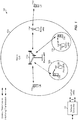
- FIG. 1 illustrates an example wireless communication network 100 including evolved Node Bs (eNBs) and user equipments (UEs), in which aspects of the present disclosure may be practiced.
- eNBs evolved Node Bs
- UEs user equipments
- UEs and eNBs may operate in a network 100 using a frame structure which supports multi-user uplink multiplexing in at least one narrowband region of a wider system bandwidth.
- a UE may identify at least one narrowband region within a wider system bandwidth, determine at least one parameter assigned to the UE for transmitting symbols of a physical uplink channel in the narrowband region that are multiplexed with symbols transmitted by one or more other UEs, and transmit the physical uplink channel using the at least one determined parameter.
- an eNB may identify at least one narrowband region within a wider system bandwidth, assign at least one parameter to a UE for transmission of symbols of a physical uplink channel in the narrowband region that are multiplexed with symbols transmitted by one or more other UEs and receive, from the UE, the physical uplink channel using the at least one assigned parameter.
- a parameter may indicate one or more of a cyclic shift, spreading code, spreading factor, a subframe hopping pattern, or a slot-based hopping pattern for UL transmissions by a UE.
- the wireless communication network 100 may be an LTE network or some other wireless network.
- Wireless communication network 100 may include a number of evolved Node Bs (eNBs) 110 and other network entities.
- An eNB is an entity that communicates with user equipments (UEs) and may also be referred to as a base station (BS), a Node B, an access point (AP), etc.
- BS base station
- AP access point
- Each eNB may provide communication coverage for a particular geographic area.
- the term "cell" can refer to a coverage area of an eNB and/or an eNB subsystem serving this coverage area, depending on the context in which the term is used.
- An eNB may provide communication coverage for a macro cell, a pico cell, a femto cell, and/or other types of cell.
- a macro cell may cover a relatively large geographic area (e.g., several kilometers in radius) and may allow unrestricted access by UEs with service subscription.
- a pico cell may cover a relatively small geographic area and may allow unrestricted access by UEs with service subscription.
- a femto cell may cover a relatively small geographic area (e.g., a home) and may allow restricted access by UEs having association with the femto cell (e.g., UEs in a closed subscriber group (CSG)).
- An eNB for a macro cell may be referred to as a macro eNB.
- An eNB for a pico cell may be referred to as a pico eNB.
- An eNB for a femto cell may be referred to as a femto eNB or a home eNB (HeNB).
- HeNB home eNB
- an eNB 110a may be a macro eNB for a macro cell 102a
- an eNB 110b may be a pico eNB for a pico cell 102b
- an eNB 110c may be a femto eNB for a femto cell 102c.
- An eNB may support one or multiple (e.g., three) cells.
- the terms "eNB,” “base station,” and “cell” may be used interchangeably herein.
- Wireless communication network 100 may also include relay stations.
- a relay station is an entity that can receive a transmission of data from an upstream station (e.g., an eNB or a UE) and send a transmission of the data to a downstream station (e.g., a UE or an eNB).
- a relay station may also be a UE that can relay transmissions for other UEs.
- a relay (station) eNB 110d may communicate with macro eNB 110a and a UE 120d in order to facilitate communication between eNB 110a and UE 120d.
- a relay station may also be referred to as a relay eNB, a relay base station, a relay, etc.
- Wireless communication network 100 may be a heterogeneous network that includes eNBs of different types, e.g., macro eNBs, pico eNBs, femto eNBs, relay eNBs, etc. These different types of eNBs may have different transmit power levels, different coverage areas, and different impact on interference in wireless communication network 100.
- macro eNBs may have a high transmit power level (e.g., 5 to 40 W) whereas pico eNBs, femto eNBs, and relay eNBs may have lower transmit power levels (e.g., 0.1 to 2 W).
- a network controller 130 may couple to a set of eNBs and may provide coordination and control for these eNBs.
- Network controller 130 may communicate with the eNBs via a backhaul.
- the eNBs may also communicate with one another, e.g., directly or indirectly via a wireless or wireline backhaul.
- UEs 120 may be dispersed throughout wireless communication network 100, and each UE may be stationary or mobile.
- a UE may also be referred to as an access terminal, a terminal, a mobile station (MS), a subscriber unit, a station (STA), etc.
- a UE may be a cellular phone, a personal digital assistant (PDA), a wireless modem, a wireless communication device, a handheld device, a laptop computer, a cordless phone, a wireless local loop (WLL) station, a tablet, a smart phone, a netbook, a smartbook, an ultrabook, etc.
- PDA personal digital assistant
- WLL wireless local loop
- One or more UEs 120 in the wireless communication network 100 may also be low cost (LC), low data rate devices, e.g., such as MTC UEs, eMTC UEs, etc.
- the UEs may co-exist with legacy and/or advanced UEs in the LTE network and may have one or more capabilities that are limited when compared to the other UEs (e.g., non-LC UEs) in the wireless network.
- the LC UEs may operate with one or more of the following: a reduction in maximum bandwidth (relative to legacy UEs), a single receive radio frequency (RF) chain, reduction of peak rate, reduction of transmit power, rank 1 transmission, half duplex operation, etc.
- Devices with limited communication resources such as MTC devices, eMTC devices, etc. may be referred to generally as LC UEs.
- legacy devices such as legacy and/or advanced UEs (e.g., in LTE) may be referred to generally as non-LC UEs.
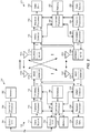
- FIG. 2 is a block diagram 200 of a design of an eNB 110 and UE 120, which may be one of the eNBs 110 and UEs 120, respectively, in FIG. 1 .
- a transmit processor 220 may receive data from a data source 212 for one or more UEs, select one or more modulation and coding schemes (MCSs) for each UE based on channel quality indicators (CQIs) received from the UE, process (e.g., encode and modulate) the data for each UE based on the MCS(s) selected for the UE, and provide data symbols for all UEs. Transmit processor 220 may also process system information (e.g., for semi-static resource partitioning information (SRPI), etc.) and control information (e.g., CQI requests, grants, upper layer signaling, etc.) and provide overhead symbols and control symbols.
- system information e.g., for semi-static resource partitioning information (SRPI), etc.
- control information e.g., CQI requests, grants, upper layer signaling, etc.
- Processor 220 may also generate reference symbols for reference signals (e.g., the common reference signal (CRS)) and synchronization signals (e.g., the primary synchronization signal (PSS) and secondary synchronization signal (SSS)).
- a transmit (TX) multiple-input multiple-output (MIMO) processor 230 may perform spatial processing (e.g., precoding) on the data symbols, the control symbols, the overhead symbols, and/or the reference symbols, if applicable, and may provide T output symbol streams to T modulators (MODs) 232a through 232t. Each MOD 232 may process a respective output symbol stream (e.g., for OFDM, etc.) to obtain an output sample stream.
- TX multiple-input multiple-output
- MIMO multiple-input multiple-output
- Each MOD 232 may process a respective output symbol stream (e.g., for OFDM, etc.) to obtain an output sample stream.
- Each MOD 232 may further process (e.g., convert to analog, amplify, filter, and upconvert) the output sample stream to obtain a downlink signal.
- T downlink signals from modulators 232a through 232t may be transmitted via T antennas 234a through 234t, respectively.
- antennas 252a through 252r may receive the downlink signals from eNB 110 and/or other eNBs and may provide received signals to demodulators (DEMODs) 254a through 254r, respectively.
- Each DEMOD 254 may condition (e.g., filter, amplify, downconvert, and digitize) its received signal to obtain input samples.
- Each DEMOD 254 may further process the input samples (e.g., for OFDM, etc.) to obtain received symbols.
- a MIMO detector 256 may obtain received symbols from all R demodulators 254a through 254r, perform MIMO detection on the received symbols if applicable, and provide detected symbols.
- a receive processor 258 may process (e.g., demodulate and decode) the detected symbols, provide decoded data for UE 120 to a data sink 260, and provide decoded control information and system information to a controller/processor 280.
- a channel processor may determine reference signal received power (RSRP), received signal strength indicator (RSSI), reference signal received quality (RSRQ), CQI, etc.
- a transmit processor 264 may receive and process data from a data source 262 and control information (e.g., for reports comprising RSRP, RSSI, RSRQ, CQI, etc.) from controller/processor 280. Processor 264 may also generate reference symbols for one or more reference signals. The symbols from transmit processor 264 may be precoded by a TX MIMO processor 266 if applicable, further processed by MODs 254a through 254r (e.g., for SC-FDM, OFDM, etc.), and transmitted to eNB 110.
- control information e.g., for reports comprising RSRP, RSSI, RSRQ, CQI, etc.
- Processor 264 may also generate reference symbols for one or more reference signals.
- the symbols from transmit processor 264 may be precoded by a TX MIMO processor 266 if applicable, further processed by MODs 254a through 254r (e.g., for SC-FDM, OFDM, etc.), and transmitted to eNB 110.
- the uplink signals from UE 120 and other UEs may be received by antennas 234, processed by DEMODs 232, detected by a MIMO detector 236 if applicable, and further processed by a receive processor 238 to obtain decoded data and control information sent by UE 120.
- Processor 238 may provide the decoded data to a data sink 239 and the decoded control information to controller/processor 240.
- eNB 110 may include communication unit 244 and communicate to network controller 130 via communication unit 244.
- Network controller 130 may include communication unit 294, controller/processor 290, and memory 292.
- Controllers/processors 240 and 280 may direct the operation at eNB 110 and UE 120, respectively.
- controller/processor 240 and/or other processors and modules at eNB 110 may perform or direct operations 700 and/or other processes for the techniques described herein.
- controller/processor 280 and/or other processors and modules at UE 120 may perform or direct operations 600 and/or processes for the techniques described herein.
- Memories 242 and 282 may store data and program codes for eNB 110 and UE 120, respectively.
- one or more of the receive processor 258, controller/processor 280, transmit processor 264, and/or memory 282 may be configured to identify at least one narrowband region within a wider system bandwidth and determine resources assigned to the UE for transmitting symbols of a physical uplink channel in the narrowband region that are multiplexed with symbols transmitted by one or more other UEs.
- One or more of the antenna 252 and MOD 254 may be configured to transmit the physical uplink channel using the identified resources.
- One or more of the transmit processor 220, TX MIMO processor 230, controller/processor 240, scheduler 246, receiver processor 238 and/or memory 242 may be configured to identify at least one narrowband region within a wider system bandwidth and assign resources to a user equipment (UE) for transmission of symbols of a physical uplink channel in the narrowband region that are multiplexed with symbols transmitted by one or more other UEs.
- One or more of the antenna 232 and DEMOD 232 may be configured to receive, from the UE, the physical uplink channel using the identified resources.
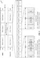
- FIG. 3 shows an exemplary frame structure 300 for FDD in LTE.
- the transmission timeline for each of the downlink and uplink may be partitioned into units of radio frames.
- Each radio frame may have a predetermined duration (e.g., 10 milliseconds (ms)) and may be partitioned into 10 subframes with indices of 0 through 9.
- Each subframe may include two slots.
- Each radio frame may thus include 20 slots with indices of 0 through 19.
- Each slot may include L symbol periods, e.g., seven symbol periods for a normal cyclic prefix (as shown in FIG. 2 ) or six symbol periods for an extended cyclic prefix.
- the 2 L symbol periods in each subframe may be assigned indices of 0 through 2 L -1.
- an eNB may transmit a primary synchronization signal (PSS) and a secondary synchronization signal (SSS) on the downlink in the center 1.08 MHz of the system bandwidth for each cell supported by the eNB.
- PSS and SSS may be transmitted in symbol periods 6 and 5, respectively, in subframes 0 and 5 of each radio frame with the normal cyclic prefix, as shown in FIG. 3 .
- the PSS and SSS may be used by UEs for cell search and acquisition.
- the eNB may transmit a cell-specific reference signal (CRS) across the system bandwidth for each cell supported by the eNB.
- the CRS may be transmitted in certain symbol periods of each subframe and may be used by the UEs to perform channel estimation, channel quality measurement, and/or other functions.
- the eNB may also transmit a physical broadcast channel (PBCH) in symbol periods 0 to 3 in slot 1 of certain radio frames.
- PBCH physical broadcast channel
- the PBCH may carry some system information.
- the eNB may transmit other system information such as system information blocks (SIBs) on a physical downlink shared channel (PDSCH) in certain subframes.
- SIBs system information blocks
- PDSCH physical downlink shared channel
- the eNB may transmit control information/data on a physical downlink control channel (PDCCH) in the first B symbol periods of a subframe, where B may be configurable for each subframe.
- the eNB may transmit traffic data and/or other data on the PDSCH in the remaining symbol periods of each subframe.
- E-UTRA Evolved Universal Terrestrial Radio Access
- FIG. 4 shows two example subframe formats 410 and 420 for the downlink with a normal cyclic prefix.
- the available time frequency resources for the downlink may be partitioned into resource blocks (RBs).
- RB resource blocks
- Each RB may cover 12 subcarriers in one slot and may include a number of resource elements.
- Each resource element may cover one subcarrier in one symbol period and may be used to send one modulation symbol, which may be a real or complex value.
- Subframe format 410 may be used for an eNB equipped with two antennas.
- a CRS may be transmitted from antennas 0 and 1 in symbol periods 0, 4, 7, and 11.
- a reference signal is a signal that is known a priori by a transmitter and a receiver and may also be referred to as pilot.
- a CRS is a reference signal that is specific for a cell, e.g., generated based on a cell identity (ID).
- ID cell identity
- Subframe format 420 may be used for an eNB equipped with four antennas.
- a CRS may be transmitted from antennas 0 and 1 in symbol periods 0, 4, 7, and 11 and from antennas 2 and 3 in symbol periods 1 and 8.
- a CRS may be transmitted on evenly spaced subcarriers, which may be determined based on cell ID. Different eNBs may transmit their CRSs on the same or different subcarriers, depending on their cell IDs.
- resource elements not used for the CRS may be used to transmit data (e.g., traffic data, control data, and/or other data).
- An interlace structure may be used for each of the downlink and uplink for FDD in LTE.
- Q interlaces with indices of 0 through Q -1 may be defined, where Q may be equal to 4, 6, 8, 10, or some other value.
- Each interlace may include subframes that are spaced apart by Q frames.
- interlace q may include subframes q, q + Q, q +2 Q, etc., where q ⁇ ⁇ 0,..., Q - 1 ⁇ .
- the wireless network may support hybrid automatic retransmission request (HARQ) for data transmission on the downlink and uplink.
- HARQ hybrid automatic retransmission request
- a transmitter e.g., an eNB 110
- a receiver e.g., a UE 120
- all transmissions of the packet may be sent in subframes of a single interlace.
- each transmission of the packet may be sent in any subframe.
- a UE may be located within the coverage of multiple eNBs. One of these eNBs may be selected to serve the UE. The serving eNB may be selected based on various criteria such as received signal strength, received signal quality, path loss, etc. Received signal quality may be quantified by a signal-to-interference-plus-noise ratio (SINR), or a reference signal received quality (RSRQ), or some other metric.
- SINR signal-to-interference-plus-noise ratio
- RSRQ reference signal received quality
- the UE may operate in a dominant interference scenario in which the UE may observe high interference from one or more interfering eNBs.
- LTE long term evolution
- DL downlink
- UL uplink
- DL and UL link budgets are designed for coverage of high end devices, such as state-of-the-art smartphones and tablets, which may support a relatively large DL and UL link budget.
- DL downlink
- UL uplink
- low cost, low rate devices need to be supported as well.
- one or more UEs in the wireless communication network may be devices that have limited communication resources, such as LC UEs, as compared to other (non-LC) devices in the wireless communication network.
- the LC UE e.g., MTC, eMTC UE
- the LC UE may be limited to a particular narrowband assignment within an available system bandwidth.
- the LC UE may be able to retune to different narrowband regions within the available system bandwidth of the LTE system, for example, in order to co-exist within the LTE system.
- LC UEs may be able to receive (with repetition) legacy physical broadcast channel (PBCH) (e.g., the LTE physical channel that, in general, carries parameters that may be used for initial access to the cell) and support one or more legacy physical random access channel (PRACH) formats.
- PBCH legacy physical broadcast channel
- PRACH legacy physical random access channel
- the LC UE may be able to receive the legacy PBCH with one or more additional repetitions of the PBCH across multiple subframes.
- the LC UE may be able to transmit one or more repetitions of PRACH (e.g., with one or more PRACH formats supported) to an eNB in the LTE system.
- the PRACH may be used to identify the LC UE.
- the number of repeated PRACH attempts may be configured by the eNB.
- the LC UE may also be a link budget limited device and may operate in different modes of operation (e.g. entailing different amounts of repeated messages transmitted to or from the LC UE) based on its link budget limitation. For example, in some cases, the LC UE may operate in a normal coverage mode in which there is little to no repetition (e.g., the amount of repetition needed for the UE to successfully receive and/or transmit a message may be low or repetition may not even be needed). Alternatively, in some cases, the LC UE may operate in a coverage enhancement (CE) mode in which there may be high amounts of repetition. For example, for a 328 bit payload, a LC UE in CE mode may need 150 or more repetitions of the payload in order to successfully receive the payload.
- CE coverage enhancement
- the LC UE may have limited capabilities with respect to its reception of broadcast and unicast transmissions.
- the maximum transport block (TB) size for a broadcast transmission received by the LC UE may be limited to 1000 bits.
- the LC UE may not be able to receive more than one unicast TB in a subframe.
- the LC UE may not be able to receive more than one broadcast TB in a subframe.
- the LC UE may not be able to receive both a unicast TB and a broadcast TB in a subframe.
- LC UEs that co-exist in the LTE system may also support new messages for certain procedures, such as paging, random access procedure, etc. (e.g., as opposed to conventional messages used in LTE for these procedures).
- new messages for paging, random access procedure, etc. may be separate from the messages used for similar procedures associated with non-LC UEs.
- LC UEs may able to monitor and/or receive paging messages that non-LC UEs may not able to monitor and/or receive.
- LC UEs may be able to receive RAR messages that also may not be able to be received by non-LC UEs.
- the new paging and RAR messages associated with LC UEs may also be repeated one or more times (e.g., "bundled").
- different numbers of repetitions e.g., different bundling sizes
- aspects of the present disclosure provide a new frame structure for eMTC UEs which advantageously supports multi-user multiplexing.
- eMTC UEs often communicate with a limited set of resources, for example, using only a narrowband region of overall system bandwidth. This narrowband region may range in size, for example, from 6 resource blocks (RBs) to a single RB or less (where each RB may cover 12 subcarriers (tones) in one slot of a subframe and may include a number of resource elements).
- RBs resource blocks
- each RB may cover 12 subcarriers (tones) in one slot of a subframe and may include a number of resource elements.
- multiplexing multiple eMTC UEs may present challenges.
- the limited resources used by these UEs also mean that there are limited resources available to share for multiplexing multiple eMTC UEs.
- CE coverage enhancements
- eMTC eMTC
- the term CE generally refers to any type of mechanism that extends the coverage range of a device (such as an eMTC device) within a network.
- One approach for CE includes bundling which refers to transmitting the same data multiple times. Transmitting the same data multiple times may refer to transmitting the same data across multiple subframes or transmitting the same data across multiple symbols within a same subframe.
- Certain systems may provide MTC UEs with coverage enhancements of up to 15 dB, which maps to 155.7 dB maximum coupling loss between the UE and an eNB. Accordingly, eMTC UEs and eNBs may perform measurements at low SNRs (e.g., -15 dB to -20 dB).
- coverage enhancements may include channel bundling, wherein messages associated with eMTC UEs may be bundled (e.g., repeated across multiple subframes or repeated across multiple symbols within a same subframe).
- eMTC UEs may support narrowband operation while operating in a wider system bandwidth. For example, an eMTC UE may transmit and receive in a narrowband region of a wider system bandwidth. As noted above, the narrowband region may span 6 RBs to a single RB or less.
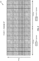
- FIG. 5 illustrates an example frame structure 500 for a physical uplink shared channel.
- a first UE may use dedicated RBs (e.g., RBs dedicated to that UE). Accordingly, other UEs may not be multiplexed in those RBs (dedicated to the first UE) for transmitting to a single eNB.
- dedicated RBs e.g., RBs dedicated to that UE. Accordingly, other UEs may not be multiplexed in those RBs (dedicated to the first UE) for transmitting to a single eNB.
- the first UE may occupy certain RBs and may not perform frequency hopping. As illustrated, the first UE may transmit reference signals (RS) using two symbols (one RS in each of the 0.5 slots) and the first UE may transmit PUSCH using the remaining symbols.
- RS reference signals
- a shortened PUSCH format may be used, for example, when a last symbol of the PUSCH frame structure 500 is used for a sounding reference signal (SRS) transmission.
- SRS sounding reference signal
- the UE may transmit RS symbols using two symbols (one RS in each of the 0.5 ms slots of the subframe of the frame 500), a SRS using one symbol of the frame 500, and PUSCH using the remaining symbols of the frame 500.
- PUSCH transmissions may be bundled for eMTC UEs.
- Bundling PUSCH transmissions means that the PUSCH transmissions may be repeated over multiple subframes and/or over multiple symbols within a same subframe.
- the bundling size which may refer to the number of repetitions, may depend on CE levels. According to aspects, more repetitions may correspond to a greater CE. Unfortunately, bundling may reduce a UE's overall capacity as resources are used by the UE for repeating messages.
- cross-subframe frequency hopping between subbands for PUSCH may be supported for an uplink channel for eMTC devices.
- Cross-subframe frequency hopping between subbands may refer to the use of different frequency resources by a UE in different subframes (e.g., different frequency resources used by the UE across subframes).
- an eMTC device may transmit symbols on the PUSCH using a first frequency in a first subframe and may subsequently hop to a different frequency to transmit symbols on the PUSCH using a second frequency in a second subframe.
- Support for cross-subframe frequency hopping may indicate how many times hopping is allowed by an eMTC UE, how long each eMTC UE may remain on a frequency, and/or support of slot-based frequency hopping for PUSCH.
- Slot-based frequency hopping may refer to a device retuning from a first frequency in a first slot of a subframe to a second frequency in a second slot of the same subframe to transmit symbols on the PUSCH.
- an eMTC UE may operate in a narrowband region within a wider system bandwidth.
- the eMTC UE may operate in a narrowband region that spans a single RB.
- a "one RB" eMTC design may present challenges for supporting multiple users. As described above, it may be difficult to share the limited frequency resources of a single RB among multiple users. In an effort to support multiple users, UEs may use a fraction of the single RB. Each UE may be assigned a single tone or a few tones of the RB, rather than each UE being assigned an entire RB. However, use of a fraction of a single RB diverges from current LTE numerology and may cause a loss in frequency diversity.
- aspects of the present disclosure provide a new frame structure for eMTC UEs which advantageously supports user multiplexing by allocating different parameters (which indicate, for example, different spreading codes, cyclic shifts, spreading factors, and/or hopping patterns) for use in uplink transmissions using shared resources.
- a UE may determine (e.g., be assigned) at least one parameter indicating one or more of a spreading code, cyclic shift, spreading factor, and/or hopping pattern to use for uplink transmission.
- the frame structure which supports multi-user multiplexing described herein may be implemented in a "one RB" eMTC design and/or a fractional RB design (e.g., wherein each UE may be assigned a fraction of an RB such as a single tone).
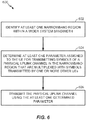
- FIG. 6 illustrates example operations 600 which may be performed by a UE, according to aspects of the present disclosure.
- UE 120a, 120b, and/or 120c in FIG. 1 which may include one or more modules of UE 120 in FIG. 2 may be configured to perform the operations described herein.
- the receive processor 258, transmit processor 264, controller/processor 280, memory 282, antenna 252 and/or demodulator/modulators 254 of the UE 120 may perform the operations described herein.
- the UE may identify at least one narrowband region within a wider system bandwidth.
- the UE may determine at least one parameter assigned to the UE for transmitting symbols of a physical uplink channel in the narrowband region that are multiplexed with symbols transmitted by one or more other UEs.
- the UE may transmit the physical uplink channel using the at least one determined parameter.
- a parameter may indicate one or more of a cyclic shift, spreading code, spreading factor (which refers to the length of a spreading code), a subframe hopping pattern, or a slot-based hopping pattern to be used by the UE for UL transmissions.
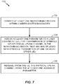
- FIG. 7 illustrates example operations 700 which may be performed by an eNB, according to aspects of the present disclosure.
- eNB 110a, 110b, 110c, and/or 110d in FIG. 1 which may include one or more modules of eNB 110 in FIG. 2 may be configured to perform the operations described herein.
- the transmit processor, 220, receive processor 238, controller/processor 240, memory 242, antenna 234 and/or demodulator/modulators 232 of the eNB 110 may perform the operations described herein.
- the eNB may identify at least one narrowband region within a wider system bandwidth. As noted above, the narrowband regions may span from one to six RBs.
- the eNB may assign at least one parameter to a UE for transmission of symbols of a physical uplink channel in the narrowband region that are multiplexed with symbols transmitted by one or more other UEs.
- the eNB may receive, from the UE, the physical uplink channel using the at least one assigned parameter.
- the resources of the narrowband region can be multiplexed among the multiple users.
- the eNB may assign different cyclic shifts (e.g., different shifted Chu sequences) or spreading codes to the UEs.
- the UE may apply the assigned cyclic shift or spreading codes to their respective transmissions.
- transmissions from different eMTC UEs using the same frequency resources may be orthogonal in the frequency domain.
- transmissions from different eMTC UEs using the same set of symbols or subframes may be orthogonal in the time domain.
- a combination of spreading codes and cyclic shifts may be used by UEs in an effort to support multiple users.
- data symbols from eMTC UEs may be multiplexed using spreading codes (orthogonal covers) over multiple symbols in the time domain.
- a configurable spreading factor SF
- the term spreading factor generally refers to the length of the spreading code.
- the spreading factor may refer to the number of times the spreading code is to be applied to a repeated transmission.
- a "1" of the spreading code may correspond to a non-inverted version of a transmission and a "-1" of the spreading code may correspond to an inverted version of the transmission.
- RS symbols from eMTC UEs may be multiplexed using spreading with orthogonal covers in the time domain, applying a cyclic shifts in frequency domain, or a combination of both spreading using orthogonal covers and applying cyclic shifts.
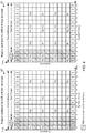
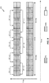
- FIG. 8 illustrates an example frame structure 800 for multi-user multiplexing, according to aspects of the present disclosure.
- the SF 1.
- each symbol will be different.
- data symbols of the frame 800 may be spread over multiple symbols, where spreading codes may be used to transmit data symbols over N adjacent symbols periods.
- a UE may multiply data symbols by a code sequence (spreading code) of length N and transmit the data symbols on a specific subcarrier for the next N OFDM symbols.
- the spreading codes used by the UEs may be configured by an eNB and known by a receiver.
- the spreading codes may be used by an eNB to receive data from multiple UEs using a same time-frequency resource. In this manner, the multi-user multiplexing described herein may increase user capacity.
- the number of devices e.g. UEs
- SF 2
- spreading codes [1,1] and [1,-1] result in orthogonal transmissions after each transmission from a different UE is multiplied with one of these codes.
- SF 2 for a group of two data symbols
- transmissions from up to two different UEs for the group of data symbols may be supported.
- SF 4 for a group of four data symbols
- orthogonal transmissions from up to four different UEs may be supported.
- a longer spreading code may support more orthogonal transmissions, wherein the orthogonal transmissions may be from different users.
- a longer spreading code e.g., associated with a larger spreading factor
- cyclic shifts may be used for separation per reference signal symbol in the frequency domain.
- a 2x2, 3x2, or 6x2 combination of time and frequency multiplexing may be used for reference signal symbols.
- the first set of four data symbols 808a may use a first set of frequency resources and the second set of four data symbols 808b may use a second set of frequency resources.
- the set of four data symbols 808b may span the first and second slot of the subframe 800.
- FIG. 9 illustrates an example subframe format 900, which supports uplink multi-user multiplexing, in accordance with aspects of the present disclosure.
- the SF format 900 may support orthogonal transmission by three users, using three different spreading codes that result in orthogonal transmissions.
- the SF may support 11 users.
- a retuning time for a UE to tune from one frequency to another for cross-slot or cross-subframe multiplexing may not destroy orthogonality between the multiplexed UEs.
- a SF 2 or 3 may be supported.
- the first symbols (e.g., 2 or 3 symbols) in a first slot of a next subframe may be dropped (e.g., not used for UL transmission).
- the last symbols e.g., 2 or 3 symbols
- the last slot of the current subframe e.g., assuming the UE hops from a current subframe to a next subframe
- may be dropped e.g., not be used for UL transmission by the UE
- retuning for cross-subframe frequency hopping may occur during a last one or more symbols of the first subframe, a first one or more symbols of the second subframe, or a combination of symbols from the first and second subframe. In this manner, retuning for cross-subframe frequency hopping may occur during at least one of a last one or more symbols of the first subframe or a first one or more symbols of the second subframe.
- a SF 2 or 3 may be used.
- the first symbols (e.g., 2 or 3 symbols) of the second slot of a next subframe or the last symbols (e.g., 2 or 3 symbols) in the first slot of the subframe may be dropped.
- Multi-user multiplexing on an uplink channel may advantageously increase user capacity. This may be especially important in the 1 RB eMTC design which, as described above, has limited dimensions. Furthermore, the increased user capacity using 1 RB may provide an alternative design to a fractional RB design and may remain consistent with LTE numerology. Additionally, a flexible SF may be used for balancing user capacity and data rates for the multiple UEs.
- a SF may be greater than 1, which may support more than one user.
- the eNB may only schedule a single user even though the SF is greater than 1.
- the SF may be 2 and the eNB may only schedule a single UE.
- the eNB may use the repetition of the received data symbols from the single UE in an effort to improve the tracking loop.
- the eNB may cross-correlate the repeated, spread symbols to estimate the frequency offset.
- aspects of the present disclosure may provide better orthogonality due to, for example, a shorter spreading period across symbols (as opposed to across subframes).
- the spreading period may be shorter (e.g., 2 symbols) using aspects described herein.
- a shorter spreading period may allow for better orthogonalities as compared to spreading across subframes.
- the channel may need to remain the same within the spreading period and groups of users may need to hop at a same time, in an effort to maintain orthogonalities.
- spreading within a subframe may allow users to hop frequencies independently.
- aspects of the present disclosure may not reduce a data rate or transport block (TB) size because spreading may be considered to reshuffle data symbols across multiple subframes.
- the TB size determination may take into account SF and bundling and may be easily scaled. Therefore, a user capacity may increase without reduction of a data rate.
- a phrase referring to "at least one of' a list of items refers to any combination of those items, including single members.
- "at least one of: a, b, or c” is intended to cover: a, b, c, a-b, a-c, b-c, and a-b-c.
- a software/firmware module may reside in RAM memory, flash memory, ROM memory, EPROM memory, EEPROM memory, PCM (phase change memory), registers, hard disk, a removable disk, a CD-ROM or any other form of storage medium known in the art.
- An exemplary storage medium is coupled to the processor such that the processor can read information from, and/or write information to, the storage medium.
- the storage medium may be integral to the processor.
- the processor and the storage medium may reside in an ASIC.
- the ASIC may reside in a user terminal.
- the processor and the storage medium may reside as discrete components in a user terminal.
- one or more components of the UE and/or eNB may perform the means described and recited herein.
- one or more of the receive processor 258, controller/processor 280, transmit processor 264, and/or memory 282 may be configured to identify at least one narrowband region within a wider system bandwidth and determine resources assigned to the UE for transmitting symbols of a physical uplink channel in the narrowband region that are multiplexed with symbols transmitted by one or more other UEs.
- One or more of the antenna 252 and MOD 254 may be configured to transmit the physical uplink channel using the identified resources.
- One or more of the transmit processor 220, TX MIMO processor 230, controller/processor 240, scheduler 246, receiver processor 238 and/or memory 242 may be configured to identify at least one narrowband region within a wider system bandwidth and assign resources to a user equipment (UE) for transmission of symbols of a physical uplink channel in the narrowband region that are multiplexed with symbols transmitted by one or more other UEs.
- One or more of the antenna 232 and DEMOD 232 may be configured to receive, from the UE, the physical uplink channel using the identified resources.
- the functions described may be implemented in hardware, software/firmware or combinations thereof. If implemented in software/firmware, the functions may be stored on or transmitted over as one or more instructions or code on a computer-readable medium.
- Computer-readable media includes both computer storage media and communication media including any medium that facilitates transfer of a computer program from one place to another.
- a storage media may be any available media that can be accessed by a general purpose or special purpose computer.
- such computer-readable media can comprise RAM, ROM, EEPROM, CD-ROM or other optical disk storage, magnetic disk storage or other magnetic storage devices, or any other medium that can be used to carry or store desired program code means in the form of instructions or data structures and that can be accessed by a general-purpose or special-purpose computer, or a general-purpose or special-purpose processor. Also, any connection is properly termed a computer-readable medium.
- Disk and disc includes compact disc (CD), laser disc, optical disc, digital versatile disc (DVD), floppy disk and Blu-ray disc where disks usually reproduce data magnetically, while discs reproduce data optically with lasers. Combinations of the above should also be included within the scope of computer-readable media.
Landscapes
- Engineering & Computer Science (AREA)
- Signal Processing (AREA)
- Computer Networks & Wireless Communication (AREA)
- Databases & Information Systems (AREA)
- Mobile Radio Communication Systems (AREA)
Claims (15)
- Un procédé destiné à des communications sans fil par un équipement d'utilisateur (120), UE, comprenant :l'identification (602) d'au moins une zone à bande étroite à l'intérieur d'une bande passante système plus large,la détermination (604) d'au moins un paramètre affecté à l'UE pour la transmission de symboles d'un canal en liaison montante physique dans la zone à bande étroite qui sont multiplexés avec des symboles transmis par un ou plusieurs autres UE, où le au moins un paramètre comprend au moins un élément parmi un décalage cyclique, un paramètre d'étalement ou un modèle de saut, etla transmission (606), à un nœud B évolué (110), eNB, des symboles du canal en liaison montante physique au moyen du au moins un paramètre déterminé, où les symboles du canal en liaison montante physique sont répétés sur une pluralité de symboles à l'intérieur d'une même sous-trame et multiplexés au moyen de codes d'étalement sur la pluralité de symboles dans un domaine temporel, où les symboles sont transmis au moyen de ressources temps-fréquence utilisées par les un ou plusieurs autres UE,où l'UE et les un ou plusieurs autres UE fonctionnent dans une zone à bande étroite qui couvre un bloc de ressource unique, RB, et où à chaque UE parmi l'UE et les un ou plusieurs autres UE est affecté au moins une tonalité du RB unique, où un RB comprend une pluralité de tonalités et une période d'intervalle de temps dans le domaine temporel, une sous-trame comprend deux intervalles de temps consécutifs et chaque intervalle de temps comprend L symboles OFDM.
- Le procédé selon la Revendication 1, où :le au moins un paramètre comprend le décalage cyclique, etla transmission du canal en liaison montante physique comprend l'application du décalage cyclique de façon à transmettre des signaux de référence, RS, dans un ou plusieurs symboles du canal en liaison montante physique.
- Le procédé selon la Revendication 1, où :le au moins un paramètre comprend le paramètre d'étalement et le paramètre d'étalement comprend un code d'étalement, etla transmission du canal en liaison montante physique comprend l'application du code d'étalement de façon à transmettre des signaux de référence, RS, ou des symboles de données dans une pluralité de symboles du canal en liaison montante physique.
- Le procédé selon la Revendication 1, où :le au moins un paramètre comprend le paramètre d'étalement et le paramètre d'étalement comprend un facteur d'étalement, SF, configurable basé, au moins en partie, sur un format d'une sous-trame du canal en liaison montante physique, une taille de regroupement ou un niveau d'amélioration de couverture, CE, etla transmission du canal en liaison montante physique comprend l'application du SF de façon à transmettre une pluralité de symboles du canal en liaison montante physique.
- Le procédé selon la Revendication 1, où :le modèle de saut comprend un modèle de saut de sous-trame,la détermination comprend l'identification du modèle de saut de sous-trame, etla transmission du canal en liaison montante physique comprend l'application d'un facteur d'étalement de façon à transmettre le canal en liaison montante physique au moyen d'une première fréquence dans une première sous-trame et ensuite au moyen d'une deuxième fréquence dans une deuxième sous-trame à l'intérieur de la zone à bande étroite, les première et deuxième fréquences étant déterminées en fonction du modèle de saut.
- Le procédé selon la Revendication 1, où :le modèle de saut comprend un modèle de saut basé sur un intervalle de temps,la détermination comprend l'identification du modèle de saut basé sur un intervalle de temps, etla transmission du canal en liaison montante physique comprend l'application d'un facteur d'étalement de façon à transmettre le canal en liaison montante physique sur une première fréquence dans un premier intervalle de temps d'une sous-trame et ensuite sur une deuxième fréquence dans un deuxième intervalle de temps de la sous-trame à l'intérieur de la zone à bande étroite, les première et deuxième fréquences étant déterminées en fonction du modèle de saut.
- Le procédé selon les Revendications 5 ou 6, où le facteur d'étalement est basé, au moins en partie, sur un temps de reréglage de la première fréquence vers la deuxième fréquence à l'intérieur de la sous-trame.
- Le procédé selon la Revendication 1, où la transmission du canal en liaison montante physique comprend l'application d'un code d'étalement de façon à transmettre un élément parmi : des signaux de référence, RS, ou des symboles de données dans une pluralité de symboles d'une sous-trame du canal en liaison montante physique ou sur une pluralité de sous-trames du canal en liaison montante physique.
- Un procédé destiné à des communications sans fil par un nœud B évolué (110), eNB, comprenant :l'identification (702) d'au moins une zone à bande étroite à l'intérieur d'une bande passante système plus large,l'affectation (704) d'au moins un paramètre à un équipement d'utilisateur pour une transmission de symboles d'un canal en liaison montante physique dans la zone à bande étroite qui sont multiplexés avec des symboles transmis par un ou plusieurs autres UE, où le au moins un paramètre comprend au moins un élément parmi un décalage cyclique, un paramètre d'étalement ou un modèle de saut, etla réception (706), à partir de l'UE, des symboles du canal en liaison montante physique au moyen du au moins un paramètre affecté, où les symboles du canal en liaison montante physique sont répétés sur une pluralité de symboles à l'intérieur d'une même sous-trame et multiplexés au moyen de codes d'étalement sur la pluralité de symboles dans un domaine temporel, où les symboles sont reçus au moyen des ressources temps-fréquence utilisées par les un ou plusieurs autres UE,où l'UE et les un ou plusieurs autres UE fonctionnent dans une zone à bande étroite qui couvre un bloc de ressource unique, RB, et où à chaque UE parmi l'UE et les un ou plusieurs autres UE est affecté au moins une tonalité du RB unique, où un RB comprend une pluralité de tonalités et une période d'intervalle de temps dans le domaine temporel, une sous-trame comprend deux intervalles de temps consécutifs et chaque intervalle de temps comprend L symboles OFDM.
- Le procédé selon la Revendication 9, où :le au moins un paramètre comprend le décalage cyclique, etla réception du canal en liaison montante physique comprend la réception de signaux de référence, RS, avec le décalage cyclique appliqué dans un ou plusieurs symboles du canal en liaison montante physique.
- Le procédé selon la Revendication 9, où :le au moins un paramètre comprend le paramètre d'étalement et le paramètre d'étalement comprend un code d'étalement, etla réception du canal en liaison montante physique comprend la réception de signaux de référence, RS, ou de symboles de données avec le code d'étalement appliqué dans une pluralité de symboles du canal en liaison montante physique.
- Le procédé selon la Revendication 9, où :le au moins un paramètre comprend le paramètre d'étalement et le paramètre d'étalement contient un facteur d'étalement, SF, configurable basé, au moins en partie, sur un format d'une sous-trame du canal en liaison montante physique, une taille de regroupement ou un niveau d'amélioration de couverture, CE, etla réception du canal en liaison montante physique comprend la réception d'une pluralité de symboles du canal en liaison montante physique avec le SF appliqué.
- Le procédé selon la Revendication 9, où :le modèle de saut comprend un modèle de saut de sous-trame ou un modèle de saut basé sur un intervalle de temps,l'affectation du au moins un paramètre comprend l'affectation du modèle de saut de sous-trame ou du modèle de saut basé sur un intervalle de temps, etla réception du canal en liaison montante physique comprend la réception du canal en liaison montante physique avec un facteur d'étalement, SF, appliqué sur une première fréquence dans une première sous-trame et ensuite sur une deuxième fréquence dans une deuxième sous-trame à l'intérieur de la zone à bande étroite, les première et deuxième fréquences étant déterminées en fonction du modèle de saut.
- Un appareil destiné à des communications sans fil par un équipement d'utilisateur (120), UE, comprenant :un moyen d'identification d'au moins une zone à bande étroite à l'intérieur d'une bande passante système plus large,un moyen de détermination d'au moins un paramètre affecté à l'UE pour la transmission de symboles d'un canal en liaison montante physique dans la zone à bande étroite qui sont multiplexés avec des symboles transmis par un ou plusieurs autres UE, où le au moins un paramètre comprend au moins un élément parmi un décalage cyclique, un paramètre d'étalement ou un modèle de saut, etun moyen de transmission de symboles du canal en liaison montante physique au moyen du au moins un paramètre déterminé, où les symboles du canal en liaison montante physique sont répétés sur une pluralité de symboles à l'intérieur d'une même sous-trame et multiplexés au moyen de codes d'étalement sur la pluralité de symboles dans un domaine temporel, où les symboles sont transmis au moyen de ressources temps-fréquence utilisées par les un ou plusieurs autres UE,où l'UE et les un ou plusieurs autres UE fonctionnent dans une zone à bande étroite qui couvre un bloc de ressource unique, RB, et où à chaque UE parmi l'UE et les un ou plusieurs autres UE est affecté au moins une tonalité du RB unique, où un RB comprend une pluralité de tonalités et une période d'intervalle de temps dans le domaine temporel, une sous-trame comprend deux intervalles de temps consécutifs et chaque intervalle de temps comprend L symboles OFDM.
- Un appareil destiné à des communications sans fil par un nœud B évolué (110), eNB, comprenant :un moyen d'identification d'au moins une zone à bande étroite à l'intérieur d'une bande passante système plus large,un moyen d'affectation d'au moins un paramètre à un équipement d'utilisateur pour une transmission de symboles d'un canal en liaison montante physique dans la zone à bande étroite qui sont multiplexés avec des symboles transmis par un ou plusieurs autres UE, où le au moins un paramètre comprend au moins un élément parmi un décalage cyclique, un paramètre d'étalement ou un modèle de saut, etun moyen de réception, à partir de l'UE, des symboles du canal en liaison montante physique au moyen du au moins un paramètre affecté, où les symboles du canal en liaison montante physique sont répétés sur une pluralité de symboles à l'intérieur d'une même sous-trame et multiplexés au moyen de codes d'étalement sur la pluralité de symboles dans un domaine temporel, où les symboles sont reçus au moyen de ressources temps-fréquence utilisées par les un ou plusieurs autres UE,où l'UE et les un ou plusieurs autres UE fonctionnent dans une zone à bande étroite qui couvre un bloc de ressource unique, RB, et où à chaque UE parmi l'UE et les un ou plusieurs autres UE est affecté au moins une tonalité du RB unique, où un RB comprend une pluralité de tonalités et une période d'intervalle de temps dans le domaine temporel, une sous-trame comprend deux intervalles de temps consécutifs et chaque intervalle de temps comprend L symboles OFDM.
Applications Claiming Priority (3)
| Application Number | Priority Date | Filing Date | Title |
|---|---|---|---|
| US201562190248P | 2015-07-08 | 2015-07-08 | |
| US15/202,023 US10652760B2 (en) | 2015-07-08 | 2016-07-05 | Multi-user multiplexing frame structure for eMTC |
| PCT/US2016/041039 WO2017007789A1 (fr) | 2015-07-08 | 2016-07-06 | Structure de trame de multiplexage multiutilisateur pour emtc |
Publications (2)
| Publication Number | Publication Date |
|---|---|
| EP3320632A1 EP3320632A1 (fr) | 2018-05-16 |
| EP3320632B1 true EP3320632B1 (fr) | 2020-06-03 |
Family
ID=56561453
Family Applications (1)
| Application Number | Title | Priority Date | Filing Date |
|---|---|---|---|
| EP16745919.7A Active EP3320632B1 (fr) | 2015-07-08 | 2016-07-06 | Structure de trame de multiplexage multiutilisateur pour emtc |
Country Status (7)
| Country | Link |
|---|---|
| US (1) | US10652760B2 (fr) |
| EP (1) | EP3320632B1 (fr) |
| JP (1) | JP2018526867A (fr) |
| KR (1) | KR20180028437A (fr) |
| CN (1) | CN107820688B (fr) |
| BR (1) | BR112018000403A2 (fr) |
| WO (1) | WO2017007789A1 (fr) |
Families Citing this family (9)
| Publication number | Priority date | Publication date | Assignee | Title |
|---|---|---|---|---|
| FR3046328B1 (fr) * | 2015-12-28 | 2018-10-12 | Sigfox | Procede d’emission d’un message apres ecoute d’un canal de communication partage par des terminaux |
| JP6651650B2 (ja) * | 2016-04-01 | 2020-02-19 | 華為技術有限公司Huawei Technologies Co.,Ltd. | Srs切り替え、送信及び拡張のためのシステム及び方法 |
| US10448380B2 (en) * | 2016-06-27 | 2019-10-15 | Qualcomm Incorporated | Split symbol control for aligned numerology |
| JP2019149591A (ja) * | 2016-07-14 | 2019-09-05 | シャープ株式会社 | 端末装置、基地局装置、通信方法、および、集積回路 |
| CN107734683B (zh) * | 2016-08-12 | 2021-02-12 | 中兴通讯股份有限公司 | 一种信息传输方法、电子设备及计算机可读存储介质 |
| ES2940268T3 (es) * | 2016-08-24 | 2023-05-04 | Ericsson Telefon Ab L M | Métodos para señalización eficiente en comunicaciones V2X |
| KR20190103291A (ko) * | 2017-01-17 | 2019-09-04 | 광동 오포 모바일 텔레커뮤니케이션즈 코포레이션 리미티드 | 사운딩 참조 신호 전송 방법, 단말 기기 및 네트워크 기기 |
| GB201800491D0 (en) * | 2018-01-11 | 2018-02-28 | Nordic Semiconductor Asa | Radio communication |
| CN110662199B (zh) * | 2018-06-29 | 2023-03-28 | 中国电信股份有限公司 | 室内无线信号探测方法、系统和无线信号探测设备 |
Family Cites Families (24)
| Publication number | Priority date | Publication date | Assignee | Title |
|---|---|---|---|---|
| EP1909523A1 (fr) * | 2006-10-02 | 2008-04-09 | Matsushita Electric Industrial Co., Ltd. | Acquisition améliorée d'informations de système d'une autre cellule |
| US9281917B2 (en) * | 2007-01-03 | 2016-03-08 | Nokia Technologies Oy | Shared control channel structure |
| US8036166B2 (en) * | 2007-06-18 | 2011-10-11 | Nokia Corporation | Signaling of implicit ACK/NACK resources |
| US8180009B2 (en) * | 2007-11-05 | 2012-05-15 | Apple Inc. | Techniques for signaling reference signal parameters in a wireless communication system |
| US8149767B2 (en) * | 2008-03-13 | 2012-04-03 | Samsung Electronics Co., Ltd. | Methods of assigning resources for the uplink control channel in LTE |
| US8160018B2 (en) * | 2008-03-14 | 2012-04-17 | Samsung Electronics Co., Ltd. | Methods of uplink channelization in LTE |
| KR101021803B1 (ko) * | 2008-06-23 | 2011-03-22 | 가부시키가이샤 엔티티 도코모 | 기지국장치와 유저장치 및 통신제어방법 |
| US8619544B2 (en) * | 2008-09-23 | 2013-12-31 | Qualcomm Incorporated | Apparatus and method for facilitating transmit diversity for communications |
| US8705339B2 (en) * | 2009-05-29 | 2014-04-22 | Panasonic Corporation | Wireless communication apparatus and frequency hopping method |
| JP5180163B2 (ja) * | 2009-08-05 | 2013-04-10 | 株式会社エヌ・ティ・ティ・ドコモ | 移動端末装置、無線基地局装置及び無線通信方法 |
| US8619687B2 (en) * | 2010-02-12 | 2013-12-31 | Sharp Laboratories Of America, Inc. | Coordinating uplink resource allocation |
| US8750143B2 (en) * | 2010-04-02 | 2014-06-10 | Sharp Laboratories Of America, Inc. | Extended uplink control information (UCI) reporting via the physical uplink control channel (PUCCH) |
| CN103026650B (zh) * | 2010-07-26 | 2016-06-08 | Lg电子株式会社 | 在无线通信系统中发送扩展上行链路控制信息的方法和设备 |
| WO2012023819A2 (fr) * | 2010-08-18 | 2012-02-23 | 엘지전자 주식회사 | Procédé et appareil de transmission de données de liaison montante dans un système d'accès sans fil |
| GB2488512B (en) * | 2011-01-28 | 2015-03-11 | Sca Ipla Holdings Inc | Telecommunications method and system |
| EP2761955B1 (fr) * | 2011-09-30 | 2017-07-26 | Interdigital Patent Holdings, Inc. | Communication entre dispositifs à l'aide d'une largeur de bande de canal réduite |
| EP2769590B1 (fr) | 2011-10-20 | 2018-08-15 | Nokia Solutions and Networks Oy | Attribution de créneau temporel sur la liaison montante dans un système cdma |
| US9485758B2 (en) * | 2012-03-16 | 2016-11-01 | Lg Electronics Inc. | Method and apparatus for uplink transmission |
| US9408014B2 (en) * | 2012-04-24 | 2016-08-02 | Electronics And Telecommunications Research Institute | Data transmission method for machine type communication (MTC) and MTC apparatus |
| US9936523B2 (en) * | 2013-01-16 | 2018-04-03 | Telefonaktiebolaget Lm Ericsson (Publ) | PRACH signals with different bandwidths |
| US9420584B2 (en) * | 2014-09-17 | 2016-08-16 | Telefonaktiebolaget Lm Ericsson (Publ) | Uplink sounding reference signals for machine type communications (MTC) user equipment (UE) |
| US20160127936A1 (en) * | 2014-11-05 | 2016-05-05 | Debdeep CHATTERJEE | User equipment and methods for csi measurements with reduced bandwidth support |
| US9913263B2 (en) * | 2014-12-23 | 2018-03-06 | Intel Corporation | Association request for narrowband communications in a telecommunication environment |
| US9877278B2 (en) * | 2015-04-10 | 2018-01-23 | Futurewei Technologies, Inc. | Monitoring a narrowband control channel for a wideband system to reduce power consumption |
-
2016
- 2016-07-05 US US15/202,023 patent/US10652760B2/en active Active
- 2016-07-06 BR BR112018000403-0A patent/BR112018000403A2/pt not_active IP Right Cessation
- 2016-07-06 KR KR1020187000342A patent/KR20180028437A/ko not_active Application Discontinuation
- 2016-07-06 CN CN201680039646.8A patent/CN107820688B/zh active Active
- 2016-07-06 EP EP16745919.7A patent/EP3320632B1/fr active Active
- 2016-07-06 WO PCT/US2016/041039 patent/WO2017007789A1/fr active Application Filing
- 2016-07-06 JP JP2018500568A patent/JP2018526867A/ja not_active Ceased
Non-Patent Citations (1)
| Title |
|---|
| None * |
Also Published As
| Publication number | Publication date |
|---|---|
| US10652760B2 (en) | 2020-05-12 |
| US20170013481A1 (en) | 2017-01-12 |
| WO2017007789A1 (fr) | 2017-01-12 |
| JP2018526867A (ja) | 2018-09-13 |
| CN107820688A (zh) | 2018-03-20 |
| CN107820688B (zh) | 2020-12-08 |
| BR112018000403A2 (pt) | 2018-09-11 |
| EP3320632A1 (fr) | 2018-05-16 |
| KR20180028437A (ko) | 2018-03-16 |
Similar Documents
| Publication | Publication Date | Title |
|---|---|---|
| EP3320643B1 (fr) | Configuration d'une communication de type machine (mtc), gestion d'interférences et réajustement temporel pour des transmissions en liaison montante | |
| US11924810B2 (en) | Narrowband management for machine type communications | |
| US10764908B2 (en) | Subframe availability for machine type communications (MTC) | |
| CN107534835B (zh) | 基于控制信道的广播消息接发 | |
| EP3248400B1 (fr) | Conception de diversité spatiale et fréquentielle pour des communications de type machine (mtc) | |
| EP3320632B1 (fr) | Structure de trame de multiplexage multiutilisateur pour emtc | |
| US10455624B2 (en) | Ordered physical random access channel resource management | |
| EP3295597B1 (fr) | Configuration de canal physique de commande en liaison montante (pucch) pour des communications de type machine (mtc) | |
| CN113747402A (zh) | 用于共享射频频谱操作的演进型机器类型通信设计 | |
| KR20130031934A (ko) | 기준 신호 패턴들 | |
| EP2946625A1 (fr) | Attribution de ressources de canal partagé de liaison descendante physique (pdsch) à base d'élément de canal de commande amélioré (ecce) pour évolution à long terme (lte) | |
| CN113453198A (zh) | 用于增强型机器类型通信的窄带定义 | |
| WO2018128702A2 (fr) | Conception d'espace de recherche pour planification semi-persistante (sps) dans des communications de type machine améliorées | |
| KR102707716B1 (ko) | 머신 타입 통신들을 위한 협대역 관리 |
Legal Events
| Date | Code | Title | Description |
|---|---|---|---|
| STAA | Information on the status of an ep patent application or granted ep patent |
Free format text: STATUS: THE INTERNATIONAL PUBLICATION HAS BEEN MADE |
|
| PUAI | Public reference made under article 153(3) epc to a published international application that has entered the european phase |
Free format text: ORIGINAL CODE: 0009012 |
|
| STAA | Information on the status of an ep patent application or granted ep patent |
Free format text: STATUS: REQUEST FOR EXAMINATION WAS MADE |
|
| 17P | Request for examination filed |
Effective date: 20171116 |
|
| AK | Designated contracting states |
Kind code of ref document: A1 Designated state(s): AL AT BE BG CH CY CZ DE DK EE ES FI FR GB GR HR HU IE IS IT LI LT LU LV MC MK MT NL NO PL PT RO RS SE SI SK SM TR |
|
| AX | Request for extension of the european patent |
Extension state: BA ME |
|
| DAV | Request for validation of the european patent (deleted) | ||
| DAX | Request for extension of the european patent (deleted) | ||
| STAA | Information on the status of an ep patent application or granted ep patent |
Free format text: STATUS: EXAMINATION IS IN PROGRESS |
|
| 17Q | First examination report despatched |
Effective date: 20181127 |
|
| RIC1 | Information provided on ipc code assigned before grant |
Ipc: H04J 13/00 20110101AFI20190930BHEP Ipc: H04B 1/713 20110101ALI20190930BHEP Ipc: H04W 4/00 20180101ALI20190930BHEP Ipc: H04J 11/00 20060101ALI20190930BHEP Ipc: H04B 3/36 20060101ALI20190930BHEP |
|
| GRAP | Despatch of communication of intention to grant a patent |
Free format text: ORIGINAL CODE: EPIDOSNIGR1 |
|
| STAA | Information on the status of an ep patent application or granted ep patent |
Free format text: STATUS: GRANT OF PATENT IS INTENDED |
|
| INTG | Intention to grant announced |
Effective date: 20191213 |
|
| RIN1 | Information on inventor provided before grant (corrected) |
Inventor name: XU, HAO Inventor name: WANG, RENQIU Inventor name: CHEN, WANSHI |
|
| GRAS | Grant fee paid |
Free format text: ORIGINAL CODE: EPIDOSNIGR3 |
|
| GRAA | (expected) grant |
Free format text: ORIGINAL CODE: 0009210 |
|
| STAA | Information on the status of an ep patent application or granted ep patent |
Free format text: STATUS: THE PATENT HAS BEEN GRANTED |
|
| AK | Designated contracting states |
Kind code of ref document: B1 Designated state(s): AL AT BE BG CH CY CZ DE DK EE ES FI FR GB GR HR HU IE IS IT LI LT LU LV MC MK MT NL NO PL PT RO RS SE SI SK SM TR |
|
| REG | Reference to a national code |
Ref country code: GB Ref legal event code: FG4D |
|
| REG | Reference to a national code |
Ref country code: CH Ref legal event code: EP Ref country code: AT Ref legal event code: REF Ref document number: 1278142 Country of ref document: AT Kind code of ref document: T Effective date: 20200615 |
|
| REG | Reference to a national code |
Ref country code: DE Ref legal event code: R096 Ref document number: 602016037516 Country of ref document: DE |
|
| REG | Reference to a national code |
Ref country code: LT Ref legal event code: MG4D |
|
| PG25 | Lapsed in a contracting state [announced via postgrant information from national office to epo] |
Ref country code: LT Free format text: LAPSE BECAUSE OF FAILURE TO SUBMIT A TRANSLATION OF THE DESCRIPTION OR TO PAY THE FEE WITHIN THE PRESCRIBED TIME-LIMIT Effective date: 20200603 Ref country code: NO Free format text: LAPSE BECAUSE OF FAILURE TO SUBMIT A TRANSLATION OF THE DESCRIPTION OR TO PAY THE FEE WITHIN THE PRESCRIBED TIME-LIMIT Effective date: 20200903 Ref country code: GR Free format text: LAPSE BECAUSE OF FAILURE TO SUBMIT A TRANSLATION OF THE DESCRIPTION OR TO PAY THE FEE WITHIN THE PRESCRIBED TIME-LIMIT Effective date: 20200904 Ref country code: SE Free format text: LAPSE BECAUSE OF FAILURE TO SUBMIT A TRANSLATION OF THE DESCRIPTION OR TO PAY THE FEE WITHIN THE PRESCRIBED TIME-LIMIT Effective date: 20200603 Ref country code: FI Free format text: LAPSE BECAUSE OF FAILURE TO SUBMIT A TRANSLATION OF THE DESCRIPTION OR TO PAY THE FEE WITHIN THE PRESCRIBED TIME-LIMIT Effective date: 20200603 |
|
| REG | Reference to a national code |
Ref country code: NL Ref legal event code: MP Effective date: 20200603 |
|
| PG25 | Lapsed in a contracting state [announced via postgrant information from national office to epo] |
Ref country code: HR Free format text: LAPSE BECAUSE OF FAILURE TO SUBMIT A TRANSLATION OF THE DESCRIPTION OR TO PAY THE FEE WITHIN THE PRESCRIBED TIME-LIMIT Effective date: 20200603 Ref country code: RS Free format text: LAPSE BECAUSE OF FAILURE TO SUBMIT A TRANSLATION OF THE DESCRIPTION OR TO PAY THE FEE WITHIN THE PRESCRIBED TIME-LIMIT Effective date: 20200603 Ref country code: LV Free format text: LAPSE BECAUSE OF FAILURE TO SUBMIT A TRANSLATION OF THE DESCRIPTION OR TO PAY THE FEE WITHIN THE PRESCRIBED TIME-LIMIT Effective date: 20200603 Ref country code: BG Free format text: LAPSE BECAUSE OF FAILURE TO SUBMIT A TRANSLATION OF THE DESCRIPTION OR TO PAY THE FEE WITHIN THE PRESCRIBED TIME-LIMIT Effective date: 20200903 |
|
| REG | Reference to a national code |
Ref country code: AT Ref legal event code: MK05 Ref document number: 1278142 Country of ref document: AT Kind code of ref document: T Effective date: 20200603 |
|
| PG25 | Lapsed in a contracting state [announced via postgrant information from national office to epo] |
Ref country code: AL Free format text: LAPSE BECAUSE OF FAILURE TO SUBMIT A TRANSLATION OF THE DESCRIPTION OR TO PAY THE FEE WITHIN THE PRESCRIBED TIME-LIMIT Effective date: 20200603 Ref country code: NL Free format text: LAPSE BECAUSE OF FAILURE TO SUBMIT A TRANSLATION OF THE DESCRIPTION OR TO PAY THE FEE WITHIN THE PRESCRIBED TIME-LIMIT Effective date: 20200603 |
|
| PG25 | Lapsed in a contracting state [announced via postgrant information from national office to epo] |
Ref country code: EE Free format text: LAPSE BECAUSE OF FAILURE TO SUBMIT A TRANSLATION OF THE DESCRIPTION OR TO PAY THE FEE WITHIN THE PRESCRIBED TIME-LIMIT Effective date: 20200603 Ref country code: SM Free format text: LAPSE BECAUSE OF FAILURE TO SUBMIT A TRANSLATION OF THE DESCRIPTION OR TO PAY THE FEE WITHIN THE PRESCRIBED TIME-LIMIT Effective date: 20200603 Ref country code: RO Free format text: LAPSE BECAUSE OF FAILURE TO SUBMIT A TRANSLATION OF THE DESCRIPTION OR TO PAY THE FEE WITHIN THE PRESCRIBED TIME-LIMIT Effective date: 20200603 Ref country code: CZ Free format text: LAPSE BECAUSE OF FAILURE TO SUBMIT A TRANSLATION OF THE DESCRIPTION OR TO PAY THE FEE WITHIN THE PRESCRIBED TIME-LIMIT Effective date: 20200603 Ref country code: ES Free format text: LAPSE BECAUSE OF FAILURE TO SUBMIT A TRANSLATION OF THE DESCRIPTION OR TO PAY THE FEE WITHIN THE PRESCRIBED TIME-LIMIT Effective date: 20200603 Ref country code: PT Free format text: LAPSE BECAUSE OF FAILURE TO SUBMIT A TRANSLATION OF THE DESCRIPTION OR TO PAY THE FEE WITHIN THE PRESCRIBED TIME-LIMIT Effective date: 20201006 Ref country code: AT Free format text: LAPSE BECAUSE OF FAILURE TO SUBMIT A TRANSLATION OF THE DESCRIPTION OR TO PAY THE FEE WITHIN THE PRESCRIBED TIME-LIMIT Effective date: 20200603 Ref country code: IT Free format text: LAPSE BECAUSE OF FAILURE TO SUBMIT A TRANSLATION OF THE DESCRIPTION OR TO PAY THE FEE WITHIN THE PRESCRIBED TIME-LIMIT Effective date: 20200603 |
|
| PG25 | Lapsed in a contracting state [announced via postgrant information from national office to epo] |
Ref country code: SK Free format text: LAPSE BECAUSE OF FAILURE TO SUBMIT A TRANSLATION OF THE DESCRIPTION OR TO PAY THE FEE WITHIN THE PRESCRIBED TIME-LIMIT Effective date: 20200603 Ref country code: PL Free format text: LAPSE BECAUSE OF FAILURE TO SUBMIT A TRANSLATION OF THE DESCRIPTION OR TO PAY THE FEE WITHIN THE PRESCRIBED TIME-LIMIT Effective date: 20200603 Ref country code: IS Free format text: LAPSE BECAUSE OF FAILURE TO SUBMIT A TRANSLATION OF THE DESCRIPTION OR TO PAY THE FEE WITHIN THE PRESCRIBED TIME-LIMIT Effective date: 20201003 |
|
| REG | Reference to a national code |
Ref country code: CH Ref legal event code: PL |
|
| REG | Reference to a national code |
Ref country code: DE Ref legal event code: R097 Ref document number: 602016037516 Country of ref document: DE |
|
| PG25 | Lapsed in a contracting state [announced via postgrant information from national office to epo] |
Ref country code: MC Free format text: LAPSE BECAUSE OF FAILURE TO SUBMIT A TRANSLATION OF THE DESCRIPTION OR TO PAY THE FEE WITHIN THE PRESCRIBED TIME-LIMIT Effective date: 20200603 |
|
| PLBE | No opposition filed within time limit |
Free format text: ORIGINAL CODE: 0009261 |
|
| STAA | Information on the status of an ep patent application or granted ep patent |
Free format text: STATUS: NO OPPOSITION FILED WITHIN TIME LIMIT |
|
| REG | Reference to a national code |
Ref country code: BE Ref legal event code: MM Effective date: 20200731 |
|
| PG25 | Lapsed in a contracting state [announced via postgrant information from national office to epo] |
Ref country code: IE Free format text: LAPSE BECAUSE OF NON-PAYMENT OF DUE FEES Effective date: 20200706 Ref country code: LU Free format text: LAPSE BECAUSE OF NON-PAYMENT OF DUE FEES Effective date: 20200706 Ref country code: LI Free format text: LAPSE BECAUSE OF NON-PAYMENT OF DUE FEES Effective date: 20200731 Ref country code: DK Free format text: LAPSE BECAUSE OF FAILURE TO SUBMIT A TRANSLATION OF THE DESCRIPTION OR TO PAY THE FEE WITHIN THE PRESCRIBED TIME-LIMIT Effective date: 20200603 Ref country code: CH Free format text: LAPSE BECAUSE OF NON-PAYMENT OF DUE FEES Effective date: 20200731 |
|
| 26N | No opposition filed |
Effective date: 20210304 |
|
| PG25 | Lapsed in a contracting state [announced via postgrant information from national office to epo] |
Ref country code: BE Free format text: LAPSE BECAUSE OF NON-PAYMENT OF DUE FEES Effective date: 20200731 Ref country code: SI Free format text: LAPSE BECAUSE OF FAILURE TO SUBMIT A TRANSLATION OF THE DESCRIPTION OR TO PAY THE FEE WITHIN THE PRESCRIBED TIME-LIMIT Effective date: 20200603 |
|
| PG25 | Lapsed in a contracting state [announced via postgrant information from national office to epo] |
Ref country code: TR Free format text: LAPSE BECAUSE OF FAILURE TO SUBMIT A TRANSLATION OF THE DESCRIPTION OR TO PAY THE FEE WITHIN THE PRESCRIBED TIME-LIMIT Effective date: 20200603 Ref country code: MT Free format text: LAPSE BECAUSE OF FAILURE TO SUBMIT A TRANSLATION OF THE DESCRIPTION OR TO PAY THE FEE WITHIN THE PRESCRIBED TIME-LIMIT Effective date: 20200603 Ref country code: CY Free format text: LAPSE BECAUSE OF FAILURE TO SUBMIT A TRANSLATION OF THE DESCRIPTION OR TO PAY THE FEE WITHIN THE PRESCRIBED TIME-LIMIT Effective date: 20200603 |
|
| PG25 | Lapsed in a contracting state [announced via postgrant information from national office to epo] |
Ref country code: MK Free format text: LAPSE BECAUSE OF FAILURE TO SUBMIT A TRANSLATION OF THE DESCRIPTION OR TO PAY THE FEE WITHIN THE PRESCRIBED TIME-LIMIT Effective date: 20200603 |
|
| PGFP | Annual fee paid to national office [announced via postgrant information from national office to epo] |
Ref country code: DE Payment date: 20230614 Year of fee payment: 8 |
|
| PGFP | Annual fee paid to national office [announced via postgrant information from national office to epo] |
Ref country code: GB Payment date: 20240613 Year of fee payment: 9 |
|
| PGFP | Annual fee paid to national office [announced via postgrant information from national office to epo] |
Ref country code: FR Payment date: 20240613 Year of fee payment: 9 |