EP3320402B1 - Arbre de barillet d'horlogerie - Google Patents
Arbre de barillet d'horlogerie Download PDFInfo
- Publication number
- EP3320402B1 EP3320402B1 EP16720862.8A EP16720862A EP3320402B1 EP 3320402 B1 EP3320402 B1 EP 3320402B1 EP 16720862 A EP16720862 A EP 16720862A EP 3320402 B1 EP3320402 B1 EP 3320402B1
- Authority
- EP
- European Patent Office
- Prior art keywords
- radius
- hook
- mainspring
- recess
- barrel arbor
- Prior art date
- Legal status (The legal status is an assumption and is not a legal conclusion. Google has not performed a legal analysis and makes no representation as to the accuracy of the status listed.)
- Active
Links
Images


Classifications
-
- G—PHYSICS
- G04—HOROLOGY
- G04B—MECHANICALLY-DRIVEN CLOCKS OR WATCHES; MECHANICAL PARTS OF CLOCKS OR WATCHES IN GENERAL; TIME PIECES USING THE POSITION OF THE SUN, MOON OR STARS
- G04B1/00—Driving mechanisms
- G04B1/10—Driving mechanisms with mainspring
- G04B1/18—Constructions for connecting the ends of the mainsprings with the barrel or the arbor
-
- G—PHYSICS
- G04—HOROLOGY
- G04B—MECHANICALLY-DRIVEN CLOCKS OR WATCHES; MECHANICAL PARTS OF CLOCKS OR WATCHES IN GENERAL; TIME PIECES USING THE POSITION OF THE SUN, MOON OR STARS
- G04B1/00—Driving mechanisms
- G04B1/10—Driving mechanisms with mainspring
- G04B1/16—Barrels; Arbors; Barrel axles
Definitions
- the present invention relates to a watch drum shaft.
- the barrel is the motor unit that provides the energy needed to move the various components.
- the barrel comprises a drum, a lid closing the drum, a barrel shaft about which the barrel and the lid rotate freely, and a spiral motor spring housed in the drum.
- the outer turn of the motor spring is held by the drum wall.
- the barrel shaft includes a portion called "bung" which carries a hook to which is attached the inner coil of the mainspring.
- the barrel shaft is integral in rotation with a ratchet and, by means of this ratchet, can be rotated by a winding stem (manual winding) or an oscillating weight (automatic winding) of the movement to arm the barrel. motor spring and thus accumulate energy.
- the dimensioning of the barrel shaft allows it to withstand the stresses that it undergoes the motor spring during the arming of the latter.
- such dimensioning limits the volume available inside the drum to accommodate the mainspring. Decreasing the diameter of the barrel shaft would increase the volume of the mainspring, thus the running time of the movement.
- a simple homothetic reduction of the barrel shaft is not suitable, the mechanical strength of the barrel shaft is then no longer sufficient. This lack of mechanical strength is all the more problematic that, for the same torque of the motor spring, a decrease in the diameter of the barrel shaft causes an increase in the force applied to the hook.
- the present invention aims to facilitate a reduction in the diameter of the barrel shaft and proposes for this purpose a watch barrel shaft comprising a plug including itself a bearing surface for an inner coil of a mainspring, bearing surface from which protrudes a hook intended to be engaged in an eyelet of said inner turn, the hook being located, in the axial direction of the barrel shaft, between a first portion and a second portion of the bearing surface and comprising an end surface serving as support to the wall of the eyelet during the winding of the mainspring, the bung comprising, upstream of the hook in the winding direction of the mainspring, a recess for receiving the inner end of the mainspring, characterized in that that the wall of the recess comprises an arcuate recess which abuts the said end surface or an extension of the said end surface without forming an edge with the said end surface, respectively with the said extension, in order to reduce the stresses undergone by the hook when winding the mainspring.
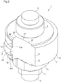
- a barrel shaft 1 according to a particular embodiment of the invention comprises two pivots 2, 3 for its pivoting in bearings of a clockwork movement about an axis A, a portion of square section 4 on which can be mounted a ratchet, two cylindrical portions 5, 6 for pivoting, respectively, a drum and a barrel cover, and a bung 7.
- the bung 7 carries a hook 8 for fixing the inner coil 9 d ' a spiral motor spring housed in the drum.
- the winding direction of the mainspring is shown at figure 2 by the arrow S.
- the bung 7 comprises a bearing surface 10 for the mainspring, on which the hook 8 is located.
- This bearing surface 10 extends, in the winding direction S of the driving spring, of a first bead 11 at a second edge 12.
- the bung 7 also comprises, upstream of the hook 8, a clearance 13 for receiving the inner end 14 of the motor spring, clearance whose wall 15 joins the first and second edges 11, 12.
- the hook 8 is intended to be engaged in an eyelet 16 of the inner coil 9 of the motor spring and is located, in the direction of the axis A, between two parts 10a, 10b of the bearing surface 10 to enable it to rotate.
- the hook 8 comprises two opposite end surfaces 17, 18. In the winding direction S, the end surface 18 is located upstream of the end wall. end surface 17 and at the level of the first edge 11. This extr surface emitted 18, preferably flat, serves to support the wall of the eyelet 16 when the mainspring is armed.
- the bearing surface 10 is composed of a first portion 19 extending from the first edge 11 and whose radius increases in the winding direction S, and a second portion 20 ' extending from the first portion 19 to the second edge 12 and whose radius is constant.
- the bearing surface 10 could, however, have another shape, for example being of increasing radius from the first edge 11 to the second edge 12.
- the wall 15 of the clearance 13 has itself a curved profile with a bump 21 in its part. central and two recesses 22, 23 in its two end portions.
- the recess 23 defines with the bearing surface 10 the first edge 11 and adjoins the base 24 and the end surface 18 of the hook 8.
- the wall 15 of the recess 13 could have, between the hollow 23 and the second edge 12, a straight profile.
- the recess 23 has an arcuate profile of radius R1 and its tangent plane at its line of junction with the end surface 18 of the hook 8 is the plane which contains said end surface 18.
- the hollow 23 joins the end surface 18 of the hook 8 to the rest of the wall 15 of the clearance 13 without forming of the edge with the end surface 18.
- the constraints that the base 24 of the hook 8 during the armature of the motor spring is therefore considerably reduced. This makes it possible to reduce the diameter of the barrel shaft 1.
- no edge is formed between the recess 23 and the second edge 12 in the clearance 13. In this way, the presence of any areas of weakness in the vicinity of the hook 8 is avoided.
- the radius R1 of the recess 23 is greater than or equal to 0.05 mm, or even 0.09 mm.
- the radius R1 may however be less than or equal to 0.5 mm.
- the radius R2 of the plug 7 is less than or equal to 1.15 mm, or even 1 mm, or even 0.85 mm.
- the radius R2 may however be greater than or equal to 0.75 mm.
- the radius R2 of the bung 7 is measured at the upstream end of the wall 15 of the clearance 13, that is to say that it is defined as the distance between the upstream end of the wall 15 of the clearance 13 and the axis A of the barrel shaft 1 and that it corresponds to the radius
- the upstream end of the wall 15 of the clearance 13 coincides with the downstream end of the bearing surface 10. In the example shown, these two ends are the second edge 12.
- the end surface 18 of the hook 8 may be slightly curved. In this case, not to form an edge between them, the end surface 18 and the recess 23 have their tangent planes at their junction line which are merged.
- the figure 3 illustrates a barrel shaft 1 'according to another embodiment of the invention.
- This barrel shaft 1 ' differs from the barrel shaft 1 of figures 1 and 2 by the shape of the clearance 13 'situated upstream of the hook 8.
- the wall 15' of the clearance 13 'successively comprises, between the first edge 11 and the second edge 12, a flat surface 22', an arcuate recess 23 ' and an upstream surface 24 'which is flat in the example shown but which could also be curved.
- the first edge 11 is thus the intersection between the flat surface 22 'and the bearing surface 10.
- the second edge 12 is the intersection between the upstream surface 24' and the bearing surface 10.
- the flat surface 22 ' is in the same plane as the end surface 18 of the hook 8 and thus defines an extension 25 'for the end surface 18.
- the tangent plane of the recess 23' at its junction line with the flat surface 22 ' is the plane that contains surfaces 18 and 22 '.
- the hollow 23 ' forms no edge with the flat surface 22'.
- no edge is formed between the hollow 23 'and the upstream surface 24'.
- the end surface 18 of the hook 8 and / or the extension 25 ' may be slightly curved (s).
- extension of a given surface is meant in the present invention a surface that adjoins the given surface without forming an edge with it.
- the radius of the hollow 23 ' can take the same values as those of the radius R1 illustrated in FIG. figure 2 .
- the radius of the bung 7, measured at the upstream end of the wall 15 'of the clearance 13', can take the same values as the radius R 2 illustrated in FIG. figure 2 .
- the second edge 12 could be removed.
- the upstream part of the wall 15, 15 'of the clearance 13, 13' and the downstream part of the bearing surface 10 could have their tangent planes at their junction line which are merged.
Landscapes
- Physics & Mathematics (AREA)
- General Physics & Mathematics (AREA)
- Springs (AREA)
- Connection Of Motors, Electrical Generators, Mechanical Devices, And The Like (AREA)
Description
- La présente invention concerne un arbre de barillet d'horlogerie.
- Dans un mouvement horloger mécanique, le barillet est l'organe moteur qui apporte l'énergie nécessaire au déplacement des différents composants. Le barillet comprend un tambour, un couvercle fermant le tambour, un arbre de barillet autour duquel pivotent librement le tambour et le couvercle, et un ressort moteur en spirale logé dans le tambour. La spire extérieure du ressort moteur est maintenue par la paroi du tambour. L'arbre de barillet comprend une partie appelée « bonde » qui porte un crochet auquel est attachée la spire intérieure du ressort moteur. L'arbre de barillet est solidaire en rotation d'un rochet et, par l'intermédiaire de ce rochet, peut être entraîné en rotation par une tige de remontoir (remontage manuel) ou une masse oscillante (remontage automatique) du mouvement pour armer le ressort moteur et accumuler ainsi de l'énergie.
- Dans les mouvements horlogers conventionnels, le dimensionnement de l'arbre de barillet lui permet de supporter les contraintes que lui fait subir le ressort moteur lors de l'armage de ce dernier. Cependant, un tel dimensionnement limite le volume disponible à l'intérieur du tambour pour loger le ressort moteur. Diminuer le diamètre de l'arbre de barillet permettrait d'augmenter le volume du ressort moteur, donc la durée de marche du mouvement. Mais une simple réduction homothétique de l'arbre de barillet ne convient pas, la résistance mécanique de l'arbre de barillet n'étant alors plus suffisante. Ce manque de résistance mécanique est d'autant plus problématique que, pour un même couple du ressort moteur, une diminution du diamètre de l'arbre de barillet entraîne une augmentation de la force appliquée au crochet.
- La présente invention vise à faciliter une réduction du diamètre de l'arbre de barillet et propose à cette fin un arbre de barillet d'horlogerie comprenant une bonde comprenant elle-même une surface d'appui pour une spire intérieure d'un ressort moteur, surface d'appui de laquelle fait saillie un crochet destiné à être engagé dans un oeillet de ladite spire intérieure, le crochet étant situé, dans la direction axiale de l'arbre de barillet, entre une première partie et une deuxième partie de la surface d'appui et comprenant une surface d'extrémité servant d'appui à la paroi de l'oeillet lors de l'armage du ressort moteur, la bonde comprenant, en amont du crochet dans le sens d'enroulement du ressort moteur, un dégagement destiné à recevoir l'extrémité intérieure du ressort moteur, caractérisé en ce que la paroi du dégagement comprend un creux en arc de cercle qui jouxte ladite surface d'extrémité ou un prolongement de ladite surface d'extrémité sans former d'arête avec ladite surface d'extrémité, respectivement avec ledit prolongement, pour diminuer les contraintes subies par le crochet lors de l'armage du ressort moteur.
- D'autres caractéristiques et avantages de la présente invention apparaîtront à la lecture de la description détaillée suivante faite en référence aux dessins annexés dans lesquels :
- la
figure 1 est une vue en perspective d'un arbre de barillet selon un mode de réalisation particulier de l'invention ; - la
figure 2 est une vue plane de dessus de l'arbre de barillet selon ledit mode de réalisation particulier, auquel est attachée la spire intérieure d'un ressort moteur (montrée partiellement) ; - la
figure 3 est une vue en perspective d'un arbre de barillet selon un autre mode de réalisation de l'invention. - En référence aux
figures 1 et2 , un arbre de barillet 1 selon un mode de réalisation particulier de l'invention comprend deux pivots 2, 3 pour son pivotement dans des paliers d'un mouvement horloger autour d'un axe A, une portion de section carrée 4 sur laquelle peut être monté un rochet, deux portions cylindriques 5, 6 pour le pivotement, respectivement, d'un tambour et d'un couvercle de barillet, et une bonde 7. La bonde 7 porte un crochet 8 pour la fixation de la spire intérieure 9 d'un ressort moteur en spirale logé dans le tambour. Le sens d'enroulement du ressort moteur est représenté à lafigure 2 par la flèche S. - Plus particulièrement, la bonde 7 comprend une surface d'appui 10 pour le ressort moteur, sur laquelle est situé le crochet 8. Cette surface d'appui 10 s'étend, dans le sens d'enroulement S du ressort moteur, d'une première arête 11 à une seconde arête 12. La bonde 7 comprend aussi, en amont du crochet 8, un dégagement 13 pour recevoir l'extrémité intérieure 14 du ressort moteur, dégagement dont la paroi 15 joint les première et seconde arêtes 11, 12. Le crochet 8 est destiné à être engagé dans un oeillet 16 de la spire intérieure 9 du ressort moteur et est situé, dans la direction de l'axe A, entre deux parties 10a, 10b de la surface d'appui 10 pour lui permettre d'être entouré sur tout son pourtour par la paroi de l'oeillet 16. Le crochet 8 comprend deux surfaces d'extrémité opposées 17, 18. Dans le sens d'enroulement S, la surface d'extrémité 18 est située en amont de la surface d'extrémité 17 et au niveau de la première arête 11. Cette surface d'extrémité 18, de préférence plane, sert d'appui à la paroi de l'oeillet 16 lorsque le ressort moteur est armé.
- Dans l'exemple illustré, la surface d'appui 10 est composée d'une première partie 19 s'étendant depuis la première arête 11 et dont le rayon croît dans le sens d'enroulement S, et d'une deuxième partie 20 s'étendant de la première partie 19 à la seconde arête 12 et dont le rayon est constant. La surface d'appui 10 pourrait toutefois avoir une autre forme, par exemple être de rayon croissant de la première arête 11 à la seconde arête 12. La paroi 15 du dégagement 13 a, elle, un profil courbe avec une bosse 21 dans sa partie centrale et deux creux 22, 23 dans ses deux parties d'extrémité. En particulier, le creux 23 définit avec la surface d'appui 10 la première arête 11 et jouxte la base 24 et la surface d'extrémité 18 du crochet 8. Dans une variante, la paroi 15 du dégagement 13 pourrait avoir, entre le creux 23 et la seconde arête 12, un profil droit.
- Le creux 23 a un profil en arc de cercle de rayon R1 et son plan tangent au niveau de sa ligne de jonction avec la surface d'extrémité 18 du crochet 8 est le plan qui contient ladite surface d'extrémité 18. Ainsi, le creux 23 joint la surface d'extrémité 18 du crochet 8 au reste de la paroi 15 du dégagement 13 sans former d'arête avec la surface d'extrémité 18. Les contraintes que subit la base 24 du crochet 8 lors de l'armage du ressort moteur sont donc considérablement réduites. Ceci rend possible une diminution du diamètre de l'arbre de barillet 1.
- En effet, sur les arbres de barillet conventionnels (sans le creux 23) la surface d'extrémité du crochet servant d'appui forme une arête avec la paroi du dégagement. Il a été constaté lors d'essais et de simulations que cette arête constitue une zone de faiblesse, ou zone de concentration de contraintes, qui empêche une diminution du diamètre de l'arbre de barillet. Par exemple, des essais ont été effectués par la demanderesse sur des arbres de barillet conventionnels dont le diamètre de la bonde avait été réduit de 2,35 mm à 1,60 mm, permettant un allongement du ressort moteur de 10,4 tours à 11,8 tours. Le couple appliqué était équivalent à dix fois le couple maximum du ressort moteur. Lors de ces essais, le crochet a été arraché après 30 cycles de remontage du ressort moteur, alors que dans les conditions sus-indiquées il est d'usage de garantir la tenue de l'arbre de barillet pendant 500 cycles. Les mêmes essais effectués sur l'arbre de barillet selon l'invention, muni du creux 23, ont permis de vérifier qu'il supporte les 500 cycles de remontage, voire plus de 1000 cycles, sans rupture du crochet.
- De préférence, comme représenté, aucune arête n'est formée entre le creux 23 et la seconde arête 12 dans le dégagement 13. De cette manière, on évite la présence d'éventuelles zones de faiblesse à proximité du crochet 8.
- De préférence, le rayon R1 du creux 23 est supérieur ou égal à 0,05 mm, voire à 0,09 mm. Le rayon R1 peut toutefois être inférieur ou égal à 0,5 mm.
- De préférence également, le rayon R2 de la bonde 7 est inférieur ou égal à 1,15 mm, voire à 1 mm, voire à 0,85 mm. Le rayon R2 peut toutefois être supérieur ou égal à 0,75 mm. Dans la présente invention, le rayon R2 de la bonde 7 est mesuré à l'extrémité amont de la paroi 15 du dégagement 13, c'est-à-dire qu'il est défini comme la distance entre l'extrémité amont de la paroi 15 du dégagement 13 et l'axe A de l'arbre de barillet 1 et qu'il correspond au rayon maximum de la bonde 7. L'extrémité amont de la paroi 15 du dégagement 13 coïncide avec l'extrémité aval de la surface d'appui 10. Dans l'exemple illustré, ces deux extrémités sont la seconde arête 12.
- Au lieu d'être plane, comme représenté, la surface d'extrémité 18 du crochet 8 peut être légèrement courbe. Dans ce cas, pour ne pas former d'arête entre elles, la surface d'extrémité 18 et le creux 23 ont leurs plans tangents au niveau de leur ligne de jonction qui sont confondus.
- La
figure 3 illustre un arbre de barillet 1' selon un autre mode de réalisation de l'invention. Cet arbre de barillet 1' diffère de l'arbre de barillet 1 desfigures 1 et2 par la forme du dégagement 13' situé en amont du crochet 8. La paroi 15' du dégagement 13' comprend successivement, entre la première arête 11 et la seconde arête 12, une surface plane 22', un creux en arc de cercle 23' et une surface amont 24' qui est plane dans l'exemple représenté mais qui pourrait aussi être courbe. La première arête 11 est ainsi l'intersection entre la surface plane 22' et la surface d'appui 10. La seconde arête 12 est l'intersection entre la surface amont 24' et la surface d'appui 10. La surface plane 22' est dans le même plan que la surface d'extrémité 18 du crochet 8 et définit ainsi un prolongement 25' pour la surface d'extrémité 18. Le plan tangent du creux 23' à sa ligne de jonction avec la surface plane 22' est le plan qui contient les surfaces 18 et 22'. Ainsi, le creux 23' ne forme aucune arête avec la surface plane 22'. De même, aucune arête n'est formée entre le creux 23' et la surface amont 24'. - La surface d'extrémité 18 du crochet 8 et/ou le prolongement 25' pourrai(en)t être légèrement courbe(s). Par « prolongement » d'une surface donnée on entend dans la présente invention une surface qui jouxte la surface donnée sans former d'arête avec elle.
- Le rayon du creux 23' peut prendre les mêmes valeurs que celles du rayon R1 illustré à la
figure 2 . De façon analogue, le rayon de la bonde 7, mesuré à l'extrémité amont de la paroi 15' du dégagement 13', peut prendre les mêmes valeurs que le rayon R2 illustré à lafigure 2 . - Dans chacun des modes de réalisation ci-dessus, la seconde arête 12 pourrait être supprimée. En d'autres termes, la partie amont de la paroi 15, 15' du dégagement 13, 13' et la partie aval de la surface d'appui 10 pourraient avoir leurs plans tangents au niveau de leur ligne de jonction qui sont confondus.
Claims (10)
- Arbre de barillet d'horlogerie (1) comprenant une bonde (7) comprenant elle-même une surface d'appui (10) pour une spire intérieure (9) d'un ressort moteur, surface d'appui (10) de laquelle fait saillie un crochet (8) destiné à être engagé dans un oeillet (16) de ladite spire intérieure (9) et comprenant une surface d'extrémité (18) servant d'appui à la paroi de l'oeillet (16) lors de l'armage du ressort moteur, la bonde (7) comprenant, en amont du crochet (8) dans le sens d'enroulement (S) du ressort moteur, un dégagement (13 ; 13') destiné à recevoir l'extrémité intérieure (14) du ressort moteur, caractérisé en ce que le crochet (8) est situé, dans la direction axiale (A) de l'arbre de barillet (1), entre une première partie (10a) et une deuxième partie (10b) de la surface d'appui (10) et en ce que la paroi (15 ; 15') du dégagement (13 ; 13') comprend un creux en arc de cercle (23 ; 23') qui jouxte ladite surface d'extrémité (18) ou un prolongement (25') de ladite surface d'extrémité (18) sans former d'arête avec ladite surface d'extrémité (18), respectivement avec ledit prolongement (25'), pour diminuer les contraintes subies par le crochet (8) lors de l'armage du ressort moteur.
- Arbre de barillet selon la revendication 1, caractérisé en ce que la paroi (15 ; 15') du dégagement (13 ; 13') est sans arête entre son extrémité amont (12) et le creux en arc de cercle (23 ; 23').
- Arbre de barillet selon la revendication 1 ou 2, caractérisé en ce que ladite surface d'extrémité (18) est plane.
- Arbre de barillet selon l'une quelconque des revendications 1 à 3, caractérisé en ce que le rayon (R1) du creux en arc de cercle (23 ; 23') est supérieur ou égal à 0,05 mm.
- Arbre de barillet selon la revendication 4, caractérisé en ce que le rayon (R1) du creux en arc de cercle (23 ; 23') est supérieur ou égal à 0,09 mm.
- Arbre de barillet selon la revendication 4 ou 5, caractérisé en ce que le rayon (R1) du creux en arc de cercle (23 ; 23') est inférieur ou égal à 0,5 mm.
- Arbre de barillet selon l'une quelconque des revendications 1 à 6, caractérisé en ce que le rayon (R2) de la bonde (7) tel que mesuré à l'extrémité amont (12) de la paroi (15 ; 15') du dégagement (13 ; 13') est inférieur ou égal à 1,15 mm.
- Arbre de barillet selon la revendication 7, caractérisé en ce que le rayon (R2) de la bonde (7) est inférieur ou égal à 1 mm.
- Arbre de barillet selon la revendication 8, caractérisé en ce que le rayon (R2) de la bonde (7) est inférieur ou égal à 0,85 mm.
- Arbre de barillet selon l'une quelconque des revendications 7 à 9, caractérisé en ce que le rayon (R2) de la bonde (7) est supérieur ou égal à 0,75 mm.
Applications Claiming Priority (2)
| Application Number | Priority Date | Filing Date | Title |
|---|---|---|---|
| EP15175608 | 2015-07-07 | ||
| PCT/EP2016/060274 WO2017005394A1 (fr) | 2015-07-07 | 2016-05-09 | Arbre de barillet d'horlogerie |
Publications (2)
| Publication Number | Publication Date |
|---|---|
| EP3320402A1 EP3320402A1 (fr) | 2018-05-16 |
| EP3320402B1 true EP3320402B1 (fr) | 2019-07-24 |
Family
ID=53514104
Family Applications (1)
| Application Number | Title | Priority Date | Filing Date |
|---|---|---|---|
| EP16720862.8A Active EP3320402B1 (fr) | 2015-07-07 | 2016-05-09 | Arbre de barillet d'horlogerie |
Country Status (3)
| Country | Link |
|---|---|
| EP (1) | EP3320402B1 (fr) |
| HK (1) | HK1247674B (fr) |
| WO (1) | WO2017005394A1 (fr) |
Families Citing this family (1)
| Publication number | Priority date | Publication date | Assignee | Title |
|---|---|---|---|---|
| WO2019207490A1 (fr) | 2018-04-26 | 2019-10-31 | Patek Philippe Sa Geneve | Barillet d'horlogerie et procede de modification de mouvement horloger |
Family Cites Families (3)
| Publication number | Priority date | Publication date | Assignee | Title |
|---|---|---|---|---|
| EP2657794B1 (fr) * | 2012-04-25 | 2017-02-01 | ETA SA Manufacture Horlogère Suisse | Arbre et ressort de barillet |
| CH706641A2 (fr) * | 2012-06-22 | 2013-12-31 | Cartier Creation Studio Sa | Organe moteur pour mouvement d'horlogerie. |
| EP2703908A1 (fr) * | 2012-08-30 | 2014-03-05 | ETA SA Manufacture Horlogère Suisse | Arbre de barillet d'horlogerie |
-
2016
- 2016-05-09 EP EP16720862.8A patent/EP3320402B1/fr active Active
- 2016-05-09 HK HK18107066.4A patent/HK1247674B/zh unknown
- 2016-05-09 WO PCT/EP2016/060274 patent/WO2017005394A1/fr not_active Ceased
Non-Patent Citations (1)
| Title |
|---|
| None * |
Also Published As
| Publication number | Publication date |
|---|---|
| WO2017005394A1 (fr) | 2017-01-12 |
| EP3320402A1 (fr) | 2018-05-16 |
| HK1247674B (zh) | 2020-04-03 |
Similar Documents
| Publication | Publication Date | Title |
|---|---|---|
| WO2010061251A1 (fr) | Organe moteur pour mouvement horloger | |
| EP2290477A1 (fr) | Ensemble de fixation de l'extrémite péripherique du spiral d'un dispositif à balancier-spiral pour pièce d'horlogerie | |
| EP2570862B1 (fr) | Ensemble barillet d'horlogerie à diamètre de bonde réduit | |
| EP1139182B1 (fr) | Mécanisme indicateur de réserve de marche et montre munie d'un tel mécanisme | |
| CH704250B1 (fr) | Mécanisme de transmission de mouvements axiaux et rotatifs entre deux axes décalés et pièce d'horlogerie comportant un tel mécanisme. | |
| EP3489766A1 (fr) | Mécanisme de correction d'une fonction d'un mouvement d'une pièce d'horlogerie | |
| EP2313812B1 (fr) | Mouvement pour piece d'horlogerie a dispositif de remontage automatique embarque | |
| WO2017005394A1 (fr) | Arbre de barillet d'horlogerie | |
| EP2834712A1 (fr) | Arbre de barillet pour mouvement horloger, ressort de barillet et barillet comprenant un tel ressort et/ou un tel arbre | |
| EP2570864A1 (fr) | Barillet d'horlogerie à diamètre de bonde réduit | |
| EP1562086B1 (fr) | Mécanisme indicateur de réserve de marche | |
| CH708811A2 (fr) | Dispositif de remontage automatique pour montre. | |
| EP3293585B1 (fr) | Porte-piton et procede de reglage de la position d'un piton dans un tel porte-piton | |
| EP0568499A1 (fr) | Dispositif indicateur de réserve de marche pour montre | |
| EP1923754B1 (fr) | Mouvement d'horlogerie équipé d'un module d'affichage | |
| EP3770694A1 (fr) | Stop-cage d'horlogerie comportant deux elements elastiques d'arret | |
| CH706543B1 (fr) | Mécanisme d'échappement d'horlogerie comportant des moyens de découplage entre le pignon et la roue d'échappement. | |
| EP2869139B1 (fr) | Mécanisme de tourbillon | |
| CH713951A2 (fr) | Barillet d'horlogerie à diamètre de bonde réduit. | |
| CH716092B1 (fr) | Barillet d'horlogerie et procédé de modification de mouvement horloger. | |
| EP2869134B1 (fr) | Système de barillet pour pièce d'horlogerie | |
| FR2497972A1 (fr) | Dispositif miniature d'etancheite entre un organe de commande exterieur et une boite en metal precieux de montre extra-plate | |
| EP3654109B1 (fr) | Pièce d'horlogerie comprenant deux sources d'énergie | |
| EP4560408A1 (fr) | Dispositif indicateur de réserve de marche pour une pièce d'horlogerie | |
| WO2004042478A2 (fr) | Dispositif d'accouplement d'un pignon |
Legal Events
| Date | Code | Title | Description |
|---|---|---|---|
| STAA | Information on the status of an ep patent application or granted ep patent |
Free format text: STATUS: THE INTERNATIONAL PUBLICATION HAS BEEN MADE |
|
| PUAI | Public reference made under article 153(3) epc to a published international application that has entered the european phase |
Free format text: ORIGINAL CODE: 0009012 |
|
| STAA | Information on the status of an ep patent application or granted ep patent |
Free format text: STATUS: REQUEST FOR EXAMINATION WAS MADE |
|
| 17P | Request for examination filed |
Effective date: 20171117 |
|
| AK | Designated contracting states |
Kind code of ref document: A1 Designated state(s): AL AT BE BG CH CY CZ DE DK EE ES FI FR GB GR HR HU IE IS IT LI LT LU LV MC MK MT NL NO PL PT RO RS SE SI SK SM TR |
|
| AX | Request for extension of the european patent |
Extension state: BA ME |
|
| RIN1 | Information on inventor provided before grant (corrected) |
Inventor name: CHABLOZ, DAVID |
|
| REG | Reference to a national code |
Ref country code: HK Ref legal event code: DE Ref document number: 1247674 Country of ref document: HK |
|
| DAV | Request for validation of the european patent (deleted) | ||
| DAX | Request for extension of the european patent (deleted) | ||
| GRAJ | Information related to disapproval of communication of intention to grant by the applicant or resumption of examination proceedings by the epo deleted |
Free format text: ORIGINAL CODE: EPIDOSDIGR1 |
|
| GRAP | Despatch of communication of intention to grant a patent |
Free format text: ORIGINAL CODE: EPIDOSNIGR1 |
|
| GRAP | Despatch of communication of intention to grant a patent |
Free format text: ORIGINAL CODE: EPIDOSNIGR1 |
|
| STAA | Information on the status of an ep patent application or granted ep patent |
Free format text: STATUS: GRANT OF PATENT IS INTENDED |
|
| INTG | Intention to grant announced |
Effective date: 20190221 |
|
| GRAJ | Information related to disapproval of communication of intention to grant by the applicant or resumption of examination proceedings by the epo deleted |
Free format text: ORIGINAL CODE: EPIDOSDIGR1 |
|
| STAA | Information on the status of an ep patent application or granted ep patent |
Free format text: STATUS: REQUEST FOR EXAMINATION WAS MADE |
|
| GRAR | Information related to intention to grant a patent recorded |
Free format text: ORIGINAL CODE: EPIDOSNIGR71 |
|
| GRAS | Grant fee paid |
Free format text: ORIGINAL CODE: EPIDOSNIGR3 |
|
| STAA | Information on the status of an ep patent application or granted ep patent |
Free format text: STATUS: GRANT OF PATENT IS INTENDED |
|
| INTC | Intention to grant announced (deleted) | ||
| GRAA | (expected) grant |
Free format text: ORIGINAL CODE: 0009210 |
|
| STAA | Information on the status of an ep patent application or granted ep patent |
Free format text: STATUS: THE PATENT HAS BEEN GRANTED |
|
| AK | Designated contracting states |
Kind code of ref document: B1 Designated state(s): AL AT BE BG CH CY CZ DE DK EE ES FI FR GB GR HR HU IE IS IT LI LT LU LV MC MK MT NL NO PL PT RO RS SE SI SK SM TR |
|
| INTG | Intention to grant announced |
Effective date: 20190614 |
|
| REG | Reference to a national code |
Ref country code: GB Ref legal event code: FG4D Free format text: NOT ENGLISH |
|
| REG | Reference to a national code |
Ref country code: CH Ref legal event code: EP |
|
| REG | Reference to a national code |
Ref country code: DE Ref legal event code: R096 Ref document number: 602016017319 Country of ref document: DE |
|
| REG | Reference to a national code |
Ref country code: AT Ref legal event code: REF Ref document number: 1158914 Country of ref document: AT Kind code of ref document: T Effective date: 20190815 |
|
| REG | Reference to a national code |
Ref country code: IE Ref legal event code: FG4D Free format text: LANGUAGE OF EP DOCUMENT: FRENCH |
|
| REG | Reference to a national code |
Ref country code: CH Ref legal event code: NV Representative=s name: MICHELI AND CIE SA, CH |
|
| REG | Reference to a national code |
Ref country code: NL Ref legal event code: MP Effective date: 20190724 |
|
| REG | Reference to a national code |
Ref country code: LT Ref legal event code: MG4D |
|
| REG | Reference to a national code |
Ref country code: AT Ref legal event code: MK05 Ref document number: 1158914 Country of ref document: AT Kind code of ref document: T Effective date: 20190724 |
|
| PG25 | Lapsed in a contracting state [announced via postgrant information from national office to epo] |
Ref country code: LT Free format text: LAPSE BECAUSE OF FAILURE TO SUBMIT A TRANSLATION OF THE DESCRIPTION OR TO PAY THE FEE WITHIN THE PRESCRIBED TIME-LIMIT Effective date: 20190724 Ref country code: HR Free format text: LAPSE BECAUSE OF FAILURE TO SUBMIT A TRANSLATION OF THE DESCRIPTION OR TO PAY THE FEE WITHIN THE PRESCRIBED TIME-LIMIT Effective date: 20190724 Ref country code: SE Free format text: LAPSE BECAUSE OF FAILURE TO SUBMIT A TRANSLATION OF THE DESCRIPTION OR TO PAY THE FEE WITHIN THE PRESCRIBED TIME-LIMIT Effective date: 20190724 Ref country code: BG Free format text: LAPSE BECAUSE OF FAILURE TO SUBMIT A TRANSLATION OF THE DESCRIPTION OR TO PAY THE FEE WITHIN THE PRESCRIBED TIME-LIMIT Effective date: 20191024 Ref country code: NL Free format text: LAPSE BECAUSE OF FAILURE TO SUBMIT A TRANSLATION OF THE DESCRIPTION OR TO PAY THE FEE WITHIN THE PRESCRIBED TIME-LIMIT Effective date: 20190724 Ref country code: PT Free format text: LAPSE BECAUSE OF FAILURE TO SUBMIT A TRANSLATION OF THE DESCRIPTION OR TO PAY THE FEE WITHIN THE PRESCRIBED TIME-LIMIT Effective date: 20191125 Ref country code: NO Free format text: LAPSE BECAUSE OF FAILURE TO SUBMIT A TRANSLATION OF THE DESCRIPTION OR TO PAY THE FEE WITHIN THE PRESCRIBED TIME-LIMIT Effective date: 20191024 Ref country code: FI Free format text: LAPSE BECAUSE OF FAILURE TO SUBMIT A TRANSLATION OF THE DESCRIPTION OR TO PAY THE FEE WITHIN THE PRESCRIBED TIME-LIMIT Effective date: 20190724 Ref country code: AT Free format text: LAPSE BECAUSE OF FAILURE TO SUBMIT A TRANSLATION OF THE DESCRIPTION OR TO PAY THE FEE WITHIN THE PRESCRIBED TIME-LIMIT Effective date: 20190724 |
|
| PG25 | Lapsed in a contracting state [announced via postgrant information from national office to epo] |
Ref country code: RS Free format text: LAPSE BECAUSE OF FAILURE TO SUBMIT A TRANSLATION OF THE DESCRIPTION OR TO PAY THE FEE WITHIN THE PRESCRIBED TIME-LIMIT Effective date: 20190724 Ref country code: IS Free format text: LAPSE BECAUSE OF FAILURE TO SUBMIT A TRANSLATION OF THE DESCRIPTION OR TO PAY THE FEE WITHIN THE PRESCRIBED TIME-LIMIT Effective date: 20191124 Ref country code: LV Free format text: LAPSE BECAUSE OF FAILURE TO SUBMIT A TRANSLATION OF THE DESCRIPTION OR TO PAY THE FEE WITHIN THE PRESCRIBED TIME-LIMIT Effective date: 20190724 Ref country code: ES Free format text: LAPSE BECAUSE OF FAILURE TO SUBMIT A TRANSLATION OF THE DESCRIPTION OR TO PAY THE FEE WITHIN THE PRESCRIBED TIME-LIMIT Effective date: 20190724 Ref country code: GR Free format text: LAPSE BECAUSE OF FAILURE TO SUBMIT A TRANSLATION OF THE DESCRIPTION OR TO PAY THE FEE WITHIN THE PRESCRIBED TIME-LIMIT Effective date: 20191025 Ref country code: AL Free format text: LAPSE BECAUSE OF FAILURE TO SUBMIT A TRANSLATION OF THE DESCRIPTION OR TO PAY THE FEE WITHIN THE PRESCRIBED TIME-LIMIT Effective date: 20190724 |
|
| PG25 | Lapsed in a contracting state [announced via postgrant information from national office to epo] |
Ref country code: TR Free format text: LAPSE BECAUSE OF FAILURE TO SUBMIT A TRANSLATION OF THE DESCRIPTION OR TO PAY THE FEE WITHIN THE PRESCRIBED TIME-LIMIT Effective date: 20190724 |
|
| PG25 | Lapsed in a contracting state [announced via postgrant information from national office to epo] |
Ref country code: PL Free format text: LAPSE BECAUSE OF FAILURE TO SUBMIT A TRANSLATION OF THE DESCRIPTION OR TO PAY THE FEE WITHIN THE PRESCRIBED TIME-LIMIT Effective date: 20190724 Ref country code: DK Free format text: LAPSE BECAUSE OF FAILURE TO SUBMIT A TRANSLATION OF THE DESCRIPTION OR TO PAY THE FEE WITHIN THE PRESCRIBED TIME-LIMIT Effective date: 20190724 Ref country code: EE Free format text: LAPSE BECAUSE OF FAILURE TO SUBMIT A TRANSLATION OF THE DESCRIPTION OR TO PAY THE FEE WITHIN THE PRESCRIBED TIME-LIMIT Effective date: 20190724 Ref country code: RO Free format text: LAPSE BECAUSE OF FAILURE TO SUBMIT A TRANSLATION OF THE DESCRIPTION OR TO PAY THE FEE WITHIN THE PRESCRIBED TIME-LIMIT Effective date: 20190724 |
|
| PG25 | Lapsed in a contracting state [announced via postgrant information from national office to epo] |
Ref country code: SM Free format text: LAPSE BECAUSE OF FAILURE TO SUBMIT A TRANSLATION OF THE DESCRIPTION OR TO PAY THE FEE WITHIN THE PRESCRIBED TIME-LIMIT Effective date: 20190724 Ref country code: SK Free format text: LAPSE BECAUSE OF FAILURE TO SUBMIT A TRANSLATION OF THE DESCRIPTION OR TO PAY THE FEE WITHIN THE PRESCRIBED TIME-LIMIT Effective date: 20190724 Ref country code: IS Free format text: LAPSE BECAUSE OF FAILURE TO SUBMIT A TRANSLATION OF THE DESCRIPTION OR TO PAY THE FEE WITHIN THE PRESCRIBED TIME-LIMIT Effective date: 20200224 Ref country code: CZ Free format text: LAPSE BECAUSE OF FAILURE TO SUBMIT A TRANSLATION OF THE DESCRIPTION OR TO PAY THE FEE WITHIN THE PRESCRIBED TIME-LIMIT Effective date: 20190724 |
|
| REG | Reference to a national code |
Ref country code: DE Ref legal event code: R097 Ref document number: 602016017319 Country of ref document: DE |
|
| PLBE | No opposition filed within time limit |
Free format text: ORIGINAL CODE: 0009261 |
|
| STAA | Information on the status of an ep patent application or granted ep patent |
Free format text: STATUS: NO OPPOSITION FILED WITHIN TIME LIMIT |
|
| PG2D | Information on lapse in contracting state deleted |
Ref country code: IS |
|
| 26N | No opposition filed |
Effective date: 20200603 |
|
| PG25 | Lapsed in a contracting state [announced via postgrant information from national office to epo] |
Ref country code: SI Free format text: LAPSE BECAUSE OF FAILURE TO SUBMIT A TRANSLATION OF THE DESCRIPTION OR TO PAY THE FEE WITHIN THE PRESCRIBED TIME-LIMIT Effective date: 20190724 |
|
| PG25 | Lapsed in a contracting state [announced via postgrant information from national office to epo] |
Ref country code: MC Free format text: LAPSE BECAUSE OF FAILURE TO SUBMIT A TRANSLATION OF THE DESCRIPTION OR TO PAY THE FEE WITHIN THE PRESCRIBED TIME-LIMIT Effective date: 20190724 |
|
| REG | Reference to a national code |
Ref country code: BE Ref legal event code: MM Effective date: 20200531 |
|
| PG25 | Lapsed in a contracting state [announced via postgrant information from national office to epo] |
Ref country code: LU Free format text: LAPSE BECAUSE OF NON-PAYMENT OF DUE FEES Effective date: 20200509 |
|
| PG25 | Lapsed in a contracting state [announced via postgrant information from national office to epo] |
Ref country code: IE Free format text: LAPSE BECAUSE OF NON-PAYMENT OF DUE FEES Effective date: 20200509 |
|
| PG25 | Lapsed in a contracting state [announced via postgrant information from national office to epo] |
Ref country code: BE Free format text: LAPSE BECAUSE OF NON-PAYMENT OF DUE FEES Effective date: 20200531 |
|
| PG25 | Lapsed in a contracting state [announced via postgrant information from national office to epo] |
Ref country code: MT Free format text: LAPSE BECAUSE OF FAILURE TO SUBMIT A TRANSLATION OF THE DESCRIPTION OR TO PAY THE FEE WITHIN THE PRESCRIBED TIME-LIMIT Effective date: 20190724 Ref country code: CY Free format text: LAPSE BECAUSE OF FAILURE TO SUBMIT A TRANSLATION OF THE DESCRIPTION OR TO PAY THE FEE WITHIN THE PRESCRIBED TIME-LIMIT Effective date: 20190724 |
|
| PG25 | Lapsed in a contracting state [announced via postgrant information from national office to epo] |
Ref country code: MK Free format text: LAPSE BECAUSE OF FAILURE TO SUBMIT A TRANSLATION OF THE DESCRIPTION OR TO PAY THE FEE WITHIN THE PRESCRIBED TIME-LIMIT Effective date: 20190724 |
|
| P01 | Opt-out of the competence of the unified patent court (upc) registered |
Effective date: 20230521 |
|
| PGFP | Annual fee paid to national office [announced via postgrant information from national office to epo] |
Ref country code: FR Payment date: 20240321 Year of fee payment: 9 |
|
| PGFP | Annual fee paid to national office [announced via postgrant information from national office to epo] |
Ref country code: IT Payment date: 20240411 Year of fee payment: 9 |
|
| PGFP | Annual fee paid to national office [announced via postgrant information from national office to epo] |
Ref country code: DE Payment date: 20250311 Year of fee payment: 10 |
|
| PGFP | Annual fee paid to national office [announced via postgrant information from national office to epo] |
Ref country code: CH Payment date: 20250601 Year of fee payment: 10 |
|
| PGFP | Annual fee paid to national office [announced via postgrant information from national office to epo] |
Ref country code: GB Payment date: 20260312 Year of fee payment: 11 |
|
| PG25 | Lapsed in a contracting state [announced via postgrant information from national office to epo] |
Ref country code: IT Free format text: LAPSE BECAUSE OF NON-PAYMENT OF DUE FEES Effective date: 20250509 |
|
| PG25 | Lapsed in a contracting state [announced via postgrant information from national office to epo] |
Ref country code: FR Free format text: LAPSE BECAUSE OF NON-PAYMENT OF DUE FEES Effective date: 20250531 |