EP3320200B1 - A method of and a control system for determining an offset relating to crank angle measurement - Google Patents
A method of and a control system for determining an offset relating to crank angle measurement Download PDFInfo
- Publication number
- EP3320200B1 EP3320200B1 EP15788450.3A EP15788450A EP3320200B1 EP 3320200 B1 EP3320200 B1 EP 3320200B1 EP 15788450 A EP15788450 A EP 15788450A EP 3320200 B1 EP3320200 B1 EP 3320200B1
- Authority
- EP
- European Patent Office
- Prior art keywords
- cylinder
- crank angle
- pressure
- mean effective
- indicated mean
- Prior art date
- Legal status (The legal status is an assumption and is not a legal conclusion. Google has not performed a legal analysis and makes no representation as to the accuracy of the status listed.)
- Active
Links
- 238000000034 method Methods 0.000 title claims description 36
- 238000005259 measurement Methods 0.000 title claims description 21
- 238000002485 combustion reaction Methods 0.000 claims description 57
- 239000000446 fuel Substances 0.000 claims description 16
- 238000007906 compression Methods 0.000 claims description 6
- 238000009530 blood pressure measurement Methods 0.000 claims description 3
- 238000012937 correction Methods 0.000 claims description 2
- 230000006835 compression Effects 0.000 description 4
- 230000000977 initiatory effect Effects 0.000 description 2
- 230000010363 phase shift Effects 0.000 description 2
- 230000035945 sensitivity Effects 0.000 description 2
- 238000004891 communication Methods 0.000 description 1
- 238000001514 detection method Methods 0.000 description 1
- 238000011161 development Methods 0.000 description 1
- 230000018109 developmental process Effects 0.000 description 1
- 238000010586 diagram Methods 0.000 description 1
- 230000000694 effects Effects 0.000 description 1
- 230000007613 environmental effect Effects 0.000 description 1
- 238000012986 modification Methods 0.000 description 1
- 230000004048 modification Effects 0.000 description 1
Images

Classifications
-
- F—MECHANICAL ENGINEERING; LIGHTING; HEATING; WEAPONS; BLASTING
- F02—COMBUSTION ENGINES; HOT-GAS OR COMBUSTION-PRODUCT ENGINE PLANTS
- F02D—CONTROLLING COMBUSTION ENGINES
- F02D41/00—Electrical control of supply of combustible mixture or its constituents
- F02D41/009—Electrical control of supply of combustible mixture or its constituents using means for generating position or synchronisation signals
-
- F—MECHANICAL ENGINEERING; LIGHTING; HEATING; WEAPONS; BLASTING
- F02—COMBUSTION ENGINES; HOT-GAS OR COMBUSTION-PRODUCT ENGINE PLANTS
- F02D—CONTROLLING COMBUSTION ENGINES
- F02D35/00—Controlling engines, dependent on conditions exterior or interior to engines, not otherwise provided for
- F02D35/02—Controlling engines, dependent on conditions exterior or interior to engines, not otherwise provided for on interior conditions
- F02D35/023—Controlling engines, dependent on conditions exterior or interior to engines, not otherwise provided for on interior conditions by determining the cylinder pressure
-
- F—MECHANICAL ENGINEERING; LIGHTING; HEATING; WEAPONS; BLASTING
- F02—COMBUSTION ENGINES; HOT-GAS OR COMBUSTION-PRODUCT ENGINE PLANTS
- F02D—CONTROLLING COMBUSTION ENGINES
- F02D41/00—Electrical control of supply of combustible mixture or its constituents
- F02D41/24—Electrical control of supply of combustible mixture or its constituents characterised by the use of digital means
- F02D41/2406—Electrical control of supply of combustible mixture or its constituents characterised by the use of digital means using essentially read only memories
- F02D41/2425—Particular ways of programming the data
- F02D41/2429—Methods of calibrating or learning
- F02D41/2451—Methods of calibrating or learning characterised by what is learned or calibrated
- F02D41/2474—Characteristics of sensors
-
- F—MECHANICAL ENGINEERING; LIGHTING; HEATING; WEAPONS; BLASTING
- F02—COMBUSTION ENGINES; HOT-GAS OR COMBUSTION-PRODUCT ENGINE PLANTS
- F02D—CONTROLLING COMBUSTION ENGINES
- F02D41/00—Electrical control of supply of combustible mixture or its constituents
- F02D41/02—Circuit arrangements for generating control signals
- F02D41/04—Introducing corrections for particular operating conditions
- F02D41/042—Introducing corrections for particular operating conditions for stopping the engine
-
- F—MECHANICAL ENGINEERING; LIGHTING; HEATING; WEAPONS; BLASTING
- F02—COMBUSTION ENGINES; HOT-GAS OR COMBUSTION-PRODUCT ENGINE PLANTS
- F02D—CONTROLLING COMBUSTION ENGINES
- F02D41/00—Electrical control of supply of combustible mixture or its constituents
- F02D41/02—Circuit arrangements for generating control signals
- F02D41/14—Introducing closed-loop corrections
- F02D41/1497—With detection of the mechanical response of the engine
Definitions
- US 4944271 discloses a manner of correcting the pressure measurement by an offset of the pressure sensing means, which is determined by comparing the pressure in the cylinder, as detected by the pressure sensing means at the time when the crank is at the top dead center position as detected by the crank angle sensor, with the product of the compression ratio of the engine and the manifold pressure as detected by the manifold pressure sensor. An additional procedure for compensating the effects of temperature is also disclosed.
Landscapes
- Engineering & Computer Science (AREA)
- Chemical & Material Sciences (AREA)
- Combustion & Propulsion (AREA)
- Mechanical Engineering (AREA)
- General Engineering & Computer Science (AREA)
- Analytical Chemistry (AREA)
- Combined Controls Of Internal Combustion Engines (AREA)
Description
- The present invention relates to method of determining an offset relating to crank angle measurement in connection with a cylinder of an internal combustion piston engine. Invention relates also to control system for determining an offset relating to crank angle measurement in connection with a cylinder of an internal combustion piston engine.
- Environmental issues in the field of internal combustion piston have an ever increasing role in the developments in the field. The stringent demands of the present regulations and expectation require use of accurate control system for operating the engines. In order to provide an accurate control system one needs to have reliable information from the circumstances of the engine as feedback for the control.
- One of the most valuable combustion parameters related to internal combustion engines is the indicated mean effective pressure (IMEP). Often-times IMEP is calculated in a cylinder-wise manner based on measurement of the cylinder pressure.
- In the document
US 4944271 there is described a controller for controlling the combustion of an internal combustion engine. The controller controls the combustion on the basis of certain drive control parameters, such as the ignition timing and the air-fuel ratio, so as to optimize in terms of the driving performance the values and ranges of fluctuation of certain combustion parameters. Combustion parameters, which are used to control the combustion process in an internal combustion engine include e.g. maximum combustion pressure, crank angle at the time of achieving the maximum combustion pressure, maximum rise rate of the combustion pressure, and indicated mean effective pressure. These combustion parameters are determined by the controller on the basis of the pressure profile in the cylinders of the engine which is detected by a pressure sensor. - Since the pressure sensor is directly attached to the engine, it is subjected to significant changes in temperature, resulting in a tendency to deteriorate with age. In view of this, as well as its initial instability, the accurate detection of the pressure achieved by the sensor is in practice cumbersome.
-
US 4944271 discloses a manner of correcting the pressure measurement by an offset of the pressure sensing means, which is determined by comparing the pressure in the cylinder, as detected by the pressure sensing means at the time when the crank is at the top dead center position as detected by the crank angle sensor, with the product of the compression ratio of the engine and the manifold pressure as detected by the manifold pressure sensor. An additional procedure for compensating the effects of temperature is also disclosed. -
DE 10 2012 023834 A1 -
US 2013 060447 A1 discloses a method of determining an offset relating to crank angle measurement in connection with a cylinder of an internal combustion piston engine, in which the offset is determined based on an integral value of indicated mean effective pressure in the cylinder at an engine top dead center. - An object of the invention is to provide a method of determining an offset relating to crank angle measurement in connection with a cylinder of an internal combustion piston engine according to the engine in which the performance is considerably improved compared to the prior art solutions.
- It is also an object of the invention to provide control system for determining an offset relating to crank angle measurement in connection with a cylinder of an internal combustion piston engine which improves the performance considerably compared to the prior art solutions.
- The objects of the invention can be met substantially as is disclosed in the independent claims and in the other claims describing more details of different embodiments of the invention.
- When practising the method of determining an offset relating to crank angle measurement in connection with a cylinder of an internal combustion piston engine according to the engine
- the engine is rotated and it is refrained from fuel combustion in the cylinder,
- a reference value for the indicated mean effective pressure is determined
- an integral value of indicated mean effective pressure in the cylinder is determined over a range of crank angle during the combustion chamber of the cylinder is closed, and wherein a dead center position of the piston is located symmetrically within the range, and
- a crank angle position offset value is determined based on the determined integral value of indicated mean effective pressure and the reference value for the indicated mean effective pressure.
- The crank angle position offset value makes it possible increase the accuracy of defining the actual IMEP value by means of which it is possible to further improve the control of combustion process in the internal combustion engine. Particularly it is possible tackle with the differences between the dynamics of the cylinder pressure sensors.
- The step of is refraining from fuel combustion in the cylinder may comprise actively controlling the cease of fuel combustion, or making use of a stage of the engine cycle where no combustion takes place, as will become apparent later in the disclosure,
- According to an embodiment of the invention the method is used for calibrating the crank angle position measurement such that the crank angle position offset value is used for correction of the crank angle position measurement value.
- According to an embodiment of the invention the method is used as diagnosing the position offset in the cylinder pressure measurement.
- The combustion chamber of the cylinder is closed in a four stoke engine when all of the gas exchange valves of the cylinder are maintained closed. The combustion chamber is the space limited by the side walls of the cylinder, top wall of the cylinder or a cylinder head and the top of the piston.
- According to the invention the dead center position is a bottom dead center position and all of the intake valves of the cylinder are closed so that during the method all of the gas exchange valves are maintained closed.
- According to an embodiment of the invention the integral value of indicated mean effective pressure in the cylinder is determined by using a formula

- IMEP = the integral value of indicated mean effective pressure
- θ1 = start angle of the range
- θ2 = end angle of the range
- VR = volume of the cylinder swept by the piston when the engine is rotated over the range of crank angle θ1 to θ2
- p = measured pressure in the cylinder derivative of the cylinder volume

- According to the invention the crank angle range between the start angle and the end angle is symmetrical over the dead center position. This way the offset value is easily determined because the reference value for the indicated mean effective pressure is zero.
- This provides a device for an which performance is considerably improved. Normally the position calibration, i.e. phase synchronisation between cylinder pressure and cylinder volume is done according to the position of the flywheel, however this calibration is accurate only to a certain degree. Other factors that can have influence on the calibration are e.g. measurements delay in the measurement system. With the present invention the accuracy can be considerably improved.
- In the following, the invention will be described with reference to the accompanying exemplary, schematic drawings, in which
-
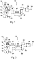
Figure 1 illustrates a control system in an internal combustion piston engine according to an example not part of the invention, -
Figure 2 illustrates a control system in an internal combustion piston engine according to the invention, -
Figure 3 illustrates an example not part of the invention, and -
Figure 4 illustrates an example of operation of the invention. -
Figures 1 and 2 depict schematically a control system according to respectively an example not part of the present invention and an embodiment of the invention adapted in connection with an internalcombustion piston engine 10. Theengine 10 is depicted in extremely simplified manner referring to only one of the cylinders of the engine. The present invention provides a method of and a control system for determining a offset relating to crank angle measurement in connection with a combustion control system of the engine, which can be used for providing more accurate control of the engine. - As is known as such the main components of the engine are one or
more cylinders 12 and apiston 14 arranged to reciprocate in thecylinder 12. The gas exchange in thecylinder 12 is controlled bygas exchange valves intake valve 24 and at least oneexhaust valve 22. Each of thepistons 14 is connected to acrank shaft 16 by a connectingrod 18. Thus, the mechanical dimensioning of parts defines geometry of thecombustion chamber 20 and also the volume swept by the piston when moving between its top dead center and bottom dead center. - The
control system 11 for determining an offset relating to crank angle measurement in connection with a combustion control system of theengine 10 comprises acylinder pressure sensor 26 adapted to measure the pressure in thecombustion chamber 20 of thecylinder 12 and to provide a pressure signal. There is also a crank shaft position sensor i.e.crank angle sensor 28 provided in the control system to provide a signal indicative to the position of thecrank shaft 16. - The control system is further provided with a cylinder
volume determination unit 30, which is adapted to receive the signal indicative to the position of thecrank shaft 16 from thecrank angle sensor 28. The cylindervolume determination unit 30 comprises executable instructions to convert the position signal into respective cylinder volume. That may be based on a predetermined lookup table or a function for numerical calculation belonging to the instructions. The cylindervolume determination unit 30 is adapted to provide a signal indicative to the volume of the cylinder at respective crank angle. - The
control system 11 comprises also an indicated mean effective pressure (IMEP)determination unit 32, which is in the following called as IMEP-unit 32. The IMEP-unit 32 is connected to thecylinder pressure sensor 26 and adapted to receive the pressure signal from thecylinder pressure sensor 26. The IMEP-unit 32 is also connected to the cylindervolume determination unit 30 and adapted to receive the signal indicative to the volume of the cylinder. The IMEP-unit 32 is further connected to thecrank angle sensor 28 and adapted to receive the signal indicative to the position of thecrank shaft 16 from thecrank angle sensor 28. The IMEP-unit 32 is provided with executable instructions to determine an integral value of indicated mean effective pressure in thecylinder 12. Particularly the instructions comprises instructions to determine the integral value of indicated mean effective pressure by using a formula
- IMEP = the integral value of indicated mean effective pressure
- θ1 = start crank angle of the used range
- θ2 = end crank angle of the used range
- VR = volume of the cylinder swept by the piston when the engine is rotated over the range of crank angle θ1 to θ2, obtainable from the cylinder
volume determination unit 30 - p = measured pressure in the cylinder, obtainable from the cylinder pressure sensor 26

- The control system is further provided with a
controller unit 36 and aset point unit 34. Theset point unit 34 is adapted to provide a reference value for thecontroller unit 36. Thecontroller unit 36 connected to theset point unit 34 and to the IMEP-unit 32. Thecontroller unit 36 is adapted to receive the integral value of indicated mean effective pressure from the IMEP-unit 32 and a reference value provided by theset point unit 34. Thecontroller unit 36 is provided with executable instructions to provide a crank angle position offset value as itsoutput 38. The reference value provided by set point unit represents the target integral value of indicated mean effective pressure for a given crank angle range and the integral value of indicated mean effective pressure from the IMEP-unit 32 represents a feedback value from the engine. -
Figure 1 refers to acontrol system 11 for determining an offset relating to crank angle range within which the piston is passing by the top dead center position. In order to make use of the control system when the piston is passing the top dead center the control system is provided instructions to disable the fuel admission to thecylinder 12 during the determination of the offset. According to an embodiment of the invention the IMEP-unit 32 is adapted to provide an output signal, which is depicted byline 33 extending from the IMEP-unit to afuel injector 23, based on which the combustion control system (not shown) of the engine misses out the fuel admission into and/or ignition in the combustion chamber. This may be accomplished by controlling thefuel injector 23 not to inject any fuel during the cycle in question. Thus, when practising the method it is refrained from bringing fuel into the cylinder and/or initiating the combustion. - It is also conceivable to perform the method while the engine is still rotating due to its inertia but the fuel admission has been halted for stopping the engine. Thus the determination of the offset is performed during the
intake valve 24 and theexhaust valve 22 are simultaneously closed and no combustion takes place and/or combustion of fuel is disabled during the method. -
Figure 2 refers to acontrol system 11 for determining an offset relating to crank angle range where the piston is passing by the bottom dead center. According to a first embodiment of the invention, in order to make use of the control system when the piston is passing the bottom dead center, the control system is provided with instructions to close theintake valve 24 and maintain thevalve 24 closed during the determination of the offset. Now thecylinder 12 is in the stage of intake - compression stroke and therefore the exhaust valve(s) 22 are closed in any case based on the normal control of the gas exchange valves. According to this embodiment of the invention the IMEP-unit 32 is adapted to provide an output signal, which is depicted by line 33' extending between the IMEP-unit 32 and theintake valve 24 control system, based on which the combustion control system (not shown) of the engine controls theintake valve 24 to close while the method is practised. Thus the determination of the offset is performed during theintake valve 24 and theexhaust valve 22 i.e. all the gas exchange valve are simultaneously closed and no combustion takes place and/or combustion of fuel is disabled during the method. - According to a second embodiment of the invention, in order to make use of the control system when the piston is passing the bottom dead center, the control system is provided with instructions to perform the determination of the offset during the
intake valve 24 and theexhaust valve 22 are simultaneously closed. Since thecylinder 12 is in the stage of intake - compression stroke, the exhaust valve(s) 22 are closed in any case based on the normal control of the gas exchange valves. In this embodiment theintake valve 24 is closed early before the bottom dead center for other reasons, and the information that the valve(s) is closed is transmitted to the IMEP-unit 32 via a communication line 33' and is used as signal allowing the initiation of determination of the offset value. - Even if the embodiments for determining the offset value in the proximity of top dead center and bottom dead center are disclosed separately it is conceivable to provide an engine with both alternatives. In that case the determination of the offset value may be practised using either of the means depending e.g. on operational circumstances of the engine. For example at high loads of the engine the early closure of the intake valve is more suitable way than providing a misfire in cylinder.
- The control system operates as is disclosed in the following explaining the method of determining an offset relating to crank angle measurement in connection with a cylinder of an internal combustion piston engine. In the method of determining an offset relating to crank angle measurement in connection with a cylinder of an internal combustion piston engine, the following steps are involved. Firstly, it is essential that the engine rotates or is made to rotate at least over a predetermined crank angle range and at least the cylinder in connection with which the method is practised such that is refrained from fuel combustion during the practising of the method. For purpose of practising the method a reference value for the indicated mean effective pressure is determined by the
set point unit 34. An integral value of indicated mean effective pressure in the cylinder is determined over a range of crank angle, during which the combustion chamber is closed i.e. all of the gas exchange valves of the cylinder are maintained closed, wherein a dead center position of the piston is located with the range, and the crank angle position offset value is determined based on the determined integral value of indicated mean effective pressure and the reference value for the indicated mean effective pressure. - The basic principle of the method is explained in the following with the reference to the
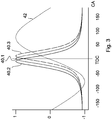
Figure 3 . In this case the method is practised over a range where the top dead center TDC of the piston is located.Figure 3 shows a chart where the horizontal axis depict the crank angle (CA) in degrees and the vertical axis represents normalized value of the variables, which are the derivative of thecylinder volume 42 and three different situations of measured pressure in 40.1,40.2,40.3 the cylinder while it is refrained from fuel combustion during the practising of the method. In other words the engine is so called motored. As an example, here the start angle θ1 of the range is 180 degrees before the top dead center and the end angle θ2 of the range is 180 degrees after the top dead center. It should be noted that the used range may be varied as long as the combustion chamber is closed by the gas exchange valves. However, if the range is too narrow the sensitivity of the calculations to disturbances is increased. The integral value of indicated mean effective pressure is determined by the formula above. - The method is practised when the crank angle range is symmetrical over the dead center position. In this case the start crank angle is as much before the dead center position as the end crank angle is after the dead center position, and the reference value is zero. Thus, the deviation of the integral value of indicated mean effective pressure from zero reveals the offset status. The formula can be interpreted as a sum of products of cylinder pressure and derivative of the cylinder volume, and it can be seen that zero IMEP may only be achieved when the pressure 40.1 and volume are in the same phase. A phase shift making the pressure shift to the left 40.2 will imply a negative IMEP and vice versa 40.3.
- The range may also be selected differently. For example when the range is around the top dead center the range may be substantially wide due to the valve timings of a four stroke engine during compression and power stroke phases, while motoring the engine. It has been found that for adequately accurate calculation the start angle θ1 is at least 100 degrees before the top dead center and the end angle θ2 of the range is at least 100 degrees after the top dead center.
- In the
Figure 4 shows a chart similar to that inFigure 3 but here the angle range is around the the bottom dead center of a cylinder during intake-compression stages in four stroke engine. Again, the horizontal axis depict the crank angle (CA) in degrees and the vertical axis represents normalized value of the variables, which are the derivative of thecylinder volume 42 and three different situations of measured pressure in the cylinder 40.1,40.2,40.3. - Also in this case the method is practised when the crank angle range is symmetrical over the dead center position. In this case the start crank angle is as much before the dead center position as the end crank angle is after the dead center position, and the reference value is zero. Thus, the deviation of the integral value of indicated mean effective pressure from zero reveals the offset status. The formula can be interpreted as a sum of products of cylinder pressure and derivative of the cylinder volume, and it can be seen that zero IMEP may only be achieved when the pressure 40.1 and volume are in the same phase. A phase shift making the pressure shift to the left 40.2 will imply a negative IMEP and vice versa 40.3.
- The range may also be selected differently. For example when the range is around the bottom dead center the usable range is mostly restricted by the required time the intake valve needs to open during the intake stroke. It is however possible to close the intake valve well before the bottom dead center, particularly when the engine is supercharged, in which case the elevated charge pressure compensates the shorter intake valve opening time i.e. the earlier closing timing. It has been found that for adequately accurate calculation the start angle θ1 is at least 100 degrees before the bottom dead center and the end angle θ2 of the range is at least 100 degrees after the top dead center. It should be noted that the used range in this embodiment may be varied as long as the combustion chamber is closed by the gas exchange valves. However, the intake valve should be opened as early as practically possible since if the range is too narrow to avoid extensively increase sensitivity of the calculations to disturbances.
- While the invention has been described herein by way of examples in connection with what are, at present, considered to be the most preferred embodiments, it is to be understood that the invention is not limited to the disclosed embodiments, but is intended to cover various combinations or modifications of its features, and several other applications included within the scope of the invention, as defined in the appended claims. The details mentioned in connection with any embodiment above may be used in connection with another embodiment when such combination is technically feasible.
Claims (5)
- Method of determining an offset (38) relating to crank angle measurement in connection with a cylinder (12) of an internal combustion piston engine (10), in which method:- the engine (10) is rotated and it is refrained from fuel combustion in the cylinder during the method,- a reference value for the indicated mean effective pressure is determined (34),- an integral value of indicated mean effective pressure in the cylinder is determined (32) over a range of crank angle during the combustion chamber of cylinder is closed and wherein a dead center position of the piston is located symmetrically within the range of crank angle,- a crank angle position offset value is determined based on the determined integral value of indicated mean effective pressure and the reference value for the indicated mean effective pressure- the dead center position is a bottom dead center position in the stage of intake-compression stroke, and the intake valves of the cylinder are closed so that during the method all of the gas exchange valves are maintained closed.
- Method according to claim 1, characterized in that the method is used for calibrating the crank angle position measurement such that the crank angle position offset value is used for correction of the crank angle position measurement value.
- Method according to claim 1, characterized in that the method is used as diagnosing the position offset in the cylinder pressure measurement.
- Method according to claim 1, characterized in that the integral value of indicated mean effective pressure in the cylinder is determined by using a formula
 IMEP = the integral value of indicated mean effective pressureθ1 = start angle of the rangeθ2 = end angle of the rangeVR = volume of the cylinder swept by the piston when the engine is rotated over the range of crank angle θ1 to θ2p = measured pressure in the cylinder
- Control system for determining an offset relating to crank angle measurement in connection with a cylinder of an internal combustion piston engine (10), which control system comprises:- a cylinder pressure sensor (26) adapted to measure the pressure in a combustion chamber (20) of the cylinder (12) and to provide a pressure signal,- a crank shaft position sensor (28) to provide a signal indicative to the position of a crank shaft (16) of the engine (10),- a cylinder volume determination unit (30), which is adapted to receive the signal indicative to the position of the crank shaft (16) from the crank angle sensor (28), and to provide a signal indicative to the volume of the cylinder at respective crank angle, and which cylinder volume determination unit (30) comprises executable instructions to convert the position signal into respective cylinder volume, and by- an indicated mean effective pressure (IMEP) determination unit (32), connected to the cylinder pressure sensor (26) and to the cylinder volume determination unit 30, and adapted to receive the pressure signal from the cylinder pressure sensor (26) and to receive the signal indicative to the volume of the cylinder, which mean effective pressure (IMEP) determination unit (32) is further connected to the crank angle sensor (28) and adapted to receive the signal indicative to the position of the crank shaft (16), and indicated mean effective pressure (IMEP) determination unit (32) is provided with executable instructions to determine an integral value of indicated mean effective pressure in the cylinder (12), and- a controller unit (36) and a set point unit (34), wherein the set point unit is adapted to provide a reference value for the controller unit (36) and the controller unit (36) connected to the set point unit 34 and to the indicated mean effective pressure (IMEP) determination unit (32), and the controller unit 36 is adapted to receive the integral value of indicated mean effective pressure from the indicated mean effective pressure (IMEP) determination unit (32), and a reference value provided by the set point unit (34), and further the controller unit (36) is provided with executable instructions to provide a crank angle position offset value,wherein the control system is arranged to execute the method according to anyone of the preceding claims 1-4.
Applications Claiming Priority (1)
| Application Number | Priority Date | Filing Date | Title |
|---|---|---|---|
| PCT/FI2015/050597 WO2017042423A1 (en) | 2015-09-11 | 2015-09-11 | A method of and a control system for determining an offset relating to crank angle measurement |
Publications (2)
| Publication Number | Publication Date |
|---|---|
| EP3320200A1 EP3320200A1 (en) | 2018-05-16 |
| EP3320200B1 true EP3320200B1 (en) | 2020-05-13 |
Family
ID=54366241
Family Applications (1)
| Application Number | Title | Priority Date | Filing Date |
|---|---|---|---|
| EP15788450.3A Active EP3320200B1 (en) | 2015-09-11 | 2015-09-11 | A method of and a control system for determining an offset relating to crank angle measurement |
Country Status (4)
| Country | Link |
|---|---|
| EP (1) | EP3320200B1 (en) |
| KR (1) | KR102021249B1 (en) |
| CN (1) | CN107949692B (en) |
| WO (1) | WO2017042423A1 (en) |
Family Cites Families (11)
| Publication number | Priority date | Publication date | Assignee | Title |
|---|---|---|---|---|
| JPH01262348A (en) | 1988-04-13 | 1989-10-19 | Mitsubishi Electric Corp | Control device for internal combustion engine |
| SE521998C2 (en) * | 2001-06-13 | 2004-01-07 | Abb Ab | Method for determining the top dead center of an internal combustion engine |
| DE10233583B4 (en) * | 2002-07-24 | 2017-06-01 | Robert Bosch Gmbh | Method for monitoring at least one pressure sensor |
| DE10240492A1 (en) * | 2002-09-03 | 2004-03-11 | Robert Bosch Gmbh | Method for calibrating the cylinder sensors of an internal combustion engine operated individually for a cylinder, in particular a motor vehicle |
| JP4479281B2 (en) * | 2003-08-11 | 2010-06-09 | トヨタ自動車株式会社 | Control device for internal combustion engine |
| JP4354334B2 (en) * | 2004-05-20 | 2009-10-28 | 本田技研工業株式会社 | Device for determining failure of in-cylinder pressure sensor |
| FR2903448B1 (en) * | 2006-07-06 | 2008-09-19 | Renault Sas | METHOD FOR CONTROLLING A VEHICLE ENGINE BASED ON A MEASUREMENT OF AN ANGULAR POSITION OF A CRANKSHAFT |
| EP2375038B1 (en) * | 2010-04-08 | 2015-03-04 | Delphi International Operations Luxembourg S.à r.l. | Diagnosis device and method using an in-cylinder pressure sensor in an internal combustion engine |
| JP5691438B2 (en) * | 2010-11-25 | 2015-04-01 | いすゞ自動車株式会社 | In-cylinder pressure waveform processing device |
| JP2014080918A (en) * | 2012-10-16 | 2014-05-08 | Toyota Motor Corp | In-cylinder pressure detection device of internal combustion engine |
| DE102012023834A1 (en) * | 2012-12-06 | 2014-06-12 | Man Diesel & Turbo Se | Method for determining a cylinder pressure crankshaft position assignment for an internal combustion engine |
-
2015
- 2015-09-11 CN CN201580082898.4A patent/CN107949692B/en active Active
- 2015-09-11 WO PCT/FI2015/050597 patent/WO2017042423A1/en unknown
- 2015-09-11 KR KR1020187005300A patent/KR102021249B1/en active IP Right Grant
- 2015-09-11 EP EP15788450.3A patent/EP3320200B1/en active Active
Non-Patent Citations (1)
| Title |
|---|
| None * |
Also Published As
| Publication number | Publication date |
|---|---|
| CN107949692B (en) | 2020-11-24 |
| KR20180033556A (en) | 2018-04-03 |
| EP3320200A1 (en) | 2018-05-16 |
| KR102021249B1 (en) | 2019-09-11 |
| WO2017042423A1 (en) | 2017-03-16 |
| CN107949692A (en) | 2018-04-20 |
Similar Documents
| Publication | Publication Date | Title |
|---|---|---|
| US7076360B1 (en) | Auto-ignition timing control and calibration method | |
| US10001071B2 (en) | Control system and control method for internal combustion engine | |
| US10450977B2 (en) | Valve control processes for an internal combustion engine | |
| US10669965B2 (en) | Method for an internal combustion engine | |
| US20180245527A1 (en) | Combustion pressure feedback based engine control with variable resolution sampling windows | |
| EP2799708B1 (en) | Combustion control device for gas engine | |
| KR20060135681A (en) | Device and method for controlling internal combustion engine | |
| JP2014037835A (en) | Operation method for internal combustion engine | |
| JP5944249B2 (en) | Internal EGR amount calculation device for internal combustion engine | |
| US20150226642A1 (en) | In-cylinder pressure detection device for internal combustion engine | |
| US20150159569A1 (en) | Method and apparatus for detecting combustion phase of engine by angular acceleration signal and combustion data of single cylinder | |
| JP5648040B2 (en) | Internal EGR amount calculation device for internal combustion engine | |
| JP4388843B2 (en) | Method and apparatus for operating an internal combustion engine having a variable compression ratio | |
| US10677201B2 (en) | Internal EGR amount calculation device for internal combustion engine | |
| US10968844B2 (en) | Method for determining the current compression ratio of an internal combustion engine during operation | |
| EP3320200B1 (en) | A method of and a control system for determining an offset relating to crank angle measurement | |
| EP3669060B1 (en) | A method of controlling combustion of fuel in a multi-cylinder internal combustion engine and a computer control system configured to control combustion process in a multi-cylinder internal combustion piston engine | |
| JP2014005819A (en) | Internal egr amount calculating device for internal combustion engine | |
| EP3237871B1 (en) | A method of calibrating a pressure sensor and an internal combustion piston engine | |
| JP4803099B2 (en) | Torque estimation device for variable compression ratio engine | |
| EP1460253A1 (en) | Method and arrangement for controlling the intake valve timing of an internal combustion engine | |
| EP3311017B1 (en) | A method and an apparatus for controlling an internal combustion engine | |
| GB2411694A (en) | I.c. engine auto-ignition timing calibration and control method | |
| JP2017003346A (en) | Automatic measuring method for internal combustion engines | |
| JP2016205210A (en) | Valve timing control device of internal combustion engine |
Legal Events
| Date | Code | Title | Description |
|---|---|---|---|
| STAA | Information on the status of an ep patent application or granted ep patent |
Free format text: STATUS: THE INTERNATIONAL PUBLICATION HAS BEEN MADE |
|
| PUAI | Public reference made under article 153(3) epc to a published international application that has entered the european phase |
Free format text: ORIGINAL CODE: 0009012 |
|
| STAA | Information on the status of an ep patent application or granted ep patent |
Free format text: STATUS: REQUEST FOR EXAMINATION WAS MADE |
|
| 17P | Request for examination filed |
Effective date: 20180112 |
|
| AK | Designated contracting states |
Kind code of ref document: A1 Designated state(s): AL AT BE BG CH CY CZ DE DK EE ES FI FR GB GR HR HU IE IS IT LI LT LU LV MC MK MT NL NO PL PT RO RS SE SI SK SM TR |
|
| AX | Request for extension of the european patent |
Extension state: BA ME |
|
| DAV | Request for validation of the european patent (deleted) | ||
| DAX | Request for extension of the european patent (deleted) | ||
| STAA | Information on the status of an ep patent application or granted ep patent |
Free format text: STATUS: EXAMINATION IS IN PROGRESS |
|
| 17Q | First examination report despatched |
Effective date: 20190326 |
|
| RAP1 | Party data changed (applicant data changed or rights of an application transferred) |
Owner name: WAERTSILAE FINLAND OY |
|
| GRAP | Despatch of communication of intention to grant a patent |
Free format text: ORIGINAL CODE: EPIDOSNIGR1 |
|
| STAA | Information on the status of an ep patent application or granted ep patent |
Free format text: STATUS: GRANT OF PATENT IS INTENDED |
|
| INTG | Intention to grant announced |
Effective date: 20200117 |
|
| RIN1 | Information on inventor provided before grant (corrected) |
Inventor name: KAAS, TOM |
|
| GRAS | Grant fee paid |
Free format text: ORIGINAL CODE: EPIDOSNIGR3 |
|
| GRAA | (expected) grant |
Free format text: ORIGINAL CODE: 0009210 |
|
| STAA | Information on the status of an ep patent application or granted ep patent |
Free format text: STATUS: THE PATENT HAS BEEN GRANTED |
|
| AK | Designated contracting states |
Kind code of ref document: B1 Designated state(s): AL AT BE BG CH CY CZ DE DK EE ES FI FR GB GR HR HU IE IS IT LI LT LU LV MC MK MT NL NO PL PT RO RS SE SI SK SM TR |
|
| REG | Reference to a national code |
Ref country code: GB Ref legal event code: FG4D |
|
| REG | Reference to a national code |
Ref country code: CH Ref legal event code: EP |
|
| REG | Reference to a national code |
Ref country code: DE Ref legal event code: R096 Ref document number: 602015052798 Country of ref document: DE |
|
| REG | Reference to a national code |
Ref country code: AT Ref legal event code: REF Ref document number: 1270592 Country of ref document: AT Kind code of ref document: T Effective date: 20200615 |
|
| REG | Reference to a national code |
Ref country code: LT Ref legal event code: MG4D |
|
| REG | Reference to a national code |
Ref country code: NL Ref legal event code: MP Effective date: 20200513 |
|
| PG25 | Lapsed in a contracting state [announced via postgrant information from national office to epo] |
Ref country code: PT Free format text: LAPSE BECAUSE OF FAILURE TO SUBMIT A TRANSLATION OF THE DESCRIPTION OR TO PAY THE FEE WITHIN THE PRESCRIBED TIME-LIMIT Effective date: 20200914 Ref country code: LT Free format text: LAPSE BECAUSE OF FAILURE TO SUBMIT A TRANSLATION OF THE DESCRIPTION OR TO PAY THE FEE WITHIN THE PRESCRIBED TIME-LIMIT Effective date: 20200513 Ref country code: FI Free format text: LAPSE BECAUSE OF FAILURE TO SUBMIT A TRANSLATION OF THE DESCRIPTION OR TO PAY THE FEE WITHIN THE PRESCRIBED TIME-LIMIT Effective date: 20200513 Ref country code: SE Free format text: LAPSE BECAUSE OF FAILURE TO SUBMIT A TRANSLATION OF THE DESCRIPTION OR TO PAY THE FEE WITHIN THE PRESCRIBED TIME-LIMIT Effective date: 20200513 Ref country code: IS Free format text: LAPSE BECAUSE OF FAILURE TO SUBMIT A TRANSLATION OF THE DESCRIPTION OR TO PAY THE FEE WITHIN THE PRESCRIBED TIME-LIMIT Effective date: 20200913 Ref country code: NO Free format text: LAPSE BECAUSE OF FAILURE TO SUBMIT A TRANSLATION OF THE DESCRIPTION OR TO PAY THE FEE WITHIN THE PRESCRIBED TIME-LIMIT Effective date: 20200813 Ref country code: GR Free format text: LAPSE BECAUSE OF FAILURE TO SUBMIT A TRANSLATION OF THE DESCRIPTION OR TO PAY THE FEE WITHIN THE PRESCRIBED TIME-LIMIT Effective date: 20200814 |
|
| PG25 | Lapsed in a contracting state [announced via postgrant information from national office to epo] |
Ref country code: BG Free format text: LAPSE BECAUSE OF FAILURE TO SUBMIT A TRANSLATION OF THE DESCRIPTION OR TO PAY THE FEE WITHIN THE PRESCRIBED TIME-LIMIT Effective date: 20200813 Ref country code: RS Free format text: LAPSE BECAUSE OF FAILURE TO SUBMIT A TRANSLATION OF THE DESCRIPTION OR TO PAY THE FEE WITHIN THE PRESCRIBED TIME-LIMIT Effective date: 20200513 Ref country code: LV Free format text: LAPSE BECAUSE OF FAILURE TO SUBMIT A TRANSLATION OF THE DESCRIPTION OR TO PAY THE FEE WITHIN THE PRESCRIBED TIME-LIMIT Effective date: 20200513 Ref country code: HR Free format text: LAPSE BECAUSE OF FAILURE TO SUBMIT A TRANSLATION OF THE DESCRIPTION OR TO PAY THE FEE WITHIN THE PRESCRIBED TIME-LIMIT Effective date: 20200513 |
|
| REG | Reference to a national code |
Ref country code: AT Ref legal event code: MK05 Ref document number: 1270592 Country of ref document: AT Kind code of ref document: T Effective date: 20200513 |
|
| PG25 | Lapsed in a contracting state [announced via postgrant information from national office to epo] |
Ref country code: AL Free format text: LAPSE BECAUSE OF FAILURE TO SUBMIT A TRANSLATION OF THE DESCRIPTION OR TO PAY THE FEE WITHIN THE PRESCRIBED TIME-LIMIT Effective date: 20200513 Ref country code: NL Free format text: LAPSE BECAUSE OF FAILURE TO SUBMIT A TRANSLATION OF THE DESCRIPTION OR TO PAY THE FEE WITHIN THE PRESCRIBED TIME-LIMIT Effective date: 20200513 |
|
| PG25 | Lapsed in a contracting state [announced via postgrant information from national office to epo] |
Ref country code: EE Free format text: LAPSE BECAUSE OF FAILURE TO SUBMIT A TRANSLATION OF THE DESCRIPTION OR TO PAY THE FEE WITHIN THE PRESCRIBED TIME-LIMIT Effective date: 20200513 Ref country code: SM Free format text: LAPSE BECAUSE OF FAILURE TO SUBMIT A TRANSLATION OF THE DESCRIPTION OR TO PAY THE FEE WITHIN THE PRESCRIBED TIME-LIMIT Effective date: 20200513 Ref country code: DK Free format text: LAPSE BECAUSE OF FAILURE TO SUBMIT A TRANSLATION OF THE DESCRIPTION OR TO PAY THE FEE WITHIN THE PRESCRIBED TIME-LIMIT Effective date: 20200513 Ref country code: RO Free format text: LAPSE BECAUSE OF FAILURE TO SUBMIT A TRANSLATION OF THE DESCRIPTION OR TO PAY THE FEE WITHIN THE PRESCRIBED TIME-LIMIT Effective date: 20200513 Ref country code: IT Free format text: LAPSE BECAUSE OF FAILURE TO SUBMIT A TRANSLATION OF THE DESCRIPTION OR TO PAY THE FEE WITHIN THE PRESCRIBED TIME-LIMIT Effective date: 20200513 Ref country code: AT Free format text: LAPSE BECAUSE OF FAILURE TO SUBMIT A TRANSLATION OF THE DESCRIPTION OR TO PAY THE FEE WITHIN THE PRESCRIBED TIME-LIMIT Effective date: 20200513 Ref country code: CZ Free format text: LAPSE BECAUSE OF FAILURE TO SUBMIT A TRANSLATION OF THE DESCRIPTION OR TO PAY THE FEE WITHIN THE PRESCRIBED TIME-LIMIT Effective date: 20200513 Ref country code: ES Free format text: LAPSE BECAUSE OF FAILURE TO SUBMIT A TRANSLATION OF THE DESCRIPTION OR TO PAY THE FEE WITHIN THE PRESCRIBED TIME-LIMIT Effective date: 20200513 |
|
| REG | Reference to a national code |
Ref country code: DE Ref legal event code: R097 Ref document number: 602015052798 Country of ref document: DE |
|
| PG25 | Lapsed in a contracting state [announced via postgrant information from national office to epo] |
Ref country code: PL Free format text: LAPSE BECAUSE OF FAILURE TO SUBMIT A TRANSLATION OF THE DESCRIPTION OR TO PAY THE FEE WITHIN THE PRESCRIBED TIME-LIMIT Effective date: 20200513 Ref country code: SK Free format text: LAPSE BECAUSE OF FAILURE TO SUBMIT A TRANSLATION OF THE DESCRIPTION OR TO PAY THE FEE WITHIN THE PRESCRIBED TIME-LIMIT Effective date: 20200513 |
|
| PLBE | No opposition filed within time limit |
Free format text: ORIGINAL CODE: 0009261 |
|
| STAA | Information on the status of an ep patent application or granted ep patent |
Free format text: STATUS: NO OPPOSITION FILED WITHIN TIME LIMIT |
|
| 26N | No opposition filed |
Effective date: 20210216 |
|
| REG | Reference to a national code |
Ref country code: CH Ref legal event code: PL |
|
| GBPC | Gb: european patent ceased through non-payment of renewal fee |
Effective date: 20200911 |
|
| PG25 | Lapsed in a contracting state [announced via postgrant information from national office to epo] |
Ref country code: SI Free format text: LAPSE BECAUSE OF FAILURE TO SUBMIT A TRANSLATION OF THE DESCRIPTION OR TO PAY THE FEE WITHIN THE PRESCRIBED TIME-LIMIT Effective date: 20200513 |
|
| REG | Reference to a national code |
Ref country code: BE Ref legal event code: MM Effective date: 20200930 |
|
| PG25 | Lapsed in a contracting state [announced via postgrant information from national office to epo] |
Ref country code: LU Free format text: LAPSE BECAUSE OF NON-PAYMENT OF DUE FEES Effective date: 20200911 |
|
| PG25 | Lapsed in a contracting state [announced via postgrant information from national office to epo] |
Ref country code: FR Free format text: LAPSE BECAUSE OF NON-PAYMENT OF DUE FEES Effective date: 20200930 |
|
| PG25 | Lapsed in a contracting state [announced via postgrant information from national office to epo] |
Ref country code: LI Free format text: LAPSE BECAUSE OF NON-PAYMENT OF DUE FEES Effective date: 20200930 Ref country code: IE Free format text: LAPSE BECAUSE OF NON-PAYMENT OF DUE FEES Effective date: 20200911 Ref country code: GB Free format text: LAPSE BECAUSE OF NON-PAYMENT OF DUE FEES Effective date: 20200911 Ref country code: CH Free format text: LAPSE BECAUSE OF NON-PAYMENT OF DUE FEES Effective date: 20200930 Ref country code: BE Free format text: LAPSE BECAUSE OF NON-PAYMENT OF DUE FEES Effective date: 20200930 |
|
| PG25 | Lapsed in a contracting state [announced via postgrant information from national office to epo] |
Ref country code: TR Free format text: LAPSE BECAUSE OF FAILURE TO SUBMIT A TRANSLATION OF THE DESCRIPTION OR TO PAY THE FEE WITHIN THE PRESCRIBED TIME-LIMIT Effective date: 20200513 Ref country code: MT Free format text: LAPSE BECAUSE OF FAILURE TO SUBMIT A TRANSLATION OF THE DESCRIPTION OR TO PAY THE FEE WITHIN THE PRESCRIBED TIME-LIMIT Effective date: 20200513 Ref country code: CY Free format text: LAPSE BECAUSE OF FAILURE TO SUBMIT A TRANSLATION OF THE DESCRIPTION OR TO PAY THE FEE WITHIN THE PRESCRIBED TIME-LIMIT Effective date: 20200513 |
|
| PG25 | Lapsed in a contracting state [announced via postgrant information from national office to epo] |
Ref country code: MK Free format text: LAPSE BECAUSE OF FAILURE TO SUBMIT A TRANSLATION OF THE DESCRIPTION OR TO PAY THE FEE WITHIN THE PRESCRIBED TIME-LIMIT Effective date: 20200513 Ref country code: MC Free format text: LAPSE BECAUSE OF FAILURE TO SUBMIT A TRANSLATION OF THE DESCRIPTION OR TO PAY THE FEE WITHIN THE PRESCRIBED TIME-LIMIT Effective date: 20200513 |
|
| PGFP | Annual fee paid to national office [announced via postgrant information from national office to epo] |
Ref country code: DE Payment date: 20230920 Year of fee payment: 9 |