EP3320176B1 - Downhole linear motor and pump sensor data system - Google Patents
Downhole linear motor and pump sensor data system Download PDFInfo
- Publication number
- EP3320176B1 EP3320176B1 EP16738953.5A EP16738953A EP3320176B1 EP 3320176 B1 EP3320176 B1 EP 3320176B1 EP 16738953 A EP16738953 A EP 16738953A EP 3320176 B1 EP3320176 B1 EP 3320176B1
- Authority
- EP
- European Patent Office
- Prior art keywords
- sensor
- pump
- sensors
- data
- oil well
- Prior art date
- Legal status (The legal status is an assumption and is not a legal conclusion. Google has not performed a legal analysis and makes no representation as to the accuracy of the status listed.)
- Not-in-force
Links
- 239000012530 fluid Substances 0.000 claims description 16
- 239000003129 oil well Substances 0.000 claims description 15
- 230000005540 biological transmission Effects 0.000 claims description 12
- 238000009434 installation Methods 0.000 claims description 12
- 238000004891 communication Methods 0.000 claims description 10
- 230000001360 synchronised effect Effects 0.000 claims description 5
- 230000000694 effects Effects 0.000 claims description 2
- 238000004519 manufacturing process Methods 0.000 description 9
- 238000012545 processing Methods 0.000 description 6
- 230000015572 biosynthetic process Effects 0.000 description 3
- 238000012986 modification Methods 0.000 description 2
- 230000004048 modification Effects 0.000 description 2
- 238000012544 monitoring process Methods 0.000 description 2
- 230000001953 sensory effect Effects 0.000 description 2
- 238000004804 winding Methods 0.000 description 2
- 229910000809 Alumel Inorganic materials 0.000 description 1
- 239000004215 Carbon black (E152) Substances 0.000 description 1
- 230000005355 Hall effect Effects 0.000 description 1
- 229910000831 Steel Inorganic materials 0.000 description 1
- 238000013459 approach Methods 0.000 description 1
- 229910001179 chromel Inorganic materials 0.000 description 1
- 230000000295 complement effect Effects 0.000 description 1
- 230000008878 coupling Effects 0.000 description 1
- 238000010168 coupling process Methods 0.000 description 1
- 238000005859 coupling reaction Methods 0.000 description 1
- 238000013500 data storage Methods 0.000 description 1
- 238000006073 displacement reaction Methods 0.000 description 1
- 229930195733 hydrocarbon Natural products 0.000 description 1
- 125000001183 hydrocarbyl group Chemical group 0.000 description 1
- 230000036039 immunity Effects 0.000 description 1
- 230000003993 interaction Effects 0.000 description 1
- 239000007788 liquid Substances 0.000 description 1
- 230000007246 mechanism Effects 0.000 description 1
- 238000000034 method Methods 0.000 description 1
- 238000005070 sampling Methods 0.000 description 1
- 230000011664 signaling Effects 0.000 description 1
- 239000010959 steel Substances 0.000 description 1
- 238000012546 transfer Methods 0.000 description 1
- 238000013519 translation Methods 0.000 description 1
Images

Classifications
-
- E—FIXED CONSTRUCTIONS
- E21—EARTH DRILLING; MINING
- E21B—EARTH DRILLING, e.g. DEEP DRILLING; OBTAINING OIL, GAS, WATER, SOLUBLE OR MELTABLE MATERIALS OR A SLURRY OF MINERALS FROM WELLS
- E21B43/00—Methods or apparatus for obtaining oil, gas, water, soluble or meltable materials or a slurry of minerals from wells
- E21B43/12—Methods or apparatus for controlling the flow of the obtained fluid to or in wells
- E21B43/121—Lifting well fluids
- E21B43/128—Adaptation of pump systems with down-hole electric drives
-
- E—FIXED CONSTRUCTIONS
- E21—EARTH DRILLING; MINING
- E21B—EARTH DRILLING, e.g. DEEP DRILLING; OBTAINING OIL, GAS, WATER, SOLUBLE OR MELTABLE MATERIALS OR A SLURRY OF MINERALS FROM WELLS
- E21B47/00—Survey of boreholes or wells
- E21B47/008—Monitoring of down-hole pump systems, e.g. for the detection of "pumped-off" conditions
-
- E—FIXED CONSTRUCTIONS
- E21—EARTH DRILLING; MINING
- E21B—EARTH DRILLING, e.g. DEEP DRILLING; OBTAINING OIL, GAS, WATER, SOLUBLE OR MELTABLE MATERIALS OR A SLURRY OF MINERALS FROM WELLS
- E21B47/00—Survey of boreholes or wells
- E21B47/06—Measuring temperature or pressure
-
- E—FIXED CONSTRUCTIONS
- E21—EARTH DRILLING; MINING
- E21B—EARTH DRILLING, e.g. DEEP DRILLING; OBTAINING OIL, GAS, WATER, SOLUBLE OR MELTABLE MATERIALS OR A SLURRY OF MINERALS FROM WELLS
- E21B47/00—Survey of boreholes or wells
- E21B47/06—Measuring temperature or pressure
- E21B47/07—Temperature
-
- F—MECHANICAL ENGINEERING; LIGHTING; HEATING; WEAPONS; BLASTING
- F04—POSITIVE - DISPLACEMENT MACHINES FOR LIQUIDS; PUMPS FOR LIQUIDS OR ELASTIC FLUIDS
- F04B—POSITIVE-DISPLACEMENT MACHINES FOR LIQUIDS; PUMPS
- F04B17/00—Pumps characterised by combination with, or adaptation to, specific driving engines or motors
- F04B17/03—Pumps characterised by combination with, or adaptation to, specific driving engines or motors driven by electric motors
-
- F—MECHANICAL ENGINEERING; LIGHTING; HEATING; WEAPONS; BLASTING
- F04—POSITIVE - DISPLACEMENT MACHINES FOR LIQUIDS; PUMPS FOR LIQUIDS OR ELASTIC FLUIDS
- F04B—POSITIVE-DISPLACEMENT MACHINES FOR LIQUIDS; PUMPS
- F04B47/00—Pumps or pumping installations specially adapted for raising fluids from great depths, e.g. well pumps
- F04B47/06—Pumps or pumping installations specially adapted for raising fluids from great depths, e.g. well pumps having motor-pump units situated at great depth
-
- F—MECHANICAL ENGINEERING; LIGHTING; HEATING; WEAPONS; BLASTING
- F04—POSITIVE - DISPLACEMENT MACHINES FOR LIQUIDS; PUMPS FOR LIQUIDS OR ELASTIC FLUIDS
- F04B—POSITIVE-DISPLACEMENT MACHINES FOR LIQUIDS; PUMPS
- F04B49/00—Control, e.g. of pump delivery, or pump pressure of, or safety measures for, machines, pumps, or pumping installations, not otherwise provided for, or of interest apart from, groups F04B1/00 - F04B47/00
- F04B49/06—Control using electricity
- F04B49/065—Control using electricity and making use of computers
-
- F—MECHANICAL ENGINEERING; LIGHTING; HEATING; WEAPONS; BLASTING
- F04—POSITIVE - DISPLACEMENT MACHINES FOR LIQUIDS; PUMPS FOR LIQUIDS OR ELASTIC FLUIDS
- F04B—POSITIVE-DISPLACEMENT MACHINES FOR LIQUIDS; PUMPS
- F04B51/00—Testing machines, pumps, or pumping installations
-
- H—ELECTRICITY
- H02—GENERATION; CONVERSION OR DISTRIBUTION OF ELECTRIC POWER
- H02K—DYNAMO-ELECTRIC MACHINES
- H02K11/00—Structural association of dynamo-electric machines with electric components or with devices for shielding, monitoring or protection
- H02K11/20—Structural association of dynamo-electric machines with electric components or with devices for shielding, monitoring or protection for measuring, monitoring, testing, protecting or switching
- H02K11/21—Devices for sensing speed or position, or actuated thereby
- H02K11/215—Magnetic effect devices, e.g. Hall-effect or magneto-resistive elements
-
- H—ELECTRICITY
- H02—GENERATION; CONVERSION OR DISTRIBUTION OF ELECTRIC POWER
- H02K—DYNAMO-ELECTRIC MACHINES
- H02K11/00—Structural association of dynamo-electric machines with electric components or with devices for shielding, monitoring or protection
- H02K11/20—Structural association of dynamo-electric machines with electric components or with devices for shielding, monitoring or protection for measuring, monitoring, testing, protecting or switching
- H02K11/25—Devices for sensing temperature, or actuated thereby
-
- H—ELECTRICITY
- H02—GENERATION; CONVERSION OR DISTRIBUTION OF ELECTRIC POWER
- H02K—DYNAMO-ELECTRIC MACHINES
- H02K5/00—Casings; Enclosures; Supports
- H02K5/04—Casings or enclosures characterised by the shape, form or construction thereof
- H02K5/12—Casings or enclosures characterised by the shape, form or construction thereof specially adapted for operating in liquid or gas
- H02K5/132—Submersible electric motors
-
- H—ELECTRICITY
- H02—GENERATION; CONVERSION OR DISTRIBUTION OF ELECTRIC POWER
- H02K—DYNAMO-ELECTRIC MACHINES
- H02K5/00—Casings; Enclosures; Supports
- H02K5/04—Casings or enclosures characterised by the shape, form or construction thereof
- H02K5/22—Auxiliary parts of casings not covered by groups H02K5/06-H02K5/20, e.g. shaped to form connection boxes or terminal boxes
- H02K5/225—Terminal boxes or connection arrangements
-
- H—ELECTRICITY
- H02—GENERATION; CONVERSION OR DISTRIBUTION OF ELECTRIC POWER
- H02K—DYNAMO-ELECTRIC MACHINES
- H02K7/00—Arrangements for handling mechanical energy structurally associated with dynamo-electric machines, e.g. structural association with mechanical driving motors or auxiliary dynamo-electric machines
- H02K7/14—Structural association with mechanical loads, e.g. with hand-held machine tools or fans
-
- F—MECHANICAL ENGINEERING; LIGHTING; HEATING; WEAPONS; BLASTING
- F04—POSITIVE - DISPLACEMENT MACHINES FOR LIQUIDS; PUMPS FOR LIQUIDS OR ELASTIC FLUIDS
- F04B—POSITIVE-DISPLACEMENT MACHINES FOR LIQUIDS; PUMPS
- F04B2201/00—Pump parameters
- F04B2201/02—Piston parameters
- F04B2201/0201—Position of the piston
-
- F—MECHANICAL ENGINEERING; LIGHTING; HEATING; WEAPONS; BLASTING
- F04—POSITIVE - DISPLACEMENT MACHINES FOR LIQUIDS; PUMPS FOR LIQUIDS OR ELASTIC FLUIDS
- F04B—POSITIVE-DISPLACEMENT MACHINES FOR LIQUIDS; PUMPS
- F04B2203/00—Motor parameters
- F04B2203/04—Motor parameters of linear electric motors
- F04B2203/0405—Temperature
-
- F—MECHANICAL ENGINEERING; LIGHTING; HEATING; WEAPONS; BLASTING
- F04—POSITIVE - DISPLACEMENT MACHINES FOR LIQUIDS; PUMPS FOR LIQUIDS OR ELASTIC FLUIDS
- F04B—POSITIVE-DISPLACEMENT MACHINES FOR LIQUIDS; PUMPS
- F04B2203/00—Motor parameters
- F04B2203/04—Motor parameters of linear electric motors
- F04B2203/0406—Vibration
-
- F—MECHANICAL ENGINEERING; LIGHTING; HEATING; WEAPONS; BLASTING
- F04—POSITIVE - DISPLACEMENT MACHINES FOR LIQUIDS; PUMPS FOR LIQUIDS OR ELASTIC FLUIDS
- F04B—POSITIVE-DISPLACEMENT MACHINES FOR LIQUIDS; PUMPS
- F04B2205/00—Fluid parameters
- F04B2205/02—Pressure in the inlet chamber
-
- F—MECHANICAL ENGINEERING; LIGHTING; HEATING; WEAPONS; BLASTING
- F04—POSITIVE - DISPLACEMENT MACHINES FOR LIQUIDS; PUMPS FOR LIQUIDS OR ELASTIC FLUIDS
- F04B—POSITIVE-DISPLACEMENT MACHINES FOR LIQUIDS; PUMPS
- F04B2205/00—Fluid parameters
- F04B2205/05—Pressure after the pump outlet
-
- F—MECHANICAL ENGINEERING; LIGHTING; HEATING; WEAPONS; BLASTING
- F04—POSITIVE - DISPLACEMENT MACHINES FOR LIQUIDS; PUMPS FOR LIQUIDS OR ELASTIC FLUIDS
- F04B—POSITIVE-DISPLACEMENT MACHINES FOR LIQUIDS; PUMPS
- F04B2205/00—Fluid parameters
- F04B2205/10—Inlet temperature
Definitions
- Sensor 30 is a pressure transducer that provides pressure readings at outlet 52.
- Sensor 31 is a pressure transducer that provides pressure readings at inlet 51.
- Pressure sensor 31 provides oil or fluid pressure at inlet 51 which may be used to determine the depth of oil remaining in the oil well.
- Sensor 32 is a temperature transducer that provides temperature readings at pump inlet 51.
- the outputs from transducers 30, 31 and 32 are received by single transducer interface 47 having analog-to-digital converter 43 and multiplexer 42. Thus, transducer interface 47 outputs a serial digital signal.
- System 15 may contain other and/or alternate sensors for monitoring pump operation, motor operation, and/or deep oil well conditions.
- the data interfaces may be implemented using alternative protocols for either analog or digital signal transfer.
Description
- The present invention is directed to downhole pump systems, and more particularly a sensor data system for a linear motor downhole pump.
- Often there is not enough pressure for wells to produce at commercially viable levels without assistance in lifting formation fluids to the surface. Artificial lift devices are therefore used to pump oil or other liquids from underground or subsurface to ground or surface level.
- A common approach for moving production fluids to the surface includes the use of a submersible pump. These pumps are installed in the well itself, typically at the lower end of the production tubing. One type of such a submersible pump generally comprises a cylindrical housing and an inner reciprocating piston, which reside at the base of the production line. The pump has an inlet at the bottom end of the piston and an outlet at the top end. The pump forces a first volume of fluid upward within the production tubing during an upstroke and a second volume of fluid upward within the tubing during the pumps downstroke. The piston is reciprocated axially within the well bore by a linear magnetic motor.
- Linear magnetic motors include a stator assembly and a shaft that is driven to move linearly (that is, as a straight line translation) with respect to the stator assembly. The shaft member is at least partially surrounded by the stator and is held in place relative to the stator assembly by a bearing. The shaft generates a magnetic field by virtue of having a series of built in permanent magnets. The stator generates magnetic fields through a series of annular magnetic coils or windings. By timing the flow of current in the coils with respect to the position and/or momentum of the shaft, the interaction of magnetic forces from the shaft and from the stator will actuate the shaft to move linearly either up or down.
- The motor is powered by an electrical cable extending from the surface to the bottom of the well. The power supply generates the magnetic field within the coils of the motor, which in turn imparts an oscillating force on the shaft of the motor. The shaft thereby is translated in an up and down or linear fashion within the well. The shaft is connected, through a linkage, to the piston of the pump and thus imparts translational or lineal movement to the pump piston. The linear electric motor thus enables the piston of the pump to reciprocate vertically, thereby enabling fluids to be lifted with each stroke of the piston towards the surface of the well.
-
U.S. Patent No. 5,831,353 discloses a motor-pump assembly having a positive displacement pump and a brushless DC linear motor for driving the pump in a reciprocating manner to allow the fluids in the production tube to be lifted to the upper ground level. A motor controller is provided for controlling the linear motor and supplies the motor with a certain number of direct current pulses. A coupling arrangement connects the pump to the motor.WO 2014/082074 A2 discloses a method and system for controlling a linear motor for a deep well oil pump. - With parenthetical reference to the corresponding parts, portions or surfaces of the disclosed embodiment, merely for purposes of illustration and not by way of limitation, an oil well installation (15) is provided comprising tubing (17) arranged in a well (18) and forming a flow channel to a surface level for fluids originating from below the surface level; a pump (19) disposed in the well; a linear actuator (20) disposed in the well and configured to actuate the pump; a cable (24) supplying electric power from the surface level to the linear actuator; a surface controller (50) connected with the linear actuator and configured to control the linear actuator; multiple downhole sensors (30, 31, 32, 33, 34 and 35) configured to sense multiple different operating parameters of the linear actuator and/or the pump; a downhole signal processor (40) communicating with the sensors and configured to receive sensor data from the sensors and to output serial data; a communication cable (23) between the sensor processor and the surface controller, the communication cable having at least two paired transmission lines (25, 26); a downhole differential signal driver (41) configured to receive the serial data and to output data signals to the paired transmission lines; and a surface receiver (27) connected to the communication cable and configured to receive the signals from the differential signal driver via the paired transmission lines.
- The multiple sensors may be selected from a group consisting of a temperature sensor (32, 33), a position sensor (34), a vibration sensor (35), an inclination sensor (35) and a pressure sensor (30, 31). The multiple sensors may be selected from a group consisting of a motor stator thermocouple (33), a pump inlet temperature transducer (32), a pump inlet pressure transducer (31), a pump outlet pressure transducer (30), and a synchronous serial interface encoder (34) configured to sense position of a shaft (22) of the actuator.
- The linear actuator may comprise a brushless permanent magnet motor and the sensors may comprise a motor position encoder (34) configured to sense position of a shaft (22) of the actuator and an operating sensor selected from a group consisting of a temperature sensor (32, 33), a vibration sensor (35), an inclination sensor (35) and a pressure sensor (30, 31), and wherein the serial data comprises position data from the encoder and operating data from the operating sensor. The surface controller may comprise a clock (28) communicating with the signal processor and the serial data from the signal processor may comprise a synchronous serial data output. The installation may further comprise an analog to digital converter (43) communicating with at least one of the sensors and a multiplexer (42) configured to receive sensor signals from at least two of the sensors and to output a serial data signal. The actuator may comprise a stator (21) having an inner opening and a shaft (22) disposed in the opening and configured and arranged to reciprocate linearly in an actual direction relative to the stator under the effect of the magnetic field generated by the stator. The pump may comprise an inlet (51), an outlet (52) and a piston (70) coupled to the actuator shaft.
-
-
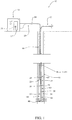
FIG. 1 is a schematic vertical sectional view of an oil-well installation showing an actuator and pump system having an embodiment of the improved sensor data system. -
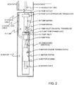
FIG. 2 is a schematic of the actuator and pump system shown inFIG. 1 . -
FIG. 3 is a schematic of the sensor data system shown inFIG. 2 . - At the outset, it should be clearly understood that like reference numerals are intended to identify the same structural elements, portions or surfaces consistently throughout the several drawing figures, as such elements, portions or surfaces may be further described or explained by the entire written specification, of which this detailed description is an integral part. Unless otherwise indicated, the drawings are intended to be read (e.g., crosshatching, arrangement of parts, proportion, degree, etc.) together with the specification, and are to be considered a portion of the entire written description of this invention. As used in the following description, the terms "horizontal", "vertical", "left", "right", "up" and "down", as well as adjectival and adverbial derivatives thereof (e.g., "horizontally", "rightwardly", "upwardly", etc.), simply refer to the orientation of the illustrated structure as the particular drawing figure faces the reader. Similarly, the terms "inwardly" and "outwardly" generally refer to the orientation of a surface relative to its axis of elongation, or axis of rotation, as appropriate.
- Referring now to the drawings, and more particularly to
FIG. 1 , an oil well pump and linear magnetic motor system is provided, a first embodiment of which is generally indicated at 15. As shown, a well hole extends from the surface level to a point below ground. The well hole is lined withcasing 16 to form well bore 18 that includes perforations providing fluid communication between well bore 18 and a hydrocarbon-bearing formation there around.Pump 19 and linear actuator ormotor 20 are disposed at the bottom of well bore 18 and are provided to artificially lift production fluid from well bore 18 throughtubing string 17 to a collection point at the surface. - More specifically, production fluid migrates from the subsurface formation through perforations in
casing 16 and collects in well bore 18.Pump 19 generally comprisescylindrical housing 69 and inner reciprocatingpiston 70.Linear actuator 20 is disposed belowpump 19 in wellbore 18.Linear actuator 20 includesstator 21 andshaft 22, which is connected topiston 70 by actuator rod 64.Linear actuator 20 is powered byelectric cable 24 extending from a motor driver incontroller cabinet 50 at the surface to the bottom of well bore 18. The power supply generates a magnetic field within coils ofstator 21, which in turn imparts an oscillating force onmagnetic shaft 22 and actuator rod 64.Shaft 22 and actuator rod 64 are thereby translated in an up and down or linear fashion withinwell bore 18, which thus imparts linear movement to pumppiston 70. This enablespiston 70 ofpump 19 to reciprocate vertically, thereby enabling fluids to be lifted with each stroke ofpiston 70 towards the surface of well 18.Pump inlet 51 is disposed at the bottom end ofpump housing 69 andpump outlet 52 is disposed at the top end ofpiston 70.Pump 19 forces a first volume of fluid upward withinproduction tubing 17 during an upstroke ofpiston 70 inpump housing 69 and a second volume of fluid upward withinpump housing 69 during a downstroke ofpiston 70 inpump housing 69. - In this embodiment,
actuator 20 is a three-phase permanent magnet linear DC electric motor havingstationary stator 21 and slidingshaft 22. Motor 20 receives power from three-phase power line 24 frommotor driver 50. With references toFIGS. 2 and3 ,linear actuator 20 generally compriseshousing 54,stator 21,shaft 23 and actuator rod 64.Stator 21 andshaft 23 are disposed incylindrical housing 54.Stator 21 does not move axially relative tohousing 54. - As shown in
FIGS. 3 and 4, linearmagnetic motor 20 generally includesstator 21 andshaft 23.Stator 21 is a generally hollow cylindrical member elongated about axis x-x and having innercylindrical passage 22. Shaft 23 is a generally hollow cylindrical member coincident withstator 21 and moves linearly along axis x-x throughpassage 22 relative tostator 21. Movement along axis x-x is referred to herein as movement in the axial direction. - Down-
hole pump 19 includes a standing valve, a traveling valve, piston orplunger 70,inlet 51, andoutlet 52. Aspiston 70 ofpump 19 is forced up and down bymotor 20, oil and other fluid is drawn intoinlet 51, and pushed up out ofoutlet 52.Outlet 52 is coupled toproduction tubing 17 leading to the surface of the oil well. - As shown in
FIGS. 2 and3 , coupled tomotor 20 isdata processing system 36.Data processing system 36 communicates with multiple downhole sensors configured to sense different operating parameters ofmotor 20 andpump 19. As shown inFIGS. 2-3 , such sensors include pumpoutlet pressure transducer 30, pump inlet pressure transducer 31, pump inlet temperature transducer 32,motor stator thermocouple 33, attitude or inclination andvibration sensor 35 and motor shaftposition sensor system 34. Such signals and commands are communicated bysignal cable 23, which extends fromdata processing system 36 onactuator 20 tocontroller cabinet 50 at the surface ofwell 18. -
Position sensors 34 are Hall Effect Devices (HEDs) configured to sense the position and speed oflinear motor shaft 23 relative tostator 21. As shown,sensors 34 are positioned withindata processing system 36 at spaced axial locations proximate toshaft 22. As discussed below,sensors 34 are inputs to a synchronous serial interface (SSI) encoder for sensing the position of the linear motor shaft. -
Sensor 33 is a temperature sensor for monitoring the temperature ofmotor 20. In this embodiment,sensor 33 comprises a K-type (chromel/alumel) thermocouple positioned between motor windings insteel stator 21.Thermocouple 33 is connected to thermocoupleelectrical interface 45, which outputs digital motor temperature data. In this embodiment,interface 45 is a cold-junction compensated thermocouple-to-digital converter. -
Sensor 35 is a microelectromechanical system (MEMS) that provides angular inclination digital data and vibration digital data. Thus, the angle at whichmotor 20 is mounted may be measured byinclinometer 35. -
Sensor 30 is a pressure transducer that provides pressure readings atoutlet 52. Sensor 31 is a pressure transducer that provides pressure readings atinlet 51. Pressure sensor 31 provides oil or fluid pressure atinlet 51 which may be used to determine the depth of oil remaining in the oil well. Sensor 32 is a temperature transducer that provides temperature readings atpump inlet 51. The outputs fromtransducers 30, 31 and 32 are received bysingle transducer interface 47 having analog-to-digital converter 43 andmultiplexer 42. Thus,transducer interface 47 outputs a serial digital signal.System 15 may contain other and/or alternate sensors for monitoring pump operation, motor operation, and/or deep oil well conditions. The data interfaces may be implemented using alternative protocols for either analog or digital signal transfer. - As shown in
FIG. 3 , downholedata processing system 36 generally comprises digitalsignal processor unit 40,differential signal driver 41,transducer interface 47,thermocouple interface 45,MEMS sensor 35 andshaft position sensor 34. - In this embodiment,
signal processor unit 40 is a digital signal processor (DSP) chip orCPU having multiplexor 44.Processor 40 may include data sampling and storage mechanisms for receiving and storing sensory data and may include data storage for storing operational parameters as well as sensory data logs. In particular, in thisembodiment processor 40 is a single chip embedded microcontroller incorporating a 32 bit DSP processing unit along with memory, oscillator, clock, watchdog and I/O in a 100 pin surface mount package. It incorporates 16 channel, 12 bit A/D converter 43 that interfaces with the analog sensor data inputs as well as digital inputs to accept the digital sensor data. The digital signal processor also hasserial output 48 to directly interface with SSIserial bus drivers 41 for exchange of data withsurface controller 50.Processor 40 accepts the sensor data inputs from the various system sensors, reformats the data in the SSI format and transmits the data with the appropriate timing via the SSI bus to surfacecontroller 50. The DSP also monitors the encoder data integrity, power supplies and a separate motor temperature switch and sets fault bits in the SSI data words if the parameters fall outside of acceptable levels. The DSP also continuously monitors the states of the HED devices sensing the motor shaft and through DSP algorithms continually calculates and updates the motor shaft position. -
Processor 40 communicates withthermocouple 33 viathermocouple interface 45, communicates withoutlet pressure transducer 30, inlet pressure transducer 31 and inlet temperature transducer 32 viatransducer interface 47, communicates directly withshaft position sensors 34, and communicates directly withMEMS sensor 35. As shown, analog signals fromoutlet pressure transducer 30, inlet pressure transducer 31 and inlet temperature transducer 32 are converted byinterface 47 into digital signals and multiplexed into a single line. Digital signals fromMEMS 35 are communicated toprocessor 40. In addition, signals fromshaft position sensors 34 are provided toprocessor 40.Processor 40 is configured to receive such data inputs and to provide a serialSSI output signal 48 todifferential signal driver 41. Data is transmitted by synchronizing the transmission at the receiving and sending ends using a common clock signal fromclock 28 located incabinet 50 at the surface of well bore 18. -
Differential signal driver 41 transmits such data electrically via two complementary signals sent on pairedwires 25 and 26 ofcommunication cable 23 toreceiver 27 incabinet 50 above ground. Differential signaling improves the resistance to electromagnetic interference, making it a reliable communication channel over long transmission lengths and harsh external environments. At the surface end ofcable 23,receiver 27 reads the difference between the two signals. In this embodiment, high voltage differential signals are employed. - Thus, the encoder output signal is converted to a digital data word for transmission over a differential serial data bus.
SSI encoder system 36 embeds position data in a digital data word for transmission tocontroller 50. This allows for additional data such as sensor 30-33 and 35 outputs to be embedded and transmitted over to the digital bus in addition to HED derived motor position data fromposition sensor 34. The digital word provides the bandwidth required for operation ofmotor 20 at desired speeds whiledifferential signal driver 41 maintains signal integrity and noise immunity over long transmission distances from the bottom of well bore 18 to the surface andcontroller 50. Additional data fromsensors downhole motor 20 and pump 19, an integrated subsurface communication system is provided. - While the presently preferred form of the system has been shown and described, and several modifications thereof discussed, persons skilled in this art will readily appreciate that various additional changes and modifications may be made without departing from the scope of the invention, as defined and differentiated by the following claims.
Claims (8)
- An oil well installation (15), comprising:tubing (17) arranged in a well (18) and forming a flow channel to a surface level for fluids originating from below said surface level;a pump (19) disposed in said well;a linear actuator (20) disposed in said well and configured to actuate said pump;a cable (24) supplying electric power from said surface level to said linear actuator;a surface controller (50) connected with said linear actuator and configured to control said linear actuator;multiple down hole sensors (30, 31, 32, 33, 34 and 35) configured to sense multiple different operating parameters of said linear actuator and/or said pump;a down hole signal processor (40) communicating with said sensors and configured to receive sensor data from said sensors and to output serial data;a communication cable (23) between said signal processor and said surface controller, said communication cable having at least two paired transmission lines (25, 26):characterised in that the oil well installation (15) further comprisesa down hole differential signal driver (41) configured to receive said serial data and to output data signals to said paired transmission lines; anda surface receiver (27) connected to said communication cable and configured to receive said signals from said differential signal driver via said paired transmission lines.
- The oil well installation set forth in claim 1, wherein said multiple sensors are selected from a group consisting of a temperature sensor (32, 33), a position sensor (34), a vibration sensor (35), an inclination sensor (35) and a pressure sensor (30, 31).
- The oil well installation set forth in claim 2, wherein said multiple sensors are selected from a group consisting of a motor stator thermocouple (33), a pump inlet temperature transducer (32), a pump inlet pressure transducer (31), a pump outlet pressure transducer (30), and a synchronous serial interface encoder (34) configured to sense position of a shaft (22) of said actuator.
- The oil well installation set forth in claim 1, wherein said linear actuator comprises a brushless permanent magnet motor and said sensors comprise a motor position encoder (34) configured to sense position of a shaft (22) of said actuator and an operating sensor selected from a group consisting of a temperature sensor (32, 33), a pressure sensor (30, 31), a vibration sensor (35) and an inclination sensor (35), and wherein said serial data comprises position data from said encoder and operating data from said operating sensor.
- The oil well installation set forth in claim 1, wherein said surface controller comprises a clock (28) communicating with said signal processor and said serial data from said signal processor comprises a synchronous serial data output.
- The oil well installation set forth in claim 1, and further comprising an analog to digital converter (43) communicating with at least one of said sensors and a multiplexer (42) configured to receive sensor signals from at least two of said sensors and to output a serial data signal.
- The oil well installation set forth in claim 1, wherein said actuator comprises a stator (21) having an inner opening and a shaft (22) disposed in said opening and configured and arranged to reciprocate linearly in an axial direction relative to said stator under the effect of a magnetic field generated by said stator.
- The oil well installation set forth in claim 7, wherein said pump comprises an inlet (51), an outlet (52), and a piston (70) coupled to said actuator shaft.
Applications Claiming Priority (2)
| Application Number | Priority Date | Filing Date | Title |
|---|---|---|---|
| US201562189957P | 2015-07-08 | 2015-07-08 | |
| PCT/US2016/040078 WO2017007656A1 (en) | 2015-07-08 | 2016-06-29 | Downhole linear motor and pump sensor data system |
Publications (2)
| Publication Number | Publication Date |
|---|---|
| EP3320176A1 EP3320176A1 (en) | 2018-05-16 |
| EP3320176B1 true EP3320176B1 (en) | 2019-05-01 |
Family
ID=56411922
Family Applications (1)
| Application Number | Title | Priority Date | Filing Date |
|---|---|---|---|
| EP16738953.5A Not-in-force EP3320176B1 (en) | 2015-07-08 | 2016-06-29 | Downhole linear motor and pump sensor data system |
Country Status (6)
| Country | Link |
|---|---|
| US (1) | US20180195373A1 (en) |
| EP (1) | EP3320176B1 (en) |
| CN (1) | CN107923234A (en) |
| AU (1) | AU2016289441A1 (en) |
| CA (1) | CA2991751C (en) |
| WO (1) | WO2017007656A1 (en) |
Cited By (1)
| Publication number | Priority date | Publication date | Assignee | Title |
|---|---|---|---|---|
| WO2021248146A1 (en) * | 2020-06-05 | 2021-12-09 | Baker Hughes Oilfield Operations Llc | Data and power configuration for electrical submersible well pump |
Families Citing this family (7)
| Publication number | Priority date | Publication date | Assignee | Title |
|---|---|---|---|---|
| US10823177B2 (en) * | 2016-08-17 | 2020-11-03 | Baker Hughes, A Ge Company, Llc | Systems and methods for sensing parameters in an ESP using multiple MEMS sensors |
| UA118287C2 (en) * | 2016-12-14 | 2018-12-26 | Хачатуров Дмитро Валерійович | SUBMERSIBLE PUMPING INSTALLATION WITH LINEAR MOTOR AND DUAL PUMP |
| US10774826B2 (en) * | 2017-02-03 | 2020-09-15 | Zilift Holdings, Ltd. | Inline monitoring package for an electric submersible pump system |
| CA2979356C (en) | 2017-09-18 | 2020-03-24 | Jeremy Leonard | Autonomous submersible pump |
| US10934819B2 (en) * | 2017-11-20 | 2021-03-02 | Dmytro KHACHATUROV | Linear electric submersible pump unit |
| CN108626139A (en) * | 2018-07-12 | 2018-10-09 | 杭州乾景科技有限公司 | A kind of submersible electric pump exit parameter measuring apparatus |
| CN110894787B (en) * | 2018-09-12 | 2023-01-31 | 中国石油化工股份有限公司 | Bus driving device for measurement-while-drilling short joint |
Family Cites Families (13)
| Publication number | Priority date | Publication date | Assignee | Title |
|---|---|---|---|---|
| JPS60134651A (en) * | 1983-12-23 | 1985-07-17 | Fujitsu Ltd | Differential signal driver |
| US4839644A (en) * | 1987-06-10 | 1989-06-13 | Schlumberger Technology Corp. | System and method for communicating signals in a cased borehole having tubing |
| US5191326A (en) * | 1991-09-05 | 1993-03-02 | Schlumberger Technology Corporation | Communications protocol for digital telemetry system |
| US5831353A (en) * | 1994-10-17 | 1998-11-03 | Bolding; Vance E. | Modular linear motor and method of constructing and using same |
| WO1996024745A2 (en) * | 1995-02-09 | 1996-08-15 | Baker Hughes Incorporated | Computer controlled downhole tools for production well control |
| US6012015A (en) * | 1995-02-09 | 2000-01-04 | Baker Hughes Incorporated | Control model for production wells |
| US7207396B2 (en) * | 2002-12-10 | 2007-04-24 | Intelliserv, Inc. | Method and apparatus of assessing down-hole drilling conditions |
| US8528395B2 (en) * | 2004-07-05 | 2013-09-10 | Shell Oil Company | Monitoring fluid pressure in a well and retrievable pressure sensor assembly for use in the method |
| US8092190B2 (en) * | 2007-04-06 | 2012-01-10 | Baker Hughes Incorporated | Systems and methods for reducing pump downtime by determining rotation speed using a variable speed drive |
| US20130197810A1 (en) * | 2012-01-27 | 2013-08-01 | Allan Kayser Haas | Monitoring of drinking water aquifers during possible contamination operations |
| US20150308244A1 (en) * | 2012-11-26 | 2015-10-29 | Moog Inc. | Methods and system for controlling a linear motor for a deep well oil pump |
| RU2616023C1 (en) * | 2013-12-26 | 2017-04-12 | Хан'С Лазер Текнолоджи Индастри Груп Ко., Лтд | System for oil production with linear electric motor submerged into oil |
| US9664011B2 (en) * | 2014-05-27 | 2017-05-30 | Baker Hughes Incorporated | High-speed camera to monitor surface drilling dynamics and provide optical data link for receiving downhole data |
-
2016
- 2016-06-29 WO PCT/US2016/040078 patent/WO2017007656A1/en active Application Filing
- 2016-06-29 CN CN201680047914.0A patent/CN107923234A/en active Pending
- 2016-06-29 US US15/741,958 patent/US20180195373A1/en not_active Abandoned
- 2016-06-29 CA CA2991751A patent/CA2991751C/en not_active Expired - Fee Related
- 2016-06-29 EP EP16738953.5A patent/EP3320176B1/en not_active Not-in-force
- 2016-06-29 AU AU2016289441A patent/AU2016289441A1/en not_active Abandoned
Non-Patent Citations (1)
| Title |
|---|
| None * |
Cited By (2)
| Publication number | Priority date | Publication date | Assignee | Title |
|---|---|---|---|---|
| WO2021248146A1 (en) * | 2020-06-05 | 2021-12-09 | Baker Hughes Oilfield Operations Llc | Data and power configuration for electrical submersible well pump |
| US11674518B2 (en) | 2020-06-05 | 2023-06-13 | Baker Hughes Oilfield Operations Llc | Data and power configuration for electrical submersible well pump |
Also Published As
| Publication number | Publication date |
|---|---|
| CA2991751A1 (en) | 2017-01-12 |
| EP3320176A1 (en) | 2018-05-16 |
| US20180195373A1 (en) | 2018-07-12 |
| AU2016289441A1 (en) | 2018-02-01 |
| CA2991751C (en) | 2020-07-28 |
| CN107923234A (en) | 2018-04-17 |
| WO2017007656A1 (en) | 2017-01-12 |
Similar Documents
| Publication | Publication Date | Title |
|---|---|---|
| EP3320176B1 (en) | Downhole linear motor and pump sensor data system | |
| RU2606196C2 (en) | Pump and pump section | |
| US6695052B2 (en) | Technique for sensing flow related parameters when using an electric submersible pumping system to produce a desired fluid | |
| EP2735699B1 (en) | Method and apparatus for sensing in wellbores | |
| AU2014369986B2 (en) | Downhole motor driven reciprocating well pump | |
| CN204436373U (en) | A kind of underground high-power is powered mud signal generator | |
| CA2848192A1 (en) | Electrical submersible pump flow meter | |
| US9726166B2 (en) | Magnetic rotational to linear actuator for well pumps | |
| US10280720B2 (en) | Submersible reciprocating oil well pump unit | |
| EP3308022B1 (en) | Dual completion linear rod pump | |
| EP3170968B1 (en) | Well pumping system and method | |
| RU2622574C2 (en) | Downhole drilling motor and method of use | |
| US10094212B2 (en) | Data communications system | |
| EP4015764A1 (en) | Pumpjack having linear alternator | |
| CN102536217A (en) | Positive pulse device for slurry under shaft | |
| WO2014044334A9 (en) | Improved pump for lifting fluid from a wellbore | |
| CA2746081A1 (en) | Contactless position detection switch | |
| CN107548427A (en) | Drilling tool with nearly drill bit electronic installation | |
| CA3098027A1 (en) | Hydraulically actuated double-acting positive displacement pump system for producing fluids from a deviated wellbore | |
| WO2021247047A1 (en) | Downhole linear pump system | |
| RU2801629C1 (en) | Plunger unit with linear motor (variants) | |
| UA115401C2 (en) | Borehole Pump Installation | |
| CN113123950A (en) | Submersible electric plunger pump |
Legal Events
| Date | Code | Title | Description |
|---|---|---|---|
| STAA | Information on the status of an ep patent application or granted ep patent |
Free format text: STATUS: THE INTERNATIONAL PUBLICATION HAS BEEN MADE |
|
| PUAI | Public reference made under article 153(3) epc to a published international application that has entered the european phase |
Free format text: ORIGINAL CODE: 0009012 |
|
| STAA | Information on the status of an ep patent application or granted ep patent |
Free format text: STATUS: REQUEST FOR EXAMINATION WAS MADE |
|
| 17P | Request for examination filed |
Effective date: 20180111 |
|
| AK | Designated contracting states |
Kind code of ref document: A1 Designated state(s): AL AT BE BG CH CY CZ DE DK EE ES FI FR GB GR HR HU IE IS IT LI LT LU LV MC MK MT NL NO PL PT RO RS SE SI SK SM TR |
|
| AX | Request for extension of the european patent |
Extension state: BA ME |
|
| DAV | Request for validation of the european patent (deleted) | ||
| DAX | Request for extension of the european patent (deleted) | ||
| GRAP | Despatch of communication of intention to grant a patent |
Free format text: ORIGINAL CODE: EPIDOSNIGR1 |
|
| STAA | Information on the status of an ep patent application or granted ep patent |
Free format text: STATUS: GRANT OF PATENT IS INTENDED |
|
| INTG | Intention to grant announced |
Effective date: 20181105 |
|
| GRAS | Grant fee paid |
Free format text: ORIGINAL CODE: EPIDOSNIGR3 |
|
| GRAA | (expected) grant |
Free format text: ORIGINAL CODE: 0009210 |
|
| STAA | Information on the status of an ep patent application or granted ep patent |
Free format text: STATUS: THE PATENT HAS BEEN GRANTED |
|
| AK | Designated contracting states |
Kind code of ref document: B1 Designated state(s): AL AT BE BG CH CY CZ DE DK EE ES FI FR GB GR HR HU IE IS IT LI LT LU LV MC MK MT NL NO PL PT RO RS SE SI SK SM TR |
|
| REG | Reference to a national code |
Ref country code: GB Ref legal event code: FG4D |
|
| REG | Reference to a national code |
Ref country code: CH Ref legal event code: EP Ref country code: AT Ref legal event code: REF Ref document number: 1127132 Country of ref document: AT Kind code of ref document: T Effective date: 20190515 |
|
| REG | Reference to a national code |
Ref country code: DE Ref legal event code: R096 Ref document number: 602016013289 Country of ref document: DE |
|
| REG | Reference to a national code |
Ref country code: IE Ref legal event code: FG4D |
|
| REG | Reference to a national code |
Ref country code: NL Ref legal event code: MP Effective date: 20190501 |
|
| REG | Reference to a national code |
Ref country code: LT Ref legal event code: MG4D |
|
| PG25 | Lapsed in a contracting state [announced via postgrant information from national office to epo] |
Ref country code: NL Free format text: LAPSE BECAUSE OF FAILURE TO SUBMIT A TRANSLATION OF THE DESCRIPTION OR TO PAY THE FEE WITHIN THE PRESCRIBED TIME-LIMIT Effective date: 20190501 Ref country code: SE Free format text: LAPSE BECAUSE OF FAILURE TO SUBMIT A TRANSLATION OF THE DESCRIPTION OR TO PAY THE FEE WITHIN THE PRESCRIBED TIME-LIMIT Effective date: 20190501 Ref country code: HR Free format text: LAPSE BECAUSE OF FAILURE TO SUBMIT A TRANSLATION OF THE DESCRIPTION OR TO PAY THE FEE WITHIN THE PRESCRIBED TIME-LIMIT Effective date: 20190501 Ref country code: PT Free format text: LAPSE BECAUSE OF FAILURE TO SUBMIT A TRANSLATION OF THE DESCRIPTION OR TO PAY THE FEE WITHIN THE PRESCRIBED TIME-LIMIT Effective date: 20190901 Ref country code: AL Free format text: LAPSE BECAUSE OF FAILURE TO SUBMIT A TRANSLATION OF THE DESCRIPTION OR TO PAY THE FEE WITHIN THE PRESCRIBED TIME-LIMIT Effective date: 20190501 Ref country code: FI Free format text: LAPSE BECAUSE OF FAILURE TO SUBMIT A TRANSLATION OF THE DESCRIPTION OR TO PAY THE FEE WITHIN THE PRESCRIBED TIME-LIMIT Effective date: 20190501 Ref country code: NO Free format text: LAPSE BECAUSE OF FAILURE TO SUBMIT A TRANSLATION OF THE DESCRIPTION OR TO PAY THE FEE WITHIN THE PRESCRIBED TIME-LIMIT Effective date: 20190801 Ref country code: ES Free format text: LAPSE BECAUSE OF FAILURE TO SUBMIT A TRANSLATION OF THE DESCRIPTION OR TO PAY THE FEE WITHIN THE PRESCRIBED TIME-LIMIT Effective date: 20190501 Ref country code: LT Free format text: LAPSE BECAUSE OF FAILURE TO SUBMIT A TRANSLATION OF THE DESCRIPTION OR TO PAY THE FEE WITHIN THE PRESCRIBED TIME-LIMIT Effective date: 20190501 |
|
| PG25 | Lapsed in a contracting state [announced via postgrant information from national office to epo] |
Ref country code: GR Free format text: LAPSE BECAUSE OF FAILURE TO SUBMIT A TRANSLATION OF THE DESCRIPTION OR TO PAY THE FEE WITHIN THE PRESCRIBED TIME-LIMIT Effective date: 20190802 Ref country code: BG Free format text: LAPSE BECAUSE OF FAILURE TO SUBMIT A TRANSLATION OF THE DESCRIPTION OR TO PAY THE FEE WITHIN THE PRESCRIBED TIME-LIMIT Effective date: 20190801 Ref country code: RS Free format text: LAPSE BECAUSE OF FAILURE TO SUBMIT A TRANSLATION OF THE DESCRIPTION OR TO PAY THE FEE WITHIN THE PRESCRIBED TIME-LIMIT Effective date: 20190501 Ref country code: LV Free format text: LAPSE BECAUSE OF FAILURE TO SUBMIT A TRANSLATION OF THE DESCRIPTION OR TO PAY THE FEE WITHIN THE PRESCRIBED TIME-LIMIT Effective date: 20190501 |
|
| REG | Reference to a national code |
Ref country code: AT Ref legal event code: MK05 Ref document number: 1127132 Country of ref document: AT Kind code of ref document: T Effective date: 20190501 |
|
| PG25 | Lapsed in a contracting state [announced via postgrant information from national office to epo] |
Ref country code: IS Free format text: LAPSE BECAUSE OF FAILURE TO SUBMIT A TRANSLATION OF THE DESCRIPTION OR TO PAY THE FEE WITHIN THE PRESCRIBED TIME-LIMIT Effective date: 20190901 |
|
| REG | Reference to a national code |
Ref country code: DE Ref legal event code: R119 Ref document number: 602016013289 Country of ref document: DE |
|
| PG25 | Lapsed in a contracting state [announced via postgrant information from national office to epo] |
Ref country code: DK Free format text: LAPSE BECAUSE OF FAILURE TO SUBMIT A TRANSLATION OF THE DESCRIPTION OR TO PAY THE FEE WITHIN THE PRESCRIBED TIME-LIMIT Effective date: 20190501 Ref country code: EE Free format text: LAPSE BECAUSE OF FAILURE TO SUBMIT A TRANSLATION OF THE DESCRIPTION OR TO PAY THE FEE WITHIN THE PRESCRIBED TIME-LIMIT Effective date: 20190501 Ref country code: AT Free format text: LAPSE BECAUSE OF FAILURE TO SUBMIT A TRANSLATION OF THE DESCRIPTION OR TO PAY THE FEE WITHIN THE PRESCRIBED TIME-LIMIT Effective date: 20190501 Ref country code: CZ Free format text: LAPSE BECAUSE OF FAILURE TO SUBMIT A TRANSLATION OF THE DESCRIPTION OR TO PAY THE FEE WITHIN THE PRESCRIBED TIME-LIMIT Effective date: 20190501 Ref country code: RO Free format text: LAPSE BECAUSE OF FAILURE TO SUBMIT A TRANSLATION OF THE DESCRIPTION OR TO PAY THE FEE WITHIN THE PRESCRIBED TIME-LIMIT Effective date: 20190501 Ref country code: MC Free format text: LAPSE BECAUSE OF FAILURE TO SUBMIT A TRANSLATION OF THE DESCRIPTION OR TO PAY THE FEE WITHIN THE PRESCRIBED TIME-LIMIT Effective date: 20190501 Ref country code: SK Free format text: LAPSE BECAUSE OF FAILURE TO SUBMIT A TRANSLATION OF THE DESCRIPTION OR TO PAY THE FEE WITHIN THE PRESCRIBED TIME-LIMIT Effective date: 20190501 |
|
| REG | Reference to a national code |
Ref country code: CH Ref legal event code: PL |
|
| PG25 | Lapsed in a contracting state [announced via postgrant information from national office to epo] |
Ref country code: SM Free format text: LAPSE BECAUSE OF FAILURE TO SUBMIT A TRANSLATION OF THE DESCRIPTION OR TO PAY THE FEE WITHIN THE PRESCRIBED TIME-LIMIT Effective date: 20190501 Ref country code: IT Free format text: LAPSE BECAUSE OF FAILURE TO SUBMIT A TRANSLATION OF THE DESCRIPTION OR TO PAY THE FEE WITHIN THE PRESCRIBED TIME-LIMIT Effective date: 20190501 |
|
| PLBE | No opposition filed within time limit |
Free format text: ORIGINAL CODE: 0009261 |
|
| STAA | Information on the status of an ep patent application or granted ep patent |
Free format text: STATUS: NO OPPOSITION FILED WITHIN TIME LIMIT |
|
| REG | Reference to a national code |
Ref country code: BE Ref legal event code: MM Effective date: 20190630 |
|
| PG25 | Lapsed in a contracting state [announced via postgrant information from national office to epo] |
Ref country code: TR Free format text: LAPSE BECAUSE OF FAILURE TO SUBMIT A TRANSLATION OF THE DESCRIPTION OR TO PAY THE FEE WITHIN THE PRESCRIBED TIME-LIMIT Effective date: 20190501 |
|
| 26N | No opposition filed |
Effective date: 20200204 |
|
| PG25 | Lapsed in a contracting state [announced via postgrant information from national office to epo] |
Ref country code: PL Free format text: LAPSE BECAUSE OF FAILURE TO SUBMIT A TRANSLATION OF THE DESCRIPTION OR TO PAY THE FEE WITHIN THE PRESCRIBED TIME-LIMIT Effective date: 20190501 Ref country code: DE Free format text: LAPSE BECAUSE OF NON-PAYMENT OF DUE FEES Effective date: 20200101 Ref country code: IE Free format text: LAPSE BECAUSE OF NON-PAYMENT OF DUE FEES Effective date: 20190629 |
|
| PG25 | Lapsed in a contracting state [announced via postgrant information from national office to epo] |
Ref country code: CH Free format text: LAPSE BECAUSE OF NON-PAYMENT OF DUE FEES Effective date: 20190630 Ref country code: SI Free format text: LAPSE BECAUSE OF FAILURE TO SUBMIT A TRANSLATION OF THE DESCRIPTION OR TO PAY THE FEE WITHIN THE PRESCRIBED TIME-LIMIT Effective date: 20190501 Ref country code: LI Free format text: LAPSE BECAUSE OF NON-PAYMENT OF DUE FEES Effective date: 20190630 Ref country code: LU Free format text: LAPSE BECAUSE OF NON-PAYMENT OF DUE FEES Effective date: 20190629 Ref country code: BE Free format text: LAPSE BECAUSE OF NON-PAYMENT OF DUE FEES Effective date: 20190630 |
|
| PG25 | Lapsed in a contracting state [announced via postgrant information from national office to epo] |
Ref country code: FR Free format text: LAPSE BECAUSE OF NON-PAYMENT OF DUE FEES Effective date: 20190701 |
|
| PGFP | Annual fee paid to national office [announced via postgrant information from national office to epo] |
Ref country code: GB Payment date: 20200629 Year of fee payment: 5 |
|
| PG25 | Lapsed in a contracting state [announced via postgrant information from national office to epo] |
Ref country code: CY Free format text: LAPSE BECAUSE OF FAILURE TO SUBMIT A TRANSLATION OF THE DESCRIPTION OR TO PAY THE FEE WITHIN THE PRESCRIBED TIME-LIMIT Effective date: 20190501 |
|
| PG25 | Lapsed in a contracting state [announced via postgrant information from national office to epo] |
Ref country code: MT Free format text: LAPSE BECAUSE OF FAILURE TO SUBMIT A TRANSLATION OF THE DESCRIPTION OR TO PAY THE FEE WITHIN THE PRESCRIBED TIME-LIMIT Effective date: 20190501 Ref country code: HU Free format text: LAPSE BECAUSE OF FAILURE TO SUBMIT A TRANSLATION OF THE DESCRIPTION OR TO PAY THE FEE WITHIN THE PRESCRIBED TIME-LIMIT; INVALID AB INITIO Effective date: 20160629 |
|
| GBPC | Gb: european patent ceased through non-payment of renewal fee |
Effective date: 20210629 |
|
| PG25 | Lapsed in a contracting state [announced via postgrant information from national office to epo] |
Ref country code: GB Free format text: LAPSE BECAUSE OF NON-PAYMENT OF DUE FEES Effective date: 20210629 |
|
| PG25 | Lapsed in a contracting state [announced via postgrant information from national office to epo] |
Ref country code: MK Free format text: LAPSE BECAUSE OF FAILURE TO SUBMIT A TRANSLATION OF THE DESCRIPTION OR TO PAY THE FEE WITHIN THE PRESCRIBED TIME-LIMIT Effective date: 20190501 |