EP3319647B1 - Air purifier and atmosphere scenting - Google Patents
Air purifier and atmosphere scenting Download PDFInfo
- Publication number
- EP3319647B1 EP3319647B1 EP17720726.3A EP17720726A EP3319647B1 EP 3319647 B1 EP3319647 B1 EP 3319647B1 EP 17720726 A EP17720726 A EP 17720726A EP 3319647 B1 EP3319647 B1 EP 3319647B1
- Authority
- EP
- European Patent Office
- Prior art keywords
- scent
- air
- room
- processor
- purification system
- Prior art date
- Legal status (The legal status is an assumption and is not a legal conclusion. Google has not performed a legal analysis and makes no representation as to the accuracy of the status listed.)
- Active
Links
Images



Classifications
-
- A—HUMAN NECESSITIES
- A61—MEDICAL OR VETERINARY SCIENCE; HYGIENE
- A61L—METHODS OR APPARATUS FOR STERILISING MATERIALS OR OBJECTS IN GENERAL; DISINFECTION, STERILISATION OR DEODORISATION OF AIR; CHEMICAL ASPECTS OF BANDAGES, DRESSINGS, ABSORBENT PADS OR SURGICAL ARTICLES; MATERIALS FOR BANDAGES, DRESSINGS, ABSORBENT PADS OR SURGICAL ARTICLES
- A61L9/00—Disinfection, sterilisation or deodorisation of air
- A61L9/015—Disinfection, sterilisation or deodorisation of air using gaseous or vaporous substances, e.g. ozone
- A61L9/02—Disinfection, sterilisation or deodorisation of air using gaseous or vaporous substances, e.g. ozone using substances evaporated in the air by heating or combustion
- A61L9/03—Apparatus therefor
- A61L9/037—Apparatus therefor comprising a wick
-
- A—HUMAN NECESSITIES
- A61—MEDICAL OR VETERINARY SCIENCE; HYGIENE
- A61L—METHODS OR APPARATUS FOR STERILISING MATERIALS OR OBJECTS IN GENERAL; DISINFECTION, STERILISATION OR DEODORISATION OF AIR; CHEMICAL ASPECTS OF BANDAGES, DRESSINGS, ABSORBENT PADS OR SURGICAL ARTICLES; MATERIALS FOR BANDAGES, DRESSINGS, ABSORBENT PADS OR SURGICAL ARTICLES
- A61L9/00—Disinfection, sterilisation or deodorisation of air
- A61L9/015—Disinfection, sterilisation or deodorisation of air using gaseous or vaporous substances, e.g. ozone
- A61L9/02—Disinfection, sterilisation or deodorisation of air using gaseous or vaporous substances, e.g. ozone using substances evaporated in the air by heating or combustion
- A61L9/03—Apparatus therefor
-
- A—HUMAN NECESSITIES
- A61—MEDICAL OR VETERINARY SCIENCE; HYGIENE
- A61L—METHODS OR APPARATUS FOR STERILISING MATERIALS OR OBJECTS IN GENERAL; DISINFECTION, STERILISATION OR DEODORISATION OF AIR; CHEMICAL ASPECTS OF BANDAGES, DRESSINGS, ABSORBENT PADS OR SURGICAL ARTICLES; MATERIALS FOR BANDAGES, DRESSINGS, ABSORBENT PADS OR SURGICAL ARTICLES
- A61L9/00—Disinfection, sterilisation or deodorisation of air
- A61L9/015—Disinfection, sterilisation or deodorisation of air using gaseous or vaporous substances, e.g. ozone
- A61L9/02—Disinfection, sterilisation or deodorisation of air using gaseous or vaporous substances, e.g. ozone using substances evaporated in the air by heating or combustion
- A61L9/03—Apparatus therefor
- A61L9/032—Apparatus therefor comprising a fan
-
- A—HUMAN NECESSITIES
- A61—MEDICAL OR VETERINARY SCIENCE; HYGIENE
- A61L—METHODS OR APPARATUS FOR STERILISING MATERIALS OR OBJECTS IN GENERAL; DISINFECTION, STERILISATION OR DEODORISATION OF AIR; CHEMICAL ASPECTS OF BANDAGES, DRESSINGS, ABSORBENT PADS OR SURGICAL ARTICLES; MATERIALS FOR BANDAGES, DRESSINGS, ABSORBENT PADS OR SURGICAL ARTICLES
- A61L9/00—Disinfection, sterilisation or deodorisation of air
- A61L9/015—Disinfection, sterilisation or deodorisation of air using gaseous or vaporous substances, e.g. ozone
- A61L9/02—Disinfection, sterilisation or deodorisation of air using gaseous or vaporous substances, e.g. ozone using substances evaporated in the air by heating or combustion
- A61L9/03—Apparatus therefor
- A61L9/035—Apparatus therefor emanating multiple odours
-
- B—PERFORMING OPERATIONS; TRANSPORTING
- B01—PHYSICAL OR CHEMICAL PROCESSES OR APPARATUS IN GENERAL
- B01D—SEPARATION
- B01D53/00—Separation of gases or vapours; Recovering vapours of volatile solvents from gases; Chemical or biological purification of waste gases, e.g. engine exhaust gases, smoke, fumes, flue gases, aerosols
- B01D53/02—Separation of gases or vapours; Recovering vapours of volatile solvents from gases; Chemical or biological purification of waste gases, e.g. engine exhaust gases, smoke, fumes, flue gases, aerosols by adsorption, e.g. preparative gas chromatography
- B01D53/04—Separation of gases or vapours; Recovering vapours of volatile solvents from gases; Chemical or biological purification of waste gases, e.g. engine exhaust gases, smoke, fumes, flue gases, aerosols by adsorption, e.g. preparative gas chromatography with stationary adsorbents
- B01D53/0407—Constructional details of adsorbing systems
-
- B—PERFORMING OPERATIONS; TRANSPORTING
- B01—PHYSICAL OR CHEMICAL PROCESSES OR APPARATUS IN GENERAL
- B01D—SEPARATION
- B01D53/00—Separation of gases or vapours; Recovering vapours of volatile solvents from gases; Chemical or biological purification of waste gases, e.g. engine exhaust gases, smoke, fumes, flue gases, aerosols
- B01D53/02—Separation of gases or vapours; Recovering vapours of volatile solvents from gases; Chemical or biological purification of waste gases, e.g. engine exhaust gases, smoke, fumes, flue gases, aerosols by adsorption, e.g. preparative gas chromatography
- B01D53/04—Separation of gases or vapours; Recovering vapours of volatile solvents from gases; Chemical or biological purification of waste gases, e.g. engine exhaust gases, smoke, fumes, flue gases, aerosols by adsorption, e.g. preparative gas chromatography with stationary adsorbents
- B01D53/0454—Controlling adsorption
-
- F—MECHANICAL ENGINEERING; LIGHTING; HEATING; WEAPONS; BLASTING
- F24—HEATING; RANGES; VENTILATING
- F24F—AIR-CONDITIONING; AIR-HUMIDIFICATION; VENTILATION; USE OF AIR CURRENTS FOR SCREENING
- F24F11/00—Control or safety arrangements
-
- F—MECHANICAL ENGINEERING; LIGHTING; HEATING; WEAPONS; BLASTING
- F24—HEATING; RANGES; VENTILATING
- F24F—AIR-CONDITIONING; AIR-HUMIDIFICATION; VENTILATION; USE OF AIR CURRENTS FOR SCREENING
- F24F11/00—Control or safety arrangements
- F24F11/62—Control or safety arrangements characterised by the type of control or by internal processing, e.g. using fuzzy logic, adaptive control or estimation of values
- F24F11/63—Electronic processing
-
- F—MECHANICAL ENGINEERING; LIGHTING; HEATING; WEAPONS; BLASTING
- F24—HEATING; RANGES; VENTILATING
- F24F—AIR-CONDITIONING; AIR-HUMIDIFICATION; VENTILATION; USE OF AIR CURRENTS FOR SCREENING
- F24F11/00—Control or safety arrangements
- F24F11/62—Control or safety arrangements characterised by the type of control or by internal processing, e.g. using fuzzy logic, adaptive control or estimation of values
- F24F11/63—Electronic processing
- F24F11/64—Electronic processing using pre-stored data
-
- F—MECHANICAL ENGINEERING; LIGHTING; HEATING; WEAPONS; BLASTING
- F24—HEATING; RANGES; VENTILATING
- F24F—AIR-CONDITIONING; AIR-HUMIDIFICATION; VENTILATION; USE OF AIR CURRENTS FOR SCREENING
- F24F11/00—Control or safety arrangements
- F24F11/62—Control or safety arrangements characterised by the type of control or by internal processing, e.g. using fuzzy logic, adaptive control or estimation of values
- F24F11/63—Electronic processing
- F24F11/65—Electronic processing for selecting an operating mode
-
- F—MECHANICAL ENGINEERING; LIGHTING; HEATING; WEAPONS; BLASTING
- F24—HEATING; RANGES; VENTILATING
- F24F—AIR-CONDITIONING; AIR-HUMIDIFICATION; VENTILATION; USE OF AIR CURRENTS FOR SCREENING
- F24F8/00—Treatment, e.g. purification, of air supplied to human living or working spaces otherwise than by heating, cooling, humidifying or drying
- F24F8/50—Treatment, e.g. purification, of air supplied to human living or working spaces otherwise than by heating, cooling, humidifying or drying by odorisation
-
- A—HUMAN NECESSITIES
- A61—MEDICAL OR VETERINARY SCIENCE; HYGIENE
- A61L—METHODS OR APPARATUS FOR STERILISING MATERIALS OR OBJECTS IN GENERAL; DISINFECTION, STERILISATION OR DEODORISATION OF AIR; CHEMICAL ASPECTS OF BANDAGES, DRESSINGS, ABSORBENT PADS OR SURGICAL ARTICLES; MATERIALS FOR BANDAGES, DRESSINGS, ABSORBENT PADS OR SURGICAL ARTICLES
- A61L2209/00—Aspects relating to disinfection, sterilisation or deodorisation of air
- A61L2209/10—Apparatus features
- A61L2209/11—Apparatus for controlling air treatment
- A61L2209/111—Sensor means, e.g. motion, brightness, scent, contaminant sensors
-
- A—HUMAN NECESSITIES
- A61—MEDICAL OR VETERINARY SCIENCE; HYGIENE
- A61L—METHODS OR APPARATUS FOR STERILISING MATERIALS OR OBJECTS IN GENERAL; DISINFECTION, STERILISATION OR DEODORISATION OF AIR; CHEMICAL ASPECTS OF BANDAGES, DRESSINGS, ABSORBENT PADS OR SURGICAL ARTICLES; MATERIALS FOR BANDAGES, DRESSINGS, ABSORBENT PADS OR SURGICAL ARTICLES
- A61L2209/00—Aspects relating to disinfection, sterilisation or deodorisation of air
- A61L2209/10—Apparatus features
- A61L2209/13—Dispensing or storing means for active compounds
-
- A—HUMAN NECESSITIES
- A61—MEDICAL OR VETERINARY SCIENCE; HYGIENE
- A61L—METHODS OR APPARATUS FOR STERILISING MATERIALS OR OBJECTS IN GENERAL; DISINFECTION, STERILISATION OR DEODORISATION OF AIR; CHEMICAL ASPECTS OF BANDAGES, DRESSINGS, ABSORBENT PADS OR SURGICAL ARTICLES; MATERIALS FOR BANDAGES, DRESSINGS, ABSORBENT PADS OR SURGICAL ARTICLES
- A61L2209/00—Aspects relating to disinfection, sterilisation or deodorisation of air
- A61L2209/10—Apparatus features
- A61L2209/13—Dispensing or storing means for active compounds
- A61L2209/133—Replaceable cartridges, refills
-
- A—HUMAN NECESSITIES
- A61—MEDICAL OR VETERINARY SCIENCE; HYGIENE
- A61L—METHODS OR APPARATUS FOR STERILISING MATERIALS OR OBJECTS IN GENERAL; DISINFECTION, STERILISATION OR DEODORISATION OF AIR; CHEMICAL ASPECTS OF BANDAGES, DRESSINGS, ABSORBENT PADS OR SURGICAL ARTICLES; MATERIALS FOR BANDAGES, DRESSINGS, ABSORBENT PADS OR SURGICAL ARTICLES
- A61L2209/00—Aspects relating to disinfection, sterilisation or deodorisation of air
- A61L2209/10—Apparatus features
- A61L2209/14—Filtering means
-
- B—PERFORMING OPERATIONS; TRANSPORTING
- B01—PHYSICAL OR CHEMICAL PROCESSES OR APPARATUS IN GENERAL
- B01D—SEPARATION
- B01D2253/00—Adsorbents used in seperation treatment of gases and vapours
- B01D2253/10—Inorganic adsorbents
- B01D2253/102—Carbon
-
- B—PERFORMING OPERATIONS; TRANSPORTING
- B01—PHYSICAL OR CHEMICAL PROCESSES OR APPARATUS IN GENERAL
- B01D—SEPARATION
- B01D2257/00—Components to be removed
- B01D2257/70—Organic compounds not provided for in groups B01D2257/00 - B01D2257/602
- B01D2257/708—Volatile organic compounds V.O.C.'s
-
- B—PERFORMING OPERATIONS; TRANSPORTING
- B01—PHYSICAL OR CHEMICAL PROCESSES OR APPARATUS IN GENERAL
- B01D—SEPARATION
- B01D2257/00—Components to be removed
- B01D2257/90—Odorous compounds not provided for in groups B01D2257/00 - B01D2257/708
-
- B—PERFORMING OPERATIONS; TRANSPORTING
- B01—PHYSICAL OR CHEMICAL PROCESSES OR APPARATUS IN GENERAL
- B01D—SEPARATION
- B01D2257/00—Components to be removed
- B01D2257/91—Bacteria; Microorganisms
-
- B—PERFORMING OPERATIONS; TRANSPORTING
- B01—PHYSICAL OR CHEMICAL PROCESSES OR APPARATUS IN GENERAL
- B01D—SEPARATION
- B01D2258/00—Sources of waste gases
- B01D2258/06—Polluted air
-
- B—PERFORMING OPERATIONS; TRANSPORTING
- B01—PHYSICAL OR CHEMICAL PROCESSES OR APPARATUS IN GENERAL
- B01D—SEPARATION
- B01D2259/00—Type of treatment
- B01D2259/45—Gas separation or purification devices adapted for specific applications
- B01D2259/4508—Gas separation or purification devices adapted for specific applications for cleaning air in buildings
-
- F—MECHANICAL ENGINEERING; LIGHTING; HEATING; WEAPONS; BLASTING
- F24—HEATING; RANGES; VENTILATING
- F24F—AIR-CONDITIONING; AIR-HUMIDIFICATION; VENTILATION; USE OF AIR CURRENTS FOR SCREENING
- F24F11/00—Control or safety arrangements
- F24F11/30—Control or safety arrangements for purposes related to the operation of the system, e.g. for safety or monitoring
-
- F—MECHANICAL ENGINEERING; LIGHTING; HEATING; WEAPONS; BLASTING
- F24—HEATING; RANGES; VENTILATING
- F24F—AIR-CONDITIONING; AIR-HUMIDIFICATION; VENTILATION; USE OF AIR CURRENTS FOR SCREENING
- F24F2110/00—Control inputs relating to air properties
- F24F2110/50—Air quality properties
-
- Y—GENERAL TAGGING OF NEW TECHNOLOGICAL DEVELOPMENTS; GENERAL TAGGING OF CROSS-SECTIONAL TECHNOLOGIES SPANNING OVER SEVERAL SECTIONS OF THE IPC; TECHNICAL SUBJECTS COVERED BY FORMER USPC CROSS-REFERENCE ART COLLECTIONS [XRACs] AND DIGESTS
- Y02—TECHNOLOGIES OR APPLICATIONS FOR MITIGATION OR ADAPTATION AGAINST CLIMATE CHANGE
- Y02B—CLIMATE CHANGE MITIGATION TECHNOLOGIES RELATED TO BUILDINGS, e.g. HOUSING, HOUSE APPLIANCES OR RELATED END-USER APPLICATIONS
- Y02B30/00—Energy efficient heating, ventilation or air conditioning [HVAC]
- Y02B30/70—Efficient control or regulation technologies, e.g. for control of refrigerant flow, motor or heating
Definitions
- the present invention relates to an air purification system comprising an air purifier apparatus for removing a pollutant from air, a sensor for sensing a concentration of the air pollutant and a scent release apparatus.
- the present invention further relates to a method of generating a scented atmosphere in a room housing an air purification apparatus for removing a pollutant from the air in the room.
- Scent release devices such as air fresheners are commonly used to create a scented atmosphere in a confined space such as a room. This for instance may be done to mask unpleasant smells or simply to generate a pleasant atmosphere within the confined space, such as a flowery smell, a forest-like smell, a sea smell and so on.
- US 2009/0162253 A1 discloses a volatile material diffuser that includes a housing and first and second containers holding first and second volatile materials and having first and second wicks, respectively, in contact with respective volatile materials and extending out of respective containers, wherein the containers are inserted into and detachably attached to the housing.
- the diffuser further includes first and second heaters disposed within the housing adjacent the first and second wicks, respectively, to vaporize the first and second volatile materials, respectively.
- WO2014011063 discloses an air treatment unit for use at e.g. outlets of ventilation ducts in e.g. buildings, equipped with a fragrance dispenser and an air contamination sensor and/or set of air contamination sensors, for sensing contaminants in air flowing through duct or duct airflow, and connected with control unit for controlling air circulation device.
- scent release devices are not without issues. For example, excessive release of the volatile compounds can lead to a perception of an overwhelming scent in the confined space, which often is perceived as unpleasant.
- many of the volatile compounds used to create a scented environment are reactive organic molecules that may react with pollutants in the atmosphere within the confined space to create reaction products that are potentially harmful to the inhabitants of the confined space.
- isoprene can react with hydroxyl radicals or ozone to form harmful compounds such as methyl vinyl ketone and methacrylaldehyde.
- the scent release device may be combined with an air purifier or air conditioner such as for example disclosed in utility model KR 2009/08236U .
- the present invention seeks to provide an air purification system that reduces the risk of the generation of harmful reaction products when releasing a scent into air.
- the present invention further seeks to provide an air purification method that reduces the risk of the generation of harmful reaction products when releasing a scent into air.
- an air purification system comprising an air purifier apparatus for removing a pollutant from air, a sensor for sensing a concentration of the air pollutant and a scent release apparatus responsive to a scent release signal, wherein the air purification system further comprises a processor adapted to monitor the pollutant concentration from sensor data received from the sensor and to generate the scent release signal upon the monitored pollutant concentration falling below a defined threshold.
- the processor thus comprises a monitoring means for monitoring the pollutant concentration, a threshold setting means, and a scent release signal generation means which receives as input the the monitored pollutant concentration and the threshold set by the threshold setting means and generates the scent release signal, wherein the threshold set is a maximum concentration for the air pollutant during which scent may be released.
- the scent release signal may be generated without delay if the pollutant concentration is already sufficiently low. If the concentration is too high, the apparatus will wait for the concentration to drop and thereby delay a scent release.
- such an air purification system is capable of delivering a scented atmosphere in a room with a reduced risk of harming the health of the inhabitants of such a room.
- the air purification system may be a distributed system in which the processor, the sensor and/or the scent release apparatus may be separate to the air purifier apparatus.
- the scent release apparatus and the processor are integral to the air purifier apparatus, which has the advantage that the complete functionality of the air purification system according to embodiments of the present invention is delivered within a single device, which is more cost-effective.
- the processor is adapted to generate the scent release signal as a function of a determined volume of a room housing the air purifier apparatus.
- the processor may control the amount of volatile compounds to be released into the room in accordance with the room volume, such that the inhabitants of the room are not overexposed to the scent, i.e. the concentration of volatile compounds forming the scent is controlled to avoid the inhabitants of the room perceiving the scent as unpleasant.
- the processor may be adapted to determine said volume from a decay rate of the monitored pollutant concentration and a defined pollutant removal capacity of the air purifier apparatus.
- the processor may be adapted to periodically repeat the generation of the scent release signal if the monitored pollutant concentration remains below the defined threshold in order to maintain the concentration of the scent at levels that are perceived as being pleasant by the inhabitants of the room.
- the processor may be adapted to periodically alter the scent to be released by the scent release apparatus to counter olfactory adaptation of the inhabitants of the room to the previously released scent.
- the inhabitants are exposed to a dynamically changing scented atmosphere within the room, which may be perceived as particularly pleasant.
- the scent release apparatus comprises at least one scent delivery stage comprising an aroma compound, e.g. a volatile compound for generating at least part of a scent; and a scent release actuator arranged to trigger a release of an aroma compound from at least one of said scent delivery stages in response to the scent release signal.
- Each scent delivery stage may comprise a capillary delimited by an absorbent material comprising the aroma compound, which has the advantage that an amount of the aroma compound may be released by the scent release apparatus in a well-defined manner.
- the processor may be adapted to maintain the scent release signal for a period of time; and calculate said period of time based on an estimated amount of the aroma compound in a particular absorbent material to control the amount of the aroma compound to be released into the capillary.
- the scent release actuator may further comprise a heating element thermally coupled to the at least one scent delivery stage.
- the heating element preferably provides an airtight seal around the scent delivery stage to avoid evaporation of the aroma compound from the scent delivery stage.
- the scent release apparatus comprises a plurality of said scent delivery stages, wherein the scent release actuator is arranged to trigger a release of a user-selected aroma compound from at least one of said scent delivery stages in response to the scent release signal.
- the processor may be adapted to periodically alter which scent delivery stage the scent release signal is delivered to in order to create the previously mentioned dynamically altering scent atmosphere within the room.
- the scent release actuator may further comprises an air displacement apparatus responsive to the scent release signal, wherein the air displacement apparatus is arranged to force air through the at least one of the scent delivery stages.
- the processor may be adapted to provide the scent release signal to the air displacement apparatus after a time delay from providing the heating element with the scent release signal in order to allow the relevant capillary to be filled with the desired amount of the aroma compound before the air displacement apparatus forces the aroma compound from the capillary.
- the air purification system may further comprise a reservoir for containing the aroma compound for each scent delivery stage, wherein each scent delivery stage at least periodically is in fluid communication with a reservoir for said scent delivery stage to replenish the aroma compound in the scent delivery stage.
- a method of generating a scented atmosphere in a room housing an air purification apparatus for removing a pollutant from the air in the room comprising monitoring a concentration of the pollutant; and releasing at least one aroma compound into the room upon the monitored pollutant concentration falling below a defined threshold.
- the risk of reactions between the released aroma compound and the monitored pollutant that can lead to harmful reaction products is reduced, thereby providing a safe method of generating such a scented atmosphere.
- the method further comprises obtaining a room volume of the room from a decay rate of the pollutant concentration; calculating an amount of the at least one aroma compound to be released in the room based on the obtained room volume; and releasing the calculated amount of the at least one aroma compound into the room upon the monitored concentration falling below a defined threshold.
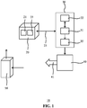
- FIG. 1 schematically depicts an air purification system 10 according to an embodiment.
- the air purification system 10 is adapted to monitor the performance of one or more pollutant removal structures such as air filters, catalytic converters, electrostatic precipitators, and so on in an air purifier 50.
- the performance of an air filter may be expressed as the ability of the air filter to lower a concentration of a pollutant in a defined amount of time given a defined air flow through the pollutant removal structure as induced by the air purifier 50 when placed in a space such as a room of a house, office building or the like.
- Such air purifiers 50 are typically arranged to suck in air and pass this air through or over one or more pollutant removal structures before expelling the purified air, as indicated by the ingoing and outgoing arrow respectively in FIG. 1 .
- Such air purifiers 50 may contain any suitable type of pollutant removal structures, e.g. filters such as HEPA filters, carbon filters, and so on in order to remove pollutants such as particulate matter, pollen, odours, bacteria, formaldehyde, volatile organic compounds (VOCs) and so on from the atmosphere in the space in which such an air purifier 50 is placed.
- the air purification system 10 typically comprises a computing device 30 including a processor 31.
- the computing device 30 may be any suitable computing device, such as a personal computer, e.g. a desktop computer or a laptop computer, a tablet computer, a personal digital assistant, a mobile communication device such as a smartphone and so on.
- the computing device 30 may form an assembly with the air purifier 50. In such an assembly, the computing device 30 may be a discrete entity or may form part of the air purifier 50, i.e. the air purifier 50 may comprise the processor 31.
- the processor 31 may be any suitable processor, e.g. a generic processor or an application-specific processor.
- the computing device 30 further comprises a data storage device 33 communicatively coupled to the processor 31.
- the computing device 30 is arranged to communicate with one or more sensors 21, 23 for sensing pollutant levels in the atmosphere in the space in which the air purifier 50 is placed.
- at least one sensor of the one or more sensors is arranged to sense a concentration or level of a pollutant for which the air purifier 50 comprises a pollutant removal structure such as an air filter or the like arranged to remove this pollutant.
- the one or more sensors 21, 23 may comprise a particulate matter sensor such as a PM 2.5 sensor for detecting particulate matter of a certain diameter in the atmosphere, e.g. PM2.5 or PM10, dust particles, allergens, or the like.
- the one or more sensors 21, 23 may be integrated in any suitable device, such as the air purifier 50, the computing device 30 or a stand-alone sensor device 20, e.g. a sensor box or the like.
- Stand-alone sensor devices e.g. sensor boxes, are increasingly available for home-use and may include sensors for measuring air pollutants such as volatile organic compounds (VOCs), particulates including PM2.5, formaldehyde, as well as environmental parameters such as relative humidity and temperature.
- the processor 31 may be adapted to monitor the concentration of a particular pollutant based on the sensor data provided by a sensor 21, 23 of the sensor device 20.
- the processor 31 may be integrated into such a stand-alone sensor device 20, i.e. the stand-alone sensor device 20 may comprise the computing device 30.
- At least some of the sensors 21, 23 are communicatively coupled to the computing device 30 over a communication link 25 such that the processor 31 can receive sensor readings from such sensors.
- a communication link may be a wired communication link, e.g. in case the one or more sensors are integral to the computing device 30, or may be a wireless communication link, e.g. in case the one or more sensors 21, 23 are located in a different device to the computing device 30, e.g. in a stand-alone sensor device 20.
- the respective devices communicatively coupled over such a wireless communication link may include a wireless transceiver (not shown). The devices may communicate with each other through their respective wireless transceivers using any suitable wireless communication protocol, e.g.
- the respective devices may communicate directly with each other or may communicate with each other through an intermediary such as a wireless bridge, a router, a hub, and so on. Any suitable embodiment of wired or wireless communication between such respective devices may be contemplated.
- the processor 31 is further communicatively coupled to a data storage device 33, here shown to form part of the computing device 30.
- a data storage device may be any suitable device for storing digital data, e.g. a random access memory, a cache memory, a Flash memory, a solid state storage device, a magnetic storage device such as hard disk, an optical storage device and so on.
- the data storage device 33 may be separate from the computing device 30, e.g. a network storage device or a cloud storage device accessible to the processor 31 over a network such as a LAN or the Internet.
- the processor 31 may store sensor data received from the connected one or more sensors 21, 23 in the data storage device in order to collect and store historical data regarding the pollutant levels of interest in the atmosphere within the space comprising the air purifier 50 from which the processor 31 may derive the pollutant removal performance of a pollutant removal structure in the air purifier 50 adapted to remove the pollutant of interest from the atmosphere.
- the processor 31 may be adapted to store historical pollutant concentrations in the data storage device 33.
- the processor 31 may be adapted to calculate a pollutant decay constant from a series of pollutant measurements performed with the sensor device 20 as an indication of the efficiency of a particular pollutant removal structure of the air purifier 50, and store the calculated pollutant decay constant in the data storage device 33 to build up a library of historical pollutant decay constants, for example to predict an End Of Life (EOL) of a pollutant removal structure of the air purifier 50 responsible for the monitored pollutant decay.
- EOL End Of Life
- the computing device 30 further comprises a sensory output device 35 under control of the processor 31.
- a sensory output device may be any device that capable of producing an output that can be detected by one of the human senses.
- the sensory output device 35 may be adapted to produce a visible or audible output.
- the processor 31 may be adapted to generate a control signal indicative of an estimated EOL of a monitored pollutant removal structure, which control signal triggers the sensory output device 35 to produce a sensory output indicating the estimated EOL.
- the sensory output device 35 may comprise a display and/or one or more LEDs adapted to provide an indication of the estimated EOL of a particular filter monitored by the processor 31.
- the processor 31 may be adapted to receive sensor data from a plurality of sensors 21, 23 each associated with different pollutant of interest, with the processor 31 adapted to (simultaneously) monitor the respective concentration levels of different pollutants of interest from the sensor data received from the multiple sensors in the sensor device 20.
- the sensory output device 35 forms part of the computing device 30, e.g. may be an integral part of the computing device 30 or may be attached to the computing device 30, e.g. a monitor or loudspeaker attached to the computing device 30.
- the sensory output device 35 may form part of a mobile communication device, with the computing device 30 adapted to communicate with the mobile communication device over a wireless communication link, e.g. using any of the aforementioned wireless communication protocols.
- a user may be kept informed of the estimated EOL of one or more of the pollutant removal structures in the air purifier 50 even when not in direct vicinity of the computing device 30, e.g. when being in a different room or being outside the building comprising the air purifier 50.
- the processor 31 is adapted to calculate the room volume of a room housing the air purifier 50 and the sensor device 20 from a pollutant decay rate derived from the sensor data provided by the one or more sensors 21, 23.
- the processor 31 may be provided with the purification capabilities of the air purifier 50, i.e. with the purification capabilities of a pollutant removal structure in the air purifier 50, which purification capabilities may be expressed in terms of a reference pollutant decay rate for a unit volume (V ref ), e.g. 100 ppm per minute for a room volume of 10 m 3 .
- the actual room volume may then be determined in any suitable manner, e.g. by determining an actual decay rate and extrapolating the actual decay rate based on the reference decay rate to find the actual room volume (V actual ) as per equation (1):
- V actual reference decay rate / actual decay rate * V ref
- the determination of the actual room volume V actual in some embodiments may be performed upon replacement of a pollutant removal structure of the air purifier 50, which has the advantage that the pollutant capture capabilities of the pollutant removal structure are well-defined, because the pollutant removal structure is not yet contaminated with captured pollutants.
- the determined filter efficiency may be used to scale the reference decay rate in order to find the actual room volume as per equation (3):
- V actual FE * reference decay rate / actual decay rate * V ref It is noted that in equation (1) the actual decay rate equals the maximum decay rate of a pollutant removal structure because the actual room volume is determined with a new pollutant removal structure (i.e. having maximum pollutant capturing capability) such that the scaling of the reference decay rate is unnecessary.
- a typical CADR curve may be recorded by a sensor 21, 23, e.g. may be expressed using a linear scale on the y-axis of a plot depicting the CADR curve.
- CADR V k v P p C out C + k ⁇ k 0 ⁇ k v
- CADR V 0 0.8 k v C out C + k ⁇ k v ⁇ 0.2
- the initial CADR may be used to calculate the room volume Vo.
- This room volume for instance may be obtained when the air purifier 50 is operated for the first time in a sealed room.
- the air purification system 10 may comprise a user interface, e.g. as part of the sensor device 20, the computing device 30 or the air purifier 50 that allows a user to specify a room volume of the room in which the air purification system 10 is installed.
- the user interface may be communicatively coupled to the processor 31 such that the user-specified room volume may be communicated to the processor 31.
- the processor 31 may be adapted to store the calculated or user-defined room volume in the data storage device 33 for future use, as will be explained in more detail below. Other suitable ways of obtaining the room volume may be applied instead.
- the air purification system 10 further comprises a scent release apparatus 40 adapted to release a scent 41 into a room in which the air purification system 10 is installed.
- the scent release apparatus 40 typically comprises one or more scent release stages for releasing an aroma compound into the room.
- an aroma compound is a volatile compound that defines at least part of a scent to be created by the scent release apparatus 40.
- An example embodiment of such a scent release apparatus 40 will be described in further detail below.
- the scent release apparatus 40 is responsive to the processor 31. More specifically, the processor 31 is adapted to generate a scent release signal that allows the scent release apparatus 40 to release a scent in response to this signal. This facilitates the control of the release of a particular scent by the scent release apparatus 40 upon the processor 31 generating dissent release signal once a particular precondition for the safe release of the scent into the room has been met.
- the processor 31 may be adapted to monitor the concentration of a pollutant of interest in the room from the sensor data provided by at least one of the sensors 21, 23 of the sensor device 20 and to generate the scent release signal once the monitored concentration of the pollutant of interest has fallen below a defined threshold.
- a threshold for example may be defined on the basis of the safe concentration of the pollutant of interest within the room such that the concentration of reaction products of the pollutant of interest with an aroma compound released by the scent release apparatus 40 does not reach harmful levels.
- the processor 31 may periodically repeat the generation of the scent release signal and its provision to the scent release apparatus 40, e.g. to invoke the generation of a pulsed release of a scent in order to retain the scent concentration within the room at a desired level. This periodic repetition of the scent release signal generation preferably is performed as long as the monitored concentration of the pollutant of interest remains below a defined threshold such that the scent may be safely released into the room as previously explained.
- the processor 31 may be adapted to periodically generate the scent release signal and to alter the target scent delivery stage of the scent release apparatus 40 to which the scent release signal is delivered.
- the scent release apparatus 40 may periodically alter the scent delivery stage to which a scent release signal received from the processor 31 is delivered.
- a different scent may be periodically generated to dynamically alter the scent within the room. This may counter olfactory adaptation of the inhabitants of the room to a previously released scent, i.e. the scent becoming unnoticeable to these inhabitants and may improve the appreciation of the inhabitants to the scented atmosphere being created by the air purification system 10.
- the scent release apparatus 40 may comprise or may be responsive to a user interface (not shown) that allows a user to specify which scent should be released by the scent release apparatus 40.
- the scent release apparatus 40 may comprise a plurality of scent release stages, with the scent release apparatus 40 or the processor 31 being configured to direct the scent release signal to a user-specified scent release stage, i.e. one or more stages comprising the aroma compound(s) that are defined the user-specified scent.
- the user interface may allow a user to specify a sequence of scents to be released by the scent release apparatus 40, which sequence may define the periodic alteration of the scent to be released by the scent release apparatus 40 as previously explained.
- such a user interface may be provided in software as an app on a mobile communication device such as a tablet computer, smart phone or the like, with the mobile communication device communicatively coupled to the computing device 30 and/or the scent release apparatus 40.
- the processor 31 is adapted to delay the generation of the scent release signal following the determination that the concentration of a particular pollutant of interest has fallen below the defined threshold.
- a delay in some embodiments may be user-defined, for example by a user specifying the delay on a user interface of the air purification system 10.
- the processor 31 is further adapted to control the scent release apparatus 40 such that the amount of aroma compound released in response to the scent release signal generated by the processor 31 is adapted to the room volume of the room into which the aroma compound is released.
- the processor 31 may utilise the above explained calculated or user-defined room volume of the room housing the air purification system 10 in order to control the amount of the aroma compound to be released by the scent release apparatus 40.
- the processor 31 may be configured with scent release information provided by the scent release apparatus 40, such as a rate at which an aroma compound is released, e.g. as parts per second.
- the processor 31 may be further configured with the target concentration information of the aroma compound within the room, e.g.
- the amount of aroma compound to be released can be controlled by providing the scent release apparatus 40 with the scent release signal for a determined period of time, which period of time can be determined from the room volume, scent release rate and target scent concentration in the room.
- the scent concentration in the room can be accurately controlled, thereby reducing the risk that the inhabitants of the room perceive the scent as intrusive or unpleasant due to excessive concentrations of the scent in the room.
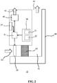
- FIG. 2 schematically depicts an example embodiment of an air purification system 10 embodied by an air purifier 50 having an air inlet 53, an air outlet 55 and an air purification path 51, e.g. a fluid conduit, extending between the air inlet 53 and the air outlet 55.
- One or more pollutant removal structures 57 are located in the air purification path 51 between the air inlet 53 and the air outlet 55.
- a fan 59 may be located in the air purification path 51 to control the flow rate of air through the air purification path 51. The fan 59 may be controlled by the processor 31 integral to the air purification apparatus.
- the processor 31 may be further adapted to regulate the fan speed of the fan 59 in response to sensor data provided by the one or more sensors 21, 23 to ensure that the air quality in the confined space in which the air purification apparatus is placed is appropriately regulated.
- sensor-based fan speed regulation is well-known per se, this is not further explained for the sake of brevity only.
- the sensor device 20 may also be integral to the air purification apparatus in this embodiment although in alternative embodiments the sensor device 20 may be separate to the air purifier 50.
- the air purifier 50 may further comprise a user interface 37 to provide the air purifier 50 with user control instructions, e.g. a fan speed regulation instruction or the like.
- Such a user interface 37 may take any suitable form, e.g. a touch screen, one or more buttons and/or one or more switches.
- the air purifier 50 further comprises the scent release apparatus 40 for releasing a scent 41 into the room in which the air purifier 50 is positioned in response to the scent release signal provided by the processor 31 as explained above.
- FIG. 3 schematically depicts an alternative embodiment of an air purification system 10 embodied by the air purifier 50.
- the air purifier 50 may be at least partially controlled by a mobile communication device 60 having a user interface 61 such as a touchscreen or the like.
- a mobile communication device 60 may be used to configure the scent release apparatus 40.
- a user of the mobile communication device 60 may specify which scent 41 or sequence of scents 41 is to be released by the scent release apparatus 40 in response to the scent release signal generated by the processor 31.
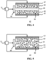
- FIG. 4 schematically depicts an aspect of an example embodiment of a scent release apparatus 40 in more detail.
- the scent release apparatus 40 may comprise one or more scent delivery stages 42.
- Each scent delivery stage 42 may comprise a capillary 45 delimited by an absorbent material 43 into which the aroma compound 44 may be absorbed.
- Such an absorbent material 43 for example may be an absorbent polymer such as a polysiloxane, e.g. PDMS or any other suitable absorbent polymer.
- the absorbent material 43 may be a gel in which the aroma compound 44 is absorbed.
- such an absorbent material includes materials that are permeable to such an aroma compound 44 such as but not necessarily porous materials.
- the aroma compound 44 may be a liquid compound as well as a solid compound distributed through the absorbent material 43.
- the actuation of the actuator 47 e.g. a heating element, may cause the sublimation of the solid aroma compound 44 from the absorbent material 43 into the capillary 45.
- Each scent delivery stage 42 may comprise a single aroma compound 44 or a mixture of aroma compounds 44, e.g. a perfume or the like having a particular scent.
- Each scent delivery stage 42 further comprises a scent release actuator 47, e.g. a heating element, which is thermally coupled to the absorbent material 43.
- the scent release actuator 47 may be arranged such that at least partially surrounds the absorbent material 43.
- the heating element 47 envelopes the absorbent material 43, such that it provides an airtight seal around the absorbent material.
- the heating element may comprise a gas-impermeable material such as glass for instance.
- the scent release actuator 47 may be responsive to the scent release signal generated by the processor 31 such that the scent release actuator 47 is activated in response to this scent release signal.
- the capillary 45 of each scent delivery stage 42 is fluidly coupled to an air displacement apparatus 49r for forcing the aroma compound 44 from the capillary 45.
- the air displacement apparatus 49 may comprise a fan under control of the processor 31, i.e. the fan is arranged such that upon its activation, the fluid contents in the capillary 45 are forced out of the capillary into the room in which the air purification system 10 is housed.
- the air displacement apparatus 49 may comprise a compressor, micropump or the like.
- the processor 31 may provide the scent release actuator 47 with the scent release signal, causing the absorbent material 43 to be heated by the heating element. This causes the partial evaporation of the aroma compound 44 from the porous material 43 into the capillary 45 as schematically depicted in FIG. 5 .
- the processor 31 may retain the scent release signal for a period of time (and optionally may further control the heating temperature generated by the heating element) in order to control the amount of aroma compound 44 that is released from the absorbent material 43 into the capillary 45.
- the duration of this scent release signal in order to control the amount of aroma compound 44 to be released may be derived from the room volume of the room in which the air purification system 10 is located in order to control the concentration of the scent 41 to be released in this room.
- the processor 31 may be further adapted to generate a further control signal, e.g. a delayed version of the scent release signal to activate the air displacement apparatus 49 in order to force the evaporated aroma compound 44 from the capillary 45 into the room, as schematically depicted in FIG. 6 .
- the generation of the further control signal is typically delayed by the amount of time required to generate the desired amount of aroma compound 44 in the capillary 45 as will be readily understood by the skilled person.
- each capillary 45 may further comprise a sealing member such as a valve at its outlet under control of the processor 31.
- the sealing member may be switchable between a first position in which the capillary 45 is open and a second position in which the capillary 45 is closed.
- the processor 31 may be adapted to switch the sealing member to the first position at the same time as activating the air displacement apparatus 49 such that the aroma compound 44 can be released from the capillary 45.
- the processor 31 may be further adapted to switch to sealing member to the second position after a defined period of time that is sufficient to effectively force the aroma compound 44 from the capillary 45 with the air displacement apparatus 49, thereby sealing the capillary 45 and preventing the uncontrolled release of the aroma compound 44 from the capillary 45, which uncontrolled release may cause the concentration of the aroma compound 44 within the room in which the air purifying system 10 is positioned to reach unacceptably high levels, e.g. levels that are perceived as unpleasant by the inhabitants of the room.
- the processor 31 may be configured to generate the scent release signal as a function of the amount of aroma compound 44 in the absorbent material 43.
- the processor 31 may be configured with knowledge of the total amount of aroma compound 44 in the absorbent material 43 and may record the amount of aroma compound 44 previously released from the absorbent material 43 to determine the actual amount of aroma compound 44 in the absorbent material 43.
- the actual amount of aroma compound 44 in the absorbent material 43 as monitored by the processor 31 for example may be used by the processor 31 to set the temperature of the heating element in thermal contact with the absorbent material 43.
- the processor 31 may employ a correlation function or a lookup table or the like in which a particular amount of aroma compound and the absorbent material 43 is linked to a particular temperature at which the absorbent material 43 should be heated in order to invoke the release of the desired amount of the aroma compound 44 from the absorbent material 43.
- the processor 31 may be further adapted to generate the scent release signal as a function of the particular aroma compound 44.
- different aroma compounds will have different partial pressures (i.e. a different volatility) at a given temperature, such that the release characteristics of the aroma compound 44 from the absorbent material 43 may be different for aroma compounds 44 having different partial pressures.
- the processor 31 may be adapted to tailor the duration of the scent release signal to the relevant partial pressure of the aroma compound 44 to be released. As the rate of release of a particular compound as a function of its partial pressure at a given temperature is well-known per se, this will not be explained in further detail for the sake of brevity.
- the dimensions of the capillary 45 e.g. length and diameter of the capillary 45 and the thickness of the absorbent material 43 delimiting the capillary 45 may be chosen in accordance with the desired capacity and scent release characteristics of the scent delivery stage.
- the scent delivery stages 42 of the scent release apparatus 40 may be arranged such that the scent delivery stages 42 are at least periodically brought into contact with respective reservoirs containing the aroma compound 44 or mixture of aroma compounds 44 to be absorbed in the absorbent material 43 of the respective scent delivery stages 42 such that the aroma compound 44 or mixture of aroma compounds 44 in the absorbent material 43 may be periodically replenished.
- FIG. 7 schematically depicts an example embodiment of such an arrangement in which the respective scent delivery stages 42 are mounted on a rotation axle 46 under control of the processor 31.
- the rotation axle 46 may be configured to be rotated between a first orientation in which the absorbent material 43 of each scent delivery stage 42 is dipped into a reservoir 48 containing the aroma compound 44 or mixture of aroma compounds 44 such that the absorbent material 43 can be replenished by absorbing the aroma compound 44 or mixture of aroma compounds 44 from the reservoir 48 and a second orientation in which the replenished absorbent materials 43 of the respective scent delivery stages 42 are aligned with the air displacement apparatus 49 (not shown in FIG. 7 ).
- the processor 31 may be adapted to control the rotation axle 46 as a function of the monitored amounts of aroma compounds 44 in the respective absorbent materials 43 such that the rotation axle 46 is forced into the first orientation by the processor 31 upon at least one of the absorbent materials 43 being depleted of aroma compound 44 or mixture of aroma compounds 44 therein.
- FIG. 7 is by way of non-limiting examples only and that many other arrangements that facilitate the periodic replenishment of aroma compounds 44 in the respective absorbent materials 43, e.g. an arrangement in which the disposable cartridges containing the aroma compounds may be in fluid communication with the respective absorbent materials 43, are equally feasible and may be equally contemplated.
- FIG. 8 is a flowchart of a method 100 according to an embodiment.
- the method 100 is for generating a scented atmosphere in a room housing an air purification apparatus 50 for removing a pollutant from the air in the room.
- the method 100 starts in 101, e.g. by switching on the air purification apparatus 50, after which the method 100 proceeds to 103 in which a pollution level of a pollutant of interest in the room is monitored, e.g. using one or more sensors 21, 23 of the previously described sensor device 20.
- the method 100 may proceed to 107 in which a scent is released into the room, which may be a user-specified scent as previously explained.
- a scent is released into the room, which may be a user-specified scent as previously explained.
- the release of the scent into the room may be periodically repeated as long as the monitored pollution level remains below the defined threshold in order to replenish the scent in the room.
- periodic release may involve the release of different scents at different points in time in order to create a dynamic scent atmosphere within the room.
- a dynamic scent atmosphere may be user-specified.
- the release of the scent into the room in 107 further comprises obtaining the room volume and releasing an amount of the scent into the room in accordance with the obtained room volume such that the scent concentration in the room is accurately controlled.
- a room volume may be obtained through calculation or user input as explained in more detail above. In this manner, overexposure of inhabitants of the room to the released scent can be avoided, which overexposure may be perceived as unpleasant or indeed may be unhealthy, e.g. cause allergic or asthmatic reactions.
- the method 100 may terminate in 109.
Landscapes
- Engineering & Computer Science (AREA)
- Chemical & Material Sciences (AREA)
- Signal Processing (AREA)
- General Engineering & Computer Science (AREA)
- Mechanical Engineering (AREA)
- Combustion & Propulsion (AREA)
- Health & Medical Sciences (AREA)
- Fuzzy Systems (AREA)
- Mathematical Physics (AREA)
- Physics & Mathematics (AREA)
- Life Sciences & Earth Sciences (AREA)
- Public Health (AREA)
- General Health & Medical Sciences (AREA)
- Animal Behavior & Ethology (AREA)
- Veterinary Medicine (AREA)
- Epidemiology (AREA)
- Analytical Chemistry (AREA)
- General Chemical & Material Sciences (AREA)
- Oil, Petroleum & Natural Gas (AREA)
- Chemical Kinetics & Catalysis (AREA)
- Disinfection, Sterilisation Or Deodorisation Of Air (AREA)
Description
- The present invention relates to an air purification system comprising an air purifier apparatus for removing a pollutant from air, a sensor for sensing a concentration of the air pollutant and a scent release apparatus.
- The present invention further relates to a method of generating a scented atmosphere in a room housing an air purification apparatus for removing a pollutant from the air in the room.
- Scent release devices such as air fresheners are commonly used to create a scented atmosphere in a confined space such as a room. This for instance may be done to mask unpleasant smells or simply to generate a pleasant atmosphere within the confined space, such as a flowery smell, a forest-like smell, a sea smell and so on.
- For example,
US 2009/0162253 A1 discloses a volatile material diffuser that includes a housing and first and second containers holding first and second volatile materials and having first and second wicks, respectively, in contact with respective volatile materials and extending out of respective containers, wherein the containers are inserted into and detachably attached to the housing. The diffuser further includes first and second heaters disposed within the housing adjacent the first and second wicks, respectively, to vaporize the first and second volatile materials, respectively. -
WO2014011063 discloses an air treatment unit for use at e.g. outlets of ventilation ducts in e.g. buildings, equipped with a fragrance dispenser and an air contamination sensor and/or set of air contamination sensors, for sensing contaminants in air flowing through duct or duct airflow, and connected with control unit for controlling air circulation device. - However, the use of such scent release devices is not without issues. For example, excessive release of the volatile compounds can lead to a perception of an overwhelming scent in the confined space, which often is perceived as unpleasant. What is more, many of the volatile compounds used to create a scented environment are reactive organic molecules that may react with pollutants in the atmosphere within the confined space to create reaction products that are potentially harmful to the inhabitants of the confined space. For example, isoprene can react with hydroxyl radicals or ozone to form harmful compounds such as methyl vinyl ketone and methacrylaldehyde. In order to reduce the risk of the generation of such harmful compounds, the scent release device may be combined with an air purifier or air conditioner such as for example disclosed in utility model
KR 2009/08236U - The present invention seeks to provide an air purification system that reduces the risk of the generation of harmful reaction products when releasing a scent into air.
- The present invention further seeks to provide an air purification method that reduces the risk of the generation of harmful reaction products when releasing a scent into air.
- According to an aspect, there is provided an air purification system comprising an air purifier apparatus for removing a pollutant from air, a sensor for sensing a concentration of the air pollutant and a scent release apparatus responsive to a scent release signal, wherein the air purification system further comprises a processor adapted to monitor the pollutant concentration from sensor data received from the sensor and to generate the scent release signal upon the monitored pollutant concentration falling below a defined threshold.
- The processor thus comprises a monitoring means for monitoring the pollutant concentration, a threshold setting means, and a scent release signal generation means which receives as input the the monitored pollutant concentration and the threshold set by the threshold setting means and generates the scent release signal, wherein the threshold set is a maximum concentration for the air pollutant during which scent may be released.
- Of course, the scent release signal may be generated without delay if the pollutant concentration is already sufficiently low. If the concentration is too high, the apparatus will wait for the concentration to drop and thereby delay a scent release.
- By linking the release of a volatile compound used to create a scent to the concentration of an air pollutant with which the volatile compound may react, the risk of the creation of harmful reaction products from the reaction of the volatile compound with the air pollutant is reduced. Consequently, such an air purification system is capable of delivering a scented atmosphere in a room with a reduced risk of harming the health of the inhabitants of such a room.
- The air purification system may be a distributed system in which the processor, the sensor and/or the scent release apparatus may be separate to the air purifier apparatus. Alternatively, the scent release apparatus and the processor are integral to the air purifier apparatus, which has the advantage that the complete functionality of the air purification system according to embodiments of the present invention is delivered within a single device, which is more cost-effective.
- In a preferred embodiment, the processor is adapted to generate the scent release signal as a function of a determined volume of a room housing the air purifier apparatus. In this manner, the processor may control the amount of volatile compounds to be released into the room in accordance with the room volume, such that the inhabitants of the room are not overexposed to the scent, i.e. the concentration of volatile compounds forming the scent is controlled to avoid the inhabitants of the room perceiving the scent as unpleasant.
- The processor may be adapted to determine said volume from a decay rate of the monitored pollutant concentration and a defined pollutant removal capacity of the air purifier apparatus. This has the advantage that the air purification system can autonomously determine the room volume without requiring user intervention, e.g. a user having to specify the volume of a room into which the air purification system is installed.
- The processor may be adapted to periodically repeat the generation of the scent release signal if the monitored pollutant concentration remains below the defined threshold in order to maintain the concentration of the scent at levels that are perceived as being pleasant by the inhabitants of the room. In an embodiment where the scent release apparatus is configurable to release a plurality of different scents, the processor may be adapted to periodically alter the scent to be released by the scent release apparatus to counter olfactory adaptation of the inhabitants of the room to the previously released scent. In this embodiment, the inhabitants are exposed to a dynamically changing scented atmosphere within the room, which may be perceived as particularly pleasant.
- Although the scent release apparatus may be implemented in any suitable manner, in an embodiment the scent release apparatus comprises at least one scent delivery stage comprising an aroma compound, e.g. a volatile compound for generating at least part of a scent; and a scent release actuator arranged to trigger a release of an aroma compound from at least one of said scent delivery stages in response to the scent release signal. Each scent delivery stage may comprise a capillary delimited by an absorbent material comprising the aroma compound, which has the advantage that an amount of the aroma compound may be released by the scent release apparatus in a well-defined manner.
- For example, the processor may be adapted to maintain the scent release signal for a period of time; and calculate said period of time based on an estimated amount of the aroma compound in a particular absorbent material to control the amount of the aroma compound to be released into the capillary.
- In order to promote the release of the aroma compound into such a capillary, the scent release actuator may further comprise a heating element thermally coupled to the at least one scent delivery stage. The heating element preferably provides an airtight seal around the scent delivery stage to avoid evaporation of the aroma compound from the scent delivery stage.
- In a preferred embodiment, the scent release apparatus comprises a plurality of said scent delivery stages, wherein the scent release actuator is arranged to trigger a release of a user-selected aroma compound from at least one of said scent delivery stages in response to the scent release signal. Alternatively or additionally, the processor may be adapted to periodically alter which scent delivery stage the scent release signal is delivered to in order to create the previously mentioned dynamically altering scent atmosphere within the room. The scent release actuator may further comprises an air displacement apparatus responsive to the scent release signal, wherein the air displacement apparatus is arranged to force air through the at least one of the scent delivery stages. This has the advantage that the aroma compounds released by the scent delivery stages are rapidly delivered to the room in which the air purification system is installed.
The processor may be adapted to provide the scent release signal to the air displacement apparatus after a time delay from providing the heating element with the scent release signal in order to allow the relevant capillary to be filled with the desired amount of the aroma compound before the air displacement apparatus forces the aroma compound from the capillary. - In an embodiment, the air purification system may further comprise a reservoir for containing the aroma compound for each scent delivery stage, wherein each scent delivery stage at least periodically is in fluid communication with a reservoir for said scent delivery stage to replenish the aroma compound in the scent delivery stage.
- According to another aspect, there is provided a method of generating a scented atmosphere in a room housing an air purification apparatus for removing a pollutant from the air in the room, the method comprising monitoring a concentration of the pollutant; and releasing at least one aroma compound into the room upon the monitored pollutant concentration falling below a defined threshold. In this manner, the risk of reactions between the released aroma compound and the monitored pollutant that can lead to harmful reaction products is reduced, thereby providing a safe method of generating such a scented atmosphere.
- In a preferred embodiment, the method further comprises obtaining a room volume of the room from a decay rate of the pollutant concentration; calculating an amount of the at least one aroma compound to be released in the room based on the obtained room volume; and releasing the calculated amount of the at least one aroma compound into the room upon the monitored concentration falling below a defined threshold.
- This ensures that the amount of aroma compound(s) released into the room is tailored to the volume of the room, thereby avoiding overexposure of the inhabitants of the room to the released aroma compound(s), which therefore reduces the risk of the inhabitants perceiving the release of the aroma compound(s) as unpleasant because of an excessive amount of the aroma compound(s) being released.
- Embodiments of the invention are described in more detail and by way of non-limiting examples with reference to the accompanying drawings, wherein:
-
FIG. 1 schematically depicts an air purification system according to an embodiment; -
FIG. 2 schematically depicts an air purification system according to another embodiment; -
FIG. 3 schematically depicts an air purification system according to yet another embodiment; -
FIG. 4-6 schematically depict the controlled release of an aromatic compound from a scent releasing apparatus of the air purification system according to an embodiment; -
FIG. 7 schematically depicts an aspect of such a scent releasing apparatus according to an example embodiment; and -
FIG. 8 is a flowchart of a scented atmosphere generating method according to an embodiment. - It should be understood that the Figures are merely schematic and are not drawn to scale. It should also be understood that the same reference numerals are used throughout the Figures to indicate the same or similar parts.
-
FIG. 1 schematically depicts anair purification system 10 according to an embodiment. Theair purification system 10 is adapted to monitor the performance of one or more pollutant removal structures such as air filters, catalytic converters, electrostatic precipitators, and so on in anair purifier 50. In the context of the present application, the performance of an air filter may be expressed as the ability of the air filter to lower a concentration of a pollutant in a defined amount of time given a defined air flow through the pollutant removal structure as induced by theair purifier 50 when placed in a space such as a room of a house, office building or the like.Such air purifiers 50 are typically arranged to suck in air and pass this air through or over one or more pollutant removal structures before expelling the purified air, as indicated by the ingoing and outgoing arrow respectively inFIG. 1 .Such air purifiers 50 may contain any suitable type of pollutant removal structures, e.g. filters such as HEPA filters, carbon filters, and so on in order to remove pollutants such as particulate matter, pollen, odours, bacteria, formaldehyde, volatile organic compounds (VOCs) and so on from the atmosphere in the space in which such anair purifier 50 is placed. - The
air purification system 10 typically comprises acomputing device 30 including aprocessor 31. Thecomputing device 30 may be any suitable computing device, such as a personal computer, e.g. a desktop computer or a laptop computer, a tablet computer, a personal digital assistant, a mobile communication device such as a smartphone and so on. Thecomputing device 30 may form an assembly with theair purifier 50. In such an assembly, thecomputing device 30 may be a discrete entity or may form part of theair purifier 50, i.e. theair purifier 50 may comprise theprocessor 31. Theprocessor 31 may be any suitable processor, e.g. a generic processor or an application-specific processor. Thecomputing device 30 further comprises adata storage device 33 communicatively coupled to theprocessor 31. - The
computing device 30 is arranged to communicate with one ormore sensors air purifier 50 is placed. Typically, at least one sensor of the one or more sensors is arranged to sense a concentration or level of a pollutant for which theair purifier 50 comprises a pollutant removal structure such as an air filter or the like arranged to remove this pollutant. For example, the one ormore sensors more sensors air purifier 50, thecomputing device 30 or a stand-alone sensor device 20, e.g. a sensor box or the like. Stand-alone sensor devices, e.g. sensor boxes, are increasingly available for home-use and may include sensors for measuring air pollutants such as volatile organic compounds (VOCs), particulates including PM2.5, formaldehyde, as well as environmental parameters such as relative humidity and temperature. Theprocessor 31 may be adapted to monitor the concentration of a particular pollutant based on the sensor data provided by asensor sensor device 20. In an embodiment, theprocessor 31 may be integrated into such a stand-alone sensor device 20, i.e. the stand-alone sensor device 20 may comprise thecomputing device 30. - At least some of the
sensors computing device 30 over acommunication link 25 such that theprocessor 31 can receive sensor readings from such sensors. Such a communication link may be a wired communication link, e.g. in case the one or more sensors are integral to thecomputing device 30, or may be a wireless communication link, e.g. in case the one ormore sensors computing device 30, e.g. in a stand-alone sensor device 20. To this end, the respective devices communicatively coupled over such a wireless communication link may include a wireless transceiver (not shown). The devices may communicate with each other through their respective wireless transceivers using any suitable wireless communication protocol, e.g. Bluetooth, Wi-Fi, a mobile communication protocol such as 2G, 3G, 4G or 5G, a suitable near-field communication (NFC) protocol or a proprietary protocol. In case of such wireless communication, the respective devices may communicate directly with each other or may communicate with each other through an intermediary such as a wireless bridge, a router, a hub, and so on. Any suitable embodiment of wired or wireless communication between such respective devices may be contemplated. - The
processor 31 is further communicatively coupled to adata storage device 33, here shown to form part of thecomputing device 30. Such a data storage device may be any suitable device for storing digital data, e.g. a random access memory, a cache memory, a Flash memory, a solid state storage device, a magnetic storage device such as hard disk, an optical storage device and so on. Alternatively, thedata storage device 33 may be separate from thecomputing device 30, e.g. a network storage device or a cloud storage device accessible to theprocessor 31 over a network such as a LAN or the Internet. Theprocessor 31 may store sensor data received from the connected one ormore sensors air purifier 50 from which theprocessor 31 may derive the pollutant removal performance of a pollutant removal structure in theair purifier 50 adapted to remove the pollutant of interest from the atmosphere. Theprocessor 31 may be adapted to store historical pollutant concentrations in thedata storage device 33. Alternatively or additionally, theprocessor 31 may be adapted to calculate a pollutant decay constant from a series of pollutant measurements performed with thesensor device 20 as an indication of the efficiency of a particular pollutant removal structure of theair purifier 50, and store the calculated pollutant decay constant in thedata storage device 33 to build up a library of historical pollutant decay constants, for example to predict an End Of Life (EOL) of a pollutant removal structure of theair purifier 50 responsible for the monitored pollutant decay. - In
FIG. 1 , thecomputing device 30 further comprises asensory output device 35 under control of theprocessor 31. Such a sensory output device may be any device that capable of producing an output that can be detected by one of the human senses. For example, thesensory output device 35 may be adapted to produce a visible or audible output. Theprocessor 31 may be adapted to generate a control signal indicative of an estimated EOL of a monitored pollutant removal structure, which control signal triggers thesensory output device 35 to produce a sensory output indicating the estimated EOL. For example, thesensory output device 35 may comprise a display and/or one or more LEDs adapted to provide an indication of the estimated EOL of a particular filter monitored by theprocessor 31. - As will be readily understood by the skilled person, the
processor 31 may be adapted to receive sensor data from a plurality ofsensors processor 31 adapted to (simultaneously) monitor the respective concentration levels of different pollutants of interest from the sensor data received from the multiple sensors in thesensor device 20. - In the above embodiment, the
sensory output device 35 forms part of thecomputing device 30, e.g. may be an integral part of thecomputing device 30 or may be attached to thecomputing device 30, e.g. a monitor or loudspeaker attached to thecomputing device 30. In an alternative arrangement (not shown), thesensory output device 35 may form part of a mobile communication device, with thecomputing device 30 adapted to communicate with the mobile communication device over a wireless communication link, e.g. using any of the aforementioned wireless communication protocols. In this embodiment, a user may be kept informed of the estimated EOL of one or more of the pollutant removal structures in theair purifier 50 even when not in direct vicinity of thecomputing device 30, e.g. when being in a different room or being outside the building comprising theair purifier 50. - In an embodiment, the
processor 31 is adapted to calculate the room volume of a room housing theair purifier 50 and thesensor device 20 from a pollutant decay rate derived from the sensor data provided by the one ormore sensors processor 31 may be provided with the purification capabilities of theair purifier 50, i.e. with the purification capabilities of a pollutant removal structure in theair purifier 50, which purification capabilities may be expressed in terms of a reference pollutant decay rate for a unit volume (Vref), e.g. 100 ppm per minute for a room volume of 10 m3. The actual room volume may then be determined in any suitable manner, e.g. by determining an actual decay rate and extrapolating the actual decay rate based on the reference decay rate to find the actual room volume (Vactual) as per equation (1):
- The determination of the actual room volume Vactual in some embodiments may be performed upon replacement of a pollutant removal structure of the
air purifier 50, which has the advantage that the pollutant capture capabilities of the pollutant removal structure are well-defined, because the pollutant removal structure is not yet contaminated with captured pollutants. However, in alternative embodiments the actual pollutant removal capabilities of such a pollutant removal structure may be tracked, e.g. by evaluating the historical pollutant decay rate data stored indata storage device 33, from which an expression of a reduction in pollutant capturing capabilities may be derived as per equation (2):
In this equation, the maximum decay rate in the same room volume may be found by evaluating the historical data in thedata storage device 33. The determined filter efficiency may be used to scale the reference decay rate in order to find the actual room volume as per equation (3):
- Alternatively, the room volume may be derived from a monitored indoor particle (pollutant) concentration, which obeys the following formula based on the mass conservation law:

- C Indoor particle concentration, mg/m3;
- Pp Penetration coefficient of particles from outdoor to indoor, normally in civil house this is around 0.8;
- Cout Outdoor particle concentration, mg/m3, could be obtained from an authorized website after setting the location;
- k0 Particle natural sedimentation rate, h-1, normally around 0.2 h-1;
- kv Air changing rate, h-1;
- V Room volume, m3;
- CADR Clean air delivery rate, m3/h.
- A typical CADR curve may be recorded by a
sensor 
- By combining the above two equations, the following formula is obtained:

- By substituting -km x e-kt = -kC:

- The initial CADR may be used to calculate the room volume Vo. This room volume for instance may be obtained when the
air purifier 50 is operated for the first time in a sealed room. - In an alternative embodiment, the
air purification system 10 may comprise a user interface, e.g. as part of thesensor device 20, thecomputing device 30 or theair purifier 50 that allows a user to specify a room volume of the room in which theair purification system 10 is installed. The user interface may be communicatively coupled to theprocessor 31 such that the user-specified room volume may be communicated to theprocessor 31. Theprocessor 31 may be adapted to store the calculated or user-defined room volume in thedata storage device 33 for future use, as will be explained in more detail below. Other suitable ways of obtaining the room volume may be applied instead. - The
air purification system 10 further comprises ascent release apparatus 40 adapted to release ascent 41 into a room in which theair purification system 10 is installed. Thescent release apparatus 40 typically comprises one or more scent release stages for releasing an aroma compound into the room. In the context of the present invention, an aroma compound is a volatile compound that defines at least part of a scent to be created by thescent release apparatus 40. An example embodiment of such ascent release apparatus 40 will be described in further detail below. Thescent release apparatus 40 is responsive to theprocessor 31. More specifically, theprocessor 31 is adapted to generate a scent release signal that allows thescent release apparatus 40 to release a scent in response to this signal. This facilitates the control of the release of a particular scent by thescent release apparatus 40 upon theprocessor 31 generating dissent release signal once a particular precondition for the safe release of the scent into the room has been met. - To this end, the
processor 31 may be adapted to monitor the concentration of a pollutant of interest in the room from the sensor data provided by at least one of thesensors sensor device 20 and to generate the scent release signal once the monitored concentration of the pollutant of interest has fallen below a defined threshold. Such a threshold for example may be defined on the basis of the safe concentration of the pollutant of interest within the room such that the concentration of reaction products of the pollutant of interest with an aroma compound released by thescent release apparatus 40 does not reach harmful levels. - The
processor 31 may periodically repeat the generation of the scent release signal and its provision to thescent release apparatus 40, e.g. to invoke the generation of a pulsed release of a scent in order to retain the scent concentration within the room at a desired level. This periodic repetition of the scent release signal generation preferably is performed as long as the monitored concentration of the pollutant of interest remains below a defined threshold such that the scent may be safely released into the room as previously explained. In an embodiment, theprocessor 31 may be adapted to periodically generate the scent release signal and to alter the target scent delivery stage of thescent release apparatus 40 to which the scent release signal is delivered. Alternatively, thescent release apparatus 40 may periodically alter the scent delivery stage to which a scent release signal received from theprocessor 31 is delivered. In this manner, a different scent may be periodically generated to dynamically alter the scent within the room. This may counter olfactory adaptation of the inhabitants of the room to a previously released scent, i.e. the scent becoming unnoticeable to these inhabitants and may improve the appreciation of the inhabitants to the scented atmosphere being created by theair purification system 10. - In an embodiment, the
scent release apparatus 40 may comprise or may be responsive to a user interface (not shown) that allows a user to specify which scent should be released by thescent release apparatus 40. For example, thescent release apparatus 40 may comprise a plurality of scent release stages, with thescent release apparatus 40 or theprocessor 31 being configured to direct the scent release signal to a user-specified scent release stage, i.e. one or more stages comprising the aroma compound(s) that are defined the user-specified scent. The user interface may allow a user to specify a sequence of scents to be released by thescent release apparatus 40, which sequence may define the periodic alteration of the scent to be released by thescent release apparatus 40 as previously explained. In an embodiment, such a user interface may be provided in software as an app on a mobile communication device such as a tablet computer, smart phone or the like, with the mobile communication device communicatively coupled to thecomputing device 30 and/or thescent release apparatus 40. - In an embodiment, the
processor 31 is adapted to delay the generation of the scent release signal following the determination that the concentration of a particular pollutant of interest has fallen below the defined threshold. Such a delay in some embodiments may be user-defined, for example by a user specifying the delay on a user interface of theair purification system 10. - In a preferred embodiment, the
processor 31 is further adapted to control thescent release apparatus 40 such that the amount of aroma compound released in response to the scent release signal generated by theprocessor 31 is adapted to the room volume of the room into which the aroma compound is released. To this end, theprocessor 31 may utilise the above explained calculated or user-defined room volume of the room housing theair purification system 10 in order to control the amount of the aroma compound to be released by thescent release apparatus 40. For example, theprocessor 31 may be configured with scent release information provided by thescent release apparatus 40, such as a rate at which an aroma compound is released, e.g. as parts per second. Theprocessor 31 may be further configured with the target concentration information of the aroma compound within the room, e.g. as parts per billion, such that the amount of aroma compound to be released can be controlled by providing thescent release apparatus 40 with the scent release signal for a determined period of time, which period of time can be determined from the room volume, scent release rate and target scent concentration in the room. In this manner, the scent concentration in the room can be accurately controlled, thereby reducing the risk that the inhabitants of the room perceive the scent as intrusive or unpleasant due to excessive concentrations of the scent in the room. -
FIG. 2 schematically depicts an example embodiment of anair purification system 10 embodied by anair purifier 50 having anair inlet 53, anair outlet 55 and anair purification path 51, e.g. a fluid conduit, extending between theair inlet 53 and theair outlet 55. One or morepollutant removal structures 57 are located in theair purification path 51 between theair inlet 53 and theair outlet 55. Afan 59 may be located in theair purification path 51 to control the flow rate of air through theair purification path 51. Thefan 59 may be controlled by theprocessor 31 integral to the air purification apparatus. Theprocessor 31 may be further adapted to regulate the fan speed of thefan 59 in response to sensor data provided by the one ormore sensors sensor device 20 may also be integral to the air purification apparatus in this embodiment although in alternative embodiments thesensor device 20 may be separate to theair purifier 50. Theair purifier 50 may further comprise auser interface 37 to provide theair purifier 50 with user control instructions, e.g. a fan speed regulation instruction or the like. Such auser interface 37 may take any suitable form, e.g. a touch screen, one or more buttons and/or one or more switches. - The
air purifier 50 further comprises thescent release apparatus 40 for releasing ascent 41 into the room in which theair purifier 50 is positioned in response to the scent release signal provided by theprocessor 31 as explained above.
FIG. 3 schematically depicts an alternative embodiment of anair purification system 10 embodied by theair purifier 50. In this embodiment, theair purifier 50 may be at least partially controlled by amobile communication device 60 having auser interface 61 such as a touchscreen or the like. For example, as previously explained, such amobile communication device 60 may be used to configure thescent release apparatus 40. For instance, a user of themobile communication device 60 may specify whichscent 41 or sequence ofscents 41 is to be released by thescent release apparatus 40 in response to the scent release signal generated by theprocessor 31. -
FIG. 4 schematically depicts an aspect of an example embodiment of ascent release apparatus 40 in more detail. Thescent release apparatus 40 may comprise one or more scent delivery stages 42. Eachscent delivery stage 42 may comprise a capillary 45 delimited by anabsorbent material 43 into which thearoma compound 44 may be absorbed. Such anabsorbent material 43 for example may be an absorbent polymer such as a polysiloxane, e.g. PDMS or any other suitable absorbent polymer. Theabsorbent material 43 may be a gel in which thearoma compound 44 is absorbed. In the context of the present application, such an absorbent material includes materials that are permeable to such anaroma compound 44 such as but not necessarily porous materials. Thearoma compound 44 may be a liquid compound as well as a solid compound distributed through theabsorbent material 43. In the case of a solid compound, the actuation of theactuator 47, e.g. a heating element, may cause the sublimation of thesolid aroma compound 44 from theabsorbent material 43 into the capillary 45. Eachscent delivery stage 42 may comprise asingle aroma compound 44 or a mixture of aroma compounds 44, e.g. a perfume or the like having a particular scent. - Each
scent delivery stage 42 further comprises ascent release actuator 47, e.g. a heating element, which is thermally coupled to theabsorbent material 43. For example, thescent release actuator 47 may be arranged such that at least partially surrounds theabsorbent material 43. In a preferred embodiment, theheating element 47 envelopes theabsorbent material 43, such that it provides an airtight seal around the absorbent material. To this end, the heating element may comprise a gas-impermeable material such as glass for instance. Thescent release actuator 47 may be responsive to the scent release signal generated by theprocessor 31 such that thescent release actuator 47 is activated in response to this scent release signal. Thecapillary 45 of eachscent delivery stage 42 is fluidly coupled to an air displacement apparatus 49r for forcing thearoma compound 44 from the capillary 45. For example, theair displacement apparatus 49 may comprise a fan under control of theprocessor 31, i.e. the fan is arranged such that upon its activation, the fluid contents in the capillary 45 are forced out of the capillary into the room in which theair purification system 10 is housed. Alternatively, theair displacement apparatus 49 may comprise a compressor, micropump or the like. - In operation, the
processor 31 may provide thescent release actuator 47 with the scent release signal, causing theabsorbent material 43 to be heated by the heating element. This causes the partial evaporation of thearoma compound 44 from theporous material 43 into the capillary 45 as schematically depicted inFIG. 5 . As will be explained in further detail below, theprocessor 31 may retain the scent release signal for a period of time (and optionally may further control the heating temperature generated by the heating element) in order to control the amount ofaroma compound 44 that is released from theabsorbent material 43 into the capillary 45. As previously explained, the duration of this scent release signal in order to control the amount ofaroma compound 44 to be released may be derived from the room volume of the room in which theair purification system 10 is located in order to control the concentration of thescent 41 to be released in this room. Theprocessor 31 may be further adapted to generate a further control signal, e.g. a delayed version of the scent release signal to activate theair displacement apparatus 49 in order to force the evaporatedaroma compound 44 from the capillary 45 into the room, as schematically depicted inFIG. 6 . The generation of the further control signal is typically delayed by the amount of time required to generate the desired amount ofaroma compound 44 in the capillary 45 as will be readily understood by the skilled person. Although not shown inFIG. 4-6 , each capillary 45 may further comprise a sealing member such as a valve at its outlet under control of theprocessor 31. The sealing member may be switchable between a first position in which the capillary 45 is open and a second position in which the capillary 45 is closed. Theprocessor 31 may be adapted to switch the sealing member to the first position at the same time as activating theair displacement apparatus 49 such that thearoma compound 44 can be released from the capillary 45. Theprocessor 31 may be further adapted to switch to sealing member to the second position after a defined period of time that is sufficient to effectively force thearoma compound 44 from the capillary 45 with theair displacement apparatus 49, thereby sealing the capillary 45 and preventing the uncontrolled release of thearoma compound 44 from the capillary 45, which uncontrolled release may cause the concentration of thearoma compound 44 within the room in which theair purifying system 10 is positioned to reach unacceptably high levels, e.g. levels that are perceived as unpleasant by the inhabitants of the room. - In an embodiment, the
processor 31 may be configured to generate the scent release signal as a function of the amount ofaroma compound 44 in theabsorbent material 43. For example, theprocessor 31 may be configured with knowledge of the total amount ofaroma compound 44 in theabsorbent material 43 and may record the amount ofaroma compound 44 previously released from theabsorbent material 43 to determine the actual amount ofaroma compound 44 in theabsorbent material 43. The actual amount ofaroma compound 44 in theabsorbent material 43 as monitored by theprocessor 31 for example may be used by theprocessor 31 to set the temperature of the heating element in thermal contact with theabsorbent material 43. To this end, theprocessor 31 may employ a correlation function or a lookup table or the like in which a particular amount of aroma compound and theabsorbent material 43 is linked to a particular temperature at which theabsorbent material 43 should be heated in order to invoke the release of the desired amount of thearoma compound 44 from theabsorbent material 43. - The
processor 31 may be further adapted to generate the scent release signal as a function of theparticular aroma compound 44. As will be readily understood by the skilled person, different aroma compounds will have different partial pressures (i.e. a different volatility) at a given temperature, such that the release characteristics of thearoma compound 44 from theabsorbent material 43 may be different foraroma compounds 44 having different partial pressures. Theprocessor 31 may be adapted to tailor the duration of the scent release signal to the relevant partial pressure of thearoma compound 44 to be released. As the rate of release of a particular compound as a function of its partial pressure at a given temperature is well-known per se, this will not be explained in further detail for the sake of brevity. As will be readily understood by the skilled person, the dimensions of the capillary 45, e.g. length and diameter of the capillary 45 and the thickness of theabsorbent material 43 delimiting the capillary 45 may be chosen in accordance with the desired capacity and scent release characteristics of the scent delivery stage. - In an embodiment, the scent delivery stages 42 of the
scent release apparatus 40 may be arranged such that the scent delivery stages 42 are at least periodically brought into contact with respective reservoirs containing thearoma compound 44 or mixture ofaroma compounds 44 to be absorbed in theabsorbent material 43 of the respective scent delivery stages 42 such that thearoma compound 44 or mixture ofaroma compounds 44 in theabsorbent material 43 may be periodically replenished.FIG. 7 schematically depicts an example embodiment of such an arrangement in which the respective scent delivery stages 42 are mounted on arotation axle 46 under control of theprocessor 31. - The
rotation axle 46 may be configured to be rotated between a first orientation in which theabsorbent material 43 of eachscent delivery stage 42 is dipped into areservoir 48 containing thearoma compound 44 or mixture ofaroma compounds 44 such that theabsorbent material 43 can be replenished by absorbing thearoma compound 44 or mixture ofaroma compounds 44 from thereservoir 48 and a second orientation in which the replenishedabsorbent materials 43 of the respective scent delivery stages 42 are aligned with the air displacement apparatus 49 (not shown inFIG. 7 ). Theprocessor 31 may be adapted to control therotation axle 46 as a function of the monitored amounts ofaroma compounds 44 in the respectiveabsorbent materials 43 such that therotation axle 46 is forced into the first orientation by theprocessor 31 upon at least one of theabsorbent materials 43 being depleted ofaroma compound 44 or mixture ofaroma compounds 44 therein. - It is reiterated that the arrangement in
FIG. 7 is by way of non-limiting examples only and that many other arrangements that facilitate the periodic replenishment ofaroma compounds 44 in the respectiveabsorbent materials 43, e.g. an arrangement in which the disposable cartridges containing the aroma compounds may be in fluid communication with the respectiveabsorbent materials 43, are equally feasible and may be equally contemplated. -
FIG. 8 is a flowchart of amethod 100 according to an embodiment. Themethod 100 is for generating a scented atmosphere in a room housing anair purification apparatus 50 for removing a pollutant from the air in the room. Themethod 100 starts in 101, e.g. by switching on theair purification apparatus 50, after which themethod 100 proceeds to 103 in which a pollution level of a pollutant of interest in the room is monitored, e.g. using one ormore sensors sensor device 20. Next, it is checked in 105 whether the monitored pollution level has fallen below a defined threshold. If this is not the case, themethod 100 may revert back to 103 in which the monitoring of the pollution level of interest is continued. However, it is determined in 105 that the monitored pollution level has fallen below the defined threshold, themethod 100 may proceed to 107 in which a scent is released into the room, which may be a user-specified scent as previously explained. The release of the scent into the room may be periodically repeated as long as the monitored pollution level remains below the defined threshold in order to replenish the scent in the room. Alternatively, such periodic release may involve the release of different scents at different points in time in order to create a dynamic scent atmosphere within the room. As previously explained, such a dynamic scent atmosphere may be user-specified. - In a preferred embodiment, the release of the scent into the room in 107 further comprises obtaining the room volume and releasing an amount of the scent into the room in accordance with the obtained room volume such that the scent concentration in the room is accurately controlled. Such a room volume may be obtained through calculation or user input as explained in more detail above. In this manner, overexposure of inhabitants of the room to the released scent can be avoided, which overexposure may be perceived as unpleasant or indeed may be unhealthy, e.g. cause allergic or asthmatic reactions. Upon the (repeated) release of the scent into the room, the
method 100 may terminate in 109. - It should be noted that the above-mentioned embodiments illustrate rather than limit the invention, and that those skilled in the art will be able to design many alternative embodiments without departing from the scope of the appended claims. In the claims, any reference signs placed between parentheses shall not be construed as limiting the claim. The word "comprising" does not exclude the presence of elements or steps other than those listed in a claim. The word "a" or "an" preceding an element does not exclude the presence of a plurality of such elements. The invention can be implemented by means of hardware comprising several distinct elements. In the device claim enumerating several means, several of these means can be embodied by one and the same item of hardware. The mere fact that certain measures are recited in mutually different dependent claims does not indicate that a combination of these measures cannot be used to advantage.
Claims (15)
- An air purification system (10) comprising an air purifier apparatus (50) for removing a pollutant from air, a sensor (21, 23) for sensing a concentration of the air pollutant and a scent release apparatus (40) responsive to a scent release signal,
characterized in that:
the air purification system further comprises a processor (31) adapted to monitor the pollutant concentration from sensor data received from the sensor (21, 23) and to generate the scent release signal upon the monitored pollutant concentration falling below a defined threshold. - The air purification system (10) of claim 1, wherein the sensor (21, 23), the scent release apparatus (40) and the processor (31) are integral to the air purifier apparatus (50).
- The air purification system (10) of claim 1 or 2, wherein the processor (31) is adapted to generate the scent release signal as a function of a determined volume of a room housing the air purifier apparatus (50).
- The air purification system (10) of claim 3, wherein the processor (31) is adapted to determine said volume from a decay rate of the monitored pollutant concentration and a defined pollutant removal capacity of the air purifier apparatus (50).
- The air purification system (10) of any of claims 1-4, wherein the processor is adapted to periodically repeat the generation of the scent release signal if the monitored pollutant concentration remains below the defined threshold.
- The air purification system (10) of any of claims 1-5, wherein the scent release apparatus (40) comprises:at least one scent delivery apparatus (42) comprising an aroma compound (44); anda scent release actuator (47, 49) arranged to trigger a release of an aroma compound from at least one of said scent delivery apparatus in response to the scent release signal.
- The air purification system (10) of claim 6, wherein each scent delivery apparatus (42) comprises a capillary channel (45) delimited by an absorbent material (43) comprising the aroma compound (44).
- The air purification system (10) of claim 6 or 7, wherein the processor (31) is adapted to:maintain the scent release signal for a period of time; andcalculate said period of time based on an estimated amount of the aroma compound (44) in a particular absorbent material (43).
- The air purification system of any of claims 6-8, wherein the scent release actuator comprises a heating element (47) thermally coupled to the at least one scent delivery stage (42), preferably wherein the heating element provides an airtight seal around the scent delivery stage.
- The air purification system (10) of any of claims 6-9, comprising a plurality of said scent delivery stages (42), wherein:the scent release actuator (47, 49) is arranged to trigger a release of a user-selected aroma compound (44) from at least one of said scent delivery stages in response to the scent release signal; and/orthe processor (31) is adapted to periodically alter the scent delivery stage to which the scent release signal is delivered.
- The air purification system (10) of any of claims 6-10, wherein the scent release actuator further comprises an air displacement apparatus responsive to the scent release signal, wherein the air displacement apparatus is arranged to force air through the at least one of the scent delivery stages (42).
- The air purification system (10) of claim 11, wherein the processor (31) is adapted to provide the scent release signal to the air displacement apparatus after a time delay from providing the heating element (47) with the scent release signal.
- The air purification system (10) of any of claims 6-12, further comprising a reservoir (48) for containing the aroma compound (44) for each scent delivery stage (42), wherein each scent delivery stage at least periodically is in fluid communication with a reservoir for said scent delivery stage.
- A method (100) of generating a scented atmosphere in a room housing an air purification apparatus (50) for removing a pollutant from the air in the room, the method comprising:monitoring (103) a concentration of the pollutant; andreleasing (107) at least one aroma compound (44) into the room;characterized in that:
the releasing (107) of the at least one aroma compound (44) into the room is performed upon the monitored pollutant concentration falling below a defined threshold. - The method (100) of claim 14, further comprising:obtaining a room volume of the room from a decay rate of the pollutant concentration;
calculating an amount of the at least one aroma compound to be released in the room based on the obtained room volume; andreleasing the calculated amount of the at least one aroma compound (44) into the room upon the monitored concentration falling below a defined threshold.
Priority Applications (1)
| Application Number | Priority Date | Filing Date | Title |
|---|---|---|---|
| PL17720726T PL3319647T3 (en) | 2016-04-27 | 2017-04-24 | Air purifier and atmosphere scenting |
Applications Claiming Priority (3)
| Application Number | Priority Date | Filing Date | Title |
|---|---|---|---|
| CN2016080371 | 2016-04-27 | ||
| EP16185317 | 2016-08-23 | ||
| PCT/EP2017/059584 WO2017186606A1 (en) | 2016-04-27 | 2017-04-24 | Air purifier and atmosphere scenting |
Publications (2)
| Publication Number | Publication Date |
|---|---|
| EP3319647A1 EP3319647A1 (en) | 2018-05-16 |
| EP3319647B1 true EP3319647B1 (en) | 2019-07-17 |
Family
ID=58664661
Family Applications (1)
| Application Number | Title | Priority Date | Filing Date |
|---|---|---|---|
| EP17720726.3A Active EP3319647B1 (en) | 2016-04-27 | 2017-04-24 | Air purifier and atmosphere scenting |
Country Status (7)
| Country | Link |
|---|---|
| US (1) | US10828386B2 (en) |
| EP (1) | EP3319647B1 (en) |
| JP (1) | JP6652661B2 (en) |
| CN (1) | CN107708748B (en) |
| PL (1) | PL3319647T3 (en) |
| RU (1) | RU2679418C1 (en) |
| WO (1) | WO2017186606A1 (en) |
Families Citing this family (30)
| Publication number | Priority date | Publication date | Assignee | Title |
|---|---|---|---|---|
| FR3049045B1 (en) * | 2016-03-18 | 2018-04-13 | Saint-Gobain Isover | METHOD AND DEVICE FOR DETERMINING THE AIR RENEWAL RATE OF A LOCAL |
| FR3073419B1 (en) * | 2017-11-15 | 2020-11-20 | Evergreen Land Ltd | PROCESS FOR EXECUTING A SESSION OF DIFFUSION OF AN ACTIVE GAS COMPOSITION IN A LIVABLE ENVIRONMENT |
| CN110617602A (en) * | 2018-06-19 | 2019-12-27 | 皇家飞利浦有限公司 | Fresh air purifier monitoring |
| CN108954726A (en) * | 2018-08-16 | 2018-12-07 | 中山路得斯空调有限公司 | Air conditioning equipment and method for automatically taking air treatment agent to treat air |
| CN109489208A (en) * | 2018-11-26 | 2019-03-19 | 珠海格力电器股份有限公司 | Indoor air quality adjusting method and system and air supply equipment |
| CN111380178B (en) * | 2018-12-29 | 2023-01-06 | 大金工业株式会社 | Air treatment system and control method thereof |
| KR102658692B1 (en) * | 2019-08-26 | 2024-04-17 | 엘지전자 주식회사 | Method, device, and system for inferring contaminated air exposure levels based on wearable device or portable air purifier operattion infromation |
| CN110624359A (en) * | 2019-11-01 | 2019-12-31 | 佛山市鼎科科技发展有限公司 | VOC exhaust treatment system |
| EP3845820A1 (en) * | 2019-12-30 | 2021-07-07 | Koninklijke Philips N.V. | Air purifier and method for operating the same |
| US12109525B2 (en) | 2020-08-07 | 2024-10-08 | Healthway Home Products Company Inc. | V-Bank filter |
| US12269315B2 (en) | 2020-08-20 | 2025-04-08 | Denso International America, Inc. | Systems and methods for measuring and managing odor brought into rental vehicles |
| US12377711B2 (en) | 2020-08-20 | 2025-08-05 | Denso International America, Inc. | Vehicle feature control systems and methods based on smoking |
| US11760169B2 (en) | 2020-08-20 | 2023-09-19 | Denso International America, Inc. | Particulate control systems and methods for olfaction sensors |
| US11932080B2 (en) | 2020-08-20 | 2024-03-19 | Denso International America, Inc. | Diagnostic and recirculation control systems and methods |
| US11813926B2 (en) | 2020-08-20 | 2023-11-14 | Denso International America, Inc. | Binding agent and olfaction sensor |
| US11828210B2 (en) | 2020-08-20 | 2023-11-28 | Denso International America, Inc. | Diagnostic systems and methods of vehicles using olfaction |
| US12251991B2 (en) | 2020-08-20 | 2025-03-18 | Denso International America, Inc. | Humidity control for olfaction sensors |
| US12017506B2 (en) | 2020-08-20 | 2024-06-25 | Denso International America, Inc. | Passenger cabin air control systems and methods |
| US11760170B2 (en) | 2020-08-20 | 2023-09-19 | Denso International America, Inc. | Olfaction sensor preservation systems and methods |
| US11881093B2 (en) | 2020-08-20 | 2024-01-23 | Denso International America, Inc. | Systems and methods for identifying smoking in vehicles |
| US11636870B2 (en) | 2020-08-20 | 2023-04-25 | Denso International America, Inc. | Smoking cessation systems and methods |
| US20220316728A1 (en) * | 2021-03-30 | 2022-10-06 | John Giroux | Scented air filter system for hvac systems |
| EP4329915A1 (en) * | 2021-04-27 | 2024-03-06 | Healthway Home Products Company Inc. | Disinfecting air filtrations system configuration |
| USD1066629S1 (en) | 2021-08-06 | 2025-03-11 | Healthway Home Products Company Inc. | V-bank filter |
| CN114413455A (en) * | 2021-12-13 | 2022-04-29 | 珠海格力电器股份有限公司 | Taste detection method and device |
| CN114484794A (en) * | 2022-01-05 | 2022-05-13 | 青岛海尔空调器有限总公司 | Method and device for controlling air conditioner, electronic equipment and storage medium |
| US20240123402A1 (en) * | 2022-10-14 | 2024-04-18 | Haier Us Appliance Solutions, Inc. | Air quality monitoring system for an indoor smoker |
| GB2630760A (en) * | 2023-06-06 | 2024-12-11 | Washroom Wizard Ltd | Air purification device |
| CN119239267B (en) * | 2024-11-06 | 2025-09-05 | 重庆赛力斯凤凰智创科技有限公司 | Vehicle fragrance release control method, device, electronic device and storage medium |
| CN119665386B (en) * | 2024-12-19 | 2025-07-04 | 东莞丽之健电子科技有限公司 | Energy-saving control method, device and system for air purifier |
Family Cites Families (23)
| Publication number | Priority date | Publication date | Assignee | Title |
|---|---|---|---|---|
| JPS6195420U (en) * | 1984-11-27 | 1986-06-19 | ||
| JPH01293875A (en) * | 1988-05-20 | 1989-11-27 | Tomomichi Nakajima | Air environment control apparatus |
| GB2295091B (en) | 1994-03-05 | 1998-09-02 | Optolink | Electronic environmental control system |
| JP2001259010A (en) | 2000-03-23 | 2001-09-25 | Sharp Corp | Air cleaner |
| JP2004141618A (en) * | 2002-08-26 | 2004-05-20 | Toto Ltd | Deodorizing and fragrance receptacle for toilet |
| JP2007531561A (en) * | 2004-02-07 | 2007-11-08 | キム タエ−スー | Air purification device using centrifugal impeller |
| GB2432316A (en) | 2005-09-15 | 2007-05-23 | Carbonate Ltd | Heated wick assemblies |
| US20070181000A1 (en) * | 2006-02-03 | 2007-08-09 | General Electric Company | Air quality device |
| ES2304876B1 (en) | 2007-03-13 | 2009-09-28 | Zyxtudio Diseño E Innovacion S.L. | PROGRAMMABLE ELECTRICAL SEQUENCER AND ITS APPLICATION FOR THE COMBINATION AND BALANCE OF FRAGRANCES. |
| US8442390B2 (en) | 2007-08-29 | 2013-05-14 | Philip Morris Usa Inc. | Pulsed aerosol generation |
| BRPI0722254A2 (en) * | 2007-11-15 | 2014-04-01 | Zobele Holding Spa | DOUBLE AUTOMATIC SPRAY DISTRIBUTION DEVICE |
| US8320751B2 (en) | 2007-12-20 | 2012-11-27 | S.C. Johnson & Son, Inc. | Volatile material diffuser and method of preventing undesirable mixing of volatile materials |
| KR20090008236U (en) | 2009-03-11 | 2009-08-17 | 주식회사 코즈 | Revolving Aroma Evaporating Unit |
| US8412030B2 (en) | 2009-08-26 | 2013-04-02 | S.C. Johnson & Son, Inc. | Method and apparatus for dispensing a fragrance |
| GB2474635A (en) * | 2009-10-16 | 2011-04-27 | Reckitt & Colmann Prod Ltd | Air treatment agent dispensing device |
| US20110243788A1 (en) | 2010-04-05 | 2011-10-06 | Jerry Garten | Fresh scents air filters systems |
| US8255089B2 (en) | 2010-05-28 | 2012-08-28 | S.C. Johnson & Son, Inc. | Multiple volatile material dispensing device and operating methodologies therefore |
| US20130081541A1 (en) | 2011-10-03 | 2013-04-04 | Erik John Hasenoehrl | Air freshening network |
| PL399933A1 (en) * | 2012-07-12 | 2014-01-20 | Bogdan Sliwinski | Air treatment unit and air treatment unit system |
| US20150098860A1 (en) | 2013-10-04 | 2015-04-09 | International Business Machines Coporation | Odor source release based on odor detection and user preference information |
| US9945573B2 (en) | 2015-01-23 | 2018-04-17 | Samah Mobarak Balkhair | Air conditioner system with air treatment integration |
| US10215429B2 (en) | 2015-06-15 | 2019-02-26 | Lunatech, Llc | Localized air sensing and treatment |
| WO2017055112A1 (en) * | 2015-09-30 | 2017-04-06 | Koninklijke Philips N.V. | An air purifier and a method for controlling an air purifier |
-
2017
- 2017-04-24 CN CN201780002230.3A patent/CN107708748B/en active Active
- 2017-04-24 US US16/094,952 patent/US10828386B2/en active Active
- 2017-04-24 RU RU2018102684A patent/RU2679418C1/en active
- 2017-04-24 JP JP2018555711A patent/JP6652661B2/en active Active
- 2017-04-24 PL PL17720726T patent/PL3319647T3/en unknown
- 2017-04-24 WO PCT/EP2017/059584 patent/WO2017186606A1/en not_active Ceased
- 2017-04-24 EP EP17720726.3A patent/EP3319647B1/en active Active
Non-Patent Citations (1)
| Title |
|---|
| None * |
Also Published As
| Publication number | Publication date |
|---|---|
| US20190117815A1 (en) | 2019-04-25 |
| JP6652661B2 (en) | 2020-02-26 |
| EP3319647A1 (en) | 2018-05-16 |
| JP2019514514A (en) | 2019-06-06 |
| WO2017186606A1 (en) | 2017-11-02 |
| CN107708748A (en) | 2018-02-16 |
| RU2679418C1 (en) | 2019-02-08 |
| CN107708748B (en) | 2020-08-21 |
| US10828386B2 (en) | 2020-11-10 |
| PL3319647T3 (en) | 2020-01-31 |
Similar Documents
| Publication | Publication Date | Title |
|---|---|---|
| US10828386B2 (en) | Air purifier and atmosphere scenting | |
| CN108139099B (en) | Air purifier and method for controlling air purifier | |
| CN111344523B (en) | Air purification monitoring system, air purification device, corresponding method and computer program product | |
| JP6878466B2 (en) | How to determine the availability of air filters | |
| EP3356738B1 (en) | Air humidification and/or purification | |
| Bekö et al. | Initial studies of oxidation processes on filter surfaces and their impact on perceived air quality. | |
| EP3356739B1 (en) | Gas filtration system and method | |
| CN111527351A (en) | Smart Air Purification | |
| EP3567323A1 (en) | Smart air purification | |
| WO2012066453A1 (en) | Control of air treatment device with filter | |
| CN110612420B (en) | Air purifier monitoring system, air purifier system and monitoring method | |
| CN108025246A (en) | Gas filter system and method | |
| JP2018537643A (en) | Air treatment system | |
| CN110617602A (en) | Fresh air purifier monitoring | |
| JP2019500066A (en) | Gas filtration system and method | |
| EP3418644A1 (en) | Filter lifetime estimation | |
| JP3577443B2 (en) | Indoor deodorizer | |
| KR100764910B1 (en) | Air cleaner control method and air cleaner using the same | |
| CN112040990A (en) | Method for performing a diffusion period of an effective gaseous composition in a habitable environment | |
| JP2006075318A (en) | Dust collector | |
| 이상아 | Removal Efficiency of Volatile Organic Compounds using Different Types of Activated Charcoal in the Fume Hood | |
| EP3349877A1 (en) | Gas filtration system and method |
Legal Events
| Date | Code | Title | Description |
|---|---|---|---|
| STAA | Information on the status of an ep patent application or granted ep patent |
Free format text: STATUS: UNKNOWN |
|
| STAA | Information on the status of an ep patent application or granted ep patent |
Free format text: STATUS: THE INTERNATIONAL PUBLICATION HAS BEEN MADE |
|
| PUAI | Public reference made under article 153(3) epc to a published international application that has entered the european phase |
Free format text: ORIGINAL CODE: 0009012 |
|
| STAA | Information on the status of an ep patent application or granted ep patent |
Free format text: STATUS: REQUEST FOR EXAMINATION WAS MADE |
|
| 17P | Request for examination filed |
Effective date: 20180208 |
|
| AK | Designated contracting states |
Kind code of ref document: A1 Designated state(s): AL AT BE BG CH CY CZ DE DK EE ES FI FR GB GR HR HU IE IS IT LI LT LU LV MC MK MT NL NO PL PT RO RS SE SI SK SM TR |
|
| AX | Request for extension of the european patent |
Extension state: BA ME |
|
| GRAP | Despatch of communication of intention to grant a patent |
Free format text: ORIGINAL CODE: EPIDOSNIGR1 |
|
| STAA | Information on the status of an ep patent application or granted ep patent |
Free format text: STATUS: GRANT OF PATENT IS INTENDED |
|
| RIC1 | Information provided on ipc code assigned before grant |
Ipc: B01D 53/04 20060101ALI20181031BHEP Ipc: F24F 11/63 20180101ALI20181031BHEP Ipc: F24F 11/00 20180101ALI20181031BHEP Ipc: F24F 3/16 20060101ALI20181031BHEP Ipc: A61L 9/03 20060101AFI20181031BHEP Ipc: F24F 11/30 20180101ALN20181031BHEP Ipc: F24F 110/50 20180101ALN20181031BHEP |
|
| RIC1 | Information provided on ipc code assigned before grant |
Ipc: F24F 11/63 20180101ALI20181114BHEP Ipc: B01D 53/04 20060101ALI20181114BHEP Ipc: F24F 110/50 20180101ALN20181114BHEP Ipc: A61L 9/03 20060101AFI20181114BHEP Ipc: F24F 11/30 20180101ALN20181114BHEP Ipc: F24F 3/16 20060101ALI20181114BHEP Ipc: F24F 11/00 20180101ALI20181114BHEP |
|
| INTG | Intention to grant announced |
Effective date: 20181127 |
|
| GRAS | Grant fee paid |
Free format text: ORIGINAL CODE: EPIDOSNIGR3 |
|
| DAX | Request for extension of the european patent (deleted) | ||
| GRAA | (expected) grant |
Free format text: ORIGINAL CODE: 0009210 |
|
| STAA | Information on the status of an ep patent application or granted ep patent |
Free format text: STATUS: THE PATENT HAS BEEN GRANTED |
|
| DAV | Request for validation of the european patent (deleted) | ||
| AK | Designated contracting states |
Kind code of ref document: B1 Designated state(s): AL AT BE BG CH CY CZ DE DK EE ES FI FR GB GR HR HU IE IS IT LI LT LU LV MC MK MT NL NO PL PT RO RS SE SI SK SM TR |
|
| REG | Reference to a national code |
Ref country code: GB Ref legal event code: FG4D |
|
| REG | Reference to a national code |
Ref country code: CH Ref legal event code: EP |
|
| REG | Reference to a national code |
Ref country code: DE Ref legal event code: R096 Ref document number: 602017005378 Country of ref document: DE |
|
| REG | Reference to a national code |
Ref country code: IE Ref legal event code: FG4D |
|
| REG | Reference to a national code |
Ref country code: AT Ref legal event code: REF Ref document number: 1155231 Country of ref document: AT Kind code of ref document: T Effective date: 20190815 |
|
| REG | Reference to a national code |
Ref country code: NL Ref legal event code: MP Effective date: 20190717 |
|
| REG | Reference to a national code |
Ref country code: LT Ref legal event code: MG4D |
|
| REG | Reference to a national code |
Ref country code: AT Ref legal event code: MK05 Ref document number: 1155231 Country of ref document: AT Kind code of ref document: T Effective date: 20190717 |
|
| PG25 | Lapsed in a contracting state [announced via postgrant information from national office to epo] |
Ref country code: BG Free format text: LAPSE BECAUSE OF FAILURE TO SUBMIT A TRANSLATION OF THE DESCRIPTION OR TO PAY THE FEE WITHIN THE PRESCRIBED TIME-LIMIT Effective date: 20191017 Ref country code: SE Free format text: LAPSE BECAUSE OF FAILURE TO SUBMIT A TRANSLATION OF THE DESCRIPTION OR TO PAY THE FEE WITHIN THE PRESCRIBED TIME-LIMIT Effective date: 20190717 Ref country code: NL Free format text: LAPSE BECAUSE OF FAILURE TO SUBMIT A TRANSLATION OF THE DESCRIPTION OR TO PAY THE FEE WITHIN THE PRESCRIBED TIME-LIMIT Effective date: 20190717 Ref country code: AT Free format text: LAPSE BECAUSE OF FAILURE TO SUBMIT A TRANSLATION OF THE DESCRIPTION OR TO PAY THE FEE WITHIN THE PRESCRIBED TIME-LIMIT Effective date: 20190717 Ref country code: NO Free format text: LAPSE BECAUSE OF FAILURE TO SUBMIT A TRANSLATION OF THE DESCRIPTION OR TO PAY THE FEE WITHIN THE PRESCRIBED TIME-LIMIT Effective date: 20191017 Ref country code: FI Free format text: LAPSE BECAUSE OF FAILURE TO SUBMIT A TRANSLATION OF THE DESCRIPTION OR TO PAY THE FEE WITHIN THE PRESCRIBED TIME-LIMIT Effective date: 20190717 Ref country code: PT Free format text: LAPSE BECAUSE OF FAILURE TO SUBMIT A TRANSLATION OF THE DESCRIPTION OR TO PAY THE FEE WITHIN THE PRESCRIBED TIME-LIMIT Effective date: 20191118 Ref country code: HR Free format text: LAPSE BECAUSE OF FAILURE TO SUBMIT A TRANSLATION OF THE DESCRIPTION OR TO PAY THE FEE WITHIN THE PRESCRIBED TIME-LIMIT Effective date: 20190717 Ref country code: LT Free format text: LAPSE BECAUSE OF FAILURE TO SUBMIT A TRANSLATION OF THE DESCRIPTION OR TO PAY THE FEE WITHIN THE PRESCRIBED TIME-LIMIT Effective date: 20190717 |
|
| PG25 | Lapsed in a contracting state [announced via postgrant information from national office to epo] |
Ref country code: AL Free format text: LAPSE BECAUSE OF FAILURE TO SUBMIT A TRANSLATION OF THE DESCRIPTION OR TO PAY THE FEE WITHIN THE PRESCRIBED TIME-LIMIT Effective date: 20190717 Ref country code: IS Free format text: LAPSE BECAUSE OF FAILURE TO SUBMIT A TRANSLATION OF THE DESCRIPTION OR TO PAY THE FEE WITHIN THE PRESCRIBED TIME-LIMIT Effective date: 20191117 Ref country code: RS Free format text: LAPSE BECAUSE OF FAILURE TO SUBMIT A TRANSLATION OF THE DESCRIPTION OR TO PAY THE FEE WITHIN THE PRESCRIBED TIME-LIMIT Effective date: 20190717 Ref country code: LV Free format text: LAPSE BECAUSE OF FAILURE TO SUBMIT A TRANSLATION OF THE DESCRIPTION OR TO PAY THE FEE WITHIN THE PRESCRIBED TIME-LIMIT Effective date: 20190717 Ref country code: GR Free format text: LAPSE BECAUSE OF FAILURE TO SUBMIT A TRANSLATION OF THE DESCRIPTION OR TO PAY THE FEE WITHIN THE PRESCRIBED TIME-LIMIT Effective date: 20191018 Ref country code: ES Free format text: LAPSE BECAUSE OF FAILURE TO SUBMIT A TRANSLATION OF THE DESCRIPTION OR TO PAY THE FEE WITHIN THE PRESCRIBED TIME-LIMIT Effective date: 20190717 |
|
| RAP2 | Party data changed (patent owner data changed or rights of a patent transferred) |
Owner name: KONINKLIJKE PHILIPS N.V. |
|
| PG25 | Lapsed in a contracting state [announced via postgrant information from national office to epo] |
Ref country code: TR Free format text: LAPSE BECAUSE OF FAILURE TO SUBMIT A TRANSLATION OF THE DESCRIPTION OR TO PAY THE FEE WITHIN THE PRESCRIBED TIME-LIMIT Effective date: 20190717 |
|
| PG25 | Lapsed in a contracting state [announced via postgrant information from national office to epo] |
Ref country code: EE Free format text: LAPSE BECAUSE OF FAILURE TO SUBMIT A TRANSLATION OF THE DESCRIPTION OR TO PAY THE FEE WITHIN THE PRESCRIBED TIME-LIMIT Effective date: 20190717 Ref country code: DK Free format text: LAPSE BECAUSE OF FAILURE TO SUBMIT A TRANSLATION OF THE DESCRIPTION OR TO PAY THE FEE WITHIN THE PRESCRIBED TIME-LIMIT Effective date: 20190717 Ref country code: IT Free format text: LAPSE BECAUSE OF FAILURE TO SUBMIT A TRANSLATION OF THE DESCRIPTION OR TO PAY THE FEE WITHIN THE PRESCRIBED TIME-LIMIT Effective date: 20190717 Ref country code: RO Free format text: LAPSE BECAUSE OF FAILURE TO SUBMIT A TRANSLATION OF THE DESCRIPTION OR TO PAY THE FEE WITHIN THE PRESCRIBED TIME-LIMIT Effective date: 20190717 |
|
| PG25 | Lapsed in a contracting state [announced via postgrant information from national office to epo] |
Ref country code: CZ Free format text: LAPSE BECAUSE OF FAILURE TO SUBMIT A TRANSLATION OF THE DESCRIPTION OR TO PAY THE FEE WITHIN THE PRESCRIBED TIME-LIMIT Effective date: 20190717 Ref country code: SK Free format text: LAPSE BECAUSE OF FAILURE TO SUBMIT A TRANSLATION OF THE DESCRIPTION OR TO PAY THE FEE WITHIN THE PRESCRIBED TIME-LIMIT Effective date: 20190717 Ref country code: SM Free format text: LAPSE BECAUSE OF FAILURE TO SUBMIT A TRANSLATION OF THE DESCRIPTION OR TO PAY THE FEE WITHIN THE PRESCRIBED TIME-LIMIT Effective date: 20190717 Ref country code: IS Free format text: LAPSE BECAUSE OF FAILURE TO SUBMIT A TRANSLATION OF THE DESCRIPTION OR TO PAY THE FEE WITHIN THE PRESCRIBED TIME-LIMIT Effective date: 20200224 |
|
| REG | Reference to a national code |
Ref country code: DE Ref legal event code: R097 Ref document number: 602017005378 Country of ref document: DE |
|
| PLBE | No opposition filed within time limit |
Free format text: ORIGINAL CODE: 0009261 |
|
| STAA | Information on the status of an ep patent application or granted ep patent |
Free format text: STATUS: NO OPPOSITION FILED WITHIN TIME LIMIT |
|
| PG2D | Information on lapse in contracting state deleted |
Ref country code: IS |
|
| 26N | No opposition filed |
Effective date: 20200603 |
|
| PG25 | Lapsed in a contracting state [announced via postgrant information from national office to epo] |
Ref country code: SI Free format text: LAPSE BECAUSE OF FAILURE TO SUBMIT A TRANSLATION OF THE DESCRIPTION OR TO PAY THE FEE WITHIN THE PRESCRIBED TIME-LIMIT Effective date: 20190717 |
|
| PG25 | Lapsed in a contracting state [announced via postgrant information from national office to epo] |
Ref country code: MC Free format text: LAPSE BECAUSE OF FAILURE TO SUBMIT A TRANSLATION OF THE DESCRIPTION OR TO PAY THE FEE WITHIN THE PRESCRIBED TIME-LIMIT Effective date: 20190717 |
|
| REG | Reference to a national code |
Ref country code: CH Ref legal event code: PL |
|
| PG25 | Lapsed in a contracting state [announced via postgrant information from national office to epo] |
Ref country code: LI Free format text: LAPSE BECAUSE OF NON-PAYMENT OF DUE FEES Effective date: 20200430 Ref country code: LU Free format text: LAPSE BECAUSE OF NON-PAYMENT OF DUE FEES Effective date: 20200424 Ref country code: CH Free format text: LAPSE BECAUSE OF NON-PAYMENT OF DUE FEES Effective date: 20200430 |
|
| REG | Reference to a national code |
Ref country code: BE Ref legal event code: MM Effective date: 20200430 |
|
| PG25 | Lapsed in a contracting state [announced via postgrant information from national office to epo] |
Ref country code: BE Free format text: LAPSE BECAUSE OF NON-PAYMENT OF DUE FEES Effective date: 20200430 |
|
| PG25 | Lapsed in a contracting state [announced via postgrant information from national office to epo] |
Ref country code: IE Free format text: LAPSE BECAUSE OF NON-PAYMENT OF DUE FEES Effective date: 20200424 |
|
| GBPC | Gb: european patent ceased through non-payment of renewal fee |
Effective date: 20210424 |
|
| PG25 | Lapsed in a contracting state [announced via postgrant information from national office to epo] |
Ref country code: GB Free format text: LAPSE BECAUSE OF NON-PAYMENT OF DUE FEES Effective date: 20210424 |
|
| PG25 | Lapsed in a contracting state [announced via postgrant information from national office to epo] |
Ref country code: MT Free format text: LAPSE BECAUSE OF FAILURE TO SUBMIT A TRANSLATION OF THE DESCRIPTION OR TO PAY THE FEE WITHIN THE PRESCRIBED TIME-LIMIT Effective date: 20190717 Ref country code: CY Free format text: LAPSE BECAUSE OF FAILURE TO SUBMIT A TRANSLATION OF THE DESCRIPTION OR TO PAY THE FEE WITHIN THE PRESCRIBED TIME-LIMIT Effective date: 20190717 |
|
| PG25 | Lapsed in a contracting state [announced via postgrant information from national office to epo] |
Ref country code: MK Free format text: LAPSE BECAUSE OF FAILURE TO SUBMIT A TRANSLATION OF THE DESCRIPTION OR TO PAY THE FEE WITHIN THE PRESCRIBED TIME-LIMIT Effective date: 20190717 |
|
| PGFP | Annual fee paid to national office [announced via postgrant information from national office to epo] |
Ref country code: DE Payment date: 20250428 Year of fee payment: 9 Ref country code: PL Payment date: 20250411 Year of fee payment: 9 |
|
| PGFP | Annual fee paid to national office [announced via postgrant information from national office to epo] |
Ref country code: FR Payment date: 20250424 Year of fee payment: 9 |