EP3319313A1 - System and related method for synchronized capture of data by multiple network-connected capture devices - Google Patents
System and related method for synchronized capture of data by multiple network-connected capture devices Download PDFInfo
- Publication number
- EP3319313A1 EP3319313A1 EP17199990.7A EP17199990A EP3319313A1 EP 3319313 A1 EP3319313 A1 EP 3319313A1 EP 17199990 A EP17199990 A EP 17199990A EP 3319313 A1 EP3319313 A1 EP 3319313A1
- Authority
- EP
- European Patent Office
- Prior art keywords
- capture devices
- data packets
- synchronizer
- sync signal
- capture
- Prior art date
- Legal status (The legal status is an assumption and is not a legal conclusion. Google has not performed a legal analysis and makes no representation as to the accuracy of the status listed.)
- Granted
Links
Images


Classifications
-
- H—ELECTRICITY
- H04—ELECTRIC COMMUNICATION TECHNIQUE
- H04N—PICTORIAL COMMUNICATION, e.g. TELEVISION
- H04N5/00—Details of television systems
- H04N5/76—Television signal recording
- H04N5/765—Interface circuits between an apparatus for recording and another apparatus
- H04N5/77—Interface circuits between an apparatus for recording and another apparatus between a recording apparatus and a television camera
-
- H—ELECTRICITY
- H04—ELECTRIC COMMUNICATION TECHNIQUE
- H04N—PICTORIAL COMMUNICATION, e.g. TELEVISION
- H04N5/00—Details of television systems
- H04N5/04—Synchronising
-
- G—PHYSICS
- G16—INFORMATION AND COMMUNICATION TECHNOLOGY [ICT] SPECIALLY ADAPTED FOR SPECIFIC APPLICATION FIELDS
- G16H—HEALTHCARE INFORMATICS, i.e. INFORMATION AND COMMUNICATION TECHNOLOGY [ICT] SPECIALLY ADAPTED FOR THE HANDLING OR PROCESSING OF MEDICAL OR HEALTHCARE DATA
- G16H10/00—ICT specially adapted for the handling or processing of patient-related medical or healthcare data
- G16H10/60—ICT specially adapted for the handling or processing of patient-related medical or healthcare data for patient-specific data, e.g. for electronic patient records
-
- G—PHYSICS
- G16—INFORMATION AND COMMUNICATION TECHNOLOGY [ICT] SPECIALLY ADAPTED FOR SPECIFIC APPLICATION FIELDS
- G16H—HEALTHCARE INFORMATICS, i.e. INFORMATION AND COMMUNICATION TECHNOLOGY [ICT] SPECIALLY ADAPTED FOR THE HANDLING OR PROCESSING OF MEDICAL OR HEALTHCARE DATA
- G16H30/00—ICT specially adapted for the handling or processing of medical images
- G16H30/20—ICT specially adapted for the handling or processing of medical images for handling medical images, e.g. DICOM, HL7 or PACS
-
- H—ELECTRICITY
- H04—ELECTRIC COMMUNICATION TECHNIQUE
- H04N—PICTORIAL COMMUNICATION, e.g. TELEVISION
- H04N21/00—Selective content distribution, e.g. interactive television or video on demand [VOD]
- H04N21/20—Servers specifically adapted for the distribution of content, e.g. VOD servers; Operations thereof
- H04N21/21—Server components or server architectures
- H04N21/218—Source of audio or video content, e.g. local disk arrays
- H04N21/21805—Source of audio or video content, e.g. local disk arrays enabling multiple viewpoints, e.g. using a plurality of cameras
-
- H—ELECTRICITY
- H04—ELECTRIC COMMUNICATION TECHNIQUE
- H04N—PICTORIAL COMMUNICATION, e.g. TELEVISION
- H04N21/00—Selective content distribution, e.g. interactive television or video on demand [VOD]
- H04N21/20—Servers specifically adapted for the distribution of content, e.g. VOD servers; Operations thereof
- H04N21/23—Processing of content or additional data; Elementary server operations; Server middleware
- H04N21/242—Synchronisation processes, e.g. processing of PCR [Programme Clock References]
-
- H—ELECTRICITY
- H04—ELECTRIC COMMUNICATION TECHNIQUE
- H04N—PICTORIAL COMMUNICATION, e.g. TELEVISION
- H04N21/00—Selective content distribution, e.g. interactive television or video on demand [VOD]
- H04N21/40—Client devices specifically adapted for the reception of or interaction with content, e.g. set-top-box [STB]; Operations thereof
- H04N21/41—Structure of client; Structure of client peripherals
- H04N21/422—Input-only peripherals, i.e. input devices connected to specially adapted client devices, e.g. global positioning system [GPS]
- H04N21/4223—Cameras
-
- H—ELECTRICITY
- H04—ELECTRIC COMMUNICATION TECHNIQUE
- H04N—PICTORIAL COMMUNICATION, e.g. TELEVISION
- H04N21/00—Selective content distribution, e.g. interactive television or video on demand [VOD]
- H04N21/40—Client devices specifically adapted for the reception of or interaction with content, e.g. set-top-box [STB]; Operations thereof
- H04N21/43—Processing of content or additional data, e.g. demultiplexing additional data from a digital video stream; Elementary client operations, e.g. monitoring of home network or synchronising decoder's clock; Client middleware
- H04N21/4302—Content synchronisation processes, e.g. decoder synchronisation
-
- H—ELECTRICITY
- H04—ELECTRIC COMMUNICATION TECHNIQUE
- H04N—PICTORIAL COMMUNICATION, e.g. TELEVISION
- H04N21/00—Selective content distribution, e.g. interactive television or video on demand [VOD]
- H04N21/40—Client devices specifically adapted for the reception of or interaction with content, e.g. set-top-box [STB]; Operations thereof
- H04N21/43—Processing of content or additional data, e.g. demultiplexing additional data from a digital video stream; Elementary client operations, e.g. monitoring of home network or synchronising decoder's clock; Client middleware
- H04N21/433—Content storage operation, e.g. storage operation in response to a pause request, caching operations
- H04N21/4331—Caching operations, e.g. of an advertisement for later insertion during playback
-
- H—ELECTRICITY
- H04—ELECTRIC COMMUNICATION TECHNIQUE
- H04N—PICTORIAL COMMUNICATION, e.g. TELEVISION
- H04N21/00—Selective content distribution, e.g. interactive television or video on demand [VOD]
- H04N21/40—Client devices specifically adapted for the reception of or interaction with content, e.g. set-top-box [STB]; Operations thereof
- H04N21/43—Processing of content or additional data, e.g. demultiplexing additional data from a digital video stream; Elementary client operations, e.g. monitoring of home network or synchronising decoder's clock; Client middleware
- H04N21/433—Content storage operation, e.g. storage operation in response to a pause request, caching operations
- H04N21/4334—Recording operations
-
- H—ELECTRICITY
- H04—ELECTRIC COMMUNICATION TECHNIQUE
- H04N—PICTORIAL COMMUNICATION, e.g. TELEVISION
- H04N23/00—Cameras or camera modules comprising electronic image sensors; Control thereof
- H04N23/60—Control of cameras or camera modules
- H04N23/66—Remote control of cameras or camera parts, e.g. by remote control devices
- H04N23/661—Transmitting camera control signals through networks, e.g. control via the Internet
-
- H—ELECTRICITY
- H04—ELECTRIC COMMUNICATION TECHNIQUE
- H04N—PICTORIAL COMMUNICATION, e.g. TELEVISION
- H04N23/00—Cameras or camera modules comprising electronic image sensors; Control thereof
- H04N23/60—Control of cameras or camera modules
- H04N23/667—Camera operation mode switching, e.g. between still and video, sport and normal or high- and low-resolution modes
-
- H—ELECTRICITY
- H04—ELECTRIC COMMUNICATION TECHNIQUE
- H04N—PICTORIAL COMMUNICATION, e.g. TELEVISION
- H04N23/00—Cameras or camera modules comprising electronic image sensors; Control thereof
- H04N23/90—Arrangement of cameras or camera modules, e.g. multiple cameras in TV studios or sports stadiums
-
- H—ELECTRICITY
- H04—ELECTRIC COMMUNICATION TECHNIQUE
- H04N—PICTORIAL COMMUNICATION, e.g. TELEVISION
- H04N5/00—Details of television systems
- H04N5/04—Synchronising
- H04N5/06—Generation of synchronising signals
- H04N5/067—Arrangements or circuits at the transmitter end
- H04N5/073—Arrangements or circuits at the transmitter end for mutually locking plural sources of synchronising signals, e.g. studios or relay stations
- H04N5/0733—Arrangements or circuits at the transmitter end for mutually locking plural sources of synchronising signals, e.g. studios or relay stations for distributing synchronisation pulses to different TV cameras
-
- H—ELECTRICITY
- H04—ELECTRIC COMMUNICATION TECHNIQUE
- H04N—PICTORIAL COMMUNICATION, e.g. TELEVISION
- H04N5/00—Details of television systems
- H04N5/04—Synchronising
- H04N5/06—Generation of synchronising signals
- H04N5/067—Arrangements or circuits at the transmitter end
- H04N5/073—Arrangements or circuits at the transmitter end for mutually locking plural sources of synchronising signals, e.g. studios or relay stations
- H04N5/0736—Arrangements or circuits at the transmitter end for mutually locking plural sources of synchronising signals, e.g. studios or relay stations using digital storage buffer techniques
-
- H—ELECTRICITY
- H04—ELECTRIC COMMUNICATION TECHNIQUE
- H04N—PICTORIAL COMMUNICATION, e.g. TELEVISION
- H04N7/00—Television systems
- H04N7/18—Closed-circuit television [CCTV] systems, i.e. systems in which the video signal is not broadcast
- H04N7/181—Closed-circuit television [CCTV] systems, i.e. systems in which the video signal is not broadcast for receiving images from a plurality of remote sources
-
- H—ELECTRICITY
- H04—ELECTRIC COMMUNICATION TECHNIQUE
- H04N—PICTORIAL COMMUNICATION, e.g. TELEVISION
- H04N7/00—Television systems
- H04N7/18—Closed-circuit television [CCTV] systems, i.e. systems in which the video signal is not broadcast
- H04N7/188—Capturing isolated or intermittent images triggered by the occurrence of a predetermined event, e.g. an object reaching a predetermined position
Definitions
- the present disclosure generally relates to a system and related method for synchronized data capture by multiple capture devices.
- the present disclosure more particularly relates to a system and related method for synchronized capture of images and/or other non-image data by multiple network-connected capture devices.
- a trigger can be used to aid in synchronizing the recording start and stop times of the multiple digital cameras. If the trigger is indirectly connected to the digital cameras (e.g., via one or more network connections), a trigger signal sent by the trigger might reach each of the digital cameras at a different real time, causing somewhat asynchronous recording start and stop times across the multiple digital cameras.
- Known techniques for synchronizing recordings from multiple digital cameras are incapable of reliably providing recordings that start and stop at the exact times that start and stop signals are sent by the trigger, especially when the digital cameras and the trigger are connected via a network.
- such techniques fail to account for the fact that respective network delay times between the trigger and each of the multiple digital cameras can change relative to one another over time due to changing conditions of the network.
- Known techniques also lack the ability to synchronize and correlate image recordings from multiple digital cameras with other non-image data captured during image recording.
- a system includes a trigger, at least two capture devices, a controller, a short-term memory, a long-term memory, a synchronizer, and a compensator.
- the trigger is configured to generate a trigger signal.
- the at least two capture devices are each configured to switch from a respective idle mode to a respective recording mode upon receipt of the trigger signal via a network, and are each configured to generate data packets when operated in the respective idle mode and the respective recording mode.
- the data packets each include sensor data indicative of a condition sensed by a sensor of the respective capture device.
- the controller is configured to save data packets generated during the respective idle modes to a short-term memory, and configured to save data packets generated during the respective recording modes to a long-term memory such that the data packets form respective saved data streams.
- the synchronizer is configured to send a sync signal to the at least two capture devices via the network.
- the compensator configured to determine respective delay periods between sending of the sync signal by the synchronizer and receipt of the sync signal by each of the at least two capture devices.
- the compensator is further configured to transfer from the short-term memory to the long-term memory any data packets generated during the respective delay period.
- a method includes the steps of: (i) connecting a trigger and a synchronizer to at least two capture devices via a network, the at least two capture devices each configured to generate data packets when operated in a respective idle mode and a respective recording mode, the data packets each including sensor data indicative of a condition sensed by a sensor of the respective capture device; (ii) sending a trigger signal generated by the trigger to the at least two capture devices via the network to thereby cause each of the at least two capture devices to switch from the respective idle mode to the respective recording mode; (iii) saving data packets generated during the respective idle modes to a short-term memory, and saving data packets generated during the recording mode to a long-term memory such that the data packets form respective saved data streams; (iv) sending a sync signal to the at least two capture devices via the network; (v) determining respective delay periods between sending of the sync signal by the synchronizer and receipt of the sync signal by each of the at least two capture devices; and (vi
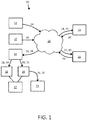
- the present disclosure describes a system 10 and related method for synchronized capture of image data and other non-image data by multiple network-connected capture devices.
- the system 10 includes a trigger 12, at least two capture devices 14, 16 (e.g., digital cameras), at least one controller 18, at least one synchronizer 20, and at least one compensator 22.
- the trigger 12 generates a trigger signal 24.
- the capture devices 14, 16 each switch from a respective idle mode to a respective recording mode upon receipt of the trigger signal 24 via a network 26.
- the capture devices 14, 16 each generate data packets 28, 30 when operated in the respective idle mode and the respective recording mode.
- the data packets 28, 30 each include sensor data indicative of a condition sensed by a sensor of the respective capture device 14, 16.
- the controller 18 saves data packets 28, 30 generated during the respective idle modes to a short-term memory 32, and save data packets 28, 30 generated during the respective recording modes to a long-term memory 34.
- the data packets 28, 30 are saved to the long-term memory 34 such that the data packets 28, 30 form respective saved data streams 36, 38 that can be retrieved and played back at a later time.
- the synchronizer 20 sends a sync signal 40 to the capture devices 14, 16 via the network 26.
- the compensator 22 determines respective delay periods 42, 44 between sending of the sync signal 40 by the synchronizer 20 (see arrow 46) and receipt of the sync signal 40 by each of the capture devices 14, 16 (see arrows 48, 50).
- the compensator 22 transfers from the short-term memory 32 to the long-term memory 34 any data packets 28, 30 generated during the respective delay periods 42, 44.
- the system 10 additionally includes a display 52 configured to retrieve recorded data streams 36, 38 from the long-term memory 34 and playback the same for a user.
- the trigger 12 receives a user input and generates the trigger signal 24 in response thereto.
- the trigger 12 can include a button, switch, or any other user input device to receive the user input.
- each of the capture devices 14, 16 is a digital camera capable of generating still image data and/or video image data.
- the capture devices 14, 16 each generate data packets 28, 30 that include image sensor data indicative of a light condition sensed by an image sensor of the respective capture device 14, 16.
- at least one of the capture devices 14, 16 generates data packets 28, 30 that include non-image sensor data.
- the at least one of the capture devices 14, 16 is a medical device (e.g., an insufflator, ventilator, EKG, MRI, etc.) and includes a sensor operable to generate sensor data indicative of a condition of the patient, an operating condition of the medical device (e.g., a speed of a fan included in the medical device, a temperature of the medical device, etc.), and/or an environmental condition (e.g., light, temperature, etc.).
- a medical device e.g., an insufflator, ventilator, EKG, MRI, etc.
- an environmental condition e.g., light, temperature, etc.
- the capture devices 14, 16 are each switchable between a power-off state and a power-on state. In the power-on state, the capture devices 14, 16 can each be operated in at least the idle mode and the recording mode. In the idle mode, the capture devices 14, 16 can continuously generate data packets 28, 30 to be stored by the controller 18 in the short-term memory 32. The data packets 28, 30 can be generated according to a predetermined capture rate, which can be period or non-periodic. In the illustrated embodiments, continuous generation of the data packets 28, 30 starts automatically when the capture devices 14, 16 begin operating in the respective idle modes. In other embodiments, the continuous generation of the data packets 28, 30 must first be initiated by a user. As will be discussed in more detail below, in some embodiments the capture devices 14, 16 can be operated at more than one recording mode.
- the number of capture devices 14, 16 included in the system 10 can vary depending on the particular application.
- the system 10 includes a first capture device 14 and a second capture device 16. In other embodiments, the system 10 can include many more than two capture devices 14, 16.
- the data packets 28, 30 generated by each of the capture devices 14, 16 include sensor data, as described above, and can also include embedded timestamps, metadata, and/or other data regarding the time, place, condition, etc., at which the data packets 28, 30 were generated.
- the data packets 28, 30 each include metadata indicating at least the time and operating mode (e.g., idle mode, recording mode, etc.) when the respective data packet 28, 30 was generated.
- the timestamps, metadata, and/or other data included in the data packets 28, 30 can be used by the controller 18, the compensator 22, and/or one or more other components during the saving, processing, and/or playback of recorded data streams 36, 38.
- FIG. 2 depicts data packets 28, 30 generated by the first and second capture devices 14, 16 of the system 10 of FIG. 1 after the data packets 28, 30 have been automatically saved to the short-term memory 32 or long-term memory 34 based on whether they were generated during the respect idle modes or the respective recording modes of the capture devices 14, 16.
- the data packets 28 generated by the first capture device 14 were saved to the short-term memory 32 until receipt of the sync signal 40 by the first capture device 14 at time t 1 (see arrow 48).
- the data packets 28 generated by the first capture device 14 were saved to the long-term memory 34, where they collectively formed a saved data stream 36 of the first capture device 14.
- the data packets 30 generated by the second capture device 16 were saved to the short-term memory 32 until receipt of the sync signal 40 by the second capture device 16 at time t 2 (see arrow 50).
- the data packets 30 generated by the second capture device 16 were saved to the long-term memory 34 where they collectively formed a saved data stream 38 of the second capture device 16.
- the controller 18 is a single component that receives the data packets 28, 30 from the capture devices 14, 16 via the network 26.
- the controller 18 and/or the short-term and long-term memories 32, 34 can be directly connected to the capture devices 14, 16. That is, storage of the data packets 28, 30 in one or both of the short-term and long-term memories 32, 34 can be done remotely via the network 26 (as shown in the illustrated embodiments), or it can be done locally.
- the short-term and long-term memories 32, 34 can each be one of various different types of memory devices, including, for example, a static RAM, dynamic RAM, flash memory, read only memory ROM (Read Only Memory), or another type of data storage medium.
- the short-term memory 32 provides only temporary storage and is automatically purged of data packets 28, 30 after a predetermined amount of time, whereas the long-term memory 34 provides permanent storage.
- the network 26 is a computer network such as the Internet or a subset of the Internet, a wide-area-network, local-area-network, private network of computing infrastructure, or other arrangement of interconnected computing equipment at the application, platform, or infrastructure level, or other cloud computing layers of abstraction.
- the synchronizer 20 sends the sync signal 40 to the capture devices 14, 16 as described above.
- the sync signal 40 can be similar to the data packets 28, 30 in that it can include embedded timestamps, metadata, and/or other data indicating the time at which the sync signal 40 was sent by the synchronizer 20, and/or other relevant information that can be used to perform the functionality described herein.
- the sync signal 40 and the information embedded therewith is used by the compensator 22 to perform the functionality described herein.
- the synchronizer 20 is disposed relative to the trigger 12, the capture devices 14, 16, and the network 26 such that respective delay periods 42, 44 between sending of the sync signal 40 and receipt of the sync signal 40 by each of the capture devices 14, 16 is identical to respective delay periods between sending of the trigger signal 24 and receipt of the trigger signal 24 by each of the capture devices 14, 16.
- the synchronizer 20 repeatedly sends the sync signal 40 to the capture devices 14, 16 via the network 26, and the compensator 22 repeatedly determines the respective delay periods 42, 44 of the capture devices 14, 16.
- the cycle of sending the sync signal 40 and determining the respective delay periods 42, 44 can be repeated throughout operation of the capture devices 14, 16 in the respective idle modes and recording modes.
- the repetition of the cycle can be periodic or non-periodic.
- the synchronizer 20 repeatedly sends the sync signal 40 in order to generate a common and aligned time basis that is used by one or more other components of the system 10 (e.g., the capture devices 14, 16, the compensator 22).
- the time basis can be periodic or non-periodic, and need not have any relation to real time.
- the time basis can be an arbitrary, regularly repeating signal. Additionally or alternatively, user initiated events can be used to form the time basis.
- the predetermined capture rate at which the data packets 28, 30 are generated is an integer multiple or divisor of a period rate at which the sync signal 40 is sent to the capture devices 14, 16.
- the system 10 includes a single synchronizer 20 that sends the same sync signal 40 to each of the capture devices 14, 16. In other embodiments, the system 10 includes more than one synchronizer 20. In the embodiment illustrated in FIG. 8 , for example, the system 10 includes a first synchronizer 20a and a second synchronizer 20b. Referring to FIG.
- the first synchronizer 20a can be a primary unit that sends a sync signal 40a to both of the capture devices 14, 16, and the second synchronizer 20b can be a secondary unit that sends a sync signal 40b to both of the capture devices 14, 16 only when first synchronizer 20a is unavailable (e.g., due to error, absence, power-off status, etc.).
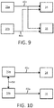
- the first and second synchronizers 20a, 20b can be configured such that the first synchronizer 20a sends a sync signal 40a to the fist capture device 14 and, in parallel, the second synchronizer 20b sends a sync signal 40b to the second capture device 16.
- the first and second synchronizers 20a, 20b can be synchronized with one another via a connection 54 therebetween.
- the compensator 22 is in communication with the short-term and long-term memories 32, 34. In the illustrated embodiments, the connection therebetween is direct. In other embodiments, the compensator 22 can be connected to the short-term and/or long-term memories 32, 34 via the network 26.
- the compensator 22 is also in direct and/or indirect communication with the synchronizer 20, which allows the compensator 22 to determine the time between sending of the sync signal 40 by the synchronizer 20 (see arrow 46) and receipt of the sync signal 40 by each of the capture devices 14, 16 (see arrows 48, 50), as discussed above.
- the compensator 22 determines respective delay periods 42, 44 and transfers from the short-term memory 32 to the long-term memory 34 any data packets 28, 30 generated during the respective delay periods 42, 44.
- the delay period 42 for the first capture device 14 is determined by the compensator 22 to be the difference between the time t 0 when the trigger signal 24 was sent by the trigger 12 (hereinafter the "trigger time t 0 ") and the time t 1 when the sync signal 40 was received by the first capture device 14 (see arrow 48).
- the delay period 44 for the second capture device 16 is calculated to be the difference between the trigger time t 0 and the time t 2 when the sync signal 40 was received by the second capture device 16 (see arrow 50).
- the data packets 28 0 , 30 0 , and 30 1 are shown to be the ones that will be transferred from the short-term memory 32 to the long-term memory 34 by the compensator 22, because they were generated during the respective delay periods 42, 44.
- the compensator 22 also removes data packets 28, 30 from ends of the saved data streams 36, 38 to provide saved data streams 36, 38 with predetermined numbers of data packets 36, 38. Additionally or alternatively, the compensator 22 can transfer data packets 36, 38 from the short-term memory 32 to the saved data streams 36, 38 to provide the saved data streams 36, 38 with a predetermined number of data packets 36, 38.
- the predetermined number of data packets 36, 38 in the resulting saved data streams 36, 68 can vary depending on the type of recording mode in which the capture devices 36, 38 are being operated.
- FIGS. 3-7 illustrate several different recording modes.
- the saved data stream 36 includes at least the data packet 28 generated at the trigger time t 0 .
- the saved data stream 36 additionally includes a single data packet 28 generated before the trigger time t 0 (i.e., data packet 28 -1 ) and a single data packet 28 generated after the trigger time t 0 (i.e., data packet 28 1 ).
- the saved data stream 36 additionally includes more than one data packet 28 generated before the trigger time t 0 (e.g., data packets 28 -1 and 28 -2 ).
- the saved data stream 36 additionally includes more than one data packet 28 generated after the trigger time t 0 (e.g., data packets 28 1 and 28 2 ).
- the saved data stream 36 additionally includes more than one data packet 28 generated before the trigger time t 0 (e.g., data packets 28- 1 and 28- 2 ) and more than one data packet 28 generated after the trigger time t 0 (e.g., data packets 28 1 and 28 2 ).
- the system 10 provides multiple network-connected capture devices 14, 16 configured to generate recorded data streams 36, 38 that start at least as early as the time t 0 that the trigger signal 24 is sent by the trigger 12 via the network 26.
- the system 10 enables perfectly synchronized viewing and/or playback of the recorded data streams 36, 38, and permits time-accurate switching between recorded data streams 36, 38 during playback (e.g., via display 52).
- the system 10 is able to account for the fact that delay times 42, 44 between the trigger 12 and each of the capture devices 14, 16 can change relative to one another over time due to changing conditions of the network 26.
- the system 10 also permits synchronization and correlation of image data with other non-image data captured during recording.
- the respective functionalities of the various components and sub-components of the system 10 can be implemented in various different ways, including use analog and/or digital hardware (e.g., counters, switches, logic devices, memory devices, programmable processors, non-transitory computer-readable storage mediums), software, firmware, or combinations thereof.
- the various components and sub-components of the system 10 can be specially constructed to perform the desired functionality, and/or can include one or more general purpose computers selectively configured to perform the desired functionality.
- the system 10 and/or the various components and subcomponents thereof can perform one or more of the functions described herein by executing software, which can be stored, for example, on a non-transitory computer-readable storage medium.
- the trigger 12 and the synchronizer 20 are described herein as being discrete components separate from one another, in some embodiments one or more of those components can be combined into a single component.
- the trigger 12 and the synchronizer 20 are described herein as being discrete components separate from one another, in some embodiments one or more of those components can be combined into a single component.
- another aspect of the present invention involves a method that includes the steps of: (i) connecting the trigger 12 and the synchronizer 20 to the capture devices 14, 16 via the network 26; (ii) sending the trigger signal 24 generated by the trigger 12 to the capture devices 14, 16 via the network 26 to thereby cause each of the capture devices 14, 16 to switch from the respective idle mode to the respective recording mode; (iii) saving data packets 28, 30 generated during the respective idle modes to a short-term memory 32, and saving data packets 28, 30 generated during the recording mode to a long-term memory such that the data packets form respective saved data streams 36, 38; (iv) sending a sync signal to the at least two capture devices via the network; (v) determining respective delay periods between sending of the sync signal by the synchronizer and receipt of the sync signal by each of the at least two capture devices; and (vi) transferring from the short-term memory to the long-term memory any data packets generated during the respective delay periods.
- the steps of the method can include various sub-steps, and/or various other steps in addition to the above-described steps.
- steps of the method are set forth in a particular order using alphanumeric labels, the labels are used merely for convenient identification of steps, and are not intended to imply, specify, or require a particular order of carrying out such steps.
- the method can include more or less steps than those discussed herein.
- determining is each used herein to refer to one or more actions and/or processes that can be implemented, for example, at least in part via a programmable processor or similar electronic computing device by manipulating and/or transforming data within processor memory into other data within processor memory.
- a system includes at least two capture devices, each switchable from a respective idle mode to a respective recording mode upon receipt of a trigger signal from a trigger via a network.
- a controller saves data packets generated by the capture devices during the respective idle modes to a short-term memory, and saves data packets generated during the respective recording modes to a long-term memory such that the data packets form respective saved data streams.
- the synchronizer sends a sync signal to the capture devices via the network.
- the compensator determines respective delay periods between sending of the sync signal by the synchronizer and receipt of the sync signal by each of the capture devices, and transfers from the short-term memory to the long-term memory any data packets generated during the respective delay period.
Landscapes
- Engineering & Computer Science (AREA)
- Multimedia (AREA)
- Signal Processing (AREA)
- Health & Medical Sciences (AREA)
- Medical Informatics (AREA)
- General Health & Medical Sciences (AREA)
- Epidemiology (AREA)
- Primary Health Care (AREA)
- Public Health (AREA)
- Databases & Information Systems (AREA)
- Radiology & Medical Imaging (AREA)
- Nuclear Medicine, Radiotherapy & Molecular Imaging (AREA)
- Television Signal Processing For Recording (AREA)
Abstract
Description
- The present disclosure generally relates to a system and related method for synchronized data capture by multiple capture devices. The present disclosure more particularly relates to a system and related method for synchronized capture of images and/or other non-image data by multiple network-connected capture devices.
- It is known provide a system with multiple digital cameras arranged to simultaneously capture a scene (e.g., a scene within a medical operating room) from multiple angles and/or multiple different scenes. A trigger can be used to aid in synchronizing the recording start and stop times of the multiple digital cameras. If the trigger is indirectly connected to the digital cameras (e.g., via one or more network connections), a trigger signal sent by the trigger might reach each of the digital cameras at a different real time, causing somewhat asynchronous recording start and stop times across the multiple digital cameras. This can be problematic if there is a need to have perfectly synchronized recordings from the multiple digital cameras, such as when there is a need to provide perfectly synchronized simultaneous playback of two or more of the recordings, and/or provide time-accurate switching between two or more of the recordings during playback.
- Known techniques for synchronizing recordings from multiple digital cameras are incapable of reliably providing recordings that start and stop at the exact times that start and stop signals are sent by the trigger, especially when the digital cameras and the trigger are connected via a network. Among other things, such techniques fail to account for the fact that respective network delay times between the trigger and each of the multiple digital cameras can change relative to one another over time due to changing conditions of the network. Known techniques also lack the ability to synchronize and correlate image recordings from multiple digital cameras with other non-image data captured during image recording.
- Aspects of the present invention are directed to these and other problems.
- According to an aspect of the present invention, a system is provided that includes a trigger, at least two capture devices, a controller, a short-term memory, a long-term memory, a synchronizer, and a compensator. The trigger is configured to generate a trigger signal. The at least two capture devices are each configured to switch from a respective idle mode to a respective recording mode upon receipt of the trigger signal via a network, and are each configured to generate data packets when operated in the respective idle mode and the respective recording mode. The data packets each include sensor data indicative of a condition sensed by a sensor of the respective capture device. The controller is configured to save data packets generated during the respective idle modes to a short-term memory, and configured to save data packets generated during the respective recording modes to a long-term memory such that the data packets form respective saved data streams. The synchronizer is configured to send a sync signal to the at least two capture devices via the network. The compensator configured to determine respective delay periods between sending of the sync signal by the synchronizer and receipt of the sync signal by each of the at least two capture devices. The compensator is further configured to transfer from the short-term memory to the long-term memory any data packets generated during the respective delay period.
- According to another aspect of the present invention, a method includes the steps of: (i) connecting a trigger and a synchronizer to at least two capture devices via a network, the at least two capture devices each configured to generate data packets when operated in a respective idle mode and a respective recording mode, the data packets each including sensor data indicative of a condition sensed by a sensor of the respective capture device; (ii) sending a trigger signal generated by the trigger to the at least two capture devices via the network to thereby cause each of the at least two capture devices to switch from the respective idle mode to the respective recording mode; (iii) saving data packets generated during the respective idle modes to a short-term memory, and saving data packets generated during the recording mode to a long-term memory such that the data packets form respective saved data streams; (iv) sending a sync signal to the at least two capture devices via the network; (v) determining respective delay periods between sending of the sync signal by the synchronizer and receipt of the sync signal by each of the at least two capture devices; and (vi) transferring from the short-term memory to the long-term memory any data packets generated during the respective delay periods.
- In addition to, or as an alternative to, one or more of the features described above, further aspects of the present invention can include one or more of the following features, individually or in combination:
- the trigger is configured to receive a user input and generate the trigger signal in response thereto;
- at least one of the at least two capture devices is a camera;
- the camera is at least one of a still image camera and a video image camera;
- the at least two digital cameras are each configured to generate data packets that include video image data;
- at least one of the at least two capture devices is configured to generate data packets that include non-image sensor data;
- at least one of the at least two capture devices is a medical device, and the medical device includes a sensor operable to generate sensor data indicative of a condition of a patient condition, an operating condition of the medical device, and/or an environmental condition;
- the at least two capture devices, when operated in the respective idle modes, continuously generate data packets;
- the at least two capture devices, when operated in the respective idle modes, continuously generate data packets according to a predetermined capture rate;
- the predetermined capture rate is an integer multiple or divisor of a period rate at which the sync signal is repetitively sent to the at least two capture devices;
- the data packets generated by the at least two capture devices further include metadata;
- the network is at least one the Internet, a wide-area-network, local-area-network, and a private network of computing infrastructure;
- the synchronizer has a time basis that is the same as, and aligned with, respective time bases of the at least two capture devices;
- the synchronizer is disposed relative to the trigger and the network such that respective delay periods between sending of the sync signal and receipt of the sync signal by each of the at least two capture devices is identical to respective delay periods between sending of the trigger signal and receipt of the trigger signal by each of the at least two capture devices;
- the synchronizer is configured to repeatedly send the sync signal to the at least two capture devices via the network, and the compensator is configured to repeatedly determine the respective delay periods of the at least two capture devices;
- the synchronizer is configured to repeatedly send the sync signal and the compensator is configured to repeatedly determine the respective delay periods according to a repetitive cycle;
- the synchronizer includes a first synchronizer unit and a second synchronizer unit, the first synchronizer unit configured to send the sync signal to the at least two capture devices, and the second synchronizer unit configured to send the sync signal to the at least two capture devices when the first synchronization unit is unavailable to do so;
- the synchronizer includes a first synchronizer unit and a second synchronizer unit, the first synchronizer unit configured to send the sync signal to a first capture device of the at least two capture devices, and the second synchronizer unit configured to send the sync signal to a second capture device of the at least two capture devices;
- the first synchronizer unit and the second synchronizer unit are synchronized with one another via a connection therebetween;
- the compensator is further configured to remove data packets from ends of the saved data streams to provide the saved data streams with predetermined numbers of data packets;
- the compensator is further configured to transfer from the short-term memory to the long-term memory a predetermined number of data packets generated before generation of the trigger signal by the trigger; and
- a display configured to retrieve saved data streams from the long-term memory and replay the saved data streams for a user;
- These and other aspects of the present invention will become apparent in light of the drawings and detailed description provided below.
-
-
FIG. 1 schematically illustrates an embodiment of the present system. -
FIG. 2 schematically illustrates data packets being saved to short-term and long-term memory. -
FIGS. 3-7 schematically illustrate recorded data streams generated using different recording modes. -
FIG. 8 schematically illustrates another embodiment of the present system. -
FIG. 9 schematically illustrates a connection between the synchronizer and the capture devices of the system ofFIG. 8 . -
FIG. 10 schematically illustrates an alternative connection between the synchronizer and the capture devices of the system ofFIG. 8 . - Referring to
FIG. 1 , the present disclosure describes asystem 10 and related method for synchronized capture of image data and other non-image data by multiple network-connected capture devices. - The
system 10 includes atrigger 12, at least twocapture devices 14, 16 (e.g., digital cameras), at least onecontroller 18, at least onesynchronizer 20, and at least onecompensator 22. Thetrigger 12 generates atrigger signal 24. Thecapture devices trigger signal 24 via anetwork 26. Thecapture devices data packets data packets respective capture device controller 18 savesdata packets term memory 32, and savedata packets term memory 34. Thedata packets term memory 34 such that thedata packets data streams 36, 38 that can be retrieved and played back at a later time. Thesynchronizer 20 sends async signal 40 to thecapture devices network 26. Referring toFIGS. 1 and2 , thecompensator 22 determinesrespective delay periods sync signal 40 by the synchronizer 20 (see arrow 46) and receipt of thesync signal 40 by each of thecapture devices 14, 16 (seearrows 48, 50). Thecompensator 22 transfers from the short-term memory 32 to the long-term memory 34 anydata packets respective delay periods system 10 additionally includes adisplay 52 configured to retrieve recordeddata streams 36, 38 from the long-term memory 34 and playback the same for a user. - The
trigger 12 receives a user input and generates thetrigger signal 24 in response thereto. Thetrigger 12 can include a button, switch, or any other user input device to receive the user input. - In the illustrated embodiments, each of the
capture devices capture devices data packets respective capture device capture devices data packets capture devices - The
capture devices capture devices capture devices data packets controller 18 in the short-term memory 32. Thedata packets data packets capture devices data packets capture devices - The number of
capture devices system 10 can vary depending on the particular application. In the illustrated embodiments, thesystem 10 includes afirst capture device 14 and asecond capture device 16. In other embodiments, thesystem 10 can include many more than twocapture devices - The
data packets capture devices data packets data packets respective data packet data packets controller 18, thecompensator 22, and/or one or more other components during the saving, processing, and/or playback of recorded data streams 36, 38. - As discussed above, the
controller 18 saves thedata packets capture devices term memory 32 and the long-term memory 34.FIG. 2 depictsdata packets second capture devices system 10 ofFIG. 1 after thedata packets term memory 32 or long-term memory 34 based on whether they were generated during the respect idle modes or the respective recording modes of thecapture devices data packets 28 generated by thefirst capture device 14 were saved to the short-term memory 32 until receipt of thesync signal 40 by thefirst capture device 14 at time t1 (see arrow 48). Thereafter, thedata packets 28 generated by thefirst capture device 14 were saved to the long-term memory 34, where they collectively formed a saveddata stream 36 of thefirst capture device 14. Similarly, it can be seen that thedata packets 30 generated by thesecond capture device 16 were saved to the short-term memory 32 until receipt of thesync signal 40 by thesecond capture device 16 at time t2 (see arrow 50). Thereafter, thedata packets 30 generated by thesecond capture device 16 were saved to the long-term memory 34 where they collectively formed a saved data stream 38 of thesecond capture device 16. - In the illustrated embodiments, the
controller 18 is a single component that receives thedata packets capture devices network 26. In other embodiments, thecontroller 18 and/or the short-term and long-term memories capture devices data packets term memories - The short-term and long-
term memories term memory 32 provides only temporary storage and is automatically purged ofdata packets term memory 34 provides permanent storage. - The
network 26 is a computer network such as the Internet or a subset of the Internet, a wide-area-network, local-area-network, private network of computing infrastructure, or other arrangement of interconnected computing equipment at the application, platform, or infrastructure level, or other cloud computing layers of abstraction. - The
synchronizer 20 sends thesync signal 40 to thecapture devices sync signal 40 can be similar to thedata packets sync signal 40 was sent by thesynchronizer 20, and/or other relevant information that can be used to perform the functionality described herein. Thesync signal 40 and the information embedded therewith is used by thecompensator 22 to perform the functionality described herein. - The
synchronizer 20 is disposed relative to thetrigger 12, thecapture devices network 26 such thatrespective delay periods sync signal 40 and receipt of thesync signal 40 by each of thecapture devices trigger signal 24 and receipt of thetrigger signal 24 by each of thecapture devices - In the illustrated embodiments, the
synchronizer 20 repeatedly sends thesync signal 40 to thecapture devices network 26, and thecompensator 22 repeatedly determines therespective delay periods capture devices sync signal 40 and determining therespective delay periods capture devices - In some embodiments, the
synchronizer 20 repeatedly sends thesync signal 40 in order to generate a common and aligned time basis that is used by one or more other components of the system 10 (e.g., thecapture devices data packets sync signal 40 is sent to thecapture devices - In the embodiment illustrated in
FIG. 1 , thesystem 10 includes asingle synchronizer 20 that sends thesame sync signal 40 to each of thecapture devices system 10 includes more than onesynchronizer 20. In the embodiment illustrated inFIG. 8 , for example, thesystem 10 includes afirst synchronizer 20a and asecond synchronizer 20b. Referring toFIG. 9 , in some such embodiments, thefirst synchronizer 20a can be a primary unit that sends async signal 40a to both of thecapture devices second synchronizer 20b can be a secondary unit that sends async signal 40b to both of thecapture devices first synchronizer 20a is unavailable (e.g., due to error, absence, power-off status, etc.). Referring toFIG. 10 , in other embodiments, the first andsecond synchronizers first synchronizer 20a sends async signal 40a to thefist capture device 14 and, in parallel, thesecond synchronizer 20b sends async signal 40b to thesecond capture device 16. In such embodiments, the first andsecond synchronizers connection 54 therebetween. - The
compensator 22 is in communication with the short-term and long-term memories compensator 22 can be connected to the short-term and/or long-term memories network 26. Thecompensator 22 is also in direct and/or indirect communication with thesynchronizer 20, which allows thecompensator 22 to determine the time between sending of thesync signal 40 by the synchronizer 20 (see arrow 46) and receipt of thesync signal 40 by each of thecapture devices 14, 16 (seearrows 48, 50), as discussed above. - As described above, the
compensator 22 determinesrespective delay periods term memory 32 to the long-term memory 34 anydata packets respective delay periods FIG. 2 , it can be seen that thedelay period 42 for thefirst capture device 14 is determined by thecompensator 22 to be the difference between the time t0 when thetrigger signal 24 was sent by the trigger 12 (hereinafter the "trigger time t0") and the time t1 when thesync signal 40 was received by the first capture device 14 (see arrow 48). Similarly, thedelay period 44 for thesecond capture device 16 is calculated to be the difference between the trigger time t0 and the time t2 when thesync signal 40 was received by the second capture device 16 (see arrow 50). Thedata packets term memory 32 to the long-term memory 34 by thecompensator 22, because they were generated during therespective delay periods - In some embodiments, the
compensator 22 also removesdata packets data streams 36, 38 to provide saveddata streams 36, 38 with predetermined numbers ofdata packets 36, 38. Additionally or alternatively, thecompensator 22 can transferdata packets 36, 38 from the short-term memory 32 to the saveddata streams 36, 38 to provide the saveddata streams 36, 38 with a predetermined number ofdata packets 36, 38. The predetermined number ofdata packets 36, 38 in the resulting saveddata streams 36, 68 can vary depending on the type of recording mode in which thecapture devices 36, 38 are being operated. -
FIGS. 3-7 illustrate several different recording modes. In each of the recording modes shown inFIGS. 3-7 , the saveddata stream 36 includes at least thedata packet 28 generated at the trigger time t0. In the recording mode shown inFIG. 4 , the saveddata stream 36 additionally includes asingle data packet 28 generated before the trigger time t0 (i.e., data packet 28-1) and asingle data packet 28 generated after the trigger time t0 (i.e., data packet 281). In the recording mode shown inFIG. 5 , the saveddata stream 36 additionally includes more than onedata packet 28 generated before the trigger time t0 (e.g.,data packets 28-1 and 28-2). In the recording mode shown inFIG. 6 , the saveddata stream 36 additionally includes more than onedata packet 28 generated after the trigger time t0 (e.g.,data packets 281 and 282). In the recording mode shown inFIG. 7 , the saveddata stream 36 additionally includes more than onedata packet 28 generated before the trigger time t0 (e.g., data packets 28-1 and 28-2) and more than onedata packet 28 generated after the trigger time t0 (e.g.,data packets 281 and 282). - The above-described functionalities of the
system 10 overcome the above-described problems with known synchronization techniques. Among other things, thesystem 10 provides multiple network-connectedcapture devices trigger signal 24 is sent by thetrigger 12 via thenetwork 26. Thesystem 10 enables perfectly synchronized viewing and/or playback of the recorded data streams 36, 38, and permits time-accurate switching between recorded data streams 36, 38 during playback (e.g., via display 52). Thesystem 10 is able to account for the fact thatdelay times trigger 12 and each of thecapture devices network 26. Thesystem 10 also permits synchronization and correlation of image data with other non-image data captured during recording. - The respective functionalities of the various components and sub-components of the
system 10 can be implemented in various different ways, including use analog and/or digital hardware (e.g., counters, switches, logic devices, memory devices, programmable processors, non-transitory computer-readable storage mediums), software, firmware, or combinations thereof. The various components and sub-components of thesystem 10 can be specially constructed to perform the desired functionality, and/or can include one or more general purpose computers selectively configured to perform the desired functionality. In some embodiments, thesystem 10 and/or the various components and subcomponents thereof can perform one or more of the functions described herein by executing software, which can be stored, for example, on a non-transitory computer-readable storage medium. In view of the present disclosure, a person having ordinary skill in the art would be able to assemble and/or adapt (e.g., construct, program) the various components and sub-components of thesystem 10 to perform the functionality described herein without undue experimentation. - Although some components of the
system 10 are described herein as being discrete components separate from one another, in some embodiments one or more of those components can be combined into a single component. For example, although thetrigger 12 and thesynchronizer 20 are described herein as being discrete components separate from one another, in some embodiments one or more of those components can be combined into a single component. - Referring to
FIG. 1 , another aspect of the present invention involves a method that includes the steps of: (i) connecting thetrigger 12 and thesynchronizer 20 to thecapture devices network 26; (ii) sending thetrigger signal 24 generated by thetrigger 12 to thecapture devices network 26 to thereby cause each of thecapture devices data packets term memory 32, and savingdata packets data streams 36, 38; (iv) sending a sync signal to the at least two capture devices via the network; (v) determining respective delay periods between sending of the sync signal by the synchronizer and receipt of the sync signal by each of the at least two capture devices; and (vi) transferring from the short-term memory to the long-term memory any data packets generated during the respective delay periods. - As will be apparent in view of the above-described functionality of the
system 10 and the various components thereof, the steps of the method can include various sub-steps, and/or various other steps in addition to the above-described steps. Although the steps of the method are set forth in a particular order using alphanumeric labels, the labels are used merely for convenient identification of steps, and are not intended to imply, specify, or require a particular order of carrying out such steps. Furthermore, in some embodiments, the method can include more or less steps than those discussed herein. - The terms "determining," "generating," and "recording," "sending," "saving," etc., and variations thereof, are each used herein to refer to one or more actions and/or processes that can be implemented, for example, at least in part via a programmable processor or similar electronic computing device by manipulating and/or transforming data within processor memory into other data within processor memory.
- The present disclosure describes aspects of the present invention with reference to the exemplary embodiments illustrated in the drawings; however, aspects of the present invention are not limited to the exemplary embodiments illustrated in the drawings. It will be apparent to those of ordinary skill in the art that aspects of the present invention include many more embodiments. Accordingly, aspects of the present invention are not to be restricted in light of the exemplary embodiments illustrated in the drawings. It will also be apparent to those of ordinary skill in the art that variations and modifications can be made without departing from the true scope of the present disclosure. For example, in some instances, one or more features disclosed in connection with one embodiment can be used alone or in combination with one or more features of one or more other embodiments.
- The present invention discloses in particular the aspects defined in the following clauses which form part of the present description.
- (1) A system, comprising a trigger configured to generate a trigger signal; at least two capture devices, each configured to switch from a respective idle mode to a respective recording mode upon receipt of the trigger signal via a network, and each configured to generate data packets when operated in the respective idle mode and the respective recording mode, the data packets each including sensor data indicative of a condition sensed by a sensor of the respective capture device; a controller configured to save data packets generated during the respective idle modes to a short-term memory, and configured to save data packets generated during the respective recording modes to a long-term memory such that the data packets form respective saved data streams; a synchronizer configured to send a sync signal to the at least two capture devices via the network; and a compensator configured to determine respective delay periods between sending of the sync signal by the synchronizer and receipt of the sync signal by each of the at least two capture devices, and configured to transfer from the short-term memory to the long-term memory any data packets generated during the respective delay periods.
- (2) The system of
clause 1, wherein the trigger is configured to receive a user input and generate the trigger signal in response thereto. - (3) The system of any of preceding clause, in
particular clause 1, wherein at least one of the at least two capture devices is a camera. - (4) The system of any of preceding clause, in particular clause 3, wherein the camera is at least one of a still image camera and a video image camera.
- (5) The system of any of preceding clause, in
particular clause 1, wherein the at least two capture devices are each configured to generate data packets that include video image data. - (6) The system of any of preceding clause, in
particular clause 1, wherein at least one of the at least two capture devices is configured to generate data packets that include non-image sensor data. - (7) The system of any of preceding clause, in
particular clause 6, wherein the at least one of the at least two capture devices that is configured to generate data packets that include non-image sensor data is a medical device, wherein the medical device includes a sensor operable to generate sensor data indicative of a condition of a patient condition, an operating condition of the medical device, and/or an environmental condition. - (8) The system of any of preceding clause, in
particular clause 1, wherein the at least two capture devices, when operated in the respective idle modes, continuously generate data packets. - (9) The system of any of preceding clause, in
particular clause 1, wherein the at least two capture devices, when operated in the respective idle modes, continuously generate data packets according to a predetermined capture rate. - (10) The system of any of preceding clause, in particular clause 9, wherein the predetermined capture rate is an integer multiple or divisor of a period rate at which the sync signal is repetitively sent to the at least two capture devices.
- (11) The system of any of preceding clause, in
particular clause 1, wherein the data packets generated by the at least two capture devices further include metadata. - (12) The system of any of preceding clause, in
particular clause 1, wherein the network is at least one the Internet, a wide-area-network, local-area-network, and a private network of computing infrastructure. - (13) The system of any of preceding clause, in
particular clause 1, wherein the synchronizer has a time basis that is the same as, and aligned with, respective time bases of the at least two capture devices. - (14) The system of any of preceding clause, in
particular clause 1, wherein the synchronizer is disposed relative to the trigger and the network such that respective delay periods between sending of the sync signal and receipt of the sync signal by each of the at least two capture devices is identical to respective delay periods between sending of the trigger signal and receipt of the trigger signal by each of the at least two capture devices. - (15) The system of any of preceding clause, in
particular clause 1, wherein the synchronizer is configured to repeatedly send the sync signal to the at least two capture devices via the network, and the compensator is configured to repeatedly determine the respective delay periods of the at least two capture devices. - (16) The system of any of preceding clause, in particular clause 15, wherein the synchronizer is configured to repeatedly send the sync signal and the compensator is configured to repeatedly determine the respective delay periods according to a repetitive cycle.
- (17) The system of any of preceding clause, in
particular clause 1, wherein the synchronizer includes a first synchronizer unit and a second synchronizer unit, the first synchronizer unit configured to send the sync signal to the at least two capture devices, and the second synchronizer unit configured to send the sync signal to the at least two capture devices when the first synchronization unit is unavailable to do so. - (18) The system of any of preceding clause, in
particular clause 1, wherein the synchronizer includes a first synchronizer unit and a second synchronizer unit, the first synchronizer unit configured to send the sync signal to a first capture device of the at least two capture devices, and the second synchronizer unit configured to send the sync signal to a second capture device of the at least two capture devices. - (19) The system of any of preceding clause, in
particular clause 18, wherein the first synchronizer unit and the second synchronizer unit are synchronized with one another via a connection therebetween. - (20) The system of any of preceding clause, in
particular clause 1, wherein the compensator is further configured to remove data packets from ends of the saved data streams to provide the saved data streams with predetermined numbers of data packets. - (21) The system of any of preceding clause, in
particular clause 1, wherein the compensator is further configured to transfer from the short-term memory to the long-term memory a predetermined number of data packets generated before generation of the trigger signal by the trigger. - (22) The system of any of preceding clause, in
particular clause 1, further comprising a display configured to retrieve saved data streams from the long-term memory and replay the saved data streams for a user. - (23) A method, comprising connecting a trigger and a synchronizer to at least two capture devices via a network, the at least two capture devices each configured to generate data packets when operated in a respective idle mode and a respective recording mode, the data packets each including sensor data indicative of a condition sensed by a sensor of the respective capture device; sending a trigger signal generated by the trigger to the at least two capture devices via the network to thereby cause each of the at least two capture devices to switch from the respective idle mode to the respective recording mode; saving data packets generated during the respective idle modes to a short-term memory, and saving data packets generated during the recording mode to a long-term memory such that the data packets form respective saved data streams; sending a sync signal to the at least two capture devices via the network; determining respective delay periods between sending of the sync signal by the synchronizer and receipt of the sync signal by each of the at least two capture devices; and transferring from the short-term memory to the long-term memory any data packets generated during the respective delay periods.
- There is disclosed a system includes at least two capture devices, each switchable from a respective idle mode to a respective recording mode upon receipt of a trigger signal from a trigger via a network. A controller saves data packets generated by the capture devices during the respective idle modes to a short-term memory, and saves data packets generated during the respective recording modes to a long-term memory such that the data packets form respective saved data streams. The synchronizer sends a sync signal to the capture devices via the network. The compensator determines respective delay periods between sending of the sync signal by the synchronizer and receipt of the sync signal by each of the capture devices, and transfers from the short-term memory to the long-term memory any data packets generated during the respective delay period.
Claims (15)
- A system, comprising:a trigger configured to generate a trigger signal;at least two capture devices, each configured to switch from a respective idle mode to a respective recording mode upon receipt of the trigger signal via a network, and each configured to generate data packets when operated in the respective idle mode and the respective recording mode, the data packets each including sensor data indicative of a condition sensed by a sensor of the respective capture device;a controller configured to save data packets generated during the respective idle modes to a short-term memory, and configured to save data packets generated during the respective recording modes to a long-term memory such that the data packets form respective saved data streams;a synchronizer configured to send a sync signal to the at least two capture devices via the network; anda compensator configured to determine respective delay periods between sending of the sync signal by the synchronizer and receipt of the sync signal by each of the at least two capture devices, and configured to transfer from the short-term memory to the long-term memory any data packets generated during the respective delay periods.
- The system of claim 1, wherein the trigger is configured to receive a user input and generate the trigger signal in response thereto.
- The system of any one of the preceding claims, wherein at least one of the at least two capture devices is a camera.
- The system of any one of the preceding claims, wherein the at least two capture devices are each configured to generate data packets that include video image data.
- The system of any one of the preceding claims, wherein at least one of the at least two capture devices is configured to generate data packets that include non-image sensor data; and
wherein the at least one of the at least two capture devices that is configured to generate data packets that include non-image sensor data is a medical device, wherein the medical device includes a sensor operable to generate sensor data indicative of a condition of a patient condition, an operating condition of the medical device, and/or an environmental condition. - The system of any one of the preceding claims, wherein the at least two capture devices, when operated in the respective idle modes, continuously generate data packets.
- The system of any one of the preceding claims, wherein the at least two capture devices, when operated in the respective idle modes, continuously generate data packets according to a predetermined capture rate; and
wherein the predetermined capture rate is an integer multiple or divisor of a period rate at which the sync signal is repetitively sent to the at least two capture devices. - The system of any one of the preceding claims, wherein the data packets generated by the at least two capture devices further include metadata.
- The system of any one of the preceding claims, wherein the synchronizer has a time basis that is the same as, and aligned with, respective time bases of the at least two capture devices.
- The system of any one of the preceding claims, wherein the synchronizer is disposed relative to the trigger and the network such that respective delay periods between sending of the sync signal and receipt of the sync signal by each of the at least two capture devices is identical to respective delay periods between sending of the trigger signal and receipt of the trigger signal by each of the at least two capture devices.
- The system of any one of the preceding claims, wherein the synchronizer is configured to repeatedly send the sync signal to the at least two capture devices via the network, and the compensator is configured to repeatedly determine the respective delay periods of the at least two capture devices.
- The system of any one of the preceding claims, wherein the synchronizer includes a first synchronizer unit and a second synchronizer unit, the first synchronizer unit configured to send the sync signal to the at least two capture devices, and the second synchronizer unit configured to send the sync signal to the at least two capture devices when the first synchronization unit is unavailable to do so.
- The system of any one of the preceding claims, wherein the synchronizer includes a first synchronizer unit and a second synchronizer unit connected thereto, the first synchronizer unit configured to send the sync signal to a first capture device of the at least two capture devices, and the second synchronizer unit configured to send the sync signal to a second capture device of the at least two capture devices.
- The system of any one of the preceding claims, wherein the compensator is further configured to remove data packets from ends of the saved data streams to provide the saved data streams with predetermined numbers of data packets.
- The system of any one of the preceding claims, wherein the compensator is further configured to transfer from the short-term memory to the long-term memory a predetermined number of data packets generated before generation of the trigger signal by the trigger.
Applications Claiming Priority (1)
| Application Number | Priority Date | Filing Date | Title |
|---|---|---|---|
| US15/344,116 US10560609B2 (en) | 2016-11-04 | 2016-11-04 | System and related method for synchronized capture of data by multiple network-connected capture devices |
Publications (2)
| Publication Number | Publication Date |
|---|---|
| EP3319313A1 true EP3319313A1 (en) | 2018-05-09 |
| EP3319313B1 EP3319313B1 (en) | 2021-07-07 |
Family
ID=60382029
Family Applications (1)
| Application Number | Title | Priority Date | Filing Date |
|---|---|---|---|
| EP17199990.7A Active EP3319313B1 (en) | 2016-11-04 | 2017-11-03 | System and related method for synchronized capture of data by multiple network-connected capture devices |
Country Status (2)
| Country | Link |
|---|---|
| US (1) | US10560609B2 (en) |
| EP (1) | EP3319313B1 (en) |
Cited By (1)
| Publication number | Priority date | Publication date | Assignee | Title |
|---|---|---|---|---|
| EP4190228A1 (en) | 2021-12-03 | 2023-06-07 | Erbe Elektromedizin GmbH | Device for tissue identification |
Families Citing this family (14)
| Publication number | Priority date | Publication date | Assignee | Title |
|---|---|---|---|---|
| US10911725B2 (en) * | 2017-03-09 | 2021-02-02 | Digital Ally, Inc. | System for automatically triggering a recording |
| US20180316844A1 (en) * | 2017-05-01 | 2018-11-01 | The United States of America, as represented by the Secretary of the Department of the Interior | System for 3-d mapping and measurement of fluid surface in dynamic motion |
| JP6369706B1 (en) * | 2017-12-27 | 2018-08-08 | 株式会社Medi Plus | Medical video processing system |
| US10931909B2 (en) * | 2018-09-18 | 2021-02-23 | Roku, Inc. | Wireless audio synchronization using a spread code |
| US10992336B2 (en) * | 2018-09-18 | 2021-04-27 | Roku, Inc. | Identifying audio characteristics of a room using a spread code |
| US10958301B2 (en) | 2018-09-18 | 2021-03-23 | Roku, Inc. | Audio synchronization of a dumb speaker and a smart speaker using a spread code |
| US10872240B2 (en) * | 2018-09-28 | 2020-12-22 | Opentv, Inc. | Systems and methods for generating media content |
| JP7276677B2 (en) * | 2019-02-18 | 2023-05-18 | カシオ計算機株式会社 | DATA ACQUISITION DEVICE, CONTROL METHOD AND CONTROL PROGRAM THEREOF, CONTROL DEVICE, DATA ACQUISITION DEVICE |
| CN110677623B (en) * | 2019-10-15 | 2021-09-10 | 北京百度网讯科技有限公司 | Data processing method, device, equipment and storage medium |
| EP3910644A1 (en) * | 2020-05-12 | 2021-11-17 | Koninklijke Philips N.V. | Quality control in medical imaging |
| EP4002389A1 (en) | 2020-11-17 | 2022-05-25 | TRUMPF Medizin Systeme GmbH + Co. KG | Operating room control and communication system |
| US11455873B2 (en) * | 2021-01-14 | 2022-09-27 | Google Llc | Buffered video recording for video cameras |
| CN114339067A (en) * | 2021-11-15 | 2022-04-12 | 华能国际电力股份有限公司上海石洞口第二电厂 | Multichannel image and video stream synchronization and distributed processing method and system based on 5G environment |
| US11950017B2 (en) | 2022-05-17 | 2024-04-02 | Digital Ally, Inc. | Redundant mobile video recording |
Citations (6)
| Publication number | Priority date | Publication date | Assignee | Title |
|---|---|---|---|---|
| WO2004038643A2 (en) * | 2002-10-25 | 2004-05-06 | Mcpheely Bernard M | Digital diagnosti video system for manufacturing and industrial process |
| US20060048025A1 (en) * | 2004-08-24 | 2006-03-02 | Kraft Foods Holdings, Inc. | Diagnostic data gathering apparatus and method |
| WO2007005408A2 (en) * | 2005-07-05 | 2007-01-11 | Massachusetts Eye & Ear Infirmary | Ambulatory monitors |
| US20090251601A1 (en) * | 2008-04-08 | 2009-10-08 | Baumer Optronic Gmbh | Method and device for synchronizing camera systems |
| JP2009296323A (en) * | 2008-06-05 | 2009-12-17 | Shimadzu Corp | Photographing apparatus |
| WO2011121951A1 (en) * | 2010-03-31 | 2011-10-06 | Sony Corporation | Camera system, signal delay amount adjusting method and program |
Family Cites Families (11)
| Publication number | Priority date | Publication date | Assignee | Title |
|---|---|---|---|---|
| US8539105B2 (en) | 2006-06-05 | 2013-09-17 | Stmicroelectronics, Inc. | System and method for synchronized content rendering in a multi-node network |
| US7805020B2 (en) | 2006-07-25 | 2010-09-28 | Itt Manufacturing Enterprises, Inc. | Motion compensated image registration for overlaid/fused video |
| GB2462101B (en) | 2008-07-24 | 2012-08-08 | Lifelines Ltd | A system for monitoring a patient's EEG output |
| CN102460562B (en) | 2009-05-22 | 2015-04-01 | 恩迪斯外科影像有限公司 | Multi-source medical imaging system |
| US8599235B2 (en) | 2009-07-27 | 2013-12-03 | Cisco Technology, Inc. | Automatic display latency measurement system for video conferencing |
| US20110275924A1 (en) * | 2010-05-07 | 2011-11-10 | Mclellan William | Method and System for Assimilating and Transmitting Medical Imaging and Associated Data to a Remote User |
| WO2011152489A1 (en) | 2010-06-03 | 2011-12-08 | オリンパスメディカルシステムズ株式会社 | Image recording system, and image recording method |
| US8488055B2 (en) * | 2010-09-30 | 2013-07-16 | Apple Inc. | Flash synchronization using image sensor interface timing signal |
| US8692864B2 (en) * | 2012-05-31 | 2014-04-08 | Ronald Angelo | Dynamic virtual multipoint video conference control unit |
| US9270708B2 (en) * | 2013-02-20 | 2016-02-23 | Apple Inc. | System and method of establishing communication between electronic devices |
| CN106559160A (en) * | 2015-09-30 | 2017-04-05 | 阿尔卡特朗讯 | Clock interface with propagation delay calibration function |
-
2016
- 2016-11-04 US US15/344,116 patent/US10560609B2/en active Active
-
2017
- 2017-11-03 EP EP17199990.7A patent/EP3319313B1/en active Active
Patent Citations (6)
| Publication number | Priority date | Publication date | Assignee | Title |
|---|---|---|---|---|
| WO2004038643A2 (en) * | 2002-10-25 | 2004-05-06 | Mcpheely Bernard M | Digital diagnosti video system for manufacturing and industrial process |
| US20060048025A1 (en) * | 2004-08-24 | 2006-03-02 | Kraft Foods Holdings, Inc. | Diagnostic data gathering apparatus and method |
| WO2007005408A2 (en) * | 2005-07-05 | 2007-01-11 | Massachusetts Eye & Ear Infirmary | Ambulatory monitors |
| US20090251601A1 (en) * | 2008-04-08 | 2009-10-08 | Baumer Optronic Gmbh | Method and device for synchronizing camera systems |
| JP2009296323A (en) * | 2008-06-05 | 2009-12-17 | Shimadzu Corp | Photographing apparatus |
| WO2011121951A1 (en) * | 2010-03-31 | 2011-10-06 | Sony Corporation | Camera system, signal delay amount adjusting method and program |
Cited By (2)
| Publication number | Priority date | Publication date | Assignee | Title |
|---|---|---|---|---|
| EP4190228A1 (en) | 2021-12-03 | 2023-06-07 | Erbe Elektromedizin GmbH | Device for tissue identification |
| US12551261B2 (en) | 2021-12-03 | 2026-02-17 | Erbe Elektromedizin Gmbh | Device and method for tissue identification |
Also Published As
| Publication number | Publication date |
|---|---|
| EP3319313B1 (en) | 2021-07-07 |
| US10560609B2 (en) | 2020-02-11 |
| US20180131844A1 (en) | 2018-05-10 |
Similar Documents
| Publication | Publication Date | Title |
|---|---|---|
| US10560609B2 (en) | System and related method for synchronized capture of data by multiple network-connected capture devices | |
| AU2007260845B2 (en) | Embedded appliance for multimedia capture | |
| JP5927795B2 (en) | Stereoscopic imaging system, recording control method, stereoscopic video playback system, and playback control method | |
| JP6372788B2 (en) | Imaging apparatus, imaging system, imaging method, and program | |
| CN114598786B (en) | Multi-camera frame synchronization control method and self-propelled equipment | |
| JP2019114296A (en) | System and device | |
| TW201245972A (en) | Collaborative image control | |
| CN101201965A (en) | Monitoring device and monitoring method | |
| CN104967891A (en) | Method and device for generating audio- video files | |
| JP2012204987A (en) | Imaging apparatus, synchronization control method, reproducing apparatus, and stereoscopic video imaging system | |
| US7619972B2 (en) | Video system | |
| WO2018030242A2 (en) | Multi-camera system, camera, processing method of camera, confirmation apparatus, and processing method of confirmation apparatus | |
| JP2015212876A (en) | Video playback system | |
| US12489971B2 (en) | Methods and systems for synchronizing image frames captured by a camera array | |
| CN204231519U (en) | Camera chain | |
| JP2016001837A (en) | Picture recorder and control method for picture recorder | |
| JP6355392B2 (en) | Recording apparatus, control method therefor, and storage medium | |
| TWM552716U (en) | Network switch control camera | |
| CN205901903U (en) | A video shooting system | |
| KR101165616B1 (en) | System for processing image of camera and apparatus for processing image and method for processing image of camera | |
| CN214480961U (en) | Remote video conference system | |
| JP2015186145A (en) | Image printing apparatus, image printing method, program, and image printing system | |
| CN110139117A (en) | Live data method for pushing and device | |
| JP2000261773A (en) | Information device control system | |
| JP2005176281A (en) | Control device, control method, and control program |
Legal Events
| Date | Code | Title | Description |
|---|---|---|---|
| PUAI | Public reference made under article 153(3) epc to a published international application that has entered the european phase |
Free format text: ORIGINAL CODE: 0009012 |
|
| STAA | Information on the status of an ep patent application or granted ep patent |
Free format text: STATUS: THE APPLICATION HAS BEEN PUBLISHED |
|
| AK | Designated contracting states |
Kind code of ref document: A1 Designated state(s): AL AT BE BG CH CY CZ DE DK EE ES FI FR GB GR HR HU IE IS IT LI LT LU LV MC MK MT NL NO PL PT RO RS SE SI SK SM TR |
|
| AX | Request for extension of the european patent |
Extension state: BA ME |
|
| STAA | Information on the status of an ep patent application or granted ep patent |
Free format text: STATUS: REQUEST FOR EXAMINATION WAS MADE |
|
| 17P | Request for examination filed |
Effective date: 20181109 |
|
| RBV | Designated contracting states (corrected) |
Designated state(s): AL AT BE BG CH CY CZ DE DK EE ES FI FR GB GR HR HU IE IS IT LI LT LU LV MC MK MT NL NO PL PT RO RS SE SI SK SM TR |
|
| STAA | Information on the status of an ep patent application or granted ep patent |
Free format text: STATUS: EXAMINATION IS IN PROGRESS |
|
| 17Q | First examination report despatched |
Effective date: 20191211 |
|
| GRAP | Despatch of communication of intention to grant a patent |
Free format text: ORIGINAL CODE: EPIDOSNIGR1 |
|
| STAA | Information on the status of an ep patent application or granted ep patent |
Free format text: STATUS: GRANT OF PATENT IS INTENDED |
|
| INTG | Intention to grant announced |
Effective date: 20201210 |
|
| RIN1 | Information on inventor provided before grant (corrected) |
Inventor name: LAU, STEPHEN |
|
| GRAJ | Information related to disapproval of communication of intention to grant by the applicant or resumption of examination proceedings by the epo deleted |
Free format text: ORIGINAL CODE: EPIDOSDIGR1 |
|
| STAA | Information on the status of an ep patent application or granted ep patent |
Free format text: STATUS: EXAMINATION IS IN PROGRESS |
|
| GRAP | Despatch of communication of intention to grant a patent |
Free format text: ORIGINAL CODE: EPIDOSNIGR1 |
|
| STAA | Information on the status of an ep patent application or granted ep patent |
Free format text: STATUS: GRANT OF PATENT IS INTENDED |
|
| INTC | Intention to grant announced (deleted) | ||
| INTG | Intention to grant announced |
Effective date: 20210318 |
|
| GRAS | Grant fee paid |
Free format text: ORIGINAL CODE: EPIDOSNIGR3 |
|
| GRAA | (expected) grant |
Free format text: ORIGINAL CODE: 0009210 |
|
| STAA | Information on the status of an ep patent application or granted ep patent |
Free format text: STATUS: THE PATENT HAS BEEN GRANTED |
|
| AK | Designated contracting states |
Kind code of ref document: B1 Designated state(s): AL AT BE BG CH CY CZ DE DK EE ES FI FR GB GR HR HU IE IS IT LI LT LU LV MC MK MT NL NO PL PT RO RS SE SI SK SM TR |
|
| REG | Reference to a national code |
Ref country code: GB Ref legal event code: FG4D |
|
| REG | Reference to a national code |
Ref country code: AT Ref legal event code: REF Ref document number: 1409749 Country of ref document: AT Kind code of ref document: T Effective date: 20210715 |
|
| REG | Reference to a national code |
Ref country code: DE Ref legal event code: R096 Ref document number: 602017041556 Country of ref document: DE |
|
| REG | Reference to a national code |
Ref country code: IE Ref legal event code: FG4D |
|
| REG | Reference to a national code |
Ref country code: LT Ref legal event code: MG9D |
|
| REG | Reference to a national code |
Ref country code: NL Ref legal event code: MP Effective date: 20210707 |
|
| REG | Reference to a national code |
Ref country code: AT Ref legal event code: MK05 Ref document number: 1409749 Country of ref document: AT Kind code of ref document: T Effective date: 20210707 |
|
| PG25 | Lapsed in a contracting state [announced via postgrant information from national office to epo] |
Ref country code: RS Free format text: LAPSE BECAUSE OF FAILURE TO SUBMIT A TRANSLATION OF THE DESCRIPTION OR TO PAY THE FEE WITHIN THE PRESCRIBED TIME-LIMIT Effective date: 20210707 Ref country code: SE Free format text: LAPSE BECAUSE OF FAILURE TO SUBMIT A TRANSLATION OF THE DESCRIPTION OR TO PAY THE FEE WITHIN THE PRESCRIBED TIME-LIMIT Effective date: 20210707 Ref country code: HR Free format text: LAPSE BECAUSE OF FAILURE TO SUBMIT A TRANSLATION OF THE DESCRIPTION OR TO PAY THE FEE WITHIN THE PRESCRIBED TIME-LIMIT Effective date: 20210707 Ref country code: PT Free format text: LAPSE BECAUSE OF FAILURE TO SUBMIT A TRANSLATION OF THE DESCRIPTION OR TO PAY THE FEE WITHIN THE PRESCRIBED TIME-LIMIT Effective date: 20211108 Ref country code: NO Free format text: LAPSE BECAUSE OF FAILURE TO SUBMIT A TRANSLATION OF THE DESCRIPTION OR TO PAY THE FEE WITHIN THE PRESCRIBED TIME-LIMIT Effective date: 20211007 Ref country code: NL Free format text: LAPSE BECAUSE OF FAILURE TO SUBMIT A TRANSLATION OF THE DESCRIPTION OR TO PAY THE FEE WITHIN THE PRESCRIBED TIME-LIMIT Effective date: 20210707 Ref country code: FI Free format text: LAPSE BECAUSE OF FAILURE TO SUBMIT A TRANSLATION OF THE DESCRIPTION OR TO PAY THE FEE WITHIN THE PRESCRIBED TIME-LIMIT Effective date: 20210707 Ref country code: ES Free format text: LAPSE BECAUSE OF FAILURE TO SUBMIT A TRANSLATION OF THE DESCRIPTION OR TO PAY THE FEE WITHIN THE PRESCRIBED TIME-LIMIT Effective date: 20210707 Ref country code: AT Free format text: LAPSE BECAUSE OF FAILURE TO SUBMIT A TRANSLATION OF THE DESCRIPTION OR TO PAY THE FEE WITHIN THE PRESCRIBED TIME-LIMIT Effective date: 20210707 Ref country code: BG Free format text: LAPSE BECAUSE OF FAILURE TO SUBMIT A TRANSLATION OF THE DESCRIPTION OR TO PAY THE FEE WITHIN THE PRESCRIBED TIME-LIMIT Effective date: 20211007 Ref country code: LT Free format text: LAPSE BECAUSE OF FAILURE TO SUBMIT A TRANSLATION OF THE DESCRIPTION OR TO PAY THE FEE WITHIN THE PRESCRIBED TIME-LIMIT Effective date: 20210707 |
|
| PG25 | Lapsed in a contracting state [announced via postgrant information from national office to epo] |
Ref country code: PL Free format text: LAPSE BECAUSE OF FAILURE TO SUBMIT A TRANSLATION OF THE DESCRIPTION OR TO PAY THE FEE WITHIN THE PRESCRIBED TIME-LIMIT Effective date: 20210707 Ref country code: LV Free format text: LAPSE BECAUSE OF FAILURE TO SUBMIT A TRANSLATION OF THE DESCRIPTION OR TO PAY THE FEE WITHIN THE PRESCRIBED TIME-LIMIT Effective date: 20210707 Ref country code: GR Free format text: LAPSE BECAUSE OF FAILURE TO SUBMIT A TRANSLATION OF THE DESCRIPTION OR TO PAY THE FEE WITHIN THE PRESCRIBED TIME-LIMIT Effective date: 20211008 |
|
| REG | Reference to a national code |
Ref country code: DE Ref legal event code: R097 Ref document number: 602017041556 Country of ref document: DE |
|
| PG25 | Lapsed in a contracting state [announced via postgrant information from national office to epo] |
Ref country code: DK Free format text: LAPSE BECAUSE OF FAILURE TO SUBMIT A TRANSLATION OF THE DESCRIPTION OR TO PAY THE FEE WITHIN THE PRESCRIBED TIME-LIMIT Effective date: 20210707 |
|
| PLBE | No opposition filed within time limit |
Free format text: ORIGINAL CODE: 0009261 |
|
| STAA | Information on the status of an ep patent application or granted ep patent |
Free format text: STATUS: NO OPPOSITION FILED WITHIN TIME LIMIT |
|
| PG25 | Lapsed in a contracting state [announced via postgrant information from national office to epo] |
Ref country code: SM Free format text: LAPSE BECAUSE OF FAILURE TO SUBMIT A TRANSLATION OF THE DESCRIPTION OR TO PAY THE FEE WITHIN THE PRESCRIBED TIME-LIMIT Effective date: 20210707 Ref country code: SK Free format text: LAPSE BECAUSE OF FAILURE TO SUBMIT A TRANSLATION OF THE DESCRIPTION OR TO PAY THE FEE WITHIN THE PRESCRIBED TIME-LIMIT Effective date: 20210707 Ref country code: RO Free format text: LAPSE BECAUSE OF FAILURE TO SUBMIT A TRANSLATION OF THE DESCRIPTION OR TO PAY THE FEE WITHIN THE PRESCRIBED TIME-LIMIT Effective date: 20210707 Ref country code: EE Free format text: LAPSE BECAUSE OF FAILURE TO SUBMIT A TRANSLATION OF THE DESCRIPTION OR TO PAY THE FEE WITHIN THE PRESCRIBED TIME-LIMIT Effective date: 20210707 Ref country code: CZ Free format text: LAPSE BECAUSE OF FAILURE TO SUBMIT A TRANSLATION OF THE DESCRIPTION OR TO PAY THE FEE WITHIN THE PRESCRIBED TIME-LIMIT Effective date: 20210707 Ref country code: AL Free format text: LAPSE BECAUSE OF FAILURE TO SUBMIT A TRANSLATION OF THE DESCRIPTION OR TO PAY THE FEE WITHIN THE PRESCRIBED TIME-LIMIT Effective date: 20210707 |
|
| 26N | No opposition filed |
Effective date: 20220408 |
|
| PG25 | Lapsed in a contracting state [announced via postgrant information from national office to epo] |
Ref country code: MC Free format text: LAPSE BECAUSE OF FAILURE TO SUBMIT A TRANSLATION OF THE DESCRIPTION OR TO PAY THE FEE WITHIN THE PRESCRIBED TIME-LIMIT Effective date: 20210707 |
|
| REG | Reference to a national code |
Ref country code: CH Ref legal event code: PL |
|
| PG25 | Lapsed in a contracting state [announced via postgrant information from national office to epo] |
Ref country code: LU Free format text: LAPSE BECAUSE OF NON-PAYMENT OF DUE FEES Effective date: 20211103 Ref country code: BE Free format text: LAPSE BECAUSE OF NON-PAYMENT OF DUE FEES Effective date: 20211130 |
|
| REG | Reference to a national code |
Ref country code: BE Ref legal event code: MM Effective date: 20211130 |
|
| PG25 | Lapsed in a contracting state [announced via postgrant information from national office to epo] |
Ref country code: IE Free format text: LAPSE BECAUSE OF NON-PAYMENT OF DUE FEES Effective date: 20211103 |
|
| PG25 | Lapsed in a contracting state [announced via postgrant information from national office to epo] |
Ref country code: HU Free format text: LAPSE BECAUSE OF FAILURE TO SUBMIT A TRANSLATION OF THE DESCRIPTION OR TO PAY THE FEE WITHIN THE PRESCRIBED TIME-LIMIT; INVALID AB INITIO Effective date: 20171103 |
|
| PG25 | Lapsed in a contracting state [announced via postgrant information from national office to epo] |
Ref country code: CY Free format text: LAPSE BECAUSE OF FAILURE TO SUBMIT A TRANSLATION OF THE DESCRIPTION OR TO PAY THE FEE WITHIN THE PRESCRIBED TIME-LIMIT Effective date: 20210707 |
|
| P01 | Opt-out of the competence of the unified patent court (upc) registered |
Effective date: 20230526 |
|
| PG25 | Lapsed in a contracting state [announced via postgrant information from national office to epo] |
Ref country code: LI Free format text: LAPSE BECAUSE OF NON-PAYMENT OF DUE FEES Effective date: 20220630 Ref country code: CH Free format text: LAPSE BECAUSE OF NON-PAYMENT OF DUE FEES Effective date: 20220630 |
|
| PG25 | Lapsed in a contracting state [announced via postgrant information from national office to epo] |
Ref country code: MK Free format text: LAPSE BECAUSE OF FAILURE TO SUBMIT A TRANSLATION OF THE DESCRIPTION OR TO PAY THE FEE WITHIN THE PRESCRIBED TIME-LIMIT Effective date: 20210707 |
|
| PG25 | Lapsed in a contracting state [announced via postgrant information from national office to epo] |
Ref country code: MT Free format text: LAPSE BECAUSE OF FAILURE TO SUBMIT A TRANSLATION OF THE DESCRIPTION OR TO PAY THE FEE WITHIN THE PRESCRIBED TIME-LIMIT Effective date: 20210707 |
|
| PG25 | Lapsed in a contracting state [announced via postgrant information from national office to epo] |
Ref country code: TR Free format text: LAPSE BECAUSE OF FAILURE TO SUBMIT A TRANSLATION OF THE DESCRIPTION OR TO PAY THE FEE WITHIN THE PRESCRIBED TIME-LIMIT Effective date: 20210707 |
|
| PGFP | Annual fee paid to national office [announced via postgrant information from national office to epo] |
Ref country code: DE Payment date: 20251126 Year of fee payment: 9 |
|
| PGFP | Annual fee paid to national office [announced via postgrant information from national office to epo] |
Ref country code: GB Payment date: 20251125 Year of fee payment: 9 |
|
| PGFP | Annual fee paid to national office [announced via postgrant information from national office to epo] |
Ref country code: IT Payment date: 20251121 Year of fee payment: 9 |
|
| PGFP | Annual fee paid to national office [announced via postgrant information from national office to epo] |
Ref country code: FR Payment date: 20251124 Year of fee payment: 9 |