EP3319226A1 - Servomotor drive device - Google Patents
Servomotor drive device Download PDFInfo
- Publication number
- EP3319226A1 EP3319226A1 EP15897184.6A EP15897184A EP3319226A1 EP 3319226 A1 EP3319226 A1 EP 3319226A1 EP 15897184 A EP15897184 A EP 15897184A EP 3319226 A1 EP3319226 A1 EP 3319226A1
- Authority
- EP
- European Patent Office
- Prior art keywords
- encoder
- servo amplifier
- control section
- initialization
- servo
- Prior art date
- Legal status (The legal status is an assumption and is not a legal conclusion. Google has not performed a legal analysis and makes no representation as to the accuracy of the status listed.)
- Granted
Links
Images


Classifications
-
- H—ELECTRICITY
- H02—GENERATION; CONVERSION OR DISTRIBUTION OF ELECTRIC POWER
- H02P—CONTROL OR REGULATION OF ELECTRIC MOTORS, ELECTRIC GENERATORS OR DYNAMO-ELECTRIC CONVERTERS; CONTROLLING TRANSFORMERS, REACTORS OR CHOKE COILS
- H02P1/00—Arrangements for starting electric motors or dynamo-electric converters
- H02P1/16—Arrangements for starting electric motors or dynamo-electric converters for starting dynamo-electric motors or dynamo-electric converters
-
- G—PHYSICS
- G01—MEASURING; TESTING
- G01D—MEASURING NOT SPECIALLY ADAPTED FOR A SPECIFIC VARIABLE; ARRANGEMENTS FOR MEASURING TWO OR MORE VARIABLES NOT COVERED IN A SINGLE OTHER SUBCLASS; TARIFF METERING APPARATUS; MEASURING OR TESTING NOT OTHERWISE PROVIDED FOR
- G01D5/00—Mechanical means for transferring the output of a sensing member; Means for converting the output of a sensing member to another variable where the form or nature of the sensing member does not constrain the means for converting; Transducers not specially adapted for a specific variable
- G01D5/12—Mechanical means for transferring the output of a sensing member; Means for converting the output of a sensing member to another variable where the form or nature of the sensing member does not constrain the means for converting; Transducers not specially adapted for a specific variable using electric or magnetic means
- G01D5/244—Mechanical means for transferring the output of a sensing member; Means for converting the output of a sensing member to another variable where the form or nature of the sensing member does not constrain the means for converting; Transducers not specially adapted for a specific variable using electric or magnetic means influencing characteristics of pulses or pulse trains; generating pulses or pulse trains
- G01D5/245—Mechanical means for transferring the output of a sensing member; Means for converting the output of a sensing member to another variable where the form or nature of the sensing member does not constrain the means for converting; Transducers not specially adapted for a specific variable using electric or magnetic means influencing characteristics of pulses or pulse trains; generating pulses or pulse trains using a variable number of pulses in a train
- G01D5/2451—Incremental encoders
-
- G—PHYSICS
- G05—CONTROLLING; REGULATING
- G05B—CONTROL OR REGULATING SYSTEMS IN GENERAL; FUNCTIONAL ELEMENTS OF SUCH SYSTEMS; MONITORING OR TESTING ARRANGEMENTS FOR SUCH SYSTEMS OR ELEMENTS
- G05B19/00—Program-control systems
- G05B19/02—Program-control systems electric
- G05B19/04—Program control other than numerical control, i.e. in sequence controllers or logic controllers
- G05B19/042—Program control other than numerical control, i.e. in sequence controllers or logic controllers using digital processors
- G05B19/0428—Safety, monitoring
-
- G—PHYSICS
- G05—CONTROLLING; REGULATING
- G05B—CONTROL OR REGULATING SYSTEMS IN GENERAL; FUNCTIONAL ELEMENTS OF SUCH SYSTEMS; MONITORING OR TESTING ARRANGEMENTS FOR SUCH SYSTEMS OR ELEMENTS
- G05B19/00—Program-control systems
- G05B19/02—Program-control systems electric
- G05B19/18—Numerical control [NC], i.e. automatically operating machines, in particular machine tools, e.g. in a manufacturing environment, so as to execute positioning, movement or co-ordinated operations by means of program data in numerical form
- G05B19/19—Numerical control [NC], i.e. automatically operating machines, in particular machine tools, e.g. in a manufacturing environment, so as to execute positioning, movement or co-ordinated operations by means of program data in numerical form characterised by positioning or contouring control systems, e.g. to control position from one programmed point to another or to control movement along a programmed continuous path
- G05B19/21—Numerical control [NC], i.e. automatically operating machines, in particular machine tools, e.g. in a manufacturing environment, so as to execute positioning, movement or co-ordinated operations by means of program data in numerical form characterised by positioning or contouring control systems, e.g. to control position from one programmed point to another or to control movement along a programmed continuous path using an incremental digital measuring device
-
- G—PHYSICS
- G05—CONTROLLING; REGULATING
- G05D—SYSTEMS FOR CONTROLLING OR REGULATING NON-ELECTRIC VARIABLES
- G05D3/00—Control of position or direction
- G05D3/12—Control of position or direction using feedback
-
- G—PHYSICS
- G07—CHECKING-DEVICES
- G07C—TIME OR ATTENDANCE REGISTERS; REGISTERING OR INDICATING THE WORKING OF MACHINES; GENERATING RANDOM NUMBERS; VOTING OR LOTTERY APPARATUS; ARRANGEMENTS, SYSTEMS OR APPARATUS FOR CHECKING NOT PROVIDED FOR ELSEWHERE
- G07C3/00—Registering or indicating the condition or the working of machines or other apparatus, other than vehicles
-
- H—ELECTRICITY
- H02—GENERATION; CONVERSION OR DISTRIBUTION OF ELECTRIC POWER
- H02P—CONTROL OR REGULATION OF ELECTRIC MOTORS, ELECTRIC GENERATORS OR DYNAMO-ELECTRIC CONVERTERS; CONTROLLING TRANSFORMERS, REACTORS OR CHOKE COILS
- H02P21/00—Arrangements or methods for the control of electric machines by vector control, e.g. by control of field orientation
- H02P21/14—Estimation or adaptation of machine parameters, e.g. flux, current or voltage
- H02P21/20—Estimation of torque
-
- H—ELECTRICITY
- H02—GENERATION; CONVERSION OR DISTRIBUTION OF ELECTRIC POWER
- H02P—CONTROL OR REGULATION OF ELECTRIC MOTORS, ELECTRIC GENERATORS OR DYNAMO-ELECTRIC CONVERTERS; CONTROLLING TRANSFORMERS, REACTORS OR CHOKE COILS
- H02P29/00—Arrangements for regulating or controlling electric motors, appropriate for both AC and DC motors
-
- G—PHYSICS
- G05—CONTROLLING; REGULATING
- G05B—CONTROL OR REGULATING SYSTEMS IN GENERAL; FUNCTIONAL ELEMENTS OF SUCH SYSTEMS; MONITORING OR TESTING ARRANGEMENTS FOR SUCH SYSTEMS OR ELEMENTS
- G05B19/00—Program-control systems
- G05B19/02—Program-control systems electric
- G05B19/18—Numerical control [NC], i.e. automatically operating machines, in particular machine tools, e.g. in a manufacturing environment, so as to execute positioning, movement or co-ordinated operations by means of program data in numerical form
- G05B19/406—Numerical control [NC], i.e. automatically operating machines, in particular machine tools, e.g. in a manufacturing environment, so as to execute positioning, movement or co-ordinated operations by means of program data in numerical form characterised by monitoring or safety
- G05B19/4062—Monitoring servoloop, e.g. overload of servomotor, loss of feedback or reference
-
- G—PHYSICS
- G05—CONTROLLING; REGULATING
- G05B—CONTROL OR REGULATING SYSTEMS IN GENERAL; FUNCTIONAL ELEMENTS OF SUCH SYSTEMS; MONITORING OR TESTING ARRANGEMENTS FOR SUCH SYSTEMS OR ELEMENTS
- G05B2219/00—Program-control systems
- G05B2219/30—Nc systems
- G05B2219/33—Director till display
- G05B2219/33218—Motor encoders, resolvers on common bus with drives, servo controllers
Definitions
- the present invention relates to a servomotor drive device with an improved recovery method when an error occurs with an encoder that detects rotation of the servomotor.
- Servomotors are used as drive devices for industrial machines and robots such as component mounters (refer to patent literature 1).
- the rotation of a servomotor is detected by an encoder, and in the servo amplifier, a count value (encoder value) of the encoder is compared to an instruction value so as to perform feedback control on the rotation of the servomotor.
- Patent literature 1 JP-A-2005-348475
- the encoder value may become an invalid value, and if the servomotor continues to be driven using this invalid encoder value, a large position deviation may occur with the driving target object, which may lead to a big problem such as mechanical interference.
- power is turned off and then on again.
- the present invention is a servomotor drive device including: an encoder configured to detect rotation of a servomotor that is a driving source for a driving target object; a servo amplifier configured to perform feedback control of the rotation of the servomotor based on a count value (hereinafter referred to as an "encoder value") of the encoder; and an amp control section configured to control operation of the servo amplifier, wherein the amp control section includes a function for sending an initialization instruction for initializing the encoder to the servo amplifier in a state of fixed cycle connection over a servo network between the servo amplifier and the encoder when an error occurs with the encoder, and the servo amplifier includes a function for performing initialization of the encoder without disconnecting the servo network when receiving the initialization instruction sent from the amp control section.
- an encoder configured to detect rotation of a servomotor that is a driving source for a driving target object
- a servo amplifier configured to perform feedback control of the rotation of the servo
- an initialization instruction for initializing the encoder is sent from the amp control section to the servo amplifier in a state of fixed cycle connection over a servo network between the amp control section and the servo amplifier so as to initialize the encoder, therefore, it is possible to quickly initialize the encoder in a state of fixed cycle connection over the servo network between the amp control section and the servo amplifier when an error occurs with the encoder, meaning that it is possible to recover from errors in a short time.
- the servo amplifier may include a function for maintaining a state in which it is possible to determine a state of initialization (pre-initialization, during initialization, initialization complete, initialization failed) of the encoder and an encoder value as encoder information
- the amp control section may include a function for obtaining the state of initialization and the encoder value of the encoder from the servo amplifier and sending the state of initialization of the encoder and the encoder value to an upper device control section. In this manner, it is possible to monitor the state of initialization and the encoder value of the encoder from an upper device control section.
- the servo amplifier and the amp control section may include a function for, in a case in which the encoder value is an invalid encoder value, prohibiting the servomotor from being turned on and controlled using the invalid encoder value. In this manner, in a case in which the encoder value is an invalid encoder value, it is possible to reliably prevent driving of the servomotor until recovery to a valid encoder value by normal completion of initialization of the encoder.
- multiple servomotors 11 are loaded as drive sources of driving target objects (in fig. 1 only one servomotor 11 is shown), and an absolute encoder 12 is provided for detecting a rotation angle (rotation position), rotation speed, rotation direction, and the like, of each servomotor 11.
- Each servomotor 11 performs feedback control to servo amplifier 13 based on a count value (hereinafter referred to as "encoder value") of encoder 12.
- encoder value a count value of encoder 12.
- feedback control may be performed by providing one servo amplifier 13 for each of the multiple servomotors 11, or by providing one multi-axis amplifier for multiple servomotors 11.
- servo amplifier 13 Items such as current control section 14 for controlling supply of electric current to servomotor 11 and servo network processing section 15 are provided in servo amplifier 13.
- Servo amplifier 13 is connected to amp control section 17 via the servo network.
- Items such as servo network processing section 16, and command torque calculating section 18 are provided in amp control section 17.
- Amp control section 17 is connected to upper device control section 21 via a servo network.
- amp control section 17 by performing the amp control section control program of fig. 2 described later, when an error occurs with encoder 12, sends an initialization instruction for initializing encoder 23 to servo amplifier 13 in a state of fixed cycle connection over a servo network between amp control section 17 and servo amplifier 13.
- servo amplifier 13 by performing the servo amplifier control program of fig. 3 described later, when the initialization command sent from amp control section 17 is received, performs initialization of encoder 12 without disconnecting the servo network. Further, servo amplifier 13 memorizes and saves in a rewritable non-volatile memory (not shown) the state of initialization (pre-initialization, during initialization, initialization complete, initialization failed) and the encoder value of encoder 12, and in a case in which the encoder value is an invalid encoder value, prohibits the servo power from being turned on to servomotor 11 and control being performed using the invalid encoder value.
- amp control section 17 obtains the state of initialization and the encoder value of encoder 12 from servo amplifier 13 and sends the state of initialization and the encoder value of encoder 12 to upper device control section 21.
- step 101 an initialization command for initializing encoder 12 is sent to servo amplifier 13 in a state a fixed cycle connection over a servo network between amp control section 17 and servo amplifier 13.
- step 101 whether it is possible to reinitialize encoder 12 (whether encoder 12 supports reinitialization) is asked of servo amplifier 13.
- step 102 after standing by until the transmission cycle of the servo network, continuing to step 103, the servo network information is updated.
- the command torque calculated in command torque calculating section 18 is set in the servo network send data, and the state of initialization (one state out of pre-initialization, during initialization, initialization complete, initialization failed) and the encoder value of encoder 12 are obtained as encoder information from servo amplifier 13 via the servo network.
- the encoder value becomes an invalid encoder value for pre-initialization and initialization failed.
- step 14 it is determined whether an error has occurred with encoder 12, and if an error has not occurred, continuing to step 105, a command value is calculated in command torque calculating section 18, and processing returns to step 102.
- step 14 it is determined whether an error has occurred with encoder 12, and if an error has not occurred, continuing to step 105, a command value is calculated in command torque calculating section 18, and processing returns to step 102.
- step 106 when an error occurs with encoder 12, continuing to step 106, upper device control section 21 is notified of the error of encoder 12 from amp control section 17. Then, continuing to step 107, it is determined whether reinitialization of encoder 12 is possible, and if reinitialization of encoder 12 is not possible, processing returns to step 101, and the above processing is repeated.
- step 108 processing stands by until a recovery instruction is received from upper device control section 21.
- step 109 processing continues to step 109, and reinitialization of encoder 12 is instructed to servo amplifier 13.
- step 110 after standing by until the transmission cycle of the servo network, continuing to step 111, the servo network information is updated.
- the reinitialization completion state of encoder 12 is checked via the servo network.
- step 112 it is determined whether reinitialization of encoder 12 is complete, and processing of updating the servo network information is repeated by the servo network transmission cycle until reinitialization of encoder 12 is complete.
- processing returns to step 102 and is repeated from there.
- the servo amplifier control program of fig. 3 is performed while power is turned on to servo amplifier 13.
- initialization of encoder 12 is performed.
- step 202 processing stands by until receipt of a trigger of the updating cycle of encoder 12.
- An internal trigger for encoder 12 to perform updating is issued in a regular cycle.
- encoder 12 is in a state of initialization complete.
- encoder information encoder value, encoder error information, and so on is obtained from encoder 12.
- step 204 data exchange is performed with servo network processing section 15 of servo amplifier 13.
- data that current control section 14 of servo amplifier 13 obtains from servo network processing section 15 is a command torque
- data that servo network processing section 15 of servo amplifier 13 obtains from current control section 14 is an encoder value, information of errors that are occurring (encoder errors and the like), and the state of initialization of encoder 12 (pre-initialization, during initialization, initialization complete).
- step 205 it is determined whether an error has occurred with encoder 12, and if an error has not occurred with encoder 12, continuing to step 206, a current value is calculated from the command torque, and, continuing to step 207, the current value calculated from the command torque is output to servomotor 11, then, returning to step 202, the above processing is repeated.
- step 205 while power is turned on to servo amplifier 13, if an error has not occurred with encoder 12, processing of converting the command torque is to a current value in the update cycle of encoder 12 and outputting to servomotor 11 is repeated.
- step 208 the output of current for controlling the servomotor is stopped, and in step 209, an error state is set.
- an error state is set.
- the state of initialization of encoder 12 transitions to a pre-initialization state.
- step 210 processing stands by until an encoder 12 reinitialization instruction is received from amp control section 17, and when the reinitialization instruction is received, returning to step 201, the above processing is repeated.
- servo power is prevented from being turned on to servomotor 11 until recovery to a valid encoder value by normal completion of initialization of encoder 12.
- an initialization instruction for initializing encoder 23 is sent from amp control section 17 to servo amplifier 13 in a state of fixed cycle connection over a servo network between amp control section 17 and servo amplifier 11 so as to initialize encoder 12, therefore, it is possible to quickly initialize encoder 12 in a state of fixed cycle connection over the servo network between amp control section 17 and servo amplifier 13 when an error occurs with encoder 12, meaning that it is possible to recover from errors in a short time.
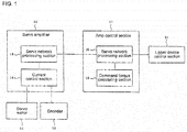
- 11 servomotor; 12: encoder; 13: servo amplifier; 14: current control section; 15, 16: servo network processing section; 17: amp control section; 18: command torque calculating section; 21: upper device control section
Landscapes
- Engineering & Computer Science (AREA)
- Physics & Mathematics (AREA)
- General Physics & Mathematics (AREA)
- Power Engineering (AREA)
- Automation & Control Theory (AREA)
- Human Computer Interaction (AREA)
- Manufacturing & Machinery (AREA)
- Control Of Electric Motors In General (AREA)
- Control Of Position Or Direction (AREA)
- Safety Devices In Control Systems (AREA)
Abstract
Description
- The present invention relates to a servomotor drive device with an improved recovery method when an error occurs with an encoder that detects rotation of the servomotor.
- Servomotors are used as drive devices for industrial machines and robots such as component mounters (refer to patent literature 1). Generally, the rotation of a servomotor is detected by an encoder, and in the servo amplifier, a count value (encoder value) of the encoder is compared to an instruction value so as to perform feedback control on the rotation of the servomotor.
- Patent literature 1:
JP-A-2005-348475 - However, if some kind of error occurs during operation of the encoder, the encoder value may become an invalid value, and if the servomotor continues to be driven using this invalid encoder value, a large position deviation may occur with the driving target object, which may lead to a big problem such as mechanical interference. Thus, when an encoder error occurs, power is turned off and then on again.
- But, if the power is turned off, the supply of power to the amp control section of the servo amplifier is also cut, which means that, after power is turned on again, it is necessary to re-establish communication between the upper device control section and the amp control section. As a result, when an encoder error occurs, it takes time until recovery to a state in which it is possible to start driving the servomotor.
- To solve the above problems, the present invention is a servomotor drive device including: an encoder configured to detect rotation of a servomotor that is a driving source for a driving target object; a servo amplifier configured to perform feedback control of the rotation of the servomotor based on a count value (hereinafter referred to as an "encoder value") of the encoder; and an amp control section configured to control operation of the servo amplifier, wherein the amp control section includes a function for sending an initialization instruction for initializing the encoder to the servo amplifier in a state of fixed cycle connection over a servo network between the servo amplifier and the encoder when an error occurs with the encoder, and the servo amplifier includes a function for performing initialization of the encoder without disconnecting the servo network when receiving the initialization instruction sent from the amp control section.
- With this configuration, when an error occurs with the encoder, an initialization instruction for initializing the encoder is sent from the amp control section to the servo amplifier in a state of fixed cycle connection over a servo network between the amp control section and the servo amplifier so as to initialize the encoder, therefore, it is possible to quickly initialize the encoder in a state of fixed cycle connection over the servo network between the amp control section and the servo amplifier when an error occurs with the encoder, meaning that it is possible to recover from errors in a short time.
- In this case, the servo amplifier may include a function for maintaining a state in which it is possible to determine a state of initialization (pre-initialization, during initialization, initialization complete, initialization failed) of the encoder and an encoder value as encoder information, and the amp control section may include a function for obtaining the state of initialization and the encoder value of the encoder from the servo amplifier and sending the state of initialization of the encoder and the encoder value to an upper device control section. In this manner, it is possible to monitor the state of initialization and the encoder value of the encoder from an upper device control section.
- Further, the servo amplifier and the amp control section may include a function for, in a case in which the encoder value is an invalid encoder value, prohibiting the servomotor from being turned on and controlled using the invalid encoder value. In this manner, in a case in which the encoder value is an invalid encoder value, it is possible to reliably prevent driving of the servomotor until recovery to a valid encoder value by normal completion of initialization of the encoder.
-
- [
Fig. 1 ]
Fig. 1 is a block diagram showing the configuration of a servomotor drive device in an embodiment of the present invention. - [
Fig. 2 ]
Fig. 2 is a flowchart showing the flow of processing of an amp control section control program. - [
Fig. 3 ]
Fig. 3 is a flowchart showing the flow of processing of a servo amplifier control program. - An embodiment of the invention is described below. First, the configuration of a servomotor drive device is described based on
fig. 1 . - In an industrial machine such as a component mounter,
multiple servomotors 11 are loaded as drive sources of driving target objects (infig. 1 only oneservomotor 11 is shown), and anabsolute encoder 12 is provided for detecting a rotation angle (rotation position), rotation speed, rotation direction, and the like, of eachservomotor 11. Eachservomotor 11 performs feedback control toservo amplifier 13 based on a count value (hereinafter referred to as "encoder value") ofencoder 12. In this case, feedback control may be performed by providing oneservo amplifier 13 for each of themultiple servomotors 11, or by providing one multi-axis amplifier formultiple servomotors 11. - Items such as
current control section 14 for controlling supply of electric current toservomotor 11 and servonetwork processing section 15 are provided inservo amplifier 13.Servo amplifier 13 is connected toamp control section 17 via the servo network. Items such as servonetwork processing section 16, and commandtorque calculating section 18 are provided inamp control section 17.Amp control section 17 is connected to upperdevice control section 21 via a servo network. - Here,
amp control section 17, by performing the amp control section control program offig. 2 described later, when an error occurs withencoder 12, sends an initialization instruction for initializing encoder 23 toservo amplifier 13 in a state of fixed cycle connection over a servo network betweenamp control section 17 andservo amplifier 13. - On the other hand,
servo amplifier 13, by performing the servo amplifier control program offig. 3 described later, when the initialization command sent fromamp control section 17 is received, performs initialization ofencoder 12 without disconnecting the servo network. Further,servo amplifier 13 memorizes and saves in a rewritable non-volatile memory (not shown) the state of initialization (pre-initialization, during initialization, initialization complete, initialization failed) and the encoder value ofencoder 12, and in a case in which the encoder value is an invalid encoder value, prohibits the servo power from being turned on toservomotor 11 and control being performed using the invalid encoder value. - On the other hand,
amp control section 17 obtains the state of initialization and the encoder value ofencoder 12 fromservo amplifier 13 and sends the state of initialization and the encoder value ofencoder 12 to upperdevice control section 21. - Described below are the processing contents of the amp control section control program of
fig. 2 performed byamp control section 17. The amp control section control program offig. 2 is performed while power is turned on toamp control section 17. When the program is started, first, instep 101, an initialization command for initializingencoder 12 is sent toservo amplifier 13 in a state a fixed cycle connection over a servo network betweenamp control section 17 andservo amplifier 13. Here, whether it is possible to reinitialize encoder 12 (whetherencoder 12 supports reinitialization) is asked ofservo amplifier 13. - In
step 102, after standing by until the transmission cycle of the servo network, continuing to step 103, the servo network information is updated. Here, the command torque calculated in commandtorque calculating section 18 is set in the servo network send data, and the state of initialization (one state out of pre-initialization, during initialization, initialization complete, initialization failed) and the encoder value ofencoder 12 are obtained as encoder information fromservo amplifier 13 via the servo network. The encoder value becomes an invalid encoder value for pre-initialization and initialization failed. - Then, continuing to step 14, it is determined whether an error has occurred with
encoder 12, and if an error has not occurred, continuing to step 105, a command value is calculated in commandtorque calculating section 18, and processing returns tostep 102. By this, while power is on toamp control section 17, if no error has occurred forencoder 12, updating of servo network information over the servo network transmission cycle and calculating of command torque are repeated. - Then, when an error occurs with
encoder 12, continuing to step 106, upperdevice control section 21 is notified of the error ofencoder 12 fromamp control section 17. Then, continuing to step 107, it is determined whether reinitialization ofencoder 12 is possible, and if reinitialization ofencoder 12 is not possible, processing returns tostep 101, and the above processing is repeated. - In contrast, if reinitialization of
encoder 12 is possible, continuing to step 108, processing stands by until a recovery instruction is received from upperdevice control section 21. When the recover instruction is received from upperdevice control section 21, processing continues to step 109, and reinitialization ofencoder 12 is instructed toservo amplifier 13. - Then, continuing to step 110, after standing by until the transmission cycle of the servo network, continuing to step 111, the servo network information is updated. Here, the reinitialization completion state of
encoder 12 is checked via the servo network. Instep 112, it is determined whether reinitialization ofencoder 12 is complete, and processing of updating the servo network information is repeated by the servo network transmission cycle until reinitialization ofencoder 12 is complete. Then, when reinitialization ofencoder 12 is complete, processing returns tostep 102 and is repeated from there. By such processing, in a case in which an encoder value is an invalid encoder value due to an error ofencoder 12, servo power is prevented from being turned on toservomotor 11 until recovery to a valid encoder value by normal completion of initialization ofencoder 12. - Described next are the processing contents of the servo amplifier control program of
fig. 3 performed byservo amplifier 13. The servo amplifier control program offig. 3 is performed while power is turned on toservo amplifier 13. When the program is started, first, instep 201, initialization ofencoder 12 is performed. - Then, in
step 202, processing stands by until receipt of a trigger of the updating cycle ofencoder 12. An internal trigger forencoder 12 to perform updating is issued in a regular cycle. After receipt of the trigger,encoder 12 is in a state of initialization complete. When the trigger is received, continuing to step 203, encoder information (encoder value, encoder error information, and so on) is obtained fromencoder 12. - Then, continuing to step 204, data exchange is performed with servo
network processing section 15 ofservo amplifier 13. Here, data thatcurrent control section 14 ofservo amplifier 13 obtains from servonetwork processing section 15 is a command torque, and on the other hand, data that servonetwork processing section 15 ofservo amplifier 13 obtains fromcurrent control section 14 is an encoder value, information of errors that are occurring (encoder errors and the like), and the state of initialization of encoder 12 (pre-initialization, during initialization, initialization complete). - Then, in
step 205, it is determined whether an error has occurred withencoder 12, and if an error has not occurred withencoder 12, continuing to step 206, a current value is calculated from the command torque, and, continuing to step 207, the current value calculated from the command torque is output toservomotor 11, then, returning to step 202, the above processing is repeated. By this, while power is turned on toservo amplifier 13, if an error has not occurred withencoder 12, processing of converting the command torque is to a current value in the update cycle ofencoder 12 and outputting toservomotor 11 is repeated. - Then, when an error occurs with
encoder 12, continuing to step 208, the output of current for controlling the servomotor is stopped, and instep 209, an error state is set. By this, when an error occurs withencoder 12, the state of initialization ofencoder 12 transitions to a pre-initialization state. Then, continuing to step 210, processing stands by until anencoder 12 reinitialization instruction is received fromamp control section 17, and when the reinitialization instruction is received, returning to step 201, the above processing is repeated. By such processing, in a case in which an encoder value is an invalid encoder value due to an error ofencoder 12, servo power is prevented from being turned on toservomotor 11 until recovery to a valid encoder value by normal completion of initialization ofencoder 12. - According to an embodiment described above, when an error occurs with
encoder 12, an initialization instruction for initializing encoder 23 is sent fromamp control section 17 toservo amplifier 13 in a state of fixed cycle connection over a servo network betweenamp control section 17 andservo amplifier 11 so as to initializeencoder 12, therefore, it is possible to quickly initializeencoder 12 in a state of fixed cycle connection over the servo network betweenamp control section 17 andservo amplifier 13 when an error occurs withencoder 12, meaning that it is possible to recover from errors in a short time. - Note that, the present invention is not limited to the embodiments described above and it goes without saying that various embodiments with changes that do not extend beyond the scope of the invention are possible, such as that suitable changes may be made to the configuration of
servo amplifier 13 andamp control section 17. - 11: servomotor; 12: encoder; 13: servo amplifier; 14: current control section; 15, 16: servo network processing section; 17: amp control section; 18: command torque calculating section; 21: upper device control section
Claims (3)
- A servomotor drive device comprising:an encoder configured to detect rotation of a servomotor that is a driving source for a driving target object;a servo amplifier configured to perform feedback control of the rotation of the servomotor based on a count value (hereinafter referred to as an "encoder value") of the encoder; andan amp control section configured to control operation of the servo amplifier,
whereinthe amp control section includes a function for sending an initialization instruction for initializing the encoder to the servo amplifier in a state of fixed cycle connection over a servo network between the servo amplifier and the encoder when an error occurs with the encoder, andthe servo amplifier includes a function for performing initialization of the encoder without disconnecting the servo network when receiving the initialization instruction sent from the amp control section. - The servomotor drive device according to claim 1, wherein
the servo amplifier includes a function for maintaining a state in which it is possible to determine a state of initialization of the encoder and an encoder value as encoder information, and
the amp control section includes a function for obtaining the state of initialization and the encoder value of the encoder from the servo amplifier and sending the state of initialization of the encoder and the encoder value to an upper device control section. - The servomotor drive device according to claim 2, wherein
the servo amplifier and the amp control section include a function for, in a case in which the encoder value is an invalid encoder value, prohibiting the servomotor from being turned on and controlled using the invalid encoder value.
Applications Claiming Priority (1)
| Application Number | Priority Date | Filing Date | Title |
|---|---|---|---|
| PCT/JP2015/069125 WO2017002257A1 (en) | 2015-07-02 | 2015-07-02 | Servomotor drive device |
Publications (3)
| Publication Number | Publication Date |
|---|---|
| EP3319226A1 true EP3319226A1 (en) | 2018-05-09 |
| EP3319226A4 EP3319226A4 (en) | 2018-05-30 |
| EP3319226B1 EP3319226B1 (en) | 2021-04-28 |
Family
ID=57609379
Family Applications (1)
| Application Number | Title | Priority Date | Filing Date |
|---|---|---|---|
| EP15897184.6A Active EP3319226B1 (en) | 2015-07-02 | 2015-07-02 | Servomotor drive device |
Country Status (5)
| Country | Link |
|---|---|
| US (1) | US10491142B2 (en) |
| EP (1) | EP3319226B1 (en) |
| JP (1) | JP6612866B2 (en) |
| CN (1) | CN107820673B (en) |
| WO (1) | WO2017002257A1 (en) |
Families Citing this family (1)
| Publication number | Priority date | Publication date | Assignee | Title |
|---|---|---|---|---|
| JP2023152076A (en) * | 2022-04-01 | 2023-10-16 | オムロン株式会社 | Control device |
Family Cites Families (10)
| Publication number | Priority date | Publication date | Assignee | Title |
|---|---|---|---|---|
| US4988935A (en) * | 1989-05-24 | 1991-01-29 | Universal Instruments Corporation | Advanced digital motion control |
| US5331232A (en) * | 1992-05-14 | 1994-07-19 | Storage Technology Corporation | On-the-fly position calibration of a robotic arm |
| JP2005348475A (en) * | 2004-06-01 | 2005-12-15 | Matsushita Electric Ind Co Ltd | Electric motor drive |
| JP2006003307A (en) * | 2004-06-21 | 2006-01-05 | Mitsutoyo Corp | Encoder, and signal regulation method therefor |
| CN101263499B (en) * | 2005-07-11 | 2013-03-27 | 布鲁克斯自动化公司 | Intelligent condition monitoring and fault diagnostic system |
| JP2007114933A (en) | 2005-10-19 | 2007-05-10 | Matsushita Electric Ind Co Ltd | Servo system |
| CN101470436B (en) * | 2007-12-28 | 2011-02-09 | 中国科学院沈阳计算技术研究所有限公司 | Shaft movement control card with absolute coding value receiving function and its data conversion method |
| US7804427B1 (en) * | 2009-03-20 | 2010-09-28 | Honda Motor Co., Ltd. | Device and method for automatic reset of encoder |
| JP5822621B2 (en) * | 2011-09-27 | 2015-11-24 | 富士機械製造株式会社 | Servo drive system |
| CN104506090B (en) * | 2014-12-22 | 2018-08-17 | 清能德创电气技术(北京)有限公司 | A kind of servo-driver of translator encoder break detection circuit |
-
2015
- 2015-07-02 JP JP2017525769A patent/JP6612866B2/en active Active
- 2015-07-02 CN CN201580081371.XA patent/CN107820673B/en active Active
- 2015-07-02 WO PCT/JP2015/069125 patent/WO2017002257A1/en not_active Ceased
- 2015-07-02 EP EP15897184.6A patent/EP3319226B1/en active Active
- 2015-07-02 US US15/740,389 patent/US10491142B2/en active Active
Also Published As
| Publication number | Publication date |
|---|---|
| JP6612866B2 (en) | 2019-11-27 |
| US20180191275A1 (en) | 2018-07-05 |
| EP3319226B1 (en) | 2021-04-28 |
| JPWO2017002257A1 (en) | 2018-04-12 |
| CN107820673A (en) | 2018-03-20 |
| WO2017002257A1 (en) | 2017-01-05 |
| EP3319226A4 (en) | 2018-05-30 |
| CN107820673B (en) | 2021-07-16 |
| US10491142B2 (en) | 2019-11-26 |
Similar Documents
| Publication | Publication Date | Title |
|---|---|---|
| US9782898B2 (en) | Robot controller for avoiding problem regarding robot at the time of emergency stop | |
| US9054608B2 (en) | Electric motor control system and communication method | |
| JP6333795B2 (en) | Robot system with simplified teaching and learning performance improvement function by learning | |
| EP3388906B1 (en) | Motor control system, motor controller, and method for setting safety function | |
| US20160121484A1 (en) | Control device with function to check load information settings | |
| WO2012172647A1 (en) | Multiaxial motor drive system and multiaxial motor drive device | |
| US20110172788A1 (en) | Distributed control system | |
| US20160250750A1 (en) | Robot control device for automatically switching limitation mode on operation of robot | |
| CN109421049B (en) | Robot system | |
| KR102405096B1 (en) | Method for commanding an automated work cell | |
| CN104471495A (en) | Control device and control method | |
| US10422668B2 (en) | Method and program for angle calibration of rotary shaft | |
| US10491142B2 (en) | Servomotor drive device | |
| CN107436589B (en) | Numerical controller having program correction support function for solving alarm | |
| JP6192599B2 (en) | Robot control apparatus and control method | |
| EP3285557B1 (en) | System for driving component mounting machine | |
| US9622201B2 (en) | Synchronization of control device | |
| EP3765929B1 (en) | Automated system and method for updating firmware on industrial devices | |
| KR101858803B1 (en) | Method for converting at least a first safety configuration file | |
| JP2020037165A (en) | Control device of robot for monitoring variable of operation program | |
| US10289087B2 (en) | Motion controller | |
| CN114450644A (en) | Stopping of production machines on collision-free trajectories | |
| CN102545730A (en) | Motor control system | |
| JP7225946B2 (en) | robot system, robot controller | |
| EP4524690A1 (en) | Controller device and method for controlling controller device |
Legal Events
| Date | Code | Title | Description |
|---|---|---|---|
| STAA | Information on the status of an ep patent application or granted ep patent |
Free format text: STATUS: THE INTERNATIONAL PUBLICATION HAS BEEN MADE |
|
| PUAI | Public reference made under article 153(3) epc to a published international application that has entered the european phase |
Free format text: ORIGINAL CODE: 0009012 |
|
| STAA | Information on the status of an ep patent application or granted ep patent |
Free format text: STATUS: REQUEST FOR EXAMINATION WAS MADE |
|
| 17P | Request for examination filed |
Effective date: 20171218 |
|
| AK | Designated contracting states |
Kind code of ref document: A1 Designated state(s): AL AT BE BG CH CY CZ DE DK EE ES FI FR GB GR HR HU IE IS IT LI LT LU LV MC MK MT NL NO PL PT RO RS SE SI SK SM TR |
|
| AX | Request for extension of the european patent |
Extension state: BA ME |
|
| A4 | Supplementary search report drawn up and despatched |
Effective date: 20180502 |
|
| RIC1 | Information provided on ipc code assigned before grant |
Ipc: G05B 23/02 20060101ALI20180424BHEP Ipc: G06F 11/00 20060101ALI20180424BHEP Ipc: H02P 29/00 20160101AFI20180424BHEP Ipc: G07C 3/00 20060101ALI20180424BHEP Ipc: B25J 9/00 20060101ALI20180424BHEP |
|
| DAV | Request for validation of the european patent (deleted) | ||
| DAX | Request for extension of the european patent (deleted) | ||
| RAP1 | Party data changed (applicant data changed or rights of an application transferred) |
Owner name: FUJI CORPORATION |
|
| RIN1 | Information on inventor provided before grant (corrected) |
Inventor name: KATO, NAOHIRO Inventor name: YAMAMOTO, MIZUHO |
|
| REG | Reference to a national code |
Ref country code: DE Ref legal event code: R079 Ref document number: 602015068823 Country of ref document: DE Free format text: PREVIOUS MAIN CLASS: H02P0029000000 Ipc: G05B0019210000 |
|
| GRAP | Despatch of communication of intention to grant a patent |
Free format text: ORIGINAL CODE: EPIDOSNIGR1 |
|
| STAA | Information on the status of an ep patent application or granted ep patent |
Free format text: STATUS: GRANT OF PATENT IS INTENDED |
|
| RIC1 | Information provided on ipc code assigned before grant |
Ipc: G05B 19/21 20060101AFI20200908BHEP Ipc: G05B 19/4062 20060101ALI20200908BHEP Ipc: H02P 29/00 20160101ALI20200908BHEP |
|
| INTG | Intention to grant announced |
Effective date: 20201009 |
|
| GRAJ | Information related to disapproval of communication of intention to grant by the applicant or resumption of examination proceedings by the epo deleted |
Free format text: ORIGINAL CODE: EPIDOSDIGR1 |
|
| STAA | Information on the status of an ep patent application or granted ep patent |
Free format text: STATUS: REQUEST FOR EXAMINATION WAS MADE |
|
| INTC | Intention to grant announced (deleted) | ||
| GRAP | Despatch of communication of intention to grant a patent |
Free format text: ORIGINAL CODE: EPIDOSNIGR1 |
|
| STAA | Information on the status of an ep patent application or granted ep patent |
Free format text: STATUS: GRANT OF PATENT IS INTENDED |
|
| INTG | Intention to grant announced |
Effective date: 20210115 |
|
| GRAS | Grant fee paid |
Free format text: ORIGINAL CODE: EPIDOSNIGR3 |
|
| GRAA | (expected) grant |
Free format text: ORIGINAL CODE: 0009210 |
|
| STAA | Information on the status of an ep patent application or granted ep patent |
Free format text: STATUS: THE PATENT HAS BEEN GRANTED |
|
| AK | Designated contracting states |
Kind code of ref document: B1 Designated state(s): AL AT BE BG CH CY CZ DE DK EE ES FI FR GB GR HR HU IE IS IT LI LT LU LV MC MK MT NL NO PL PT RO RS SE SI SK SM TR |
|
| REG | Reference to a national code |
Ref country code: GB Ref legal event code: FG4D |
|
| REG | Reference to a national code |
Ref country code: CH Ref legal event code: EP Ref country code: CH Ref legal event code: NV Representative=s name: BOVARD AG PATENT- UND MARKENANWAELTE, CH |
|
| REG | Reference to a national code |
Ref country code: AT Ref legal event code: REF Ref document number: 1387787 Country of ref document: AT Kind code of ref document: T Effective date: 20210515 |
|
| REG | Reference to a national code |
Ref country code: DE Ref legal event code: R096 Ref document number: 602015068823 Country of ref document: DE |
|
| REG | Reference to a national code |
Ref country code: IE Ref legal event code: FG4D |
|
| REG | Reference to a national code |
Ref country code: LT Ref legal event code: MG9D |
|
| REG | Reference to a national code |
Ref country code: AT Ref legal event code: MK05 Ref document number: 1387787 Country of ref document: AT Kind code of ref document: T Effective date: 20210428 |
|
| PG25 | Lapsed in a contracting state [announced via postgrant information from national office to epo] |
Ref country code: LT Free format text: LAPSE BECAUSE OF FAILURE TO SUBMIT A TRANSLATION OF THE DESCRIPTION OR TO PAY THE FEE WITHIN THE PRESCRIBED TIME-LIMIT Effective date: 20210428 Ref country code: NL Free format text: LAPSE BECAUSE OF FAILURE TO SUBMIT A TRANSLATION OF THE DESCRIPTION OR TO PAY THE FEE WITHIN THE PRESCRIBED TIME-LIMIT Effective date: 20210428 Ref country code: FI Free format text: LAPSE BECAUSE OF FAILURE TO SUBMIT A TRANSLATION OF THE DESCRIPTION OR TO PAY THE FEE WITHIN THE PRESCRIBED TIME-LIMIT Effective date: 20210428 Ref country code: AT Free format text: LAPSE BECAUSE OF FAILURE TO SUBMIT A TRANSLATION OF THE DESCRIPTION OR TO PAY THE FEE WITHIN THE PRESCRIBED TIME-LIMIT Effective date: 20210428 Ref country code: BG Free format text: LAPSE BECAUSE OF FAILURE TO SUBMIT A TRANSLATION OF THE DESCRIPTION OR TO PAY THE FEE WITHIN THE PRESCRIBED TIME-LIMIT Effective date: 20210728 Ref country code: HR Free format text: LAPSE BECAUSE OF FAILURE TO SUBMIT A TRANSLATION OF THE DESCRIPTION OR TO PAY THE FEE WITHIN THE PRESCRIBED TIME-LIMIT Effective date: 20210428 |
|
| PG25 | Lapsed in a contracting state [announced via postgrant information from national office to epo] |
Ref country code: PT Free format text: LAPSE BECAUSE OF FAILURE TO SUBMIT A TRANSLATION OF THE DESCRIPTION OR TO PAY THE FEE WITHIN THE PRESCRIBED TIME-LIMIT Effective date: 20210830 Ref country code: PL Free format text: LAPSE BECAUSE OF FAILURE TO SUBMIT A TRANSLATION OF THE DESCRIPTION OR TO PAY THE FEE WITHIN THE PRESCRIBED TIME-LIMIT Effective date: 20210428 Ref country code: NO Free format text: LAPSE BECAUSE OF FAILURE TO SUBMIT A TRANSLATION OF THE DESCRIPTION OR TO PAY THE FEE WITHIN THE PRESCRIBED TIME-LIMIT Effective date: 20210728 Ref country code: RS Free format text: LAPSE BECAUSE OF FAILURE TO SUBMIT A TRANSLATION OF THE DESCRIPTION OR TO PAY THE FEE WITHIN THE PRESCRIBED TIME-LIMIT Effective date: 20210428 Ref country code: SE Free format text: LAPSE BECAUSE OF FAILURE TO SUBMIT A TRANSLATION OF THE DESCRIPTION OR TO PAY THE FEE WITHIN THE PRESCRIBED TIME-LIMIT Effective date: 20210428 Ref country code: LV Free format text: LAPSE BECAUSE OF FAILURE TO SUBMIT A TRANSLATION OF THE DESCRIPTION OR TO PAY THE FEE WITHIN THE PRESCRIBED TIME-LIMIT Effective date: 20210428 Ref country code: IS Free format text: LAPSE BECAUSE OF FAILURE TO SUBMIT A TRANSLATION OF THE DESCRIPTION OR TO PAY THE FEE WITHIN THE PRESCRIBED TIME-LIMIT Effective date: 20210828 Ref country code: GR Free format text: LAPSE BECAUSE OF FAILURE TO SUBMIT A TRANSLATION OF THE DESCRIPTION OR TO PAY THE FEE WITHIN THE PRESCRIBED TIME-LIMIT Effective date: 20210729 |
|
| REG | Reference to a national code |
Ref country code: NL Ref legal event code: MP Effective date: 20210428 |
|
| PG25 | Lapsed in a contracting state [announced via postgrant information from national office to epo] |
Ref country code: SM Free format text: LAPSE BECAUSE OF FAILURE TO SUBMIT A TRANSLATION OF THE DESCRIPTION OR TO PAY THE FEE WITHIN THE PRESCRIBED TIME-LIMIT Effective date: 20210428 Ref country code: SK Free format text: LAPSE BECAUSE OF FAILURE TO SUBMIT A TRANSLATION OF THE DESCRIPTION OR TO PAY THE FEE WITHIN THE PRESCRIBED TIME-LIMIT Effective date: 20210428 Ref country code: DK Free format text: LAPSE BECAUSE OF FAILURE TO SUBMIT A TRANSLATION OF THE DESCRIPTION OR TO PAY THE FEE WITHIN THE PRESCRIBED TIME-LIMIT Effective date: 20210428 Ref country code: EE Free format text: LAPSE BECAUSE OF FAILURE TO SUBMIT A TRANSLATION OF THE DESCRIPTION OR TO PAY THE FEE WITHIN THE PRESCRIBED TIME-LIMIT Effective date: 20210428 Ref country code: CZ Free format text: LAPSE BECAUSE OF FAILURE TO SUBMIT A TRANSLATION OF THE DESCRIPTION OR TO PAY THE FEE WITHIN THE PRESCRIBED TIME-LIMIT Effective date: 20210428 Ref country code: RO Free format text: LAPSE BECAUSE OF FAILURE TO SUBMIT A TRANSLATION OF THE DESCRIPTION OR TO PAY THE FEE WITHIN THE PRESCRIBED TIME-LIMIT Effective date: 20210428 Ref country code: ES Free format text: LAPSE BECAUSE OF FAILURE TO SUBMIT A TRANSLATION OF THE DESCRIPTION OR TO PAY THE FEE WITHIN THE PRESCRIBED TIME-LIMIT Effective date: 20210428 |
|
| REG | Reference to a national code |
Ref country code: DE Ref legal event code: R097 Ref document number: 602015068823 Country of ref document: DE |
|
| PLBE | No opposition filed within time limit |
Free format text: ORIGINAL CODE: 0009261 |
|
| STAA | Information on the status of an ep patent application or granted ep patent |
Free format text: STATUS: NO OPPOSITION FILED WITHIN TIME LIMIT |
|
| GBPC | Gb: european patent ceased through non-payment of renewal fee |
Effective date: 20210728 |
|
| PG25 | Lapsed in a contracting state [announced via postgrant information from national office to epo] |
Ref country code: MC Free format text: LAPSE BECAUSE OF FAILURE TO SUBMIT A TRANSLATION OF THE DESCRIPTION OR TO PAY THE FEE WITHIN THE PRESCRIBED TIME-LIMIT Effective date: 20210428 |
|
| REG | Reference to a national code |
Ref country code: BE Ref legal event code: MM Effective date: 20210731 |
|
| 26N | No opposition filed |
Effective date: 20220131 |
|
| PG25 | Lapsed in a contracting state [announced via postgrant information from national office to epo] |
Ref country code: GB Free format text: LAPSE BECAUSE OF NON-PAYMENT OF DUE FEES Effective date: 20210728 |
|
| PG25 | Lapsed in a contracting state [announced via postgrant information from national office to epo] |
Ref country code: IS Free format text: LAPSE BECAUSE OF FAILURE TO SUBMIT A TRANSLATION OF THE DESCRIPTION OR TO PAY THE FEE WITHIN THE PRESCRIBED TIME-LIMIT Effective date: 20210828 Ref country code: LU Free format text: LAPSE BECAUSE OF NON-PAYMENT OF DUE FEES Effective date: 20210702 Ref country code: FR Free format text: LAPSE BECAUSE OF NON-PAYMENT OF DUE FEES Effective date: 20210731 Ref country code: AL Free format text: LAPSE BECAUSE OF FAILURE TO SUBMIT A TRANSLATION OF THE DESCRIPTION OR TO PAY THE FEE WITHIN THE PRESCRIBED TIME-LIMIT Effective date: 20210428 |
|
| PG25 | Lapsed in a contracting state [announced via postgrant information from national office to epo] |
Ref country code: IT Free format text: LAPSE BECAUSE OF FAILURE TO SUBMIT A TRANSLATION OF THE DESCRIPTION OR TO PAY THE FEE WITHIN THE PRESCRIBED TIME-LIMIT Effective date: 20210428 Ref country code: IE Free format text: LAPSE BECAUSE OF NON-PAYMENT OF DUE FEES Effective date: 20210702 Ref country code: BE Free format text: LAPSE BECAUSE OF NON-PAYMENT OF DUE FEES Effective date: 20210731 |
|
| PG25 | Lapsed in a contracting state [announced via postgrant information from national office to epo] |
Ref country code: HU Free format text: LAPSE BECAUSE OF FAILURE TO SUBMIT A TRANSLATION OF THE DESCRIPTION OR TO PAY THE FEE WITHIN THE PRESCRIBED TIME-LIMIT; INVALID AB INITIO Effective date: 20150702 |
|
| P01 | Opt-out of the competence of the unified patent court (upc) registered |
Effective date: 20230328 |
|
| PG25 | Lapsed in a contracting state [announced via postgrant information from national office to epo] |
Ref country code: CY Free format text: LAPSE BECAUSE OF FAILURE TO SUBMIT A TRANSLATION OF THE DESCRIPTION OR TO PAY THE FEE WITHIN THE PRESCRIBED TIME-LIMIT Effective date: 20210428 |
|
| PG25 | Lapsed in a contracting state [announced via postgrant information from national office to epo] |
Ref country code: MK Free format text: LAPSE BECAUSE OF FAILURE TO SUBMIT A TRANSLATION OF THE DESCRIPTION OR TO PAY THE FEE WITHIN THE PRESCRIBED TIME-LIMIT Effective date: 20210428 |
|
| PG25 | Lapsed in a contracting state [announced via postgrant information from national office to epo] |
Ref country code: MT Free format text: LAPSE BECAUSE OF FAILURE TO SUBMIT A TRANSLATION OF THE DESCRIPTION OR TO PAY THE FEE WITHIN THE PRESCRIBED TIME-LIMIT Effective date: 20210428 |
|
| PGFP | Annual fee paid to national office [announced via postgrant information from national office to epo] |
Ref country code: DE Payment date: 20250528 Year of fee payment: 11 |
|
| PGFP | Annual fee paid to national office [announced via postgrant information from national office to epo] |
Ref country code: CH Payment date: 20250801 Year of fee payment: 11 |
|
| PG25 | Lapsed in a contracting state [announced via postgrant information from national office to epo] |
Ref country code: TR Free format text: LAPSE BECAUSE OF FAILURE TO SUBMIT A TRANSLATION OF THE DESCRIPTION OR TO PAY THE FEE WITHIN THE PRESCRIBED TIME-LIMIT Effective date: 20210428 |