EP3319201A1 - Battery pack and vacuum cleaner including the same - Google Patents
Battery pack and vacuum cleaner including the same Download PDFInfo
- Publication number
- EP3319201A1 EP3319201A1 EP17200441.8A EP17200441A EP3319201A1 EP 3319201 A1 EP3319201 A1 EP 3319201A1 EP 17200441 A EP17200441 A EP 17200441A EP 3319201 A1 EP3319201 A1 EP 3319201A1
- Authority
- EP
- European Patent Office
- Prior art keywords
- battery
- control signal
- switch
- pack
- capacitor
- Prior art date
- Legal status (The legal status is an assumption and is not a legal conclusion. Google has not performed a legal analysis and makes no representation as to the accuracy of the status listed.)
- Granted
Links
Images


Classifications
-
- H—ELECTRICITY
- H01—ELECTRIC ELEMENTS
- H01M—PROCESSES OR MEANS, e.g. BATTERIES, FOR THE DIRECT CONVERSION OF CHEMICAL ENERGY INTO ELECTRICAL ENERGY
- H01M50/00—Constructional details or processes of manufacture of the non-active parts of electrochemical cells other than fuel cells, e.g. hybrid cells
- H01M50/20—Mountings; Secondary casings or frames; Racks, modules or packs; Suspension devices; Shock absorbers; Transport or carrying devices; Holders
-
- H—ELECTRICITY
- H02—GENERATION; CONVERSION OR DISTRIBUTION OF ELECTRIC POWER
- H02J—ELECTRIC POWER NETWORKS; CIRCUIT ARRANGEMENTS OR SYSTEMS FOR SUPPLYING OR DISTRIBUTING ELECTRIC POWER; SYSTEMS FOR STORING ELECTRIC ENERGY
- H02J7/00—Circuit arrangements for charging or discharging batteries or for supplying loads from batteries
- H02J7/60—Circuit arrangements for charging or discharging batteries or for supplying loads from batteries including safety or protection arrangements
-
- A—HUMAN NECESSITIES
- A47—FURNITURE; DOMESTIC ARTICLES OR APPLIANCES; COFFEE MILLS; SPICE MILLS; SUCTION CLEANERS IN GENERAL
- A47L—DOMESTIC WASHING OR CLEANING; SUCTION CLEANERS IN GENERAL
- A47L9/00—Details or accessories of suction cleaners, e.g. mechanical means for controlling the suction or for effecting pulsating action; Storing devices specially adapted to suction cleaners or parts thereof; Carrying-vehicles specially adapted for suction cleaners
-
- A—HUMAN NECESSITIES
- A47—FURNITURE; DOMESTIC ARTICLES OR APPLIANCES; COFFEE MILLS; SPICE MILLS; SUCTION CLEANERS IN GENERAL
- A47L—DOMESTIC WASHING OR CLEANING; SUCTION CLEANERS IN GENERAL
- A47L9/00—Details or accessories of suction cleaners, e.g. mechanical means for controlling the suction or for effecting pulsating action; Storing devices specially adapted to suction cleaners or parts thereof; Carrying-vehicles specially adapted for suction cleaners
- A47L9/28—Installation of the electric equipment, e.g. adaptation or attachment to the suction cleaner; Controlling suction cleaners by electric means
- A47L9/2805—Parameters or conditions being sensed
-
- A—HUMAN NECESSITIES
- A47—FURNITURE; DOMESTIC ARTICLES OR APPLIANCES; COFFEE MILLS; SPICE MILLS; SUCTION CLEANERS IN GENERAL
- A47L—DOMESTIC WASHING OR CLEANING; SUCTION CLEANERS IN GENERAL
- A47L9/00—Details or accessories of suction cleaners, e.g. mechanical means for controlling the suction or for effecting pulsating action; Storing devices specially adapted to suction cleaners or parts thereof; Carrying-vehicles specially adapted for suction cleaners
- A47L9/28—Installation of the electric equipment, e.g. adaptation or attachment to the suction cleaner; Controlling suction cleaners by electric means
- A47L9/2836—Installation of the electric equipment, e.g. adaptation or attachment to the suction cleaner; Controlling suction cleaners by electric means characterised by the parts which are controlled
-
- A—HUMAN NECESSITIES
- A47—FURNITURE; DOMESTIC ARTICLES OR APPLIANCES; COFFEE MILLS; SPICE MILLS; SUCTION CLEANERS IN GENERAL
- A47L—DOMESTIC WASHING OR CLEANING; SUCTION CLEANERS IN GENERAL
- A47L9/00—Details or accessories of suction cleaners, e.g. mechanical means for controlling the suction or for effecting pulsating action; Storing devices specially adapted to suction cleaners or parts thereof; Carrying-vehicles specially adapted for suction cleaners
- A47L9/28—Installation of the electric equipment, e.g. adaptation or attachment to the suction cleaner; Controlling suction cleaners by electric means
- A47L9/2868—Arrangements for power supply of vacuum cleaners or the accessories thereof
- A47L9/2884—Details of arrangements of batteries or their installation
-
- A—HUMAN NECESSITIES
- A47—FURNITURE; DOMESTIC ARTICLES OR APPLIANCES; COFFEE MILLS; SPICE MILLS; SUCTION CLEANERS IN GENERAL
- A47L—DOMESTIC WASHING OR CLEANING; SUCTION CLEANERS IN GENERAL
- A47L9/00—Details or accessories of suction cleaners, e.g. mechanical means for controlling the suction or for effecting pulsating action; Storing devices specially adapted to suction cleaners or parts thereof; Carrying-vehicles specially adapted for suction cleaners
- A47L9/28—Installation of the electric equipment, e.g. adaptation or attachment to the suction cleaner; Controlling suction cleaners by electric means
- A47L9/2889—Safety or protection devices or systems, e.g. for prevention of motor over-heating or for protection of the user
-
- A—HUMAN NECESSITIES
- A47—FURNITURE; DOMESTIC ARTICLES OR APPLIANCES; COFFEE MILLS; SPICE MILLS; SUCTION CLEANERS IN GENERAL
- A47L—DOMESTIC WASHING OR CLEANING; SUCTION CLEANERS IN GENERAL
- A47L9/00—Details or accessories of suction cleaners, e.g. mechanical means for controlling the suction or for effecting pulsating action; Storing devices specially adapted to suction cleaners or parts thereof; Carrying-vehicles specially adapted for suction cleaners
- A47L9/28—Installation of the electric equipment, e.g. adaptation or attachment to the suction cleaner; Controlling suction cleaners by electric means
- A47L9/2894—Details related to signal transmission in suction cleaners
-
- H—ELECTRICITY
- H01—ELECTRIC ELEMENTS
- H01M—PROCESSES OR MEANS, e.g. BATTERIES, FOR THE DIRECT CONVERSION OF CHEMICAL ENERGY INTO ELECTRICAL ENERGY
- H01M10/00—Secondary cells; Manufacture thereof
- H01M10/42—Methods or arrangements for servicing or maintenance of secondary cells or secondary half-cells
- H01M10/425—Structural combination with electronic components, e.g. electronic circuits integrated to the outside of the casing
-
- H—ELECTRICITY
- H01—ELECTRIC ELEMENTS
- H01M—PROCESSES OR MEANS, e.g. BATTERIES, FOR THE DIRECT CONVERSION OF CHEMICAL ENERGY INTO ELECTRICAL ENERGY
- H01M10/00—Secondary cells; Manufacture thereof
- H01M10/42—Methods or arrangements for servicing or maintenance of secondary cells or secondary half-cells
- H01M10/425—Structural combination with electronic components, e.g. electronic circuits integrated to the outside of the casing
- H01M10/4264—Structural combination with electronic components, e.g. electronic circuits integrated to the outside of the casing with capacitors
-
- H—ELECTRICITY
- H02—GENERATION; CONVERSION OR DISTRIBUTION OF ELECTRIC POWER
- H02J—ELECTRIC POWER NETWORKS; CIRCUIT ARRANGEMENTS OR SYSTEMS FOR SUPPLYING OR DISTRIBUTING ELECTRIC POWER; SYSTEMS FOR STORING ELECTRIC ENERGY
- H02J7/00—Circuit arrangements for charging or discharging batteries or for supplying loads from batteries
- H02J7/60—Circuit arrangements for charging or discharging batteries or for supplying loads from batteries including safety or protection arrangements
- H02J7/663—Circuit arrangements for charging or discharging batteries or for supplying loads from batteries including safety or protection arrangements using battery or load disconnect circuits
-
- H—ELECTRICITY
- H02—GENERATION; CONVERSION OR DISTRIBUTION OF ELECTRIC POWER
- H02J—ELECTRIC POWER NETWORKS; CIRCUIT ARRANGEMENTS OR SYSTEMS FOR SUPPLYING OR DISTRIBUTING ELECTRIC POWER; SYSTEMS FOR STORING ELECTRIC ENERGY
- H02J7/00—Circuit arrangements for charging or discharging batteries or for supplying loads from batteries
- H02J7/865—Battery or charger load switching, e.g. concurrent charging and load supply
-
- H—ELECTRICITY
- H01—ELECTRIC ELEMENTS
- H01M—PROCESSES OR MEANS, e.g. BATTERIES, FOR THE DIRECT CONVERSION OF CHEMICAL ENERGY INTO ELECTRICAL ENERGY
- H01M2220/00—Batteries for particular applications
- H01M2220/30—Batteries in portable systems, e.g. mobile phone, laptop
-
- H—ELECTRICITY
- H02—GENERATION; CONVERSION OR DISTRIBUTION OF ELECTRIC POWER
- H02J—ELECTRIC POWER NETWORKS; CIRCUIT ARRANGEMENTS OR SYSTEMS FOR SUPPLYING OR DISTRIBUTING ELECTRIC POWER; SYSTEMS FOR STORING ELECTRIC ENERGY
- H02J7/00—Circuit arrangements for charging or discharging batteries or for supplying loads from batteries
- H02J7/60—Circuit arrangements for charging or discharging batteries or for supplying loads from batteries including safety or protection arrangements
- H02J7/62—Circuit arrangements for charging or discharging batteries or for supplying loads from batteries including safety or protection arrangements against overcurrent
-
- H—ELECTRICITY
- H02—GENERATION; CONVERSION OR DISTRIBUTION OF ELECTRIC POWER
- H02J—ELECTRIC POWER NETWORKS; CIRCUIT ARRANGEMENTS OR SYSTEMS FOR SUPPLYING OR DISTRIBUTING ELECTRIC POWER; SYSTEMS FOR STORING ELECTRIC ENERGY
- H02J7/00—Circuit arrangements for charging or discharging batteries or for supplying loads from batteries
- H02J7/60—Circuit arrangements for charging or discharging batteries or for supplying loads from batteries including safety or protection arrangements
- H02J7/63—Circuit arrangements for charging or discharging batteries or for supplying loads from batteries including safety or protection arrangements against overdischarge
-
- Y—GENERAL TAGGING OF NEW TECHNOLOGICAL DEVELOPMENTS; GENERAL TAGGING OF CROSS-SECTIONAL TECHNOLOGIES SPANNING OVER SEVERAL SECTIONS OF THE IPC; TECHNICAL SUBJECTS COVERED BY FORMER USPC CROSS-REFERENCE ART COLLECTIONS [XRACs] AND DIGESTS
- Y02—TECHNOLOGIES OR APPLICATIONS FOR MITIGATION OR ADAPTATION AGAINST CLIMATE CHANGE
- Y02E—REDUCTION OF GREENHOUSE GAS [GHG] EMISSIONS, RELATED TO ENERGY GENERATION, TRANSMISSION OR DISTRIBUTION
- Y02E60/00—Enabling technologies; Technologies with a potential or indirect contribution to GHG emissions mitigation
- Y02E60/10—Energy storage using batteries
Definitions
- aspects of the present invention relate to a battery pack and a vacuum cleaner including the same.
- a battery is provided in the form of a battery pack with a protection integrated circuit (IC) for controlling charge and discharge of a battery.
- IC protection integrated circuit
- a battery may include a charge switch and a discharge switch. When a battery needs protection due to overcharge or overdischarge of the battery, at least one of the charge switch and the discharge switch is turned off. When a battery does not need to be protected, the charge switch and the discharge switch are continuously turned on to charge or discharge the battery.
- a high capacity capacitor is generally provided at opposite ends of the battery pack.
- a large inrush current flowing into the capacitor is generated in the battery pack, and thus a protection device of the battery pack may be damaged due to the flow of the inrush current.
- a battery pack including: a battery including at least one battery cell; a terminal portion electrically connected to the battery and including a first pack terminal connected to an external load and a second pack terminal; a first switch configured to switch a discharge current of the battery according to a first control signal; a second switch configured to open or close according to a second control signal, and to open the first switch that is turned on by the first control signal, by a voltage of the first pack terminal or the second pack terminal; and a battery manager configured to output the first control signal and the second control signal.
- the battery manager is configured to output, as the second control signal, a pulse width modulation signal having a pulse width varying according to a duty cycle.
- the battery manager is configured to limit an amount of a discharge current of the battery by outputting the second control signal having a preset first duty cycle at a discharge start point when discharge starts.
- the discharge start point is a point in time when an electric connection of the external load is sensed between the first pack terminal and the second pack terminal, or when the external load is electrically connected between the first pack terminal and the second pack terminal according to a start signal applied from the outside.
- the battery manager is configured to output the second control signal having the first duty cycle and to then reduce the duty cycle of the second control signal.
- the battery manager includes: a protection integrated circuit (IC) configured to sense a voltage of the battery and to output the first control signal; and a micro-controller configured to output the second control signal.
- IC protection integrated circuit
- a vacuum cleaner including: a battery pack; a capacitor electrically connected to the battery pack; and a motor connected in parallel to the capacitor
- the battery pack includes: a battery including at least one battery cell; a first pack terminal and a second pack terminal electrically connected to the battery, and electrically connected to the capacitor and the motor; a first switch configured to switch a discharge current of the battery according to a first control signal; a second switch configured to open or close according to a second control signal, and to open the first switch that is turned on by the first control signal, by a voltage of the first pack terminal or the second pack terminal; and a battery manager configured to output the first control signal and the second control signal.
- the battery manager is configured to output, as the second control signal, a pulse width modulation signal having a pulse width varying according to a duty cycle.
- the battery manager is configured to reduce an amount of an inrush current that is a current initially flowing into the capacitor, by outputting the second control signal having a preset first duty cycle at a discharge start point when the battery starts discharging.
- the battery manager is configured to output the second control signal having the first duty cycle and then to gradually reduce the duty cycle of the second control signal.
- FIG. 1 is a schematic block diagram of a connection structure of a battery pack 100 and an external load 200, according to an embodiment of the present disclosure.
- the external load 200 may include a load 220 and a capacitor 210 that are connected in parallel to the battery pack 100 to provide stable power to the load 220.
- the battery pack 100 may receive and store power from an external system and supply the stored power to the load 220.
- the battery pack 100 may include a protection switch that is open when an overcurrent flows inside to prevent a battery cell or a protection device included in the battery pack 100 from being damaged or from exploding due to the overcurrent.
- the load 220 may consume the power stored in the battery pack 100 by receiving the power stored in a battery 110 and the capacitor 210.
- the load 220 may be an apparatus including a motor, such as an electric vacuum cleaner or a power tool.
- the load 220 may rotate the motor by receiving the power stored in the battery pack 100.
- the capacitor 210 is arranged between the battery pack 100 and the load 220 to stably supply the power of the battery pack 100 to the load 220.
- the capacitor 210 may stabilize a voltage of the battery pack 100 so that the voltage of the battery pack 100 may be applied to the load 220 as a constant value.
- the capacitor 210 may absorb noise generated from the motor.
- the capacitor 210 may compensate for a power factor.
- the battery pack 100 when electrically connected to the capacitor 210, is discharged to charge the capacitor 210.
- the load 220 starts, or is driven, to operate.
- a time spent until the operation of the load 220 starts after the charge of the capacitor 210 starts is referred to as a start delay time.
- the start delay time is a time after an application of a start signal in a vacuum cleaner or a power tool until a motor included in the vacuum cleaner or the power tool is driven.
- the battery pack 100 discharges a relatively large current to charge the capacitor 210.
- the current flowing in the capacitor at the discharge start point may be referred to as an inrush current.
- the amount of current discharged by the battery pack 100 to charge the capacitor 210 may be determined by a difference between the voltage of the battery pack 100 and a voltage of the capacitor 210, resistance of a wire between the capacitor 210 and the battery pack 100, and an internal resistance of the battery pack 100.
- the amount of current to charge the capacitor 210 is a value obtained by dividing a value obtained by subtracting the voltage of the capacitor 210 from the voltage of the battery pack 100 by a value obtained by summing the resistance of the wire and the internal resistance of the battery pack 100.
- a voltage between opposite ends of the capacitor 210 when the battery pack 100 starts to charge the capacitor 210 is around 0 V.
- the voltage of the battery pack 100 is 37.8 V
- the voltage before the capacitor 210 is charged is 0 V
- the sum of the internal resistance and the wire resistance is 150 m ⁇
- the amount of a discharge current (or an inrush current) when the charge of the capacitor 210 starts is 37.8/015 that is about 252 A.
- the discharge start point is a point in time when the battery pack 100 and the capacitor 210 are electrically connected to each other by receiving a start signal from the outside.
- a separate switching device included in the battery pack 100 or a separate switching device included in the external load 200 is turned on, and thus the battery pack 100 and the capacitor 210 may be electrically connected to each other, or as a first switch 130 of the battery pack 100 is turned on, the battery pack 100 and the capacitor 210 may be electrically connected to each other.
- the battery pack 100 may form a separate path including a resistor and a switch to limit the inrush current that is an initial charge current of the capacitor 210.
- the battery pack 100 may include a resistor and a high performance FET switch. Even when the capacitor 210 is charged and a difference between the voltage between the opposite ends of the capacitor 210 and the voltage of the battery pack 100 (hereinafter, referred to as the inrush voltage) decreases, the capacitor 210 is charged by a current value by the resistance device. In other words, as the charging of the capacitor 210 progresses, an amount of a discharge current to charge the capacitor 210 gradually decreases.
- forming a separate path may considerably delay a time to fully charge the capacitor 210, and also a delay time that is a time spent from the discharge start point to the operation of the load 220 may prolong, which is inefficient. Accordingly, while the amount of the inrush current flowing into the capacitor 210 is limited, a new method of reducing the delay time of the load 220 is needed and described below in further detail.
- FIG. 2 is a schematic block diagram of an internal structure of a battery pack according to an embodiment of the present disclosure.
- the battery pack 100 may include the battery 110, a battery management unit (e.g., battery manager) 120, a first pack terminal P+, a second pack terminal P-, the first switch 130, and a second switch 140.
- a battery management unit e.g., battery manager
- the battery 110 is a component for storing power and may include at least one battery cell 113.
- the battery 110 may include a plurality of battery cells 113, and the battery cells 113 may be connected to one another serially, in parallel, or in a serial-parallel combination.
- the number and connection method of the battery cells 113 included in the battery 110 may be determined according to the desired output voltage and power storage capacity.
- the battery cell 113 may include a chargeable secondary battery.
- the battery cell 113 may include a nickel-cadmium battery, a lead storage battery, a nickel metal hydride battery (NiMH), a lithium ion battery, a lithium polymer battery, and the like, but the present disclosure is not limited thereto.
- the battery management unit 120 is connected to the battery 110, and may control charge and discharge operations of the battery 110.
- the battery management unit 120 may monitor the voltage, current, temperature, residual power, lifespan, charge status, and/or the like of the battery 110.
- the battery management unit 120 may detect a situation in which the battery 110 exceeds a preset voltage or a preset current amount so that the battery 110 is likely to be damaged, and opens the first switch 130 to protect the battery 110.
- the battery management unit 120 may perform an overcharge protection function, an over-discharge protection function, an overcurrent protection function, an overvoltage protection function, an overheat protection function, and/or the like of the battery 110.
- the first pack terminal P+ may be electrically connected to the positive terminal (i.e., cathode) of the battery, and the second pack terminal P- may be electrically connected to the negative terminal (i.e., anode) of the battery 110.
- the first pack terminal P+ and the second pack terminal P- may be electrically connected to an external apparatus to supply the power of the battery pack 100 externally to the load 220 or to receive power from the outside.
- the first pack terminal P+ and the second pack terminal P- may be formed in wiring patterns, such as electrodes, connectors, lands, or pads, for the electric connection to the external apparatus.
- the first switch 130 is arranged between the battery 110 and the second pack terminal P-.
- the first switch 130 may receive a first control signal CS1 from the battery management unit 120 to switch current to charge and discharge the battery 110.
- the first switch 130 may include a relay or a FET switch.
- the first switch 130 is turned off when a low level voltage is applied as a control signal and turned on when a high level voltage is applied as a control signal.
- the second switch 140 is electrically connected between a second node N2 that is a node where the battery management unit 120 and the first switch 130 are electrically connected and a first node N1 that is a node between the second pack terminal P- and the first switch 130 or between the battery 110 and the first switch 130.
- the second switch 140 may forcibly turn off the first switch 130 by applying a voltage of the first node N1 (i.e., a voltage of the second pack terminal) to the second node N2.
- the first switch 130 when the first switch 130 is turned off as the first control signal CS1 is shifted from a high level voltage signal to a low level voltage signal, and the second switch 140 is turned on as the second pack terminal P- connected to a negative terminal of the battery 110 has a low level voltage, a voltage corresponding to the low level voltage signal applied to the second pack terminal P- is supplied as the second node N2.
- the first switch 130 is turned off as a low level signal is forcibly applied as a control signal due to the turn-on of the second switch 140.
- the second switch 140 may forcibly turn off the first switch 130 by the voltage of the first node N1.
- the battery management unit 120 may open or close the first switch 130 by applying a second control signal CS2, independent of the first control signal CS1, to the second switch 140.
- the second control signal CS2 may be a pulse width modulation (PWM) signal having a pulse width that is modulated according to a duty cycle.
- PWM pulse width modulation
- the second switch 140 cyclically repeats turning on/off according to the pulse width modulation signal.
- a low level voltage is applied as a control signal of the first switch 130 and thus the first switch 130 is forcibly turned off.
- the first switch 130 is turned on only when the second switch 140 is turned off and thus a discharge current of the battery 110 may flow to the second pack terminal P-. In this method, the amount of the discharge current of the battery 110 may be controlled.
- the battery management unit 120 while the battery management unit 120 continuously outputs the first control signal CS1 to turn on the first switch 130 to the first switch 130, it may turn off the first switch 130 by outputting the second control signal CS2 to turn on the second switch 140.
- the battery management unit 120 may turn off the first switch 130 by outputting the first control signal CS1 of a low level voltage to the first switch 130, independently of outputting the second control signal CS2.
- the battery management unit 120 when the battery 110 is exposed to a high temperature so that discharge needs to be stopped, the battery management unit 120 outputting the second control signal CS2 may output a low level voltage signal as the first control signal CS1, thereby opening the first switch 130.
- the first control signal CS1 has a low level voltage and, even when the second switch 140 is turned off in response to the second control signal CS2, the first switch 130 maintains a turned-off state as the low level voltage of the first control signal CS1 is continuously applied thereto.
- the battery management unit 120 may control the second switch 140, thereby protecting the battery 110 in response to the first control signal CS1 and controlling the amount of the discharge current of the battery 110.
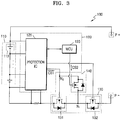
- FIG. 3 is a schematic block diagram of an internal structure of a battery pack according to an embodiment of the present disclosure.
- the battery management unit 120 may include a protection integrated circuit (IC) 121 and a micro-control unit (MCU, also referred to as a micro-controller) 123.
- the first switch 130 may include a charge switch 132 and a discharge switch 131.
- the protection IC 121 may monitor a voltage, a current, a temperature, a charge state, and/or the like of each of the battery cells 113.
- the protection IC 121 may transfer information about the monitored voltage, current, temperature, charge state, and/or the like of the battery cells 113 to the micro-control unit 123, and may operate the charge switch 132 and the discharge switch 131 under the control of the micro-control unit 123.
- the micro-control unit 123 is an integrated circuit (IC) electrically connected to the protection IC 121, and may analyze a state of the battery 110 based on the voltage, current, temperature, charge state, and/or the like of the battery cell 113 received via the protection IC 121.
- the micro-control unit 123 turns on/off the charge switch 132 and the discharge switch 131 by outputting a control signal corresponding to the state of the battery 110 to the protection IC 121.
- the micro-control unit 123 may generate a PWM signal.
- the micro-control unit 123 may output the PWM signal as the second control signal CS2 to be applied to the second switch 140.
- the second switch 140 may repeatedly (e.g., cyclically) turn-on/off in response to the applied PWM signal.
- the micro-control unit 123 may adjust a turn-on ratio of the second switch 140 by controlling a duty cycle of the PWM signal.
- the charge switch 132 and the discharge switch 131 may include a MOSFET.
- a drain and a source of the charge switch 132 may be arranged on a high current path of the battery 110. It is assumed that one of a drain and a source of the discharge switch 131 is a first electrode and the other is a second electrode. The first electrode and the second electrode of the discharge switch 131 are arranged on the high current path of the battery 110.
- a gate of the discharge switch 131 (hereinafter, referred to as a first control electrode) is electrically connected to the protection IC 121, and the first control signal is applied to the gate.
- a parasitic diode of the charge switch 132 is arranged such that a direction in which the discharge current of the battery 110 flows represents a forward bias direction of the parasitic diode.
- a parasitic diode of the discharge switch 131 is arranged such that a direction in which the charge current of the battery 110 flows represents a forward bias direction of the parasitic diode.
- the discharge switch 131 is turned off, the discharge current of the battery 110 is cut off.
- the discharge switch 131 is electrically connected to the negative terminal of the battery 110.
- the discharge switch 131 may include an N-type MOSFET.
- the second switch 140 is connected between the first control electrode and any one of the first electrode and the second electrode.
- a second control electrode that is a control electrode of the second switch 140 is electrically connected to the micro-control unit 123.
- any one of a drain and a source of the second switch 140 is a third electrode and the other is a fourth electrode, and that an electrode connected to any one electrode of the first electrode and the second electrode is the third electrode and an electrode electrically connected to the first control electrode is the fourth electrode
- each of the third electrode and fourth electrode corresponds to any one of a drain and a source of the second switch 140.
- the second switch 140 may include a P-type MOSFET rather than an N-type MOSFET. However, for convenience of explanation, the following description is based on an assumption that the second switch 140 includes an N-type MOSFET.
- the second switch 140 when the second switch 140 is turned on, the third electrode and the fourth electrode are electrically connected and thus the voltage of the second pack terminal P- is applied to the first control electrode.
- the voltage of the second pack terminal P- is a low level voltage and is applied to the first control electrode as a low level voltage.
- the second switch 140 short-circuits the first node N1 and the second node N2 as described above with reference to FIG. 2 , and thus a lower level signal is forcibly applied to the first control electrode.
- the first switch 130 is turned off, and thus a current flow between the first electrode and the second electrode is cut off.
- the micro-control unit 123 may control the discharge time of the battery 110 by adjusting the duty cycle of the PWM signal.
- the second switch 140 repeatedly turns-on and turns-off in response to the PWM signal of the second control signal CS2. Accordingly, when the second switch 140 is turned on, the voltage of the second pack terminal P- is applied to the first control electrode, and thus the discharge switch 131 is turned off. When the second switch 140 is turned off, a high level voltage in response to the first control signal CS1 is applied to the first control electrode, and thus the discharge switch 131 is turned on.
- the micro-control unit 123 controls the second switch 140 to forcibly turn off the discharge switch 131 according to the duty cycle.
- the micro-control unit 123 may adjust a turn-on rate of the discharge switch 131 by controlling the duty cycle.
- a proportion of the battery 110 being discharged per unit time may be controlled, and the amount of a discharge current per unit time may be adjusted by the duty cycle.
- the protection IC 121 applies a low level voltage signal as the first control signal to the discharge switch 131. In this case, even if the second switch 140 repeatedly turns-on and turns-off, the turned-off state of the discharge switch 131 is maintained.
- the micro-control unit 123 may output the second control signal CS2 having a first duty cycle to the discharge start point.
- the discharge start point is a point in time when an electrical connection of the capacitor 210 between the first pack terminal P+ and the second pack terminal P- is sensed or the capacitor 210 is electrically connected between the first pack terminal P+ and the second pack terminal P- in response to the start signal applied from the outside.
- a large inrush current may be generated.
- the micro-control unit 123 may reduce the amount of the inrush current by setting the first duty cycle to a large value to lower the turn-on rate per unit time of the discharge switch 131.
- the first duty cycle may be set based on the amount of an open discharge current of the protection devices included in the battery pack 100. For example, when a discharge current over 50 A flows, the protection devices are opened, and when the amount of the inrush current is about 200 A while the discharge switch 131 maintains a turned-on state, the first duty cycle is set to have a value over 80%. In this case, the battery pack 100 may limit the amount of the inrush current to be less than 50 A.
- the capacitor 210 After the discharge start point, the capacitor 210 is charged by receiving power from the battery 110, and the voltage between the opposite ends of the capacitor 210 increases. In this case, the amount of the inrush voltage that is a difference between the voltage between the opposite ends of the capacitor 210 and the voltage between the first pack terminal P+ and the second pack terminal P- decreases, and the amount of the discharge current of the battery 110 flowing into the capacitor 210 decreases as well. In this case, even when the micro-control unit 123 decreases the duty cycle of the second control signal CS2, a discharge current that is lower than or equal to a current value at which the protection device is opened (hereinafter, referred to as the allowable current) may be controlled to flow.
- the allowable current a discharge current that is lower than or equal to a current value at which the protection device is opened
- the micro-control unit 123 may output the second control signal CS2 having the first duty cycle at the discharge start point and then gradually decrease the duty cycle.
- the micro-control unit 123 outputs the second control signal CS2 having the first duty cycle to control the inrush current to be less than the allowable current, and then decreases the duty cycle of the second control signal CS2 to increase a charge time of the capacitor 210, thereby fully charging the capacitor 210 more rapidly.
- FIG. 4 is a schematic block diagram of an internal structure of a vacuum cleaner 10 according to an embodiment of the present disclosure.
- the vacuum cleaner 10 may include the battery pack 100, the capacitor 210, and a motor 221.
- the vacuum cleaner 10 may be driven by a user's input signal.
- the vacuum cleaner 10 may be driven by receiving a start signal through a switch or button located on an exterior surface.
- the capacitor 210 is electrically connected to the battery pack 100 and receives power from the battery pack 100 to start charging.
- the discharge switch 131 included in the battery pack 100 is arranged between the negative terminal of the battery 110 and the second pack terminal P- and includes an N-type MOSFET.
- the discharge switch 131 may include a P-type MOSFET rather than an N-type MOSFET, and those of ordinary skill in the art would know how to connect the circuit.
- the battery pack 100 When receiving a start signal, that is, at a discharge start point, the battery pack 100 starts discharging to charge the capacitor 210 connected between the first pack terminal P+ and the second pack terminal P-. As described above with reference to FIG. 1 , if no separate resistance element exists between the capacitor 210 and each of the first pack terminal P+ and the second pack terminal P-, a relatively large inrush current flows into the capacitor 210. When the amount of the inrush current is greater than the allowable current described with reference to FIG. 3 , the protection device, such as a fuse or a relay of the battery pack 100, is opened, and thus the vacuum cleaner 10 does not operate properly. Accordingly, the amount of the inrush current needs to be controlled to be lower than the allowable current.
- the battery pack 100 may limit the amount of the inrush current by outputting a PWM signal having the first duty cycle described with reference to FIG. 3 as the second control signal CS2. For example, when a discharge current over 50 A flows, the protection devices are opened. When the amount of the inrush current is about 200 A, the duty cycle of the second control signal CS2 is set to have a value over 80%. In this case, the battery pack 100 may limit the amount of the inrush current to be a value less than 50 A.
- the vacuum cleaner 10 is designed such that the time spent from the discharge start point to the operation of the motor is within the delay time described with reference to FIG. 3 .
- the vacuum cleaner 10 may operate the motor 221 within the delay time by reducing the time for charging the capacitor 210.
- the battery pack 100 may limit the amount of the inrush current flowing into the capacitor 210 by applying the second control signal CS2 having the first duty cycle to the second switch 140 at the discharge start point, and then decrease the duty cycle of the second control signal CS2.
- the battery pack 100 may increase the amount of the discharge current applied to the capacitor 210 per unit time by decreasing the duty cycle of the second control signal CS2.
- the battery pack 100 may gradually decrease the duty cycle as time passes to increase the time to charge the capacitor 210 with the discharge current of the battery 110, that is, an increase of a battery discharge time, thereby reducing the time to fully charge the capacitor 210.
- the battery pack 100 may limit the amount of the inrush current to be less than the allowable current by the second control signal CS2 having the first duty cycle at the discharge start point, and then gradually decrease the duty cycle of the second control signal CS2 to rapidly and fully charge the capacitor 210.
- the discharge switch 131 may be opened or closed with a relatively less control current, as compared to a case of directly controlling the discharge switch 131 by the PWM signal. Furthermore, in consideration that the discharge switch 131 is opened by the voltage of the first pack terminal P-, when a situation in which the battery 110 may be damaged is sensed, it may be guaranteed that the discharge switch 131 is still opened by the first control signal.
- first, second, third, etc. may be used herein to describe various elements, components, regions, layers and/or sections, these elements, components, regions, layers and/or sections should not be limited by these terms. These terms are used to distinguish one element, component, region, layer or section from another element, component, region, layer or section. Thus, a first element, component, region, layer or section discussed below could be termed a second element, component, region, layer or section, without departing from the spirit and scope of the inventive concept.
- the battery pack and/or any other relevant devices or components, such as the micro-controller and the protection IC, according to embodiments of the present invention described herein may be implemented utilizing any suitable hardware, firmware (e.g. an application-specific integrated circuit), software, or a suitable combination of software, firmware, and hardware.
- the various components of the battery pack may be formed on one integrated circuit (IC) chip or on separate IC chips.
- the various components of the battery pack may be implemented on a flexible printed circuit film, a tape carrier package (TCP), a printed circuit board (PCB), or formed on a same substrate.
- the various components of the battery pack may be a process or thread, running on one or more processors, in one or more computing devices, executing computer program instructions and interacting with other system components for performing the various functionalities described herein.
- the computer program instructions are stored in a memory which may be implemented in a computing device using a standard memory device, such as, for example, a random access memory (RAM).
- the computer program instructions may also be stored in other non-transitory computer readable media such as, for example, a CD-ROM, flash drive, or the like.
Landscapes
- Engineering & Computer Science (AREA)
- Mechanical Engineering (AREA)
- Power Engineering (AREA)
- Chemical & Material Sciences (AREA)
- Chemical Kinetics & Catalysis (AREA)
- Electrochemistry (AREA)
- General Chemical & Material Sciences (AREA)
- Microelectronics & Electronic Packaging (AREA)
- Manufacturing & Machinery (AREA)
- Charge And Discharge Circuits For Batteries Or The Like (AREA)
- Battery Mounting, Suspending (AREA)
- Protection Of Static Devices (AREA)
Abstract
Description
- Aspects of the present invention relate to a battery pack and a vacuum cleaner including the same.
- As portable electronic devices, such as mobile phones, digital cameras, notebook computers, and the like, are widely used, batteries for supplying power to operate these portable electronic devices have been actively developed. A battery is provided in the form of a battery pack with a protection integrated circuit (IC) for controlling charge and discharge of a battery. Various studies about charge methods and apparatuses to efficiently charge a battery have been performed.
- A battery may include a charge switch and a discharge switch. When a battery needs protection due to overcharge or overdischarge of the battery, at least one of the charge switch and the discharge switch is turned off. When a battery does not need to be protected, the charge switch and the discharge switch are continuously turned on to charge or discharge the battery.
- When power is applied from a battery pack to a motor included in power tools or vacuum cleaners requiring a large amount of power, in order to stably drive the motor, a high capacity capacitor is generally provided at opposite ends of the battery pack. In this case, at a moment when the capacitor and the battery pack are electrically connected to operate the motor, a large inrush current flowing into the capacitor is generated in the battery pack, and thus a protection device of the battery pack may be damaged due to the flow of the inrush current.
- Additional aspects will be set forth in part in the description which follows and, in part, will be apparent from the description, or may be learned by practice of the presented embodiments.
- According to one or more embodiments, there is provided a battery pack including: a battery including at least one battery cell; a terminal portion electrically connected to the battery and including a first pack terminal connected to an external load and a second pack terminal; a first switch configured to switch a discharge current of the battery according to a first control signal; a second switch configured to open or close according to a second control signal, and to open the first switch that is turned on by the first control signal, by a voltage of the first pack terminal or the second pack terminal; and a battery manager configured to output the first control signal and the second control signal.
- In some embodiments, the battery manager is configured to output, as the second control signal, a pulse width modulation signal having a pulse width varying according to a duty cycle.
- In some embodiments, the battery manager is configured to limit an amount of a discharge current of the battery by outputting the second control signal having a preset first duty cycle at a discharge start point when discharge starts.
- In some embodiments, the discharge start point is a point in time when an electric connection of the external load is sensed between the first pack terminal and the second pack terminal, or when the external load is electrically connected between the first pack terminal and the second pack terminal according to a start signal applied from the outside.
- In some embodiments, the battery manager is configured to output the second control signal having the first duty cycle and to then reduce the duty cycle of the second control signal.
- In some embodiments, the battery manager includes: a protection integrated circuit (IC) configured to sense a voltage of the battery and to output the first control signal; and a micro-controller configured to output the second control signal.
- According to one or more embodiments, there is provided a vacuum cleaner including: a battery pack; a capacitor electrically connected to the battery pack; and a motor connected in parallel to the capacitor, wherein the battery pack includes: a battery including at least one battery cell; a first pack terminal and a second pack terminal electrically connected to the battery, and electrically connected to the capacitor and the motor; a first switch configured to switch a discharge current of the battery according to a first control signal; a second switch configured to open or close according to a second control signal, and to open the first switch that is turned on by the first control signal, by a voltage of the first pack terminal or the second pack terminal; and a battery manager configured to output the first control signal and the second control signal.
- In some embodiments, the battery manager is configured to output, as the second control signal, a pulse width modulation signal having a pulse width varying according to a duty cycle.
- In some embodiments, the battery manager is configured to reduce an amount of an inrush current that is a current initially flowing into the capacitor, by outputting the second control signal having a preset first duty cycle at a discharge start point when the battery starts discharging.
- In some embodiments, the battery manager is configured to output the second control signal having the first duty cycle and then to gradually reduce the duty cycle of the second control signal.
- At least some of the above features that accord with the invention, and other features according to the invention, are set out in the claims.
- These and/or other aspects will become apparent and more readily appreciated from the following description of the embodiments, taken in conjunction with the accompanying drawings in which:
-
FIG. 1 is a schematic block diagram of a connection structure of a battery pack and an external load, according to an embodiment of the present disclosure; -
FIG. 2 is a schematic block diagram of an internal structure of a battery pack according to an embodiment of the present disclosure; -
FIG. 3 is a schematic block diagram of an internal structure of a battery pack according to an embodiment of the present disclosure; and -
FIG. 4 is a schematic block diagram of an internal structure of a vacuum cleaner according to an embodiment of the present disclosure. - The present inventive concept is described in detail with reference to the accompanying drawings. However, the present inventive concept is not limited thereto and it will be understood that various changes in form and details may be made therein without departing from the scope of the following claims. That is, descriptions on particular structures or functions may be presented merely for explaining embodiments of the present inventive concept.
- Unless defined otherwise, all terms used herein including technical or scientific terms have the same meanings as those generally understood by those of ordinary skill in the art to which the present inventive concept may pertain. The terms as those defined in generally used dictionaries are construed to have meanings matching that in the context of related technology and, unless clearly defined otherwise, are not construed to be ideally or excessively formal.
-
FIG. 1 is a schematic block diagram of a connection structure of abattery pack 100 and anexternal load 200, according to an embodiment of the present disclosure. - Referring to
FIG. 1 , theexternal load 200 may include aload 220 and acapacitor 210 that are connected in parallel to thebattery pack 100 to provide stable power to theload 220. - The
battery pack 100 may receive and store power from an external system and supply the stored power to theload 220. Thebattery pack 100 may include a protection switch that is open when an overcurrent flows inside to prevent a battery cell or a protection device included in thebattery pack 100 from being damaged or from exploding due to the overcurrent. - The
load 220 may consume the power stored in thebattery pack 100 by receiving the power stored in abattery 110 and thecapacitor 210. Theload 220 may be an apparatus including a motor, such as an electric vacuum cleaner or a power tool. Theload 220 may rotate the motor by receiving the power stored in thebattery pack 100. - The
capacitor 210 is arranged between thebattery pack 100 and theload 220 to stably supply the power of thebattery pack 100 to theload 220. Thecapacitor 210 may stabilize a voltage of thebattery pack 100 so that the voltage of thebattery pack 100 may be applied to theload 220 as a constant value. For example, thecapacitor 210 may absorb noise generated from the motor. Furthermore, when connected to aninductor load 220 such as the motor, thecapacitor 210 may compensate for a power factor. - The battery pack 100, when electrically connected to the
capacitor 210, is discharged to charge thecapacitor 210. When the charge of thecapacitor 210 is completed, theload 220 starts, or is driven, to operate. A time spent until the operation of theload 220 starts after the charge of thecapacitor 210 starts is referred to as a start delay time. For example, the start delay time is a time after an application of a start signal in a vacuum cleaner or a power tool until a motor included in the vacuum cleaner or the power tool is driven. - If no separate resistance element exists between the
battery pack 100 and thecapacitor 210 when thebattery pack 100 is electrically connected to thecapacitor 210 in response to the start signal (hereinafter, referred to as a discharge start point), thebattery pack 100 discharges a relatively large current to charge thecapacitor 210. The current flowing in the capacitor at the discharge start point may be referred to as an inrush current. In detail, the amount of current discharged by thebattery pack 100 to charge thecapacitor 210 may be determined by a difference between the voltage of thebattery pack 100 and a voltage of thecapacitor 210, resistance of a wire between thecapacitor 210 and thebattery pack 100, and an internal resistance of thebattery pack 100. In other words, the amount of current to charge thecapacitor 210 is a value obtained by dividing a value obtained by subtracting the voltage of thecapacitor 210 from the voltage of thebattery pack 100 by a value obtained by summing the resistance of the wire and the internal resistance of thebattery pack 100. A voltage between opposite ends of thecapacitor 210 when thebattery pack 100 starts to charge thecapacitor 210 is around 0 V. For example, when the voltage of thebattery pack 100 is 37.8 V, the voltage before thecapacitor 210 is charged is 0 V, and the sum of the internal resistance and the wire resistance is 150 mΩ, the amount of a discharge current (or an inrush current) when the charge of thecapacitor 210 starts is 37.8/015 that is about 252 A. - The discharge start point is a point in time when the battery pack 100 and the
capacitor 210 are electrically connected to each other by receiving a start signal from the outside. In response to the start signal, a separate switching device included in thebattery pack 100 or a separate switching device included in theexternal load 200 is turned on, and thus thebattery pack 100 and thecapacitor 210 may be electrically connected to each other, or as afirst switch 130 of thebattery pack 100 is turned on, thebattery pack 100 and thecapacitor 210 may be electrically connected to each other. - As such, the amount of inrush current flowing into the
capacitor 210 as thebattery pack 100 is discharged at a point when the charge of thecapacitor 210 starts. If the amount of inrush current is not limited, a fuse or a relay that is a protection device of thebattery pack 100 may be abnormally opened, and thus power may not be normally supplied to theload 220. - In consideration of the above matters, the
battery pack 100 may form a separate path including a resistor and a switch to limit the inrush current that is an initial charge current of thecapacitor 210. In this case, thebattery pack 100 may include a resistor and a high performance FET switch. Even when thecapacitor 210 is charged and a difference between the voltage between the opposite ends of thecapacitor 210 and the voltage of the battery pack 100 (hereinafter, referred to as the inrush voltage) decreases, thecapacitor 210 is charged by a current value by the resistance device. In other words, as the charging of thecapacitor 210 progresses, an amount of a discharge current to charge thecapacitor 210 gradually decreases. In this viewpoint, forming a separate path may considerably delay a time to fully charge thecapacitor 210, and also a delay time that is a time spent from the discharge start point to the operation of theload 220 may prolong, which is inefficient. Accordingly, while the amount of the inrush current flowing into thecapacitor 210 is limited, a new method of reducing the delay time of theload 220 is needed and described below in further detail. -
FIG. 2 is a schematic block diagram of an internal structure of a battery pack according to an embodiment of the present disclosure. - Referring to
FIG. 2 , thebattery pack 100 may include thebattery 110, a battery management unit (e.g., battery manager) 120, a first pack terminal P+, a second pack terminal P-, thefirst switch 130, and asecond switch 140. - The
battery 110 is a component for storing power and may include at least onebattery cell 113. Thebattery 110 may include a plurality ofbattery cells 113, and thebattery cells 113 may be connected to one another serially, in parallel, or in a serial-parallel combination. The number and connection method of thebattery cells 113 included in thebattery 110 may be determined according to the desired output voltage and power storage capacity. - The
battery cell 113 may include a chargeable secondary battery. For example, thebattery cell 113 may include a nickel-cadmium battery, a lead storage battery, a nickel metal hydride battery (NiMH), a lithium ion battery, a lithium polymer battery, and the like, but the present disclosure is not limited thereto. - The
battery management unit 120 is connected to thebattery 110, and may control charge and discharge operations of thebattery 110. Thebattery management unit 120 may monitor the voltage, current, temperature, residual power, lifespan, charge status, and/or the like of thebattery 110. Thebattery management unit 120 may detect a situation in which thebattery 110 exceeds a preset voltage or a preset current amount so that thebattery 110 is likely to be damaged, and opens thefirst switch 130 to protect thebattery 110. In other words, thebattery management unit 120 may perform an overcharge protection function, an over-discharge protection function, an overcurrent protection function, an overvoltage protection function, an overheat protection function, and/or the like of thebattery 110. - The first pack terminal P+ may be electrically connected to the positive terminal (i.e., cathode) of the battery, and the second pack terminal P- may be electrically connected to the negative terminal (i.e., anode) of the
battery 110. The first pack terminal P+ and the second pack terminal P- may be electrically connected to an external apparatus to supply the power of thebattery pack 100 externally to theload 220 or to receive power from the outside. For example, the first pack terminal P+ and the second pack terminal P- may be formed in wiring patterns, such as electrodes, connectors, lands, or pads, for the electric connection to the external apparatus. - The
first switch 130 is arranged between thebattery 110 and the second pack terminal P-. Thefirst switch 130 may receive a first control signal CS1 from thebattery management unit 120 to switch current to charge and discharge thebattery 110. Thefirst switch 130 may include a relay or a FET switch. - For convenience of explanation, it is assumed that the
first switch 130 is turned off when a low level voltage is applied as a control signal and turned on when a high level voltage is applied as a control signal. - The
second switch 140 is electrically connected between a second node N2 that is a node where thebattery management unit 120 and thefirst switch 130 are electrically connected and a first node N1 that is a node between the second pack terminal P- and thefirst switch 130 or between thebattery 110 and thefirst switch 130. Thesecond switch 140 may forcibly turn off thefirst switch 130 by applying a voltage of the first node N1 (i.e., a voltage of the second pack terminal) to the second node N2. For example, when thefirst switch 130 is turned off as the first control signal CS1 is shifted from a high level voltage signal to a low level voltage signal, and thesecond switch 140 is turned on as the second pack terminal P- connected to a negative terminal of thebattery 110 has a low level voltage, a voltage corresponding to the low level voltage signal applied to the second pack terminal P- is supplied as the second node N2. In this case, even when thebattery management unit 120 outputs the first control signal CS1 having a high level voltage, thefirst switch 130 is turned off as a low level signal is forcibly applied as a control signal due to the turn-on of thesecond switch 140. In other words, thesecond switch 140 may forcibly turn off thefirst switch 130 by the voltage of the first node N1. - According to an embodiment, the
battery management unit 120 may open or close thefirst switch 130 by applying a second control signal CS2, independent of the first control signal CS1, to thesecond switch 140. The second control signal CS2 may be a pulse width modulation (PWM) signal having a pulse width that is modulated according to a duty cycle. Thesecond switch 140 cyclically repeats turning on/off according to the pulse width modulation signal. When thesecond switch 140 is turned on, a low level voltage is applied as a control signal of thefirst switch 130 and thus thefirst switch 130 is forcibly turned off. Thefirst switch 130 is turned on only when thesecond switch 140 is turned off and thus a discharge current of thebattery 110 may flow to the second pack terminal P-. In this method, the amount of the discharge current of thebattery 110 may be controlled. - According to an embodiment, while the
battery management unit 120 continuously outputs the first control signal CS1 to turn on thefirst switch 130 to thefirst switch 130, it may turn off thefirst switch 130 by outputting the second control signal CS2 to turn on thesecond switch 140. For example, when a situation to protect thebattery 110 occurs during the adjustment of the amount of the discharge current of thebattery 110, thebattery management unit 120 may turn off thefirst switch 130 by outputting the first control signal CS1 of a low level voltage to thefirst switch 130, independently of outputting the second control signal CS2. For example, when thebattery 110 is exposed to a high temperature so that discharge needs to be stopped, thebattery management unit 120 outputting the second control signal CS2 may output a low level voltage signal as the first control signal CS1, thereby opening thefirst switch 130. In this case, the first control signal CS1 has a low level voltage and, even when thesecond switch 140 is turned off in response to the second control signal CS2, thefirst switch 130 maintains a turned-off state as the low level voltage of the first control signal CS1 is continuously applied thereto. In other words, thebattery management unit 120 may control thesecond switch 140, thereby protecting thebattery 110 in response to the first control signal CS1 and controlling the amount of the discharge current of thebattery 110. -
FIG. 3 is a schematic block diagram of an internal structure of a battery pack according to an embodiment of the present disclosure. - Referring to
FIG. 3 , thebattery management unit 120 may include a protection integrated circuit (IC) 121 and a micro-control unit (MCU, also referred to as a micro-controller) 123. Thefirst switch 130 may include acharge switch 132 and adischarge switch 131. - In the following description, when a low level voltage signal is applied as a control signal to the
discharge switch 131 of thefirst switch 130, thedischarge switch 131 is turned off, and the second pack terminal P- is electrically connected to the negative terminal of thebattery 110. - The
protection IC 121 may monitor a voltage, a current, a temperature, a charge state, and/or the like of each of thebattery cells 113. Theprotection IC 121 may transfer information about the monitored voltage, current, temperature, charge state, and/or the like of thebattery cells 113 to themicro-control unit 123, and may operate thecharge switch 132 and thedischarge switch 131 under the control of themicro-control unit 123. - The
micro-control unit 123 is an integrated circuit (IC) electrically connected to theprotection IC 121, and may analyze a state of thebattery 110 based on the voltage, current, temperature, charge state, and/or the like of thebattery cell 113 received via theprotection IC 121. Themicro-control unit 123 turns on/off thecharge switch 132 and thedischarge switch 131 by outputting a control signal corresponding to the state of thebattery 110 to theprotection IC 121. - The
micro-control unit 123 may generate a PWM signal. Themicro-control unit 123 may output the PWM signal as the second control signal CS2 to be applied to thesecond switch 140. Thesecond switch 140 may repeatedly (e.g., cyclically) turn-on/off in response to the applied PWM signal. Themicro-control unit 123 may adjust a turn-on ratio of thesecond switch 140 by controlling a duty cycle of the PWM signal. - The
charge switch 132 and thedischarge switch 131 may include a MOSFET. A drain and a source of thecharge switch 132 may be arranged on a high current path of thebattery 110. It is assumed that one of a drain and a source of thedischarge switch 131 is a first electrode and the other is a second electrode. The first electrode and the second electrode of thedischarge switch 131 are arranged on the high current path of thebattery 110. A gate of the discharge switch 131 (hereinafter, referred to as a first control electrode) is electrically connected to theprotection IC 121, and the first control signal is applied to the gate. - A parasitic diode of the
charge switch 132 is arranged such that a direction in which the discharge current of thebattery 110 flows represents a forward bias direction of the parasitic diode. When thecharge switch 132 is turned off, a charge current of thebattery 110 is cut off. A parasitic diode of thedischarge switch 131 is arranged such that a direction in which the charge current of thebattery 110 flows represents a forward bias direction of the parasitic diode. When thedischarge switch 131 is turned off, the discharge current of thebattery 110 is cut off. Thedischarge switch 131 is electrically connected to the negative terminal of thebattery 110. In this case, thedischarge switch 131 may include an N-type MOSFET. - The
second switch 140 is connected between the first control electrode and any one of the first electrode and the second electrode. A second control electrode that is a control electrode of thesecond switch 140 is electrically connected to themicro-control unit 123. Assuming that any one of a drain and a source of thesecond switch 140 is a third electrode and the other is a fourth electrode, and that an electrode connected to any one electrode of the first electrode and the second electrode is the third electrode and an electrode electrically connected to the first control electrode is the fourth electrode, each of the third electrode and fourth electrode corresponds to any one of a drain and a source of thesecond switch 140. Thesecond switch 140 inFIG. 2 is an N-type MOSFET and may be turned off when the second control signal CS2 is a low level and turned on when the second control signal CS2 is a high level. In some examples, thesecond switch 140 may include a P-type MOSFET rather than an N-type MOSFET. However, for convenience of explanation, the following description is based on an assumption that thesecond switch 140 includes an N-type MOSFET. - According to an embodiment, when the
second switch 140 is turned on, the third electrode and the fourth electrode are electrically connected and thus the voltage of the second pack terminal P- is applied to the first control electrode. In this case, the voltage of the second pack terminal P- is a low level voltage and is applied to the first control electrode as a low level voltage. Even when the first control signal of a high level voltage signal is applied to thefirst switch 130, thesecond switch 140 short-circuits the first node N1 and the second node N2 as described above with reference toFIG. 2 , and thus a lower level signal is forcibly applied to the first control electrode. In this case, thefirst switch 130 is turned off, and thus a current flow between the first electrode and the second electrode is cut off. - According to an embodiment, the
micro-control unit 123 may control the discharge time of thebattery 110 by adjusting the duty cycle of the PWM signal. For example, thesecond switch 140 repeatedly turns-on and turns-off in response to the PWM signal of the second control signal CS2. Accordingly, when thesecond switch 140 is turned on, the voltage of the second pack terminal P- is applied to the first control electrode, and thus thedischarge switch 131 is turned off. When thesecond switch 140 is turned off, a high level voltage in response to the first control signal CS1 is applied to the first control electrode, and thus thedischarge switch 131 is turned on. In the above method, themicro-control unit 123 controls thesecond switch 140 to forcibly turn off thedischarge switch 131 according to the duty cycle. In other words, themicro-control unit 123 may adjust a turn-on rate of thedischarge switch 131 by controlling the duty cycle. In this case, a proportion of thebattery 110 being discharged per unit time may be controlled, and the amount of a discharge current per unit time may be adjusted by the duty cycle. When thebattery 110 is exposed to a dangerous situation, theprotection IC 121 applies a low level voltage signal as the first control signal to thedischarge switch 131. In this case, even if thesecond switch 140 repeatedly turns-on and turns-off, the turned-off state of thedischarge switch 131 is maintained. - According to an embodiment, the
micro-control unit 123 may output the second control signal CS2 having a first duty cycle to the discharge start point. The discharge start point is a point in time when an electrical connection of thecapacitor 210 between the first pack terminal P+ and the second pack terminal P- is sensed or thecapacitor 210 is electrically connected between the first pack terminal P+ and the second pack terminal P- in response to the start signal applied from the outside. When no separate resistant element exists between thecapacitor 210 and the first pack terminal P+ and the second pack terminal P- at the discharge start point, a large inrush current may be generated. Themicro-control unit 123 may reduce the amount of the inrush current by setting the first duty cycle to a large value to lower the turn-on rate per unit time of thedischarge switch 131. The first duty cycle may be set based on the amount of an open discharge current of the protection devices included in thebattery pack 100. For example, when a discharge current over 50 A flows, the protection devices are opened, and when the amount of the inrush current is about 200 A while thedischarge switch 131 maintains a turned-on state, the first duty cycle is set to have a value over 80%. In this case, thebattery pack 100 may limit the amount of the inrush current to be less than 50 A. - After the discharge start point, the
capacitor 210 is charged by receiving power from thebattery 110, and the voltage between the opposite ends of thecapacitor 210 increases. In this case, the amount of the inrush voltage that is a difference between the voltage between the opposite ends of thecapacitor 210 and the voltage between the first pack terminal P+ and the second pack terminal P- decreases, and the amount of the discharge current of thebattery 110 flowing into thecapacitor 210 decreases as well. In this case, even when themicro-control unit 123 decreases the duty cycle of the second control signal CS2, a discharge current that is lower than or equal to a current value at which the protection device is opened (hereinafter, referred to as the allowable current) may be controlled to flow. - According to an embodiment, the
micro-control unit 123 may output the second control signal CS2 having the first duty cycle at the discharge start point and then gradually decrease the duty cycle. In this case, furthermore, when the duty cycle of the second control signal CS2 decreases, the turn-on rate of thefirst switch 130 increases, and thus thecapacitor 210 may be fully charged at a relatively faster speed. In other words, themicro-control unit 123 outputs the second control signal CS2 having the first duty cycle to control the inrush current to be less than the allowable current, and then decreases the duty cycle of the second control signal CS2 to increase a charge time of thecapacitor 210, thereby fully charging thecapacitor 210 more rapidly. -
FIG. 4 is a schematic block diagram of an internal structure of a vacuum cleaner 10 according to an embodiment of the present disclosure. - Referring to
FIG. 4 , the vacuum cleaner 10 may include thebattery pack 100, thecapacitor 210, and amotor 221. The vacuum cleaner 10 may be driven by a user's input signal. For example, the vacuum cleaner 10 may be driven by receiving a start signal through a switch or button located on an exterior surface. When the start signal is received, thecapacitor 210 is electrically connected to thebattery pack 100 and receives power from thebattery pack 100 to start charging. - In the following description, it is assumed that the
discharge switch 131 included in thebattery pack 100 is arranged between the negative terminal of thebattery 110 and the second pack terminal P- and includes an N-type MOSFET. However, in some example, thedischarge switch 131 may include a P-type MOSFET rather than an N-type MOSFET, and those of ordinary skill in the art would know how to connect the circuit. - When receiving a start signal, that is, at a discharge start point, the
battery pack 100 starts discharging to charge thecapacitor 210 connected between the first pack terminal P+ and the second pack terminal P-. As described above with reference toFIG. 1 , if no separate resistance element exists between thecapacitor 210 and each of the first pack terminal P+ and the second pack terminal P-, a relatively large inrush current flows into thecapacitor 210. When the amount of the inrush current is greater than the allowable current described with reference toFIG. 3 , the protection device, such as a fuse or a relay of thebattery pack 100, is opened, and thus the vacuum cleaner 10 does not operate properly. Accordingly, the amount of the inrush current needs to be controlled to be lower than the allowable current. - According to an embodiment, the
battery pack 100 may limit the amount of the inrush current by outputting a PWM signal having the first duty cycle described with reference toFIG. 3 as the second control signal CS2. For example, when a discharge current over 50 A flows, the protection devices are opened. When the amount of the inrush current is about 200 A, the duty cycle of the second control signal CS2 is set to have a value over 80%. In this case, thebattery pack 100 may limit the amount of the inrush current to be a value less than 50 A. - The vacuum cleaner 10 is designed such that the time spent from the discharge start point to the operation of the motor is within the delay time described with reference to
FIG. 3 . In general, the vacuum cleaner 10 may operate themotor 221 within the delay time by reducing the time for charging thecapacitor 210. - According to an embodiment, the
battery pack 100 may limit the amount of the inrush current flowing into thecapacitor 210 by applying the second control signal CS2 having the first duty cycle to thesecond switch 140 at the discharge start point, and then decrease the duty cycle of the second control signal CS2. For example, thebattery pack 100 may increase the amount of the discharge current applied to thecapacitor 210 per unit time by decreasing the duty cycle of the second control signal CS2. For example, thebattery pack 100 may gradually decrease the duty cycle as time passes to increase the time to charge thecapacitor 210 with the discharge current of thebattery 110, that is, an increase of a battery discharge time, thereby reducing the time to fully charge thecapacitor 210. In other words, thebattery pack 100 may limit the amount of the inrush current to be less than the allowable current by the second control signal CS2 having the first duty cycle at the discharge start point, and then gradually decrease the duty cycle of the second control signal CS2 to rapidly and fully charge thecapacitor 210. - Accordingly, in reducing the inrush current, as the
battery pack 100 indirectly controls thedischarge switch 131 by a pack terminal voltage by applying a PWM signal to thesecond switch 140 of a low capacity, thedischarge switch 131 may be opened or closed with a relatively less control current, as compared to a case of directly controlling thedischarge switch 131 by the PWM signal. Furthermore, in consideration that thedischarge switch 131 is opened by the voltage of the first pack terminal P-, when a situation in which thebattery 110 may be damaged is sensed, it may be guaranteed that thedischarge switch 131 is still opened by the first control signal. - It should be understood that embodiments described herein should be considered in a descriptive sense only and not for purposes of limitation. Descriptions of features or aspects within each embodiment should typically be considered as available for other similar features or aspects in other embodiments.
- It will be understood that, although the terms "first", "second", "third", etc., may be used herein to describe various elements, components, regions, layers and/or sections, these elements, components, regions, layers and/or sections should not be limited by these terms. These terms are used to distinguish one element, component, region, layer or section from another element, component, region, layer or section. Thus, a first element, component, region, layer or section discussed below could be termed a second element, component, region, layer or section, without departing from the spirit and scope of the inventive concept.
- In addition, it will also be understood that when a component is referred to as being "between" two components, it can be the only component between the two components, or one or more intervening components may also be present.
- The terminology used herein is for the purpose of describing particular embodiments and is not intended to be limiting of the inventive concept. As used herein, the singular forms "a" and "an" are intended to include the plural forms as well, unless the context clearly indicates otherwise. It will be further understood that the terms "include," "including," "comprises," and/or "comprising," when used in this specification, specify the presence of stated features, integers, steps, operations, elements, and/or components, but do not preclude the presence or addition of one or more other features, integers, steps, operations, elements, components, and/or groups thereof. As used herein, the term "and/or" includes any and all combinations of one or more of the associated listed items. Expressions such as "at least one of," when preceding a list of elements, modify the entire list of elements and do not modify the individual elements of the list. Further, the use of "may" when describing embodiments of the inventive concept refers to "one or more embodiments of the inventive concept." Also, the term "exemplary" is intended to refer to an example or illustration.
- It will be understood that when an element or layer is referred to as being "on", "connected to", "coupled to", or "adjacent" another element or layer, it can be directly on, connected to, coupled to, or adjacent the other element or layer, or one or more intervening elements or layers may be present. When an element or layer is referred to as being "directly on," "directly connected to", "directly coupled to", or "immediately adjacent" another element or layer, there are no intervening elements or layers present.
- As used herein, the term "substantially," "about," and similar terms are used as terms of approximation and not as terms of degree, and are intended to account for the inherent variations in measured or calculated values that would be recognized by those of ordinary skill in the art.
- As used herein, the terms "use," "using," and "used" may be considered synonymous with the terms "utilize," "utilizing," and "utilized," respectively.
- The battery pack and/or any other relevant devices or components, such as the micro-controller and the protection IC, according to embodiments of the present invention described herein may be implemented utilizing any suitable hardware, firmware (e.g. an application-specific integrated circuit), software, or a suitable combination of software, firmware, and hardware. For example, the various components of the battery pack may be formed on one integrated circuit (IC) chip or on separate IC chips. Further, the various components of the battery pack may be implemented on a flexible printed circuit film, a tape carrier package (TCP), a printed circuit board (PCB), or formed on a same substrate. Further, the various components of the battery pack may be a process or thread, running on one or more processors, in one or more computing devices, executing computer program instructions and interacting with other system components for performing the various functionalities described herein. The computer program instructions are stored in a memory which may be implemented in a computing device using a standard memory device, such as, for example, a random access memory (RAM). The computer program instructions may also be stored in other non-transitory computer readable media such as, for example, a CD-ROM, flash drive, or the like. Also, a person of skill in the art should recognize that the functionality of various computing devices may be combined or integrated into a single computing device, or the functionality of a particular computing device may be distributed across one or more other computing devices without departing from the scope of the exemplary embodiments of the present invention.
- While one or more embodiments have been described with reference to the figures, it will be understood by those of ordinary skill in the art that various changes in form and details may be made therein without departing from the scope as defined by the following claims.
Claims (9)
- A battery pack comprising:a battery comprising at least one battery cell;a first pack terminal and a second pack terminal, each of the first pack terminal and the second pack terminal being electrically connected to a respective terminal of the battery and configured to be electrically connected to an external load;a first switch configured to switch a discharge current of the battery according to a first control signal;a second switch configured to open or close according to a second control signal, and to open the first switch that is turned on by the first control signal, by a voltage of the first pack terminal or the second pack terminal; anda battery manager configured to output the first control signal and the second control signal.
- A battery pack according to claim 1, wherein the battery manager is configured to output, as the second control signal, a pulse width modulation signal having a pulse width varying according to a duty cycle.
- A battery pack according to claim 2, wherein the battery manager is configured to limit an amount of a discharge current of the battery by outputting the second control signal having a preset first duty cycle at a discharge start point when discharge starts.
- A battery pack according to claim 3, wherein the discharge start point is a point in time when an electric connection of the external load is sensed between the first pack terminal and the second pack terminal, or when the external load is electrically connected between the first pack terminal and the second pack terminal according to a start signal applied from the outside.
- A battery pack according to claim 4, wherein the battery manager is configured to output the second control signal having the first duty cycle and to then reduce the duty cycle of the second control signal.
- A battery pack according to any preceding claim, wherein the battery manager comprises:a protection integrated circuit (IC) configured to sense a voltage of the battery and to output the first control signal; anda micro-controller configured to output the second control signal.
- A vacuum cleaner comprising:a battery pack as set out in any preceding claim;a capacitor electrically connected to the battery pack; anda motor connected in parallel to the capacitor;wherein the first pack terminal and the second pack terminal are electrically connected to the capacitor and the motor.
- A vacuum cleaner according to claim 7, wherein the battery manager is configured to reduce an amount of an inrush current that is a current initially flowing into the capacitor, by outputting the second control signal having a preset first duty cycle at a discharge start point when the battery starts discharging.
- A vacuum cleaner according to claim 8, wherein the battery manager is configured to output the second control signal having the first duty cycle and then to gradually reduce the duty cycle of the second control signal.
Applications Claiming Priority (1)
| Application Number | Priority Date | Filing Date | Title |
|---|---|---|---|
| KR1020160147632A KR102246769B1 (en) | 2016-11-07 | 2016-11-07 | The battery pack and a vacuum cleaner including the same |
Publications (2)
| Publication Number | Publication Date |
|---|---|
| EP3319201A1 true EP3319201A1 (en) | 2018-05-09 |
| EP3319201B1 EP3319201B1 (en) | 2020-09-30 |
Family
ID=60301794
Family Applications (1)
| Application Number | Title | Priority Date | Filing Date |
|---|---|---|---|
| EP17200441.8A Active EP3319201B1 (en) | 2016-11-07 | 2017-11-07 | Battery pack and vacuum cleaner including the same |
Country Status (3)
| Country | Link |
|---|---|
| US (1) | US10381847B2 (en) |
| EP (1) | EP3319201B1 (en) |
| KR (1) | KR102246769B1 (en) |
Families Citing this family (12)
| Publication number | Priority date | Publication date | Assignee | Title |
|---|---|---|---|---|
| US11857142B2 (en) | 2006-12-15 | 2024-01-02 | Omachron Intellectual Property Inc. | Surface cleaning apparatus having an energy storage member and a charger for an energy storage member |
| KR20170052095A (en) * | 2015-11-03 | 2017-05-12 | 현대자동차주식회사 | Battery control system and method for detecting fusion of relay |
| DE102018127502B4 (en) * | 2018-11-05 | 2022-04-07 | Metabowerke Gmbh | restart protection device |
| US10998595B2 (en) * | 2018-11-08 | 2021-05-04 | GM Global Technology Operations LLC | Modular vehicle battery |
| US11246465B2 (en) * | 2019-02-20 | 2022-02-15 | Omachron Intellectual Property Inc. | Surface cleaning apparatus having an energy storage member and a charger for an energy storage member |
| US11229333B2 (en) * | 2019-02-20 | 2022-01-25 | Omachron Intellectual Property Inc. | Surface cleaning apparatus having an energy storage member and a charger for an energy storage member |
| WO2020168415A1 (en) * | 2019-02-20 | 2020-08-27 | Omachron Intellectual Property Inc. | Surface cleaning apparatus having an energy storage member and a charger for an energy storage member |
| CN112564075B (en) * | 2020-12-21 | 2023-05-23 | 张成君 | Bidirectional charging line structure |
| CN112803548A (en) * | 2021-02-25 | 2021-05-14 | 沃太能源南通有限公司 | Charging and discharging device |
| US20240055883A1 (en) * | 2022-08-10 | 2024-02-15 | Coast Cutlery Co. | Converter for a rechargeable battery |
| WO2024196013A1 (en) * | 2023-03-22 | 2024-09-26 | 삼성전자 주식회사 | Home appliance comprising power converter employing overheating prevention method |
| WO2025005445A1 (en) * | 2023-06-28 | 2025-01-02 | 삼성전자 주식회사 | Cleaner for reducing inrush current and method for reducing inrush current of cleaner |
Citations (4)
| Publication number | Priority date | Publication date | Assignee | Title |
|---|---|---|---|---|
| WO2008009827A2 (en) * | 2006-07-21 | 2008-01-24 | Valeo Systemes De Controle Moteur | Supply circuit for a motor disposing of an element providing for power switching, a protection against polarity inversion and an element for limiting the inrush current of a capacitive element |
| US20110023264A1 (en) * | 2008-04-02 | 2011-02-03 | Miele & Cie. Kg | Electric device having an electric motor and storage battery pack |
| JP2011254650A (en) * | 2010-06-03 | 2011-12-15 | Shin Kobe Electric Mach Co Ltd | Electric power apparatus |
| US20130187468A1 (en) * | 2012-01-24 | 2013-07-25 | Google Inc. | Uninterruptible power supply control in distributed power architecture |
Family Cites Families (14)
| Publication number | Priority date | Publication date | Assignee | Title |
|---|---|---|---|---|
| US4835409A (en) * | 1988-02-26 | 1989-05-30 | Black & Decker Inc. | Corded/cordless dual-mode power-operated device |
| JPH08275383A (en) | 1995-03-28 | 1996-10-18 | Fukushima Nippon Denki Kk | Rush current preventive circuitry |
| US6850039B2 (en) * | 2003-05-02 | 2005-02-01 | O2Micro International Limited | Battery pack and a battery charging/discharging circuit incorporating the same |
| US7456614B2 (en) * | 2003-10-27 | 2008-11-25 | Sony Corporation | Battery pack |
| US7589499B2 (en) * | 2004-03-25 | 2009-09-15 | O2Micro International Limited | Over voltage transient controller |
| WO2007007655A1 (en) * | 2005-07-07 | 2007-01-18 | Kabushiki Kaisha Toshiba | Battery system |
| JP2010246225A (en) * | 2009-04-03 | 2010-10-28 | Sony Corp | Battery pack and charging method |
| US20110068735A1 (en) | 2009-09-22 | 2011-03-24 | Texas Instruments Incorporated | Systems and Methods of Accurate Control of Battery Pre-charge Current |
| JP5648451B2 (en) * | 2010-12-02 | 2015-01-07 | 日立工機株式会社 | Electric tool |
| JP5683372B2 (en) * | 2011-04-27 | 2015-03-11 | デクセリアルズ株式会社 | Charge / discharge control device, battery pack, electric device, and charge / discharge control method |
| US20160172933A1 (en) * | 2013-07-08 | 2016-06-16 | Thas Llc | Electric dc motor system |
| JP6558072B2 (en) * | 2015-05-21 | 2019-08-14 | ミツミ電機株式会社 | Battery protection integrated circuit, battery protection device, and battery pack |
| TWI618523B (en) * | 2015-07-29 | 2018-03-21 | Lg電子股份有限公司 | Vacuum cleaner |
| US10436845B2 (en) * | 2016-03-01 | 2019-10-08 | Faraday & Future Inc. | Electric vehicle battery monitoring system |
-
2016
- 2016-11-07 KR KR1020160147632A patent/KR102246769B1/en active Active
-
2017
- 2017-10-03 US US15/724,032 patent/US10381847B2/en active Active
- 2017-11-07 EP EP17200441.8A patent/EP3319201B1/en active Active
Patent Citations (4)
| Publication number | Priority date | Publication date | Assignee | Title |
|---|---|---|---|---|
| WO2008009827A2 (en) * | 2006-07-21 | 2008-01-24 | Valeo Systemes De Controle Moteur | Supply circuit for a motor disposing of an element providing for power switching, a protection against polarity inversion and an element for limiting the inrush current of a capacitive element |
| US20110023264A1 (en) * | 2008-04-02 | 2011-02-03 | Miele & Cie. Kg | Electric device having an electric motor and storage battery pack |
| JP2011254650A (en) * | 2010-06-03 | 2011-12-15 | Shin Kobe Electric Mach Co Ltd | Electric power apparatus |
| US20130187468A1 (en) * | 2012-01-24 | 2013-07-25 | Google Inc. | Uninterruptible power supply control in distributed power architecture |
Also Published As
| Publication number | Publication date |
|---|---|
| US10381847B2 (en) | 2019-08-13 |
| EP3319201B1 (en) | 2020-09-30 |
| US20180131205A1 (en) | 2018-05-10 |
| KR20180050960A (en) | 2018-05-16 |
| KR102246769B1 (en) | 2021-04-30 |
Similar Documents
| Publication | Publication Date | Title |
|---|---|---|
| EP3319201B1 (en) | Battery pack and vacuum cleaner including the same | |
| US8508190B2 (en) | Assembled battery system and assembled battery protection device | |
| US7990108B2 (en) | Charge detector | |
| KR101677679B1 (en) | Power management circuit for rechargeable battery stack | |
| US6329796B1 (en) | Power management circuit for battery systems | |
| CN101814725B (en) | Secondary battery | |
| US7605568B2 (en) | Deep under voltage recovery in a battery pack | |
| CN103580096B (en) | The system and method that direct battery unit for battery connects | |
| KR101975393B1 (en) | External battery | |
| KR100959612B1 (en) | Hybrid battery | |
| CN110137915B (en) | Battery protection circuit and battery pack having the same | |
| JP2023062164A (en) | battery management | |
| US20160226275A1 (en) | Overcharge protection apparatus for battery pack and overcharge protection system | |
| JP2008199717A (en) | Battery pack and charge control method | |
| CN106786852A (en) | A kind of charging circuit, battery bag and mobile terminal | |
| EP4586456A1 (en) | Battery management device and battery pack including the same | |
| US9385544B2 (en) | External battery | |
| EP4462634A1 (en) | Battery protection device and battery pack including the same | |
| US20250192593A1 (en) | Battery pack group and driving method thereof | |
| CN120728775A (en) | Battery charging and discharging system, battery and method |
Legal Events
| Date | Code | Title | Description |
|---|---|---|---|
| PUAI | Public reference made under article 153(3) epc to a published international application that has entered the european phase |
Free format text: ORIGINAL CODE: 0009012 |
|
| STAA | Information on the status of an ep patent application or granted ep patent |
Free format text: STATUS: REQUEST FOR EXAMINATION WAS MADE |
|
| 17P | Request for examination filed |
Effective date: 20171107 |
|
| AK | Designated contracting states |
Kind code of ref document: A1 Designated state(s): AL AT BE BG CH CY CZ DE DK EE ES FI FR GB GR HR HU IE IS IT LI LT LU LV MC MK MT NL NO PL PT RO RS SE SI SK SM TR |
|
| AX | Request for extension of the european patent |
Extension state: BA ME |
|
| GRAP | Despatch of communication of intention to grant a patent |
Free format text: ORIGINAL CODE: EPIDOSNIGR1 |
|
| STAA | Information on the status of an ep patent application or granted ep patent |
Free format text: STATUS: GRANT OF PATENT IS INTENDED |
|
| RIC1 | Information provided on ipc code assigned before grant |
Ipc: H02J 7/00 20060101AFI20200403BHEP Ipc: A47L 9/00 20060101ALI20200403BHEP |
|
| INTG | Intention to grant announced |
Effective date: 20200512 |
|
| GRAS | Grant fee paid |
Free format text: ORIGINAL CODE: EPIDOSNIGR3 |
|
| GRAA | (expected) grant |
Free format text: ORIGINAL CODE: 0009210 |
|
| STAA | Information on the status of an ep patent application or granted ep patent |
Free format text: STATUS: THE PATENT HAS BEEN GRANTED |
|
| AK | Designated contracting states |
Kind code of ref document: B1 Designated state(s): AL AT BE BG CH CY CZ DE DK EE ES FI FR GB GR HR HU IE IS IT LI LT LU LV MC MK MT NL NO PL PT RO RS SE SI SK SM TR |
|
| REG | Reference to a national code |
Ref country code: CH Ref legal event code: EP Ref country code: GB Ref legal event code: FG4D |
|
| REG | Reference to a national code |
Ref country code: AT Ref legal event code: REF Ref document number: 1319788 Country of ref document: AT Kind code of ref document: T Effective date: 20201015 |
|
| REG | Reference to a national code |
Ref country code: DE Ref legal event code: R096 Ref document number: 602017024517 Country of ref document: DE |
|
| REG | Reference to a national code |
Ref country code: IE Ref legal event code: FG4D |
|
| PG25 | Lapsed in a contracting state [announced via postgrant information from national office to epo] |
Ref country code: NO Free format text: LAPSE BECAUSE OF FAILURE TO SUBMIT A TRANSLATION OF THE DESCRIPTION OR TO PAY THE FEE WITHIN THE PRESCRIBED TIME-LIMIT Effective date: 20201230 Ref country code: BG Free format text: LAPSE BECAUSE OF FAILURE TO SUBMIT A TRANSLATION OF THE DESCRIPTION OR TO PAY THE FEE WITHIN THE PRESCRIBED TIME-LIMIT Effective date: 20201230 Ref country code: HR Free format text: LAPSE BECAUSE OF FAILURE TO SUBMIT A TRANSLATION OF THE DESCRIPTION OR TO PAY THE FEE WITHIN THE PRESCRIBED TIME-LIMIT Effective date: 20200930 Ref country code: SE Free format text: LAPSE BECAUSE OF FAILURE TO SUBMIT A TRANSLATION OF THE DESCRIPTION OR TO PAY THE FEE WITHIN THE PRESCRIBED TIME-LIMIT Effective date: 20200930 Ref country code: GR Free format text: LAPSE BECAUSE OF FAILURE TO SUBMIT A TRANSLATION OF THE DESCRIPTION OR TO PAY THE FEE WITHIN THE PRESCRIBED TIME-LIMIT Effective date: 20201231 Ref country code: FI Free format text: LAPSE BECAUSE OF FAILURE TO SUBMIT A TRANSLATION OF THE DESCRIPTION OR TO PAY THE FEE WITHIN THE PRESCRIBED TIME-LIMIT Effective date: 20200930 |
|
| REG | Reference to a national code |
Ref country code: AT Ref legal event code: MK05 Ref document number: 1319788 Country of ref document: AT Kind code of ref document: T Effective date: 20200930 |
|
| PG25 | Lapsed in a contracting state [announced via postgrant information from national office to epo] |
Ref country code: RS Free format text: LAPSE BECAUSE OF FAILURE TO SUBMIT A TRANSLATION OF THE DESCRIPTION OR TO PAY THE FEE WITHIN THE PRESCRIBED TIME-LIMIT Effective date: 20200930 Ref country code: LV Free format text: LAPSE BECAUSE OF FAILURE TO SUBMIT A TRANSLATION OF THE DESCRIPTION OR TO PAY THE FEE WITHIN THE PRESCRIBED TIME-LIMIT Effective date: 20200930 |
|
| REG | Reference to a national code |
Ref country code: NL Ref legal event code: MP Effective date: 20200930 |
|
| REG | Reference to a national code |
Ref country code: LT Ref legal event code: MG4D |
|
| PG25 | Lapsed in a contracting state [announced via postgrant information from national office to epo] |
Ref country code: RO Free format text: LAPSE BECAUSE OF FAILURE TO SUBMIT A TRANSLATION OF THE DESCRIPTION OR TO PAY THE FEE WITHIN THE PRESCRIBED TIME-LIMIT Effective date: 20200930 Ref country code: PT Free format text: LAPSE BECAUSE OF FAILURE TO SUBMIT A TRANSLATION OF THE DESCRIPTION OR TO PAY THE FEE WITHIN THE PRESCRIBED TIME-LIMIT Effective date: 20210201 Ref country code: CZ Free format text: LAPSE BECAUSE OF FAILURE TO SUBMIT A TRANSLATION OF THE DESCRIPTION OR TO PAY THE FEE WITHIN THE PRESCRIBED TIME-LIMIT Effective date: 20200930 Ref country code: LT Free format text: LAPSE BECAUSE OF FAILURE TO SUBMIT A TRANSLATION OF THE DESCRIPTION OR TO PAY THE FEE WITHIN THE PRESCRIBED TIME-LIMIT Effective date: 20200930 Ref country code: EE Free format text: LAPSE BECAUSE OF FAILURE TO SUBMIT A TRANSLATION OF THE DESCRIPTION OR TO PAY THE FEE WITHIN THE PRESCRIBED TIME-LIMIT Effective date: 20200930 Ref country code: SM Free format text: LAPSE BECAUSE OF FAILURE TO SUBMIT A TRANSLATION OF THE DESCRIPTION OR TO PAY THE FEE WITHIN THE PRESCRIBED TIME-LIMIT Effective date: 20200930 |
|
| PG25 | Lapsed in a contracting state [announced via postgrant information from national office to epo] |
Ref country code: IS Free format text: LAPSE BECAUSE OF FAILURE TO SUBMIT A TRANSLATION OF THE DESCRIPTION OR TO PAY THE FEE WITHIN THE PRESCRIBED TIME-LIMIT Effective date: 20210130 Ref country code: PL Free format text: LAPSE BECAUSE OF FAILURE TO SUBMIT A TRANSLATION OF THE DESCRIPTION OR TO PAY THE FEE WITHIN THE PRESCRIBED TIME-LIMIT Effective date: 20200930 Ref country code: ES Free format text: LAPSE BECAUSE OF FAILURE TO SUBMIT A TRANSLATION OF THE DESCRIPTION OR TO PAY THE FEE WITHIN THE PRESCRIBED TIME-LIMIT Effective date: 20200930 Ref country code: AT Free format text: LAPSE BECAUSE OF FAILURE TO SUBMIT A TRANSLATION OF THE DESCRIPTION OR TO PAY THE FEE WITHIN THE PRESCRIBED TIME-LIMIT Effective date: 20200930 Ref country code: AL Free format text: LAPSE BECAUSE OF FAILURE TO SUBMIT A TRANSLATION OF THE DESCRIPTION OR TO PAY THE FEE WITHIN THE PRESCRIBED TIME-LIMIT Effective date: 20200930 |
|
| PG25 | Lapsed in a contracting state [announced via postgrant information from national office to epo] |
Ref country code: MC Free format text: LAPSE BECAUSE OF FAILURE TO SUBMIT A TRANSLATION OF THE DESCRIPTION OR TO PAY THE FEE WITHIN THE PRESCRIBED TIME-LIMIT Effective date: 20200930 Ref country code: NL Free format text: LAPSE BECAUSE OF FAILURE TO SUBMIT A TRANSLATION OF THE DESCRIPTION OR TO PAY THE FEE WITHIN THE PRESCRIBED TIME-LIMIT Effective date: 20200930 Ref country code: SK Free format text: LAPSE BECAUSE OF FAILURE TO SUBMIT A TRANSLATION OF THE DESCRIPTION OR TO PAY THE FEE WITHIN THE PRESCRIBED TIME-LIMIT Effective date: 20200930 |
|
| REG | Reference to a national code |
Ref country code: CH Ref legal event code: PL |
|
| REG | Reference to a national code |
Ref country code: DE Ref legal event code: R097 Ref document number: 602017024517 Country of ref document: DE |
|
| PG25 | Lapsed in a contracting state [announced via postgrant information from national office to epo] |
Ref country code: LU Free format text: LAPSE BECAUSE OF NON-PAYMENT OF DUE FEES Effective date: 20201107 |
|
| PLBE | No opposition filed within time limit |
Free format text: ORIGINAL CODE: 0009261 |
|
| STAA | Information on the status of an ep patent application or granted ep patent |
Free format text: STATUS: NO OPPOSITION FILED WITHIN TIME LIMIT |
|
| REG | Reference to a national code |
Ref country code: BE Ref legal event code: MM Effective date: 20201130 |
|
| PG25 | Lapsed in a contracting state [announced via postgrant information from national office to epo] |
Ref country code: CH Free format text: LAPSE BECAUSE OF NON-PAYMENT OF DUE FEES Effective date: 20201130 Ref country code: LI Free format text: LAPSE BECAUSE OF NON-PAYMENT OF DUE FEES Effective date: 20201130 Ref country code: DK Free format text: LAPSE BECAUSE OF FAILURE TO SUBMIT A TRANSLATION OF THE DESCRIPTION OR TO PAY THE FEE WITHIN THE PRESCRIBED TIME-LIMIT Effective date: 20200930 |
|
| 26N | No opposition filed |
Effective date: 20210701 |
|
| PG25 | Lapsed in a contracting state [announced via postgrant information from national office to epo] |
Ref country code: IE Free format text: LAPSE BECAUSE OF NON-PAYMENT OF DUE FEES Effective date: 20201107 Ref country code: IT Free format text: LAPSE BECAUSE OF FAILURE TO SUBMIT A TRANSLATION OF THE DESCRIPTION OR TO PAY THE FEE WITHIN THE PRESCRIBED TIME-LIMIT Effective date: 20200930 |
|
| PG25 | Lapsed in a contracting state [announced via postgrant information from national office to epo] |
Ref country code: SI Free format text: LAPSE BECAUSE OF FAILURE TO SUBMIT A TRANSLATION OF THE DESCRIPTION OR TO PAY THE FEE WITHIN THE PRESCRIBED TIME-LIMIT Effective date: 20200930 |
|
| PG25 | Lapsed in a contracting state [announced via postgrant information from national office to epo] |
Ref country code: IS Free format text: LAPSE BECAUSE OF FAILURE TO SUBMIT A TRANSLATION OF THE DESCRIPTION OR TO PAY THE FEE WITHIN THE PRESCRIBED TIME-LIMIT Effective date: 20210130 Ref country code: TR Free format text: LAPSE BECAUSE OF FAILURE TO SUBMIT A TRANSLATION OF THE DESCRIPTION OR TO PAY THE FEE WITHIN THE PRESCRIBED TIME-LIMIT Effective date: 20200930 Ref country code: MT Free format text: LAPSE BECAUSE OF FAILURE TO SUBMIT A TRANSLATION OF THE DESCRIPTION OR TO PAY THE FEE WITHIN THE PRESCRIBED TIME-LIMIT Effective date: 20200930 Ref country code: CY Free format text: LAPSE BECAUSE OF FAILURE TO SUBMIT A TRANSLATION OF THE DESCRIPTION OR TO PAY THE FEE WITHIN THE PRESCRIBED TIME-LIMIT Effective date: 20200930 |
|
| PG25 | Lapsed in a contracting state [announced via postgrant information from national office to epo] |
Ref country code: MK Free format text: LAPSE BECAUSE OF FAILURE TO SUBMIT A TRANSLATION OF THE DESCRIPTION OR TO PAY THE FEE WITHIN THE PRESCRIBED TIME-LIMIT Effective date: 20200930 |
|
| PG25 | Lapsed in a contracting state [announced via postgrant information from national office to epo] |
Ref country code: BE Free format text: LAPSE BECAUSE OF NON-PAYMENT OF DUE FEES Effective date: 20201130 |
|
| P01 | Opt-out of the competence of the unified patent court (upc) registered |
Effective date: 20230528 |
|
| PGFP | Annual fee paid to national office [announced via postgrant information from national office to epo] |
Ref country code: DE Payment date: 20251104 Year of fee payment: 9 |
|
| PGFP | Annual fee paid to national office [announced via postgrant information from national office to epo] |
Ref country code: GB Payment date: 20251030 Year of fee payment: 9 |
|
| PGFP | Annual fee paid to national office [announced via postgrant information from national office to epo] |
Ref country code: FR Payment date: 20251117 Year of fee payment: 9 |