EP3319191A1 - Articulated guide for cables - Google Patents
Articulated guide for cables Download PDFInfo
- Publication number
- EP3319191A1 EP3319191A1 EP17198252.3A EP17198252A EP3319191A1 EP 3319191 A1 EP3319191 A1 EP 3319191A1 EP 17198252 A EP17198252 A EP 17198252A EP 3319191 A1 EP3319191 A1 EP 3319191A1
- Authority
- EP
- European Patent Office
- Prior art keywords
- clamp
- central partition
- clamps
- rotation
- cables
- Prior art date
- Legal status (The legal status is an assumption and is not a legal conclusion. Google has not performed a legal analysis and makes no representation as to the accuracy of the status listed.)
- Granted
Links
- 238000005192 partition Methods 0.000 claims description 66
- 238000005452 bending Methods 0.000 claims description 4
- 239000000463 material Substances 0.000 claims description 4
- 230000000295 complement effect Effects 0.000 claims description 3
- 239000004800 polyvinyl chloride Substances 0.000 description 2
- 229920000915 polyvinyl chloride Polymers 0.000 description 2
- 239000004020 conductor Substances 0.000 description 1
- 230000008878 coupling Effects 0.000 description 1
- 238000010168 coupling process Methods 0.000 description 1
- 238000005859 coupling reaction Methods 0.000 description 1
- 230000001419 dependent effect Effects 0.000 description 1
- 239000012777 electrically insulating material Substances 0.000 description 1
- 239000013307 optical fiber Substances 0.000 description 1
- 239000004417 polycarbonate Substances 0.000 description 1
- 229920000515 polycarbonate Polymers 0.000 description 1
Images


Classifications
-
- H—ELECTRICITY
- H02—GENERATION; CONVERSION OR DISTRIBUTION OF ELECTRIC POWER
- H02G—INSTALLATION OF ELECTRIC CABLES OR LINES, OR OF COMBINED OPTICAL AND ELECTRIC CABLES OR LINES
- H02G3/00—Installations of electric cables or lines or protective tubing therefor in or on buildings, equivalent structures or vehicles
- H02G3/02—Details
- H02G3/04—Protective tubing or conduits, e.g. cable ladders or cable troughs
- H02G3/0462—Tubings, i.e. having a closed section
- H02G3/0475—Tubings, i.e. having a closed section formed by a succession of articulated units
-
- F—MECHANICAL ENGINEERING; LIGHTING; HEATING; WEAPONS; BLASTING
- F16—ENGINEERING ELEMENTS AND UNITS; GENERAL MEASURES FOR PRODUCING AND MAINTAINING EFFECTIVE FUNCTIONING OF MACHINES OR INSTALLATIONS; THERMAL INSULATION IN GENERAL
- F16G—BELTS, CABLES, OR ROPES, PREDOMINANTLY USED FOR DRIVING PURPOSES; CHAINS; FITTINGS PREDOMINANTLY USED THEREFOR
- F16G13/00—Chains
- F16G13/12—Hauling- or hoisting-chains so called ornamental chains
- F16G13/16—Hauling- or hoisting-chains so called ornamental chains with arrangements for holding electric cables, hoses, or the like
Definitions
- the invention is comprised in the field of devices for laying conductor cables, such as electric cables or optical fiber cables, for example, particularly in offices or technical facilities for connecting different pieces of equipment to one another or to a power or data supply source.
- the invention relates to an articulated guide for cables formed by a plurality of clamps that are successively attached to one another in an articulated manner, each of these clamps comprising at least one arm demarcating a duct segment for cables, such that the succession of the duct segments of the clamps forms a duct for cables along the articulated guide, and in which the arm of each clamp has a free end and is elastically flexible, such that the bending of the arm laterally opens the duct segment for inserting a cable laterally therein.
- Document ES2330322T3 describes an articulated guide for cables of this type which has been developed and marketed by the applicant, in which the clamps are attached to one another by means of an articulation with a single transverse axis of rotation, perpendicular to the axial direction of the articulated guide for cables, and in which two contiguous clamps are coupled to one another by means of a lug formed at one end of the clamp which is laterally inserted into an oblong through hole formed at the corresponding opposite end of the contiguous clamp.
- this articulated guide for cables satisfactorily fulfills its purpose, it can be improved in terms of the ease of attaching two clamps to one another and of the freedom to devise bent paths with the articulated guide.
- the purpose of the invention is to provide an articulated guide for cables of the type indicated above, which allows more easily attaching the clamps to one another and provides a greater freedom to devise bent paths, all this without compromising robustness of the articulated guide and without significantly increasing its cost.
- each clamp is successively attached to one another by means of a ball-and-socket joint, such that each clamp can rotate in a relative manner with respect to the contiguous clamp to which it is attached about the ball-and-socket joint according to at least two axes of rotation perpendicular to one another and perpendicular to an axial direction of the articulated guide, each of the clamps comprising, respectively, at a first end and at a second end opposite one another according to the axial direction, a spherical ball male portion and a spherical socket female portion, configured such that the male portion of a clamp is inserted into the female portion of the contiguous clamp to form the spherical ball-and-socket joint, and in that the female portion of each clamp comprises an opening which is oriented in the axial direction and opens into the female portion, and in which this opening is elastically deformable by the pushing of the male portion
- the axial direction of the articulated guide is the longitudinal direction of the guide when the clamps are arranged forming a guide in a straight line, such as in Figures 1 and 14 .
- the opening is formed by two lips facing one another and extending from the female portion in the axial direction and having a cantilever free end, said lips progressively separating from one another in the direction away from the female portion and forming between them at their free end a seat to receive the male portion of the contiguous clamp before snap-fitting.
- This particular configuration of the opening makes it even easier to couple two clamps to one another since the coupling operation is performed by first placing the male portion of a clamp in the seat formed by the lips at the end of the other clamp, thereby obtaining a stable relative position, and then pushing one clamp against the other, whereby the male portion readily separates the lips extending from the female portion as it is inserted between said lips into said female portion.
- Each clamp preferably comprises a central partition and two of said arms extending on opposite sides of said central partition, said two arms demarcating with said central partition two duct segments separated by said central partition, the male portion and the female portion being formed in said central partition, at opposite ends thereof along the axial direction, wherein each clamp can rotate in a relative manner with respect to the contiguous clamp to which it is attached about the ball-and-socket joint according to at least a first axis of rotation perpendicular to the central partition and to the axial direction and a second axis of rotation perpendicular to the first axis of rotation and to the axial direction.
- the succession of the two duct segments thereby forms two ducts for cables along the articulated guide, separated by the succession of central partitions.
- the central partition of each clamp comprises first abutting means for limiting the rotation of the clamp according to the first axis of rotation perpendicular to the central partition, said first abutting means consisting of two lobes formed in the central partition on either side of the male portion and extending in the axial direction on the same plane as the central partition, and two abutting edges formed in the central partition on either side of the female portion and having a shape complementary to the shape of the lobes, such that when the clamp rotates a specific angle according to the first axis of rotation, one of the lobes of the central partition of the clamp abuts with one of the abutting edges of the central partition of the contiguous clamp to which it is attached.
- This configuration allows reliably limiting the angle of rotation of the clamps. An excessive angle of rotation which may cause an undesired interference between the arms of two contiguous clamps or an excessive curvature of the cables led through the articulated guide is thereby prevented.
- the central partition comprises two recessed areas formed in said central partition on either side of the female portion and on opposite sides of said central partition with respect to the central plane thereof, such that the lobe of the contiguous clamp slides on the corresponding recessed area when said clamp rotates according to the first axis of rotation, the abutting edges consisting of the step formed by each recessed area in the central partition, and in said recessed area the wall of the central partition has a curvature that moves the free end of this recessed area away from the central plane of the central partition, such that this curvature allows rotation of the clamp according to the second axis of rotation.
- This configuration offers the advantage that the central partition along the articulated guide, formed by the succession of the central partitions of the clamps, can be devoid of openings caused by rotation of the clamps, or in any case allows considerably reducing these openings.
- the central partition comprises two notches on either side of the female portion, such that the lobe of the contiguous clamp slides into said corresponding notch when said clamp rotates according to the first axis of rotation, the abutting edges consisting of the edge of said notch.
- the corresponding arms of the clamps are separated from one another by a gap, such that the duct for cables formed by the succession of the duct segments of the clamps is a discontinuous duct that is open at said gaps between the arms.
- the cables guided in the duct of the articulated guide are not protected from the surrounding environment. However, they have the advantage of narrower arms, and it is therefore easier to bend them for inserting the cables laterally into the duct. Furthermore, the articulated guide is more lightweight.
- the arm of a clamp in each pair of contiguous clamps attached to one another by the ball-and-socket joint, is fitted into the arm of the contiguous clamp to which it is attached, i.e., an end of one arm is inserted into an end of the other arm, such that the duct for cables formed by the succession of the duct segments of the clamps is a continuous duct that is closed by said arms, and in the area in which the two arms are fitted into one another, the external dimension of the inner arm is smaller than the internal dimension of the outer arm to allow relative rotation of one clamp with respect to another about the ball-and-socket joint.
- This configuration has the advantage that the cables guided in the duct of the articulated guide are protected from the surrounding environment, without this entailing an excessive limitation of the angle of rotation of the clamps.
- each of the clamps is a single part molded from polymeric material.
- Figures 1 to 13 show a first embodiment in which the clamps forming the articulated guide form two ducts for cables with side openings.
- the articulated guide 1 for cables is formed by a plurality of clamps 2 that are successively attached to one another in an articulated manner to form a duct for cables.
- the duct thus formed can be bent according to at least two axes of rotation perpendicular to one another as a result of the relative rotation of the clamps 2 with respect to one another, as will be seen below.
- the articulated guide 1 is constructed by attaching as many clamps 2 as necessary to one another to obtain a desired length of said articulated guide 1.
- Each clamp 2 comprises two arms 3, each of them demarcating a duct segment 4 for cables, such that the succession of these duct segments 4 of the clamps 2 attached to one another forms two ducts for cables along the articulated guide 1.
- the articulated guide 1 has been depicted in a straight position, i.e., in a position in which the duct segments 4 of the clamps 2 form a rectilinear duct.
- the axial direction X is the longitudinal direction of the articulated guide 1 in this straight position shown in Figure 1 .
- end units which are attached on one side to the contiguous clamp 2 in an articulated manner and on the other side to a corresponding support (not depicted) are arranged at the ends of the articulated guide 1.
- These end units are preferably provided with several holes 23 for the passage of cables in the axial direction X and with engagement means, such as for example pins 24, for fixing these end units of the articulated guide 1 to the corresponding support by pressure.
- these end units are each formed by an end part 19, 21 which is attached in an articulated manner to the contiguous clamp 2 and a cover part 20, 22 which is fixed to the end part 19, 21 by pressure.
- the clamps 2 are identical to one another. Their shape is depicted in detail in Figures 3 to 8 .
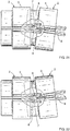
- Figures 9 to 13 show the attachment between two contiguous clamps 2, as well as the way in which these clamps 2 can rotate with respect to one another to bend the duct formed by the articulated guide 1.
- Each clamp 2 comprises a central partition 12 and two arms 3 extending respectively on two opposite sides thereof, such that each arm 3 demarcates a duct segment 4 with said central partition 12.
- the two arms 3 of each clamp 2 thereby form two duct segments 4 separated from one another by the central partition 12.
- Each arm 3 has a free end 5 and is elastically flexible, such that by bending the arm 3 the duct segment 4 can be opened laterally for inserting a cable laterally therein.
- the central partition 12 has a general disc shape and the two arms 3 are symmetrical with respect to the main plane thereof and have a general rib shape.
- the arms 3 have a semicircular path, projecting from a lateral end of the central partition 12 with their free end 5 ending a short distance from the latter.
- a spherical ball male portion 7 and a spherical socket female portion 8 are formed, respectively, at opposite ends of the central partition 12 along the axial direction X, which are also opposite ends of the clamp 2, where these portions are configured such that the male portion 7 of a clamp 2 is inserted into the female portion 8 of the contiguous clamp 2 to form a spherical ball-and-socket joint 6 constituting the articulated attachment of two contiguous clamps 2.
- Each clamp 2 can rotate about the ball-and-socket joint 6 in a relative manner with respect to the contiguous clamp 2 to which it is attached.
- This relative rotation of each clamp 2 is possible at least according to a first axis of rotation Y perpendicular to the central partition 12 and to the axial direction X, in two opposite directions of rotation as shown in Figures 12 and 13 , and a second axis of rotation Z perpendicular to said first axis of rotation Y and to said axial direction X, also in two opposite directions of rotation as shown in Figures 10 and 11 .
- Each clamp 2 comprises an opening 9 which is oriented in the axial direction X and opens into the female portion 8.
- This opening 9 is formed by two lips 10 facing one another and extending from the female portion 8 in the axial direction X and having a cantilever free end 11.
- the lips 10 progressively separate from one another in the direction away from the female portion 8, and form between them at their free end 11 a seat intended for receiving the male portion 7 of the contiguous clamp 2 before said snap-fitting.
- the male portion 7 When the two contiguous clamps 2 are pushed towards one another in the axial direction X, the male portion 7 is pushed towards the female portion 8 and forcefully makes its way between the lips 10, thereby causing the elastic bending of these lips which causes them to move away from one another and elastically deforms the opening 9 until the male portion 7 has passed through opening.
- the male portion 7 Once the male portion 7 has gone through the opening 9 by pressure and is housed in the female portion 8, as shown Figures 9 to 13 , the male portion 7 is snap-fitted into the female portion 8, thereby forming the ball-and-socket joint 6.
- the lips 10 must again be separated to pry the two portions 7 and 8 apart and this operation usually requires using a tool, such as a flat screwdriver, for example.
- first abutting means consisting, on one hand, of two symmetrical lobes 13 formed in the central partition 12 on either side of the male portion 7 and extending in the axial direction X substantially on the same plane as said central partition 12, and on the other hand, by two abutting edges 14A formed in said central partition 12 on either side of the female portion 8 and having a shape complementary to the shape of the lobes 13.
- the clamp 2 rotates a specific angle according to the first axis of rotation Y, one of the lobes 13 of the central partition 12 thereof abuts with one of the abutting edges 14A of the central partition 12 of the contiguous clamp 2.
- the two abutment positions in the two opposite directions of rotation are shown, respectively, in Figures 12 and 13 .
- the abutting edges 14A consist of the step formed by two symmetrical recessed areas 15 formed in the central partition 12 on either side of the female portion 8 and on opposite sides of said central partition 12 with respect to the central plane thereof.
- each clamp 2 When the clamp 2 rotates according to the first axis of rotation Y, the lobe 13 of the central partition 12 thereof slides on the corresponding recessed area 15 of the central partition 12 of the contiguous clamp, until the lobe 13 abuts against the edge 14A. Furthermore, in each recessed area 15 the wall of the central partition 12 has a curvature 16 that moves the free end of said recessed area 15 away from the central plane of said central partition 12. As a result of this curvature 16, each clamp 2 can rotate in a relative and limited manner with respect to the contiguous clamp 2 according to the second axis of rotation Z, as shown in Figures 10 and 11 .
- Each clamp 2 is a single part molded from polymeric material.
- Figures 14 to 24 show a second embodiment in which the clamps forming the articulated guide form two closed ducts for cables. This embodiment only differs from the first embodiment in the features described below.
- a first difference with respect to the first embodiment consists of the way in which the first abutting means limiting the relative rotation of the clamps 2 about the first axis of rotation Y are made.
- the central partition 12 of each clamp 2 comprises two notches 17 on either side of the female portion 8, such that the edges of these notches 17 constitute the abutting edges 14B.
- a second difference with respect to the first embodiment which is independent of the first difference described above, consists of the shape the arms 3 of the clamps 2 adopt so that the two ducts formed by the succession of said clamps are closed ducts.
- the arm 3 of a clamp 2 is fitted into the arm 3 of the contiguous clamp 2 to which it is attached, i.e., an end of one arm 3 is inserted into an end of the other arm 3.
- the two ducts for cables formed by the succession of the duct segments 4 of the clamps 2 are continuous ducts closed by the arms 3.
- the external dimension of the inner arm 3 is smaller than the internal dimension of the outer arm 3.
Abstract
Description
- The invention is comprised in the field of devices for laying conductor cables, such as electric cables or optical fiber cables, for example, particularly in offices or technical facilities for connecting different pieces of equipment to one another or to a power or data supply source.
- More specifically, the invention relates to an articulated guide for cables formed by a plurality of clamps that are successively attached to one another in an articulated manner, each of these clamps comprising at least one arm demarcating a duct segment for cables, such that the succession of the duct segments of the clamps forms a duct for cables along the articulated guide, and in which the arm of each clamp has a free end and is elastically flexible, such that the bending of the arm laterally opens the duct segment for inserting a cable laterally therein.
- Document
ES2330322T3 - The purpose of the invention is to provide an articulated guide for cables of the type indicated above, which allows more easily attaching the clamps to one another and provides a greater freedom to devise bent paths, all this without compromising robustness of the articulated guide and without significantly increasing its cost.
- This is achieved by means of an articulated guide for cables of the type indicated above, characterized in that the clamps are successively attached to one another by means of a ball-and-socket joint, such that each clamp can rotate in a relative manner with respect to the contiguous clamp to which it is attached about the ball-and-socket joint according to at least two axes of rotation perpendicular to one another and perpendicular to an axial direction of the articulated guide, each of the clamps comprising, respectively, at a first end and at a second end opposite one another according to the axial direction, a spherical ball male portion and a spherical socket female portion, configured such that the male portion of a clamp is inserted into the female portion of the contiguous clamp to form the spherical ball-and-socket joint, and in that the female portion of each clamp comprises an opening which is oriented in the axial direction and opens into the female portion, and in which this opening is elastically deformable by the pushing of the male portion towards the female portion in the axial direction for snap-fitting the male portion into the female portion.
- In the present document, the axial direction of the articulated guide is the longitudinal direction of the guide when the clamps are arranged forming a guide in a straight line, such as in
Figures 1 and14 . - As a result of this configuration according to the invention, two clamps are coupled to one another to form the articulated attachment with greater ease, i.e., by simply pushing one clamp against the other in the axial direction of the articulated guide. Furthermore, as a result of the articulated attachment being made by means of a spherical ball-and-socket joint, and of the male and female portions of this spherical ball-and-socket being arranged at the ends of the clamp in the axial direction, the limitation of the preceding design, in which each clamp can only rotate about a transverse axis, is overcome.
- Preferred embodiments the features of which are described in the dependent claims have been provided based on the invention defined in the main claim.
- In some preferred embodiments, the opening is formed by two lips facing one another and extending from the female portion in the axial direction and having a cantilever free end, said lips progressively separating from one another in the direction away from the female portion and forming between them at their free end a seat to receive the male portion of the contiguous clamp before snap-fitting. This particular configuration of the opening makes it even easier to couple two clamps to one another since the coupling operation is performed by first placing the male portion of a clamp in the seat formed by the lips at the end of the other clamp, thereby obtaining a stable relative position, and then pushing one clamp against the other, whereby the male portion readily separates the lips extending from the female portion as it is inserted between said lips into said female portion.
- Each clamp preferably comprises a central partition and two of said arms extending on opposite sides of said central partition, said two arms demarcating with said central partition two duct segments separated by said central partition, the male portion and the female portion being formed in said central partition, at opposite ends thereof along the axial direction, wherein each clamp can rotate in a relative manner with respect to the contiguous clamp to which it is attached about the ball-and-socket joint according to at least a first axis of rotation perpendicular to the central partition and to the axial direction and a second axis of rotation perpendicular to the first axis of rotation and to the axial direction. The succession of the two duct segments thereby forms two ducts for cables along the articulated guide, separated by the succession of central partitions. The possibility of the clamps rotating according to the two particular axes that have been mentioned allows running guided cables in these two separated ducts along bent paths that change planes in a particularly reliable manner since the succession of the central partitions of the clamps forms an articulated central partition that progressively follows the desired path that changes planes.
- In some preferred embodiments, the central partition of each clamp comprises first abutting means for limiting the rotation of the clamp according to the first axis of rotation perpendicular to the central partition, said first abutting means consisting of two lobes formed in the central partition on either side of the male portion and extending in the axial direction on the same plane as the central partition, and two abutting edges formed in the central partition on either side of the female portion and having a shape complementary to the shape of the lobes, such that when the clamp rotates a specific angle according to the first axis of rotation, one of the lobes of the central partition of the clamp abuts with one of the abutting edges of the central partition of the contiguous clamp to which it is attached. This configuration allows reliably limiting the angle of rotation of the clamps. An excessive angle of rotation which may cause an undesired interference between the arms of two contiguous clamps or an excessive curvature of the cables led through the articulated guide is thereby prevented.
- In some envisaged embodiments, the central partition comprises two recessed areas formed in said central partition on either side of the female portion and on opposite sides of said central partition with respect to the central plane thereof, such that the lobe of the contiguous clamp slides on the corresponding recessed area when said clamp rotates according to the first axis of rotation, the abutting edges consisting of the step formed by each recessed area in the central partition, and in said recessed area the wall of the central partition has a curvature that moves the free end of this recessed area away from the central plane of the central partition, such that this curvature allows rotation of the clamp according to the second axis of rotation. This configuration offers the advantage that the central partition along the articulated guide, formed by the succession of the central partitions of the clamps, can be devoid of openings caused by rotation of the clamps, or in any case allows considerably reducing these openings.
- In other envisaged embodiments, the central partition comprises two notches on either side of the female portion, such that the lobe of the contiguous clamp slides into said corresponding notch when said clamp rotates according to the first axis of rotation, the abutting edges consisting of the edge of said notch. This configuration does not have the aforementioned advantage, but it is simpler construction-wise and provides a particularly robust abutment of the angle of rotation.
- In some embodiments, in each pair of contiguous clamps attached to one another by the ball-and-socket joint, the corresponding arms of the clamps are separated from one another by a gap, such that the duct for cables formed by the succession of the duct segments of the clamps is a discontinuous duct that is open at said gaps between the arms. In these embodiments, the cables guided in the duct of the articulated guide are not protected from the surrounding environment. However, they have the advantage of narrower arms, and it is therefore easier to bend them for inserting the cables laterally into the duct. Furthermore, the articulated guide is more lightweight.
- In other embodiments, in each pair of contiguous clamps attached to one another by the ball-and-socket joint, the arm of a clamp is fitted into the arm of the contiguous clamp to which it is attached, i.e., an end of one arm is inserted into an end of the other arm, such that the duct for cables formed by the succession of the duct segments of the clamps is a continuous duct that is closed by said arms, and in the area in which the two arms are fitted into one another, the external dimension of the inner arm is smaller than the internal dimension of the outer arm to allow relative rotation of one clamp with respect to another about the ball-and-socket joint. This configuration has the advantage that the cables guided in the duct of the articulated guide are protected from the surrounding environment, without this entailing an excessive limitation of the angle of rotation of the clamps.
- In the preferred embodiments, each of the clamps is a single part molded from polymeric material.
- The invention also comprises other detailed features illustrated in the following detailed description of an embodiment of the invention and in the attached drawings.
- Other advantages and features of the invention can be seen from the following description in which preferred embodiments of the invention are described in reference to the attached drawings without limiting the scope of the main claim.
-
Figures 1 to 13 show a first embodiment of the articulated guide for cables according to the invention, in which the ducts for cables formed by the clamps are open ducts. -
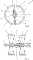
Figure 1 is a perspective view of the articulated guide in a straight position. -
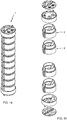
Figure 2 is an exploded perspective view of the articulated guide, in which only some of the clamps forming the articulated guide are shown. -
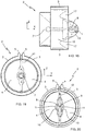
Figures 3 to 8 are a top perspective view, a bottom perspective view, a side view, a front view, a top view and a bottom view, respectively, of one of the clamps forming the articulated guide. -
Figure 9 is a front view of two contiguous clamps attached to one another forming the ball-and-socket joint, in a straight position. -
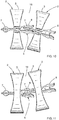
Figures 10 and 11 are front views of the two clamps in a tilted position, in which one clamp is rotated with respect to the other according to the second axis of rotation Z, in one direction and in the opposite direction, respectively. -
Figures 12 and 13 are side views of the two clamps in a tilted position, in which one clamp is rotated with respect to the other according to the first axis of rotation Y, in one direction and in the opposite direction, respectively. -
Figures 14 to 24 show a second embodiment of the articulated guide for cables according to the invention, in which the ducts for cables formed by the clamps are closed ducts. -
Figure 14 is a perspective view of the articulated guide in a straight position. -
Figure 15 is an exploded perspective view of the articulated guide, in which only some of the clamps forming the articulated guide are shown. -
Figures 16 to 20 are a top perspective view, a bottom perspective view, a side view, a top view and a bottom view, respectively, of one of the clamps forming the articulated guide. -
Figures 21 and 22 are front views of two contiguous clamps attached to one another forming the ball-and-socket joint, in a tilted position in which one clamp is rotated with respect to the other according to the second axis of rotation Z, in one direction and in the opposite direction, respectively. -
Figures 23 and 24 are side views of the two clamps in a tilted position in which one clamp is rotated with respect to the other according to the first axis of rotation Y, in one direction and in the opposite direction, respectively. -
Figures 1 to 13 show a first embodiment in which the clamps forming the articulated guide form two ducts for cables with side openings. - As can be seen
Figures 1 and 2 , the articulatedguide 1 for cables is formed by a plurality ofclamps 2 that are successively attached to one another in an articulated manner to form a duct for cables. The duct thus formed can be bent according to at least two axes of rotation perpendicular to one another as a result of the relative rotation of theclamps 2 with respect to one another, as will be seen below. The articulatedguide 1 is constructed by attaching asmany clamps 2 as necessary to one another to obtain a desired length of said articulatedguide 1. Eachclamp 2 comprises twoarms 3, each of them demarcating aduct segment 4 for cables, such that the succession of theseduct segments 4 of theclamps 2 attached to one another forms two ducts for cables along the articulatedguide 1. - In
Figure 1 , thearticulated guide 1 has been depicted in a straight position, i.e., in a position in which theduct segments 4 of theclamps 2 form a rectilinear duct. The axial direction X, to which reference will be made below, is the longitudinal direction of the articulatedguide 1 in this straight position shown inFigure 1 . - Preferably, end units which are attached on one side to the
contiguous clamp 2 in an articulated manner and on the other side to a corresponding support (not depicted) are arranged at the ends of the articulatedguide 1. These end units are preferably provided withseveral holes 23 for the passage of cables in the axial direction X and with engagement means, such as forexample pins 24, for fixing these end units of the articulatedguide 1 to the corresponding support by pressure. In the depicted embodiments, these end units are each formed by anend part contiguous clamp 2 and acover part end part - The
clamps 2 are identical to one another. Their shape is depicted in detail inFigures 3 to 8 .Figures 9 to 13 show the attachment between twocontiguous clamps 2, as well as the way in which theseclamps 2 can rotate with respect to one another to bend the duct formed by thearticulated guide 1. - Each
clamp 2 comprises acentral partition 12 and twoarms 3 extending respectively on two opposite sides thereof, such that eacharm 3 demarcates aduct segment 4 with saidcentral partition 12. The twoarms 3 of eachclamp 2 thereby form twoduct segments 4 separated from one another by thecentral partition 12. Eacharm 3 has afree end 5 and is elastically flexible, such that by bending thearm 3 theduct segment 4 can be opened laterally for inserting a cable laterally therein. In the depicted embodiment, thecentral partition 12 has a general disc shape and the twoarms 3 are symmetrical with respect to the main plane thereof and have a general rib shape. More specifically, thearms 3 have a semicircular path, projecting from a lateral end of thecentral partition 12 with theirfree end 5 ending a short distance from the latter. A spherical ballmale portion 7 and a spherical socketfemale portion 8 are formed, respectively, at opposite ends of thecentral partition 12 along the axial direction X, which are also opposite ends of theclamp 2, where these portions are configured such that themale portion 7 of aclamp 2 is inserted into thefemale portion 8 of thecontiguous clamp 2 to form a spherical ball-and-socket joint 6 constituting the articulated attachment of twocontiguous clamps 2. Eachclamp 2 can rotate about the ball-and-socket joint 6 in a relative manner with respect to thecontiguous clamp 2 to which it is attached. This relative rotation of eachclamp 2 is possible at least according to a first axis of rotation Y perpendicular to thecentral partition 12 and to the axial direction X, in two opposite directions of rotation as shown inFigures 12 and 13 , and a second axis of rotation Z perpendicular to said first axis of rotation Y and to said axial direction X, also in two opposite directions of rotation as shown inFigures 10 and 11 . - As can be seen
Figures 9 to 11 , in each pair ofcontiguous clamps 2 attached to one another by the ball-and-socket joint 6, the correspondingarms 3 of theclamps 2 are separated from one another by agap 18. The two ducts for cables thus formed by the succession of theduct segments 4 of theclamps 2 are therefore discontinuous ducts that are open laterally at thegaps 18 between thearms 3. - Each
clamp 2 comprises anopening 9 which is oriented in the axial direction X and opens into thefemale portion 8. Thisopening 9 is formed by twolips 10 facing one another and extending from thefemale portion 8 in the axial direction X and having a cantileverfree end 11. Thelips 10 progressively separate from one another in the direction away from thefemale portion 8, and form between them at their free end 11 a seat intended for receiving themale portion 7 of thecontiguous clamp 2 before said snap-fitting. When the twocontiguous clamps 2 are pushed towards one another in the axial direction X, themale portion 7 is pushed towards thefemale portion 8 and forcefully makes its way between thelips 10, thereby causing the elastic bending of these lips which causes them to move away from one another and elastically deforms theopening 9 until themale portion 7 has passed through opening. Once themale portion 7 has gone through theopening 9 by pressure and is housed in thefemale portion 8, as shownFigures 9 to 13 , themale portion 7 is snap-fitted into thefemale portion 8, thereby forming the ball-and-socket joint 6. Thelips 10 must again be separated to pry the twoportions - As can be seen
Figures 12 and 13 , the relative rotation of theclamps 2 about the first axis of rotation Y is limited by first abutting means consisting, on one hand, of twosymmetrical lobes 13 formed in thecentral partition 12 on either side of themale portion 7 and extending in the axial direction X substantially on the same plane as saidcentral partition 12, and on the other hand, by two abuttingedges 14A formed in saidcentral partition 12 on either side of thefemale portion 8 and having a shape complementary to the shape of thelobes 13. When theclamp 2 rotates a specific angle according to the first axis of rotation Y, one of thelobes 13 of thecentral partition 12 thereof abuts with one of the abuttingedges 14A of thecentral partition 12 of thecontiguous clamp 2. The two abutment positions in the two opposite directions of rotation are shown, respectively, inFigures 12 and 13 . In the embodiments shown in these drawings, the abuttingedges 14A consist of the step formed by two symmetrical recessedareas 15 formed in thecentral partition 12 on either side of thefemale portion 8 and on opposite sides of saidcentral partition 12 with respect to the central plane thereof. When theclamp 2 rotates according to the first axis of rotation Y, thelobe 13 of thecentral partition 12 thereof slides on the corresponding recessedarea 15 of thecentral partition 12 of the contiguous clamp, until thelobe 13 abuts against theedge 14A. Furthermore, in each recessedarea 15 the wall of thecentral partition 12 has acurvature 16 that moves the free end of said recessedarea 15 away from the central plane of saidcentral partition 12. As a result of thiscurvature 16, eachclamp 2 can rotate in a relative and limited manner with respect to thecontiguous clamp 2 according to the second axis of rotation Z, as shown inFigures 10 and 11 . - Each
clamp 2 is a single part molded from polymeric material. An electrically insulating material with a surface resistivity greater than 100 MΩ, such as PVC (polyvinylchloride) or polycarbonate, for example, is preferably selected as the polymeric material. -
Figures 14 to 24 show a second embodiment in which the clamps forming the articulated guide form two closed ducts for cables. This embodiment only differs from the first embodiment in the features described below. The same reference numbers as in the first embodiment as used in the drawings to designate portions which, even if they have a different shape, are analogous. - A first difference with respect to the first embodiment consists of the way in which the first abutting means limiting the relative rotation of the
clamps 2 about the first axis of rotation Y are made. In this case, as can be seen more clearly inFigures 18 ,23 and 24 , thecentral partition 12 of eachclamp 2 comprises twonotches 17 on either side of thefemale portion 8, such that the edges of thesenotches 17 constitute the abuttingedges 14B. When theclamp 2 rotates in a relative manner with respect to thecontiguous clamp 2 according to the first axis of rotation Y, thelobe 13 of thecentral partition 12 thereof slides into the correspondingnotch 17 of thecentral partition 12 of thecontiguous clamp 2, until thelobe 13 abuts with the correspondingabutting edge 14B. The two abutment positions in the two opposite directions of rotation are shown, respectively, inFigures 23 and 24 . On the other hand, as a result of thesenotches 17, thelobes 13 do not limit the relative rotation of theclamp 2 in a relative manner with respect to thecontiguous clamp 2 according to the second axis of rotation Z, as shown inFigures 21 and 22 . - A second difference with respect to the first embodiment, which is independent of the first difference described above, consists of the shape the
arms 3 of theclamps 2 adopt so that the two ducts formed by the succession of said clamps are closed ducts. In each pair ofcontiguous clamps 2 attached to one another by the ball-and-socket joint 6, thearm 3 of aclamp 2 is fitted into thearm 3 of thecontiguous clamp 2 to which it is attached, i.e., an end of onearm 3 is inserted into an end of theother arm 3. The two ducts for cables formed by the succession of theduct segments 4 of theclamps 2 are continuous ducts closed by thearms 3. In order to allow relative rotation of oneclamp 2 with respect to the other about the ball-and-socket joint 6, in the area in which the two correspondingarms 3 of thecontiguous clamps 2 are fitted into one another, the external dimension of theinner arm 3 is smaller than the internal dimension of theouter arm 3.
Claims (9)
- An articulated guide (1) for cables, formed by a plurality of clamps (2) that are successively attached to one another in an articulated manner, each of said clamps (2) comprising at least one arm (3) demarcating a duct segment (4) for cables, such that the succession of said duct segments (4) of the clamps (2) forms a duct for cables along said articulated guide (1), and in which said arm (3) of each clamp (2) has a free end (5) and is elastically flexible, such that the bending of said arm (3) laterally opens said duct segment (4) for inserting a cable laterally therein, characterized in that said clamps (2) are successively attached to one another by means of a ball-and-socket joint (6), such that each clamp (2) can rotate in a relative manner with respect to the contiguous clamp (2) to which it is attached about said ball-and-socket joint (6) according to at least two axes of rotation (Y, Z) perpendicular to one another and perpendicular to an axial direction (X) of the articulated guide (1), each of said clamps (2) comprising, respectively, at a first end and at a second end of said clamp (2) arranged opposite one another according to said axial direction (X), a spherical ball male portion (7) and a spherical socket female portion (8), configured such that the male portion (7) of a clamp (2) is inserted into the female portion (8) of the contiguous clamp (2) to form said spherical ball-and-socket joint (6), and in that said female portion (8) of each clamp (2) comprises an opening (9) which is oriented in said axial direction (X) and opens into said female portion (8), said opening (9) being elastically deformable by the pushing of said male portion (7) towards said female portion (8) in said axial direction (X) for snap-fitting said male portion (7) into said female portion (8).
- The articulated guide (1) for cables according to claim 1, characterized in that said opening (9) is formed by two lips (10) facing one another and extending from said female portion (8) in said axial direction (X) and having a cantilever free end (11), said lips (10) progressively separating from one another in the direction away from said female portion (8) and forming between them at their free end (11) a seat to receive said male portion (7) of the contiguous clamp (2) before said snap-fitting.
- The articulated guide (1) for cables according to claims 1 or 2, characterized in that each clamp (2) comprises a central partition (12) and two of said arms (3) extending on opposite sides of said central partition (12), said two arms (3) demarcating with said central partition (12) two duct segments (4) separated by said central partition (12), said male portion (7) and said female portion (8) being formed in said central partition (12), at opposite ends thereof along said axial direction (X), wherein each clamp (2) can rotate in a relative manner with respect to the contiguous clamp (2) to which it is attached about said ball-and-socket joint (6) according to at least a first axis of rotation (Y) perpendicular to said central partition (12) and to said axial direction (X) and a second axis of rotation (Z) perpendicular to said first axis of rotation (Y) and to said axial direction (X).
- The articulated guide (1) for cables according to claim 3, characterized in that said central partition (12) of each clamp (2) comprises first abutting means for limiting the rotation of said clamp (2) according to said first axis of rotation (Y) perpendicular to said central partition (12), said first abutting means consisting of two lobes (13) formed in said central partition (12) on either side of said male portion (7) and extending in said axial direction (X) on the same plane as said central partition (12), and two abutting edges (14A, 14B) formed in said central partition (12) on either side of said female portion (8) and having a shape complementary to the shape of said lobes (13), such that when said clamp (2) rotates a specific angle according to said first axis of rotation (Y), one of said lobes (13) of the central partition (12) of said clamp (2) abuts with one of said abutting edges (14A, 1AB) of the central partition (12) of the contiguous clamp (2) to which it is attached.
- The articulated guide (1) for cables according to claim 4, characterized in that said central partition (12) comprises two recessed areas (15) formed in said central partition (12) on either side of said female portion (8) and on opposite sides of said central partition (12) with respect to the central plane thereof, such that the lobe (13) of the contiguous clamp (2) slides on said corresponding recessed area (15) when said clamp (2) rotates according to said first axis of rotation (Y), and said abutting edges (14A) consist of the step formed by each recessed area (15) in said central partition (12), and in that in said recessed area (15) the wall of said central partition (12) has a curvature (16) that moves the free end of said recessed area (15) away from the central plane of said central partition (12), such that said curvature (16) allows rotation of the clamp (2) according to said second axis of rotation (Z).
- The articulated guide (1) for cables according to claim 4, characterized in that said central partition (12) comprises two notches (17) on either side of said female portion (8), such that the lobe (13) of the contiguous clamp (2) slides into said corresponding notch (17) when said clamp (2) rotates according to said first axis of rotation (Y), and said abutting edges (14B) consist of the edge of said notch (17).
- The articulated guide (1) for cables according to any one of claims 1 to 6, characterized in that in each pair of contiguous clamps (2) attached to one another by said ball-and-socket joint (6), the corresponding arms (3) of said clamps (2) are separated from one another by a gap (18), such that the duct for cables formed by the succession of said duct segments (4) of the clamps (2) is a discontinuous duct that is open at said gaps (18) between the arms (3).
- The articulated guide (1) for cables according to any one of claims 1 to 6, characterized in that in each pair of contiguous clamps (2) attached to one another by said ball-and-socket joint (6), the arm (3) of a clamp (2) is fitted into the arm (3) of the contiguous clamp (2) to which it is attached, such that the duct for cables formed by the succession of said duct segments (4) of the clamps (2) is a continuous duct that is closed by said arms (3), and in that in the area in which the two arms (3) are fitted into one another, the external dimension of the inner arm (3) is smaller than the internal dimension of the outer arm (3) to allow relative rotation of one clamp (2) with respect to the other about said ball-and-socket joint (6).
- The articulated guide (1) for cables according to any one of claims 1 to 8, characterized in that each of said clamps (2) is a single part molded from polymeric material.
Applications Claiming Priority (1)
| Application Number | Priority Date | Filing Date | Title |
|---|---|---|---|
| ES201631322U ES1170483Y (en) | 2016-11-07 | 2016-11-07 | "Articulated guide for cables" |
Publications (2)
| Publication Number | Publication Date |
|---|---|
| EP3319191A1 true EP3319191A1 (en) | 2018-05-09 |
| EP3319191B1 EP3319191B1 (en) | 2020-09-09 |
Family
ID=57290843
Family Applications (1)
| Application Number | Title | Priority Date | Filing Date |
|---|---|---|---|
| EP17198252.3A Active EP3319191B1 (en) | 2016-11-07 | 2017-10-25 | Articulated guide for cables |
Country Status (4)
| Country | Link |
|---|---|
| EP (1) | EP3319191B1 (en) |
| CN (1) | CN108075414B (en) |
| ES (2) | ES1170483Y (en) |
| PT (1) | PT3319191T (en) |
Cited By (4)
| Publication number | Priority date | Publication date | Assignee | Title |
|---|---|---|---|---|
| CN110953300A (en) * | 2018-09-27 | 2020-04-03 | 周口师范学院 | Cable drag chain |
| JP7364601B2 (en) | 2018-06-18 | 2023-10-18 | イグス ゲゼルシャフト ミット ベシュレンクター ハフトゥング | Line guiding devices and guide bodies for line guiding devices, drilling equipment, and use of line guiding devices |
| WO2024047321A1 (en) | 2022-08-31 | 2024-03-07 | Balmoral Comtec Limited | Cable protection assembly |
| PL442460A1 (en) * | 2022-10-06 | 2024-04-08 | Splast Spółka Z Ograniczoną Odpowiedzialnością | Cable guide |
Citations (5)
| Publication number | Priority date | Publication date | Assignee | Title |
|---|---|---|---|---|
| US5824957A (en) * | 1991-09-03 | 1998-10-20 | Technology Finance Corporation (Proprietary) Limited | Electrical cable containment |
| EP0875695A1 (en) * | 1997-04-21 | 1998-11-04 | Kabelschlepp Gesellschaft mit beschränkter Haftung | Supporting chain for energy carriers for stationary supporting of carriers |
| EP1160948A1 (en) * | 2000-05-11 | 2001-12-05 | Manufatti Plastici Traversa Ezio S.n.c. | Sectional, modular orientable element for fairlead raceways |
| EP1372233A1 (en) * | 2002-06-10 | 2003-12-17 | Aparellaje Electrico S.L. | Articulated canalisation for electrical conductors |
| US20090025361A1 (en) * | 2003-04-07 | 2009-01-29 | Igus Gmbh | Cable-routing device |
Family Cites Families (3)
| Publication number | Priority date | Publication date | Assignee | Title |
|---|---|---|---|---|
| DE202009005546U1 (en) * | 2009-04-16 | 2009-06-18 | Igus Gmbh | cable management |
| CN202395392U (en) * | 2011-11-29 | 2012-08-22 | 中国航空工业集团公司沈阳飞机设计研究所 | Sleeve used for elastic cable in folding wing |
| US9407078B2 (en) * | 2013-03-15 | 2016-08-02 | Michael R. Budagher | Adaptable cable hanger insert |
-
2016
- 2016-11-07 ES ES201631322U patent/ES1170483Y/en not_active Expired - Fee Related
-
2017
- 2017-10-25 EP EP17198252.3A patent/EP3319191B1/en active Active
- 2017-10-25 ES ES17198252T patent/ES2827324T3/en active Active
- 2017-10-25 PT PT171982523T patent/PT3319191T/en unknown
- 2017-11-06 CN CN201711076392.XA patent/CN108075414B/en active Active
Patent Citations (6)
| Publication number | Priority date | Publication date | Assignee | Title |
|---|---|---|---|---|
| US5824957A (en) * | 1991-09-03 | 1998-10-20 | Technology Finance Corporation (Proprietary) Limited | Electrical cable containment |
| EP0875695A1 (en) * | 1997-04-21 | 1998-11-04 | Kabelschlepp Gesellschaft mit beschränkter Haftung | Supporting chain for energy carriers for stationary supporting of carriers |
| EP1160948A1 (en) * | 2000-05-11 | 2001-12-05 | Manufatti Plastici Traversa Ezio S.n.c. | Sectional, modular orientable element for fairlead raceways |
| EP1372233A1 (en) * | 2002-06-10 | 2003-12-17 | Aparellaje Electrico S.L. | Articulated canalisation for electrical conductors |
| ES2330322T3 (en) | 2002-06-10 | 2009-12-09 | Unex Aparellaje Electrico S.L. | ARTICULATED CHANNELING FOR ELECTRIC CONDUCTORS. |
| US20090025361A1 (en) * | 2003-04-07 | 2009-01-29 | Igus Gmbh | Cable-routing device |
Cited By (4)
| Publication number | Priority date | Publication date | Assignee | Title |
|---|---|---|---|---|
| JP7364601B2 (en) | 2018-06-18 | 2023-10-18 | イグス ゲゼルシャフト ミット ベシュレンクター ハフトゥング | Line guiding devices and guide bodies for line guiding devices, drilling equipment, and use of line guiding devices |
| CN110953300A (en) * | 2018-09-27 | 2020-04-03 | 周口师范学院 | Cable drag chain |
| WO2024047321A1 (en) | 2022-08-31 | 2024-03-07 | Balmoral Comtec Limited | Cable protection assembly |
| PL442460A1 (en) * | 2022-10-06 | 2024-04-08 | Splast Spółka Z Ograniczoną Odpowiedzialnością | Cable guide |
Also Published As
| Publication number | Publication date |
|---|---|
| ES1170483U (en) | 2016-11-22 |
| PT3319191T (en) | 2020-10-21 |
| CN108075414A (en) | 2018-05-25 |
| ES2827324T3 (en) | 2021-05-20 |
| EP3319191B1 (en) | 2020-09-09 |
| ES1170483Y (en) | 2017-02-13 |
| CN108075414B (en) | 2020-11-03 |
Similar Documents
| Publication | Publication Date | Title |
|---|---|---|
| EP3319191B1 (en) | Articulated guide for cables | |
| CN110137744B (en) | Connector with strain relief | |
| CN104956549A (en) | Connector assembly for a lighting system | |
| US10581211B2 (en) | Busway stab assemblies and related systems and methods | |
| US9819112B2 (en) | Retaining block and modular plug insert | |
| US9316794B2 (en) | LC optical fiber cable adapter assembly | |
| KR20030065316A (en) | Electric connector with lock mechanism | |
| EP2456590B1 (en) | A wire guiding liner, an particular a welding wire liner, with biasing means between articulated guiding bodies | |
| TW201222981A (en) | Eye-of-the needle pin of an electrical contact | |
| US10651608B2 (en) | Connector assembly with grounding clamp system | |
| KR101710823B1 (en) | Clip-On Bracket for a Plug-In Connector | |
| US20220320842A1 (en) | Flexible channel molding assemblies | |
| US6463728B1 (en) | Cable guide | |
| US7644494B2 (en) | Wire terminal installation tool | |
| JP5749877B1 (en) | connector | |
| CN114521310A (en) | Housing for an electrical connector | |
| EP3293844B1 (en) | Mechanical link | |
| US5788531A (en) | Connector alignment guide | |
| JP6538531B2 (en) | Wiring and piping material holder and wiring and piping equipment | |
| JP6915465B2 (en) | Grommet | |
| EP3001513A1 (en) | Electrical connecting device, connector kit, and method of electrically connecting two apparatus | |
| CN108352684B (en) | Flexible electrical coupling member and kit of electronic devices interconnected by such member | |
| JP6128376B2 (en) | Optical fiber protection member |
Legal Events
| Date | Code | Title | Description |
|---|---|---|---|
| PUAI | Public reference made under article 153(3) epc to a published international application that has entered the european phase |
Free format text: ORIGINAL CODE: 0009012 |
|
| STAA | Information on the status of an ep patent application or granted ep patent |
Free format text: STATUS: THE APPLICATION HAS BEEN PUBLISHED |
|
| AK | Designated contracting states |
Kind code of ref document: A1 Designated state(s): AL AT BE BG CH CY CZ DE DK EE ES FI FR GB GR HR HU IE IS IT LI LT LU LV MC MK MT NL NO PL PT RO RS SE SI SK SM TR |
|
| AX | Request for extension of the european patent |
Extension state: BA ME |
|
| STAA | Information on the status of an ep patent application or granted ep patent |
Free format text: STATUS: REQUEST FOR EXAMINATION WAS MADE |
|
| STAA | Information on the status of an ep patent application or granted ep patent |
Free format text: STATUS: EXAMINATION IS IN PROGRESS |
|
| 17P | Request for examination filed |
Effective date: 20181108 |
|
| RAV | Requested validation state of the european patent: fee paid |
Extension state: MA Effective date: 20181108 |
|
| RBV | Designated contracting states (corrected) |
Designated state(s): AL AT BE BG CH CY CZ DE DK EE ES FI FR GB GR HR HU IE IS IT LI LT LU LV MC MK MT NL NO PL PT RO RS SE SI SK SM TR |
|
| 17Q | First examination report despatched |
Effective date: 20181130 |
|
| GRAP | Despatch of communication of intention to grant a patent |
Free format text: ORIGINAL CODE: EPIDOSNIGR1 |
|
| STAA | Information on the status of an ep patent application or granted ep patent |
Free format text: STATUS: GRANT OF PATENT IS INTENDED |
|
| INTG | Intention to grant announced |
Effective date: 20200508 |
|
| GRAS | Grant fee paid |
Free format text: ORIGINAL CODE: EPIDOSNIGR3 |
|
| GRAA | (expected) grant |
Free format text: ORIGINAL CODE: 0009210 |
|
| STAA | Information on the status of an ep patent application or granted ep patent |
Free format text: STATUS: THE PATENT HAS BEEN GRANTED |
|
| AK | Designated contracting states |
Kind code of ref document: B1 Designated state(s): AL AT BE BG CH CY CZ DE DK EE ES FI FR GB GR HR HU IE IS IT LI LT LU LV MC MK MT NL NO PL PT RO RS SE SI SK SM TR |
|
| REG | Reference to a national code |
Ref country code: GB Ref legal event code: FG4D |
|
| REG | Reference to a national code |
Ref country code: AT Ref legal event code: REF Ref document number: 1312749 Country of ref document: AT Kind code of ref document: T Effective date: 20200915 Ref country code: CH Ref legal event code: EP |
|
| REG | Reference to a national code |
Ref country code: DE Ref legal event code: R096 Ref document number: 602017023189 Country of ref document: DE |
|
| REG | Reference to a national code |
Ref country code: IE Ref legal event code: FG4D |
|
| REG | Reference to a national code |
Ref country code: PT Ref legal event code: SC4A Ref document number: 3319191 Country of ref document: PT Date of ref document: 20201021 Kind code of ref document: T Free format text: AVAILABILITY OF NATIONAL TRANSLATION Effective date: 20201014 |
|
| REG | Reference to a national code |
Ref country code: LT Ref legal event code: MG4D |
|
| PG25 | Lapsed in a contracting state [announced via postgrant information from national office to epo] |
Ref country code: BG Free format text: LAPSE BECAUSE OF FAILURE TO SUBMIT A TRANSLATION OF THE DESCRIPTION OR TO PAY THE FEE WITHIN THE PRESCRIBED TIME-LIMIT Effective date: 20201209 Ref country code: GR Free format text: LAPSE BECAUSE OF FAILURE TO SUBMIT A TRANSLATION OF THE DESCRIPTION OR TO PAY THE FEE WITHIN THE PRESCRIBED TIME-LIMIT Effective date: 20201210 Ref country code: LT Free format text: LAPSE BECAUSE OF FAILURE TO SUBMIT A TRANSLATION OF THE DESCRIPTION OR TO PAY THE FEE WITHIN THE PRESCRIBED TIME-LIMIT Effective date: 20200909 Ref country code: HR Free format text: LAPSE BECAUSE OF FAILURE TO SUBMIT A TRANSLATION OF THE DESCRIPTION OR TO PAY THE FEE WITHIN THE PRESCRIBED TIME-LIMIT Effective date: 20200909 Ref country code: SE Free format text: LAPSE BECAUSE OF FAILURE TO SUBMIT A TRANSLATION OF THE DESCRIPTION OR TO PAY THE FEE WITHIN THE PRESCRIBED TIME-LIMIT Effective date: 20200909 Ref country code: NO Free format text: LAPSE BECAUSE OF FAILURE TO SUBMIT A TRANSLATION OF THE DESCRIPTION OR TO PAY THE FEE WITHIN THE PRESCRIBED TIME-LIMIT Effective date: 20201209 Ref country code: FI Free format text: LAPSE BECAUSE OF FAILURE TO SUBMIT A TRANSLATION OF THE DESCRIPTION OR TO PAY THE FEE WITHIN THE PRESCRIBED TIME-LIMIT Effective date: 20200909 |
|
| REG | Reference to a national code |
Ref country code: AT Ref legal event code: MK05 Ref document number: 1312749 Country of ref document: AT Kind code of ref document: T Effective date: 20200909 |
|
| REG | Reference to a national code |
Ref country code: NL Ref legal event code: MP Effective date: 20200909 |
|
| PG25 | Lapsed in a contracting state [announced via postgrant information from national office to epo] |
Ref country code: PL Free format text: LAPSE BECAUSE OF FAILURE TO SUBMIT A TRANSLATION OF THE DESCRIPTION OR TO PAY THE FEE WITHIN THE PRESCRIBED TIME-LIMIT Effective date: 20200909 Ref country code: RS Free format text: LAPSE BECAUSE OF FAILURE TO SUBMIT A TRANSLATION OF THE DESCRIPTION OR TO PAY THE FEE WITHIN THE PRESCRIBED TIME-LIMIT Effective date: 20200909 Ref country code: LV Free format text: LAPSE BECAUSE OF FAILURE TO SUBMIT A TRANSLATION OF THE DESCRIPTION OR TO PAY THE FEE WITHIN THE PRESCRIBED TIME-LIMIT Effective date: 20200909 |
|
| PG25 | Lapsed in a contracting state [announced via postgrant information from national office to epo] |
Ref country code: SM Free format text: LAPSE BECAUSE OF FAILURE TO SUBMIT A TRANSLATION OF THE DESCRIPTION OR TO PAY THE FEE WITHIN THE PRESCRIBED TIME-LIMIT Effective date: 20200909 Ref country code: EE Free format text: LAPSE BECAUSE OF FAILURE TO SUBMIT A TRANSLATION OF THE DESCRIPTION OR TO PAY THE FEE WITHIN THE PRESCRIBED TIME-LIMIT Effective date: 20200909 Ref country code: RO Free format text: LAPSE BECAUSE OF FAILURE TO SUBMIT A TRANSLATION OF THE DESCRIPTION OR TO PAY THE FEE WITHIN THE PRESCRIBED TIME-LIMIT Effective date: 20200909 Ref country code: CZ Free format text: LAPSE BECAUSE OF FAILURE TO SUBMIT A TRANSLATION OF THE DESCRIPTION OR TO PAY THE FEE WITHIN THE PRESCRIBED TIME-LIMIT Effective date: 20200909 |
|
| REG | Reference to a national code |
Ref country code: DE Ref legal event code: R119 Ref document number: 602017023189 Country of ref document: DE |
|
| REG | Reference to a national code |
Ref country code: ES Ref legal event code: FG2A Ref document number: 2827324 Country of ref document: ES Kind code of ref document: T3 Effective date: 20210520 |
|
| PG25 | Lapsed in a contracting state [announced via postgrant information from national office to epo] |
Ref country code: AT Free format text: LAPSE BECAUSE OF FAILURE TO SUBMIT A TRANSLATION OF THE DESCRIPTION OR TO PAY THE FEE WITHIN THE PRESCRIBED TIME-LIMIT Effective date: 20200909 Ref country code: AL Free format text: LAPSE BECAUSE OF FAILURE TO SUBMIT A TRANSLATION OF THE DESCRIPTION OR TO PAY THE FEE WITHIN THE PRESCRIBED TIME-LIMIT Effective date: 20200909 Ref country code: IS Free format text: LAPSE BECAUSE OF FAILURE TO SUBMIT A TRANSLATION OF THE DESCRIPTION OR TO PAY THE FEE WITHIN THE PRESCRIBED TIME-LIMIT Effective date: 20210109 |
|
| REG | Reference to a national code |
Ref country code: CH Ref legal event code: PL |
|
| VS25 | Lapsed in a validation state [announced via postgrant information from nat. office to epo] |
Ref country code: MA Free format text: LAPSE BECAUSE OF FAILURE TO SUBMIT A TRANSLATION OF THE DESCRIPTION OR TO PAY THE FEE WITHIN THE PRESCRIBED TIME-LIMIT Effective date: 20200909 |
|
| PG25 | Lapsed in a contracting state [announced via postgrant information from national office to epo] |
Ref country code: MC Free format text: LAPSE BECAUSE OF FAILURE TO SUBMIT A TRANSLATION OF THE DESCRIPTION OR TO PAY THE FEE WITHIN THE PRESCRIBED TIME-LIMIT Effective date: 20200909 Ref country code: SK Free format text: LAPSE BECAUSE OF FAILURE TO SUBMIT A TRANSLATION OF THE DESCRIPTION OR TO PAY THE FEE WITHIN THE PRESCRIBED TIME-LIMIT Effective date: 20200909 Ref country code: LU Free format text: LAPSE BECAUSE OF NON-PAYMENT OF DUE FEES Effective date: 20201025 |
|
| REG | Reference to a national code |
Ref country code: BE Ref legal event code: MM Effective date: 20201031 |
|
| PLBE | No opposition filed within time limit |
Free format text: ORIGINAL CODE: 0009261 |
|
| STAA | Information on the status of an ep patent application or granted ep patent |
Free format text: STATUS: NO OPPOSITION FILED WITHIN TIME LIMIT |
|
| PG25 | Lapsed in a contracting state [announced via postgrant information from national office to epo] |
Ref country code: DE Free format text: LAPSE BECAUSE OF NON-PAYMENT OF DUE FEES Effective date: 20210501 |
|
| 26N | No opposition filed |
Effective date: 20210610 |
|
| PG25 | Lapsed in a contracting state [announced via postgrant information from national office to epo] |
Ref country code: SI Free format text: LAPSE BECAUSE OF FAILURE TO SUBMIT A TRANSLATION OF THE DESCRIPTION OR TO PAY THE FEE WITHIN THE PRESCRIBED TIME-LIMIT Effective date: 20200909 Ref country code: LI Free format text: LAPSE BECAUSE OF NON-PAYMENT OF DUE FEES Effective date: 20201031 Ref country code: DK Free format text: LAPSE BECAUSE OF FAILURE TO SUBMIT A TRANSLATION OF THE DESCRIPTION OR TO PAY THE FEE WITHIN THE PRESCRIBED TIME-LIMIT Effective date: 20200909 Ref country code: BE Free format text: LAPSE BECAUSE OF NON-PAYMENT OF DUE FEES Effective date: 20201031 Ref country code: CH Free format text: LAPSE BECAUSE OF NON-PAYMENT OF DUE FEES Effective date: 20201031 |
|
| PG25 | Lapsed in a contracting state [announced via postgrant information from national office to epo] |
Ref country code: IT Free format text: LAPSE BECAUSE OF FAILURE TO SUBMIT A TRANSLATION OF THE DESCRIPTION OR TO PAY THE FEE WITHIN THE PRESCRIBED TIME-LIMIT Effective date: 20200909 Ref country code: IE Free format text: LAPSE BECAUSE OF NON-PAYMENT OF DUE FEES Effective date: 20201025 |
|
| PG25 | Lapsed in a contracting state [announced via postgrant information from national office to epo] |
Ref country code: TR Free format text: LAPSE BECAUSE OF FAILURE TO SUBMIT A TRANSLATION OF THE DESCRIPTION OR TO PAY THE FEE WITHIN THE PRESCRIBED TIME-LIMIT Effective date: 20200909 Ref country code: MT Free format text: LAPSE BECAUSE OF FAILURE TO SUBMIT A TRANSLATION OF THE DESCRIPTION OR TO PAY THE FEE WITHIN THE PRESCRIBED TIME-LIMIT Effective date: 20200909 Ref country code: CY Free format text: LAPSE BECAUSE OF FAILURE TO SUBMIT A TRANSLATION OF THE DESCRIPTION OR TO PAY THE FEE WITHIN THE PRESCRIBED TIME-LIMIT Effective date: 20200909 |
|
| GBPC | Gb: european patent ceased through non-payment of renewal fee |
Effective date: 20211025 |
|
| PG25 | Lapsed in a contracting state [announced via postgrant information from national office to epo] |
Ref country code: MK Free format text: LAPSE BECAUSE OF FAILURE TO SUBMIT A TRANSLATION OF THE DESCRIPTION OR TO PAY THE FEE WITHIN THE PRESCRIBED TIME-LIMIT Effective date: 20200909 |
|
| PG25 | Lapsed in a contracting state [announced via postgrant information from national office to epo] |
Ref country code: GB Free format text: LAPSE BECAUSE OF NON-PAYMENT OF DUE FEES Effective date: 20211025 |
|
| PG25 | Lapsed in a contracting state [announced via postgrant information from national office to epo] |
Ref country code: NL Free format text: LAPSE BECAUSE OF NON-PAYMENT OF DUE FEES Effective date: 20200923 |
|
| PGFP | Annual fee paid to national office [announced via postgrant information from national office to epo] |
Ref country code: FR Payment date: 20230929 Year of fee payment: 7 |
|
| PGFP | Annual fee paid to national office [announced via postgrant information from national office to epo] |
Ref country code: ES Payment date: 20231102 Year of fee payment: 7 |
|
| PGFP | Annual fee paid to national office [announced via postgrant information from national office to epo] |
Ref country code: PT Payment date: 20231013 Year of fee payment: 7 |