EP3318962A1 - Stylus having variable transmit signal strength, and sensor for detecting such stylus - Google Patents
Stylus having variable transmit signal strength, and sensor for detecting such stylus Download PDFInfo
- Publication number
- EP3318962A1 EP3318962A1 EP17200093.7A EP17200093A EP3318962A1 EP 3318962 A1 EP3318962 A1 EP 3318962A1 EP 17200093 A EP17200093 A EP 17200093A EP 3318962 A1 EP3318962 A1 EP 3318962A1
- Authority
- EP
- European Patent Office
- Prior art keywords
- stylus
- strength
- signal
- height
- sensor
- Prior art date
- Legal status (The legal status is an assumption and is not a legal conclusion. Google has not performed a legal analysis and makes no representation as to the accuracy of the status listed.)
- Granted
Links
Images



Classifications
-
- G—PHYSICS
- G06—COMPUTING OR CALCULATING; COUNTING
- G06F—ELECTRIC DIGITAL DATA PROCESSING
- G06F3/00—Input arrangements for transferring data to be processed into a form capable of being handled by the computer; Output arrangements for transferring data from processing unit to output unit, e.g. interface arrangements
- G06F3/01—Input arrangements or combined input and output arrangements for interaction between user and computer
- G06F3/03—Arrangements for converting the position or the displacement of a member into a coded form
- G06F3/033—Pointing devices displaced or positioned by the user, e.g. mice, trackballs, pens or joysticks; Accessories therefor
- G06F3/038—Control and interface arrangements therefor, e.g. drivers or device-embedded control circuitry
- G06F3/0383—Signal control means within the pointing device
-
- G—PHYSICS
- G06—COMPUTING OR CALCULATING; COUNTING
- G06F—ELECTRIC DIGITAL DATA PROCESSING
- G06F3/00—Input arrangements for transferring data to be processed into a form capable of being handled by the computer; Output arrangements for transferring data from processing unit to output unit, e.g. interface arrangements
- G06F3/01—Input arrangements or combined input and output arrangements for interaction between user and computer
- G06F3/03—Arrangements for converting the position or the displacement of a member into a coded form
- G06F3/033—Pointing devices displaced or positioned by the user, e.g. mice, trackballs, pens or joysticks; Accessories therefor
- G06F3/0354—Pointing devices displaced or positioned by the user, e.g. mice, trackballs, pens or joysticks; Accessories therefor with detection of two-dimensional [2D] relative movements between the device, or an operating part thereof, and a plane or surface, e.g. 2D mice, trackballs, pens or pucks
- G06F3/03545—Pens or stylus
-
- G—PHYSICS
- G06—COMPUTING OR CALCULATING; COUNTING
- G06F—ELECTRIC DIGITAL DATA PROCESSING
- G06F3/00—Input arrangements for transferring data to be processed into a form capable of being handled by the computer; Output arrangements for transferring data from processing unit to output unit, e.g. interface arrangements
- G06F3/01—Input arrangements or combined input and output arrangements for interaction between user and computer
- G06F3/03—Arrangements for converting the position or the displacement of a member into a coded form
- G06F3/041—Digitisers, e.g. for touch screens or touch pads, characterised by the transducing means
- G06F3/0416—Control or interface arrangements specially adapted for digitisers
- G06F3/04162—Control or interface arrangements specially adapted for digitisers for exchanging data with external devices, e.g. smart pens, via the digitiser sensing hardware
-
- G—PHYSICS
- G06—COMPUTING OR CALCULATING; COUNTING
- G06F—ELECTRIC DIGITAL DATA PROCESSING
- G06F3/00—Input arrangements for transferring data to be processed into a form capable of being handled by the computer; Output arrangements for transferring data from processing unit to output unit, e.g. interface arrangements
- G06F3/01—Input arrangements or combined input and output arrangements for interaction between user and computer
- G06F3/03—Arrangements for converting the position or the displacement of a member into a coded form
- G06F3/041—Digitisers, e.g. for touch screens or touch pads, characterised by the transducing means
- G06F3/044—Digitisers, e.g. for touch screens or touch pads, characterised by the transducing means by capacitive means
- G06F3/0441—Digitisers, e.g. for touch screens or touch pads, characterised by the transducing means by capacitive means using active external devices, e.g. active pens, for receiving changes in electrical potential transmitted by the digitiser, e.g. tablet driving signals
-
- G—PHYSICS
- G06—COMPUTING OR CALCULATING; COUNTING
- G06F—ELECTRIC DIGITAL DATA PROCESSING
- G06F3/00—Input arrangements for transferring data to be processed into a form capable of being handled by the computer; Output arrangements for transferring data from processing unit to output unit, e.g. interface arrangements
- G06F3/01—Input arrangements or combined input and output arrangements for interaction between user and computer
- G06F3/03—Arrangements for converting the position or the displacement of a member into a coded form
- G06F3/041—Digitisers, e.g. for touch screens or touch pads, characterised by the transducing means
- G06F3/044—Digitisers, e.g. for touch screens or touch pads, characterised by the transducing means by capacitive means
- G06F3/0442—Digitisers, e.g. for touch screens or touch pads, characterised by the transducing means by capacitive means using active external devices, e.g. active pens, for transmitting changes in electrical potential to be received by the digitiser
-
- G—PHYSICS
- G06—COMPUTING OR CALCULATING; COUNTING
- G06F—ELECTRIC DIGITAL DATA PROCESSING
- G06F2203/00—Indexing scheme relating to G06F3/00 - G06F3/048
- G06F2203/038—Indexing scheme relating to G06F3/038
- G06F2203/0384—Wireless input, i.e. hardware and software details of wireless interface arrangements for pointing devices
-
- G—PHYSICS
- G06—COMPUTING OR CALCULATING; COUNTING
- G06F—ELECTRIC DIGITAL DATA PROCESSING
- G06F2203/00—Indexing scheme relating to G06F3/00 - G06F3/048
- G06F2203/041—Indexing scheme relating to G06F3/041 - G06F3/045
- G06F2203/04101—2.5D-digitiser, i.e. digitiser detecting the X/Y position of the input means, finger or stylus, also when it does not touch, but is proximate to the digitiser's interaction surface and also measures the distance of the input means within a short range in the Z direction, possibly with a separate measurement setup
-
- G—PHYSICS
- G06—COMPUTING OR CALCULATING; COUNTING
- G06F—ELECTRIC DIGITAL DATA PROCESSING
- G06F2203/00—Indexing scheme relating to G06F3/00 - G06F3/048
- G06F2203/041—Indexing scheme relating to G06F3/041 - G06F3/045
- G06F2203/04108—Touchless 2D- digitiser, i.e. digitiser detecting the X/Y position of the input means, finger or stylus, also when it does not touch, but is proximate to the digitiser's interaction surface without distance measurement in the Z direction
Definitions
- This disclosure relates to improving detection of a stylus by an electronic device, such as a tablet based computing device or a tablet peripheral attached to a computing device.
- an electronic device may send a request for data from a stylus and the stylus may send the requested data.
- a location of a stylus on a surface of an electronic device may be determined based on a signal transmitted by the stylus.
- a control circuit in the electronic device may sequentially sample signals from the active stylus, and the location of the stylus may be determined based on the signal strengths of the sampled signals.
- the present disclosure is directed to a system and method for improving a distance or height in which a stylus may be detected by an electronic device, such as a computer, a tablet, and a smartphone, by adjusting signal strength of signals transmitted by the stylus.
- an electronic device such as a computer, a tablet, and a smartphone
- the system includes a stylus and an electronic device.
- the electronic device may include a stylus sensor, a sensor controller, a host processor, and a display.
- the stylus sensor includes a plurality of sensing antennas, such as loop coil antennas or line conductor antennas.
- the sensing antennas receive or detect signals from the stylus.
- the sensor controller controls the operation of the stylus sensor, performs bidirectional communication with the stylus, and communicates with the host processor.
- the host processor communicates with the sensor controller and executes a variety of applications or functions.
- the display is configured to display text or graphics.
- the electronic device also includes a signal strength sensor that measures strengths of signals received by the sensing antennas from the stylus.
- the stylus may include a power source, an information manager, a data manager, sensors, buttons, a communication module, an electrode, and a gain controller housed by a body.
- the power source provides power to the stylus.
- the information manager may include a memory or cache that stores stylus capability information of the stylus.
- the data manager prepares operational data indicative of an operational state of the stylus, such as tip pressure data and orientation data.
- the sensors include one or more sensors, such as a stylus tip pressure sensor and a barrel sensor, which generates operational data of the stylus.
- the communication module provides bidirectional communication with the electronic device.
- the gain controller adjusts the gain or strength of signals transmitted by the TX circuitry of the communication module.
- the stylus also includes a signal strength sensor that measures strengths of signals received by the RX circuitry of the communication module from the sensor controller.
- the method includes adjusting signal strength of signals transmitted by the stylus based on a distance between the stylus and the electronic device.
- Strength of a signal transmitted between a stylus and a stylus sensor is used as a proxy for the distance between the stylus and the electronic device.
- the method includes, in part, measuring strength of a signal currently being transmitted between the stylus and the electronic device (i.e., a signal transmitted from the stylus to the electronic device, and/or a signal transmitted from the electronic device to the stylus), and determining whether the measured strength of the signal corresponds to a first height value or a second height value, each indicative of a height of the stylus relative to the stylus sensor.
- a threshold height is set, and the measured strength of the signal corresponding to a height at or below the threshold height is determined to correspond to the first height value, and the measured strength of the signal corresponding to a height above the threshold height is determined to correspond to the second height value.
- the method then includes adjusting the strength of the signal transmitted by the stylus to a first strength value in response to the determined first height value and to a second strength value different from the first strength value in response to the determined second height value.
- the transmit signal strength of the stylus is adjusted according to the determined height of the stylus relative to the stylus sensor (e.g., a greater transmit signal strength is used when the stylus is farther away from the stylus sensor) to thereby increase the detectable height of the stylus.
- two thresholds are used to avoid having to switch (oscillate) between two transmit signal strengths too frequently.
- the method includes determining whether the measured strength of the signal is lower than a first threshold. As before the strength of the signal may be measured by a signal strength sensor in the stylus and/or the electronic device.
- the transmit signal strength may be increased from the first strength value to the second strength value. It is (e.g., subsequently) determined whether the measured strength of the signal is greater than a second threshold that is larger than the first threshold. If the measured strength of the signal is greater than the second threshold, it is assumed that the stylus is closer to the stylus sensor and, accordingly, the transmit signal strength may be decreased from the second strength value to the first strength value. If the measured strength of the signal is between the first (lower) threshold and the second (larger) threshold, the strength of the signal currently being transmitted by the stylus is within an acceptable level and the strength of the signal transmitted by the stylus is not adjusted.
- the adjustment (increase and reduction) of the strength of the signal transmitted by the stylus is initiated by the stylus.
- the electronic device either sends a command to the stylus directing the stylus to increase or decrease the strength of the signal, or sends data indicative of the measured strength of the signal to the stylus and the stylus increases or decreases the strength of the signal accordingly.
- the command and the data sent from the electronic device may be collectively referred to as a "height signal," which is indicative of the height of the stylus as determined by the electronic device.
- the detectable height of the stylus may be increased, i.e., the stylus may be detected by the electronic device from greater distances.
- FIG. 1 is a diagram illustrating an example of a system including a stylus 10 and an electronic device 12 according to one embodiment.
- the electronic device 12 may be any type of device that senses a stylus, such as a tablet, a personal computer, a tablet computer, and a smartphone.
- the electronic device 12 includes a stylus sensor 14, a sensor controller 16, a signal strength sensor 17, a host processor 18, and a display 19.
- the host processor 18 and/or the display 19 are external to the electronic device.
- the stylus sensor 14 includes a plurality of sensing antennas 15, such as loop coil antennas or line conductor antennas.
- the sensing antennas (sensor lines) 15 receive or detect signals from the stylus 10.
- the antennas 15 may be loop coil antennas configured to receive a magnetic field from the stylus 10, or line conductor antennas configured to receive an electrostatic field from the stylus 10.
- the stylus sensor 14 may have any number of sensing antennas.
- the sensing antennas 15 are arranged in a matrix of sensor lines extending in first and second directions different from each other.
- the sensing antennas 15 may be arranged in array having a plurality of rows and columns.
- the stylus sensor 14 is capable of detecting a passive stylus and a finger touch, in addition to the stylus 10.
- the sensor controller 16 controls the operation of the stylus sensor 14, performs bidirectional communication with the stylus 10, and communicates with the host processor 18. In one embodiment, the sensor controller 16 processes handwritten input data from the stylus 10 to determine coordinates of a position indicated or pointed to by the stylus 10 on the stylus sensor 14, and forwards the coordinates to the host processor 18.
- the signal strength sensor 17 measures strengths of signals received by the sensing antennas 15 from the stylus 10.
- the signal strength sensor 17 may be any type of sensor that obtains a measurement that is indicative of signal strength, such as voltage, current, tesla, and volts per meter.
- the strengths of the signals measured by the signal strength sensor 17 are used to determine a location or coordinates of a tip of the stylus 10 on the stylus sensor 14.
- the strengths of the signals, including data signal, measured by the signal strength sensor 17 are also used to adjust signal strengths of signals transmitted by the stylus 10.
- the signal strength sensor 17 is included in the sensor controller 16.
- the host processor 18 communicates with the sensor controller 16 and executes a variety of applications or functions. In one embodiment, the host processor 18 receives coordinates from the sensor controller 16 and executes an application or function based on the received coordinates.
- the sensor controller 16 and the host processor 18 are connected via any suitable interface, such as the USB Human Interface Devices Protocol. In one embodiment, the host processor 18 is a controller or CPU with memory.
- the display 19 is configured to display text or graphics. In one embodiment, the display 19 displays text or graphics in response to the stylus 10 being detected by the stylus sensor 14.
- the display may be located above the stylus sensor 14 as shown in Figure 1 , the display 19 may be located below the stylus sensor 14, or external to the electronic device 12.
- the stylus 10 may be any stylus that contains active electronic components.
- the stylus 10 includes a power source 20, an information manager 22, a data manager 24, sensors 26, buttons 28, a communication module 30, an electrode 27, a signal strength sensor 32, and a gain controller 29.
- the power source 20, the information manager 22, the data manager 24, sensors 26, the buttons 28, the communication module 30, an electrode 27, the signal strength sensor 32, and the gain controller 29 are housed by a body 35.
- the body 35 has an elongated shape.
- the power source 20 may be any type of a power source, such as a battery or a parasitic energy conduit, that provides power to the stylus 10.
- the information manager 22 includes a memory or cache that stores stylus capability information of the stylus 10.
- the stylus capability information may include information indicating an operational state of the stylus 10.
- the stylus capability information may include information regarding predefined capabilities of the stylus and setting information regarding user-adjustable setting of the stylus.
- the information manager 22 updates the setting information each time a user changes the stylus setting, such as the stylus color and stylus line width.
- the data manager 24 prepares operational data indicative of an operational state of the stylus 10, such as tip pressure data, buttons states, and orientation data (e.g., data indicating how much the stylus 10 is twisted or tilted relative to a surface of the stylus sensor 14).
- operational data indicative of an operational state of the stylus 10 such as tip pressure data, buttons states, and orientation data (e.g., data indicating how much the stylus 10 is twisted or tilted relative to a surface of the stylus sensor 14).
- the sensors 26 include one or more sensors, such as a stylus tip pressure sensor (e.g., a variable capacitor) configured to sense pressure applied to the stylus tip; a barrel pressure sensor configured to sense pressure applied to the stylus barrel; a 9-axis or lesser-axis IMU (inertial measurement unit) including one or more combinations of 3-axis gyroscopes, 3-axis accelerometers, and 3-axis magnetometers; a twist sensor configured to sense twist/rotation of the stylus 10; and a tilt sensor configured to sense X and Y directional tilt of an axis of the stylus 10 relative to a surface of the stylus sensor 14.
- the sensors 26 generate operational data of the stylus 10, such as stylus tip pressure data, stylus barrel pressure data, stylus orientation (e.g., twist or tilt) data, stylus switch status, and stylus battery level.
- buttons 28 allow the user to configure or adjust the stylus 10. For example, a user may use the buttons 28 to update setting information, such as the stylus color and stylus line width.
- the buttons 28 also allow the user to send instructions or commands to the sensor controller 16. For instance, a user may use the buttons 28 to indicate a right click command to the electronic device 12 similar to a computer mouse.
- the stylus 10 may include any number of buttons and may be positioned anywhere on the body 35.
- the buttons 28 may also be replaced with other types of mechanical inputs, such as switches, knobs, etc.
- the information manager 22 and the data manager 24 are both coupled to the communication module 30.
- the communication module 30 is capable of bidirectional communication with the electronic device 12.
- the communication module 30 includes transmission (TX) and reception (RX) circuitry that communicates with the electronic device 12 through the electrode 27.
- the electrode 27 is typically used to electromagnetically or electrostatically communicate with the sensor lines 15 of the stylus sensor 14.
- the communication module 30 includes a transmitter and a receiver, or a transceiver, specific to a particular communication protocol.
- the communication module may utilize any one or more types of communication protocols, such as a protocol based on electromagnetic communication, a protocol based on electrostatic communication, any RF communication protocol such as Bluetooth®.
- the TX and RX circuitry are sometimes referred to as a signal generator and a signal receiver, respectively.
- the communication module 30 transmits or generates stylus capability information and operational data to the sensor controller 16.
- stylus capability information may include information regarding predefined capabilities of the stylus and setting information regarding user-adjustable settings of the stylus; and operational data may include data such as stylus tip pressure data, stylus barrel pressure data, stylus orientation (e.g., twist or tilt) data, stylus switch status, and stylus battery level.
- the communication module 30 may transmit the stylus capability information and operational data via the TX circuitry and the electrode 27, or a transceiver/transmitter specific to a communication protocol (e.g., Bluetooth®).
- a communication protocol e.g., Bluetooth®
- the communication module 30 receives various commands and other information from the sensor controller 16.
- the commands may include various commands, such as a read command to request the stylus 10 to transmit stylus capability information to the sensor controller 16, a write command to configure capability information for the stylus 10, and a polling command to request the stylus 10 to transmit operational data of the active stylus to the sensor controller 16.
- the communication module 30 may receive the various commands and other information via the RX circuitry and the electrode 27, or transceiver/receiver specific to a communication protocol (e.g., Bluetooth®).
- a communication protocol e.g., Bluetooth®
- Signals transmitted or received by the communication module 40 are transmitted or received through the electrode 27 (and via a separate transmitter/receiver specific to a particular communication protocol, if provided as described above).
- the electrode 27 is positioned at or near a tip of the body 35.
- the signal strength sensor 32 measures strengths of signals received by the RX circuitry, such as signals transmitted from the sensor controller 16.
- the signal strength sensor 32 may be any type of sensor that obtains a measurement that is indicative of signal strength, such as voltage, current, tesla, and volts per meter. As will be discussed in further detail below, the strengths of the signals measured by the signal strength sensor 32 are used to adjust signal strengths of signals transmitted by the stylus 10. In one embodiment, signal strength sensor 32 is included in the gain controller 29.
- the gain controller 29 adjusts the gain or strength of signals transmitted by the stylus 10, more specifically the communication module 30. As will be discussed in further detail below, the gain controller 29 dynamically adjusts a strength of a signal transmitted by the stylus 10 based on a strength of a signal transmitted between the stylus 10 and the electronic device 12.
- signals e.g., beacon signals, tones, or data signals including stylus capability information and operational data
- the signal strength sensor 17 measures strengths of signals detected or received by the sensing antennas 15 from the communication module 30.
- the sensor controller 16 uses the variation of signal strengths over the antennas to interpolate a precise location of a tip of the stylus 10.
- the location of the stylus 10 is determined to be near an antenna in which the signal strength is the strongest, as signal strength is typically the strongest in an antenna proximate to the stylus 10 and decreases in antennas further away from the stylus 10.
- the sensor controller 16 uses interpolation algorithms that use the strength of two or more antennas nearest to the stylus to improve the resolution of the measured location beyond the antenna spacing.
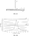
- Figure 2A is a diagram illustrating an example of the stylus 10, more specifically the electrode 27 at the tip of the stylus, being a first height or distance d1 from the stylus sensor 14 of the electronic device 12 according to one embodiment.
- Figure 2B is a diagram illustrating an example of a signal profile of a signal 31 received by sensing antennas of the stylus sensor 14 from the stylus 10 when the stylus 10 is a first distance d1 from the stylus sensor 14 according to one embodiment.
- FIG. 3A is a diagram illustrating an example of the stylus 10, more specifically the electrode 27 at the tip of the stylus, being a second height or distance d2 from the stylus sensor 14 of the electronic device 12 according to one embodiment.
- the second distance d2 is larger than the first distance d1.
- the first distance d1 may be between 0 and 10 millimeters
- the second distance d2 may be between 15 and 25 millimeters.
- Figure 3B is a diagram illustrating an example of a signal profile of a signal 33 received by sensing antennas of the stylus sensor 14 from the stylus 10 when the stylus is a second distance d2 from the stylus sensor 14 according to one embodiment. Similar to Figure 2B , eleven sensing antennas are shown along the x-axis of Figure 3B , and the strength of the signal 33 received by the sensing antennas is shown along the y-axis of Figure 3B .
- a strength of a signal received by the sensing antennas increases when the stylus 10 is closer to the stylus sensor 14.
- the strength of the signal 31 sensed by sensing antenna number 6 has a value of 0.18 when the stylus 10 is a first distance d1 from the stylus sensor 14, and the strength of the signal 33 sensed by sensing antenna number 6 has a value of under 0.02 when the stylus 10 is a second distance d2, which is larger than the first distance d1, from the stylus sensor 14.
- the strength of a signal transmitted between a stylus and a stylus sensor may be used as a proxy or indication for a distance between the stylus 10 and the stylus sensor 14.
- strength of a signal transmitted from the stylus 10 is dynamically adjusted based on a distance or height between the stylus 10 and the electronic device 12. Strength of a signal transmitted between the stylus 10 and the electronic device 12 is used as an indication of the distance or height. As will be discussed in further detail below, adjusting the strength of a signal transmitted from the stylus 10 increases the distance in which the stylus 10 may be detected, prevents oversaturation of the stylus sensor 14, and conserves power of the stylus 10.
- Figure 4 is a flow diagram illustrating an example of a process for adjusting signal strength of signals transmitted by the stylus 10 according to one embodiment.
- step 34 the process begins.
- step 36 a strength of a signal currently being transmitted between the stylus 10 and the electronic device 12 (i.e., a signal transmitted from the stylus 10 to the electronic device 12, or a signal transmitted from the electronic device 12 to the stylus 10) is measured.
- signal strength indicates how far the stylus 10 is from the electronic device 12.
- the measured signal strength of the signal currently being transmitted is indicative of the current position of the stylus 10 relative to the stylus sensor 14.
- the signal may be any signal that is transmitted between the stylus 10 and the electronic device 12.
- the signal may be a data signal sending stylus capability information, operational data, or a command.
- the strength of the signal may be any type of measurement that is indicative of signal strength, such as voltage, current, tesla, and volts per meter.
- the strength of the signal is measured by the stylus 10.
- a signal such as a command
- the communication module 30 of the stylus 10 is received by the communication module 30 of the stylus 10 from the electronic device 12, and the strength of the received signal is measured by the signal strength sensor 32.
- the strength of the signal is measured by the electronic device 12.
- a signal such as a beacon signal or a data signal
- the sensing antennas 15 of the stylus sensor 14 from the stylus 10
- the strength of the received signal is measured by the signal strength sensor 17.
- the electronic device 12 may either send commands based on the measured signal strength or data indicative of the signal strength to the stylus 10.
- the strength of the signal is measured based on a combination of the strength as measured by the stylus 10 and the strength as measured by the electronic device 12.
- step 38 it is determined whether the strength of the signal measured in step 36 is lower than or equal to a first threshold 40 (i.e., whether the stylus 10 and the electronic device 12 are distal to each other).
- a first threshold 40 i.e., whether the stylus 10 and the electronic device 12 are distal to each other.
- the first threshold 4o has a value of 0.1.
- the first threshold 40 is set according to a particular distance or height between the stylus 10 and the electronic device 12. In other words, the first threshold 40 is set to a value that corresponds to a particular distance, such as 20 millimeters, between the stylus 10 and the electronic device 12.
- the first threshold 40 is set based on the sensing capability of the stylus sensor 14. For example, the first threshold 40 may be set such that signal strengths below the second threshold 5o are not properly detected by the stylus sensor 14 and signal strengths above the second threshold 50 are properly detected by the stylus sensor 14.
- the strength of the signal is measured by the stylus 10.
- the determination of step 36 is performed by the stylus 10.
- the strength of the signal is measured by the electronic device 12.
- the determination of step 36 is performed by the electronic device 12.
- the strength of the signal measured in step 36 is not lower than the first threshold 40, it is assumed that the stylus 10 is in close proximity to the electronic device 12. For example, referring to Figure 2B , the strength of the signal 31 is larger than the first threshold 40 when the stylus 10 is a first distance d1 from the stylus sensor 14. The process then moves to step 42.
- step 36 If the strength of the signal measured in step 36 is lower than the first threshold 40, it is assumed that the stylus 10 is distal to the electronic device 12. For example, referring to Figure 3B , the strength of the signal 33 is less than the first threshold 40 when the stylus 10 is a second distance d2 from the stylus sensor 14. The process then moves to step 44.
- the strength of a signal transmitted by the stylus 10 is increased or boosted.
- the strength of the signal is increased by the gain controller 29.
- the stylus 10 may be detected by the electronic device 12 from greater distances.
- the strength of the signal is increased such that the electronic device 12 can detect the stylus 10 from at least 20 millimeters away.
- the increase in signal strength of the transmitted signal is chosen such that the increased signal strength will not saturate the receiving circuitry (e.g., the sensing elements 15) of the electronic device 12.
- the strength of the signal is measured by the stylus 10.
- the boosted signal is either a signal currently being transmitted by the stylus 10 or a subsequent signal transmitted by the stylus 10.
- the increasing of the strength of the signal transmitted by stylus 10 is initiated and performed by the stylus 10 itself.
- the strength of the signal is measured by the electronic device 12.
- the boosted signal is either the signal measured in step 36 or a subsequent signal transmitted by the stylus 10.
- the increasing of the strength of the signal transmitted by stylus 10 is initiated and performed by the electronic device 12.
- the electronic device 12 sends a command to the stylus 10 directing the stylus 10 to increase the strength of the signal.
- the electronic device 12 sends data indicative of the strength of the signal measured in step 36 to the stylus 10, and the stylus 10 increases the strength of the signal accordingly.
- the command and the data are sent via the sensor controller 16.
- the command and the data are collectively referred to as a height signal indicative of the height of the stylus 10 relative to the electronic device 12.
- the command is indicative of the height of the stylus 10 in that the command to increase or decrease the strength of the signal is indicative of the determined height of the stylus 10 being too high or too low, respectively.
- the data is indicative of the height of the stylus 10 in that the data indicative of a lower or higher measured strength of the signal is, in turn, indicative of the stylus 10 being too high or too low, respectively.
- the strength of the signal is increased in discrete steps. In another embodiment, the strength of the signal is increased continuously. When the strength of the signal is increased continuously, the relationship between received and transmitted signal strengths could be piecewise linear, linear, geometric, or some other transfer function between receiver and transmitter depending on implementation.
- a form of Automatic Gain Control is used to modulate transmitted signal strength based on the received signal.
- the gain signal from the AGC may be used as the transmit signal strength control. This is particularly useful for styli that retransmit a touch scan signal.
- the stylus 10 is in control of the signal strength.
- step 46 the stylus 10 transmits the boosted signal.
- the boosted signal is transmitted by the communication module 30 via the TX circuitry and the electrode 27. The process then moves to step 48.
- the electronic device 12 detects the transmitted signal from the stylus 10.
- the signal is sensed by the sensing elements 15 of the stylus sensor 14.
- the electronic device 12, more specifically the sensor controller 16 or the host processor 18, may perform a variety of actions in response.
- the electronic device 12 ignores other types of detections, such as a finger touch, by the stylus sensor 14 besides the boosted signal so that unintentional touches, such as a hand holding the stylus 10 or the electronic device 12, are not falsely detected.
- the process then returns to step 36, in which strength of a signal that is currently being transmitted between the stylus 10 and the electronic device is measured.
- step 42 it is determined whether the strength of the signal measured in step 36 is greater than or equal to a second threshold 50 (i.e., whether the stylus 10 and the electronic device 12 are in close proximity to each other) and are within an acceptable level.
- a second threshold 50 i.e., whether the stylus 10 and the electronic device 12 are in close proximity to each other
- the second threshold 50 has a value of 0.2.
- the second threshold 50 is set according to a distance between the stylus 10 and the electronic device 12. In other words, the second threshold 50 is set to a value that corresponds to a particular distance, such as 5 millimeters, between the stylus 10 and the electronic device 12.
- the second threshold 50 is set to avoid incorrect position measurement by the stylus sensor 14 caused by being overloaded or saturated by the signal transmitted by the stylus 10.
- the second threshold 50 may be set such that signal strengths below the second threshold 50 will not overload or saturate the stylus sensor 14, and signal strengths above the second threshold 50 may overload or saturate the stylus sensor 14.
- the second threshold 50 is set to conserve power of the stylus 10 and avoid excessive battery drain.
- the second threshold 50 may be set such that signal strengths below the second threshold 50 will not drain excessive power from the power source 20 and signal strengths above the second threshold 50 may drain excessive power from the power source 20.
- the strength of the signal is measured by the stylus 10.
- the determination of step 36 is performed by the stylus 10.
- the strength of the signal is measured by the electronic device 12.
- the determination of step 36 is performed by the electronic device 12.
- step 36 If the strength of the signal measured in step 36 is not greater than the second threshold 50, it is assumed that the stylus 10 and the electronic device 12 are not in close proximity to each other and the strength of the signal currently being transmitted by the stylus 10 is within an acceptable level. Accordingly, no action is taken and a current strength of a signal transmitted by the stylus 10 is maintained. The process then returns to step 36, in which strength of another or subsequent signal transmitted between the stylus 10 and the electronic device 12 is measured.
- step 36 If the strength of the signal measured in step 36 is greater than the second threshold 50, it is assumed that the stylus 10 and the electronic device 12 are in close proximity to each other and the strength of the signal currently being transmitted by the stylus 10 is not within an acceptable level. The process then moves to step 52.
- step 52 the strength of the signal transmitted by the stylus 10 is reduced and set to an appropriate strength level.
- the strength of the signal is reduced by the gain controller 29.
- the strength of the signal is measured by the stylus 10.
- the reduced signal is either a signal currently being transmitted by the stylus 10 or a subsequent signal transmitted by the stylus 10.
- the reduction of the strength of the signal transmitted by stylus 10 is initiated and performed by the stylus 10, itself.
- the strength of the signal is measured by the electronic device 12.
- the reduced signal is either the signal measured in step 36 or a subsequent signal transmitted by the stylus 10.
- the decreasing of the strength of the signal transmitted by stylus 10 is initiated and performed by the electronic device 12.
- the electronic device 12 sends a command to the stylus 10 directing the stylus 10 to decrease the strength of the signal.
- the electronic device 12 sends data indicative of the strength of the signal measured in step 36 to the stylus 10, and the stylus 10 decreases the strength of the signal accordingly.
- the command and the data are sent via the sensor controller 16.
- the strength of the signal is decreased in discrete steps. In another embodiment, the strength of the signal is decreased continuously. When the strength of the signal is increased continuously, the relationship between received and transmitted signal strengths could be piecewise linear, linear, geometric, or some other transfer function between receiver and transmitter depending on implementation.
- the second threshold 50 is larger than the first threshold 40.
- unnecessary increasing and decreasing of the strength of the signal transmitted by the stylus 10 may be avoided. For example, if a single threshold is used for both steps 38 and 42, a signal that fluctuates above and below the single threshold will have its strength oscillating between being decreased in step 42 and increased in step 44. By using two separate thresholds for steps 38 and 42, such alternating between increasing and decreasing of the signal can be mitigated or avoided.
- step 54 the stylus 10 transmits the reduced signal.
- the boosted signal is transmitted by the communication module 30 via the TX circuitry and the electrode 27.
- the process then moves to step 48.
- step 48 the electronic device 12 detects the transmitted signal from the stylus 10.
- the system and process for adjusting signal strength of signals transmitted by the stylus 10 improves detection of the stylus 10 at greater distances, prevents over saturation of the stylus sensor 14, and conserves power of the stylus 10.
- Increasing the distance in which a stylus may be detected by an electronic device is particularly beneficial for a stylus sensor that is capable of sensing a stylus and a finger touch.
- the electronic device may quicldy distinguish between a user using a stylus and a user using his or her finger, and respond accordingly. For example, once it is determined that a user is using a stylus, finger or hand touches by a user may be ignored. Accordingly, unintentional touches, such as a user's a hand holding the stylus or the electronic device, may be disregarded.
Landscapes
- Engineering & Computer Science (AREA)
- General Engineering & Computer Science (AREA)
- Theoretical Computer Science (AREA)
- Human Computer Interaction (AREA)
- Physics & Mathematics (AREA)
- General Physics & Mathematics (AREA)
- Measurement Of Length, Angles, Or The Like Using Electric Or Magnetic Means (AREA)
- Position Input By Displaying (AREA)
Abstract
Description
- This disclosure relates to improving detection of a stylus by an electronic device, such as a tablet based computing device or a tablet peripheral attached to a computing device.
- Many current styli include various electronic components that facilitate bidirectional communication (i.e., sending and receiving signals) with an electronic device, such as a tablet or mobile phone. For example, an electronic device may send a request for data from a stylus and the stylus may send the requested data. A location of a stylus on a surface of an electronic device may be determined based on a signal transmitted by the stylus. Namely, a control circuit in the electronic device may sequentially sample signals from the active stylus, and the location of the stylus may be determined based on the signal strengths of the sampled signals.
- Unfortunately, there is a limit as to how far away a stylus may be from an electronic device as signals sent or received between the stylus and the electronic device generally become weaker as the stylus moves further away from the electronic device. Attempting to overcome this by increasing the signal sent by the stylus often results in the receiving circuitry in the device becoming saturated when the stylus is near the surface. Accordingly, a stylus and an electronic device are typically unable to communicate unless they are in within close proximity of each other.
- The present disclosure is directed to a system and method for improving a distance or height in which a stylus may be detected by an electronic device, such as a computer, a tablet, and a smartphone, by adjusting signal strength of signals transmitted by the stylus.
- According to one embodiment, the system includes a stylus and an electronic device.
- The electronic device may include a stylus sensor, a sensor controller, a host processor, and a display. The stylus sensor includes a plurality of sensing antennas, such as loop coil antennas or line conductor antennas. The sensing antennas receive or detect signals from the stylus. The sensor controller controls the operation of the stylus sensor, performs bidirectional communication with the stylus, and communicates with the host processor. The host processor communicates with the sensor controller and executes a variety of applications or functions. The display is configured to display text or graphics. In one embodiment, the electronic device also includes a signal strength sensor that measures strengths of signals received by the sensing antennas from the stylus.
- The stylus may include a power source, an information manager, a data manager, sensors, buttons, a communication module, an electrode, and a gain controller housed by a body. The power source provides power to the stylus. The information manager may include a memory or cache that stores stylus capability information of the stylus. The data manager prepares operational data indicative of an operational state of the stylus, such as tip pressure data and orientation data. The sensors include one or more sensors, such as a stylus tip pressure sensor and a barrel sensor, which generates operational data of the stylus. The communication module provides bidirectional communication with the electronic device. The gain controller adjusts the gain or strength of signals transmitted by the TX circuitry of the communication module. In one embodiment, the stylus also includes a signal strength sensor that measures strengths of signals received by the RX circuitry of the communication module from the sensor controller.
- According to one embodiment, the method includes adjusting signal strength of signals transmitted by the stylus based on a distance between the stylus and the electronic device. Strength of a signal transmitted between a stylus and a stylus sensor is used as a proxy for the distance between the stylus and the electronic device. The method includes, in part, measuring strength of a signal currently being transmitted between the stylus and the electronic device (i.e., a signal transmitted from the stylus to the electronic device, and/or a signal transmitted from the electronic device to the stylus), and determining whether the measured strength of the signal corresponds to a first height value or a second height value, each indicative of a height of the stylus relative to the stylus sensor. For example, a threshold height is set, and the measured strength of the signal corresponding to a height at or below the threshold height is determined to correspond to the first height value, and the measured strength of the signal corresponding to a height above the threshold height is determined to correspond to the second height value. The method then includes adjusting the strength of the signal transmitted by the stylus to a first strength value in response to the determined first height value and to a second strength value different from the first strength value in response to the determined second height value. Thus, the transmit signal strength of the stylus is adjusted according to the determined height of the stylus relative to the stylus sensor (e.g., a greater transmit signal strength is used when the stylus is farther away from the stylus sensor) to thereby increase the detectable height of the stylus.
- In one embodiment, two thresholds are used to avoid having to switch (oscillate) between two transmit signal strengths too frequently. For example, the method includes determining whether the measured strength of the signal is lower than a first threshold. As before the strength of the signal may be measured by a signal strength sensor in the stylus and/or the electronic device.
- If the strength of the signal measured is lower than the first threshold, it is assumed that the stylus is farther away from the stylus sensor and, accordingly, the transmit signal strength may be increased from the first strength value to the second strength value. It is (e.g., subsequently) determined whether the measured strength of the signal is greater than a second threshold that is larger than the first threshold. If the measured strength of the signal is greater than the second threshold, it is assumed that the stylus is closer to the stylus sensor and, accordingly, the transmit signal strength may be decreased from the second strength value to the first strength value. If the measured strength of the signal is between the first (lower) threshold and the second (larger) threshold, the strength of the signal currently being transmitted by the stylus is within an acceptable level and the strength of the signal transmitted by the stylus is not adjusted.
- When the strength of the signal is measured by the stylus, the adjustment (increase and reduction) of the strength of the signal transmitted by the stylus is initiated by the stylus. When the strength of the signal is measured by the electronic device, the adjustment of the strength of the signal transmitted by stylus is initiated by the electronic device. In particular, the electronic device either sends a command to the stylus directing the stylus to increase or decrease the strength of the signal, or sends data indicative of the measured strength of the signal to the stylus and the stylus increases or decreases the strength of the signal accordingly. As used herein, the command and the data sent from the electronic device may be collectively referred to as a "height signal," which is indicative of the height of the stylus as determined by the electronic device.
- By reducing the strength of the signal transmitted by the stylus to an acceptable level, incorrect data from the stylus sensor caused by being overloaded or saturated by the signal transmitted by the stylus may be prevented and power may be conserved. Additionally or alternatively, by increasing or boosting the strength of the signal transmitted by the stylus to the acceptable level, the detectable height of the stylus may be increased, i.e., the stylus may be detected by the electronic device from greater distances.
- In the drawings, identical reference numbers identify similar elements. The sizes and relative positions of elements in the drawings are not necessarily drawn to scale.
-
Figure 1 is a diagram illustrating an example of a system including a stylus and an electronic device according to embodiments disclosed herein. -
Figure 2A is a diagram illustrating an example of a stylus being a first distance from a stylus sensor of an electronic device according to embodiments disclosed herein. -
Figure 2B is a diagram illustrating an example of a signal profile of a signal received by sensing antennas (sensor lines) of a stylus sensor from a stylus when the stylus is a first distance from the stylus sensor according to embodiments disclosed herein. -
Figure 3A is a diagram illustrating an example of a stylus being a second distance from a stylus sensor of an electronic device according to embodiments disclosed herein. -
Figure 3B is a diagram illustrating an example of a signal profile of a signal received by sensing antennas (sensor lines) of a stylus sensor from a stylus when the stylus is a second distance from the stylus sensor according to embodiments disclosed herein. -
Figure 4 is a flow diagram illustrating an example of a process for adjusting signal strength of signals transmitted by a stylus according to embodiments disclosed herein. - In the following description, for purposes of explanation, numerous specific details are set forth in order to provide a thorough understanding of the present invention. It will be evident, however, to one skilled in the art that the present invention may be practiced without these specific details. In other instances, well-known circuits, structures, and techniques are not shown in detail, but rather in a block diagram in order to avoid unnecessarily obscuring an understanding of this description. Thus, the specific details set forth are merely exemplary. Particular implementations may vary from these exemplary details and still be contemplated to be within the scope of the present invention. Reference in the description to "one embodiment" or "an embodiment" means that a particular feature, structure, or characteristic described in connection with the embodiment is included in at least one embodiment of the invention. The phrase "in one embodiment" located in various places in this description does not necessarily refer to the same embodiment.
-
FIG. 1 is a diagram illustrating an example of a system including astylus 10 and anelectronic device 12 according to one embodiment. - The
electronic device 12 may be any type of device that senses a stylus, such as a tablet, a personal computer, a tablet computer, and a smartphone. Theelectronic device 12 includes astylus sensor 14, asensor controller 16, asignal strength sensor 17, ahost processor 18, and adisplay 19. In another embodiment, thehost processor 18 and/or thedisplay 19 are external to the electronic device. - The
stylus sensor 14 includes a plurality ofsensing antennas 15, such as loop coil antennas or line conductor antennas. The sensing antennas (sensor lines) 15 receive or detect signals from thestylus 10. For example, theantennas 15 may be loop coil antennas configured to receive a magnetic field from thestylus 10, or line conductor antennas configured to receive an electrostatic field from thestylus 10. Thestylus sensor 14 may have any number of sensing antennas. In one embodiment, thesensing antennas 15 are arranged in a matrix of sensor lines extending in first and second directions different from each other. For example, thesensing antennas 15 may be arranged in array having a plurality of rows and columns. In one embodiment, thestylus sensor 14 is capable of detecting a passive stylus and a finger touch, in addition to thestylus 10. - The
sensor controller 16 controls the operation of thestylus sensor 14, performs bidirectional communication with thestylus 10, and communicates with thehost processor 18. In one embodiment, thesensor controller 16 processes handwritten input data from thestylus 10 to determine coordinates of a position indicated or pointed to by thestylus 10 on thestylus sensor 14, and forwards the coordinates to thehost processor 18. - The
signal strength sensor 17 measures strengths of signals received by thesensing antennas 15 from thestylus 10. Thesignal strength sensor 17 may be any type of sensor that obtains a measurement that is indicative of signal strength, such as voltage, current, tesla, and volts per meter. As will be discussed in further detail below, the strengths of the signals measured by thesignal strength sensor 17 are used to determine a location or coordinates of a tip of thestylus 10 on thestylus sensor 14. The strengths of the signals, including data signal, measured by thesignal strength sensor 17 are also used to adjust signal strengths of signals transmitted by thestylus 10. In one embodiment, thesignal strength sensor 17 is included in thesensor controller 16. - The
host processor 18 communicates with thesensor controller 16 and executes a variety of applications or functions. In one embodiment, thehost processor 18 receives coordinates from thesensor controller 16 and executes an application or function based on the received coordinates. Thesensor controller 16 and thehost processor 18 are connected via any suitable interface, such as the USB Human Interface Devices Protocol. In one embodiment, thehost processor 18 is a controller or CPU with memory. - The
display 19 is configured to display text or graphics. In one embodiment, thedisplay 19 displays text or graphics in response to thestylus 10 being detected by thestylus sensor 14. The display may be located above thestylus sensor 14 as shown inFigure 1 , thedisplay 19 may be located below thestylus sensor 14, or external to theelectronic device 12. - The
stylus 10 may be any stylus that contains active electronic components. Thestylus 10 includes apower source 20, aninformation manager 22, adata manager 24,sensors 26,buttons 28, acommunication module 30, anelectrode 27, asignal strength sensor 32, and again controller 29. Thepower source 20, theinformation manager 22, thedata manager 24,sensors 26, thebuttons 28, thecommunication module 30, anelectrode 27, thesignal strength sensor 32, and thegain controller 29 are housed by abody 35. In one embodiment, thebody 35 has an elongated shape. - The
power source 20 may be any type of a power source, such as a battery or a parasitic energy conduit, that provides power to thestylus 10. - The
information manager 22 includes a memory or cache that stores stylus capability information of thestylus 10. The stylus capability information may include information indicating an operational state of thestylus 10. The stylus capability information may include information regarding predefined capabilities of the stylus and setting information regarding user-adjustable setting of the stylus. Theinformation manager 22 updates the setting information each time a user changes the stylus setting, such as the stylus color and stylus line width. - The
data manager 24 prepares operational data indicative of an operational state of thestylus 10, such as tip pressure data, buttons states, and orientation data (e.g., data indicating how much thestylus 10 is twisted or tilted relative to a surface of the stylus sensor 14). - The
sensors 26 include one or more sensors, such as a stylus tip pressure sensor (e.g., a variable capacitor) configured to sense pressure applied to the stylus tip; a barrel pressure sensor configured to sense pressure applied to the stylus barrel; a 9-axis or lesser-axis IMU (inertial measurement unit) including one or more combinations of 3-axis gyroscopes, 3-axis accelerometers, and 3-axis magnetometers; a twist sensor configured to sense twist/rotation of thestylus 10; and a tilt sensor configured to sense X and Y directional tilt of an axis of thestylus 10 relative to a surface of thestylus sensor 14. Thesensors 26 generate operational data of thestylus 10, such as stylus tip pressure data, stylus barrel pressure data, stylus orientation (e.g., twist or tilt) data, stylus switch status, and stylus battery level. - The
buttons 28 allow the user to configure or adjust thestylus 10. For example, a user may use thebuttons 28 to update setting information, such as the stylus color and stylus line width. Thebuttons 28 also allow the user to send instructions or commands to thesensor controller 16. For instance, a user may use thebuttons 28 to indicate a right click command to theelectronic device 12 similar to a computer mouse. Thestylus 10 may include any number of buttons and may be positioned anywhere on thebody 35. Thebuttons 28 may also be replaced with other types of mechanical inputs, such as switches, knobs, etc. - The
information manager 22 and thedata manager 24 are both coupled to thecommunication module 30. Thecommunication module 30 is capable of bidirectional communication with theelectronic device 12. In one embodiment, thecommunication module 30 includes transmission (TX) and reception (RX) circuitry that communicates with theelectronic device 12 through theelectrode 27. Theelectrode 27 is typically used to electromagnetically or electrostatically communicate with thesensor lines 15 of thestylus sensor 14. In the same or another embodiment, thecommunication module 30 includes a transmitter and a receiver, or a transceiver, specific to a particular communication protocol. The communication module may utilize any one or more types of communication protocols, such as a protocol based on electromagnetic communication, a protocol based on electrostatic communication, any RF communication protocol such as Bluetooth®. The TX and RX circuitry are sometimes referred to as a signal generator and a signal receiver, respectively. - The
communication module 30 transmits or generates stylus capability information and operational data to thesensor controller 16. As previously discussed, stylus capability information may include information regarding predefined capabilities of the stylus and setting information regarding user-adjustable settings of the stylus; and operational data may include data such as stylus tip pressure data, stylus barrel pressure data, stylus orientation (e.g., twist or tilt) data, stylus switch status, and stylus battery level. Thecommunication module 30 may transmit the stylus capability information and operational data via the TX circuitry and theelectrode 27, or a transceiver/transmitter specific to a communication protocol (e.g., Bluetooth®). - The
communication module 30 receives various commands and other information from thesensor controller 16. The commands may include various commands, such as a read command to request thestylus 10 to transmit stylus capability information to thesensor controller 16, a write command to configure capability information for thestylus 10, and a polling command to request thestylus 10 to transmit operational data of the active stylus to thesensor controller 16. Thecommunication module 30 may receive the various commands and other information via the RX circuitry and theelectrode 27, or transceiver/receiver specific to a communication protocol (e.g., Bluetooth®). - Signals transmitted or received by the
communication module 40 are transmitted or received through the electrode 27 (and via a separate transmitter/receiver specific to a particular communication protocol, if provided as described above). In one embodiment, as shown inFigure 1 , theelectrode 27 is positioned at or near a tip of thebody 35. - The
signal strength sensor 32 measures strengths of signals received by the RX circuitry, such as signals transmitted from thesensor controller 16. Thesignal strength sensor 32 may be any type of sensor that obtains a measurement that is indicative of signal strength, such as voltage, current, tesla, and volts per meter. As will be discussed in further detail below, the strengths of the signals measured by thesignal strength sensor 32 are used to adjust signal strengths of signals transmitted by thestylus 10. In one embodiment, signalstrength sensor 32 is included in thegain controller 29. - The
gain controller 29 adjusts the gain or strength of signals transmitted by thestylus 10, more specifically thecommunication module 30. As will be discussed in further detail below, thegain controller 29 dynamically adjusts a strength of a signal transmitted by thestylus 10 based on a strength of a signal transmitted between thestylus 10 and theelectronic device 12. - In one embodiment, signals (e.g., beacon signals, tones, or data signals including stylus capability information and operational data) transmitted by the
communication module 30 of thestylus 10 are used to determine a location or coordinates of a tip of thestylus 10 onstylus sensor 14 of theelectronic device 12. In particular, thesignal strength sensor 17 measures strengths of signals detected or received by thesensing antennas 15 from thecommunication module 30. Thesensor controller 16 then uses the variation of signal strengths over the antennas to interpolate a precise location of a tip of thestylus 10. In one embodiment, the location of thestylus 10 is determined to be near an antenna in which the signal strength is the strongest, as signal strength is typically the strongest in an antenna proximate to thestylus 10 and decreases in antennas further away from thestylus 10. In the same or another embodiment, thesensor controller 16 uses interpolation algorithms that use the strength of two or more antennas nearest to the stylus to improve the resolution of the measured location beyond the antenna spacing. - In general, the strength of signals received by the
stylus 10 from theelectronic device 12 or signals received by theelectronic device 12 from thestylus 10 is stronger when thestylus 10 and theelectronic device 12 are in close proximity to each other, and is weaker the further away thestylus 10 and theelectronic device 12 are from each other. For example,Figure 2A is a diagram illustrating an example of thestylus 10, more specifically theelectrode 27 at the tip of the stylus, being a first height or distance d1 from thestylus sensor 14 of theelectronic device 12 according to one embodiment.Figure 2B is a diagram illustrating an example of a signal profile of asignal 31 received by sensing antennas of thestylus sensor 14 from thestylus 10 when thestylus 10 is a first distance d1 from thestylus sensor 14 according to one embodiment. Eleven sensing antennas are shown along the x-axis ofFigure 2B , and the strength of thesignal 31 received by the sensing antennas are shown along the y-axis ofFigure 2B . The strengths of the received signals may be in terms of any type of unit indicative of signal strength, such as voltage, current, tesla, and volts per meter.Figure 3A is a diagram illustrating an example of thestylus 10, more specifically theelectrode 27 at the tip of the stylus, being a second height or distance d2 from thestylus sensor 14 of theelectronic device 12 according to one embodiment. The second distance d2 is larger than the first distance d1. For example, the first distance d1 may be between 0 and 10 millimeters, and the second distance d2 may be between 15 and 25 millimeters.Figure 3B is a diagram illustrating an example of a signal profile of asignal 33 received by sensing antennas of thestylus sensor 14 from thestylus 10 when the stylus is a second distance d2 from thestylus sensor 14 according to one embodiment. Similar toFigure 2B , eleven sensing antennas are shown along the x-axis ofFigure 3B , and the strength of thesignal 33 received by the sensing antennas is shown along the y-axis ofFigure 3B . - By comparing
Figures 2B and3B , it can be seen that a strength of a signal received by the sensing antennas increases when thestylus 10 is closer to thestylus sensor 14. For example, the strength of thesignal 31 sensed by sensingantenna number 6 has a value of 0.18 when thestylus 10 is a first distance d1 from thestylus sensor 14, and the strength of thesignal 33 sensed by sensingantenna number 6 has a value of under 0.02 when thestylus 10 is a second distance d2, which is larger than the first distance d1, from thestylus sensor 14. - Accordingly, the strength of a signal transmitted between a stylus and a stylus sensor may be used as a proxy or indication for a distance between the
stylus 10 and thestylus sensor 14. - In one embodiment, strength of a signal transmitted from the
stylus 10 is dynamically adjusted based on a distance or height between thestylus 10 and theelectronic device 12. Strength of a signal transmitted between thestylus 10 and theelectronic device 12 is used as an indication of the distance or height. As will be discussed in further detail below, adjusting the strength of a signal transmitted from thestylus 10 increases the distance in which thestylus 10 may be detected, prevents oversaturation of thestylus sensor 14, and conserves power of thestylus 10. -
Figure 4 is a flow diagram illustrating an example of a process for adjusting signal strength of signals transmitted by thestylus 10 according to one embodiment. - In
step 34, the process begins. Instep 36, a strength of a signal currently being transmitted between thestylus 10 and the electronic device 12 (i.e., a signal transmitted from thestylus 10 to theelectronic device 12, or a signal transmitted from theelectronic device 12 to the stylus 10) is measured. As previously discussed, signal strength indicates how far thestylus 10 is from theelectronic device 12. Accordingly, the measured signal strength of the signal currently being transmitted is indicative of the current position of thestylus 10 relative to thestylus sensor 14. The signal may be any signal that is transmitted between thestylus 10 and theelectronic device 12. For example, as previously discussed, the signal may be a data signal sending stylus capability information, operational data, or a command. As previously discussed, the strength of the signal may be any type of measurement that is indicative of signal strength, such as voltage, current, tesla, and volts per meter. - In one embodiment, the strength of the signal is measured by the
stylus 10. For example, a signal, such as a command, is received by thecommunication module 30 of thestylus 10 from theelectronic device 12, and the strength of the received signal is measured by thesignal strength sensor 32. - In another embodiment, the strength of the signal is measured by the
electronic device 12. For example, a signal, such as a beacon signal or a data signal, is received by thesensing antennas 15 of thestylus sensor 14 from thestylus 10, and the strength of the received signal is measured by thesignal strength sensor 17. As will be discussed in further detail below, in this embodiment, theelectronic device 12 may either send commands based on the measured signal strength or data indicative of the signal strength to thestylus 10. - In a further embodiment, the strength of the signal is measured based on a combination of the strength as measured by the
stylus 10 and the strength as measured by theelectronic device 12. - In
step 38, it is determined whether the strength of the signal measured instep 36 is lower than or equal to a first threshold 40 (i.e., whether thestylus 10 and theelectronic device 12 are distal to each other). InFigures 2B and3B , for example, the first threshold 4o has a value of 0.1. In one embodiment, thefirst threshold 40 is set according to a particular distance or height between thestylus 10 and theelectronic device 12. In other words, thefirst threshold 40 is set to a value that corresponds to a particular distance, such as 20 millimeters, between thestylus 10 and theelectronic device 12. In another embodiment, thefirst threshold 40 is set based on the sensing capability of thestylus sensor 14. For example, thefirst threshold 40 may be set such that signal strengths below the second threshold 5o are not properly detected by thestylus sensor 14 and signal strengths above thesecond threshold 50 are properly detected by thestylus sensor 14. - In one embodiment, as previously discussed, the strength of the signal is measured by the
stylus 10. In this embodiment, the determination ofstep 36 is performed by thestylus 10. - In another embodiment, as previously discussed, the strength of the signal is measured by the
electronic device 12. In this embodiment, the determination ofstep 36 is performed by theelectronic device 12. - If the strength of the signal measured in
step 36 is not lower than thefirst threshold 40, it is assumed that thestylus 10 is in close proximity to theelectronic device 12. For example, referring toFigure 2B , the strength of thesignal 31 is larger than thefirst threshold 40 when thestylus 10 is a first distance d1 from thestylus sensor 14. The process then moves to step 42. - If the strength of the signal measured in
step 36 is lower than thefirst threshold 40, it is assumed that thestylus 10 is distal to theelectronic device 12. For example, referring toFigure 3B , the strength of thesignal 33 is less than thefirst threshold 40 when thestylus 10 is a second distance d2 from thestylus sensor 14. The process then moves to step 44. - In
step 44, the strength of a signal transmitted by thestylus 10 is increased or boosted. The strength of the signal is increased by thegain controller 29. By increasing or boosting the strength of the signal, thestylus 10 may be detected by theelectronic device 12 from greater distances. In one embodiment, the strength of the signal is increased such that theelectronic device 12 can detect thestylus 10 from at least 20 millimeters away. In the same or another embodiment, the increase in signal strength of the transmitted signal is chosen such that the increased signal strength will not saturate the receiving circuitry (e.g., the sensing elements 15) of theelectronic device 12. - In one embodiment, as previously discussed, the strength of the signal is measured by the
stylus 10. In this embodiment, the boosted signal is either a signal currently being transmitted by thestylus 10 or a subsequent signal transmitted by thestylus 10. In addition, the increasing of the strength of the signal transmitted bystylus 10 is initiated and performed by thestylus 10 itself. - In another embodiment, as previously discussed, the strength of the signal is measured by the
electronic device 12. In this embodiment, the boosted signal is either the signal measured instep 36 or a subsequent signal transmitted by thestylus 10. In addition, the increasing of the strength of the signal transmitted bystylus 10 is initiated and performed by theelectronic device 12. In particular, in one embodiment, theelectronic device 12 sends a command to thestylus 10 directing thestylus 10 to increase the strength of the signal. In another embodiment, theelectronic device 12 sends data indicative of the strength of the signal measured instep 36 to thestylus 10, and thestylus 10 increases the strength of the signal accordingly. The command and the data are sent via thesensor controller 16. In some embodiments, the command and the data are collectively referred to as a height signal indicative of the height of thestylus 10 relative to theelectronic device 12. The command is indicative of the height of thestylus 10 in that the command to increase or decrease the strength of the signal is indicative of the determined height of thestylus 10 being too high or too low, respectively. The data is indicative of the height of thestylus 10 in that the data indicative of a lower or higher measured strength of the signal is, in turn, indicative of thestylus 10 being too high or too low, respectively. - In one embodiment, the strength of the signal is increased in discrete steps. In another embodiment, the strength of the signal is increased continuously. When the strength of the signal is increased continuously, the relationship between received and transmitted signal strengths could be piecewise linear, linear, geometric, or some other transfer function between receiver and transmitter depending on implementation.
- In one embodiment, a form of Automatic Gain Control (AGC) is used to modulate transmitted signal strength based on the received signal. For example, the gain signal from the AGC may be used as the transmit signal strength control. This is particularly useful for styli that retransmit a touch scan signal. In this embodiment, the
stylus 10 is in control of the signal strength. - In
step 46, thestylus 10 transmits the boosted signal. The boosted signal is transmitted by thecommunication module 30 via the TX circuitry and theelectrode 27. The process then moves to step 48. - In
step 48, theelectronic device 12 detects the transmitted signal from thestylus 10. The signal is sensed by thesensing elements 15 of thestylus sensor 14. Upon the signal being detected by theelectronic device 12, theelectronic device 12, more specifically thesensor controller 16 or thehost processor 18, may perform a variety of actions in response. In one embodiment, theelectronic device 12 ignores other types of detections, such as a finger touch, by thestylus sensor 14 besides the boosted signal so that unintentional touches, such as a hand holding thestylus 10 or theelectronic device 12, are not falsely detected. The process then returns to step 36, in which strength of a signal that is currently being transmitted between thestylus 10 and the electronic device is measured. - Returning to step 38, if the strength of the signal is not lower than the
first threshold 40, the process moves to step 42. Instep 42, it is determined whether the strength of the signal measured instep 36 is greater than or equal to a second threshold 50 (i.e., whether thestylus 10 and theelectronic device 12 are in close proximity to each other) and are within an acceptable level. InFigures 2B and3B , for example, thesecond threshold 50 has a value of 0.2. In one embodiment, thesecond threshold 50 is set according to a distance between thestylus 10 and theelectronic device 12. In other words, thesecond threshold 50 is set to a value that corresponds to a particular distance, such as 5 millimeters, between thestylus 10 and theelectronic device 12. In another embodiment, thesecond threshold 50 is set to avoid incorrect position measurement by thestylus sensor 14 caused by being overloaded or saturated by the signal transmitted by thestylus 10. For example, thesecond threshold 50 may be set such that signal strengths below thesecond threshold 50 will not overload or saturate thestylus sensor 14, and signal strengths above thesecond threshold 50 may overload or saturate thestylus sensor 14. In another embodiment, thesecond threshold 50 is set to conserve power of thestylus 10 and avoid excessive battery drain. For instance, thesecond threshold 50 may be set such that signal strengths below thesecond threshold 50 will not drain excessive power from thepower source 20 and signal strengths above thesecond threshold 50 may drain excessive power from thepower source 20. - In one embodiment, as previously discussed, the strength of the signal is measured by the
stylus 10. In this embodiment, the determination ofstep 36 is performed by thestylus 10. - In another embodiment, as previously discussed, the strength of the signal is measured by the
electronic device 12. In this embodiment, the determination ofstep 36 is performed by theelectronic device 12. - If the strength of the signal measured in
step 36 is not greater than thesecond threshold 50, it is assumed that thestylus 10 and theelectronic device 12 are not in close proximity to each other and the strength of the signal currently being transmitted by thestylus 10 is within an acceptable level. Accordingly, no action is taken and a current strength of a signal transmitted by thestylus 10 is maintained. The process then returns to step 36, in which strength of another or subsequent signal transmitted between thestylus 10 and theelectronic device 12 is measured. - If the strength of the signal measured in
step 36 is greater than thesecond threshold 50, it is assumed that thestylus 10 and theelectronic device 12 are in close proximity to each other and the strength of the signal currently being transmitted by thestylus 10 is not within an acceptable level. The process then moves to step 52. - In
step 52, the strength of the signal transmitted by thestylus 10 is reduced and set to an appropriate strength level. The strength of the signal is reduced by thegain controller 29. By reducing the strength of the signal transmitted by thestylus 10, incorrect position measurement by thestylus sensor 14 caused by being overloaded or saturated by the signal transmitted by thestylus 10 may be prevented, and power may be conserved. - In one embodiment, as previously discussed, the strength of the signal is measured by the
stylus 10. In this embodiment, the reduced signal is either a signal currently being transmitted by thestylus 10 or a subsequent signal transmitted by thestylus 10. In addition, the reduction of the strength of the signal transmitted bystylus 10 is initiated and performed by thestylus 10, itself. - In another embodiment, as previously discussed, the strength of the signal is measured by the
electronic device 12. In this embodiment, the reduced signal is either the signal measured instep 36 or a subsequent signal transmitted by thestylus 10. In addition, the decreasing of the strength of the signal transmitted bystylus 10 is initiated and performed by theelectronic device 12. In particular, in one embodiment, theelectronic device 12 sends a command to thestylus 10 directing thestylus 10 to decrease the strength of the signal. In another embodiment, theelectronic device 12 sends data indicative of the strength of the signal measured instep 36 to thestylus 10, and thestylus 10 decreases the strength of the signal accordingly. The command and the data are sent via thesensor controller 16. - In one embodiment, the strength of the signal is decreased in discrete steps. In another embodiment, the strength of the signal is decreased continuously. When the strength of the signal is increased continuously, the relationship between received and transmitted signal strengths could be piecewise linear, linear, geometric, or some other transfer function between receiver and transmitter depending on implementation.
- In one embodiment, the
second threshold 50 is larger than thefirst threshold 40. By utilizing two different values for thefirst threshold 40 and thesecond threshold 50, unnecessary increasing and decreasing of the strength of the signal transmitted by thestylus 10 may be avoided. For example, if a single threshold is used for bothsteps step 42 and increased instep 44. By using two separate thresholds forsteps - In
step 54, thestylus 10 transmits the reduced signal. The boosted signal is transmitted by thecommunication module 30 via the TX circuitry and theelectrode 27. The process then moves to step 48. As discussed above, instep 48, theelectronic device 12 detects the transmitted signal from thestylus 10. - In accordance with one or more embodiments, the system and process for adjusting signal strength of signals transmitted by the
stylus 10 improves detection of thestylus 10 at greater distances, prevents over saturation of thestylus sensor 14, and conserves power of thestylus 10. Increasing the distance in which a stylus may be detected by an electronic device is particularly beneficial for a stylus sensor that is capable of sensing a stylus and a finger touch. By detecting a stylus well above a surface of a stylus sensor, the electronic device may quicldy distinguish between a user using a stylus and a user using his or her finger, and respond accordingly. For example, once it is determined that a user is using a stylus, finger or hand touches by a user may be ignored. Accordingly, unintentional touches, such as a user's a hand holding the stylus or the electronic device, may be disregarded. - The various embodiments described above can be combined to provide further embodiments. These and other changes can be made to the embodiments in light of the above-detailed description. In general, in the following claims, the terms used should not be construed to limit the claims to the specific embodiments disclosed in the specification and the claims, but should be construed to include all possible embodiments along with the full scope of equivalents to which such claims are entitled. Accordingly, the claims are not limited by the disclosure.
Claims (15)
- An active stylus, comprising:a body including an electrode;a signal generator coupled to the electrode to transmit a signal from the electrode; anda gain controller configured to:receive a control signal indicative of a height of the electrode relative to a surface of a sensor including a matrix of sensor lines extending in first and second directions different from each other; andset a transmit signal strength of the signal transmitted from the electrode to a first strength value when the control signal indicates a first height value, and to a second strength value when the signal indicates a second height value.
- The active stylus of Claim 1, wherein the first strength value is lower than the second strength value and the first height value is lower than the second height value,
and/or
wherein the first height value is at or below a threshold height and the second height value exceeds the threshold height. - The active stylus of Claim 1 or 2, wherein the gain controller is configured to discretely vary the transmit signal strength in a step between the first strength value and the second strength value,
or
wherein the gain controller is configured to continuously vary the transmit signal strength between the first strength value and the second strength value corresponding to continuously varying heights of the active stylus. - The active stylus according to one of the preceding claims, wherein the height of the electrode is indicated from one or both of a strength of a sensor signal received by the active stylus and a strength of a stylus signal received by the sensor.
- The active stylus according to one of the preceding claims, wherein the gain controller is configured to indicate the height of the electrode based on a sensor signal received by the active stylus,
preferably
based on a height signal received by the active stylus, wherein the height signal indicates a height of the active stylus indicated by a sensor controller coupled to the sensor based on a stylus signal received by the sensor. - The active stylus of Claim 5, wherein the electrode of the active stylus receives the height signal from the sensor, preferably electrostatically,
the active stylus preferably further comprising a receiver configured to receive the height signal from the sensor. - The active stylus according to one of the preceding claims, wherein the gain controller is configured to:change the transmit signal strength from the first strength value to the second strength value when it is indicated that the height crosses a first threshold; andchange the transmit signal strength from the second strength value to the first strength value when it is indicated that the height crosses a second threshold.
- The active stylus of Claim 7, wherein the first strength value is lower than the second strength value and the first height value is lower than the second height value, the first threshold is lower than the second threshold, and the gain controller is configured to:increase the transmit signal strength from the first strength value to the second strength value when the height exceeds the first threshold;decrease the transmit signal strength from the second strength value to the first strength value when the height falls below the second threshold; andmaintain the transmit signal strength when the height is between the first threshold and the second threshold.
- The active stylus according to one of the preceding claims, wherein the body has an elongate shape and the electrode is provided at or near a tip of the elongate body.
- A method for detecting a position of an active stylus, which includes an electrode, on a sensor which includes a matrix of sensor lines extending in first and second directions different from each other, the method comprising:receiving a control signal indicative of a height of the electrode relative to a surface of the sensor; andsetting a transmit signal strength of a signal transmitted from the electrode of the active stylus to a first strength value when the control signal indicates a first height value, and to a second strength value when the control signal indicates a second height value.
- The method of Claim 16, comprising discretely varying the transmit signal strength in a step between the first strength value and the second strength value,
or comprising continuously varying the transmit signal strength between the first strength value and the second strength value corresponding to continuously varying heights of the active stylus. - The method of Claim 10 or 11, wherein the height of the electrode is indicated from one or both of a strength of a sensor signal received by the active stylus and a strength of a stylus signal received by the sensor.
- The method of one of the Claims 10 to 12, comprising indicating the height of the electrode based on a sensor signal received by the active stylus,
preferably
based on a height signal received by the active stylus, wherein the height signal indicates a height of the active stylus indicated by a sensor controller coupled to the sensor based on a stylus signal received by the sensor. - A sensor controller to be coupled to a sensor including a matrix of sensor lines extending in first and second directions different from each other, the sensor controller comprising:a reception/transmission controller configured to control electrostatic reception and transmission of signals from and to an electrode of an active stylus; anda processor comprising circuitry and configured to:receive a control signal indicative of a height of the active stylus relative to a surface of the sensor based on stylus signals electrostatically received by the matrix of sensor lines, anddirect the reception/transmission controller to transmit a height signal to the active stylus, wherein the height signal indicates the height of the active stylus.
- The sensor controller of Claim 14, wherein the reception/transmission controller is configured to control transmission of the height signal to the active stylus using a wireless communication protocol,
and/or
wherein the reception/transmission controller is configured to control reception of stylus signals transmitted from the electrode of the active stylus at a first transmit signal strength value when the active stylus is at a first height value, and stylus signals transmitted from the electrode of the active stylus at a second strength value when the active stylus is at a second height value.
Applications Claiming Priority (1)
| Application Number | Priority Date | Filing Date | Title |
|---|---|---|---|
| US15/345,943 US10073548B2 (en) | 2016-11-08 | 2016-11-08 | Stylus having variable transmit signal strength, and sensor for detecting such stylus |
Publications (2)
| Publication Number | Publication Date |
|---|---|
| EP3318962A1 true EP3318962A1 (en) | 2018-05-09 |
| EP3318962B1 EP3318962B1 (en) | 2021-06-23 |
Family
ID=60268264
Family Applications (1)
| Application Number | Title | Priority Date | Filing Date |
|---|---|---|---|
| EP17200093.7A Active EP3318962B1 (en) | 2016-11-08 | 2017-11-06 | Stylus having variable transmit signal strength |
Country Status (6)
| Country | Link |
|---|---|
| US (1) | US10073548B2 (en) |
| EP (1) | EP3318962B1 (en) |
| JP (1) | JP6971083B2 (en) |
| KR (1) | KR102384569B1 (en) |
| CN (1) | CN108062173B (en) |
| TW (1) | TWI749023B (en) |
Cited By (3)
| Publication number | Priority date | Publication date | Assignee | Title |
|---|---|---|---|---|
| EP3640775A4 (en) * | 2018-09-05 | 2020-07-22 | Shenzhen Goodix Technology Co., Ltd. | TOUCH MEASUREMENT METHOD, TOUCH CHIP, ELECTRONIC DEVICE AND TOUCH SYSTEM |
| WO2020256845A1 (en) * | 2019-06-19 | 2020-12-24 | Microsoft Technology Licensing, Llc | Adaptive hover operation of touch instruments |
| CN113885724A (en) * | 2020-07-01 | 2022-01-04 | 株式会社和冠 | Position detection device and position detection method |
Families Citing this family (8)
| Publication number | Priority date | Publication date | Assignee | Title |
|---|---|---|---|---|
| EP4080333B1 (en) | 2017-11-29 | 2024-07-17 | Wacom Co., Ltd. | Active pen |
| CN121957360A (en) * | 2018-05-18 | 2026-05-01 | 株式会社和冠 | Position indication device, computer and control method |
| KR102724467B1 (en) | 2019-07-26 | 2024-11-01 | 삼성전자 주식회사 | Electronic device and method for controlling digitizer panel of electronic device based on status of electronic pen thereof |
| KR102895819B1 (en) * | 2020-07-23 | 2025-12-05 | 삼성디스플레이 주식회사 | Input device and the interface device including the same |
| US11775084B2 (en) * | 2021-04-20 | 2023-10-03 | Microsoft Technology Licensing, Llc | Stylus haptic component arming and power consumption |
| JP2023183222A (en) * | 2022-06-15 | 2023-12-27 | 株式会社ワコム | Position detection circuit, position detection method, and position detection system |
| CN115437488B (en) * | 2022-09-16 | 2025-12-12 | 维沃移动通信有限公司 | Power saving methods, devices, electronic equipment and media |
| CN117724618B (en) * | 2023-07-05 | 2024-12-27 | 荣耀终端有限公司 | Film identification method and electronic equipment |
Citations (3)
| Publication number | Priority date | Publication date | Assignee | Title |
|---|---|---|---|---|
| US20100066693A1 (en) * | 2008-09-12 | 2010-03-18 | Mitsubishi Electric Corporation | Touch panel device |
| WO2015191807A1 (en) * | 2014-06-12 | 2015-12-17 | Amazon Technologies, Inc. | Configurable active stylus devices |
| US20160266663A1 (en) * | 2015-03-09 | 2016-09-15 | Eivind Holsen | Adaptive Transmit Voltage in Active Stylus |
Family Cites Families (11)
| Publication number | Priority date | Publication date | Assignee | Title |
|---|---|---|---|---|
| US7298367B2 (en) * | 2003-11-25 | 2007-11-20 | 3M Innovative Properties Company | Light emitting stylus and user input device using same |
| US9195351B1 (en) * | 2011-09-28 | 2015-11-24 | Amazon Technologies, Inc. | Capacitive stylus |
| KR20140017255A (en) * | 2012-07-31 | 2014-02-11 | 삼성전자주식회사 | Electric pen input recognition apparatus and method using c-type tsp |
| US9841862B2 (en) * | 2012-10-16 | 2017-12-12 | Atmel Corporation | Stylus position system |
| TWI579736B (en) * | 2014-05-13 | 2017-04-21 | 禾瑞亞科技股份有限公司 | Transmitter, touch sensitive processing apparatus and controlling method thereof and touch sensitive system |
| TWI605360B (en) * | 2014-05-27 | 2017-11-11 | 禾瑞亞科技股份有限公司 | Touch processor, touch device, touch system and touch method |
| CN115963922B (en) * | 2014-09-02 | 2026-04-07 | 苹果公司 | Semantic framework for variable haptic output |
| US9575573B2 (en) * | 2014-12-18 | 2017-02-21 | Apple Inc. | Stylus with touch sensor |
| JP6487694B2 (en) * | 2014-12-26 | 2019-03-20 | 株式会社ワコム | Position indicator and signal processing device |
| JP6544791B2 (en) * | 2015-02-20 | 2019-07-17 | 株式会社ワコム | Position indicator, signal processing circuit, signal supply control method and signal processing method |
| US9841828B2 (en) * | 2016-04-20 | 2017-12-12 | Microsoft Technology Licensing, Llc | Pressure sensitive stylus |
-
2016
- 2016-11-08 US US15/345,943 patent/US10073548B2/en active Active
-
2017
- 2017-06-28 TW TW106121636A patent/TWI749023B/en active
- 2017-07-27 CN CN201710622929.1A patent/CN108062173B/en active Active
- 2017-08-14 JP JP2017156317A patent/JP6971083B2/en active Active
- 2017-10-17 KR KR1020170134880A patent/KR102384569B1/en active Active
- 2017-11-06 EP EP17200093.7A patent/EP3318962B1/en active Active
Patent Citations (3)
| Publication number | Priority date | Publication date | Assignee | Title |
|---|---|---|---|---|
| US20100066693A1 (en) * | 2008-09-12 | 2010-03-18 | Mitsubishi Electric Corporation | Touch panel device |
| WO2015191807A1 (en) * | 2014-06-12 | 2015-12-17 | Amazon Technologies, Inc. | Configurable active stylus devices |
| US20160266663A1 (en) * | 2015-03-09 | 2016-09-15 | Eivind Holsen | Adaptive Transmit Voltage in Active Stylus |
Cited By (4)
| Publication number | Priority date | Publication date | Assignee | Title |
|---|---|---|---|---|
| EP3640775A4 (en) * | 2018-09-05 | 2020-07-22 | Shenzhen Goodix Technology Co., Ltd. | TOUCH MEASUREMENT METHOD, TOUCH CHIP, ELECTRONIC DEVICE AND TOUCH SYSTEM |
| US10996802B2 (en) | 2018-09-05 | 2021-05-04 | Shenzhen GOODIX Technology Co., Ltd. | Touch sensing method, touch chip, electronic device and touch system |
| WO2020256845A1 (en) * | 2019-06-19 | 2020-12-24 | Microsoft Technology Licensing, Llc | Adaptive hover operation of touch instruments |
| CN113885724A (en) * | 2020-07-01 | 2022-01-04 | 株式会社和冠 | Position detection device and position detection method |
Also Published As
| Publication number | Publication date |
|---|---|
| EP3318962B1 (en) | 2021-06-23 |
| KR102384569B1 (en) | 2022-04-08 |
| TWI749023B (en) | 2021-12-11 |
| TW201818202A (en) | 2018-05-16 |
| JP6971083B2 (en) | 2021-11-24 |
| US20180129305A1 (en) | 2018-05-10 |
| CN108062173A (en) | 2018-05-22 |
| KR20180051368A (en) | 2018-05-16 |
| JP2018077826A (en) | 2018-05-17 |
| CN108062173B (en) | 2023-04-11 |
| US10073548B2 (en) | 2018-09-11 |
Similar Documents
| Publication | Publication Date | Title |
|---|---|---|
| US10073548B2 (en) | Stylus having variable transmit signal strength, and sensor for detecting such stylus | |
| KR102358217B1 (en) | Stylus tilt detection based on bidirectional communication between stylus and stylus sensor controller | |
| US11841221B2 (en) | Mobile device and method for sensor data based antenna selection | |
| US11954284B2 (en) | Position detection circuit, position detection method, and position detection system | |
| US12008172B2 (en) | Position detection device and program | |
| EP3747132B1 (en) | Output power adjustments based on sensors | |
| CN110139018B (en) | Camera control module, camera movement control method and terminal | |
| EP2570777B1 (en) | Sensing apparatus for measuring position of touch object by electromagnetic induction and method for controlling the same | |
| CN105204764B (en) | Handheld terminal with suspension screen, display device and remote control method | |
| EP3771970B1 (en) | Inertial measurement system with smart power mode management and corresponding smart power mode management method | |
| TWI915645B (en) | Information processing methods, information processing programs, and information processing devices | |
| WO2020251551A1 (en) | Styluses for electronic devices | |
| EP2905684B1 (en) | Position measurement device for measuring position of pen and method for controlling same | |
| TW202234840A (en) | Electronic device | |
| JPWO2020158088A1 (en) | Drawing system | |
| JP2026058296A (en) | Sensor controller, electronic device, electronic pen, control method for sensor controller, and position detection system | |
| KR101388080B1 (en) | Tag recognition device and method |
Legal Events
| Date | Code | Title | Description |
|---|---|---|---|
| PUAI | Public reference made under article 153(3) epc to a published international application that has entered the european phase |
Free format text: ORIGINAL CODE: 0009012 |
|
| STAA | Information on the status of an ep patent application or granted ep patent |
Free format text: STATUS: THE APPLICATION HAS BEEN PUBLISHED |
|
| AK | Designated contracting states |
Kind code of ref document: A1 Designated state(s): AL AT BE BG CH CY CZ DE DK EE ES FI FR GB GR HR HU IE IS IT LI LT LU LV MC MK MT NL NO PL PT RO RS SE SI SK SM TR |
|
| AX | Request for extension of the european patent |
Extension state: BA ME |
|
| STAA | Information on the status of an ep patent application or granted ep patent |
Free format text: STATUS: REQUEST FOR EXAMINATION WAS MADE |
|
| 17P | Request for examination filed |
Effective date: 20181109 |
|
| RBV | Designated contracting states (corrected) |
Designated state(s): AL AT BE BG CH CY CZ DE DK EE ES FI FR GB GR HR HU IE IS IT LI LT LU LV MC MK MT NL NO PL PT RO RS SE SI SK SM TR |
|
| STAA | Information on the status of an ep patent application or granted ep patent |
Free format text: STATUS: EXAMINATION IS IN PROGRESS |
|
| 17Q | First examination report despatched |
Effective date: 20190513 |
|
| REG | Reference to a national code |
Ref country code: DE Ref legal event code: R079 Ref document number: 602017040699 Country of ref document: DE Free format text: PREVIOUS MAIN CLASS: G06F0003044000 Ipc: G06F0003035400 |
|
| GRAP | Despatch of communication of intention to grant a patent |
Free format text: ORIGINAL CODE: EPIDOSNIGR1 |
|
| STAA | Information on the status of an ep patent application or granted ep patent |
Free format text: STATUS: GRANT OF PATENT IS INTENDED |
|
| RIC1 | Information provided on ipc code assigned before grant |
Ipc: G06F 3/044 20060101ALI20210127BHEP Ipc: G06F 3/0354 20130101AFI20210127BHEP Ipc: G06F 3/038 20130101ALI20210127BHEP |
|
| INTG | Intention to grant announced |
Effective date: 20210215 |
|
| RIN1 | Information on inventor provided before grant (corrected) |
Inventor name: FLECK, DAVID CHARLES |
|
| GRAS | Grant fee paid |
Free format text: ORIGINAL CODE: EPIDOSNIGR3 |
|
| GRAA | (expected) grant |
Free format text: ORIGINAL CODE: 0009210 |
|
| STAA | Information on the status of an ep patent application or granted ep patent |
Free format text: STATUS: THE PATENT HAS BEEN GRANTED |
|
| AK | Designated contracting states |
Kind code of ref document: B1 Designated state(s): AL AT BE BG CH CY CZ DE DK EE ES FI FR GB GR HR HU IE IS IT LI LT LU LV MC MK MT NL NO PL PT RO RS SE SI SK SM TR |
|
| REG | Reference to a national code |
Ref country code: GB Ref legal event code: FG4D |
|
| REG | Reference to a national code |
Ref country code: CH Ref legal event code: EP |
|
| REG | Reference to a national code |
Ref country code: DE Ref legal event code: R096 Ref document number: 602017040699 Country of ref document: DE Ref country code: AT Ref legal event code: REF Ref document number: 1404851 Country of ref document: AT Kind code of ref document: T Effective date: 20210715 |
|
| REG | Reference to a national code |
Ref country code: IE Ref legal event code: FG4D |
|
| REG | Reference to a national code |
Ref country code: NL Ref legal event code: FP |
|
| REG | Reference to a national code |
Ref country code: LT Ref legal event code: MG9D |
|
| PG25 | Lapsed in a contracting state [announced via postgrant information from national office to epo] |
Ref country code: FI Free format text: LAPSE BECAUSE OF FAILURE TO SUBMIT A TRANSLATION OF THE DESCRIPTION OR TO PAY THE FEE WITHIN THE PRESCRIBED TIME-LIMIT Effective date: 20210623 Ref country code: LT Free format text: LAPSE BECAUSE OF FAILURE TO SUBMIT A TRANSLATION OF THE DESCRIPTION OR TO PAY THE FEE WITHIN THE PRESCRIBED TIME-LIMIT Effective date: 20210623 Ref country code: BG Free format text: LAPSE BECAUSE OF FAILURE TO SUBMIT A TRANSLATION OF THE DESCRIPTION OR TO PAY THE FEE WITHIN THE PRESCRIBED TIME-LIMIT Effective date: 20210923 Ref country code: HR Free format text: LAPSE BECAUSE OF FAILURE TO SUBMIT A TRANSLATION OF THE DESCRIPTION OR TO PAY THE FEE WITHIN THE PRESCRIBED TIME-LIMIT Effective date: 20210623 |
|
| REG | Reference to a national code |
Ref country code: AT Ref legal event code: MK05 Ref document number: 1404851 Country of ref document: AT Kind code of ref document: T Effective date: 20210623 |
|
| PG25 | Lapsed in a contracting state [announced via postgrant information from national office to epo] |
Ref country code: GR Free format text: LAPSE BECAUSE OF FAILURE TO SUBMIT A TRANSLATION OF THE DESCRIPTION OR TO PAY THE FEE WITHIN THE PRESCRIBED TIME-LIMIT Effective date: 20210924 Ref country code: LV Free format text: LAPSE BECAUSE OF FAILURE TO SUBMIT A TRANSLATION OF THE DESCRIPTION OR TO PAY THE FEE WITHIN THE PRESCRIBED TIME-LIMIT Effective date: 20210623 Ref country code: NO Free format text: LAPSE BECAUSE OF FAILURE TO SUBMIT A TRANSLATION OF THE DESCRIPTION OR TO PAY THE FEE WITHIN THE PRESCRIBED TIME-LIMIT Effective date: 20210923 Ref country code: RS Free format text: LAPSE BECAUSE OF FAILURE TO SUBMIT A TRANSLATION OF THE DESCRIPTION OR TO PAY THE FEE WITHIN THE PRESCRIBED TIME-LIMIT Effective date: 20210623 Ref country code: SE Free format text: LAPSE BECAUSE OF FAILURE TO SUBMIT A TRANSLATION OF THE DESCRIPTION OR TO PAY THE FEE WITHIN THE PRESCRIBED TIME-LIMIT Effective date: 20210623 |
|
| PG25 | Lapsed in a contracting state [announced via postgrant information from national office to epo] |
Ref country code: SM Free format text: LAPSE BECAUSE OF FAILURE TO SUBMIT A TRANSLATION OF THE DESCRIPTION OR TO PAY THE FEE WITHIN THE PRESCRIBED TIME-LIMIT Effective date: 20210623 Ref country code: SK Free format text: LAPSE BECAUSE OF FAILURE TO SUBMIT A TRANSLATION OF THE DESCRIPTION OR TO PAY THE FEE WITHIN THE PRESCRIBED TIME-LIMIT Effective date: 20210623 Ref country code: ES Free format text: LAPSE BECAUSE OF FAILURE TO SUBMIT A TRANSLATION OF THE DESCRIPTION OR TO PAY THE FEE WITHIN THE PRESCRIBED TIME-LIMIT Effective date: 20210623 Ref country code: PT Free format text: LAPSE BECAUSE OF FAILURE TO SUBMIT A TRANSLATION OF THE DESCRIPTION OR TO PAY THE FEE WITHIN THE PRESCRIBED TIME-LIMIT Effective date: 20211025 Ref country code: RO Free format text: LAPSE BECAUSE OF FAILURE TO SUBMIT A TRANSLATION OF THE DESCRIPTION OR TO PAY THE FEE WITHIN THE PRESCRIBED TIME-LIMIT Effective date: 20210623 Ref country code: EE Free format text: LAPSE BECAUSE OF FAILURE TO SUBMIT A TRANSLATION OF THE DESCRIPTION OR TO PAY THE FEE WITHIN THE PRESCRIBED TIME-LIMIT Effective date: 20210623 Ref country code: CZ Free format text: LAPSE BECAUSE OF FAILURE TO SUBMIT A TRANSLATION OF THE DESCRIPTION OR TO PAY THE FEE WITHIN THE PRESCRIBED TIME-LIMIT Effective date: 20210623 Ref country code: AT Free format text: LAPSE BECAUSE OF FAILURE TO SUBMIT A TRANSLATION OF THE DESCRIPTION OR TO PAY THE FEE WITHIN THE PRESCRIBED TIME-LIMIT Effective date: 20210623 |
|
| PG25 | Lapsed in a contracting state [announced via postgrant information from national office to epo] |
Ref country code: PL Free format text: LAPSE BECAUSE OF FAILURE TO SUBMIT A TRANSLATION OF THE DESCRIPTION OR TO PAY THE FEE WITHIN THE PRESCRIBED TIME-LIMIT Effective date: 20210623 |
|
| REG | Reference to a national code |
Ref country code: DE Ref legal event code: R097 Ref document number: 602017040699 Country of ref document: DE |
|
| PG25 | Lapsed in a contracting state [announced via postgrant information from national office to epo] |
Ref country code: DK Free format text: LAPSE BECAUSE OF FAILURE TO SUBMIT A TRANSLATION OF THE DESCRIPTION OR TO PAY THE FEE WITHIN THE PRESCRIBED TIME-LIMIT Effective date: 20210623 |
|
| PLBE | No opposition filed within time limit |
Free format text: ORIGINAL CODE: 0009261 |
|
| STAA | Information on the status of an ep patent application or granted ep patent |
Free format text: STATUS: NO OPPOSITION FILED WITHIN TIME LIMIT |
|
| 26N | No opposition filed |
Effective date: 20220324 |
|
| PG25 | Lapsed in a contracting state [announced via postgrant information from national office to epo] |
Ref country code: AL Free format text: LAPSE BECAUSE OF FAILURE TO SUBMIT A TRANSLATION OF THE DESCRIPTION OR TO PAY THE FEE WITHIN THE PRESCRIBED TIME-LIMIT Effective date: 20210623 |
|
| PG25 | Lapsed in a contracting state [announced via postgrant information from national office to epo] |
Ref country code: MC Free format text: LAPSE BECAUSE OF FAILURE TO SUBMIT A TRANSLATION OF THE DESCRIPTION OR TO PAY THE FEE WITHIN THE PRESCRIBED TIME-LIMIT Effective date: 20210623 |
|
| REG | Reference to a national code |
Ref country code: CH Ref legal event code: PL |
|
| GBPC | Gb: european patent ceased through non-payment of renewal fee |
Effective date: 20211106 |
|
| PG25 | Lapsed in a contracting state [announced via postgrant information from national office to epo] |
Ref country code: LU Free format text: LAPSE BECAUSE OF NON-PAYMENT OF DUE FEES Effective date: 20211106 Ref country code: IT Free format text: LAPSE BECAUSE OF FAILURE TO SUBMIT A TRANSLATION OF THE DESCRIPTION OR TO PAY THE FEE WITHIN THE PRESCRIBED TIME-LIMIT Effective date: 20210623 Ref country code: BE Free format text: LAPSE BECAUSE OF NON-PAYMENT OF DUE FEES Effective date: 20211130 |
|
| REG | Reference to a national code |
Ref country code: BE Ref legal event code: MM Effective date: 20211130 |
|
| PG25 | Lapsed in a contracting state [announced via postgrant information from national office to epo] |
Ref country code: LI Free format text: LAPSE BECAUSE OF NON-PAYMENT OF DUE FEES Effective date: 20211130 Ref country code: CH Free format text: LAPSE BECAUSE OF NON-PAYMENT OF DUE FEES Effective date: 20211130 |
|
| PG25 | Lapsed in a contracting state [announced via postgrant information from national office to epo] |
Ref country code: IE Free format text: LAPSE BECAUSE OF NON-PAYMENT OF DUE FEES Effective date: 20211106 Ref country code: GB Free format text: LAPSE BECAUSE OF NON-PAYMENT OF DUE FEES Effective date: 20211106 |
|
| PG25 | Lapsed in a contracting state [announced via postgrant information from national office to epo] |
Ref country code: FR Free format text: LAPSE BECAUSE OF NON-PAYMENT OF DUE FEES Effective date: 20211130 |
|
| PG25 | Lapsed in a contracting state [announced via postgrant information from national office to epo] |
Ref country code: HU Free format text: LAPSE BECAUSE OF FAILURE TO SUBMIT A TRANSLATION OF THE DESCRIPTION OR TO PAY THE FEE WITHIN THE PRESCRIBED TIME-LIMIT; INVALID AB INITIO Effective date: 20171106 |
|
| PG25 | Lapsed in a contracting state [announced via postgrant information from national office to epo] |
Ref country code: CY Free format text: LAPSE BECAUSE OF FAILURE TO SUBMIT A TRANSLATION OF THE DESCRIPTION OR TO PAY THE FEE WITHIN THE PRESCRIBED TIME-LIMIT Effective date: 20210623 |
|
| P01 | Opt-out of the competence of the unified patent court (upc) registered |
Effective date: 20230907 |
|
| PG25 | Lapsed in a contracting state [announced via postgrant information from national office to epo] |
Ref country code: MK Free format text: LAPSE BECAUSE OF FAILURE TO SUBMIT A TRANSLATION OF THE DESCRIPTION OR TO PAY THE FEE WITHIN THE PRESCRIBED TIME-LIMIT Effective date: 20210623 |
|
| PG25 | Lapsed in a contracting state [announced via postgrant information from national office to epo] |
Ref country code: MT Free format text: LAPSE BECAUSE OF FAILURE TO SUBMIT A TRANSLATION OF THE DESCRIPTION OR TO PAY THE FEE WITHIN THE PRESCRIBED TIME-LIMIT Effective date: 20210623 |
|
| PGFP | Annual fee paid to national office [announced via postgrant information from national office to epo] |
Ref country code: NL Payment date: 20241120 Year of fee payment: 8 |
|
| PGFP | Annual fee paid to national office [announced via postgrant information from national office to epo] |
Ref country code: DE Payment date: 20241121 Year of fee payment: 8 |
|
| PG25 | Lapsed in a contracting state [announced via postgrant information from national office to epo] |
Ref country code: TR Free format text: LAPSE BECAUSE OF FAILURE TO SUBMIT A TRANSLATION OF THE DESCRIPTION OR TO PAY THE FEE WITHIN THE PRESCRIBED TIME-LIMIT Effective date: 20210623 |