EP3318951A2 - Rotational input device - Google Patents
Rotational input device Download PDFInfo
- Publication number
- EP3318951A2 EP3318951A2 EP17191449.2A EP17191449A EP3318951A2 EP 3318951 A2 EP3318951 A2 EP 3318951A2 EP 17191449 A EP17191449 A EP 17191449A EP 3318951 A2 EP3318951 A2 EP 3318951A2
- Authority
- EP
- European Patent Office
- Prior art keywords
- sensor element
- ridges
- magnetic substance
- field lines
- input device
- Prior art date
- Legal status (The legal status is an assumption and is not a legal conclusion. Google has not performed a legal analysis and makes no representation as to the accuracy of the status listed.)
- Granted
Links
Images




Classifications
-
- G—PHYSICS
- G05—CONTROLLING; REGULATING
- G05G—CONTROL DEVICES OR SYSTEMS INSOFAR AS CHARACTERISED BY MECHANICAL FEATURES ONLY
- G05G1/00—Controlling members, e.g. knobs or handles; Assemblies or arrangements thereof; Indicating position of controlling members
- G05G1/08—Controlling members for hand actuation by rotary movement, e.g. hand wheels
-
- G—PHYSICS
- G01—MEASURING; TESTING
- G01D—MEASURING NOT SPECIALLY ADAPTED FOR A SPECIFIC VARIABLE; ARRANGEMENTS FOR MEASURING TWO OR MORE VARIABLES NOT COVERED IN A SINGLE OTHER SUBCLASS; TARIFF METERING APPARATUS; MEASURING OR TESTING NOT OTHERWISE PROVIDED FOR
- G01D5/00—Mechanical means for transferring the output of a sensing member; Means for converting the output of a sensing member to another variable where the form or nature of the sensing member does not constrain the means for converting; Transducers not specially adapted for a specific variable
- G01D5/12—Mechanical means for transferring the output of a sensing member; Means for converting the output of a sensing member to another variable where the form or nature of the sensing member does not constrain the means for converting; Transducers not specially adapted for a specific variable using electric or magnetic means
- G01D5/14—Mechanical means for transferring the output of a sensing member; Means for converting the output of a sensing member to another variable where the form or nature of the sensing member does not constrain the means for converting; Transducers not specially adapted for a specific variable using electric or magnetic means influencing the magnitude of a current or voltage
- G01D5/142—Mechanical means for transferring the output of a sensing member; Means for converting the output of a sensing member to another variable where the form or nature of the sensing member does not constrain the means for converting; Transducers not specially adapted for a specific variable using electric or magnetic means influencing the magnitude of a current or voltage using Hall-effect devices
- G01D5/145—Mechanical means for transferring the output of a sensing member; Means for converting the output of a sensing member to another variable where the form or nature of the sensing member does not constrain the means for converting; Transducers not specially adapted for a specific variable using electric or magnetic means influencing the magnitude of a current or voltage using Hall-effect devices influenced by the relative movement between the Hall device and magnetic fields
-
- G—PHYSICS
- G01—MEASURING; TESTING
- G01D—MEASURING NOT SPECIALLY ADAPTED FOR A SPECIFIC VARIABLE; ARRANGEMENTS FOR MEASURING TWO OR MORE VARIABLES NOT COVERED IN A SINGLE OTHER SUBCLASS; TARIFF METERING APPARATUS; MEASURING OR TESTING NOT OTHERWISE PROVIDED FOR
- G01D2205/00—Indexing scheme relating to details of means for transferring or converting the output of a sensing member
- G01D2205/40—Position sensors comprising arrangements for concentrating or redirecting magnetic flux
Definitions
- the present invention relates to rotational input devices, and in particular, relates to a rotational input device that detects an angle of rotation by using a magnetic substance and a magnetic sensor.
- Rotational input devices detecting an angle of rotation by using a magnetic substance and a magnetic sensor have been developed for, for example, in-vehicle apparatuses.
- a rotational input device includes an operation knob. An operator can properly operate an in-vehicle apparatus by rotating the operation knob.
- Japanese Unexamined Patent Application Publication No. 2012-079295 discloses a rotational input device with such a configuration.
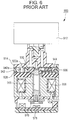
- the rotational input device, indicated at 900, will now be described with reference to Fig. 6 .
- an operation knob 912 is connected to a planetary carrier 914, which rotatably supports a planetary gear 928.
- the planetary gear 928 meshes with an outer toothed portion 930a of a sun gear 930 to which an output shaft 966 is secured, and also meshes with an inner toothed portion 942a of an outer gear 942.
- a plunger 936 provided for the sun gear 930 is in elastic contact with a recess cam portion 944 of the outer gear 942.
- a solenoid unit 958 prevents rotation of the outer gear 942 in accordance with an output of a magnetic sensor 978 facing a magnet 976 attached to the output shaft 966.
- Such a configuration enables reliable detection of a small angle of rotation of a rotatable operation member rotated in an opposite direction beyond its operation range.
- the rotational input device 900 includes the sensor element and the magnetic substance for detection of an angle of rotation (hereinafter, also referred to as a "rotation angle") of the operation knob.
- a rotation detection unit 800 may have a structure as illustrated in Fig. 7 .
- the rotation detection unit 800 includes a sensor element 820 and a magnetic substance 810.
- the sensor element 820 and the magnetic substance 810 are spaced from each other.
- the sensor element 820 is disposed on an insulating substrate (not illustrated).
- the magnetic substance 810 has a flat and wide bottom surface 810a disposed in plane-parallel face-to-face relationship with an upper surface of the sensor element 820.
- the magnetic substance 810 is magnetized in a magnetization direction M0.
- the sensor element 820 includes a sensor element body 820a and a detection mechanism 821 disposed at substantially the center of the sensor element body 820a.
- the detection mechanism 821 can detect a rotation angle of the magnetic substance 810 in response to a rotation of the magnetic substance 810.
- a vector distribution of magnetic field lines H0 appears around the magnetic substance 810 as illustrated in Fig. 8A .
- the magnetic field lines H0 from the north magnetic pole to the south magnetic pole are directed straight in central part, corresponding to the location of the detection mechanism 821, of the magnetic substance 810 along the width of the magnetic substance 810.
- the orientations of the magnetic field lines are more inclined. In other words, a barrel-shaped distortion occurs along the magnetic field lines H0.
- the sensor element 820 may be misaligned relative to the magnetic substance 810. Misalignment results from, for example, an installation error caused at installation of the sensor element 820 on the insulating substrate. If the sensor element 820 is misaligned relative to the magnetic substance 810, a barrel-shaped distortion along the magnetic field lines H0 will cause a rotation angle of the magnetic substance 810 detected by the detection mechanism 821 to include an angle error ⁇ .
- the angle error ⁇ is proportional to the magnitude of misalignment. Disadvantageously, as the misalignment of the sensor element 820 relative to the magnetic substance 810 increases, the angle error ⁇ also increases, as illustrated in Fig. 8B .
- the present invention has been made in view of the above-described circumstances in the art and provides a rotational input device in which if a sensor element is misaligned relative to a magnetic substance, an angle error will be less likely to occur.
- An aspect of the present invention provides a rotational input device including an insulating substrate, a sensor element disposed on the insulating substrate, and a magnetic substance spaced close to the sensor element.
- the sensor element includes a detection mechanism configured to detect orientations of magnetic field lines around the sensor element and has a sensor element parallel surface facing the magnetic substance.
- the magnetic substance has a bottom surface that is located adjacent to the sensor element so as to face the sensor element parallel surface, and includes two ridges that protrude from the bottom surface toward the sensor element and extend parallel to each other.
- the two ridges each have a ridge parallel surface located adjacent to the sensor element such that the ridge parallel surface is substantially parallel to the sensor element parallel surface.
- the ridge parallel surface has a substantially rectangular shape in plan view.
- the magnetic substance is magnetized in a magnetization direction identical to a longitudinal direction of the ridges.
- the rotational input device with such a configuration includes the two ridges extending in the same direction as the magnetization direction of the magnetic substance, distortions of the magnetic field lines emanating from the two ridges cancel one another in a region between the two ridges.
- the magnetic field lines emanating from the entire magnetic substance extend in the magnetization direction of the magnetic substance in this region. Consequently, an angle error is less likely to occur if the sensor element is misaligned relative to the magnetic substance.
- the two ridges are arranged at a distance from each other and the distance is greater than a width of the detection mechanism in a direction orthogonal to the longitudinal direction of the ridges.
- the two ridges may be arranged symmetrically in a direction orthogonal to the longitudinal direction of the ridges.
- the symmetrical arrangement of the two ridges enables distortions of the magnetic field lines emanating from the two ridges to precisely cancel one another if a misalignment of the sensor element relative to the magnetic substance occurs either to the right or to the left of the detection mechanism.
- the rotational input device includes the two ridges extending in the same direction as the magnetization direction of the magnetic substance, the distortions of the magnetic field lines emanating from the two ridges cancel one another in the region between the two ridges.
- the magnetic field lines emanating from the entire magnetic substance extend in the magnetization direction of the magnetic substance in the region. Consequently, if the sensor element is misaligned relative to the magnetic substance, an angle error will be less likely to occur.
- a rotational input device 100 is used as an input operation mechanism for an input operation of an electronic apparatus or a vehicle.
- an input operation can be performed by rotating an operation knob.
- An input depends on a rotation angle of the operation knob relative to a predetermined position, so that different inputs can be achieved.
- Applications of the rotational input device 100 are not limited to those described in the following embodiments, and can be modified as appropriate.
- the term “+X” direction refers to a rightward direction
- the term “-X” direction refers to a leftward direction
- the term “+Y” direction refers to a direction into the plane of the page
- the term “-Y” direction refers to a direction out of the plane of the page
- the term “+Z” direction refers to an upward direction
- the term “-Z” direction refers to a downward direction.
- Fig. 1 is a perspective view of the rotational input device 100.
- Fig. 2 is a perspective view of a rotation detection unit 50 in the rotational input device 100 as viewed from below.
- Fig. 3 is a bottom plan view of the rotation detection unit 50.
- Fig. 4 is a front schematic view illustrating the rotation detection unit 50 and an operation knob 45.
- an insulating substrate 30 is illustrated as being transparent for easy viewing of a sensor element 20.
- the rotational input device 100 includes a substantially rectangular case 40, the operation knob 45 rotatably attached to the case 40, and the rotation detection unit 50 accommodated in the case 40.
- the rotation detection unit 50 detects a rotation angle of the operation knob 45.
- the rotational input device 100 outputs information indicating the rotation angle detected by the rotation detection unit 50 to, for example, the electronic apparatus.
- the rotation detection unit 50 may detect, for example, a rotation direction and a rotation speed in addition to a rotation angle.
- the operation knob 45 includes an operation portion 45a protruding upwardly (in the +Z direction) through an opening of the case 40 and a shaft 45b extending downwardly (in the -Z direction) from the operation portion 45a and coupled to the rotation detection unit 50.
- the rotation detection unit 50 includes the insulating substrate 30, the sensor element 20 disposed on the insulating substrate 30, and a magnetic substance 10 spaced close to the sensor element 20.
- the insulating substrate 30 is attached horizontally in the case 40.
- the insulating substrate 30 includes wiring lines (not illustrated) through which an output signal of the sensor element 20 is transmitted to the outside of the case 40.
- the shaft 45b of the above-described operation knob 45 is disposed perpendicular to the surface of the insulating substrate 30.
- the sensor element 20 includes a sensor element body 20a and a plurality of terminals 20b arranged on the sensor element body 20a.
- the sensor element 20 further includes a detection mechanism 21 disposed in the sensor element body 20a.
- the detection mechanism 21 detects orientations of magnetic field lines around the sensor element 20.
- the sensor element 20 (sensor element body 20a) has a sensor element parallel surface 20c facing the magnetic substance 10.
- the terminals 20b are arranged to output a signal detected by the detection mechanism 21 to, for example, the external electronic apparatus.
- the sensor element body 20a is made of synthetic resin.
- the above-described detection mechanism 21 is embedded in the sensor element body 20a.
- the detection mechanism 21 has a substantially square shape in plan view.
- the detection mechanism 21 is disposed in substantially central part of the sensor element 20.
- the detection mechanism 21 is disposed in the sensor element 20 such that the detection mechanism 21 is parallel to a surface of the insulating substrate 30.
- the detection mechanism 21 has a width W1 in the rightward or leftward direction, or lateral direction.
- the center of the detection mechanism 21 coincides with an extension of the axis of the shaft 45b.
- the magnetic substance 10 is spaced close to the above-described sensor element 20.
- the magnetic substance 10 has a bottom surface 10a located adjacent to the sensor element 20 such that the bottom surface 10a faces the sensor element parallel surface 20c, an upper surface 10b including flat portions opposite the bottom surface 10a, and a plurality of side surfaces 10c including flat portions perpendicular to the bottom surface 10a.
- the magnetic substance 10 has a rectangular shape in plan view and is substantially rectangular-parallelepiped.
- the magnetic substance 10 is magnetized in a magnetization direction M1, that is, in the direction out of the plane of the page of each of Figs. 2 and 4 .
- the magnetic substance 10 is a permanent magnet.
- the magnetic substance 10 further includes two ridges 11 protruding from the bottom surface 10a toward the sensor element 20 and extending parallel to each other.
- the two ridges 11 are arranged parallel to each other such that the ridges are symmetric about the extension of the axis of the shaft 45b.
- the ridges 11 are arranged parallel to each other symmetrically about a rotation axis of the magnetic substance 10 to be rotated in response to a rotation of the operation knob 45.
- the two ridges 11 each have a ridge parallel surface 11a substantially parallel to the sensor element parallel surface 20c of the sensor element 20.
- the ridge parallel surface 11a has a rectangular shape in plan view.
- the ridge parallel surface 11a faces the insulating substrate 30 and the sensor element parallel surface 20c of the sensor element 20.
- the magnetization direction M1 of the magnetic substance 10 is identical to the longitudinal direction of the ridges 11.
- the ridges 11 extend in such a manner that the longitudinal direction of the ridges is orthogonal to the rotation axis of the magnetic substance 10 so that the magnetization direction M1 is orthogonal to the rotation axis of the magnetic substance 10.
- the two ridges 11 define a groove 13 therebetween.
- the groove 13 has a groove parallel surface 13a, which faces the detection mechanism 21 of the sensor element 20.
- the groove 13 has a width providing a predetermined distance L1 in the lateral direction.
- the ridges 11 are spaced the predetermined distance L1 from each other.
- the predetermined distance L1 between the two ridges 11 is set greater than the width W1 of the detection mechanism 21.
- the width W1 of the detection mechanism 21 is within the predetermined distance L1 provided by the groove 13 in the lateral direction.
- the ridge parallel surface 11a of each ridge 11 and the detection mechanism 21 in the sensor element 20 are spaced a predetermined distance D1 from each other.
- the shaft 45b of the above-described operation knob 45 is coupled to the magnetic substance 10.
- the magnetic substance 10 is rotatably held in the case 40 (refer to Fig. 1 ).
- the magnetic substance 10 is rotated in conjunction with the operation knob 45 such that a rotation angle of the magnetic substance 10 depends on an operation angle of the operation knob 45.
- Fig. 5A is a schematic diagram illustrating magnetic field lines H1 in the rotation detection unit 50.
- Fig. 5B is a graph illustrating the angle error ⁇ , indicated by a solid line, plotted against a misalignment of the sensor element 20.
- a broken line indicates the angle error ⁇ in the above-described related-art rotation detection unit 800 for comparison.
- vector distributions of the magnetic field lines H1 appear around the magnetic substance 10.
- the two ridges 11 work like individual magnets.
- the vector distributions of the magnetic field lines H1 correspond to the two ridges 11.
- the magnetic field line H1 on a line connecting the centers of the north and south magnetic poles of each of the two ridges 11 is directed straight.
- the magnetic field lines H1 curve more as indicated by alternate long and short dashed lines in Fig. 5A .
- the magnetic field lines H1 emanating from the right ridge 11 in Fig. 5A would curve to the left in a region between the two ridges 11, namely, in the region corresponding to the groove 13.
- the magnetic field lines H1 emanating from the left ridge 11 would curve to the right in the region corresponding to the groove 13.
- the symmetrical parallel arrangement of the two ridges 11 protruding from the magnetic substance 10 causes the opposing magnetic field lines H1 in the groove 13 to cancel one another, thus changing the distributions of magnetic field lines.
- the magnetic field lines H1 are directed straight at any depth in the groove 13 as indicated by full-line arrows in Fig. 5A .
- the magnetic field lines emanating from the magnetic substance 10 include a layer of widely distributed magnetic field lines H1 parallel to one another in the region between the two ridges 11 in which the orientations of the parallel magnetic field lines H1 are hardly distorted.
- this layer is aligned with the detection mechanism 21.
- an angle error ⁇ included in a rotation angle of the magnetic substance 10 detected by the detection mechanism 21 is less than an angle error ⁇ in the related-art rotation detection unit 800, as illustrated in Fig. 5B.
- Fig. 5B demonstrates that the angle error ⁇ in the embodiment is substantially half that in the related art.
- the predetermined distance L1 between the two ridges 11 and the predetermined distance D1 between the ridge parallel surfaces 11a of the ridges 11 and the detection mechanism 21 in the sensor element 20 are set in consideration of the dimensions of the magnetic substance 10 and the detection mechanism 21 such that the angle error ⁇ is minimized.
- the rotational input device 100 includes the two ridges 11 extending in the same direction as the magnetization direction M1 of the magnetic substance 10, the distortions of the magnetic field lines H1 emanating from the two ridges 11 cancel one another in the region between the two ridges 11.
- the magnetic field lines H1 emanating from the entire magnetic substance 10 extend in the magnetization direction M1 of the magnetic substance 10 in this region. Consequently, if the sensor element 20 is misaligned relative to the magnetic substance 10, an angle error ⁇ will be less likely to occur.
- the symmetrical arrangement of the two ridges 11 enables the distortions of the magnetic field lines H1 emanating from the two ridges 11 to precisely cancel one another if a misalignment of the sensor element 20 relative to the magnetic substance 10 occurs either to the right or to the left of the detection mechanism 21.
- the rotational input device includes the two ridges extending in the same direction as the magnetization direction of the magnetic substance, the distortions of the magnetic field lines emanating from the two ridges cancel one another in the region between the two ridges.
- the magnetic field lines emanating from the entire magnetic substance extend in the magnetization direction of the magnetic substance in this region. Consequently, if the sensor element is misaligned relative to the magnetic substance, an angle error will be less likely to occur.
Landscapes
- Physics & Mathematics (AREA)
- General Physics & Mathematics (AREA)
- Engineering & Computer Science (AREA)
- Automation & Control Theory (AREA)
- Transmission And Conversion Of Sensor Element Output (AREA)
- Mechanical Control Devices (AREA)
- Measurement Of Length, Angles, Or The Like Using Electric Or Magnetic Means (AREA)
Description
- The present invention relates to rotational input devices, and in particular, relates to a rotational input device that detects an angle of rotation by using a magnetic substance and a magnetic sensor.
- Rotational input devices detecting an angle of rotation by using a magnetic substance and a magnetic sensor have been developed for, for example, in-vehicle apparatuses. Such a rotational input device includes an operation knob. An operator can properly operate an in-vehicle apparatus by rotating the operation knob.
- Japanese Unexamined Patent Application Publication No.
2012-079295 Fig. 6 . - In the
rotational input device 900, anoperation knob 912 is connected to aplanetary carrier 914, which rotatably supports aplanetary gear 928. Theplanetary gear 928 meshes with anouter toothed portion 930a of asun gear 930 to which anoutput shaft 966 is secured, and also meshes with aninner toothed portion 942a of anouter gear 942. Aplunger 936 provided for thesun gear 930 is in elastic contact with arecess cam portion 944 of theouter gear 942. Asolenoid unit 958 prevents rotation of theouter gear 942 in accordance with an output of amagnetic sensor 978 facing amagnet 976 attached to theoutput shaft 966. - Such a configuration enables reliable detection of a small angle of rotation of a rotatable operation member rotated in an opposite direction beyond its operation range.
- The
rotational input device 900 includes the sensor element and the magnetic substance for detection of an angle of rotation (hereinafter, also referred to as a "rotation angle") of the operation knob. For arrangement of such a sensor element and such a magnetic substance, arotation detection unit 800 may have a structure as illustrated inFig. 7 . - The
rotation detection unit 800 includes asensor element 820 and amagnetic substance 810. Thesensor element 820 and themagnetic substance 810 are spaced from each other. Thesensor element 820 is disposed on an insulating substrate (not illustrated). Themagnetic substance 810 has a flat andwide bottom surface 810a disposed in plane-parallel face-to-face relationship with an upper surface of thesensor element 820. Themagnetic substance 810 is magnetized in a magnetization direction M0. Thesensor element 820 includes asensor element body 820a and adetection mechanism 821 disposed at substantially the center of thesensor element body 820a. Thedetection mechanism 821 can detect a rotation angle of themagnetic substance 810 in response to a rotation of themagnetic substance 810. - In the structure of the
rotation detection unit 800, a vector distribution of magnetic field lines H0 appears around themagnetic substance 810 as illustrated inFig. 8A . In the vector distribution of the magnetic field lines H0, the magnetic field lines H0 from the north magnetic pole to the south magnetic pole are directed straight in central part, corresponding to the location of thedetection mechanism 821, of themagnetic substance 810 along the width of themagnetic substance 810. As the magnetic field lines H0 are farther away from the central part, the orientations of the magnetic field lines are more inclined. In other words, a barrel-shaped distortion occurs along the magnetic field lines H0. - The
sensor element 820 may be misaligned relative to themagnetic substance 810. Misalignment results from, for example, an installation error caused at installation of thesensor element 820 on the insulating substrate. If thesensor element 820 is misaligned relative to themagnetic substance 810, a barrel-shaped distortion along the magnetic field lines H0 will cause a rotation angle of themagnetic substance 810 detected by thedetection mechanism 821 to include an angle error Δθ. The angle error Δθ is proportional to the magnitude of misalignment. Disadvantageously, as the misalignment of thesensor element 820 relative to themagnetic substance 810 increases, the angle error Δθ also increases, as illustrated inFig. 8B . - The present invention has been made in view of the above-described circumstances in the art and provides a rotational input device in which if a sensor element is misaligned relative to a magnetic substance, an angle error will be less likely to occur.
- An aspect of the present invention provides a rotational input device including an insulating substrate, a sensor element disposed on the insulating substrate, and a magnetic substance spaced close to the sensor element. The sensor element includes a detection mechanism configured to detect orientations of magnetic field lines around the sensor element and has a sensor element parallel surface facing the magnetic substance. The magnetic substance has a bottom surface that is located adjacent to the sensor element so as to face the sensor element parallel surface, and includes two ridges that protrude from the bottom surface toward the sensor element and extend parallel to each other. The two ridges each have a ridge parallel surface located adjacent to the sensor element such that the ridge parallel surface is substantially parallel to the sensor element parallel surface. The ridge parallel surface has a substantially rectangular shape in plan view. The magnetic substance is magnetized in a magnetization direction identical to a longitudinal direction of the ridges.
- Since the rotational input device with such a configuration includes the two ridges extending in the same direction as the magnetization direction of the magnetic substance, distortions of the magnetic field lines emanating from the two ridges cancel one another in a region between the two ridges. Thus, the magnetic field lines emanating from the entire magnetic substance extend in the magnetization direction of the magnetic substance in this region. Consequently, an angle error is less likely to occur if the sensor element is misaligned relative to the magnetic substance.
- In this aspect, preferably, the two ridges are arranged at a distance from each other and the distance is greater than a width of the detection mechanism in a direction orthogonal to the longitudinal direction of the ridges.
- In this configuration, since the distance between the two ridges is set greater than the width of the detection mechanism, a wide region in which the magnetic field lines extend in the magnetization direction of the magnetic substance can be set.
- In this aspect, the two ridges may be arranged symmetrically in a direction orthogonal to the longitudinal direction of the ridges.
- In this configuration, the symmetrical arrangement of the two ridges enables distortions of the magnetic field lines emanating from the two ridges to precisely cancel one another if a misalignment of the sensor element relative to the magnetic substance occurs either to the right or to the left of the detection mechanism.
- Since the rotational input device according to the present invention includes the two ridges extending in the same direction as the magnetization direction of the magnetic substance, the distortions of the magnetic field lines emanating from the two ridges cancel one another in the region between the two ridges. Thus, the magnetic field lines emanating from the entire magnetic substance extend in the magnetization direction of the magnetic substance in the region. Consequently, if the sensor element is misaligned relative to the magnetic substance, an angle error will be less likely to occur.
-
-
Fig. 1 is a perspective view of a rotational input device according to an embodiment of the present invention; -
Fig. 2 is a perspective view of a rotation detection unit in the rotational input device as viewed from below; -
Fig. 3 is a bottom plan view of the rotation detection unit; -
Fig. 4 is a front schematic view illustrating the rotation detection unit and an operation knob; -
Fig. 5A is a schematic diagram illustrating magnetic field lines in the rotation detection unit; -
Fig. 5B is a graph illustrating the relationship between an angle error and a misalignment; -
Fig. 6 is a longitudinal sectional view of a related-art rotational input device; -
Fig. 7 is a perspective view of a rotation detection unit in the related-art rotational input device as viewed from below; -
Fig. 8A is a schematic diagram illustrating magnetic field lines in the rotation detection unit in the related-art rotational input device; and -
Fig. 8B is a graph illustrating the relationship between an angle error and a misalignment. - A rotational input device according to the present invention will be described below with reference to the drawings. A
rotational input device 100 according to an embodiment is used as an input operation mechanism for an input operation of an electronic apparatus or a vehicle. For example, an input operation can be performed by rotating an operation knob. An input depends on a rotation angle of the operation knob relative to a predetermined position, so that different inputs can be achieved. Applications of therotational input device 100 are not limited to those described in the following embodiments, and can be modified as appropriate. As used herein and in the figures, unless otherwise noted, the term "+X" direction refers to a rightward direction, the term "-X" direction refers to a leftward direction, the term "+Y" direction refers to a direction into the plane of the page, the term "-Y" direction refers to a direction out of the plane of the page, the term "+Z" direction refers to an upward direction, and the term "-Z" direction refers to a downward direction. - The structure of the
rotational input device 100 according to the embodiment of the present invention will be described with reference toFigs. 1 to 4 .Fig. 1 is a perspective view of therotational input device 100.Fig. 2 is a perspective view of arotation detection unit 50 in therotational input device 100 as viewed from below.Fig. 3 is a bottom plan view of therotation detection unit 50.Fig. 4 is a front schematic view illustrating therotation detection unit 50 and anoperation knob 45. InFig. 2 , an insulatingsubstrate 30 is illustrated as being transparent for easy viewing of asensor element 20. - As illustrated in
Fig. 1 , therotational input device 100 includes a substantiallyrectangular case 40, theoperation knob 45 rotatably attached to thecase 40, and therotation detection unit 50 accommodated in thecase 40. Therotation detection unit 50 detects a rotation angle of theoperation knob 45. Therotational input device 100 outputs information indicating the rotation angle detected by therotation detection unit 50 to, for example, the electronic apparatus. Therotation detection unit 50 may detect, for example, a rotation direction and a rotation speed in addition to a rotation angle. - The
operation knob 45 includes anoperation portion 45a protruding upwardly (in the +Z direction) through an opening of thecase 40 and ashaft 45b extending downwardly (in the -Z direction) from theoperation portion 45a and coupled to therotation detection unit 50. - As illustrated in
Fig. 2 , therotation detection unit 50 includes the insulatingsubstrate 30, thesensor element 20 disposed on the insulatingsubstrate 30, and amagnetic substance 10 spaced close to thesensor element 20. - The insulating
substrate 30 is attached horizontally in thecase 40. The insulatingsubstrate 30 includes wiring lines (not illustrated) through which an output signal of thesensor element 20 is transmitted to the outside of thecase 40. Theshaft 45b of the above-describedoperation knob 45 is disposed perpendicular to the surface of the insulatingsubstrate 30. - The
sensor element 20 includes asensor element body 20a and a plurality ofterminals 20b arranged on thesensor element body 20a. Thesensor element 20 further includes adetection mechanism 21 disposed in thesensor element body 20a. Thedetection mechanism 21 detects orientations of magnetic field lines around thesensor element 20. The sensor element 20 (sensor element body 20a) has a sensor elementparallel surface 20c facing themagnetic substance 10. Theterminals 20b are arranged to output a signal detected by thedetection mechanism 21 to, for example, the external electronic apparatus. Thesensor element body 20a is made of synthetic resin. The above-describeddetection mechanism 21 is embedded in thesensor element body 20a. - As illustrated in
Fig. 3 , thedetection mechanism 21 has a substantially square shape in plan view. Thedetection mechanism 21 is disposed in substantially central part of thesensor element 20. Furthermore, as illustrated inFig. 4 , thedetection mechanism 21 is disposed in thesensor element 20 such that thedetection mechanism 21 is parallel to a surface of the insulatingsubstrate 30. Thedetection mechanism 21 has a width W1 in the rightward or leftward direction, or lateral direction. The center of thedetection mechanism 21 coincides with an extension of the axis of theshaft 45b. - As illustrated in
Figs. 2 and4 , themagnetic substance 10 is spaced close to the above-describedsensor element 20. Themagnetic substance 10 has abottom surface 10a located adjacent to thesensor element 20 such that thebottom surface 10a faces the sensor elementparallel surface 20c, anupper surface 10b including flat portions opposite thebottom surface 10a, and a plurality ofside surfaces 10c including flat portions perpendicular to thebottom surface 10a. Themagnetic substance 10 has a rectangular shape in plan view and is substantially rectangular-parallelepiped. Themagnetic substance 10 is magnetized in a magnetization direction M1, that is, in the direction out of the plane of the page of each ofFigs. 2 and4 . In the embodiment, themagnetic substance 10 is a permanent magnet. - The
magnetic substance 10 further includes tworidges 11 protruding from thebottom surface 10a toward thesensor element 20 and extending parallel to each other. The tworidges 11 are arranged parallel to each other such that the ridges are symmetric about the extension of the axis of theshaft 45b. In other words, theridges 11 are arranged parallel to each other symmetrically about a rotation axis of themagnetic substance 10 to be rotated in response to a rotation of theoperation knob 45. - The two
ridges 11 each have a ridgeparallel surface 11a substantially parallel to the sensor elementparallel surface 20c of thesensor element 20. The ridgeparallel surface 11a has a rectangular shape in plan view. The ridgeparallel surface 11a faces the insulatingsubstrate 30 and the sensor elementparallel surface 20c of thesensor element 20. In other words, the magnetization direction M1 of themagnetic substance 10 is identical to the longitudinal direction of theridges 11. Theridges 11 extend in such a manner that the longitudinal direction of the ridges is orthogonal to the rotation axis of themagnetic substance 10 so that the magnetization direction M1 is orthogonal to the rotation axis of themagnetic substance 10. The tworidges 11 define agroove 13 therebetween. Thegroove 13 has a grooveparallel surface 13a, which faces thedetection mechanism 21 of thesensor element 20. - As illustrated in
Fig. 4 , thegroove 13 has a width providing a predetermined distance L1 in the lateral direction. In other words, theridges 11 are spaced the predetermined distance L1 from each other. The predetermined distance L1 between the tworidges 11 is set greater than the width W1 of thedetection mechanism 21. In other words, the width W1 of thedetection mechanism 21 is within the predetermined distance L1 provided by thegroove 13 in the lateral direction. Furthermore, the ridgeparallel surface 11a of eachridge 11 and thedetection mechanism 21 in thesensor element 20 are spaced a predetermined distance D1 from each other. - In the
rotation detection unit 50 of therotational input device 100, theshaft 45b of the above-describedoperation knob 45 is coupled to themagnetic substance 10. Themagnetic substance 10 is rotatably held in the case 40 (refer toFig. 1 ). Themagnetic substance 10 is rotated in conjunction with theoperation knob 45 such that a rotation angle of themagnetic substance 10 depends on an operation angle of theoperation knob 45. - An operation of the
rotational input device 100 according to the embodiment of the present invention will now be described with reference toFigs. 5A and 5B. Fig. 5A is a schematic diagram illustrating magnetic field lines H1 in therotation detection unit 50.Fig. 5B is a graph illustrating the angle error Δθ, indicated by a solid line, plotted against a misalignment of thesensor element 20. InFig. 5B , a broken line indicates the angle error Δθ in the above-described related-artrotation detection unit 800 for comparison. - As illustrated in
Fig. 5A , vector distributions of the magnetic field lines H1 appear around themagnetic substance 10. In therotation detection unit 50, the tworidges 11 work like individual magnets. The vector distributions of the magnetic field lines H1 correspond to the tworidges 11. Specifically, the magnetic field line H1 on a line connecting the centers of the north and south magnetic poles of each of the tworidges 11 is directed straight. As the magnetic field lines H1 are farther away from the line connecting the centers, the magnetic field lines H1 curve more as indicated by alternate long and short dashed lines inFig. 5A . - For example, the magnetic field lines H1 emanating from the
right ridge 11 inFig. 5A would curve to the left in a region between the tworidges 11, namely, in the region corresponding to thegroove 13. The magnetic field lines H1 emanating from theleft ridge 11 would curve to the right in the region corresponding to thegroove 13. However, the symmetrical parallel arrangement of the tworidges 11 protruding from themagnetic substance 10 causes the opposing magnetic field lines H1 in thegroove 13 to cancel one another, thus changing the distributions of magnetic field lines. Specifically, the magnetic field lines H1 are directed straight at any depth in thegroove 13 as indicated by full-line arrows inFig. 5A . In other words, the magnetic field lines emanating from themagnetic substance 10 include a layer of widely distributed magnetic field lines H1 parallel to one another in the region between the tworidges 11 in which the orientations of the parallel magnetic field lines H1 are hardly distorted. In the embodiment, this layer is aligned with thedetection mechanism 21. - Consequently, if the
sensor element 20 is misaligned relative to themagnetic substance 10, an angle error Δθ included in a rotation angle of themagnetic substance 10 detected by thedetection mechanism 21 is less than an angle error Δθ in the related-artrotation detection unit 800, as illustrated inFig. 5B. Fig. 5B demonstrates that the angle error Δθ in the embodiment is substantially half that in the related art. - The predetermined distance L1 between the two
ridges 11 and the predetermined distance D1 between the ridgeparallel surfaces 11a of theridges 11 and thedetection mechanism 21 in thesensor element 20 are set in consideration of the dimensions of themagnetic substance 10 and thedetection mechanism 21 such that the angle error Δθ is minimized. - Advantages of the embodiment will now be described.
- Since the
rotational input device 100 includes the tworidges 11 extending in the same direction as the magnetization direction M1 of themagnetic substance 10, the distortions of the magnetic field lines H1 emanating from the tworidges 11 cancel one another in the region between the tworidges 11. Thus, the magnetic field lines H1 emanating from the entiremagnetic substance 10 extend in the magnetization direction M1 of themagnetic substance 10 in this region. Consequently, if thesensor element 20 is misaligned relative to themagnetic substance 10, an angle error Δθ will be less likely to occur. - In addition, since the distance L1 between the two
ridges 11 is set greater than the width W1 of thedetection mechanism 21, a wide region in which the magnetic field lines H1 extend in the magnetization direction M1 of themagnetic substance 10 can be set. - In addition, the symmetrical arrangement of the two
ridges 11 enables the distortions of the magnetic field lines H1 emanating from the tworidges 11 to precisely cancel one another if a misalignment of thesensor element 20 relative to themagnetic substance 10 occurs either to the right or to the left of thedetection mechanism 21. - As described above, since the rotational input device according to the present invention includes the two ridges extending in the same direction as the magnetization direction of the magnetic substance, the distortions of the magnetic field lines emanating from the two ridges cancel one another in the region between the two ridges. Thus, the magnetic field lines emanating from the entire magnetic substance extend in the magnetization direction of the magnetic substance in this region. Consequently, if the sensor element is misaligned relative to the magnetic substance, an angle error will be less likely to occur.
- The present invention is not limited to the above-described embodiments and can be variously modified and practiced without departing from the spirit and scope of the invention.
Claims (3)
- A rotational input device (100) comprising:an insulating substrate (30);a sensor element (20) disposed on the insulating substrate; anda magnetic substance (10) spaced close to the sensor element,the sensor element including a detection mechanism (21) configured to detect orientations of magnetic field lines (HI) around the sensor element and having a sensor element parallel surface (20c) facing the magnetic substance,the magnetic substance having a bottom surface (10a) that is located adjacent to the sensor element so as to face the sensor element parallel surface and including two ridges (11) that protrude from the bottom surface toward the sensor element and extend parallel to each other,the two ridges each having a ridge parallel surface located adjacent to the sensor element such that the ridge parallel surface is substantially parallel to the sensor element parallel surface, the ridge parallel surface having a substantially rectangular shape in plan view,the magnetic substance being magnetized in a magnetization direction (M1) identical to a longitudinal direction of the ridges.
- The device according to Claim 1, wherein the two ridges are arranged at a distance (L1) from each other and the distance is greater than a width (W1) of the detection mechanism in a direction orthogonal to the longitudinal direction of the ridges.
- The device according to Claim 1 or 2, wherein the two ridges are arranged symmetrically in a direction orthogonal to the longitudinal direction of the ridges.
Applications Claiming Priority (1)
| Application Number | Priority Date | Filing Date | Title |
|---|---|---|---|
| JP2016183780A JP6671269B2 (en) | 2016-09-21 | 2016-09-21 | Rotary input device |
Publications (3)
| Publication Number | Publication Date |
|---|---|
| EP3318951A2 true EP3318951A2 (en) | 2018-05-09 |
| EP3318951A3 EP3318951A3 (en) | 2018-06-27 |
| EP3318951B1 EP3318951B1 (en) | 2019-11-06 |
Family
ID=59901403
Family Applications (1)
| Application Number | Title | Priority Date | Filing Date |
|---|---|---|---|
| EP17191449.2A Active EP3318951B1 (en) | 2016-09-21 | 2017-09-15 | Rotational input device |
Country Status (2)
| Country | Link |
|---|---|
| EP (1) | EP3318951B1 (en) |
| JP (1) | JP6671269B2 (en) |
Citations (1)
| Publication number | Priority date | Publication date | Assignee | Title |
|---|---|---|---|---|
| JP2012079295A (en) | 2010-09-07 | 2012-04-19 | Alps Electric Co Ltd | Rotary input device |
Family Cites Families (6)
| Publication number | Priority date | Publication date | Assignee | Title |
|---|---|---|---|---|
| JP3491596B2 (en) * | 1999-06-28 | 2004-01-26 | 株式会社デンソー | Rotation angle detector |
| JP2005048671A (en) * | 2003-07-29 | 2005-02-24 | Mitsubishi Electric Corp | Engine intake control system |
| JP2006208048A (en) * | 2005-01-25 | 2006-08-10 | Denso Corp | Rotation angle detector |
| JP5141780B2 (en) * | 2011-01-12 | 2013-02-13 | Tdk株式会社 | Rotation angle sensor |
| JP6226425B2 (en) * | 2014-01-31 | 2017-11-08 | アルプス電気株式会社 | Rotation input device |
| JP2016099190A (en) * | 2014-11-20 | 2016-05-30 | アイシン精機株式会社 | Rotation angle detector |
-
2016
- 2016-09-21 JP JP2016183780A patent/JP6671269B2/en active Active
-
2017
- 2017-09-15 EP EP17191449.2A patent/EP3318951B1/en active Active
Patent Citations (1)
| Publication number | Priority date | Publication date | Assignee | Title |
|---|---|---|---|---|
| JP2012079295A (en) | 2010-09-07 | 2012-04-19 | Alps Electric Co Ltd | Rotary input device |
Also Published As
| Publication number | Publication date |
|---|---|
| EP3318951A3 (en) | 2018-06-27 |
| JP2018049418A (en) | 2018-03-29 |
| EP3318951B1 (en) | 2019-11-06 |
| JP6671269B2 (en) | 2020-03-25 |
Similar Documents
| Publication | Publication Date | Title |
|---|---|---|
| US20240217125A1 (en) | Magnetic lock with throwable robot | |
| EP0842392B1 (en) | Gear tooth sensor with improved resolution and stability | |
| EP2677280B1 (en) | Rotation angle detection device | |
| JP6632333B2 (en) | Rotation angle detection device and angle sensor unit used therefor | |
| CN113324564B (en) | Position detection device, position detection system using same, and steering system | |
| US20160209241A1 (en) | Encoder scale, encoder, drive apparatus, and stage apparatus | |
| KR20020015275A (en) | Sensor for the detection of the direction of a magnetic field | |
| US20180275217A1 (en) | Magnetic sensor | |
| EP2711728A1 (en) | Magnetic sensor device | |
| JP2000028312A (en) | Low profile non-contacting position sensor | |
| CN214011701U (en) | Camera module and electronic device including the same | |
| JPH0979865A (en) | Magnetic detection sensor | |
| CN109073716B (en) | Magnetic sensor device | |
| US7411521B2 (en) | Control system | |
| EP3318951B1 (en) | Rotational input device | |
| US20150022189A1 (en) | Position detection device | |
| JP2022069261A (en) | Magnetic sensor assembly and camera module including the same | |
| US20110036182A1 (en) | Rotary torque detecting device | |
| JPH11153404A (en) | Rotation angle sensor | |
| CN114174769B (en) | Rotation Angle Detection Sensor | |
| US10215588B2 (en) | Position detecting device and structure for using position detecting device | |
| US10107646B2 (en) | Orientation sensor | |
| JP2009085913A (en) | Position detector | |
| US11525747B2 (en) | Sensing device that prevents magnetic field interference | |
| JPH07294540A (en) | Magnetism detection device |
Legal Events
| Date | Code | Title | Description |
|---|---|---|---|
| PUAI | Public reference made under article 153(3) epc to a published international application that has entered the european phase |
Free format text: ORIGINAL CODE: 0009012 |
|
| STAA | Information on the status of an ep patent application or granted ep patent |
Free format text: STATUS: THE APPLICATION HAS BEEN PUBLISHED |
|
| AK | Designated contracting states |
Kind code of ref document: A2 Designated state(s): AL AT BE BG CH CY CZ DE DK EE ES FI FR GB GR HR HU IE IS IT LI LT LU LV MC MK MT NL NO PL PT RO RS SE SI SK SM TR |
|
| AX | Request for extension of the european patent |
Extension state: BA ME |
|
| PUAL | Search report despatched |
Free format text: ORIGINAL CODE: 0009013 |
|
| AK | Designated contracting states |
Kind code of ref document: A3 Designated state(s): AL AT BE BG CH CY CZ DE DK EE ES FI FR GB GR HR HU IE IS IT LI LT LU LV MC MK MT NL NO PL PT RO RS SE SI SK SM TR |
|
| AX | Request for extension of the european patent |
Extension state: BA ME |
|
| RIC1 | Information provided on ipc code assigned before grant |
Ipc: G01B 7/30 20060101ALI20180518BHEP Ipc: G05G 1/08 20060101AFI20180518BHEP |
|
| STAA | Information on the status of an ep patent application or granted ep patent |
Free format text: STATUS: REQUEST FOR EXAMINATION WAS MADE |
|
| 17P | Request for examination filed |
Effective date: 20181130 |
|
| RBV | Designated contracting states (corrected) |
Designated state(s): AL AT BE BG CH CY CZ DE DK EE ES FI FR GB GR HR HU IE IS IT LI LT LU LV MC MK MT NL NO PL PT RO RS SE SI SK SM TR |
|
| RAP1 | Party data changed (applicant data changed or rights of an application transferred) |
Owner name: ALPS ALPINE CO., LTD. |
|
| REG | Reference to a national code |
Ref country code: DE Ref legal event code: R079 Ref document number: 602017008399 Country of ref document: DE Free format text: PREVIOUS MAIN CLASS: G05G0001080000 Ipc: G01D0005140000 |
|
| GRAP | Despatch of communication of intention to grant a patent |
Free format text: ORIGINAL CODE: EPIDOSNIGR1 |
|
| STAA | Information on the status of an ep patent application or granted ep patent |
Free format text: STATUS: GRANT OF PATENT IS INTENDED |
|
| RIC1 | Information provided on ipc code assigned before grant |
Ipc: G01D 5/14 20060101AFI20190408BHEP Ipc: G05G 1/08 20060101ALI20190408BHEP |
|
| INTG | Intention to grant announced |
Effective date: 20190509 |
|
| GRAS | Grant fee paid |
Free format text: ORIGINAL CODE: EPIDOSNIGR3 |
|
| GRAA | (expected) grant |
Free format text: ORIGINAL CODE: 0009210 |
|
| STAA | Information on the status of an ep patent application or granted ep patent |
Free format text: STATUS: THE PATENT HAS BEEN GRANTED |
|
| AK | Designated contracting states |
Kind code of ref document: B1 Designated state(s): AL AT BE BG CH CY CZ DE DK EE ES FI FR GB GR HR HU IE IS IT LI LT LU LV MC MK MT NL NO PL PT RO RS SE SI SK SM TR |
|
| REG | Reference to a national code |
Ref country code: GB Ref legal event code: FG4D |
|
| REG | Reference to a national code |
Ref country code: CH Ref legal event code: EP Ref country code: AT Ref legal event code: REF Ref document number: 1199357 Country of ref document: AT Kind code of ref document: T Effective date: 20191115 |
|
| REG | Reference to a national code |
Ref country code: IE Ref legal event code: FG4D |
|
| REG | Reference to a national code |
Ref country code: DE Ref legal event code: R096 Ref document number: 602017008399 Country of ref document: DE |
|
| REG | Reference to a national code |
Ref country code: NL Ref legal event code: MP Effective date: 20191106 |
|
| REG | Reference to a national code |
Ref country code: LT Ref legal event code: MG4D |
|
| PG25 | Lapsed in a contracting state [announced via postgrant information from national office to epo] |
Ref country code: FI Free format text: LAPSE BECAUSE OF FAILURE TO SUBMIT A TRANSLATION OF THE DESCRIPTION OR TO PAY THE FEE WITHIN THE PRESCRIBED TIME-LIMIT Effective date: 20191106 Ref country code: BG Free format text: LAPSE BECAUSE OF FAILURE TO SUBMIT A TRANSLATION OF THE DESCRIPTION OR TO PAY THE FEE WITHIN THE PRESCRIBED TIME-LIMIT Effective date: 20200206 Ref country code: NO Free format text: LAPSE BECAUSE OF FAILURE TO SUBMIT A TRANSLATION OF THE DESCRIPTION OR TO PAY THE FEE WITHIN THE PRESCRIBED TIME-LIMIT Effective date: 20200206 Ref country code: GR Free format text: LAPSE BECAUSE OF FAILURE TO SUBMIT A TRANSLATION OF THE DESCRIPTION OR TO PAY THE FEE WITHIN THE PRESCRIBED TIME-LIMIT Effective date: 20200207 Ref country code: PT Free format text: LAPSE BECAUSE OF FAILURE TO SUBMIT A TRANSLATION OF THE DESCRIPTION OR TO PAY THE FEE WITHIN THE PRESCRIBED TIME-LIMIT Effective date: 20200306 Ref country code: LT Free format text: LAPSE BECAUSE OF FAILURE TO SUBMIT A TRANSLATION OF THE DESCRIPTION OR TO PAY THE FEE WITHIN THE PRESCRIBED TIME-LIMIT Effective date: 20191106 Ref country code: PL Free format text: LAPSE BECAUSE OF FAILURE TO SUBMIT A TRANSLATION OF THE DESCRIPTION OR TO PAY THE FEE WITHIN THE PRESCRIBED TIME-LIMIT Effective date: 20191106 Ref country code: LV Free format text: LAPSE BECAUSE OF FAILURE TO SUBMIT A TRANSLATION OF THE DESCRIPTION OR TO PAY THE FEE WITHIN THE PRESCRIBED TIME-LIMIT Effective date: 20191106 Ref country code: SE Free format text: LAPSE BECAUSE OF FAILURE TO SUBMIT A TRANSLATION OF THE DESCRIPTION OR TO PAY THE FEE WITHIN THE PRESCRIBED TIME-LIMIT Effective date: 20191106 Ref country code: NL Free format text: LAPSE BECAUSE OF FAILURE TO SUBMIT A TRANSLATION OF THE DESCRIPTION OR TO PAY THE FEE WITHIN THE PRESCRIBED TIME-LIMIT Effective date: 20191106 |
|
| PG25 | Lapsed in a contracting state [announced via postgrant information from national office to epo] |
Ref country code: HR Free format text: LAPSE BECAUSE OF FAILURE TO SUBMIT A TRANSLATION OF THE DESCRIPTION OR TO PAY THE FEE WITHIN THE PRESCRIBED TIME-LIMIT Effective date: 20191106 Ref country code: RS Free format text: LAPSE BECAUSE OF FAILURE TO SUBMIT A TRANSLATION OF THE DESCRIPTION OR TO PAY THE FEE WITHIN THE PRESCRIBED TIME-LIMIT Effective date: 20191106 Ref country code: IS Free format text: LAPSE BECAUSE OF FAILURE TO SUBMIT A TRANSLATION OF THE DESCRIPTION OR TO PAY THE FEE WITHIN THE PRESCRIBED TIME-LIMIT Effective date: 20200306 |
|
| PG25 | Lapsed in a contracting state [announced via postgrant information from national office to epo] |
Ref country code: AL Free format text: LAPSE BECAUSE OF FAILURE TO SUBMIT A TRANSLATION OF THE DESCRIPTION OR TO PAY THE FEE WITHIN THE PRESCRIBED TIME-LIMIT Effective date: 20191106 |
|
| PG25 | Lapsed in a contracting state [announced via postgrant information from national office to epo] |
Ref country code: DK Free format text: LAPSE BECAUSE OF FAILURE TO SUBMIT A TRANSLATION OF THE DESCRIPTION OR TO PAY THE FEE WITHIN THE PRESCRIBED TIME-LIMIT Effective date: 20191106 Ref country code: EE Free format text: LAPSE BECAUSE OF FAILURE TO SUBMIT A TRANSLATION OF THE DESCRIPTION OR TO PAY THE FEE WITHIN THE PRESCRIBED TIME-LIMIT Effective date: 20191106 Ref country code: RO Free format text: LAPSE BECAUSE OF FAILURE TO SUBMIT A TRANSLATION OF THE DESCRIPTION OR TO PAY THE FEE WITHIN THE PRESCRIBED TIME-LIMIT Effective date: 20191106 Ref country code: CZ Free format text: LAPSE BECAUSE OF FAILURE TO SUBMIT A TRANSLATION OF THE DESCRIPTION OR TO PAY THE FEE WITHIN THE PRESCRIBED TIME-LIMIT Effective date: 20191106 Ref country code: ES Free format text: LAPSE BECAUSE OF FAILURE TO SUBMIT A TRANSLATION OF THE DESCRIPTION OR TO PAY THE FEE WITHIN THE PRESCRIBED TIME-LIMIT Effective date: 20191106 |
|
| REG | Reference to a national code |
Ref country code: DE Ref legal event code: R097 Ref document number: 602017008399 Country of ref document: DE |
|
| REG | Reference to a national code |
Ref country code: AT Ref legal event code: MK05 Ref document number: 1199357 Country of ref document: AT Kind code of ref document: T Effective date: 20191106 |
|
| PG25 | Lapsed in a contracting state [announced via postgrant information from national office to epo] |
Ref country code: SM Free format text: LAPSE BECAUSE OF FAILURE TO SUBMIT A TRANSLATION OF THE DESCRIPTION OR TO PAY THE FEE WITHIN THE PRESCRIBED TIME-LIMIT Effective date: 20191106 Ref country code: SK Free format text: LAPSE BECAUSE OF FAILURE TO SUBMIT A TRANSLATION OF THE DESCRIPTION OR TO PAY THE FEE WITHIN THE PRESCRIBED TIME-LIMIT Effective date: 20191106 |
|
| PLBE | No opposition filed within time limit |
Free format text: ORIGINAL CODE: 0009261 |
|
| STAA | Information on the status of an ep patent application or granted ep patent |
Free format text: STATUS: NO OPPOSITION FILED WITHIN TIME LIMIT |
|
| 26N | No opposition filed |
Effective date: 20200807 |
|
| PG25 | Lapsed in a contracting state [announced via postgrant information from national office to epo] |
Ref country code: AT Free format text: LAPSE BECAUSE OF FAILURE TO SUBMIT A TRANSLATION OF THE DESCRIPTION OR TO PAY THE FEE WITHIN THE PRESCRIBED TIME-LIMIT Effective date: 20191106 Ref country code: SI Free format text: LAPSE BECAUSE OF FAILURE TO SUBMIT A TRANSLATION OF THE DESCRIPTION OR TO PAY THE FEE WITHIN THE PRESCRIBED TIME-LIMIT Effective date: 20191106 |
|
| PG25 | Lapsed in a contracting state [announced via postgrant information from national office to epo] |
Ref country code: IT Free format text: LAPSE BECAUSE OF FAILURE TO SUBMIT A TRANSLATION OF THE DESCRIPTION OR TO PAY THE FEE WITHIN THE PRESCRIBED TIME-LIMIT Effective date: 20191106 |
|
| REG | Reference to a national code |
Ref country code: CH Ref legal event code: PL |
|
| REG | Reference to a national code |
Ref country code: BE Ref legal event code: MM Effective date: 20200930 |
|
| PG25 | Lapsed in a contracting state [announced via postgrant information from national office to epo] |
Ref country code: LU Free format text: LAPSE BECAUSE OF NON-PAYMENT OF DUE FEES Effective date: 20200915 |
|
| PG25 | Lapsed in a contracting state [announced via postgrant information from national office to epo] |
Ref country code: FR Free format text: LAPSE BECAUSE OF NON-PAYMENT OF DUE FEES Effective date: 20200930 |
|
| PG25 | Lapsed in a contracting state [announced via postgrant information from national office to epo] |
Ref country code: BE Free format text: LAPSE BECAUSE OF NON-PAYMENT OF DUE FEES Effective date: 20200930 Ref country code: CH Free format text: LAPSE BECAUSE OF NON-PAYMENT OF DUE FEES Effective date: 20200930 Ref country code: IE Free format text: LAPSE BECAUSE OF NON-PAYMENT OF DUE FEES Effective date: 20200915 Ref country code: LI Free format text: LAPSE BECAUSE OF NON-PAYMENT OF DUE FEES Effective date: 20200930 |
|
| GBPC | Gb: european patent ceased through non-payment of renewal fee |
Effective date: 20210915 |
|
| PG25 | Lapsed in a contracting state [announced via postgrant information from national office to epo] |
Ref country code: TR Free format text: LAPSE BECAUSE OF FAILURE TO SUBMIT A TRANSLATION OF THE DESCRIPTION OR TO PAY THE FEE WITHIN THE PRESCRIBED TIME-LIMIT Effective date: 20191106 Ref country code: MT Free format text: LAPSE BECAUSE OF FAILURE TO SUBMIT A TRANSLATION OF THE DESCRIPTION OR TO PAY THE FEE WITHIN THE PRESCRIBED TIME-LIMIT Effective date: 20191106 Ref country code: CY Free format text: LAPSE BECAUSE OF FAILURE TO SUBMIT A TRANSLATION OF THE DESCRIPTION OR TO PAY THE FEE WITHIN THE PRESCRIBED TIME-LIMIT Effective date: 20191106 |
|
| PG25 | Lapsed in a contracting state [announced via postgrant information from national office to epo] |
Ref country code: MK Free format text: LAPSE BECAUSE OF FAILURE TO SUBMIT A TRANSLATION OF THE DESCRIPTION OR TO PAY THE FEE WITHIN THE PRESCRIBED TIME-LIMIT Effective date: 20191106 Ref country code: MC Free format text: LAPSE BECAUSE OF FAILURE TO SUBMIT A TRANSLATION OF THE DESCRIPTION OR TO PAY THE FEE WITHIN THE PRESCRIBED TIME-LIMIT Effective date: 20191106 |
|
| PG25 | Lapsed in a contracting state [announced via postgrant information from national office to epo] |
Ref country code: GB Free format text: LAPSE BECAUSE OF NON-PAYMENT OF DUE FEES Effective date: 20210915 |
|
| PGFP | Annual fee paid to national office [announced via postgrant information from national office to epo] |
Ref country code: DE Payment date: 20250919 Year of fee payment: 9 |