EP3318906B1 - Wavelength selection switching, reconfigurable optical add-drop multiplexer and wavelength selection method - Google Patents
Wavelength selection switching, reconfigurable optical add-drop multiplexer and wavelength selection method Download PDFInfo
- Publication number
- EP3318906B1 EP3318906B1 EP15897936.9A EP15897936A EP3318906B1 EP 3318906 B1 EP3318906 B1 EP 3318906B1 EP 15897936 A EP15897936 A EP 15897936A EP 3318906 B1 EP3318906 B1 EP 3318906B1
- Authority
- EP
- European Patent Office
- Prior art keywords
- optical
- switching engine
- plane
- optical switching
- sub
- Prior art date
- Legal status (The legal status is an assumption and is not a legal conclusion. Google has not performed a legal analysis and makes no representation as to the accuracy of the status listed.)
- Active
Links
- 230000003287 optical effect Effects 0.000 title claims description 367
- 238000010187 selection method Methods 0.000 title claims description 7
- 239000006185 dispersion Substances 0.000 claims description 93
- 239000013307 optical fiber Substances 0.000 claims description 78
- 230000010287 polarization Effects 0.000 claims description 46
- 238000000034 method Methods 0.000 claims description 8
- 230000009471 action Effects 0.000 claims description 5
- 238000010586 diagram Methods 0.000 description 25
- 230000006870 function Effects 0.000 description 11
- 230000000694 effects Effects 0.000 description 5
- 238000004364 calculation method Methods 0.000 description 3
- 238000004590 computer program Methods 0.000 description 3
- 239000004973 liquid crystal related substance Substances 0.000 description 3
- 230000008569 process Effects 0.000 description 3
- 230000002457 bidirectional effect Effects 0.000 description 2
- 238000011161 development Methods 0.000 description 2
- 239000000835 fiber Substances 0.000 description 2
- 238000012545 processing Methods 0.000 description 2
- 229910052710 silicon Inorganic materials 0.000 description 2
- 239000010703 silicon Substances 0.000 description 2
- 230000005540 biological transmission Effects 0.000 description 1
- 238000004422 calculation algorithm Methods 0.000 description 1
- 238000004891 communication Methods 0.000 description 1
- 230000001419 dependent effect Effects 0.000 description 1
- 238000013461 design Methods 0.000 description 1
- 238000005516 engineering process Methods 0.000 description 1
- 238000003384 imaging method Methods 0.000 description 1
- 238000012986 modification Methods 0.000 description 1
- 230000004048 modification Effects 0.000 description 1
Images


Classifications
-
- G—PHYSICS
- G02—OPTICS
- G02B—OPTICAL ELEMENTS, SYSTEMS OR APPARATUS
- G02B6/00—Light guides; Structural details of arrangements comprising light guides and other optical elements, e.g. couplings
- G02B6/24—Coupling light guides
- G02B6/26—Optical coupling means
- G02B6/35—Optical coupling means having switching means
- G02B6/354—Switching arrangements, i.e. number of input/output ports and interconnection types
- G02B6/3544—2D constellations, i.e. with switching elements and switched beams located in a plane
- G02B6/3546—NxM switch, i.e. a regular array of switches elements of matrix type constellation
-
- G—PHYSICS
- G02—OPTICS
- G02B—OPTICAL ELEMENTS, SYSTEMS OR APPARATUS
- G02B6/00—Light guides; Structural details of arrangements comprising light guides and other optical elements, e.g. couplings
- G02B6/24—Coupling light guides
- G02B6/26—Optical coupling means
- G02B6/27—Optical coupling means with polarisation selective and adjusting means
- G02B6/2753—Optical coupling means with polarisation selective and adjusting means characterised by their function or use, i.e. of the complete device
- G02B6/2773—Polarisation splitting or combining
-
- G—PHYSICS
- G02—OPTICS
- G02B—OPTICAL ELEMENTS, SYSTEMS OR APPARATUS
- G02B6/00—Light guides; Structural details of arrangements comprising light guides and other optical elements, e.g. couplings
- G02B6/24—Coupling light guides
- G02B6/26—Optical coupling means
- G02B6/28—Optical coupling means having data bus means, i.e. plural waveguides interconnected and providing an inherently bidirectional system by mixing and splitting signals
- G02B6/293—Optical coupling means having data bus means, i.e. plural waveguides interconnected and providing an inherently bidirectional system by mixing and splitting signals with wavelength selective means
- G02B6/29371—Optical coupling means having data bus means, i.e. plural waveguides interconnected and providing an inherently bidirectional system by mixing and splitting signals with wavelength selective means operating principle based on material dispersion
-
- G—PHYSICS
- G02—OPTICS
- G02B—OPTICAL ELEMENTS, SYSTEMS OR APPARATUS
- G02B6/00—Light guides; Structural details of arrangements comprising light guides and other optical elements, e.g. couplings
- G02B6/24—Coupling light guides
- G02B6/26—Optical coupling means
- G02B6/28—Optical coupling means having data bus means, i.e. plural waveguides interconnected and providing an inherently bidirectional system by mixing and splitting signals
- G02B6/293—Optical coupling means having data bus means, i.e. plural waveguides interconnected and providing an inherently bidirectional system by mixing and splitting signals with wavelength selective means
- G02B6/29379—Optical coupling means having data bus means, i.e. plural waveguides interconnected and providing an inherently bidirectional system by mixing and splitting signals with wavelength selective means characterised by the function or use of the complete device
- G02B6/2938—Optical coupling means having data bus means, i.e. plural waveguides interconnected and providing an inherently bidirectional system by mixing and splitting signals with wavelength selective means characterised by the function or use of the complete device for multiplexing or demultiplexing, i.e. combining or separating wavelengths, e.g. 1xN, NxM
-
- G—PHYSICS
- G02—OPTICS
- G02B—OPTICAL ELEMENTS, SYSTEMS OR APPARATUS
- G02B6/00—Light guides; Structural details of arrangements comprising light guides and other optical elements, e.g. couplings
- G02B6/24—Coupling light guides
- G02B6/26—Optical coupling means
- G02B6/32—Optical coupling means having lens focusing means positioned between opposed fibre ends
-
- G—PHYSICS
- G02—OPTICS
- G02B—OPTICAL ELEMENTS, SYSTEMS OR APPARATUS
- G02B6/00—Light guides; Structural details of arrangements comprising light guides and other optical elements, e.g. couplings
- G02B6/24—Coupling light guides
- G02B6/26—Optical coupling means
- G02B6/35—Optical coupling means having switching means
- G02B6/351—Optical coupling means having switching means involving stationary waveguides with moving interposed optical elements
- G02B6/3524—Optical coupling means having switching means involving stationary waveguides with moving interposed optical elements the optical element being refractive
-
- G—PHYSICS
- G02—OPTICS
- G02B—OPTICAL ELEMENTS, SYSTEMS OR APPARATUS
- G02B6/00—Light guides; Structural details of arrangements comprising light guides and other optical elements, e.g. couplings
- G02B6/24—Coupling light guides
- G02B6/26—Optical coupling means
- G02B6/35—Optical coupling means having switching means
- G02B6/354—Switching arrangements, i.e. number of input/output ports and interconnection types
- G02B6/356—Switching arrangements, i.e. number of input/output ports and interconnection types in an optical cross-connect device, e.g. routing and switching aspects of interconnecting different paths propagating different wavelengths to (re)configure the various input and output links
-
- G—PHYSICS
- G02—OPTICS
- G02B—OPTICAL ELEMENTS, SYSTEMS OR APPARATUS
- G02B6/00—Light guides; Structural details of arrangements comprising light guides and other optical elements, e.g. couplings
- G02B6/24—Coupling light guides
- G02B6/26—Optical coupling means
- G02B6/35—Optical coupling means having switching means
- G02B6/3594—Characterised by additional functional means, e.g. means for variably attenuating or branching or means for switching differently polarized beams
-
- H—ELECTRICITY
- H04—ELECTRIC COMMUNICATION TECHNIQUE
- H04J—MULTIPLEX COMMUNICATION
- H04J14/00—Optical multiplex systems
- H04J14/02—Wavelength-division multiplex systems
- H04J14/0201—Add-and-drop multiplexing
- H04J14/0202—Arrangements therefor
- H04J14/021—Reconfigurable arrangements, e.g. reconfigurable optical add/drop multiplexers [ROADM] or tunable optical add/drop multiplexers [TOADM]
- H04J14/0212—Reconfigurable arrangements, e.g. reconfigurable optical add/drop multiplexers [ROADM] or tunable optical add/drop multiplexers [TOADM] using optical switches or wavelength selective switches [WSS]
-
- H—ELECTRICITY
- H04—ELECTRIC COMMUNICATION TECHNIQUE
- H04Q—SELECTING
- H04Q11/00—Selecting arrangements for multiplex systems
- H04Q11/0001—Selecting arrangements for multiplex systems using optical switching
- H04Q11/0005—Switch and router aspects
-
- G—PHYSICS
- G02—OPTICS
- G02B—OPTICAL ELEMENTS, SYSTEMS OR APPARATUS
- G02B6/00—Light guides; Structural details of arrangements comprising light guides and other optical elements, e.g. couplings
- G02B6/24—Coupling light guides
- G02B6/26—Optical coupling means
- G02B6/35—Optical coupling means having switching means
- G02B6/351—Optical coupling means having switching means involving stationary waveguides with moving interposed optical elements
- G02B6/3512—Optical coupling means having switching means involving stationary waveguides with moving interposed optical elements the optical element being reflective, e.g. mirror
-
- H—ELECTRICITY
- H04—ELECTRIC COMMUNICATION TECHNIQUE
- H04Q—SELECTING
- H04Q11/00—Selecting arrangements for multiplex systems
- H04Q11/0001—Selecting arrangements for multiplex systems using optical switching
- H04Q11/0005—Switch and router aspects
- H04Q2011/0007—Construction
- H04Q2011/0016—Construction using wavelength multiplexing or demultiplexing
-
- H—ELECTRICITY
- H04—ELECTRIC COMMUNICATION TECHNIQUE
- H04Q—SELECTING
- H04Q11/00—Selecting arrangements for multiplex systems
- H04Q11/0001—Selecting arrangements for multiplex systems using optical switching
- H04Q11/0005—Switch and router aspects
- H04Q2011/0007—Construction
- H04Q2011/0026—Construction using free space propagation (e.g. lenses, mirrors)
-
- H—ELECTRICITY
- H04—ELECTRIC COMMUNICATION TECHNIQUE
- H04Q—SELECTING
- H04Q11/00—Selecting arrangements for multiplex systems
- H04Q11/0001—Selecting arrangements for multiplex systems using optical switching
- H04Q11/0005—Switch and router aspects
- H04Q2011/0007—Construction
- H04Q2011/0035—Construction using miscellaneous components, e.g. circulator, polarisation, acousto/thermo optical
-
- H—ELECTRICITY
- H04—ELECTRIC COMMUNICATION TECHNIQUE
- H04Q—SELECTING
- H04Q11/00—Selecting arrangements for multiplex systems
- H04Q11/0001—Selecting arrangements for multiplex systems using optical switching
- H04Q11/0005—Switch and router aspects
- H04Q2011/0037—Operation
- H04Q2011/0039—Electrical control
Definitions
- the present invention relates to the communications field, and in particular, to a wavelength selective switch, a reconfigurable optical add/drop multiplexer, and a wavelength selection method.
- ROADM Reconfigurable Optical Add-Drop Multiplexer, reconfigurable optical add/drop multiplexer
- a colorless (colorless), directionless (directionless), and contentionless (contentionless) ROADM (CDC ROADM for short) is a development direction of a future ROADM architecture.
- Colorless means that any port can be used for outputting any wavelength
- directionless means that any wavelength can be scheduled to any direction
- contentionless means that there is no wavelength conflict when a same wavelength needs to be locally added and dropped simultaneously in multiple directions.
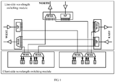
- an ROADM architecture includes a line-side wavelength switching module and a client-side wavelength switching module.
- the line-side wavelength switching module is connected to the client-side wavelength switching module by using an optical fiber.
- the line-side wavelength switching module may include multiple WSSs (Wavelength Selective Switch, wavelength selective switch) and SPs (Splitter, splitter).
- WSSs Wavelength Selective Switch, wavelength selective switch
- SPs Splitter, splitter.
- One WSS and one SP constitute a wavelength switching sub-module in one direction.
- FIG. 1 shows wavelength switching sub-modules in three directions, including an east (east) dimension, a west (west) dimension, and a north (north) dimension.
- the client-side wavelength switching module includes an add module and a drop module.
- the add module includes multiple TX transmitters and one WSS, and the drop module includes multiple RX receivers and one WSS.
- the east dimension is used as an example.
- the optical signal is first broadcast to other several dimensions and the client-side drop module by using an SP.
- the client-side drop module selects and receives the wavelength.
- the WSS in the west dimension selects the wavelength and transfers the wavelength, and blocks wavelengths that are from other dimensions.
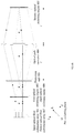
- FIG. 2a is a schematic diagram of a top view of an optical path structure of an N ⁇ M WSS in the prior art.
- FIG. 2b is a schematic diagram of a side view of an optical path structure of an N ⁇ M WSS in the prior art.
- a WDM signal is input from an input port 201 (an input optical fiber), is collimated by a collimator array 202, and is demultiplexed into K sub-wavelength signals by a first-stage grating 203.
- the K sub-wavelength signals are incident to a first-stage optical switching array 206 after passing through a cylindrical lens array 204 and a lens 205.
- the first-stage optical switching array 206 has N rows, and there are K optical switch units in each row. Each optical switch unit deflects one sub-wavelength signal, so that the sub-wavelength signal is incident to a corresponding optical switch unit in a second-stage optical switching array 207.
- the second-stage optical switching array 207 has M rows, and there are K optical switch units in each row. Each optical switch unit is corresponding to one sub-wavelength signal. The optical switch unit corrects an angle of the sub-wavelength signal, so that the sub-wavelength signal is parallel to a direction of an optical axis (Z) in a Y direction.
- All sub-wavelength signals are incident to a second-stage grating 210 after passing through a lens 208 and a cylindrical lens array 209, output to a collimator array 207 after being multiplexed by the second-stage grating 210, and finally output from an output port 208 (an output optical fiber).
- the first-stage optical switching array 206 and the second-stage optical switching array 207 perform optical switching only on a Y plane, and each optical switch unit implements a wavelength selection function by performing deflection in one dimension.
- the first-stage grating 203 and the first-stage optical switching array 206 implement a "beam demultiplexing" function, and switch the sub-wavelength signals from the same input port to different optical switch units in the second-stage optical switching array 207.
- the second-stage optical switching array 207 and the second-stage grating 210 implement a "beam multiplexing" function.
- the second-stage optical switching array in the prior art requires M ⁇ K switch switching units.
- the K switch units occupy spatial positions in an X direction, and K is a relatively large integer.
- optical switching cannot be implemented in two dimensions. Therefore, output ports are restricted in one dimension and cannot be arranged in two dimensions, each output port is corresponding to the K optical switch units, and a quantity of the output ports is restricted.
- WO 2015/008403 A1 discloses an optical path control device, the optical path control device has a light input section 1, an anamorphic converter 2, a dispersive element 5, an optical power element 6, optical deflectors 7 a and 7 b, and a light output section 13.
- a light input section 1 wavelength-multiplexed beams L1 a, L1 b are input from the outside of the optical path control device 100.
- Each of the wavelength-multiplexed beams L1 a, L1 b travels through the anamorphic converter 2, dispersive element 5, and optical power element 6 in this order, is then deflected by either of the optical deflectors 7 a and 7 b, and travels through the optical power element 6, dispersive element 5, and anamorphic converter 2 in this order to be output from the light output section 13.
- US 2012/237218 A1 discloses optical switches including collimator elements that accommodate two or more optical ports.
- the collimator element of D2 include a lens.
- Inbound multi-channel optical signals are guided to the lens by different optical paths configured such that the lens deflects the optical signals at angles that are determined by the optical paths, the optical paths are implemented using optical fibers or optical waveguides.
- embodiments of the present invention provide a wavelength selective switch, a reconfigurable optical add/drop multiplexer, and a wavelength selection method, so as to resolve a problem that output ports of a WSS cannot be arranged in two dimensions and a quantity of the output ports is restricted.
- an embodiment of the present invention provides a wavelength selective switch WSS, including an input optical fiber collimation array, a first optical switching engine, a dispersion unit, an optical path converter, a second optical switching engine, a third optical switching engine, and an output optical fiber collimation array, where the input optical fiber collimation array is configured to input a first beam from a first port of the input optical fiber collimation array and make the first beam incident to the first optical switching engine; the first optical switching engine is configured to perform angle deflection on the first beam on a first plane according to a first preset angle, so that the first beam is incident to the dispersion unit; the dispersion unit is configured to demultiplex, on a second plane, the first beam that is incident from the first optical switching engine, into multiple sub-wavelength beams, where the second plane and the first plane are orthogonal to each other; the optical path converter is configured to refract the multiple sub-wavelength beams that are obtained after the dispersion unit performs demultiplexing onto
- the first port and the second port are ports that are arranged in two dimensions, and the first port and the second port are in different rows and/or columns.
- the input optical fiber collimation array and the output optical fiber collimation array are located in a same position on an optical axis, and the first optical switching engine and the third optical switching engine are located in a same position on the optical axis.
- a total quantity of first ports in the input optical fiber collimation array and second ports in the output optical fiber collimation array is P ⁇ Q
- the first optical switching engine and the third optical switching engine include a total of P ⁇ Q optical switching units that are arranged in two dimensions, where P and Q are integers greater than or equal to 1.
- the dispersion unit is located on a front focal plane of the optical path converter, and the second optical switching engine is located on a back focal plane of the optical path converter.
- the optical path converter includes a first optical path converter and a second optical path converter, the first optical path converter performs refraction on the first plane, and the second optical path converter performs refraction on the second plane.
- a beam expanding unit is further included between the first optical switching engine and the dispersion unit, and the beam expanding unit is configured to receive the first beam on which the first optical switching engine has performed angle deflection on the first plane, and expand the first beam on the second plane.
- the beam expanding unit includes a first lens
- the first optical path converter includes a second lens
- the first beam on which the first optical switching engine has performed angle deflection on the second plane converges on a front focal plane of the first lens
- the dispersion unit is located on a back focal plane of the first lens and on a front focal plane of the second lens
- the second optical switching engine is located on a back focal plane of the second lens.
- the beam expanding unit includes a third lens and a fourth lens
- the first optical switching engine is located on a front focal plane of the third lens
- the dispersion unit is located on a back focal plane of the fourth lens
- a distance between the third lens and the fourth lens is a sum of focal lengths of the third lens and the fourth lens.
- a polarization beam splitter and a half-wave plate are further included between the input optical fiber collimation array and the first optical switching engine;
- the polarization beam splitter is configured to split, on the second plane, the first beam from the first port of the input optical fiber collimation array into a first sub-beam and a second sub-beam, where the first sub-beam and the second sub-beam have polarization components that are orthogonal to each other;
- the polarization beam splitter is further configured to multiplex, on the second plane, a third sub-beam that is incident from the half-wave plate to the polarization beam splitter and a fourth sub-beam that is incident from the third optical switching engine to the polarization beam splitter, into a beam, where the third sub-beam and the fourth sub-beam have polarization components that are orthogonal to each other; and a normal of an action
- central axes of the input optical fiber collimation array, the first optical switching engine, the dispersion unit, the optical path converter, the second optical switching engine, the third optical switching engine, and the output optical fiber collimation array are parallel to a direction of the optical axis.
- an embodiment of the present invention provides a reconfigurable optical add/drop multiplexer ROADM, where the ROADM includes a first WSS, a second WSS, an add module, and a drop module, and the second WSS is the WSS according to any one of the first aspect or any possible implementation of the first aspect; and the first WSS is configured to receive an optical signal and demultiplex the received optical signal into at least two optical signals of different wavelengths, the second WSS is configured to perform wavelength switching on the at least two optical signals of different wavelengths on multiple input ports and multiple output ports, the add module is configured to upload a local wavelength signal to the multiple input ports of the second WSS, and the drop module is configured to download a local wavelength signal from the multiple output ports of the second WSS.
- the ROADM includes a first WSS, a second WSS, an add module, and a drop module
- the second WSS is the WSS according to any one of the first aspect or any possible implementation of the first aspect
- the first WSS is configured to receive an optical signal and de
- an embodiment of the present invention provides a wavelength selection method, where the method includes: inputting, by an input optical fiber collimation array, a first beam from a first port, and making the first beam incident from the first port to a first optical switching engine; performing, by the first optical switching engine, angle deflection on the first beam on a first plane according to a first preset angle, so that the first beam is incident to a dispersion unit; demultiplexing, by the dispersion unit, on a second plane, the first beam that is incident from the first optical switching engine, into multiple sub-wavelength beams, where the second plane and the first plane are orthogonal to each other; refracting, by an optical path converter, the multiple sub-wavelength beams that are obtained after the dispersion unit performs demultiplexing onto a second optical switching engine; performing, by the second optical switching engine according to a second preset angle, angle deflection on the multiple sub-wavelength beams that are obtained after the dispersion unit performs demultiplexing
- the first beam is input from the first port of the input optical fiber collimation array, and the first beam is incident to the first optical switching engine; the first optical switching engine performs angle deflection on the first beam on the first plane according to the first preset angle, so that the first beam is incident to the dispersion unit; the dispersion unit demultiplexes, on the second plane, the first beam that is incident from the first optical switching engine, into multiple sub-wavelength beams; the optical path converter refracts the multiple sub-wavelength beams that are obtained after the dispersion unit performs demultiplexing onto the second optical switching engine; the second optical switching engine performs, according to the second preset angle, angle deflection on the multiple sub-wavelength beams that are obtained after the dispersion unit performs demultiplexing, so that the multiple sub-wavelength beams obtained by means of demultiplexing are incident to the dispersion unit by using the optical path converter; the dispersion unit multiplexes, on the
- FIG. 3 is a schematic diagram of an ROADM architecture according to an embodiment of the present invention.
- the ROADM architecture according to this embodiment of the present invention includes multiple first WSSs 301, a second WSS 302, an add module 303, and a drop module 304.
- the first WSS 301 may be a 1 ⁇ N WSS in the prior art.
- the first WSS 301 is configured to receive a line-side wavelength signal and demultiplex the received wavelength signal into multiple signals of different wavelengths.
- the second WSS 302 is configured to implement beam multiplexing and beam demultiplexing functions, and perform wavelength selection and switching on an input port and an output port, to implement flexible wavelength scheduling in different directions.
- a structure of the second WSS 302 in this embodiment of the present invention is different from a structure of the first WSS 301 in the prior art.
- the specific structure of the second WSS 302 is described in detail in the following embodiments.
- the add module 303 includes multiple TX transmitters and is configured to upload a client-side local wavelength signal to an input port of the second WSS 302.
- the drop module includes multiple RX receivers and is configured to download a client-side local wavelength signal from an output port of the second WSS 302.
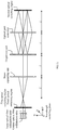
- FIG. 4a is a schematic diagram of an optical path structure of a WSS on a wavelength switching plane according to an embodiment of the present invention.
- FIG. 4b is a schematic diagram of an optical path structure of a WSS on a port switching plane according to an embodiment of the present invention.
- the wavelength switching plane is an XOZ plane
- the port switching plane is a YOZ plane.
- the WSS includes an input optical fiber collimation array 401, a first optical switching engine 402, a dispersion unit 403, an optical path converter 404, a second optical switching engine 405, a third optical switching engine 406, and an output optical fiber collimation array 407.
- An overall optical path is symmetrically distributed around the second optical switching engine 405 as a center.
- the first optical switching engine 402 and the third optical switching engine 406 may be disposed in a same position on an optical axis, and the input optical fiber collimation array and the output optical fiber collimation array may also be disposed in a same position on the optical axis.
- the optical axis is an axis of symmetry of an optical system, that is, a Z-axis direction in FIG. 4a and FIG. 4b .
- the input optical fiber collimation array 401 is configured to input a first beam from a first port of the input optical fiber collimation array 401 and make the first beam incident to the first optical switching engine 402;
- the first optical switching engine 402 is configured to perform angle deflection on the first beam on a first plane according to a first preset angle, so that the first beam is incident to the dispersion unit 403;
- the dispersion unit 403 is configured to demultiplex, on a second plane, the first beam that is incident from the first optical switching engine 402, into multiple sub-wavelength beams, where the second plane and the first plane are orthogonal to each other;
- the optical path converter 404 is configured to refract the multiple sub-wavelength beams that are obtained after the dispersion unit 403 performs demultiplexing onto the second optical switching engine 405;
- the second optical switching engine 405 is configured to perform, according to a second preset angle, angle deflection on the multiple sub-wavelength beams that are obtained after the dispersion
- the first plane may be the port switching plane
- the second plane may be the wavelength switching plane.
- the first beam may be a collimated beam, that is, a parallel beam.
- the first port and the second port may be multiple ports that are arranged in two dimensions, and the first port and the second port may be located in a same row but different columns, in a same column but different rows, or may be located in different rows and different columns.
- the input optical fiber collimation array 401 and the output optical fiber collimation array 407 include an optical fiber array and a collimator array, and input ports in the input optical fiber collimation array 401 and output ports in the output optical fiber collimation array 407 may be PxQ ports that are arranged in two dimensions, where both P and Q are integers greater than or equal to 1.
- Any port of the input optical fiber collimation array 401 and the output optical fiber collimation array 407 may be used as an input port or an output port, or may be used as both an input port and an output port.
- the first port is an input port
- the second port is an output port.
- the first optical switching engine 402, the second optical switching engine 405, and the third optical switching engine 406 include but are not limited to an optical switching engine such as an MEMS (Micro-Electro-Mechanical System, micro-electro-mechanical system), an LCOS (Liquid Crystal on Silicon, liquid crystal on silicon), or DLP (Digital Light Processing, digital light processing).
- an optical switching engine such as an MEMS (Micro-Electro-Mechanical System, micro-electro-mechanical system), an LCOS (Liquid Crystal on Silicon, liquid crystal on silicon), or DLP (Digital Light Processing, digital light processing).
- Multiple optical switching units are in an optical switching engine and are configured to deflect and adjust a direction of a beam.
- the first optical switching engine 402 and the third optical switching engine 406 may not perform angle deflection on a beam.
- the collimated beam output by the input optical fiber collimation array 401 is incident to the dispersion unit 403 in a parallel manner, and the third optical switching engine 406 receives multiple sub-wavelength beams multiplexed by the dispersion unit 403, so that the multiplexed multiple sub-wavelength beams are incident to the output optical fiber collimation array 407 in a parallel manner for output.
- the first optical switching engine 402 and the third optical switching engine 406 may perform angle deflection on a beam.
- the first optical switching engine 402 receives a collimated beam from the input optical fiber collimation array 401, and performs angle deflection on the collimated beam according to the first preset angle, to form a first deflected beam
- the third optical switching engine 406 performs angle deflection on multiplexed multiple sub-wavelength beams according to the third preset angle, to form a third deflected beam, so that the third deflected beam is incident to the output optical fiber collimation array 407 in a parallel manner for output.
- the second optical switching engine 405 is configured to perform, on both the wavelength switching plane and the port switching plane, angle deflection on a beam.
- the second optical switching engine 405 is configured to perform, according to the second preset angle, angle deflection on the multiple sub-wavelength beams that are obtained after the dispersion unit 403 performs demultiplexing, and a formed second deflected beam is incident to different positions in the dispersion unit 403 after being refracted by the optical path converter 404.
- the second optical switching engine 405 performs angle deflection on the first deflected beam according to the second preset angle, and a formed second deflected beam is refracted onto different positions in the third optical switching engine 406 by using the optical path converter 404.
- the first optical switching engine 402, the second optical switching engine 405, and the third optical switching engine 406 each perform angle deflection on a propagation direction of a beam may be implemented by controlling a voltage of the optical switching engine.
- a voltage of the LCOS is controlled, so that a refractive index of the liquid crystal changes and a phase difference is generated.
- the direction of the beam changes when the beam passes through an optical switching unit in the LCOS.
- the first preset angle may be obtained by performing calculation according to a distance between the first optical switching engine 402 and the second optical switching engine 405 and a position of the first deflected beam in the second optical switching engine 405;
- the second preset angle may be obtained by performing calculation according to a distance between the second optical switching engine 405 and the dispersion unit 403 and a position that is in the dispersion unit 403 and to which the second deflected beam is incident after passing through the optical path converter 404, and the second preset angle may alternatively be obtained by performing calculation according to a distance between the second optical switching engine 405 and the third optical switching engine 406 and a position of the second deflected beam in the third optical switching engine 406; and the third preset angle may be set according to an angle at which the third deflected beam is made incident from the third optical switching engine 406 to the output optical fiber collimation array 407 in a parallel manner.
- the first optical switching engine 402 and the third optical switching engine 406 are located in the same position on the optical axis, may be different optical switching units in a same optical switching engine, or may be different optical switching engines.
- the first optical switching engine 402 and the third optical switching engine 406 may include M ⁇ N optical switching units that are arranged in two dimensions, where M is greater than or equal to P, and N is greater than or equal to Q.
- M is greater than or equal to P
- N is greater than or equal to Q
- the optical switching units in the first optical switching engine 402 and the third optical switching engine 406 are corresponding to ports in the input optical fiber collimation array 401 and ports in the output optical fiber collimation array 407 in a one-to-one manner, respectively.
- the second optical switching engine 405 may include T ⁇ K optical switching units, where all of M, N, T, and K are integers greater than or equal to 1, and K is a maximum quantity of sub-wavelengths that are obtained after the dispersion unit 403 performs demultiplexing.
- the dispersion unit 403 is a reflection grating, a transmission grating, or a dispersion prism.
- a combination of multiple gratings may be used, or an optical path may be adjusted to make a beam pass through a same grating for multiple times.
- the dispersion unit mainly performs beam demultiplexing and beam multiplexing on the wavelength switching plane. On the port switching plane, the dispersion unit does not perform beam multiplexing or beam demultiplexing.
- the dispersion unit 403 In a beam incident direction (that is, a direction from the input optical fiber collimation array 401 to the second optical switching engine 405), the dispersion unit 403 is configured to receive the first deflected beam that is obtained after the first optical switching engine 402 performs deflection, and transmit the first deflected beam to the optical path converter 404; and in a beam emergent direction (that is, a direction from the second optical switching engine 405 to the output optical fiber collimation array 407), the dispersion unit 403 is configured to transmit the second deflected beam to the third optical switching engine 406.
- the optical path converter 404 may be a single lens or a lens group that includes multiple lenses.
- the single lens may be a convex lens or a concave mirror.
- the lens group may include multiple convex lenses and/or concave mirrors.
- the single lens or the lens group forms a 2f (f is a focal length of a lens) system.
- the single lens is used as an example.
- the dispersion unit 403 and the second optical switching engine 405 are located on a front focal plane and a back focal plane of the lens, respectively.
- beams that are emitted at different angles from a same position on a focal plane are incident to different positions on an image plane (for example, the second optical switching engine 405) in a parallel manner after passing through the optical path converter 404, and beams that are emitted at a same angle from different positions on a focal plane are incident to a same position on an image plane at different angles after passing through the optical path converter 404.
- sub-wavelength beams that are diffracted according to different angles from a same position in the dispersion unit 403 are emitted in a parallel manner after being refracted by the optical path converter 404, are incident to the second optical switching engine 405 at a same angle, and are incident to different positions in the second optical switching engine 405 according to different wavelength values; and on the wavelength switching plane, sub-wavelength beams that are diffracted at a same angle from different positions in the dispersion unit 403 are incident to a same position in the second optical switching engine 405 at different angles after being refracted by the optical path converter 404.
- the second optical switching engine 405 reflects the multiple sub-wavelength beams according to the second preset angle, and after the formed second deflected beam is refracted by the optical path converter 404, each sub-wavelength beam of the second deflected beam returns to the dispersion unit 403 according to an original emergence angle.
- first deflected beams that are incident from different ports are incident to different positions in the second optical switching engine 405 after being refracted by the optical path converter 404 according to different angles.
- the second optical switching engine 405 performs angle deflection on the first deflected beam according to the second preset angle, the formed second deflected beam is reflected to the optical path converter 404, and the second deflected beam returns to the third optical switching engine 406 according to an original incidence angle after being refracted by the optical path converter 404.
- the first beam is input from the first port of the input optical fiber collimation array, and the first beam is incident to the first optical switching engine; the first optical switching engine performs angle deflection on the first beam on the first plane according to the first preset angle, so that the first beam is incident to the dispersion unit; the dispersion unit demultiplexes, on the second plane, the first beam that is incident from the first optical switching engine, into multiple sub-wavelength beams; the optical path converter refracts the multiple sub-wavelength beams that are obtained after the dispersion unit performs demultiplexing onto the second optical switching engine; the second optical switching engine performs, according to the second preset angle, angle deflection on the multiple sub-wavelength beams that are obtained after the dispersion unit performs demultiplexing, so that the multiple sub-wavelength beams obtained by means of demultiplexing are incident to the dispersion unit by using the optical path converter; the dispersion unit multiplexes, on the second plane, the angle-
- optical switching in two dimensions is implemented on the wavelength switching plane and the port switching plane, input and output ports are arranged in two dimensions, and the ports can reach a large scale in quantity.
- the input and output ports can be switched to each other. Therefore, flexibility of WSS applications can be improved, and a single-fiber bidirectional application scenario can be supported.
- FIG. 5a is a schematic diagram of an optical path structure of another WSS on a wavelength switching plane according to an embodiment of the present invention.
- FIG. 5b is a schematic diagram of an optical path structure of another WSS on a port switching plane according to an embodiment of the present invention.
- FIG. 6a is a schematic diagram of an optical path structure of still another WSS on a wavelength switching plane according to an embodiment of the present invention.
- FIG. 6b is a schematic diagram of an optical path structure of still another WSS on a port switching plane according to an embodiment of the present invention.
- the wavelength switching plane is an XOZ plane
- the port switching plane is a YOZ plane.
- a beam expanding unit is added between a first optical switching engine (or a third optical switching engine) and a dispersion unit, and configured to expand a collimated beam generated by an input optical fiber collimation array and increase a size of a light spot on the dispersion unit, where specifically, on the wavelength switching plane, the beam expanding unit may expand the collimated beam, and on the port switching plane, the beam expanding unit may not have any effect on the collimated beam, and therefore is not shown in the figures; 2 .
- An optical path converter includes a first optical path converter and a second optical path converter, where the first optical path converter performs, on the wavelength switching plane, refraction on multiple sub-wavelength beams that are obtained after the dispersion unit performs demultiplexing, and the second optical path converter performs, on the port switching plane, refraction on a first deflected beam that is obtained after the first optical switching engine performs angle deflection and a second deflected beam that is obtained after a second optical switching engine performs angle deflection.
- the beam expanding unit may be a single lens or a lens group that includes multiple lenses.
- the beam expanding unit may be a first lens
- the first optical path converter may be a second lens
- focal lengths of the first lens and the second lens may be the same
- the first lens and the second lens form a 4f (f is a focal length of a lens) system.
- the first optical switching engine performs angle deflection on the collimated beam output by the input optical fiber collimation array, to generate a converged beam, and a beam convergence point is located on a front focal plane of the first lens.
- the dispersion unit is located on a back focal plane of the first lens and a front focal plane of the second lens.
- the second optical switching engine is located on a back focal plane of the second lens.
- the beam expanding unit may alternatively be a single prism or a prism group that includes multiple prisms.
- the single lens or the lens group expands the collimated beam.
- the first optical path converter and the second optical path converter may use a cylindrical lens.
- FIG. 5a and FIG. 6a show only the first optical path converter
- FIG. 5b and FIG. 6b show only the second optical path converter.
- the first optical path converter may include a single cylindrical lens or a cylindrical lens group that includes multiple cylindrical lenses
- the second optical path converter may include two cylindrical lenses or two cylindrical lens groups that each include multiple cylindrical lenses.
- the dispersion unit is located on a front focal plane of the first optical path converter
- the second optical switching engine is located on a back focal plane of the first optical path converter.
- the second optical path converter may be equivalent to an optical path converter that is in a same position as the dispersion unit.
- the first optical path converter may include a first cylindrical lens
- the second optical path converter may include a second cylindrical lens. Focal lengths of the first cylindrical lens and the second cylindrical lens may be different.
- the dispersion unit is located on a front focal plane of the first cylindrical lens
- the second optical switching engine is located on a back focal plane of the first cylindrical lens.
- a front focal plane of the second cylindrical lens is in a particular position between the first optical switching engine (or the third optical switching engine) and the dispersion unit.
- the particular position is a waist position of an input beam collimated by the input optical fiber collimation array.
- the second optical switching engine is located on a back focal plane of the second cylindrical lens.
- the beam expanding unit is added in the WSS, an area of a light spot of a collimated beam on the dispersion unit is increased, and a dispersion effect of the dispersion unit is enhanced, thereby implementing optical wavelength switching on the wavelength switching plane.
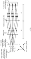
- FIG. 7a is a schematic diagram of an optical path structure of a WSS on a wavelength switching plane according to an embodiment of the present invention.
- FIG. 7b is a schematic diagram of an optical path structure of a WSS on a port switching plane according to an embodiment of the present invention.
- the wavelength switching plane is an XOZ plane
- the port switching plane is a YOZ plane.
- a polarization beam splitter and a half-wave plate are added between an input optical fiber collimation array (or an output optical fiber collimation array) and a first optical switching engine (or a third optical switching engine), where on the wavelength switching plane, a normal of an action plane of the half-wave plate is parallel to or coincides with a propagation direction of a beam that passes through the half-wave plate.
- the polarization beam splitter and the half-wave plate may have an effect only on the wavelength switching plane, and may not have an effect on the port switching plane.
- the polarization beam splitter is configured to split a first beam that is input from a first port of the input optical fiber collimation array into a first sub-beam and a second sub-beam, where the first sub-beam and the second sub-beam have polarization components that are orthogonal to each other.
- the half-wave plate converts the first sub-beam into a beam that has a same orthogonal polarization component as an orthogonal polarization component of the first sub-beam, or the half-wave plate converts the second sub-beam into a parallel beam that has a same orthogonal polarization component as an orthogonal polarization component of the second sub-beam.
- the first sub-beam and the second sub-beam have polarization components that are in a same direction.
- the polarization beam splitter is further configured to multiplex a third sub-beam that is incident from the half-wave plate to the polarization beam splitter and a fourth sub-beam that is incident from the third optical switching engine to the polarization beam splitter, into a beam, where the third sub-beam and the fourth sub-beam have polarization components that are orthogonal to each other.
- the half-wave plate converts the third sub-beam into a beam that has a same orthogonal polarization component as an orthogonal polarization component of the third sub-beam.
- a beam expanding unit may include two lenses, including a first lens and a second lens, and is configured to expand, on the wavelength switching plane, a collimated beam generated by the input optical fiber collimation array, and increase a size of a light spot on a dispersion unit.
- Focal lengths of the first lens and the second lens may be different and may be f1 and f2, respectively.
- the first optical switching engine (the third optical switching engine) is disposed on a front focal plane of the first lens, and the dispersion unit is disposed on a back focal plane of the second lens.
- An interval between the first lens and the second lens is a sum of f1 and f2.
- the two parallel beams After the collimated beam output by the input optical fiber collimation array passes through the polarization beam splitter, two parallel beams whose polarization components are orthogonal to each other are generated. A parallel beam with one polarization component passes through the half-wave plate, and a parallel beam with the other polarization component is directly transmitted from the polarization beam splitter. In this case, the two parallel beams have polarization components that are in a same direction.
- the two parallel beams are incident to the first lens after passing through the first optical switching engine, and converge on a back focal plane of the first lens and a front focal plane of the second lens. After the converged beam is diverged by the second lens, new parallel beams are formed.
- a first optical path converter performs refraction on the wavelength switching plane
- a second optical path converter performs refraction on the port switching plane
- the first optical path converter and the second optical path converter may use a cylindrical lens.
- FIG. 7a shows only the first optical path converter
- FIG. 7b shows only the second optical path converter.
- a focal length of the first optical path converter is f3.
- the focal lengths of the first lens and the second lens in the beam expanding unit are f1 and f2, respectively.
- the polarization beam splitter and the half-wave plate are added in the WSS, implementing optical switching of an input collimated beam in different polarization directions.
- FIG. 8 is an example of a flowchart of a wavelength selection method according to an embodiment of the present invention. The method may be executed by a wavelength selective switch WSS and specifically includes the following steps:
- An input optical fiber collimation array inputs a first beam from a first port of the input optical fiber collimation array and makes the first beam incident from the first port to a first optical switching engine.
- the first optical switching engine performs angle deflection on the first beam on a first plane according to a first preset angle, so that the first beam is incident to a dispersion unit.
- S803 The dispersion unit demultiplexes, on a second plane, the first beam that is incident from the first optical switching engine, into multiple sub-wavelength beams, where the second plane and the first plane are orthogonal to each other.
- S804 An optical path converter refracts the multiple sub-wavelength beams that are obtained after the dispersion unit performs demultiplexing onto a second optical switching engine.
- the second optical switching engine performs, according to a second preset angle, angle deflection on the multiple sub-wavelength beams that are obtained after the dispersion unit performs demultiplexing, so that the multiple sub-wavelength beams obtained by means of demultiplexing are incident to the dispersion unit by using the optical path converter.
- S806 The dispersion unit multiplexes, on the second plane, the angle-deflected multiple sub-wavelength beams that are obtained by means of demultiplexing, and makes the multiplexed multiple sub-wavelength beams incident to a third optical switching engine.
- the third optical switching engine performs angle deflection on the multiplexed multiple sub-wavelength beams on the first plane according to a third preset angle, and outputs the angle-deflected multiplexed multiple sub-wavelength beams from a second port of an output optical fiber collimation array.
- the first plane may be a port switching plane
- the second plane may be a wavelength switching plane.
- the first port and the second port are ports that are arranged in two dimensions, and may be located in different rows but a same column, in a same row but different columns, or in different rows and different columns.
- a total quantity of first ports and second ports may be P ⁇ Q.
- the input optical fiber collimation array and the output optical fiber collimation array are located in a same position on an optical axis, and the first optical switching engine and the third optical switching engine are located in a same position on the optical axis.
- the first optical switching engine and the third optical switching engine may include a total of P ⁇ Q optical switching units that are arranged in two dimensions, where P and Q are integers greater than or equal to 1.
- the first optical switching engine and the third optical switching engine perform angle deflection on the first beam on the first plane, and the dispersion unit performs, on the second plane, first-beam demultiplexing, and beam multiplexing to form the first beam, so that optical switching in two dimensions is implemented, input and output ports are arranged in two dimensions, and ports can reach a large scale in quantity.
- the input and output ports can be switched to each other. Therefore, flexibility of WSS applications can be improved, and a single-fiber bidirectional application scenario can be supported.
- each aspect of the present invention or a possible implementation of each aspect may be specifically implemented as a system, a method, or a computer program product. Therefore, each aspect of the present invention or a possible implementation of each aspect may use forms of hardware only embodiments, software only embodiments (including firmware, resident software, and the like), or embodiments with a combination of software and hardware, which are uniformly referred to as "circuit", "module”, or “system” herein.
- each aspect of the present invention or a possible implementation of each aspect may take a form of a computer program product, where the computer program product refers to computer-readable program code stored in a computer-readable medium.
- the computer-readable medium may be a computer-readable signal medium or a computer-readable storage medium.
- the computer-readable storage medium includes but is not limited to an electronic, magnetic, optical, electromagnetic, infrared, or semi-conductive system, device, or apparatus, or any appropriate combination thereof, such as a random access memory (RAM), a read-only memory (ROM), an erasable programmable read only memory (EPROM or flash memory), an optical fiber, and a compact disc read only memory (CD-ROM).
- a processor in a computer reads computer-readable program code stored in a computer-readable medium, so that the processor can perform a function and an action specified in each step or a combination of steps in a flowchart, and an apparatus is generated to implement a function and an action specified in each block or a combination of blocks in a block diagram.
- All computer-readable program code may be executed on a user computer, or some may be executed on a user computer as a standalone software package, or some may be executed on a user computer while some is executed on a remote computer, or all the code may be executed on a remote computer or a server. It should also be noted that, in some alternative implementation solutions, each step in the flowcharts or functions specified in each block in the block diagrams may not occur in the illustrated order. For example, two consecutive steps or two blocks in the illustration, which are dependent on an involved function, may in fact be executed substantially at the same time, or these blocks may sometimes be executed in reverse order.
Description
- The present invention relates to the communications field, and in particular, to a wavelength selective switch, a reconfigurable optical add/drop multiplexer, and a wavelength selection method.
- With rapid development of ROADM (Reconfigurable Optical Add-Drop Multiplexer, reconfigurable optical add/drop multiplexer) technologies, a colorless (colorless), directionless (directionless), and contentionless (contentionless) ROADM (CDC ROADM for short) is a development direction of a future ROADM architecture. Colorless means that any port can be used for outputting any wavelength, directionless means that any wavelength can be scheduled to any direction, and contentionless means that there is no wavelength conflict when a same wavelength needs to be locally added and dropped simultaneously in multiple directions.
- In the prior art, as shown in
FIG. 1 , an ROADM architecture includes a line-side wavelength switching module and a client-side wavelength switching module. The line-side wavelength switching module is connected to the client-side wavelength switching module by using an optical fiber. The line-side wavelength switching module may include multiple WSSs (Wavelength Selective Switch, wavelength selective switch) and SPs (Splitter, splitter). One WSS and one SP constitute a wavelength switching sub-module in one direction.FIG. 1 shows wavelength switching sub-modules in three directions, including an east (east) dimension, a west (west) dimension, and a north (north) dimension. The client-side wavelength switching module includes an add module and a drop module. The add module includes multiple TX transmitters and one WSS, and the drop module includes multiple RX receivers and one WSS. The east dimension is used as an example. For a WDM (Wavelength Division Multiplex, wavelength division multiplexing) optical signal input from the east dimension, the optical signal is first broadcast to other several dimensions and the client-side drop module by using an SP. For a wavelength that needs to be locally downloaded from the client side, the client-side drop module selects and receives the wavelength. For a wavelength that needs to be transferred from a WSS in the east dimension to a WSS in the west dimension, the WSS in the west dimension selects the wavelength and transfers the wavelength, and blocks wavelengths that are from other dimensions. - A WSS in the prior art has beam multiplexing and beam demultiplexing functions.
FIG. 2a is a schematic diagram of a top view of an optical path structure of an N×M WSS in the prior art.FIG. 2b is a schematic diagram of a side view of an optical path structure of an N×M WSS in the prior art. As shown inFIG. 2a andFIG. 2b , a WDM signal is input from an input port 201 (an input optical fiber), is collimated by acollimator array 202, and is demultiplexed into K sub-wavelength signals by a first-stage grating 203. The K sub-wavelength signals are incident to a first-stageoptical switching array 206 after passing through acylindrical lens array 204 and alens 205. The first-stageoptical switching array 206 has N rows, and there are K optical switch units in each row. Each optical switch unit deflects one sub-wavelength signal, so that the sub-wavelength signal is incident to a corresponding optical switch unit in a second-stageoptical switching array 207. The second-stageoptical switching array 207 has M rows, and there are K optical switch units in each row. Each optical switch unit is corresponding to one sub-wavelength signal. The optical switch unit corrects an angle of the sub-wavelength signal, so that the sub-wavelength signal is parallel to a direction of an optical axis (Z) in a Y direction. All sub-wavelength signals are incident to a second-stage grating 210 after passing through alens 208 and acylindrical lens array 209, output to acollimator array 207 after being multiplexed by the second-stage grating 210, and finally output from an output port 208 (an output optical fiber). Actually, the first-stageoptical switching array 206 and the second-stageoptical switching array 207 perform optical switching only on a Y plane, and each optical switch unit implements a wavelength selection function by performing deflection in one dimension. The first-stage grating 203 and the first-stageoptical switching array 206 implement a "beam demultiplexing" function, and switch the sub-wavelength signals from the same input port to different optical switch units in the second-stageoptical switching array 207. The second-stageoptical switching array 207 and the second-stage grating 210 implement a "beam multiplexing" function. - The second-stage optical switching array in the prior art requires M×K switch switching units. The K switch units occupy spatial positions in an X direction, and K is a relatively large integer. As a result, optical switching cannot be implemented in two dimensions. Therefore, output ports are restricted in one dimension and cannot be arranged in two dimensions, each output port is corresponding to the K optical switch units, and a quantity of the output ports is restricted.
-
WO 2015/008403 A1 discloses an optical path control device, the optical path control device has a light input section 1, ananamorphic converter 2, adispersive element 5, an optical power element 6, optical deflectors 7 a and 7 b, and a light output section 13. To the light input section 1, wavelength-multiplexed beams L1 a, L1 b are input from the outside of the optical path control device 100. Each of the wavelength-multiplexed beams L1 a, L1 b travels through theanamorphic converter 2,dispersive element 5, and optical power element 6 in this order, is then deflected by either of the optical deflectors 7 a and 7 b, and travels through the optical power element 6,dispersive element 5, andanamorphic converter 2 in this order to be output from the light output section 13. -
US 2012/237218 A1 discloses optical switches including collimator elements that accommodate two or more optical ports. The collimator element of D2 include a lens. Inbound multi-channel optical signals are guided to the lens by different optical paths configured such that the lens deflects the optical signals at angles that are determined by the optical paths, the optical paths are implemented using optical fibers or optical waveguides. - In view of this, embodiments of the present invention provide a wavelength selective switch, a reconfigurable optical add/drop multiplexer, and a wavelength selection method, so as to resolve a problem that output ports of a WSS cannot be arranged in two dimensions and a quantity of the output ports is restricted.
- According to a first aspect, an embodiment of the present invention provides a wavelength selective switch WSS, including an input optical fiber collimation array, a first optical switching engine, a dispersion unit, an optical path converter, a second optical switching engine, a third optical switching engine, and an output optical fiber collimation array, where the input optical fiber collimation array is configured to input a first beam from a first port of the input optical fiber collimation array and make the first beam incident to the first optical switching engine; the first optical switching engine is configured to perform angle deflection on the first beam on a first plane according to a first preset angle, so that the first beam is incident to the dispersion unit; the dispersion unit is configured to demultiplex, on a second plane, the first beam that is incident from the first optical switching engine, into multiple sub-wavelength beams, where the second plane and the first plane are orthogonal to each other; the optical path converter is configured to refract the multiple sub-wavelength beams that are obtained after the dispersion unit performs demultiplexing onto the second optical switching engine; the second optical switching engine is configured to perform, according to a second preset angle, angle deflection on the multiple sub-wavelength beams that are obtained after the dispersion unit performs demultiplexing, so that the multiple sub-wavelength beams obtained by means of demultiplexing are incident to the dispersion unit by using the optical path converter; the dispersion unit is further configured to multiplex, on the second plane, the angle-deflected multiple sub-wavelength beams that are obtained by means of demultiplexing, and make the multiplexed multiple sub-wavelength beams incident to the third optical switching engine; and the third optical switching engine is configured to perform angle deflection on the multiplexed multiple sub-wavelength beams on the first plane according to a third preset angle, and output the angle-deflected multiplexed multiple sub-wavelength beams from a second port of the output optical fiber collimation array, wherein the third optical switching engine performing angle deflection on the multiplexed multiple sub-wavelength beams is implemented by controlling a voltage of the third optical switching engine.
- With reference to the implementation of the first aspect, in a first possible implementation of the first aspect, the first port and the second port are ports that are arranged in two dimensions, and the first port and the second port are in different rows and/or columns.
- With reference to the first aspect or the first possible implementation of the first aspect, in a second possible implementation of the first aspect, the input optical fiber collimation array and the output optical fiber collimation array are located in a same position on an optical axis, and the first optical switching engine and the third optical switching engine are located in a same position on the optical axis.
- With reference to any one of the first aspect or the first and the second possible implementations of the first aspect, in a third possible implementation of the first aspect, a total quantity of first ports in the input optical fiber collimation array and second ports in the output optical fiber collimation array is P×Q, and the first optical switching engine and the third optical switching engine include a total of P×Q optical switching units that are arranged in two dimensions, where P and Q are integers greater than or equal to 1.
- With reference to any one of the first aspect or the first to the third possible implementations of the first aspect, in a fourth possible implementation of the first aspect, the dispersion unit is located on a front focal plane of the optical path converter, and the second optical switching engine is located on a back focal plane of the optical path converter.
- With reference to any one of the first aspect or the first to the fourth possible implementations of the first aspect, in a fifth possible implementation of the first aspect, the optical path converter includes a first optical path converter and a second optical path converter, the first optical path converter performs refraction on the first plane, and the second optical path converter performs refraction on the second plane.
- With reference to any one of the first aspect or the first to the fifth possible implementations of the first aspect, in a sixth possible implementation of the first aspect, a beam expanding unit is further included between the first optical switching engine and the dispersion unit, and the beam expanding unit is configured to receive the first beam on which the first optical switching engine has performed angle deflection on the first plane, and expand the first beam on the second plane.
- With reference to any one of the first aspect or the first to the sixth possible implementations of the first aspect, in a seventh possible implementation of the first aspect, the beam expanding unit includes a first lens, and the first optical path converter includes a second lens; the first beam on which the first optical switching engine has performed angle deflection on the second plane converges on a front focal plane of the first lens; the dispersion unit is located on a back focal plane of the first lens and on a front focal plane of the second lens; and the second optical switching engine is located on a back focal plane of the second lens.
- With reference to any one of the first aspect or the first to the seventh possible implementations of the first aspect, in an eighth possible implementation of the first aspect, the beam expanding unit includes a third lens and a fourth lens, the first optical switching engine is located on a front focal plane of the third lens, the dispersion unit is located on a back focal plane of the fourth lens, and a distance between the third lens and the fourth lens is a sum of focal lengths of the third lens and the fourth lens.
- With reference to any one of the first aspect or the first to the eighth possible implementations of the first aspect, in a ninth possible implementation of the first aspect, a polarization beam splitter and a half-wave plate are further included between the input optical fiber collimation array and the first optical switching engine; the polarization beam splitter is configured to split, on the second plane, the first beam from the first port of the input optical fiber collimation array into a first sub-beam and a second sub-beam, where the first sub-beam and the second sub-beam have polarization components that are orthogonal to each other; the polarization beam splitter is further configured to multiplex, on the second plane, a third sub-beam that is incident from the half-wave plate to the polarization beam splitter and a fourth sub-beam that is incident from the third optical switching engine to the polarization beam splitter, into a beam, where the third sub-beam and the fourth sub-beam have polarization components that are orthogonal to each other; and a normal of an action plane of the half-wave plate is parallel to or coincides with propagation directions of the first sub-beam and the third sub-beam, the half-wave plate is configured to convert the first sub-beam into a beam that has a same orthogonal polarization component as an orthogonal polarization component of the first sub-beam, and the half-wave plate is further configured to convert the third sub-beam into a beam that has a same orthogonal polarization component as an orthogonal polarization component of the third sub-beam.
- With reference to any one of the first aspect or the first to the ninth possible implementations of the first aspect, in a tenth possible implementation of the first aspect, central axes of the input optical fiber collimation array, the first optical switching engine, the dispersion unit, the optical path converter, the second optical switching engine, the third optical switching engine, and the output optical fiber collimation array are parallel to a direction of the optical axis.
- According to a second aspect, an embodiment of the present invention provides a reconfigurable optical add/drop multiplexer ROADM, where the ROADM includes a first WSS, a second WSS, an add module, and a drop module, and the second WSS is the WSS according to any one of the first aspect or any possible implementation of the first aspect; and the first WSS is configured to receive an optical signal and demultiplex the received optical signal into at least two optical signals of different wavelengths, the second WSS is configured to perform wavelength switching on the at least two optical signals of different wavelengths on multiple input ports and multiple output ports, the add module is configured to upload a local wavelength signal to the multiple input ports of the second WSS, and the drop module is configured to download a local wavelength signal from the multiple output ports of the second WSS.
- According to a third aspect, an embodiment of the present invention provides a wavelength selection method, where the method includes: inputting, by an input optical fiber collimation array, a first beam from a first port, and making the first beam incident from the first port to a first optical switching engine; performing, by the first optical switching engine, angle deflection on the first beam on a first plane according to a first preset angle, so that the first beam is incident to a dispersion unit; demultiplexing, by the dispersion unit, on a second plane, the first beam that is incident from the first optical switching engine, into multiple sub-wavelength beams, where the second plane and the first plane are orthogonal to each other; refracting, by an optical path converter, the multiple sub-wavelength beams that are obtained after the dispersion unit performs demultiplexing onto a second optical switching engine; performing, by the second optical switching engine according to a second preset angle, angle deflection on the multiple sub-wavelength beams that are obtained after the dispersion unit performs demultiplexing, so that the multiple sub-wavelength beams obtained by means of demultiplexing are incident to the dispersion unit by using the optical path converter; multiplexing, by the dispersion unit, on the second plane, the angle-deflected multiple sub-wavelength beams that are obtained by means of demultiplexing, and making the multiplexed multiple sub-wavelength beams incident to a third optical switching engine; and performing, by the third optical switching engine, angle deflection on the multiplexed multiple sub-wavelength beams on the first plane according to a third preset angle, and outputting the angle-deflected multiplexed multiple sub-wavelength beams from a second port of an output optical fiber collimation array, wherein the third optical switching engine performing angle deflection on the multiplexed multiple sub-wavelength beams is implemented by controlling a voltage of the third optical switching engine.
- According to the technical solutions provided by the embodiments of the present invention, the first beam is input from the first port of the input optical fiber collimation array, and the first beam is incident to the first optical switching engine; the first optical switching engine performs angle deflection on the first beam on the first plane according to the first preset angle, so that the first beam is incident to the dispersion unit; the dispersion unit demultiplexes, on the second plane, the first beam that is incident from the first optical switching engine, into multiple sub-wavelength beams; the optical path converter refracts the multiple sub-wavelength beams that are obtained after the dispersion unit performs demultiplexing onto the second optical switching engine; the second optical switching engine performs, according to the second preset angle, angle deflection on the multiple sub-wavelength beams that are obtained after the dispersion unit performs demultiplexing, so that the multiple sub-wavelength beams obtained by means of demultiplexing are incident to the dispersion unit by using the optical path converter; the dispersion unit multiplexes, on the second plane, the angle-deflected multiple sub-wavelength beams that are obtained by means of demultiplexing, and makes the multiplexed multiple sub-wavelength beams incident to the third optical switching engine; and the third optical switching engine performs angle deflection on the multiplexed multiple sub-wavelength beams on the first plane according to the third preset angle, and outputs the angle-deflected multiplexed multiple sub-wavelength beams from the second port of the output optical fiber collimation array. Optical switching in two dimensions is implemented on the first plane and the second plane, input ports and ports are arranged in two dimensions, and the input and output ports can reach a large scale in quantity.
- To describe the technical solutions in the embodiments of the present invention or in the prior art more clearly, the following briefly describes the accompanying drawings required for describing the background and the embodiments.
-
FIG. 1 is a schematic diagram of a reconfigurable optical add/drop multiplexer ROADM architecture in the prior art; -
FIG. 2a is a schematic diagram of a top view of an optical path structure of an N×M WSS in the prior art; -
FIG. 2b is a schematic diagram of a side view of an optical path structure of an N×M WSS in the prior art; -
FIG. 3 is a schematic diagram of an ROADM architecture according to an embodiment of the present invention; -
FIG. 4a is a schematic diagram of an optical path structure of a WSS on a wavelength switching plane according to an embodiment of the present invention; -
FIG. 4b is a schematic diagram of an optical path structure of a WSS on a port switching plane according to an embodiment of the present invention; -
FIG. 5a is a schematic diagram of an optical path structure of another WSS on a wavelength switching plane according to an embodiment of the present invention; -
FIG. 5b is a schematic diagram of an optical path structure of another WSS on a port switching plane according to an embodiment of the present invention; -
FIG. 6a is a schematic diagram of an optical path structure of still another WSS on a wavelength switching plane according to an embodiment of the present invention; -
FIG. 6b is a schematic diagram of an optical path structure of still another WSS on a port switching plane according to an embodiment of the present invention; -
FIG. 7a is a schematic diagram of an optical path structure of a WSS on a wavelength switching plane according to an embodiment of the present invention; -
FIG. 7b is a schematic diagram of an optical path structure of a WSS on a port switching plane according to an embodiment of the present invention; and -
FIG. 8 is an example of a flowchart of a wavelength selection method according to an embodiment of the present invention. - To make the objectives, technical solutions, and advantages of the present invention clearer and more comprehensible, the following further describes the present invention in detail with reference to the accompanying drawings and embodiments. It should be understood that the specific embodiments described herein are merely used to explain the present invention but are not intended to limit the present invention.
-
FIG. 3 is a schematic diagram of an ROADM architecture according to an embodiment of the present invention. As shown inFIG. 3 , the ROADM architecture according to this embodiment of the present invention includes multiplefirst WSSs 301, asecond WSS 302, anadd module 303, and adrop module 304. - Specifically, the
first WSS 301 may be a 1×N WSS in the prior art. Thefirst WSS 301 is configured to receive a line-side wavelength signal and demultiplex the received wavelength signal into multiple signals of different wavelengths. Thesecond WSS 302 is configured to implement beam multiplexing and beam demultiplexing functions, and perform wavelength selection and switching on an input port and an output port, to implement flexible wavelength scheduling in different directions. A structure of thesecond WSS 302 in this embodiment of the present invention is different from a structure of thefirst WSS 301 in the prior art. The specific structure of thesecond WSS 302 is described in detail in the following embodiments. Theadd module 303 includes multiple TX transmitters and is configured to upload a client-side local wavelength signal to an input port of thesecond WSS 302. The drop module includes multiple RX receivers and is configured to download a client-side local wavelength signal from an output port of thesecond WSS 302. -
FIG. 4a is a schematic diagram of an optical path structure of a WSS on a wavelength switching plane according to an embodiment of the present invention.FIG. 4b is a schematic diagram of an optical path structure of a WSS on a port switching plane according to an embodiment of the present invention. The wavelength switching plane is an XOZ plane, and the port switching plane is a YOZ plane. Specifically, as shown inFIG. 4a andFIG. 4b , the WSS includes an input opticalfiber collimation array 401, a firstoptical switching engine 402, adispersion unit 403, anoptical path converter 404, a secondoptical switching engine 405, a thirdoptical switching engine 406, and an output opticalfiber collimation array 407. An overall optical path is symmetrically distributed around the secondoptical switching engine 405 as a center. The firstoptical switching engine 402 and the thirdoptical switching engine 406 may be disposed in a same position on an optical axis, and the input optical fiber collimation array and the output optical fiber collimation array may also be disposed in a same position on the optical axis. The optical axis is an axis of symmetry of an optical system, that is, a Z-axis direction inFIG. 4a andFIG. 4b . - In a specific implementation process, the input optical fiber collimation array 401 is configured to input a first beam from a first port of the input optical fiber collimation array 401 and make the first beam incident to the first optical switching engine 402; the first optical switching engine 402 is configured to perform angle deflection on the first beam on a first plane according to a first preset angle, so that the first beam is incident to the dispersion unit 403; the dispersion unit 403 is configured to demultiplex, on a second plane, the first beam that is incident from the first optical switching engine 402, into multiple sub-wavelength beams, where the second plane and the first plane are orthogonal to each other; the optical path converter 404 is configured to refract the multiple sub-wavelength beams that are obtained after the dispersion unit 403 performs demultiplexing onto the second optical switching engine 405; the second optical switching engine 405 is configured to perform, according to a second preset angle, angle deflection on the multiple sub-wavelength beams that are obtained after the dispersion unit 403 performs demultiplexing, so that the multiple sub-wavelength beams obtained by means of demultiplexing are incident to the dispersion unit 403 by using the optical path converter 404; the dispersion unit 403 is further configured to multiplex, on the second plane, the angle-deflected multiple sub-wavelength beams that are obtained by means of demultiplexing, and make the multiplexed multiple sub-wavelength beams incident to the third optical switching engine 406; and the third optical switching engine 406 is configured to perform angle deflection on the multiplexed multiple sub-wavelength beams on the first plane according to a third preset angle, and output the angle-deflected multiplexed multiple sub-wavelength beams from a second port of the output optical fiber collimation array 407. Specifically, the first plane may be the port switching plane, and the second plane may be the wavelength switching plane. The first beam may be a collimated beam, that is, a parallel beam. The first port and the second port may be multiple ports that are arranged in two dimensions, and the first port and the second port may be located in a same row but different columns, in a same column but different rows, or may be located in different rows and different columns.
- Specifically, the input optical
fiber collimation array 401 and the output opticalfiber collimation array 407 include an optical fiber array and a collimator array, and input ports in the input opticalfiber collimation array 401 and output ports in the output opticalfiber collimation array 407 may be PxQ ports that are arranged in two dimensions, where both P and Q are integers greater than or equal to 1. Any port of the input opticalfiber collimation array 401 and the output opticalfiber collimation array 407 may be used as an input port or an output port, or may be used as both an input port and an output port. In this embodiment, the first port is an input port, and the second port is an output port. - The first
optical switching engine 402, the secondoptical switching engine 405, and the thirdoptical switching engine 406 include but are not limited to an optical switching engine such as an MEMS (Micro-Electro-Mechanical System, micro-electro-mechanical system), an LCOS (Liquid Crystal on Silicon, liquid crystal on silicon), or DLP (Digital Light Processing, digital light processing). Multiple optical switching units are in an optical switching engine and are configured to deflect and adjust a direction of a beam. On the wavelength switching plane, the firstoptical switching engine 402 and the thirdoptical switching engine 406 may not perform angle deflection on a beam. For example, after passing through the firstoptical switching engine 402, the collimated beam output by the input opticalfiber collimation array 401 is incident to thedispersion unit 403 in a parallel manner, and the thirdoptical switching engine 406 receives multiple sub-wavelength beams multiplexed by thedispersion unit 403, so that the multiplexed multiple sub-wavelength beams are incident to the output opticalfiber collimation array 407 in a parallel manner for output. On the port switching plane, the firstoptical switching engine 402 and the thirdoptical switching engine 406 may perform angle deflection on a beam. For example, the firstoptical switching engine 402 receives a collimated beam from the input opticalfiber collimation array 401, and performs angle deflection on the collimated beam according to the first preset angle, to form a first deflected beam, and the thirdoptical switching engine 406 performs angle deflection on multiplexed multiple sub-wavelength beams according to the third preset angle, to form a third deflected beam, so that the third deflected beam is incident to the output opticalfiber collimation array 407 in a parallel manner for output. The secondoptical switching engine 405 is configured to perform, on both the wavelength switching plane and the port switching plane, angle deflection on a beam. On the wavelength switching plane, the secondoptical switching engine 405 is configured to perform, according to the second preset angle, angle deflection on the multiple sub-wavelength beams that are obtained after thedispersion unit 403 performs demultiplexing, and a formed second deflected beam is incident to different positions in thedispersion unit 403 after being refracted by theoptical path converter 404. On the port switching plane, the secondoptical switching engine 405 performs angle deflection on the first deflected beam according to the second preset angle, and a formed second deflected beam is refracted onto different positions in the thirdoptical switching engine 406 by using theoptical path converter 404. - Specifically, that the first
optical switching engine 402, the secondoptical switching engine 405, and the thirdoptical switching engine 406 each perform angle deflection on a propagation direction of a beam may be implemented by controlling a voltage of the optical switching engine. For example, for an LCOS, a voltage of the LCOS is controlled, so that a refractive index of the liquid crystal changes and a phase difference is generated. In this case, the direction of the beam changes when the beam passes through an optical switching unit in the LCOS. Specifically, the first preset angle may be obtained by performing calculation according to a distance between the firstoptical switching engine 402 and the secondoptical switching engine 405 and a position of the first deflected beam in the secondoptical switching engine 405; the second preset angle may be obtained by performing calculation according to a distance between the secondoptical switching engine 405 and thedispersion unit 403 and a position that is in thedispersion unit 403 and to which the second deflected beam is incident after passing through theoptical path converter 404, and the second preset angle may alternatively be obtained by performing calculation according to a distance between the secondoptical switching engine 405 and the thirdoptical switching engine 406 and a position of the second deflected beam in the thirdoptical switching engine 406; and the third preset angle may be set according to an angle at which the third deflected beam is made incident from the thirdoptical switching engine 406 to the output opticalfiber collimation array 407 in a parallel manner. - The first
optical switching engine 402 and the thirdoptical switching engine 406 are located in the same position on the optical axis, may be different optical switching units in a same optical switching engine, or may be different optical switching engines. Specifically, the firstoptical switching engine 402 and the thirdoptical switching engine 406 may include M×N optical switching units that are arranged in two dimensions, where M is greater than or equal to P, and N is greater than or equal to Q. When M is equal to P and N is equal to Q, the optical switching units in the firstoptical switching engine 402 and the thirdoptical switching engine 406 are corresponding to ports in the input opticalfiber collimation array 401 and ports in the output opticalfiber collimation array 407 in a one-to-one manner, respectively. The secondoptical switching engine 405 may include T×K optical switching units, where all of M, N, T, and K are integers greater than or equal to 1, and K is a maximum quantity of sub-wavelengths that are obtained after thedispersion unit 403 performs demultiplexing. - The
dispersion unit 403 is a reflection grating, a transmission grating, or a dispersion prism. Optionally, to increase a dispersion effect, a combination of multiple gratings may be used, or an optical path may be adjusted to make a beam pass through a same grating for multiple times. The dispersion unit mainly performs beam demultiplexing and beam multiplexing on the wavelength switching plane. On the port switching plane, the dispersion unit does not perform beam multiplexing or beam demultiplexing. In a beam incident direction (that is, a direction from the input opticalfiber collimation array 401 to the second optical switching engine 405), thedispersion unit 403 is configured to receive the first deflected beam that is obtained after the firstoptical switching engine 402 performs deflection, and transmit the first deflected beam to theoptical path converter 404; and in a beam emergent direction (that is, a direction from the secondoptical switching engine 405 to the output optical fiber collimation array 407), thedispersion unit 403 is configured to transmit the second deflected beam to the thirdoptical switching engine 406. - The
optical path converter 404 may be a single lens or a lens group that includes multiple lenses. The single lens may be a convex lens or a concave mirror. The lens group may include multiple convex lenses and/or concave mirrors. Specifically, the single lens or the lens group forms a 2f (f is a focal length of a lens) system. The single lens is used as an example. Thedispersion unit 403 and the secondoptical switching engine 405 are located on a front focal plane and a back focal plane of the lens, respectively. According to an imaging principle of geometrical optics, beams that are emitted at different angles from a same position on a focal plane (for example, a front focal plane) are incident to different positions on an image plane (for example, the second optical switching engine 405) in a parallel manner after passing through theoptical path converter 404, and beams that are emitted at a same angle from different positions on a focal plane are incident to a same position on an image plane at different angles after passing through theoptical path converter 404. Specifically, on the wavelength switching plane, sub-wavelength beams that are diffracted according to different angles from a same position in thedispersion unit 403 are emitted in a parallel manner after being refracted by theoptical path converter 404, are incident to the secondoptical switching engine 405 at a same angle, and are incident to different positions in the secondoptical switching engine 405 according to different wavelength values; and on the wavelength switching plane, sub-wavelength beams that are diffracted at a same angle from different positions in thedispersion unit 403 are incident to a same position in the secondoptical switching engine 405 at different angles after being refracted by theoptical path converter 404. On the wavelength switching plane, the secondoptical switching engine 405 reflects the multiple sub-wavelength beams according to the second preset angle, and after the formed second deflected beam is refracted by theoptical path converter 404, each sub-wavelength beam of the second deflected beam returns to thedispersion unit 403 according to an original emergence angle. On the port switching plane, first deflected beams that are incident from different ports are incident to different positions in the secondoptical switching engine 405 after being refracted by theoptical path converter 404 according to different angles. The secondoptical switching engine 405 performs angle deflection on the first deflected beam according to the second preset angle, the formed second deflected beam is reflected to theoptical path converter 404, and the second deflected beam returns to the thirdoptical switching engine 406 according to an original incidence angle after being refracted by theoptical path converter 404. - In the embodiments of the present invention, the first beam is input from the first port of the input optical fiber collimation array, and the first beam is incident to the first optical switching engine; the first optical switching engine performs angle deflection on the first beam on the first plane according to the first preset angle, so that the first beam is incident to the dispersion unit; the dispersion unit demultiplexes, on the second plane, the first beam that is incident from the first optical switching engine, into multiple sub-wavelength beams; the optical path converter refracts the multiple sub-wavelength beams that are obtained after the dispersion unit performs demultiplexing onto the second optical switching engine; the second optical switching engine performs, according to the second preset angle, angle deflection on the multiple sub-wavelength beams that are obtained after the dispersion unit performs demultiplexing, so that the multiple sub-wavelength beams obtained by means of demultiplexing are incident to the dispersion unit by using the optical path converter; the dispersion unit multiplexes, on the second plane, the angle-deflected multiple sub-wavelength beams that are obtained by means of demultiplexing, and makes the multiplexed multiple sub-wavelength beams incident to the third optical switching engine; and the third optical switching engine performs angle deflection on the multiplexed multiple sub-wavelength beams on the first plane according to the third preset angle, and outputs the angle-deflected multiplexed multiple sub-wavelength beams from the second port of the output optical fiber collimation array. In the embodiments of the present invention, optical switching in two dimensions is implemented on the wavelength switching plane and the port switching plane, input and output ports are arranged in two dimensions, and the ports can reach a large scale in quantity. In addition, the input and output ports can be switched to each other. Therefore, flexibility of WSS applications can be improved, and a single-fiber bidirectional application scenario can be supported.
-
FIG. 5a is a schematic diagram of an optical path structure of another WSS on a wavelength switching plane according to an embodiment of the present invention.FIG. 5b is a schematic diagram of an optical path structure of another WSS on a port switching plane according to an embodiment of the present invention.FIG. 6a is a schematic diagram of an optical path structure of still another WSS on a wavelength switching plane according to an embodiment of the present invention.FIG. 6b is a schematic diagram of an optical path structure of still another WSS on a port switching plane according to an embodiment of the present invention. The wavelength switching plane is an XOZ plane, and the port switching plane is a YOZ plane. Specifically, differences between the embodiments shown inFIG. 5a ,FIG. 5b ,FIG. 6a , andFIG. 6b and the embodiments shown inFIG. 4a andFIG. 4b are as follows: 1. A beam expanding unit is added between a first optical switching engine (or a third optical switching engine) and a dispersion unit, and configured to expand a collimated beam generated by an input optical fiber collimation array and increase a size of a light spot on the dispersion unit, where specifically, on the wavelength switching plane, the beam expanding unit may expand the collimated beam, and on the port switching plane, the beam expanding unit may not have any effect on the collimated beam, and therefore is not shown in thefigures; 2 . An optical path converter includes a first optical path converter and a second optical path converter, where the first optical path converter performs, on the wavelength switching plane, refraction on multiple sub-wavelength beams that are obtained after the dispersion unit performs demultiplexing, and the second optical path converter performs, on the port switching plane, refraction on a first deflected beam that is obtained after the first optical switching engine performs angle deflection and a second deflected beam that is obtained after a second optical switching engine performs angle deflection. - Specifically, as shown in
FIG. 5a , the beam expanding unit may be a single lens or a lens group that includes multiple lenses. The beam expanding unit may be a first lens, the first optical path converter may be a second lens, focal lengths of the first lens and the second lens may be the same, and the first lens and the second lens form a 4f (f is a focal length of a lens) system. On the wavelength switching plane, the first optical switching engine performs angle deflection on the collimated beam output by the input optical fiber collimation array, to generate a converged beam, and a beam convergence point is located on a front focal plane of the first lens. The dispersion unit is located on a back focal plane of the first lens and a front focal plane of the second lens. The second optical switching engine is located on a back focal plane of the second lens. As shown inFIG. 6a , the beam expanding unit may alternatively be a single prism or a prism group that includes multiple prisms. On the wavelength switching plane, after the collimated beam output by the input optical fiber collimation array passes through the first optical switching engine, the single lens or the lens group expands the collimated beam. - Because the first optical path converter performs refraction on the wavelength switching plane and the second optical path converter performs refraction on the port switching plane, the first optical path converter and the second optical path converter may use a cylindrical lens.
FIG. 5a andFIG. 6a show only the first optical path converter, andFIG. 5b andFIG. 6b show only the second optical path converter. As shown inFIG. 5a andFIG. 5b , the first optical path converter may include a single cylindrical lens or a cylindrical lens group that includes multiple cylindrical lenses, and the second optical path converter may include two cylindrical lenses or two cylindrical lens groups that each include multiple cylindrical lenses. The dispersion unit is located on a front focal plane of the first optical path converter, and the second optical switching engine is located on a back focal plane of the first optical path converter. The second optical path converter may be equivalent to an optical path converter that is in a same position as the dispersion unit. As shown inFIG. 6a andFIG. 6b , the first optical path converter may include a first cylindrical lens, and the second optical path converter may include a second cylindrical lens. Focal lengths of the first cylindrical lens and the second cylindrical lens may be different. The dispersion unit is located on a front focal plane of the first cylindrical lens, and the second optical switching engine is located on a back focal plane of the first cylindrical lens. A front focal plane of the second cylindrical lens is in a particular position between the first optical switching engine (or the third optical switching engine) and the dispersion unit. The particular position is a waist position of an input beam collimated by the input optical fiber collimation array. The second optical switching engine is located on a back focal plane of the second cylindrical lens. - In the embodiments of the present invention, the beam expanding unit is added in the WSS, an area of a light spot of a collimated beam on the dispersion unit is increased, and a dispersion effect of the dispersion unit is enhanced, thereby implementing optical wavelength switching on the wavelength switching plane.
-
FIG. 7a is a schematic diagram of an optical path structure of a WSS on a wavelength switching plane according to an embodiment of the present invention.FIG. 7b is a schematic diagram of an optical path structure of a WSS on a port switching plane according to an embodiment of the present invention. The wavelength switching plane is an XOZ plane, and the port switching plane is a YOZ plane. Specifically, a difference between the embodiments shown inFIG. 7a andFIG. 7b and the embodiments shown inFIG. 5a andFIG. 5b is as follows: A polarization beam splitter and a half-wave plate are added between an input optical fiber collimation array (or an output optical fiber collimation array) and a first optical switching engine (or a third optical switching engine), where on the wavelength switching plane, a normal of an action plane of the half-wave plate is parallel to or coincides with a propagation direction of a beam that passes through the half-wave plate. - Specifically, the polarization beam splitter and the half-wave plate may have an effect only on the wavelength switching plane, and may not have an effect on the port switching plane. On the wavelength switching plane, in a beam incident direction (that is, a direction from the input optical fiber collimation array to a second optical switching engine), the polarization beam splitter is configured to split a first beam that is input from a first port of the input optical fiber collimation array into a first sub-beam and a second sub-beam, where the first sub-beam and the second sub-beam have polarization components that are orthogonal to each other. The half-wave plate converts the first sub-beam into a beam that has a same orthogonal polarization component as an orthogonal polarization component of the first sub-beam, or the half-wave plate converts the second sub-beam into a parallel beam that has a same orthogonal polarization component as an orthogonal polarization component of the second sub-beam. In this case, the first sub-beam and the second sub-beam have polarization components that are in a same direction. In a beam emergent direction (that is, a direction from the second optical switching engine to the output optical fiber collimation array), the polarization beam splitter is further configured to multiplex a third sub-beam that is incident from the half-wave plate to the polarization beam splitter and a fourth sub-beam that is incident from the third optical switching engine to the polarization beam splitter, into a beam, where the third sub-beam and the fourth sub-beam have polarization components that are orthogonal to each other. Before the polarization beam splitter multiplexes the third sub-beam and the fourth sub-beam into the beam, the half-wave plate converts the third sub-beam into a beam that has a same orthogonal polarization component as an orthogonal polarization component of the third sub-beam.
- Specifically, as shown in
FIG. 7a (not shown inFIG. 7b ), a beam expanding unit may include two lenses, including a first lens and a second lens, and is configured to expand, on the wavelength switching plane, a collimated beam generated by the input optical fiber collimation array, and increase a size of a light spot on a dispersion unit. Focal lengths of the first lens and the second lens may be different and may be f1 and f2, respectively. The first optical switching engine (the third optical switching engine) is disposed on a front focal plane of the first lens, and the dispersion unit is disposed on a back focal plane of the second lens. An interval between the first lens and the second lens is a sum of f1 and f2. After the collimated beam output by the input optical fiber collimation array passes through the polarization beam splitter, two parallel beams whose polarization components are orthogonal to each other are generated. A parallel beam with one polarization component passes through the half-wave plate, and a parallel beam with the other polarization component is directly transmitted from the polarization beam splitter. In this case, the two parallel beams have polarization components that are in a same direction. The two parallel beams are incident to the first lens after passing through the first optical switching engine, and converge on a back focal plane of the first lens and a front focal plane of the second lens. After the converged beam is diverged by the second lens, new parallel beams are formed. - In a specific implementation process, a first optical path converter performs refraction on the wavelength switching plane, a second optical path converter performs refraction on the port switching plane, and the first optical path converter and the second optical path converter may use a cylindrical lens.
FIG. 7a shows only the first optical path converter, andFIG. 7b shows only the second optical path converter. A focal length of the first optical path converter is f3. The focal lengths of the first lens and the second lens in the beam expanding unit are f1 and f2, respectively. The second optical path converter may be an equivalent lens that includes two cylindrical lenses, and a focal length of the equivalent lens may be f4=f1+f2+f3. - In the embodiments of the present invention, the polarization beam splitter and the half-wave plate are added in the WSS, implementing optical switching of an input collimated beam in different polarization directions.
-
FIG. 8 is an example of a flowchart of a wavelength selection method according to an embodiment of the present invention. The method may be executed by a wavelength selective switch WSS and specifically includes the following steps: - S801: An input optical fiber collimation array inputs a first beam from a first port of the input optical fiber collimation array and makes the first beam incident from the first port to a first optical switching engine.
- S802: The first optical switching engine performs angle deflection on the first beam on a first plane according to a first preset angle, so that the first beam is incident to a dispersion unit.
- S803: The dispersion unit demultiplexes, on a second plane, the first beam that is incident from the first optical switching engine, into multiple sub-wavelength beams, where the second plane and the first plane are orthogonal to each other.
- S804: An optical path converter refracts the multiple sub-wavelength beams that are obtained after the dispersion unit performs demultiplexing onto a second optical switching engine.
- S805: The second optical switching engine performs, according to a second preset angle, angle deflection on the multiple sub-wavelength beams that are obtained after the dispersion unit performs demultiplexing, so that the multiple sub-wavelength beams obtained by means of demultiplexing are incident to the dispersion unit by using the optical path converter.
- S806: The dispersion unit multiplexes, on the second plane, the angle-deflected multiple sub-wavelength beams that are obtained by means of demultiplexing, and makes the multiplexed multiple sub-wavelength beams incident to a third optical switching engine.
- S807: The third optical switching engine performs angle deflection on the multiplexed multiple sub-wavelength beams on the first plane according to a third preset angle, and outputs the angle-deflected multiplexed multiple sub-wavelength beams from a second port of an output optical fiber collimation array.
- In a specific implementation process, the first plane may be a port switching plane, and the second plane may be a wavelength switching plane. The first port and the second port are ports that are arranged in two dimensions, and may be located in different rows but a same column, in a same row but different columns, or in different rows and different columns. A total quantity of first ports and second ports may be P×Q. The input optical fiber collimation array and the output optical fiber collimation array are located in a same position on an optical axis, and the first optical switching engine and the third optical switching engine are located in a same position on the optical axis. The first optical switching engine and the third optical switching engine may include a total of P×Q optical switching units that are arranged in two dimensions, where P and Q are integers greater than or equal to 1.
- In this embodiment, the first optical switching engine and the third optical switching engine perform angle deflection on the first beam on the first plane, and the dispersion unit performs, on the second plane, first-beam demultiplexing, and beam multiplexing to form the first beam, so that optical switching in two dimensions is implemented, input and output ports are arranged in two dimensions, and ports can reach a large scale in quantity. In addition, the input and output ports can be switched to each other. Therefore, flexibility of WSS applications can be improved, and a single-fiber bidirectional application scenario can be supported.
- A person of ordinary skill in the art may understand that, each aspect of the present invention or a possible implementation of each aspect may be specifically implemented as a system, a method, or a computer program product. Therefore, each aspect of the present invention or a possible implementation of each aspect may use forms of hardware only embodiments, software only embodiments (including firmware, resident software, and the like), or embodiments with a combination of software and hardware, which are uniformly referred to as "circuit", "module", or "system" herein. In addition, each aspect of the present invention or a possible implementation of each aspect may take a form of a computer program product, where the computer program product refers to computer-readable program code stored in a computer-readable medium.
- The computer-readable medium may be a computer-readable signal medium or a computer-readable storage medium. The computer-readable storage medium includes but is not limited to an electronic, magnetic, optical, electromagnetic, infrared, or semi-conductive system, device, or apparatus, or any appropriate combination thereof, such as a random access memory (RAM), a read-only memory (ROM), an erasable programmable read only memory (EPROM or flash memory), an optical fiber, and a compact disc read only memory (CD-ROM).
- A processor in a computer reads computer-readable program code stored in a computer-readable medium, so that the processor can perform a function and an action specified in each step or a combination of steps in a flowchart, and an apparatus is generated to implement a function and an action specified in each block or a combination of blocks in a block diagram.
- All computer-readable program code may be executed on a user computer, or some may be executed on a user computer as a standalone software package, or some may be executed on a user computer while some is executed on a remote computer, or all the code may be executed on a remote computer or a server. It should also be noted that, in some alternative implementation solutions, each step in the flowcharts or functions specified in each block in the block diagrams may not occur in the illustrated order. For example, two consecutive steps or two blocks in the illustration, which are dependent on an involved function, may in fact be executed substantially at the same time, or these blocks may sometimes be executed in reverse order.
- A person of ordinary skill in the art may be aware that, in combination with the examples described in the embodiments disclosed in this specification, units and algorithm steps may be implemented by electronic hardware or a combination of computer software and electronic hardware. Whether the functions are performed by hardware or software depends on particular applications and design constraint conditions of the technical solutions. A person skilled in the art may use different methods to implement the described functions for each particular application, but it should not be considered that the implementation goes beyond the scope of the present invention.
- The foregoing descriptions are merely specific implementations of the present invention, but are not intended to limit the protection scope of the present invention. Any variation or replacement readily figured out by a person skilled in the art within the technical scope disclosed in the present invention shall fall within the protection scope of the present invention. Therefore, the protection scope of the present invention shall be subject to the protection scope of the claims.
- The foregoing are merely example embodiments of the present invention. A person skilled in the art may make various modifications and variations to the present invention without departing from the scope of the present invention set out in the claims.
Claims (13)
- A wavelength selective switch WSS, wherein the WSS comprises an input optical fiber collimation array (401), a first optical switching engine (402), a dispersion unit (403), an optical path converter (404), a second optical switching engine (405), a third optical switching engine (406), and an output optical fiber collimation array (407), whereinthe input optical fiber collimation array (401) is configured to input a first beam from a first port of the input optical fiber collimation array (401) and make the first beam incident to the first optical switching engine (402);the first optical switching engine (402) is configured to perform angle deflection on the first beam on a first plane according to a first preset angle, so that the first beam is incident to the dispersion unit;the dispersion unit (403) is configured to demultiplex, on a second plane, the first beam that is incident from the first optical switching engine (402), into multiple sub-wavelength beams, wherein the second plane and the first plane are orthogonal to each other;the optical path converter (404) is configured to refract the multiple sub-wavelength beams that are obtained after the dispersion unit performs demultiplexing onto the second optical switching engine (405);the second optical switching engine (405) is configured to perform, according to a second preset angle, angle deflection on the multiple sub-wavelength beams that are obtained after the dispersion unit (403) performs demultiplexing, so that the multiple sub-wavelength beams obtained by means of demultiplexing are incident to the dispersion unit by using the optical path converter (404);the dispersion unit (403) is further configured to multiplex, on the second plane, the angle-deflected multiple sub-wavelength beams that are obtained by means of demultiplexing, and make the multiplexed multiple sub-wavelength beams incident to the third optical switching engine (406); andthe third optical switching engine (406) is configured to perform angle deflection on the multiplexed multiple sub-wavelength beams on the first plane according to a third preset angle, and output the angle-deflected multiplexed multiple sub-wavelength beams from a second port of the output optical fiber collimation array (407), wherein the third optical switching engine (406) performing angle deflection on the multiplexed multiple sub-wavelength beams is implemented by controlling a voltage of the third optical switching engine (406).
- The WSS according to claim 1, wherein the first port and the second port are ports that are arranged in two dimensions, and the first port and the second port are in different rows and/or columns.
- The WSS according to claim 1, wherein the input optical fiber collimation array (401) and the output optical fiber collimation array (407) are located in a same position on an optical axis, and the first optical switching engine (402) and the third optical switching engine (406) are located in a same position on the optical axis.
- The WSS according to any one of claims 1 to 3, wherein a total quantity of first ports in the input optical fiber collimation array (401) and second ports in the output optical fiber collimation array (407) is P×Q, and the first optical switching engine (402) and the third optical switching engine (406) comprise a total of P×Q optical switching units that are arranged in two dimensions, wherein P and Q are integers greater than or equal to 1.
- The WSS according to any one of claims 1 to 4, wherein the dispersion unit (403) is located on a front focal plane of the optical path converter (404), and the second optical switching engine (405) is located on a back focal plane of the optical path converter (404).
- The WSS according to any one of claims 1 to 4, wherein the optical path converter (404) comprises a first optical path converter and a second optical path converter, the first optical path converter performs refraction on the first plane, and the second optical path converter performs refraction on the second plane.
- The WSS according to claim 1, wherein a beam expanding unit is further comprised between the first optical switching engine (402) and the dispersion unit (403), and
the beam expanding unit is configured to receive the first beam on which the first optical switching engine (402) has performed angle deflection on the first plane, and expand the first beam on the second plane. - The WSS according to claim 7, wherein the beam expanding unit comprises a first lens, and the first optical path converter comprises a second lens;
the first beam on which the first optical switching engine (402) has performed angle deflection on the second plane converges on a front focal plane of the first lens; the dispersion unit (403) is located on a back focal plane of the first lens and on a front focal plane of the second lens; and the second optical switching engine (405) is located on a back focal plane of the second lens. - The WSS according to claim 7, wherein the beam expanding unit comprises a third lens and a fourth lens, the first optical switching engine (402) is located on a front focal plane of the third lens, the dispersion unit (403) is located on a back focal plane of the fourth lens, and a distance between the third lens and the fourth lens is a sum of focal lengths of the third lens and the fourth lens.
- The WSS according to claim 1, wherein a polarization beam splitter and a half-wave plate are further comprised between the input optical fiber collimation array (401) and the first optical switching engine (402);the polarization beam splitter is configured to split, on the second plane, the first beam from the first port of the input optical fiber collimation array into a first sub-beam and a second sub-beam, wherein the first sub-beam and the second sub-beam have polarization components that are orthogonal to each other; the polarization beam splitter is further configured to multiplex, on the second plane, a third sub-beam that is incident from the half-wave plate to the polarization beam splitter and a fourth sub-beam that is incident from the third optical switching engine to the polarization beam splitter, into a beam, wherein the third sub-beam and the fourth sub-beam have polarization components that are orthogonal to each other; anda normal of an action plane of the half-wave plate is parallel to or coincides with propagation directions of the first sub-beam and the third sub-beam, the half-wave plate is configured to convert the first sub-beam into a beam that has a same orthogonal polarization component as an orthogonal polarization component of the first sub-beam, and the half-wave plate is further configured to convert the third sub-beam into a beam that has a same orthogonal polarization component as an orthogonal polarization component of the third sub-beam.
- The WSS according to any one of claims 1 to 10, wherein central axes of the input optical fiber collimation array (401), the first optical switching engine (402), the dispersion unit (403), the optical path converter (404), the second optical switching engine (405), the third optical switching engine (406), and the output optical fiber collimation array (407) are parallel to a direction of the optical axis.
- A reconfigurable optical add/drop multiplexer, ROADM, wherein the ROADM comprises a first WSS, a second WSS, an add module, and a drop module, and the second WSS is the WSS according to any one of claims 1 to 11; and
the first WSS is configured to receive an optical signal and demultiplex the received optical signal into at least two optical signals of different wavelengths, the second WSS is configured to perform wavelength switching on the at least two optical signals of different wavelengths on multiple input ports and multiple output ports, the add module is configured to upload a local wavelength signal to the multiple input ports of the second WSS, and the drop module is configured to download a local wavelength signal from the multiple output ports of the second WSS. - A wavelength selection method, wherein the method comprises:inputting, by an input optical fiber collimation array (401), a first beam from a first port, and making the first beam incident from the first port to a first optical switching engine (402);performing, by the first optical switching engine (401), angle deflection on the first beam on a first plane according to a first preset angle, so that the first beam is incident to a dispersion unit (403);demultiplexing, by the dispersion unit (403), on a second plane, the first beam that is incident from the first optical switching engine (402), into multiple sub-wavelength beams, wherein the second plane and the first plane are orthogonal to each other;refracting, by an optical path converter (404), the multiple sub-wavelength beams that are obtained after the dispersion unit (403) performs demultiplexing onto a second optical switching engine (405);performing, by the second optical switching engine (405) according to a second preset angle, angle deflection on the multiple sub-wavelength beams that are obtained after the dispersion unit (403) performs demultiplexing, so that the multiple sub-wavelength beams obtained by means of demultiplexing are incident to the dispersion unit (403) by using the optical path converter (404);multiplexing, by the dispersion unit (403), on the second plane, the angle-deflected multiple sub-wavelength beams that are obtained by means of demultiplexing, and making the multiplexed multiple sub-wavelength beams incident to a third optical switching engine (406); andperforming, by the third optical switching engine (406), angle deflection on the multiplexed multiple sub-wavelength beams on the first plane according to a third preset angle, and outputting the angle-deflected multiplexed multiple sub-wavelength beams from a second port of an output optical fiber collimation array (407), wherein the third optical switching engine (406) performing angle deflection on the multiplexed multiple sub-wavelength beams is implemented by controlling a voltage of the third optical switching engine (406).
Applications Claiming Priority (1)
| Application Number | Priority Date | Filing Date | Title |
|---|---|---|---|
| PCT/CN2015/083789 WO2017008208A1 (en) | 2015-07-10 | 2015-07-10 | Wavelength selection switching, reconfigurable optical add-drop multiplexer and wavelength selection method |
Publications (3)
| Publication Number | Publication Date |
|---|---|
| EP3318906A1 EP3318906A1 (en) | 2018-05-09 |
| EP3318906A4 EP3318906A4 (en) | 2018-07-18 |
| EP3318906B1 true EP3318906B1 (en) | 2021-11-10 |
Family
ID=57756621
Family Applications (1)
| Application Number | Title | Priority Date | Filing Date |
|---|---|---|---|
| EP15897936.9A Active EP3318906B1 (en) | 2015-07-10 | 2015-07-10 | Wavelength selection switching, reconfigurable optical add-drop multiplexer and wavelength selection method |
Country Status (4)
| Country | Link |
|---|---|
| US (1) | US10133005B2 (en) |
| EP (1) | EP3318906B1 (en) |
| CN (1) | CN107850738B (en) |
| WO (1) | WO2017008208A1 (en) |
Families Citing this family (20)
| Publication number | Priority date | Publication date | Assignee | Title |
|---|---|---|---|---|
| US10135559B1 (en) * | 2017-05-19 | 2018-11-20 | Lumentum Operations Llc | M×N wavelength selective switch for high degree count |
| CN110149165B (en) * | 2018-02-13 | 2021-06-15 | 华为技术有限公司 | Optical cross-connect device |
| US20190045174A1 (en) * | 2018-03-29 | 2019-02-07 | Intel Corporation | Extended depth of focus integral displays |
| GB2574482B (en) | 2018-06-08 | 2022-08-17 | Huber Suhner Polatis Ltd | Optical Switching Unit |
| GB2574888B (en) * | 2018-06-22 | 2022-08-10 | Huber Suhner Polatis Ltd | Multiple wavelength band optical switching unit |
| CN110730034B (en) * | 2018-07-16 | 2022-02-25 | 华为技术有限公司 | Frequency offset processing method, device, equipment and storage medium |
| CN114815070A (en) * | 2018-07-31 | 2022-07-29 | 华为技术有限公司 | Wavelength switching device and system |
| CN111856658B (en) | 2019-04-30 | 2022-03-25 | 华为技术有限公司 | Optical communication device and wavelength selection method |
| CN112152750B (en) * | 2019-06-29 | 2021-12-31 | 华为技术有限公司 | Wavelength selective switch and related device |
| CN113740971B (en) * | 2020-05-30 | 2022-10-28 | 华为技术有限公司 | Optical switching device, redirection method, reconfigurable optical add-drop multiplexer and system |
| CN115755280A (en) * | 2020-07-30 | 2023-03-07 | 华为技术有限公司 | Wavelength selective switch and optical switching equipment and system |
| CN114070450B (en) * | 2020-07-30 | 2023-02-07 | 华为技术有限公司 | Optical transmission method, device, computing equipment and storage medium |
| CN112987185A (en) * | 2021-03-03 | 2021-06-18 | 东南大学 | Control method of working area multiplexing type wavelength selection switch device |
| CN115278409A (en) * | 2021-04-30 | 2022-11-01 | 华为技术有限公司 | Optical switching device, optical switching method, optical switching node and system |
| CN113759469B (en) * | 2021-09-23 | 2023-06-16 | 龙岩学院 | Polarization insensitive binary channels dual wavelength selective switch |
| CN116413861A (en) * | 2021-12-29 | 2023-07-11 | 华为技术有限公司 | Wavelength selective switch |
| CN117075266A (en) * | 2022-05-09 | 2023-11-17 | 华为技术有限公司 | WSS, ROADM, optical transmission system and optical signal transmission method |
| CN117369054A (en) * | 2022-06-30 | 2024-01-09 | 华为技术有限公司 | Wavelength selective switch, method for scheduling beam transmission direction and optical switching node |
| CN117518358A (en) * | 2022-07-30 | 2024-02-06 | 华为技术有限公司 | Wavelength selective switch, method for scheduling beam transmission direction and optical switching node |
| CN117527130A (en) * | 2022-07-30 | 2024-02-06 | 华为技术有限公司 | Optical equipment, reconfigurable optical branching multiplexer and signal monitoring method |
Family Cites Families (11)
| Publication number | Priority date | Publication date | Assignee | Title |
|---|---|---|---|---|
| CN102077129B (en) * | 2008-07-04 | 2013-05-15 | Ntt电子股份有限公司 | Wavelength selection switch |
| US8611742B2 (en) * | 2011-03-15 | 2013-12-17 | Capella Photonics, Inc. | Wavelength switch system using angle multiplexing optics |
| CN102226848A (en) * | 2011-06-03 | 2011-10-26 | 孙方红 | Structure for wavelength selection switch |
| US9002214B2 (en) * | 2011-07-14 | 2015-04-07 | Applied Optoelectronics, Inc. | Wavelength-selectable laser device and apparatus and system including same |
| WO2013185287A1 (en) * | 2012-06-12 | 2013-12-19 | 华为技术有限公司 | Wavelength selection switch |
| CN102868476B (en) * | 2012-09-12 | 2015-05-27 | 武汉邮电科学研究院 | ROADM (Reconfigurable Optical Add Drop Multiplexer) system for selecting cross-linking connection matrix based on wavelength |
| JP6427869B2 (en) * | 2013-03-15 | 2018-11-28 | 住友電気工業株式会社 | Wavelength selective switch |
| WO2015008349A1 (en) * | 2013-07-17 | 2015-01-22 | 住友電気工業株式会社 | Wavelength selector switch |
| CN103543497B (en) * | 2013-11-05 | 2016-08-24 | 武汉邮电科学研究院 | Wavelength selection switch device, for its wavelength changing method and communication equipment |
| US9588299B2 (en) * | 2014-01-29 | 2017-03-07 | Oplink Communications, Inc. | 2×2 wavelength selective switch array |
| CN104317006B (en) * | 2014-10-30 | 2017-06-23 | 华南师范大学 | A kind of wavelength-selective switches |
-
2015
- 2015-07-10 EP EP15897936.9A patent/EP3318906B1/en active Active
- 2015-07-10 CN CN201580081576.8A patent/CN107850738B/en active Active
- 2015-07-10 WO PCT/CN2015/083789 patent/WO2017008208A1/en active Application Filing
-
2018
- 2018-01-09 US US15/866,058 patent/US10133005B2/en active Active
Also Published As
| Publication number | Publication date |
|---|---|
| EP3318906A1 (en) | 2018-05-09 |
| US10133005B2 (en) | 2018-11-20 |
| US20180128984A1 (en) | 2018-05-10 |
| CN107850738A (en) | 2018-03-27 |
| CN107850738B (en) | 2020-02-14 |
| EP3318906A4 (en) | 2018-07-18 |
| WO2017008208A1 (en) | 2017-01-19 |
Similar Documents
| Publication | Publication Date | Title |
|---|---|---|
| EP3318906B1 (en) | Wavelength selection switching, reconfigurable optical add-drop multiplexer and wavelength selection method | |
| JP6549097B2 (en) | Wavelength selective switch with integrated channel monitor | |
| JP6609789B2 (en) | Wavelength selective switch array | |
| JP6697476B2 (en) | Optical arrangement for managing diversity and isolation between ports in wavelength selective switches | |
| US9680570B2 (en) | Optical channel monitor for a wavelength selective switch employing a single photodiode | |
| CN107209328B (en) | Wavelength selective switch with increased frequency spacing to avoid crosstalk | |
| CN109791257B (en) | Wavelength selective switch | |
| US11728919B2 (en) | Optical communications apparatus and wavelength selection method | |
| JP2018506073A (en) | Multipoint, contentionless wavelength selective switch (WSS) | |
| EP3364575A1 (en) | Reconfigurable optical add-drop multiplexer | |
| CN110426789B (en) | Wavelength selective switch | |
| Yan et al. | 8× 128 adWSS for CDC ROADM |
Legal Events
| Date | Code | Title | Description |
|---|---|---|---|
| STAA | Information on the status of an ep patent application or granted ep patent |
Free format text: STATUS: THE INTERNATIONAL PUBLICATION HAS BEEN MADE |
|
| PUAI | Public reference made under article 153(3) epc to a published international application that has entered the european phase |
Free format text: ORIGINAL CODE: 0009012 |
|
| STAA | Information on the status of an ep patent application or granted ep patent |
Free format text: STATUS: REQUEST FOR EXAMINATION WAS MADE |
|
| 17P | Request for examination filed |
Effective date: 20180119 |
|
| AK | Designated contracting states |
Kind code of ref document: A1 Designated state(s): AL AT BE BG CH CY CZ DE DK EE ES FI FR GB GR HR HU IE IS IT LI LT LU LV MC MK MT NL NO PL PT RO RS SE SI SK SM TR |
|
| AX | Request for extension of the european patent |
Extension state: BA ME |
|
| A4 | Supplementary search report drawn up and despatched |
Effective date: 20180615 |
|
| RIC1 | Information provided on ipc code assigned before grant |
Ipc: H04J 14/02 20060101ALI20180611BHEP Ipc: H04Q 11/00 20060101ALI20180611BHEP Ipc: G02B 6/293 20060101AFI20180611BHEP |
|
| DAV | Request for validation of the european patent (deleted) | ||
| DAX | Request for extension of the european patent (deleted) | ||
| GRAP | Despatch of communication of intention to grant a patent |
Free format text: ORIGINAL CODE: EPIDOSNIGR1 |
|
| STAA | Information on the status of an ep patent application or granted ep patent |
Free format text: STATUS: GRANT OF PATENT IS INTENDED |
|
| INTG | Intention to grant announced |
Effective date: 20210531 |
|
| GRAS | Grant fee paid |
Free format text: ORIGINAL CODE: EPIDOSNIGR3 |
|
| GRAA | (expected) grant |
Free format text: ORIGINAL CODE: 0009210 |
|
| STAA | Information on the status of an ep patent application or granted ep patent |
Free format text: STATUS: THE PATENT HAS BEEN GRANTED |
|
| AK | Designated contracting states |
Kind code of ref document: B1 Designated state(s): AL AT BE BG CH CY CZ DE DK EE ES FI FR GB GR HR HU IE IS IT LI LT LU LV MC MK MT NL NO PL PT RO RS SE SI SK SM TR |
|
| REG | Reference to a national code |
Ref country code: GB Ref legal event code: FG4D |
|
| REG | Reference to a national code |
Ref country code: AT Ref legal event code: REF Ref document number: 1446601 Country of ref document: AT Kind code of ref document: T Effective date: 20211115 Ref country code: CH Ref legal event code: EP |
|
| REG | Reference to a national code |
Ref country code: DE Ref legal event code: R096 Ref document number: 602015074980 Country of ref document: DE |
|
| REG | Reference to a national code |
Ref country code: IE Ref legal event code: FG4D |
|
| REG | Reference to a national code |
Ref country code: LT Ref legal event code: MG9D |
|
| REG | Reference to a national code |
Ref country code: NL Ref legal event code: MP Effective date: 20211110 |
|
| REG | Reference to a national code |
Ref country code: AT Ref legal event code: MK05 Ref document number: 1446601 Country of ref document: AT Kind code of ref document: T Effective date: 20211110 |
|
| PG25 | Lapsed in a contracting state [announced via postgrant information from national office to epo] |
Ref country code: RS Free format text: LAPSE BECAUSE OF FAILURE TO SUBMIT A TRANSLATION OF THE DESCRIPTION OR TO PAY THE FEE WITHIN THE PRESCRIBED TIME-LIMIT Effective date: 20211110 Ref country code: LT Free format text: LAPSE BECAUSE OF FAILURE TO SUBMIT A TRANSLATION OF THE DESCRIPTION OR TO PAY THE FEE WITHIN THE PRESCRIBED TIME-LIMIT Effective date: 20211110 Ref country code: FI Free format text: LAPSE BECAUSE OF FAILURE TO SUBMIT A TRANSLATION OF THE DESCRIPTION OR TO PAY THE FEE WITHIN THE PRESCRIBED TIME-LIMIT Effective date: 20211110 Ref country code: BG Free format text: LAPSE BECAUSE OF FAILURE TO SUBMIT A TRANSLATION OF THE DESCRIPTION OR TO PAY THE FEE WITHIN THE PRESCRIBED TIME-LIMIT Effective date: 20220210 Ref country code: AT Free format text: LAPSE BECAUSE OF FAILURE TO SUBMIT A TRANSLATION OF THE DESCRIPTION OR TO PAY THE FEE WITHIN THE PRESCRIBED TIME-LIMIT Effective date: 20211110 |
|
| PG25 | Lapsed in a contracting state [announced via postgrant information from national office to epo] |
Ref country code: IS Free format text: LAPSE BECAUSE OF FAILURE TO SUBMIT A TRANSLATION OF THE DESCRIPTION OR TO PAY THE FEE WITHIN THE PRESCRIBED TIME-LIMIT Effective date: 20220310 Ref country code: SE Free format text: LAPSE BECAUSE OF FAILURE TO SUBMIT A TRANSLATION OF THE DESCRIPTION OR TO PAY THE FEE WITHIN THE PRESCRIBED TIME-LIMIT Effective date: 20211110 Ref country code: PT Free format text: LAPSE BECAUSE OF FAILURE TO SUBMIT A TRANSLATION OF THE DESCRIPTION OR TO PAY THE FEE WITHIN THE PRESCRIBED TIME-LIMIT Effective date: 20220310 Ref country code: PL Free format text: LAPSE BECAUSE OF FAILURE TO SUBMIT A TRANSLATION OF THE DESCRIPTION OR TO PAY THE FEE WITHIN THE PRESCRIBED TIME-LIMIT Effective date: 20211110 Ref country code: NO Free format text: LAPSE BECAUSE OF FAILURE TO SUBMIT A TRANSLATION OF THE DESCRIPTION OR TO PAY THE FEE WITHIN THE PRESCRIBED TIME-LIMIT Effective date: 20220210 Ref country code: NL Free format text: LAPSE BECAUSE OF FAILURE TO SUBMIT A TRANSLATION OF THE DESCRIPTION OR TO PAY THE FEE WITHIN THE PRESCRIBED TIME-LIMIT Effective date: 20211110 Ref country code: LV Free format text: LAPSE BECAUSE OF FAILURE TO SUBMIT A TRANSLATION OF THE DESCRIPTION OR TO PAY THE FEE WITHIN THE PRESCRIBED TIME-LIMIT Effective date: 20211110 Ref country code: HR Free format text: LAPSE BECAUSE OF FAILURE TO SUBMIT A TRANSLATION OF THE DESCRIPTION OR TO PAY THE FEE WITHIN THE PRESCRIBED TIME-LIMIT Effective date: 20211110 Ref country code: GR Free format text: LAPSE BECAUSE OF FAILURE TO SUBMIT A TRANSLATION OF THE DESCRIPTION OR TO PAY THE FEE WITHIN THE PRESCRIBED TIME-LIMIT Effective date: 20220211 Ref country code: ES Free format text: LAPSE BECAUSE OF FAILURE TO SUBMIT A TRANSLATION OF THE DESCRIPTION OR TO PAY THE FEE WITHIN THE PRESCRIBED TIME-LIMIT Effective date: 20211110 |
|
| PG25 | Lapsed in a contracting state [announced via postgrant information from national office to epo] |
Ref country code: SM Free format text: LAPSE BECAUSE OF FAILURE TO SUBMIT A TRANSLATION OF THE DESCRIPTION OR TO PAY THE FEE WITHIN THE PRESCRIBED TIME-LIMIT Effective date: 20211110 Ref country code: SK Free format text: LAPSE BECAUSE OF FAILURE TO SUBMIT A TRANSLATION OF THE DESCRIPTION OR TO PAY THE FEE WITHIN THE PRESCRIBED TIME-LIMIT Effective date: 20211110 Ref country code: RO Free format text: LAPSE BECAUSE OF FAILURE TO SUBMIT A TRANSLATION OF THE DESCRIPTION OR TO PAY THE FEE WITHIN THE PRESCRIBED TIME-LIMIT Effective date: 20211110 Ref country code: EE Free format text: LAPSE BECAUSE OF FAILURE TO SUBMIT A TRANSLATION OF THE DESCRIPTION OR TO PAY THE FEE WITHIN THE PRESCRIBED TIME-LIMIT Effective date: 20211110 Ref country code: DK Free format text: LAPSE BECAUSE OF FAILURE TO SUBMIT A TRANSLATION OF THE DESCRIPTION OR TO PAY THE FEE WITHIN THE PRESCRIBED TIME-LIMIT Effective date: 20211110 Ref country code: CZ Free format text: LAPSE BECAUSE OF FAILURE TO SUBMIT A TRANSLATION OF THE DESCRIPTION OR TO PAY THE FEE WITHIN THE PRESCRIBED TIME-LIMIT Effective date: 20211110 |
|
| REG | Reference to a national code |
Ref country code: DE Ref legal event code: R097 Ref document number: 602015074980 Country of ref document: DE |
|
| PLBE | No opposition filed within time limit |
Free format text: ORIGINAL CODE: 0009261 |
|
| STAA | Information on the status of an ep patent application or granted ep patent |
Free format text: STATUS: NO OPPOSITION FILED WITHIN TIME LIMIT |
|
| 26N | No opposition filed |
Effective date: 20220811 |
|
| PG25 | Lapsed in a contracting state [announced via postgrant information from national office to epo] |
Ref country code: AL Free format text: LAPSE BECAUSE OF FAILURE TO SUBMIT A TRANSLATION OF THE DESCRIPTION OR TO PAY THE FEE WITHIN THE PRESCRIBED TIME-LIMIT Effective date: 20211110 |
|
| PG25 | Lapsed in a contracting state [announced via postgrant information from national office to epo] |
Ref country code: SI Free format text: LAPSE BECAUSE OF FAILURE TO SUBMIT A TRANSLATION OF THE DESCRIPTION OR TO PAY THE FEE WITHIN THE PRESCRIBED TIME-LIMIT Effective date: 20211110 |
|
| PG25 | Lapsed in a contracting state [announced via postgrant information from national office to epo] |
Ref country code: MC Free format text: LAPSE BECAUSE OF FAILURE TO SUBMIT A TRANSLATION OF THE DESCRIPTION OR TO PAY THE FEE WITHIN THE PRESCRIBED TIME-LIMIT Effective date: 20211110 |
|
| REG | Reference to a national code |
Ref country code: CH Ref legal event code: PL |
|
| REG | Reference to a national code |
Ref country code: BE Ref legal event code: MM Effective date: 20220731 |
|
| PG25 | Lapsed in a contracting state [announced via postgrant information from national office to epo] |
Ref country code: LU Free format text: LAPSE BECAUSE OF NON-PAYMENT OF DUE FEES Effective date: 20220710 Ref country code: LI Free format text: LAPSE BECAUSE OF NON-PAYMENT OF DUE FEES Effective date: 20220731 Ref country code: CH Free format text: LAPSE BECAUSE OF NON-PAYMENT OF DUE FEES Effective date: 20220731 |
|
| PG25 | Lapsed in a contracting state [announced via postgrant information from national office to epo] |
Ref country code: IT Free format text: LAPSE BECAUSE OF FAILURE TO SUBMIT A TRANSLATION OF THE DESCRIPTION OR TO PAY THE FEE WITHIN THE PRESCRIBED TIME-LIMIT Effective date: 20211110 Ref country code: BE Free format text: LAPSE BECAUSE OF NON-PAYMENT OF DUE FEES Effective date: 20220731 |
|
| PG25 | Lapsed in a contracting state [announced via postgrant information from national office to epo] |
Ref country code: IE Free format text: LAPSE BECAUSE OF NON-PAYMENT OF DUE FEES Effective date: 20220710 |
|
| PGFP | Annual fee paid to national office [announced via postgrant information from national office to epo] |
Ref country code: FR Payment date: 20230620 Year of fee payment: 9 |
|
| PGFP | Annual fee paid to national office [announced via postgrant information from national office to epo] |
Ref country code: GB Payment date: 20230601 Year of fee payment: 9 |
|
| PGFP | Annual fee paid to national office [announced via postgrant information from national office to epo] |
Ref country code: DE Payment date: 20230531 Year of fee payment: 9 |
|
| PG25 | Lapsed in a contracting state [announced via postgrant information from national office to epo] |
Ref country code: HU Free format text: LAPSE BECAUSE OF FAILURE TO SUBMIT A TRANSLATION OF THE DESCRIPTION OR TO PAY THE FEE WITHIN THE PRESCRIBED TIME-LIMIT; INVALID AB INITIO Effective date: 20150710 |