EP3318815A1 - Solar thermal collector grounding structure, solar thermal collector and solar thermal generator system - Google Patents
Solar thermal collector grounding structure, solar thermal collector and solar thermal generator system Download PDFInfo
- Publication number
- EP3318815A1 EP3318815A1 EP15897186.1A EP15897186A EP3318815A1 EP 3318815 A1 EP3318815 A1 EP 3318815A1 EP 15897186 A EP15897186 A EP 15897186A EP 3318815 A1 EP3318815 A1 EP 3318815A1
- Authority
- EP
- European Patent Office
- Prior art keywords
- supports
- transfer fluid
- heat transfer
- flow path
- fluid flow
- Prior art date
- Legal status (The legal status is an assumption and is not a legal conclusion. Google has not performed a legal analysis and makes no representation as to the accuracy of the status listed.)
- Granted
Links
Images


Classifications
-
- F—MECHANICAL ENGINEERING; LIGHTING; HEATING; WEAPONS; BLASTING
- F24—HEATING; RANGES; VENTILATING
- F24S—SOLAR HEAT COLLECTORS; SOLAR HEAT SYSTEMS
- F24S30/00—Arrangements for moving or orienting solar heat collector modules
- F24S30/40—Arrangements for moving or orienting solar heat collector modules for rotary movement
- F24S30/42—Arrangements for moving or orienting solar heat collector modules for rotary movement with only one rotation axis
- F24S30/425—Horizontal axis
-
- F—MECHANICAL ENGINEERING; LIGHTING; HEATING; WEAPONS; BLASTING
- F24—HEATING; RANGES; VENTILATING
- F24S—SOLAR HEAT COLLECTORS; SOLAR HEAT SYSTEMS
- F24S20/00—Solar heat collectors specially adapted for particular uses or environments
- F24S20/40—Solar heat collectors combined with other heat sources, e.g. using electrical heating or heat from ambient air
-
- F—MECHANICAL ENGINEERING; LIGHTING; HEATING; WEAPONS; BLASTING
- F24—HEATING; RANGES; VENTILATING
- F24S—SOLAR HEAT COLLECTORS; SOLAR HEAT SYSTEMS
- F24S23/00—Arrangements for concentrating solar-rays for solar heat collectors
- F24S23/70—Arrangements for concentrating solar-rays for solar heat collectors with reflectors
- F24S23/74—Arrangements for concentrating solar-rays for solar heat collectors with reflectors with trough-shaped or cylindro-parabolic reflective surfaces
-
- Y—GENERAL TAGGING OF NEW TECHNOLOGICAL DEVELOPMENTS; GENERAL TAGGING OF CROSS-SECTIONAL TECHNOLOGIES SPANNING OVER SEVERAL SECTIONS OF THE IPC; TECHNICAL SUBJECTS COVERED BY FORMER USPC CROSS-REFERENCE ART COLLECTIONS [XRACs] AND DIGESTS
- Y02—TECHNOLOGIES OR APPLICATIONS FOR MITIGATION OR ADAPTATION AGAINST CLIMATE CHANGE
- Y02E—REDUCTION OF GREENHOUSE GAS [GHG] EMISSIONS, RELATED TO ENERGY GENERATION, TRANSMISSION OR DISTRIBUTION
- Y02E10/00—Energy generation through renewable energy sources
- Y02E10/40—Solar thermal energy, e.g. solar towers
- Y02E10/47—Mountings or tracking
Definitions
- the present invention relates to a ground structure of a solar heat collecting device, a solar heat collecting device, and a solar heat power generation system.
- Solar heat power generation systems that perform power generation by condensing sunlight on a heat transfer fluid flow path using a reflector to heat a heat transfer fluid flowing in the heat transfer fluid flow path and rotating a steam turbine generator using the heated heat transfer fluid have been known.
- the solar heat power generation systems can generate power for 24 hours by heat storage with less expensive installation cost than a sunlight power generation system.
- a solar thermal power generation system using oil as a heat transfer fluid has been proposed (see, for example, patent document 1).
- molten salt has attracted attention as a heat transfer fluid used for the solar heat power generation system. Since the molten salt has a high boiling point, operation temperature can be made relatively high with the molten salt, and generation efficiency is improved by generating high-temperature steam.
- the molten salt solidifies at about 250°C, heat is deprived by the heat transfer fluid flow path so that the molten salt may solidify in a state where temperature of the heat transfer fluid flow path is relatively low when the molten salt is poured into the heat transfer fluid flow path at the time of start-up or after maintenance. Thus, it is necessary to warm the heat transfer fluid flow path to predetermined temperature or higher before pouring the molten salt into the heat transfer fluid flow path.
- the present invention has been made in view of such circumstances, and an object thereof is to provide a technique capable of securing electrical safety while reducing the time and effort required for construction for grounding a support that supports a heat transfer fluid flow path.
- a ground structure of a solar heat collecting device is a ground structure of a solar heat collecting device including: a first heat transfer fluid flow path through which a heat transfer fluid receiving solar heat flows; and a plurality of first supports formed using a first conductive material that supports the first heat transfer fluid flow path.
- the first heat transfer fluid flow path is warmed by being energized.
- Some of first supports among the plurality of first supports are grounded via a cable, which is connected to the some of the plurality of first supports via a dissimilar material joining member and formed using a second conductive material. At least some other first supports among the plurality of first supports are connected to the ground via a connection member formed using the first conductive material.
- the second conductive material has higher conductivity than the first conductive material.
- some of the supports are grounded via the cable. Therefore, the connection via the dissimilar material joining member is reduced as compared with the case where all the supports are grounded via the cable.
- the other supports are connected to the ground via the connection member when there is a risk that electricity may be accumulated in the support. That is, it is possible to secure the electrical safety while reducing the cable to the minimum and suppressing the time and effort required for joining using the dissimilar metal joining member according to this aspect.
- This ground structure of a solar heat collecting device is a ground structure of a solar heat collecting device including: a first heat transfer fluid flow path through which a heat transfer fluid receiving solar heat flows; and a plurality of first supports which is made of steel and supports the first heat transfer fluid flow path.
- the first heat transfer fluid flow path is warmed by being energized.
- Some of the first supports among the plurality of first supports are grounded via a cable made of copper.
- At least some other first supports among the plurality of first supports are connected to the ground via a connection member made of steel.
- At least some other first supports may be connected to the some of the first supports via the connection member.
- a second heat transfer fluid flow path through which a heat transfer fluid receiving solar heat flows and a plurality of second supports that supports the second heat transfer fluid flow path may be further provided.
- the plurality of second supports may be grounded via the cable that grounds the some of the first supports that supports the first heat transfer fluid flow path.
- a solar heat collecting device includes any one of the above-described ground structures.
- Fig. 1 is a schematic diagram illustrating a solar heat power generation system 100 according to an embodiment.
- the solar heat power generation system 100 includes three areas of a light condensing area 121, a heat storage area 122, and a power generation area 123.
- the light condensing area 121 mainly includes a solar heat collecting device 8 and a heating system 2.
- the solar heat collecting device 8 collects sunlight and heats a heat transfer fluid flowing in a heat transfer fluid flow path (to be described later).
- the heated heat transfer fluid is sent to the heat storage area 122.
- the heating system 2 heats the heat transfer fluid flow path so as to prevent molten salt from solidifying by depriving heat from the heat transfer fluid flow path before pouring the molten salt into the heat transfer fluid flow path.
- the heat storage area 122 includes a hot tank 102 and a cold tank 103. As the heat of the heated heat transfer fluid is stored in the hot tank 102, it is possible to generate power when necessary. For example, it is possible to generate power at night or in the bad weather in daytime.
- the power generation area 123 includes a steam generator 104, a steam turbine generator 106, and a condenser 108.
- the steam generator 104 generates steam using the heated heat transfer fluid stored in the hot tank 102, and the steam turbine generator 106 rotates a turbine by the steam. Power is generated by this rotation.
- a relatively low-temperature heat transfer fluid whose heat is deprived by the steam generator 104 is sent to the cold tank 103.
- the condenser 108 returns the steam to a liquid.
- Fig. 2 is a schematic diagram illustrating the solar heat collecting device 8.
- the solar heat collecting device 8 includes a first light collector 10, a second light collector 20, a third light collector 30, a fourth light collector 40, a connection pipeline 50, a first cable 60, and a second cable 62.
- the first light collector 10 includes a first heat transfer fluid flow path 11, a plurality of first supports 12, a plurality of first reflectors 13, and a first connection member 14.
- Fig. 3 is a schematic diagram illustrating a part of the first heat collector 10.
- Each of the plurality of first supports 12 is formed using steel and erected on a cradle 6 made of concrete.
- the first support 12 is disposed along the first heat transfer fluid flow path 11 and supports the first heat transfer fluid flow path 11.
- the first support 12 rotatably supports the first reflector 13.
- the first reflector 13 collects the sunlight on the first heat transfer fluid flow path 11 to heat the heat transfer fluid flowing inside the first heat transfer fluid flow path 11.
- a rotating device (not illustrated) is connected to the first reflector 13. The rotating device rotates the first reflector 13 according to, for example, a position of the sun. As a result, the heat transfer fluid is efficiently heated.
- the first heat transfer fluid flow path 11 is made of metal, and the molten salt as the heat transfer fluid receiving solar heat flows therein.
- the molten salt has a boiling point higher than that of synthetic oil, conventionally used in solar heat collecting devices, and thus, can be warmed to higher temperature. As a result, the power generation efficiency by the steam turbine generator 106 is improved. On the other hand, the molten salt solidifies at about 250°C.
- the molten salt basically does not solidify since being warmed by the solar heat at the time of collecting the light, but may solidify as the heat thereof is deprived by the first heat transfer fluid flow path 11 when temperature of the first heat transfer fluid flow path 11 is in a relatively low state before pouring the molten salt into the first heat transfer fluid flow path 11, for example, at the time of start-up or after maintenance. Thus, it is necessary to warm the first heat transfer fluid flow path 11 to predetermined temperature (for example, 280°C) or higher before pouring the molten salt into the first heat transfer fluid flow path 11.
- predetermined temperature for example, 280°C
- first heat transfer fluid flow path 11 it is conceivable to warm the first heat transfer fluid flow path 11 by laying a heating wire in the first heat transfer fluid flow path 11 and causing a current to flow therethrough as a technique of warming the first heat transfer fluid flow path 11.
- the first heat transfer fluid flow path 11 is covered with a vacuum glass tube for heat insulation, and thus, it is difficult to lay the heating wire.
- one or a plurality of power sources (not illustrated) included in the heating system 2 are connected to the first heat transfer fluid flow path 11 to cause a current to flow directly to the first heat transfer fluid flow path 11, and the first heat transfer fluid flow path 11 is warmed by Joule heat at that time in the present embodiment.
- the first heat transfer fluid flow path 11 is insulated such that the current for warming the first heat transfer fluid flow path 11 does not flow to the first support 12 that supports the first heat transfer fluid flow path 11.
- the first support 12 is grounded as described below in preparation for insulation failure of the first heat transfer fluid flow path 11 and the like.
- the first heat transfer fluid flow path 11 is formed in a U shape and includes a long straight line 11a and a long straight line 11b extending in substantially the same direction.
- the first support 12 and the first reflector 13 are disposed along these long straight line 11a and long straight line 11b.
- each of the long straight line 11a and the long straight line 11b has a length of 500 to 600 m and is supported by the ten first supports 12 in the illustrated example.
- the plurality of first supports 12 supporting the long straight line 11a of the first heat transfer fluid flow path 11 is electrically connected to each other by the first connection members 14 made of steel.
- the plurality of first supports 12 supporting the long straight line 11b of the first heat transfer fluid flow path 11 is electrically connected to each other by the first connection members 14.
- Some of the first connection member 14 are buried in the ground. That is, the first connection member 14 is connected to the ground.
- each of the first supports 12 is connected to the ground via the first connection member 14.
- only the first supports 12 which are not connected to the first cable 60 may be connected to the ground via the first connection member 14 while some of the plurality of first supports 12 are connected to the first cable 60.
- first supports 12 supporting the long straight line 11a of the first heat transfer fluid flow path 11 and the first supports 12 supporting the long straight line 11b of the first heat transfer fluid flow path 11 are also connected to each other by the first connection members 14.
- first supports 12 supporting the long straight line 11a and the first supports 12 supporting the long straight line 11b are connected to each other at a plurality of places (three places in Fig. 2 ) by the first connection member 14.
- the first connection member 14 is subjected to surface treatment such as galvanizing in order to prevent rusting or ignition caused by light collection.
- the second light collector 20 includes a second heat transfer fluid flow path 21, a plurality of second supports 22, a plurality of second reflectors 23, and a second connection member 24.
- the third light collector 30 includes a third heat transfer fluid flow path 31, a plurality of third supports 32, a plurality of third reflectors 33, and a third connection member 34.
- the fourth light collector 40 includes a fourth heat transfer fluid flow path 41, a plurality of fourth supports 42, a plurality of fourth reflectors 43, and a fourth connection member 44.
- Each of the second heat transfer fluid flow path 21, the third heat transfer fluid flow path 31, and the fourth heat transfer fluid flow path 41 is configured in the same manner as the first heat transfer fluid flow path 11.
- the second heat transfer fluid flow path 21 is disposed such that a long straight line 21a thereof is adjacent to the long straight line 11b of the first heat transfer fluid flow path 11 and extends in substantially the same direction.
- the fourth heat transfer fluid flow path 41 is disposed such that a long straight line 41a thereof is adjacent to a long straight line 31b of the third heat transfer fluid flow path 31 and extends in substantially the same direction.
- Each of the second support 22, the third support 32, and the fourth support 42 is configured in the same manner as the first support 12.
- Each of the second reflector 23, the third reflector 33, and the fourth reflector 43 is configured in the same manner as the first reflector 13.
- Each of the second connection member 24, the third connection member 34, and the fourth connection member 44 is configured in the same manner as the first connection member 14.
- connection pipeline 50 is an annular flow path and is connected to the first heat transfer fluid flow path 11, the second heat transfer fluid flow path 21, the third heat transfer fluid flow path 31, and the fourth heat transfer fluid flow path 41.
- connection pipeline 50 is also connected to the hot tank 102 and the cold tank 103 of the heat storage area 122. Therefore, the first heat transfer fluid flow path 11, the second heat transfer fluid flow path 21, the third heat transfer fluid flow path 31, the fourth heat transfer fluid flow path 41, the hot tank 102, and the cold tank 103 are connected via the connection pipeline 50.
- the heat transfer fluid heated in each heat transfer fluid flow path is sent to the hot tank 102 via the connection pipeline 50.
- the relatively low-temperature heat transfer fluid stored in the cold tank 103 is sent to each heat transfer fluid flow path via the connection pipeline 50.
- the first cable 60 is provided between the first light collector 10 and the second light collector 20.
- the first cable 60 is a copper cable for grounding, and one end of the first cable 60 is connected to a main earth grid which is an earth grid of the entire solar heat power generation system 100.
- Some (three in Fig. 2 ) of the first supports 12 among the plurality of first supports 12 supporting the first heat transfer fluid flow path 11 are grounded by the first cable 60. That is, some of the first supports 12 are grounded by a cable having a relatively high conductivity (in particular, higher than that of the first connection member 14).
- first supports 12 to which the first cable 60 is not connected are also electrically connected to the first cable 60 via the first connection members 14 and the other first supports 12 since the respective first supports 12 are electrically connected to each other by the first connection members 14 as described above. Since the first heat transfer fluid flow path 11 is formed in the U shape, and the first supports 12 supporting the long straight line 11a and the first supports 12 supporting the long straight line 11b are connected at the plurality of places by the first connection members 14 in the present embodiment, each of the first supports 12 is electrically connected to the first cable 60 through a plurality of paths.
- the first cable 60 is made of copper and the first support 12 is made of steel, the first cable 60 and the first support 12 are joined by a dissimilar metal joining member 64. As a result, it is possible to prevent corrosion caused by contact between copper and steel (that is, contact between dissimilar metals).
- a ratio of the number of the first supports 12 connected to the first cable 60 relative to the total number of the first supports 12 is desirably 1/10 to 3/10. If the ratio is lower than this, the number of paths that electrically connects the respective first supports 12 and the first cable 60 is reduced, and thus, there is a risk that the electrical safety of the solar heat collecting device 8 as a whole may fall below the standard. In addition, if the ratio is higher than this, material cost of the dissimilar metal joining member 64 and the time and effort for construction increase, which is uneconomical.
- some (the three second supports 22 in Fig. 2 ) of the second supports 22 among the plurality of second supports 22 that supports the second heat transfer fluid flow path 21 are grounded by the first cable 60. That is, the first light collector 10 and the second light collector 20 are grounded by the common first cable 60 provided therebetween.
- the second cable 62 is provided between the third light collector 30 and the fourth light collector 40.
- the second cable 62 is a copper cable for grounding and is connected to the main earth grid, which is similar to the first cable 60.
- Some (three in Fig. 2 ) of the third supports 32 among the plurality of third supports 32 and some (three in Fig. 2 ) of the fourth supports 42 among the plurality of fourth supports 42 are grounded by the second cable 62. That is, the third light collector 30 and the fourth light collector 40 are grounded by the common second cable 62 provided therebetween.
- each of the light collectors Some supports of each of the light collectors are connected to the copper cable by a dissimilar metal joining member 64 according to the solar heat collecting device 8 according to the above-described embodiment.
- a dissimilar metal joining member 64 According to the above-described embodiment, since each of the light collectors has a lot of supports, it takes time and effort to complete the construction and the material cost of the dissimilar metal joining member 64 increases if all these supports are connected to the copper cable by the dissimilar metal joining member 64.
- the respective supports of the respective light collector are connected to the ground (that is, grounded) by the connection member made of steel according to the solar heat collecting device 8 according to the present embodiment.
- the connection member made of steel according to the solar heat collecting device 8 according to the present embodiment.
- electricity may be accumulated in the support when insulation failure occurs in the heat transfer fluid flow path in a large-scale structure with a large number of supports such as the solar heat collecting device 8 of the embodiment even if a ground standard of the solar heat collecting device 8 as a whole is satisfied by grounding some of the first supports 12 via the cable.
- the respective supports are also grounded by the connection members as described above according to the solar heat collecting device 8 of the embodiment, the electricity is not accumulated in the support even if the insulation failure occurs in the heat transfer fluid flow path. That is, it is possible to secure the electrical safety while reducing the cable to the minimum and suppressing the time and effort required for joining using the dissimilar metal joining member 64 according to the solar heat collecting device 8.
- the cable is made of copper and deforms and corrodes at relatively low temperature.
- a maintenance frequency of the copper cable is reduced, and maintenance cost is reduced.
- each of the supports is electrically connected to the copper cable through the plurality of paths by the connection members.
- the electrical safety is maintained even when some of the path are broken due to breakage of the connection member.
- the first light collector 10 and the second light collector 20 are grounded by the common copper cable provided therebetween. Therefore, the material cost is reduced since the number of cables is reduced as compared with the case of being grounded by different cables.
- the solar heat collecting device 8 may include one, two, three, or five or more light collectors.
- each support may be connected to a cable directly or via another support and a connection member, and it is unnecessary for all the supports in each light collector to be connected to each other by the connection member.
- each of the supports is grounded by the cable directly or via another support and the connection member and grounded (connected to the ground) by the connection member
- the present invention is not limited thereto.
- a support may be formed using another conductive material that requires a dissimilar material joining member for connection with the first cable 60 and the second cable 62.
- a connection member may be formed using the same conductive material as the support.
- the first cable 60 and the second cable 62 may be formed using a conductive material which requires a dissimilar material joining member for connection with the support and has higher conductivity than the support.
- grounding cable may be provided for one light collector, or one grounding cable may be provided for three or more light collectors.
- the present invention can be applied to a solar heat collecting device and a solar heat power generation system.
Landscapes
- Engineering & Computer Science (AREA)
- Chemical & Material Sciences (AREA)
- Life Sciences & Earth Sciences (AREA)
- Sustainable Development (AREA)
- Sustainable Energy (AREA)
- Thermal Sciences (AREA)
- Physics & Mathematics (AREA)
- Combustion & Propulsion (AREA)
- Mechanical Engineering (AREA)
- General Engineering & Computer Science (AREA)
- Photovoltaic Devices (AREA)
- Engine Equipment That Uses Special Cycles (AREA)
- Heat-Pump Type And Storage Water Heaters (AREA)
- Conveying And Assembling Of Building Elements In Situ (AREA)
Abstract
Description
- The present invention relates to a ground structure of a solar heat collecting device, a solar heat collecting device, and a solar heat power generation system.
- Solar heat power generation systems that perform power generation by condensing sunlight on a heat transfer fluid flow path using a reflector to heat a heat transfer fluid flowing in the heat transfer fluid flow path and rotating a steam turbine generator using the heated heat transfer fluid have been known. The solar heat power generation systems can generate power for 24 hours by heat storage with less expensive installation cost than a sunlight power generation system. Conventionally, a solar thermal power generation system using oil as a heat transfer fluid has been proposed (see, for example, patent document 1).
- [patent document 1]
JP 2014-102013 A - In recent years, molten salt has attracted attention as a heat transfer fluid used for the solar heat power generation system. Since the molten salt has a high boiling point, operation temperature can be made relatively high with the molten salt, and generation efficiency is improved by generating high-temperature steam.
- Since the molten salt solidifies at about 250°C, heat is deprived by the heat transfer fluid flow path so that the molten salt may solidify in a state where temperature of the heat transfer fluid flow path is relatively low when the molten salt is poured into the heat transfer fluid flow path at the time of start-up or after maintenance. Thus, it is necessary to warm the heat transfer fluid flow path to predetermined temperature or higher before pouring the molten salt into the heat transfer fluid flow path.
- It is conceivable to cause a current to flow to the heat transfer fluid flow path as one technique of heating the heat transfer fluid flow path. When the current flows, the heat transfer fluid flow path is warmed by Joule heat at that time. When the current flows to the heat transfer fluid flow path, however, it is necessary to ground a plurality of steel supports that supports the heat transfer fluid flow path for the sake of safety.
- The present invention has been made in view of such circumstances, and an object thereof is to provide a technique capable of securing electrical safety while reducing the time and effort required for construction for grounding a support that supports a heat transfer fluid flow path.
- In order to solve the above-described problem, a ground structure of a solar heat collecting device according to an aspect of the present invention is a ground structure of a solar heat collecting device including: a first heat transfer fluid flow path through which a heat transfer fluid receiving solar heat flows; and a plurality of first supports formed using a first conductive material that supports the first heat transfer fluid flow path. The first heat transfer fluid flow path is warmed by being energized. Some of first supports among the plurality of first supports are grounded via a cable, which is connected to the some of the plurality of first supports via a dissimilar material joining member and formed using a second conductive material. At least some other first supports among the plurality of first supports are connected to the ground via a connection member formed using the first conductive material. The second conductive material has higher conductivity than the first conductive material.
- According to this aspect, some of the supports are grounded via the cable. Therefore, the connection via the dissimilar material joining member is reduced as compared with the case where all the supports are grounded via the cable. In addition, when insulation failure occurs in the heat transfer fluid flow path in a large-scale structure with a large number of supports such as the solar heat collecting device even if a ground standard of the solar heat collecting device as a whole is satisfied by grounding some of the supports via the cable, the other supports are connected to the ground via the connection member when there is a risk that electricity may be accumulated in the support. That is, it is possible to secure the electrical safety while reducing the cable to the minimum and suppressing the time and effort required for joining using the dissimilar metal joining member according to this aspect.
- Another aspect of the present invention is also a ground structure of a solar heat collecting device. This ground structure of a solar heat collecting device is a ground structure of a solar heat collecting device including: a first heat transfer fluid flow path through which a heat transfer fluid receiving solar heat flows; and a plurality of first supports which is made of steel and supports the first heat transfer fluid flow path. The first heat transfer fluid flow path is warmed by being energized. Some of the first supports among the plurality of first supports are grounded via a cable made of copper. At least some other first supports among the plurality of first supports are connected to the ground via a connection member made of steel.
- At least some other first supports may be connected to the some of the first supports via the connection member.
- A second heat transfer fluid flow path through which a heat transfer fluid receiving solar heat flows and a plurality of second supports that supports the second heat transfer fluid flow path may be further provided. The plurality of second supports may be grounded via the cable that grounds the some of the first supports that supports the first heat transfer fluid flow path.
- A solar heat collecting device according to an aspect of the present invention includes any one of the above-described ground structures.
- Incidentally, arbitrary combinations of the above components and those obtained by converting the expressions of the present invention among devices, methods, systems, and the like are also effective as aspects of the present invention.
- According to the present invention, it is possible to secure the electrical safety while reducing the time and effort required for construction for grounding the support that supports the heat transfer fluid flow path.
-
-
Fig. 1 is a schematic diagram illustrating a solar heat power generation system according to an embodiment. -
Fig. 2 is a schematic diagram illustrating a solar heat collecting device ofFig. 1 . -
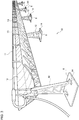
Fig. 3 is a schematic diagram illustrating a part of a first heat-collector. - Hereinafter, the same or equivalent constituent elements and members illustrated in the respective drawings will be denoted by the same reference numerals, and a redundant description thereof will be omitted as appropriate. In addition, dimensions of the members in the respective drawings are illustrated in an appropriately enlarged and reduced manner in order to facilitate understanding. In addition, some of the members which are not important for describing the embodiment are not displayed in the respective drawings.
-
Fig. 1 is a schematic diagram illustrating a solar heatpower generation system 100 according to an embodiment. The solar heatpower generation system 100 includes three areas of alight condensing area 121, aheat storage area 122, and apower generation area 123. - The
light condensing area 121 mainly includes a solarheat collecting device 8 and a heating system 2. The solarheat collecting device 8 collects sunlight and heats a heat transfer fluid flowing in a heat transfer fluid flow path (to be described later). The heated heat transfer fluid is sent to theheat storage area 122. The heating system 2 heats the heat transfer fluid flow path so as to prevent molten salt from solidifying by depriving heat from the heat transfer fluid flow path before pouring the molten salt into the heat transfer fluid flow path. - The
heat storage area 122 includes ahot tank 102 and acold tank 103. As the heat of the heated heat transfer fluid is stored in thehot tank 102, it is possible to generate power when necessary. For example, it is possible to generate power at night or in the bad weather in daytime. - The
power generation area 123 includes asteam generator 104, asteam turbine generator 106, and acondenser 108. Thesteam generator 104 generates steam using the heated heat transfer fluid stored in thehot tank 102, and thesteam turbine generator 106 rotates a turbine by the steam. Power is generated by this rotation. A relatively low-temperature heat transfer fluid whose heat is deprived by thesteam generator 104 is sent to thecold tank 103. Thecondenser 108 returns the steam to a liquid. -
Fig. 2 is a schematic diagram illustrating the solarheat collecting device 8. The solarheat collecting device 8 includes afirst light collector 10, asecond light collector 20, athird light collector 30, afourth light collector 40, aconnection pipeline 50, afirst cable 60, and asecond cable 62. - The
first light collector 10 includes a first heat transferfluid flow path 11, a plurality offirst supports 12, a plurality offirst reflectors 13, and afirst connection member 14.Fig. 3 is a schematic diagram illustrating a part of thefirst heat collector 10. Each of the plurality offirst supports 12 is formed using steel and erected on acradle 6 made of concrete. Thefirst support 12 is disposed along the first heat transferfluid flow path 11 and supports the first heat transferfluid flow path 11. In addition, thefirst support 12 rotatably supports thefirst reflector 13. - The
first reflector 13 collects the sunlight on the first heat transferfluid flow path 11 to heat the heat transfer fluid flowing inside the first heat transferfluid flow path 11. A rotating device (not illustrated) is connected to thefirst reflector 13. The rotating device rotates thefirst reflector 13 according to, for example, a position of the sun. As a result, the heat transfer fluid is efficiently heated. - The first heat transfer
fluid flow path 11 is made of metal, and the molten salt as the heat transfer fluid receiving solar heat flows therein. The molten salt has a boiling point higher than that of synthetic oil, conventionally used in solar heat collecting devices, and thus, can be warmed to higher temperature. As a result, the power generation efficiency by thesteam turbine generator 106 is improved. On the other hand, the molten salt solidifies at about 250°C. The molten salt basically does not solidify since being warmed by the solar heat at the time of collecting the light, but may solidify as the heat thereof is deprived by the first heat transferfluid flow path 11 when temperature of the first heat transferfluid flow path 11 is in a relatively low state before pouring the molten salt into the first heat transferfluid flow path 11, for example, at the time of start-up or after maintenance. Thus, it is necessary to warm the first heat transferfluid flow path 11 to predetermined temperature (for example, 280°C) or higher before pouring the molten salt into the first heat transferfluid flow path 11. - It is conceivable to warm the first heat transfer
fluid flow path 11 by laying a heating wire in the first heat transferfluid flow path 11 and causing a current to flow therethrough as a technique of warming the first heat transferfluid flow path 11. However, the first heat transferfluid flow path 11 is covered with a vacuum glass tube for heat insulation, and thus, it is difficult to lay the heating wire. Thus, one or a plurality of power sources (not illustrated) included in the heating system 2 are connected to the first heat transferfluid flow path 11 to cause a current to flow directly to the first heat transferfluid flow path 11, and the first heat transferfluid flow path 11 is warmed by Joule heat at that time in the present embodiment. Thus, the first heat transferfluid flow path 11 is insulated such that the current for warming the first heat transferfluid flow path 11 does not flow to thefirst support 12 that supports the first heat transferfluid flow path 11. In addition, thefirst support 12 is grounded as described below in preparation for insulation failure of the first heat transferfluid flow path 11 and the like. - Returning to
Fig. 2 , the first heat transferfluid flow path 11 is formed in a U shape and includes a longstraight line 11a and a longstraight line 11b extending in substantially the same direction. Thefirst support 12 and thefirst reflector 13 are disposed along these longstraight line 11a and longstraight line 11b. As an example, each of the longstraight line 11a and the longstraight line 11b has a length of 500 to 600 m and is supported by the tenfirst supports 12 in the illustrated example. - The plurality of
first supports 12 supporting the longstraight line 11a of the first heat transferfluid flow path 11 is electrically connected to each other by thefirst connection members 14 made of steel. Similarly, the plurality offirst supports 12 supporting the longstraight line 11b of the first heat transferfluid flow path 11 is electrically connected to each other by thefirst connection members 14. Some of thefirst connection member 14 are buried in the ground. That is, thefirst connection member 14 is connected to the ground. Thus, each of the first supports 12 is connected to the ground via thefirst connection member 14. As will be described later, only the first supports 12 which are not connected to thefirst cable 60 may be connected to the ground via thefirst connection member 14 while some of the plurality offirst supports 12 are connected to thefirst cable 60. - In addition, the first supports 12 supporting the long
straight line 11a of the first heat transferfluid flow path 11 and the first supports 12 supporting the longstraight line 11b of the first heat transferfluid flow path 11 are also connected to each other by thefirst connection members 14. In the present embodiment, the first supports 12 supporting the longstraight line 11a and the first supports 12 supporting the longstraight line 11b are connected to each other at a plurality of places (three places inFig. 2 ) by thefirst connection member 14. Thefirst connection member 14 is subjected to surface treatment such as galvanizing in order to prevent rusting or ignition caused by light collection. - The
second light collector 20 includes a second heat transferfluid flow path 21, a plurality ofsecond supports 22, a plurality ofsecond reflectors 23, and asecond connection member 24. - The third
light collector 30 includes a third heat transferfluid flow path 31, a plurality ofthird supports 32, a plurality ofthird reflectors 33, and athird connection member 34. - The fourth
light collector 40 includes a fourth heat transferfluid flow path 41, a plurality offourth supports 42, a plurality offourth reflectors 43, and afourth connection member 44. - Each of the second heat transfer
fluid flow path 21, the third heat transferfluid flow path 31, and the fourth heat transferfluid flow path 41 is configured in the same manner as the first heat transferfluid flow path 11. The second heat transferfluid flow path 21 is disposed such that a longstraight line 21a thereof is adjacent to the longstraight line 11b of the first heat transferfluid flow path 11 and extends in substantially the same direction. The fourth heat transferfluid flow path 41 is disposed such that a longstraight line 41a thereof is adjacent to a longstraight line 31b of the third heat transferfluid flow path 31 and extends in substantially the same direction. - Each of the
second support 22, thethird support 32, and thefourth support 42 is configured in the same manner as thefirst support 12. - Each of the
second reflector 23, thethird reflector 33, and thefourth reflector 43 is configured in the same manner as thefirst reflector 13. - Each of the
second connection member 24, thethird connection member 34, and thefourth connection member 44 is configured in the same manner as thefirst connection member 14. - The
connection pipeline 50 is an annular flow path and is connected to the first heat transferfluid flow path 11, the second heat transferfluid flow path 21, the third heat transferfluid flow path 31, and the fourth heat transferfluid flow path 41. In addition, theconnection pipeline 50 is also connected to thehot tank 102 and thecold tank 103 of theheat storage area 122. Therefore, the first heat transferfluid flow path 11, the second heat transferfluid flow path 21, the third heat transferfluid flow path 31, the fourth heat transferfluid flow path 41, thehot tank 102, and thecold tank 103 are connected via theconnection pipeline 50. The heat transfer fluid heated in each heat transfer fluid flow path is sent to thehot tank 102 via theconnection pipeline 50. In addition, the relatively low-temperature heat transfer fluid stored in thecold tank 103 is sent to each heat transfer fluid flow path via theconnection pipeline 50. - The
first cable 60 is provided between thefirst light collector 10 and thesecond light collector 20. Thefirst cable 60 is a copper cable for grounding, and one end of thefirst cable 60 is connected to a main earth grid which is an earth grid of the entire solar heatpower generation system 100. Some (three inFig. 2 ) of the first supports 12 among the plurality offirst supports 12 supporting the first heat transferfluid flow path 11 are grounded by thefirst cable 60. That is, some of the first supports 12 are grounded by a cable having a relatively high conductivity (in particular, higher than that of the first connection member 14). In addition, the first supports 12 to which thefirst cable 60 is not connected are also electrically connected to thefirst cable 60 via thefirst connection members 14 and the otherfirst supports 12 since the respectivefirst supports 12 are electrically connected to each other by thefirst connection members 14 as described above. Since the first heat transferfluid flow path 11 is formed in the U shape, and the first supports 12 supporting the longstraight line 11a and the first supports 12 supporting the longstraight line 11b are connected at the plurality of places by thefirst connection members 14 in the present embodiment, each of the first supports 12 is electrically connected to thefirst cable 60 through a plurality of paths. - Since the
first cable 60 is made of copper and thefirst support 12 is made of steel, thefirst cable 60 and thefirst support 12 are joined by a dissimilarmetal joining member 64. As a result, it is possible to prevent corrosion caused by contact between copper and steel (that is, contact between dissimilar metals). A ratio of the number of the first supports 12 connected to thefirst cable 60 relative to the total number of the first supports 12 is desirably 1/10 to 3/10. If the ratio is lower than this, the number of paths that electrically connects the respectivefirst supports 12 and thefirst cable 60 is reduced, and thus, there is a risk that the electrical safety of the solarheat collecting device 8 as a whole may fall below the standard. In addition, if the ratio is higher than this, material cost of the dissimilarmetal joining member 64 and the time and effort for construction increase, which is uneconomical. - In addition, some (the three
second supports 22 inFig. 2 ) of the second supports 22 among the plurality ofsecond supports 22 that supports the second heat transferfluid flow path 21 are grounded by thefirst cable 60. That is, thefirst light collector 10 and thesecond light collector 20 are grounded by the commonfirst cable 60 provided therebetween. - The
second cable 62 is provided between the thirdlight collector 30 and the fourthlight collector 40. Thesecond cable 62 is a copper cable for grounding and is connected to the main earth grid, which is similar to thefirst cable 60. Some (three inFig. 2 ) of the third supports 32 among the plurality ofthird supports 32 and some (three inFig. 2 ) of the fourth supports 42 among the plurality offourth supports 42 are grounded by thesecond cable 62. That is, the thirdlight collector 30 and the fourthlight collector 40 are grounded by the commonsecond cable 62 provided therebetween. - Some supports of each of the light collectors are connected to the copper cable by a dissimilar
metal joining member 64 according to the solarheat collecting device 8 according to the above-described embodiment. Here, since each of the light collectors has a lot of supports, it takes time and effort to complete the construction and the material cost of the dissimilarmetal joining member 64 increases if all these supports are connected to the copper cable by the dissimilarmetal joining member 64. In regard to this, only some (for example, 1/10 to 3/10 out of the plurality of supports) of the supports are connected to the copper cable by the dissimilarmetal joining member 64 as described above according to the solarheat collecting device 8 according to the embodiment, and thus, it is possible to suppress the time and effort for construction and the material cost of the dissimilarmetal joining member 64 as compared with the case where all the supports are connected to the cable via the dissimilarmetal joining member 64. - In addition, the respective supports of the respective light collector are connected to the ground (that is, grounded) by the connection member made of steel according to the solar
heat collecting device 8 according to the present embodiment. In addition, there is a risk that electricity may be accumulated in the support when insulation failure occurs in the heat transfer fluid flow path in a large-scale structure with a large number of supports such as the solarheat collecting device 8 of the embodiment even if a ground standard of the solarheat collecting device 8 as a whole is satisfied by grounding some of the first supports 12 via the cable. In regard to this, since the respective supports are also grounded by the connection members as described above according to the solarheat collecting device 8 of the embodiment, the electricity is not accumulated in the support even if the insulation failure occurs in the heat transfer fluid flow path. That is, it is possible to secure the electrical safety while reducing the cable to the minimum and suppressing the time and effort required for joining using the dissimilarmetal joining member 64 according to the solarheat collecting device 8. - In addition, there is a case where light is unintentionally collected in the cable so that temperature of the cable increases depending on an angle of the reflector. The cable is made of copper and deforms and corrodes at relatively low temperature. In regard to this, it is possible to reduce the copper cable while securing the electrical safety using the connection member made of steel that is unlikely to cause such problems, in the present embodiment. Thus, a maintenance frequency of the copper cable is reduced, and maintenance cost is reduced.
- According to the solar
heat collecting device 8 of the present embodiment, each of the supports is electrically connected to the copper cable through the plurality of paths by the connection members. Thus, the electrical safety is maintained even when some of the path are broken due to breakage of the connection member. - According to the solar
heat collecting device 8 of the present embodiment, thefirst light collector 10 and thesecond light collector 20 are grounded by the common copper cable provided therebetween. Therefore, the material cost is reduced since the number of cables is reduced as compared with the case of being grounded by different cables. - As above, the present invention has been described based on the embodiment. This embodiment is illustrative, and it is understood by those skilled in the art that various types of modification examples can be made in combinations of the respective components and the respective processes, and further, such modification examples are included in a range of the invention.
- Although the case where the solar
heat collecting device 8 includes the four light collectors has been described in the embodiment, the present invention is not limited thereto. The solarheat collecting device 8 may include one, two, three, or five or more light collectors. - Although the case where all the supports are connected to each other via the connection member in each light collector has been described in the embodiment, the present invention is not limited thereto. Each support may be connected to a cable directly or via another support and a connection member, and it is unnecessary for all the supports in each light collector to be connected to each other by the connection member.
- Although the description has been given in the embodiment regarding the case where each of the supports is grounded by the cable directly or via another support and the connection member and grounded (connected to the ground) by the connection member, the present invention is not limited thereto. There may be a support that is grounded by a cable but is not grounded by a connection member, and there may be a support that is grounded by the connection member but is not grounded by the cable. In addition, there may be a support that is not grounded by either the cable or the connection member.
- Although the case where the support and the connection member are made of steel and the
first cable 60 and thesecond cable 62 are made of copper has been described in the embodiment, the present invention is not limited thereto. A support may be formed using another conductive material that requires a dissimilar material joining member for connection with thefirst cable 60 and thesecond cable 62. A connection member may be formed using the same conductive material as the support. In addition, thefirst cable 60 and thesecond cable 62 may be formed using a conductive material which requires a dissimilar material joining member for connection with the support and has higher conductivity than the support. - Although the case where the single grounding cable is provided for the two light collectors has been described in the embodiment, the present invention is not limited thereto. One grounding cable may be provided for one light collector, or one grounding cable may be provided for three or more light collectors.
- 8 solar heat collecting device, 10 first light collector, 11 first heat transfer fluid flow path, 12 first support, 14 first connection member, 20 second light collector, 21 second heat transfer fluid flow path, 22 second support, 24 second connection member, 30 third light collector, 31 third heat transfer fluid flow path, 32 third support, 34 third connection member, 40 fourth light collector, 41 fourth heat transfer fluid flow path, 42 fourth support, 44 fourth connection member, 60 first cable, 62 second cable, 100 solar heat power generation system, 104 steam generator, 106 steam turbine generator.
- The present invention can be applied to a solar heat collecting device and a solar heat power generation system.
Claims (5)
- A ground structure of a solar heat collecting device comprising:a first heat transfer fluid flow path through which a heat transfer fluid receiving solar heat flows; anda plurality of first supports formed using a first conductive material that supports the first heat transfer fluid flow path,wherein the first heat transfer fluid flow path is warmed by being energized,some of the first supports among the plurality of first supports are grounded via a cable, which is connected to the some first supports via a dissimilar material joining member and formed using a second conductive material,at least some other first supports among the plurality of first supports are connected to the ground via a connection member formed using the first conductive material, andthe second conductive material has higher conductivity than the first conductive material.
- A ground structure of a solar heat collecting device comprising:a first heat transfer fluid flow path through which a heat transfer fluid receiving solar heat flows; anda plurality of first supports which is made of steel and supports the first heat transfer fluid flow path,wherein the first heat transfer fluid flow path is warmed by being energized,some of the first supports among the plurality of first supports are grounded via a cable made of copper, andat least some other first supports among the plurality of first supports are connected to the ground via a connection member made of steel.
- The ground structure of a solar heat collecting device according to claim 1 or 2, wherein
the at least some other first supports are connected to the some first supports via the connection member. - The ground structure of a solar heat collecting device according to any one of claims 1 to 35, further comprising:a second heat transfer fluid flow path through which a heat transfer fluid receiving solar heat flows; anda plurality of second supports that supports the second heat transfer fluid flow path,wherein the plurality of second supports is grounded via the cable grounding the some first supports that support the first heat transfer fluid flow path.
- A solar heat collecting device comprising the ground structure of a solar heat collecting device according to any one of claims 1 to 46.
Applications Claiming Priority (1)
| Application Number | Priority Date | Filing Date | Title |
|---|---|---|---|
| PCT/JP2015/069147 WO2017002259A1 (en) | 2015-07-02 | 2015-07-02 | Solar thermal collector grounding structure, solar thermal collector and solar thermal generator system |
Publications (3)
| Publication Number | Publication Date |
|---|---|
| EP3318815A1 true EP3318815A1 (en) | 2018-05-09 |
| EP3318815A4 EP3318815A4 (en) | 2018-11-14 |
| EP3318815B1 EP3318815B1 (en) | 2020-04-15 |
Family
ID=57609411
Family Applications (1)
| Application Number | Title | Priority Date | Filing Date |
|---|---|---|---|
| EP15897186.1A Active EP3318815B1 (en) | 2015-07-02 | 2015-07-02 | Solar thermal collector grounding structure and solar thermal collector |
Country Status (8)
| Country | Link |
|---|---|
| EP (1) | EP3318815B1 (en) |
| JP (1) | JP6543708B2 (en) |
| CN (1) | CN107709891B (en) |
| ES (1) | ES2806149T3 (en) |
| MA (1) | MA42283B1 (en) |
| PT (1) | PT3318815T (en) |
| SA (1) | SA518390671B1 (en) |
| WO (1) | WO2017002259A1 (en) |
Family Cites Families (11)
| Publication number | Priority date | Publication date | Assignee | Title |
|---|---|---|---|---|
| NL7808774A (en) * | 1978-08-25 | 1980-02-27 | Philips Nv | SOLAR COLLECTOR. |
| DE102008037711A1 (en) * | 2008-08-14 | 2010-02-18 | Senior Berghöfer GmbH | Connection system for a pipe of a solar thermal system that can be swiveled about a rotation axis |
| US8925543B2 (en) * | 2009-01-13 | 2015-01-06 | Aerojet Rocketdyne Of De, Inc. | Catalyzed hot gas heating system for pipes |
| MA34164B1 (en) * | 2010-04-22 | 2013-04-03 | Trevor Powell | SOLAR ENERGY COLLECTION SYSTEM |
| PT2710288E (en) * | 2011-05-19 | 2015-10-02 | Basf Se | Pipeline for conveying a salt melt |
| CN103857906B (en) * | 2011-09-06 | 2016-12-21 | 巴斯夫欧洲公司 | Pipe system and method for emptying the pipe system |
| ES2500865B1 (en) * | 2011-10-20 | 2015-07-20 | Abengoa Solar Llc | Heating system of a heat transfer fluid for a parabolic trough solar concentrator |
| JP2014102013A (en) * | 2012-11-16 | 2014-06-05 | Chiyoda Corp | Light condensing device for solar power generation |
| JP2014159892A (en) * | 2013-02-19 | 2014-09-04 | Toshiba Corp | Solar heat collection device and solar heat power generation system |
| CN103712358B (en) * | 2013-12-30 | 2015-10-14 | 北京工业大学 | A kind of slot type vacuum heat collection pipe D.C. high-current fused salt thaws preheating device |
| CN203731722U (en) * | 2013-12-30 | 2014-07-23 | 北京工业大学 | D.C. high-current molten salt unfreezing and preheating device via groove type vacuum heat collecting pipes |
-
2015
- 2015-07-02 JP JP2017525771A patent/JP6543708B2/en not_active Expired - Fee Related
- 2015-07-02 WO PCT/JP2015/069147 patent/WO2017002259A1/en not_active Ceased
- 2015-07-02 MA MA42283A patent/MA42283B1/en unknown
- 2015-07-02 EP EP15897186.1A patent/EP3318815B1/en active Active
- 2015-07-02 ES ES15897186T patent/ES2806149T3/en active Active
- 2015-07-02 CN CN201580081409.3A patent/CN107709891B/en not_active Expired - Fee Related
- 2015-07-02 PT PT158971861T patent/PT3318815T/en unknown
-
2018
- 2018-01-01 SA SA518390671A patent/SA518390671B1/en unknown
Also Published As
| Publication number | Publication date |
|---|---|
| CN107709891B (en) | 2020-01-10 |
| SA518390671B1 (en) | 2021-07-26 |
| MA42283B1 (en) | 2020-07-29 |
| EP3318815A4 (en) | 2018-11-14 |
| ES2806149T3 (en) | 2021-02-16 |
| JPWO2017002259A1 (en) | 2018-03-29 |
| EP3318815B1 (en) | 2020-04-15 |
| CN107709891A (en) | 2018-02-16 |
| PT3318815T (en) | 2020-07-16 |
| WO2017002259A1 (en) | 2017-01-05 |
| JP6543708B2 (en) | 2019-07-10 |
| MA42283A (en) | 2020-04-15 |
Similar Documents
| Publication | Publication Date | Title |
|---|---|---|
| US9631839B2 (en) | Heat transfer fluid heating system and method for a parabolic trough solar concentrator | |
| JP4477057B2 (en) | Beam-down solar power generator | |
| US20150377221A1 (en) | Integrated thermal storage, heat exchange, and steam generation | |
| RU2550073C2 (en) | Device for thermoelectric protection of pipeline from corrosion | |
| EP3318815B1 (en) | Solar thermal collector grounding structure and solar thermal collector | |
| EP4381239B1 (en) | Energy storage device and method of heating a heat transfer fluid | |
| EP3318818B1 (en) | Solar heat collector | |
| JP6543710B2 (en) | Heating device | |
| KR101463861B1 (en) | Solar water heater having multiple hot-water generating function | |
| CN107709892B (en) | Heating system | |
| WO2017002262A1 (en) | Heater | |
| Roman et al. | An overview on solar energy, molten salts and electromagnetic pumping technologies | |
| JPWO2017002252A1 (en) | Solar heat collector | |
| RU2610164C1 (en) | Themal wind-driven power plant | |
| WO2016189702A1 (en) | Solar heat collection device, preheating method of heat collection tube, and heat medium introduction method | |
| JP3084097U (en) | Snow melting unit | |
| JP2009002637A (en) | Hybrid heat transfer device | |
| EP3306224A1 (en) | Solar heat collection device and preheating method of heat collection tube | |
| Şengüler et al. | Hybrid Solar And Wind Energy Potential Map of Turkey and Cost Analysis of 1 MW Hybrid Power Plants | |
| JP2014150147A (en) | Solar power generation system | |
| KR20110105042A (en) | Used hot water generator using solar heat | |
| SI23624A (en) | Procedure of heating sanitary water and/or spaces |
Legal Events
| Date | Code | Title | Description |
|---|---|---|---|
| STAA | Information on the status of an ep patent application or granted ep patent |
Free format text: STATUS: THE INTERNATIONAL PUBLICATION HAS BEEN MADE |
|
| PUAI | Public reference made under article 153(3) epc to a published international application that has entered the european phase |
Free format text: ORIGINAL CODE: 0009012 |
|
| STAA | Information on the status of an ep patent application or granted ep patent |
Free format text: STATUS: REQUEST FOR EXAMINATION WAS MADE |
|
| 17P | Request for examination filed |
Effective date: 20180131 |
|
| AK | Designated contracting states |
Kind code of ref document: A1 Designated state(s): AL AT BE BG CH CY CZ DE DK EE ES FI FR GB GR HR HU IE IS IT LI LT LU LV MC MK MT NL NO PL PT RO RS SE SI SK SM TR |
|
| AX | Request for extension of the european patent |
Extension state: BA ME |
|
| DAX | Request for extension of the european patent (deleted) | ||
| REG | Reference to a national code |
Ref country code: DE Ref legal event code: R079 Ref document number: 602015050936 Country of ref document: DE Free format text: PREVIOUS MAIN CLASS: F24J0002240000 Ipc: F16L0053000000 |
|
| A4 | Supplementary search report drawn up and despatched |
Effective date: 20181016 |
|
| RIC1 | Information provided on ipc code assigned before grant |
Ipc: H01R 4/64 20060101ALI20181010BHEP Ipc: F16L 53/00 20180101AFI20181010BHEP Ipc: F24S 10/70 20180101ALI20181010BHEP Ipc: F24S 50/00 20180101ALI20181010BHEP |
|
| STAA | Information on the status of an ep patent application or granted ep patent |
Free format text: STATUS: EXAMINATION IS IN PROGRESS |
|
| 17Q | First examination report despatched |
Effective date: 20190606 |
|
| GRAP | Despatch of communication of intention to grant a patent |
Free format text: ORIGINAL CODE: EPIDOSNIGR1 |
|
| STAA | Information on the status of an ep patent application or granted ep patent |
Free format text: STATUS: GRANT OF PATENT IS INTENDED |
|
| INTG | Intention to grant announced |
Effective date: 20200109 |
|
| GRAS | Grant fee paid |
Free format text: ORIGINAL CODE: EPIDOSNIGR3 |
|
| GRAA | (expected) grant |
Free format text: ORIGINAL CODE: 0009210 |
|
| STAA | Information on the status of an ep patent application or granted ep patent |
Free format text: STATUS: THE PATENT HAS BEEN GRANTED |
|
| AK | Designated contracting states |
Kind code of ref document: B1 Designated state(s): AL AT BE BG CH CY CZ DE DK EE ES FI FR GB GR HR HU IE IS IT LI LT LU LV MC MK MT NL NO PL PT RO RS SE SI SK SM TR |
|
| REG | Reference to a national code |
Ref country code: CH Ref legal event code: EP |
|
| REG | Reference to a national code |
Ref country code: DE Ref legal event code: R096 Ref document number: 602015050936 Country of ref document: DE |
|
| REG | Reference to a national code |
Ref country code: IE Ref legal event code: FG4D |
|
| REG | Reference to a national code |
Ref country code: AT Ref legal event code: REF Ref document number: 1257719 Country of ref document: AT Kind code of ref document: T Effective date: 20200515 |
|
| REG | Reference to a national code |
Ref country code: PT Ref legal event code: SC4A Ref document number: 3318815 Country of ref document: PT Date of ref document: 20200716 Kind code of ref document: T Free format text: AVAILABILITY OF NATIONAL TRANSLATION Effective date: 20200713 |
|
| REG | Reference to a national code |
Ref country code: MA Ref legal event code: VAGR Ref document number: 42283 Country of ref document: MA Kind code of ref document: B1 |
|
| REG | Reference to a national code |
Ref country code: NL Ref legal event code: MP Effective date: 20200415 |
|
| REG | Reference to a national code |
Ref country code: LT Ref legal event code: MG4D |
|
| PG25 | Lapsed in a contracting state [announced via postgrant information from national office to epo] |
Ref country code: GR Free format text: LAPSE BECAUSE OF FAILURE TO SUBMIT A TRANSLATION OF THE DESCRIPTION OR TO PAY THE FEE WITHIN THE PRESCRIBED TIME-LIMIT Effective date: 20200716 Ref country code: FI Free format text: LAPSE BECAUSE OF FAILURE TO SUBMIT A TRANSLATION OF THE DESCRIPTION OR TO PAY THE FEE WITHIN THE PRESCRIBED TIME-LIMIT Effective date: 20200415 Ref country code: LT Free format text: LAPSE BECAUSE OF FAILURE TO SUBMIT A TRANSLATION OF THE DESCRIPTION OR TO PAY THE FEE WITHIN THE PRESCRIBED TIME-LIMIT Effective date: 20200415 Ref country code: NL Free format text: LAPSE BECAUSE OF FAILURE TO SUBMIT A TRANSLATION OF THE DESCRIPTION OR TO PAY THE FEE WITHIN THE PRESCRIBED TIME-LIMIT Effective date: 20200415 Ref country code: NO Free format text: LAPSE BECAUSE OF FAILURE TO SUBMIT A TRANSLATION OF THE DESCRIPTION OR TO PAY THE FEE WITHIN THE PRESCRIBED TIME-LIMIT Effective date: 20200715 Ref country code: SE Free format text: LAPSE BECAUSE OF FAILURE TO SUBMIT A TRANSLATION OF THE DESCRIPTION OR TO PAY THE FEE WITHIN THE PRESCRIBED TIME-LIMIT Effective date: 20200415 Ref country code: IS Free format text: LAPSE BECAUSE OF FAILURE TO SUBMIT A TRANSLATION OF THE DESCRIPTION OR TO PAY THE FEE WITHIN THE PRESCRIBED TIME-LIMIT Effective date: 20200815 |
|
| REG | Reference to a national code |
Ref country code: AT Ref legal event code: MK05 Ref document number: 1257719 Country of ref document: AT Kind code of ref document: T Effective date: 20200415 |
|
| PG25 | Lapsed in a contracting state [announced via postgrant information from national office to epo] |
Ref country code: BG Free format text: LAPSE BECAUSE OF FAILURE TO SUBMIT A TRANSLATION OF THE DESCRIPTION OR TO PAY THE FEE WITHIN THE PRESCRIBED TIME-LIMIT Effective date: 20200715 Ref country code: HR Free format text: LAPSE BECAUSE OF FAILURE TO SUBMIT A TRANSLATION OF THE DESCRIPTION OR TO PAY THE FEE WITHIN THE PRESCRIBED TIME-LIMIT Effective date: 20200415 Ref country code: RS Free format text: LAPSE BECAUSE OF FAILURE TO SUBMIT A TRANSLATION OF THE DESCRIPTION OR TO PAY THE FEE WITHIN THE PRESCRIBED TIME-LIMIT Effective date: 20200415 Ref country code: LV Free format text: LAPSE BECAUSE OF FAILURE TO SUBMIT A TRANSLATION OF THE DESCRIPTION OR TO PAY THE FEE WITHIN THE PRESCRIBED TIME-LIMIT Effective date: 20200415 |
|
| PG25 | Lapsed in a contracting state [announced via postgrant information from national office to epo] |
Ref country code: AL Free format text: LAPSE BECAUSE OF FAILURE TO SUBMIT A TRANSLATION OF THE DESCRIPTION OR TO PAY THE FEE WITHIN THE PRESCRIBED TIME-LIMIT Effective date: 20200415 |
|
| REG | Reference to a national code |
Ref country code: DE Ref legal event code: R097 Ref document number: 602015050936 Country of ref document: DE |
|
| PG25 | Lapsed in a contracting state [announced via postgrant information from national office to epo] |
Ref country code: AT Free format text: LAPSE BECAUSE OF FAILURE TO SUBMIT A TRANSLATION OF THE DESCRIPTION OR TO PAY THE FEE WITHIN THE PRESCRIBED TIME-LIMIT Effective date: 20200415 Ref country code: RO Free format text: LAPSE BECAUSE OF FAILURE TO SUBMIT A TRANSLATION OF THE DESCRIPTION OR TO PAY THE FEE WITHIN THE PRESCRIBED TIME-LIMIT Effective date: 20200415 Ref country code: CZ Free format text: LAPSE BECAUSE OF FAILURE TO SUBMIT A TRANSLATION OF THE DESCRIPTION OR TO PAY THE FEE WITHIN THE PRESCRIBED TIME-LIMIT Effective date: 20200415 Ref country code: EE Free format text: LAPSE BECAUSE OF FAILURE TO SUBMIT A TRANSLATION OF THE DESCRIPTION OR TO PAY THE FEE WITHIN THE PRESCRIBED TIME-LIMIT Effective date: 20200415 Ref country code: SM Free format text: LAPSE BECAUSE OF FAILURE TO SUBMIT A TRANSLATION OF THE DESCRIPTION OR TO PAY THE FEE WITHIN THE PRESCRIBED TIME-LIMIT Effective date: 20200415 Ref country code: DK Free format text: LAPSE BECAUSE OF FAILURE TO SUBMIT A TRANSLATION OF THE DESCRIPTION OR TO PAY THE FEE WITHIN THE PRESCRIBED TIME-LIMIT Effective date: 20200415 |
|
| REG | Reference to a national code |
Ref country code: DE Ref legal event code: R119 Ref document number: 602015050936 Country of ref document: DE |
|
| REG | Reference to a national code |
Ref country code: ES Ref legal event code: FG2A Ref document number: 2806149 Country of ref document: ES Kind code of ref document: T3 Effective date: 20210216 |
|
| PLBE | No opposition filed within time limit |
Free format text: ORIGINAL CODE: 0009261 |
|
| STAA | Information on the status of an ep patent application or granted ep patent |
Free format text: STATUS: NO OPPOSITION FILED WITHIN TIME LIMIT |
|
| PG25 | Lapsed in a contracting state [announced via postgrant information from national office to epo] |
Ref country code: MC Free format text: LAPSE BECAUSE OF FAILURE TO SUBMIT A TRANSLATION OF THE DESCRIPTION OR TO PAY THE FEE WITHIN THE PRESCRIBED TIME-LIMIT Effective date: 20200415 Ref country code: SK Free format text: LAPSE BECAUSE OF FAILURE TO SUBMIT A TRANSLATION OF THE DESCRIPTION OR TO PAY THE FEE WITHIN THE PRESCRIBED TIME-LIMIT Effective date: 20200415 Ref country code: PL Free format text: LAPSE BECAUSE OF FAILURE TO SUBMIT A TRANSLATION OF THE DESCRIPTION OR TO PAY THE FEE WITHIN THE PRESCRIBED TIME-LIMIT Effective date: 20200415 |
|
| REG | Reference to a national code |
Ref country code: CH Ref legal event code: PL |
|
| 26N | No opposition filed |
Effective date: 20210118 |
|
| GBPC | Gb: european patent ceased through non-payment of renewal fee |
Effective date: 20200715 |
|
| REG | Reference to a national code |
Ref country code: BE Ref legal event code: MM Effective date: 20200731 |
|
| PG25 | Lapsed in a contracting state [announced via postgrant information from national office to epo] |
Ref country code: IE Free format text: LAPSE BECAUSE OF NON-PAYMENT OF DUE FEES Effective date: 20200702 Ref country code: GB Free format text: LAPSE BECAUSE OF NON-PAYMENT OF DUE FEES Effective date: 20200715 Ref country code: CH Free format text: LAPSE BECAUSE OF NON-PAYMENT OF DUE FEES Effective date: 20200731 Ref country code: LI Free format text: LAPSE BECAUSE OF NON-PAYMENT OF DUE FEES Effective date: 20200731 Ref country code: LU Free format text: LAPSE BECAUSE OF NON-PAYMENT OF DUE FEES Effective date: 20200702 Ref country code: FR Free format text: LAPSE BECAUSE OF NON-PAYMENT OF DUE FEES Effective date: 20200731 |
|
| PG25 | Lapsed in a contracting state [announced via postgrant information from national office to epo] |
Ref country code: SI Free format text: LAPSE BECAUSE OF FAILURE TO SUBMIT A TRANSLATION OF THE DESCRIPTION OR TO PAY THE FEE WITHIN THE PRESCRIBED TIME-LIMIT Effective date: 20200415 Ref country code: BE Free format text: LAPSE BECAUSE OF NON-PAYMENT OF DUE FEES Effective date: 20200731 Ref country code: DE Free format text: LAPSE BECAUSE OF NON-PAYMENT OF DUE FEES Effective date: 20210202 |
|
| VSFP | Annual fee paid to validation state [announced via postgrant information from national office to epo] |
Ref country code: MA Payment date: 20200803 Year of fee payment: 6 |
|
| PGFP | Annual fee paid to national office [announced via postgrant information from national office to epo] |
Ref country code: IT Payment date: 20210610 Year of fee payment: 7 |
|
| PGFP | Annual fee paid to national office [announced via postgrant information from national office to epo] |
Ref country code: ES Payment date: 20210805 Year of fee payment: 7 |
|
| PGFP | Annual fee paid to national office [announced via postgrant information from national office to epo] |
Ref country code: PT Payment date: 20210702 Year of fee payment: 7 |
|
| PG25 | Lapsed in a contracting state [announced via postgrant information from national office to epo] |
Ref country code: TR Free format text: LAPSE BECAUSE OF FAILURE TO SUBMIT A TRANSLATION OF THE DESCRIPTION OR TO PAY THE FEE WITHIN THE PRESCRIBED TIME-LIMIT Effective date: 20200415 Ref country code: MT Free format text: LAPSE BECAUSE OF FAILURE TO SUBMIT A TRANSLATION OF THE DESCRIPTION OR TO PAY THE FEE WITHIN THE PRESCRIBED TIME-LIMIT Effective date: 20200415 Ref country code: CY Free format text: LAPSE BECAUSE OF FAILURE TO SUBMIT A TRANSLATION OF THE DESCRIPTION OR TO PAY THE FEE WITHIN THE PRESCRIBED TIME-LIMIT Effective date: 20200415 |
|
| PG25 | Lapsed in a contracting state [announced via postgrant information from national office to epo] |
Ref country code: MK Free format text: LAPSE BECAUSE OF FAILURE TO SUBMIT A TRANSLATION OF THE DESCRIPTION OR TO PAY THE FEE WITHIN THE PRESCRIBED TIME-LIMIT Effective date: 20200415 |
|
| PG25 | Lapsed in a contracting state [announced via postgrant information from national office to epo] |
Ref country code: PT Free format text: LAPSE BECAUSE OF NON-PAYMENT OF DUE FEES Effective date: 20230102 |
|
| PG25 | Lapsed in a contracting state [announced via postgrant information from national office to epo] |
Ref country code: IT Free format text: LAPSE BECAUSE OF NON-PAYMENT OF DUE FEES Effective date: 20220702 |
|
| REG | Reference to a national code |
Ref country code: ES Ref legal event code: FD2A Effective date: 20230825 |
|
| PG25 | Lapsed in a contracting state [announced via postgrant information from national office to epo] |
Ref country code: ES Free format text: LAPSE BECAUSE OF NON-PAYMENT OF DUE FEES Effective date: 20220703 |
|
| VS25 | Lapsed in a validation state [announced via postgrant information from nat. office to epo] |
Ref country code: MA Free format text: LAPSE BECAUSE OF NON-PAYMENT OF DUE FEES Effective date: 20220703 |
|
| VSFP | Annual fee paid to validation state [announced via postgrant information from national office to epo] |
Ref country code: MA Payment date: 20210622 Year of fee payment: 7 |
|
| VSFP | Annual fee paid to validation state [announced via postgrant information from national office to epo] |
Ref country code: MA Payment date: 20200728 Year of fee payment: 6 Ref country code: MA Payment date: 20200803 Year of fee payment: 5 |