EP3318731A1 - Flow guide structure for casing flange, and casing and turbomachine having the same - Google Patents
Flow guide structure for casing flange, and casing and turbomachine having the same Download PDFInfo
- Publication number
- EP3318731A1 EP3318731A1 EP17200042.4A EP17200042A EP3318731A1 EP 3318731 A1 EP3318731 A1 EP 3318731A1 EP 17200042 A EP17200042 A EP 17200042A EP 3318731 A1 EP3318731 A1 EP 3318731A1
- Authority
- EP
- European Patent Office
- Prior art keywords
- casing
- flow guide
- flow
- guide means
- inclined portion
- Prior art date
- Legal status (The legal status is an assumption and is not a legal conclusion. Google has not performed a legal analysis and makes no representation as to the accuracy of the status listed.)
- Granted
Links
Images










Classifications
-
- F—MECHANICAL ENGINEERING; LIGHTING; HEATING; WEAPONS; BLASTING
- F01—MACHINES OR ENGINES IN GENERAL; ENGINE PLANTS IN GENERAL; STEAM ENGINES
- F01D—NON-POSITIVE DISPLACEMENT MACHINES OR ENGINES, e.g. STEAM TURBINES
- F01D25/00—Component parts, details, or accessories, not provided for in, or of interest apart from, other groups
- F01D25/24—Casings; Casing parts, e.g. diaphragms, casing fastenings
-
- F—MECHANICAL ENGINEERING; LIGHTING; HEATING; WEAPONS; BLASTING
- F01—MACHINES OR ENGINES IN GENERAL; ENGINE PLANTS IN GENERAL; STEAM ENGINES
- F01D—NON-POSITIVE DISPLACEMENT MACHINES OR ENGINES, e.g. STEAM TURBINES
- F01D25/00—Component parts, details, or accessories, not provided for in, or of interest apart from, other groups
- F01D25/24—Casings; Casing parts, e.g. diaphragms, casing fastenings
- F01D25/243—Flange connections; Bolting arrangements
-
- F—MECHANICAL ENGINEERING; LIGHTING; HEATING; WEAPONS; BLASTING
- F01—MACHINES OR ENGINES IN GENERAL; ENGINE PLANTS IN GENERAL; STEAM ENGINES
- F01D—NON-POSITIVE DISPLACEMENT MACHINES OR ENGINES, e.g. STEAM TURBINES
- F01D25/00—Component parts, details, or accessories, not provided for in, or of interest apart from, other groups
- F01D25/28—Supporting or mounting arrangements, e.g. for turbine casing
-
- F—MECHANICAL ENGINEERING; LIGHTING; HEATING; WEAPONS; BLASTING
- F01—MACHINES OR ENGINES IN GENERAL; ENGINE PLANTS IN GENERAL; STEAM ENGINES
- F01D—NON-POSITIVE DISPLACEMENT MACHINES OR ENGINES, e.g. STEAM TURBINES
- F01D9/00—Stators
- F01D9/02—Nozzles; Nozzle boxes; Stator blades; Guide conduits, e.g. individual nozzles
- F01D9/04—Nozzles; Nozzle boxes; Stator blades; Guide conduits, e.g. individual nozzles forming ring or sector
- F01D9/041—Nozzles; Nozzle boxes; Stator blades; Guide conduits, e.g. individual nozzles forming ring or sector using blades
-
- F—MECHANICAL ENGINEERING; LIGHTING; HEATING; WEAPONS; BLASTING
- F05—INDEXING SCHEMES RELATING TO ENGINES OR PUMPS IN VARIOUS SUBCLASSES OF CLASSES F01-F04
- F05D—INDEXING SCHEME FOR ASPECTS RELATING TO NON-POSITIVE-DISPLACEMENT MACHINES OR ENGINES, GAS-TURBINES OR JET-PROPULSION PLANTS
- F05D2260/00—Function
- F05D2260/97—Reducing windage losses
Definitions
- Exemplary embodiments of the present invention relate to a flow guide structure for a casing flange, and a casing and a turbomachine having the same, and more particularly, to a structure reducing steam flow resistance around a casing flange and smoothing steam flow.
- a turbomachine is a power generation apparatus converting a thermal energy of fluid, such as gas, steam and the like into a rotating force being a mechanical energy, and comprises a rotor having a plurality of buckets to perform shaft rotation by the fluid and a casing installed to surround the rotor and having a plurality of diaphragms.
- a gas turbine includes a compressor section, a combustor, and a turbine section; an external air is inhaled and compressed by rotation of the compressor section and then sent to the combustor, and burnt by a mixture of the compressed air and fuel in the combustor.
- a high temperature/high pressure of gas generated in the combustor rotates the rotor of the turbine while passing through the turbine section, and thus operates a generator.
- a steam turbine In a steam turbine, it serially or in parallel connects a high-pressure turbine section, an intermediate-pressure turbine section, and a low-pressure turbine section and rotates a rotor; in the serially connected structure, the high-pressure turbine section, the medium-pressure turbine section, and the low-pressure turbine section share one rotor.
- Each of turbines in the steam turbine includes a bucket and a diaphragm around a rotor inside a casing, and steam rotates the rotor while passing through the bucket and the diaphragm, and thus operates a generator.
- FIG. 1 an inner casing of a low-pressure turbine inside a steam turbine is shown.
- Power steam passes through a high-pressure turbine, an intermediate-pressure turbine, and a low-pressure turbine in order, and then finally flows toward a condenser positioned at a lower end portion of the low-pressure turbine. Accordingly, the power steam discharged through a diaphragm 2 of the low-pressure turbine moves in a direction of the lower end of the low-pressure turbine.
- the inner casing has a structure with an upper casing 3 and a lower casing 4 coupled by flanges 5a, 5b, respectively, and almost has a stepped shape in a direction of an outer side thereof.
- Patent Document 1 US Patent No. 635204
- the present invention is proposed for resolving the above problems of a conventional technology, and the object of the present invention is to provide a structure reducing steam flow resistance around a casing flange and thus smoothing steam flow.
- the present invention for achieving the above objects relates to a flow guide structure for a casing flange, and a casing and a turbomachine having the same, and may comprise a flow guide means positioned to seal a flange portion connecting an upper casing and a lower casing and guiding fluid flow which flows close to the flange portion.
- the flow guide means may comprise a flat portion positioned close to the flange portion; an inclined portion bent at, by a predetermined angle and connected to an upper end of the flat portion, fixed to the upper casing, and guiding the fluid flow which flows in a top-down direction; and a bending portion bent at a lower end of the flat portion and fixed to the lower end of the flat portion.
- the flow guide means may comprise a flat portion positioned close to the flange portion; an inclined portion bent at, by a predetermined angle and connected to an upper end of the flat portion, fixed to the upper casing, and guiding the fluid flow which flows in a top-down direction; and a slope portion bent at, by a predetermined angle and connected to a lower end of the flat portion, fixed to the lower casing, and preventing occurrence of turbulence of fluid guided by the inclined portion.
- the flow guide means further may comprise a guide wing portion positioned at the inclined portion and distributing the fluid flow, which flows in the top-down direction, to an outer side of the flange portion.
- the flow guide means further may comprise a buffering bar fixed to an inner surface of the inclined portion by a fastening pin, and wherein one end of the buffering bar is close to the inclined portion and other end of the buffering bar is bent close to the upper casing.
- the flow guide means further may comprise a supporting means interposed between the inclined portion and the upper casing to support the inclined portion.
- the supporting means may comprise a first supporting member interposed between an upper end of an inner surface of the inclined portion and the upper casing, and wherein the first supporting member comprises a first upper side block positioned at the inner surface of the inclined portion; and a first lower side block fixed to the upper casing and positioned to contact with the first upper side block.
- the first supporting member further may comprise a first inner housing formed inside the first upper side block and positioning a first guide protrusion at an opening side; a first elastic body positioned at the first inner housing and contacting with the first lower side block; and a first guide groove formed at an outer surface of the first lower side block and seating the first guide protrusion.
- the supporting means may comprise a second supporting member interposed between a lower portion of the inner surface of the inclined portion and the upper casing, and wherein the second supporting member may comprises a second upper side block fixed to a second upper plate positioned at the inner surface of the inclined portion; and a second lower side block fixed to a second lower plate positioned at the upper casing and positioned to contact with the second upper side block.
- the second supporting member further may comprise a second inner housing formed inside the second upper side block and positioning a second guide protrusion at an opening side; a second elastic body positioned at the second inner housing and contacting with the second lower side block; and a second guide groove formed at an outer surface of the second lower side block and seating the second guide protrusion.
- the flow guide means may comprise a flat portion positioned close to the flange portion; and a curved portion bent at, by a predetermined curvature and connected to an upper end and a lower end of the flat portion, fixed to the upper casing and the lower casing, and guiding fluid flow which flows in a top-down direction.
- the flange portion may comprise a center flange connecting a center portion of the inner casing and a side flange connecting both end portions of the inner casing, and wherein the flow guide means is positioned at the center flange.
- a direction groove may be formed to be spaced apart from a predetermined interval at the outer side of the flow guide means to guide fluid flow.
- the direction groove may comprise a vertical groove portion formed at an upper side of the flow guide means and moving fluid in a downward direction; and a bending groove portion formed to connect with the vertical groove portion at a lower side of the flow guide means and changing the fluid flow of moving in the downward direction.
- a plurality of the direction grooves may be positioned along a longitudinal direction of the flow guide means; and bending angles between a plurality of the bending groove portions are different.
- a direction hole may be formed to be spaced apart from a predetermined interval at the outer side of the flow guide means to guide fluid flow.
- the direction hole may comprise a vertical hole portion formed at an upper side of the flow guide means and moving fluid in a downward direction; and a bending hole portion formed to connect with the vertical hole portion at a lower side of the flow guide means and changing the fluid flow of moving in the downward direction.
- a plurality of the direction holes may be positioned along a longitudinal direction of the flow guide means and bending angles between a plurality of the bending groove portions are different.
- a casing according to the present invention may comprise a upper casing constituting an upper of a turbomachine, positioning an upper flange at an outer side portion, and positioning a plurality of diaphragms in multiple columns with a plurality of vanes mounted on an inner surface; a lower casing constituting a lower of the turbomachine, positioning a lower flange at the outer side portion, and positioning by a plurality of diaphragms in multiple columns with a plurality of vanes mounted on the inner surface; and the flow guide structure for the casing flange positioned to surround the upper flange and the lower flange.
- a turbomachine may comprise a casing; and a rotor positioned inside the casing and mounting a plurality of buckets with a plurality of vanes alternatively arranged.
- Fig. 3 is a view illustrating a first embodiment of a flow guide means 100 according to the present invention.
- a flow guide structure for a casing flange may comprise a flow guide means 100 positioned to seal a flange portion 50 connecting an upper casing 20 and a lower casing 30 and guiding fluid flow which flows adjacent to the flange portion 50.
- the flow guide means 100 may comprise a flat portion 120, an inclined portion 110, and a bending portion 130.
- the flat portion 120 may be positioned close to outer end portions of a flange 51 of the upper casing 20 and a flange 53 of the lower casing 30.
- the flange portion 50 indicates the upper flange 51 and the lower flange 53.
- the upper flange 51 and the lower flange 53 may be coupled by a fastener 40.
- the inclined portion 110 may be bent by a predetermined angle and connected to an upper end of the flat portion 120; fixed to the upper casing 20; and guiding fluid flow which flows in a top-down direction.
- the inclined portion 110 may be fixed to the upper casing 20 by fastening a bolt 113 into a fastening hole, which is formed on an upper side of the inclined portion 110.
- the fastening hole may be made in a groove shape not to disturb steam flow.
- the bending portion 130 may be bent at and fixed to a lower end of the flat portion 120.
- the bending portion 130 may be fixed to a lower end of the flange 53 of the lower casing 30 by the bolt 133.
- Fig. 4 is a view illustrating a second embodiment of the flow guide means 100 according to the present invention.
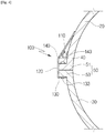
- the second embodiment of the present invention may comprise the flow guide means 100 comprising the flat portion 120, the inclined portion 110, and the bending portion 130; and a buffering bar 140 fixed to an inner surface of the inclined portion 110 by a fastening pin 143.
- the flat portion 120, the inclined portion 110, and the bending portion 130 are the same as those of the first embodiment of the present invention and thus their descriptions will be omitted hereinafter.
- the buffering bar 140 may be provided in a bending shape so that one end thereof is close to the inclined portion 110 and the other end is close to the upper casing 20.
- the buffering bar 140 may be made of a heat-resistance metal material having an elastic property such as a plate spring.
- the buffering bar 140 functions as pushing, by reaction of elasticity, groove and damage by pressure, which may be occurred at the inclined portion 110 by vibration, shock and the like during operation of the turbine, or twist, deformation and the like of the inclined portion 110 due to thermal expansion; and alleviating deformation of the inclined portion 110.
- the buffering bar 140 alleviates damage due to pressure, deformation due to thermal expansion and the like which may occur at the inclined portion 110 during operation of the turbine, thus constantly maintaining the inclined shape of the inclined portion 110 and stably guiding steam flow.
- FIG. 5 is a view illustrating a third embodiment of a flow guide means 100 according to the present invention.
- the third embodiment of the present invention may further comprise a supporting means 150 interposed between the inclined portion 110 and the upper casing 20 to support the flow guide means 100, which comprises the flat portion 120, the inclined portion 110, and the bending portion 130, and the inclined portion 110.
- the flat portion 120, the inclined portion 110, and the bending portion 130 are the same as those of the first embodiment of the present invention and thus their descriptions will be omitted hereinafter.
- the supporting means 150 may comprise a first supporting member 155 interposed between an upper portion of an inner surface of the inclined portion 110 and the upper casing 20, and a second supporting member 159 interposed between a lower portion of an inner surface of the inclined portion 110 and the upper casing 20.
- the first supporting member 155 may comprise a first upper side block 151, a first inner housing 151a, a first guide protrusion 151b, a first elastic body 152, and a first guide groove 154a.
- the first upper side block 151 may be positioned at an upper end of the inner surface of the inclined portion 110; the first inner housing 151a may be formed inside thereof; and the first guide protrusion 151b may be formed at an opening side of the first inner housing 151a. And, the first elastic body 152 may be positioned inside the first inner housing 151a.
- the first lower side block 154 may be fixed to the upper casing 20 and positioned to contact with the first upper side block 151; and the first guide groove 154a seating the first guide protrusion 151b may be formed at an outer side surface of the first upper side block 151.
- the first elastic body 152 may be implemented in a coil spring shape; and the first guide protrusion 151b moves along the first guide groove 154a by an elastic force of the first elastic body 152, thus alleviating groove, damage due to pressure or deformation due to thermal expansion and the like, which may be occurred at the inclined portion 110 during operation of the turbine.
- the above function may be implemented by the second supporting member 159 together.
- the second supporting member 159 may comprise a second upper side block 156, a second lower side block 158, a second inner housing 156a, a second guide protrusion 156b, a second elastic body 157, and a second guide groove 158a.
- the second upper side block 156 may be positioned at a lower end of the inner surface of the inclined portion 110; the second inner housing 156a may be formed inside thereof; and the second guide protrusion 156b may be formed at an opening side of the second inner housing 156a. And, the second elastic body 157 may be positioned inside the second inner housing 156a.
- the second lower side block 158 may be fixed to the upper casing 20 and positioned to contact with the second upper side block 156; and the second guide groove 158a seating the second guide protrusion 156b may be formed at an outer surface of the second upper side block 156
- the second elastic body 157 may be implemented in a coil spring shape; and the second guide protrusion 156b moves along the second guide groove 158a by an elastic force of the second elastic body 157, thus alleviating groove, damage due to pressure or deformation due to thermal expansion and the like, which may be occurred at the inclined portion 110 during operation of the turbine.
- FIG. 6 is a view illustrating a fourth embodiment of a flow guide means according to the present invention.
- the fourth embodiment of the flow guide means 100 may comprise the flat portion 120, the inclined portion 110, and a slope portion 160.
- the flat portion 120 may be positioned close to outer end portions of a flange 51 of the upper casing 20 and a flange 53 of the lower casing 30.
- the inclined portion 110 may be bent by a predetermined angle and connected at an upper end of the flat portion 120; fixed to the upper casing 20; and guide fluid flow which flows in a top-down direction.
- the slope portion 160 may be bent by a predetermined angle and connected at a lower end of the flat portion 120; fixed to the lower casing 30; and prevent occurrence of turbulence of fluid guided by the inclined portion 110.
- Fig. 7 is a view illustrating a fifth embodiment of a flow guide means 100 according to the present invention.
- the fifth embodiment of the flow guide means 100 may comprise the flat portion 120, the inclined portion 110, the slope portion 160, and a guide wing portion 170.
- the flat portion 120 is positioned close to outer end portions of the flange 51 of the upper casing 20 the flange 53 of the lower casing 30.
- the inclined portion 110 may be bent by a predetermined angle and connected at the upper end of the flat portion 120; fixed to the upper casing 20; and guide fluid flow which flows in a top-down direction.
- the slope portion 160 may be bent by a predetermined angle and connected at the lower end of the flat portion 120; fixed to the lower casing 30; and prevent occurrence of turbulence of fluid guided by the inclined portion 110.
- the guide wing portion 170 may be positioned at the inclined portion 110; and distribute fluid flow, which flows in a top-down direction, to an outer side of the flange portion 50.
- An inclined angle between the guide wing portion 170 and the inclined portion 110 may be determined within a range of not affecting steam flow by a component interposed between the inner casing and the outer casing.
- the guide wing portion 170 may be integrally positioned on the inclined portion 110 in a total longitudinal direction of the flange portion 50; or a plurality of the guide wing portion 170 may be shortly divided by a constant interval and positioned along a longitudinal direction of the flange portion 50 on the inclined portion 110.
- the flow guide means 100 may comprise the flat portion 120 positioned close to the flange portion 50; and a curved portion 180 bent by a predetermined curvature and connected at the upper and lower ends of the flat portion 120, fixed to the upper casing 20 and the lower casing 30, and guiding fluid flow which flows in a top-down direction.
- Fluid which flows in a top-down direction due to the above shape, smoothly flows along a curve and goes over the flange portion 50, thus reducing flow resistance at the outer surface of the casing.
- Figs. 9 and 10 are views illustrating a steam pressure status around a casing flange depending on existence of the flow guide means according to the present invention
- Figs. 11 and 12 are views illustrating a steam velocity status around the casing flange depending on existence of the flow guide means according to the present invention
- Figs. 13 and 14 are views illustrating, at other point, the steam velocity status around the casing flange depending on existence of the flow guide means according to the present invention.
- an input value indicated in the drawings basically uses a unit of [Pa] and a velocity basically uses a unit of [m/s], but the value is arbitrarily set and it is not necessarily limited thereto and may have a different value depending on a turbine applied.
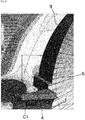
- Fig. 9 when a flange portion 5 connected with an upper casing 3 and a lower casing 4 is exposed to steam flow at a stepped status, the steam flow receives much resistance at a stepped portion of an upper side of the flange portion 5, thus representing a red index or an orange index higher than a surrounding portion thereof.
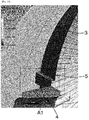
- the steam smoothly flows by the flow guide means 100 covering the flange portion 50, thus representing a red index or an orange index relatively lower than a surrounding portion thereof compared to in Fig. 9 .
- the steam flow flows in a little inclined direction at a portion where the inclined portion 110 starts, thus also representing an orange index lighter than a surround portion thereof.
- a dark orange index or a red index really, largely affects the steam flow, thus finally improving overall steam flow.
- FIG. 11 it is shown in Fig. 11 that the flange portion 5 connected with the upper casing 3 and the lower casing 4 is exposed to steam flow at a stepped status, and thus the steam flow is largely bent at and moves toward an outer side of the flange portion 5.
- An arrow indicates a velocity vector of the steam flow. Accordingly, it is shown that the steam flow passes through an upper portion of the flange 5 and then a fluid velocity of the steam rapidly reduces from a bluish green to a green or a yellow.
- the flow guide means 100 is positioned to cover the flange portion 50 and the steam flow moves along the inclined portion 110, thus also smoothing flow of a velocity vector. To this end, even if the steam flow reaches the flat portion 120 connected to the flange portion 50, it does not experience a rapid change in a fluid velocity. That is, it prevents a rapid change in the flowing direction of the steam, thus further smoothing the steam flow at an outer surface of an inner casing.
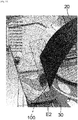
- Fig. 13 the flange portion 5 connected with the upper casing 3 and the lower casing 4 is exposed to steam flow at a stepped status, and thus the steam flow is largely bent at and moves toward an outer side of the flange portion 5. Accordingly, a fluid velocity of the steam rapidly reduces at the flange portion 5.
- Fig. 14 it is shown that the flow guide means 100 is positioned and the fluid velocity of the steam flow at the flange portion 50 is relatively faster than in Fig. 13 . That is, it is confirmed that a blue region at a surrounding portion of the flow guide means 100 is formed wider than in Fig. 13 .
- the present invention has the advantage in that the flow guide means 100 is positioned at the flange portion 50 and the steam flow, which flows along an outer side circumference of the inner casing, does not receive resistance at the flange portion 50, thus smoothing the steam flow, preventing a rapid change in a flowing direction, and resolving the problem which reduces the fluid velocity.
- the flange portion 50 comprises a center flange portion 57 connecting a center portion of the inner casing; and a side flange portion 55 connecting both end portions of the inner casing; and the flow guide means 100 may be positioned at the center flange 57.
- Figs 15 , 16a , and 16b show a structure of a direction groove 210 according to the present invention
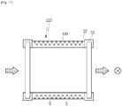
- Figs. 17 , 18a , and 18b show a structure of a direction hole 220 according to the present invention.
- the direction groove 210 may be formed to be spaced apart from a predetermined interval at an outer side of the flow guide means 100 to guide fluid flow.
- the direction groove 210 may comprise a vertical groove portion 211 formed on an upper side of the flow guide means 100 and moving fluid in a downward direction; and a bending groove portion 213 formed to connect with the vertical groove portion 211 at a lower side of the flow guide means 100 and to change the fluid flow of moving in the downward direction.
- the bending groove portion 213 is formed to face a fluid leakage direction at a turbomachine; and the fluid is introduced into the vertical groove portion 211, a direction thereof is changed at the bending groove portion 213, and the fluid flows in the fluid leakage direction.
- a plurality of the direction groove portions 210 are positioned along a longitudinal direction of the flow guide means 100; and bending angles ( ⁇ 1, ⁇ 2, ⁇ 3, ⁇ 4) between a plurality of the bending groove portions 213 may be differently configured.
- the fluid passes through an inner of a casing in an arrow direction and then when exiting in a ground direction (in a condenser direction in a low-pressure turbine among a steam turbine), as shown in Fig. 16a , a bending angle is formed in a ground direction of a rear end of the casing where fluid exits, thus further smoothly guiding fluid flow in an outlet direction.
- the purpose of the above is to maximize effect of direction change.
- Fig. 16b disclosed is that the direction groove 210 is formed at the flat portion 120 of the flow guide means 100.
- the direction hole 220 may be formed to be spaced apart from a predetermined interval at an outer side of the flow guide means 100 to guide fluid flow.
- the direction hole 220 may comprise a vertical hole portion 221 formed on an upper side of the flow guide means 100 and moving fluid in a downward direction; and a bending hole portion 223 formed to connect with the vertical hole portion 221 at a lower side of the flow guide means 100 and changing the fluid flow of moving in the downward direction.
- the bending hole portion 223 is formed to face a fluid leakage direction at a turbomachine; and the fluid is introduced into the vertical hole portion 221, a direction thereof is changed at the bending groove portion 223, and the fluid flows in the fluid leakage direction.
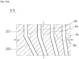
- a plurality of the direction hole portions 220 are positioned along a longitudinal direction of the flow guide means 100; and bending angles ( ⁇ 1, ⁇ 2, ⁇ 3, ⁇ 4) between a plurality of the bending hole portions 223 may be differently configured.
- the fluid passes through an inner of a casing in an arrow direction and then when exiting in a ground direction (in a condenser direction in a low-pressure turbine among a steam turbine), as shown in Fig. 18a , a bending angle is formed in a ground direction of a rear end of the casing where the fluid exits, thus further smoothly guiding fluid flow in an outlet direction.
- the purpose of the above is to maximize effect of direction change.
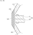
- Fig. 18b disclosed is that the direction hole 220 is formed at the flat portion of the flow guide means 100 by a multilayered structure.
- a casing(12) according to the present disclosure comprise the upper casing 20 comprising an upper portion of a turbomachine(11), positioning the upper flange 51 at an outer side portion, positioning a plurality of diaphragms(22) arranged in a column and mounting a plurality of vanes(21) at an inner surface.
- the lower casing 30 comprises a lower portion of the turbomachine(11), positioning the lower flange 53 at an outer side portion, positioning a plurality of diaphragms(32) arranged in a column and mounting a plurality of vanes(31) at an inner surface.
- the flow guide 100 is positioned to surround the upper casing 51 and the lower flange 53.
- a turbomachine(11) according to the present disclosure comprise the casing(12) described above and a rotor(13) positioned at an inner area of the casing(12) and mounting a plurality of buckets(14) with the plurality of vanes(21,31) alternatively arranged.
- a flow guide structure for a casing flange comprises in the flow guide structure of fluid which flows along an outer surface of a casing of a turbomachine, the flow guide means positioned to seal a flange portion connecting an upper casing and a lower casing which constitutes the casing of the turbomachine; and guiding fluid flow which flows close to the flange portion.
- the flow guide means may comprise a flat portion positioned close to the flange portion; an inclined portion bent at, by a predetermined angle and connected to an upper end of the flat portion, fixed to the upper casing, and guiding the fluid flow which flows in a top-down direction; and a slope portion bent at, by a predetermined angle and connected to a lower end of the flat portion, fixed to the lower casing, and preventing occurrence of turbulence of fluid guided by the inclined portion.
- the flow guide means may further comprise a guide wing portion positioned at the inclined portion and distributing the fluid flow, which flows in the top-down direction, to an outside of the flange portion.
- a buffering bar may be fixed to an inner surface of the inclined portion by a fastening pin.
- a supporting means may be interposed between the inclined portion and the upper casing to support the inclined portion.
- the supporting means may comprise a first supporting member interposed between an upper end of an inner surface of the inclined portion and the upper casing.
- the first supporting member may comprise a first upper side block positioned at the inner surface of the inclined portion; and a first lower side block fixed to the upper casing and positioned to contact with the first upper side block.
- the first supporting member may further comprise a first inner housing formed inside the first upper side block and positioning a first guide protrusion at an opening side; a first elastic body positioned at the first inner housing and contacting with the first lower side block; and a first guide groove formed at an outer surface of the first lower side block and seating the first guide protrusion.
- the supporting means may comprise a second supporting member interposed between a lower portion of the inner surface of the inclined portion and the upper casing.
- the second supporting member may comprise a second upper side block fixed to a second upper plate positioned at the inner surface of the inclined portion; and a second lower side block fixed to a second lower plate positioned at the upper casing and positioned to contact with the second upper side block.
- the second supporting member may further comprise a second inner housing formed inside the second upper side block and positioning a second guide protrusion at an opening side; a second elastic body positioned at the second inner housing and contacting with the second lower side block; and a second guide groove formed at an outer surface of the second lower side block and seating the second guide protrusion.
- a direction groove may be formed to be spaced apart from a predetermined interval at the outer side of the flow guide means to guide fluid flow.
- the direction groove may comprise a vertical groove portion formed at an upper side of the flow guide means and moving fluid in a downward direction; and a bending groove portion formed to connect with the vertical groove portion at a lower side of the flow guide means and changing fluid flow of moving in the downward direction.
- a plurality of the direction grooves may be positioned along a longitudinal direction of the flow guide means. Bending angles between a plurality of the bending groove portions may be different.
- a direction hole may be formed to be spaced apart from a predetermined interval at the outer side of the flow guide means to guide fluid flow.
- the direction hole may comprise a vertical hole portion formed at an upper side of the flow guide means and moving fluid in a downward direction; and a bending hole portion formed to connect with the vertical hole portion at a lower side of the flow guide means and changing the fluid flow of moving in the downward direction.
- a plurality of the direction holes may be positioned along a longitudinal direction of the flow guide means. Bending angles between a plurality of the bending hole portions may be different.
Landscapes
- Engineering & Computer Science (AREA)
- Mechanical Engineering (AREA)
- General Engineering & Computer Science (AREA)
- Turbine Rotor Nozzle Sealing (AREA)
- Structures Of Non-Positive Displacement Pumps (AREA)
Abstract
Description
- Exemplary embodiments of the present invention relate to a flow guide structure for a casing flange, and a casing and a turbomachine having the same, and more particularly, to a structure reducing steam flow resistance around a casing flange and smoothing steam flow.
- Generally, a turbomachine is a power generation apparatus converting a thermal energy of fluid, such as gas, steam and the like into a rotating force being a mechanical energy, and comprises a rotor having a plurality of buckets to perform shaft rotation by the fluid and a casing installed to surround the rotor and having a plurality of diaphragms.
- Herein, a gas turbine includes a compressor section, a combustor, and a turbine section; an external air is inhaled and compressed by rotation of the compressor section and then sent to the combustor, and burnt by a mixture of the compressed air and fuel in the combustor. A high temperature/high pressure of gas generated in the combustor rotates the rotor of the turbine while passing through the turbine section, and thus operates a generator.
- In a steam turbine, it serially or in parallel connects a high-pressure turbine section, an intermediate-pressure turbine section, and a low-pressure turbine section and rotates a rotor; in the serially connected structure, the high-pressure turbine section, the medium-pressure turbine section, and the low-pressure turbine section share one rotor.
- Each of turbines in the steam turbine includes a bucket and a diaphragm around a rotor inside a casing, and steam rotates the rotor while passing through the bucket and the diaphragm, and thus operates a generator.
- In
Fig. 1 , an inner casing of a low-pressure turbine inside a steam turbine is shown. Power steam passes through a high-pressure turbine, an intermediate-pressure turbine, and a low-pressure turbine in order, and then finally flows toward a condenser positioned at a lower end portion of the low-pressure turbine. Accordingly, the power steam discharged through adiaphragm 2 of the low-pressure turbine moves in a direction of the lower end of the low-pressure turbine. - At this time, some steam positioned at the
diaphragm 2 flows along a circumference of an outer side of the inner casing from an upward direction to a downward direction. The inner casing has a structure with anupper casing 3 and alower casing 4 coupled byflanges - Consequently, steam flowing along the circumference of the outer side of the low-pressure turbine receives flow resistance at the
flanges Fig. 2 . The steam moving in a downward direction along the circumference of the outer side of the upper casing receives flow resistance bent by a 90-degree angle at theflange 5a around a reference numeral Y, and then a fluid velocity largely reduces and a flow direction also experiences a rapid change. - Some occurs turbulence at a lower end portion of the
flange 5b. It stems from the stepped shape of theflanges - (Patent Document 1)
US Patent No. 635204 - The present invention is proposed for resolving the above problems of a conventional technology, and the object of the present invention is to provide a structure reducing steam flow resistance around a casing flange and thus smoothing steam flow.
- Other objects and advantages of the present invention can be understood by the following description, and become apparent with reference to the embodiments of the present invention. Also, it is obvious to those skilled in the art to which the present invention pertains that the objects and advantages of the present invention can be realized by the means as claimed and combinations thereof.
- The present invention for achieving the above objects relates to a flow guide structure for a casing flange, and a casing and a turbomachine having the same, and may comprise a flow guide means positioned to seal a flange portion connecting an upper casing and a lower casing and guiding fluid flow which flows close to the flange portion.
- Further, in accordance with the present invention, the flow guide means may comprise a flat portion positioned close to the flange portion; an inclined portion bent at, by a predetermined angle and connected to an upper end of the flat portion, fixed to the upper casing, and guiding the fluid flow which flows in a top-down direction; and a bending portion bent at a lower end of the flat portion and fixed to the lower end of the flat portion.
- Further, in accordance with the present invention, the flow guide means may comprise a flat portion positioned close to the flange portion; an inclined portion bent at, by a predetermined angle and connected to an upper end of the flat portion, fixed to the upper casing, and guiding the fluid flow which flows in a top-down direction; and a slope portion bent at, by a predetermined angle and connected to a lower end of the flat portion, fixed to the lower casing, and preventing occurrence of turbulence of fluid guided by the inclined portion.
- Further, in accordance with the present invention, the flow guide means further may comprise a guide wing portion positioned at the inclined portion and distributing the fluid flow, which flows in the top-down direction, to an outer side of the flange portion.
- Further, in accordance with the present invention, the flow guide means further may comprise a buffering bar fixed to an inner surface of the inclined portion by a fastening pin, and wherein one end of the buffering bar is close to the inclined portion and other end of the buffering bar is bent close to the upper casing.
- Further, in accordance with the present invention, the flow guide means further may comprise a supporting means interposed between the inclined portion and the upper casing to support the inclined portion.
- Further, in accordance with the present invention, the supporting means may comprise a first supporting member interposed between an upper end of an inner surface of the inclined portion and the upper casing, and wherein the first supporting member comprises a first upper side block positioned at the inner surface of the inclined portion; and a first lower side block fixed to the upper casing and positioned to contact with the first upper side block.
- Further, in accordance with the present invention, the first supporting member further may comprise a first inner housing formed inside the first upper side block and positioning a first guide protrusion at an opening side; a first elastic body positioned at the first inner housing and contacting with the first lower side block; and a first guide groove formed at an outer surface of the first lower side block and seating the first guide protrusion.
- Further, in accordance with the present invention, the supporting means may comprise a second supporting member interposed between a lower portion of the inner surface of the inclined portion and the upper casing, and wherein the second supporting member may comprises a second upper side block fixed to a second upper plate positioned at the inner surface of the inclined portion; and a second lower side block fixed to a second lower plate positioned at the upper casing and positioned to contact with the second upper side block.
- Further, in accordance with the present invention, the second supporting member further may comprise a second inner housing formed inside the second upper side block and positioning a second guide protrusion at an opening side; a second elastic body positioned at the second inner housing and contacting with the second lower side block; and a second guide groove formed at an outer surface of the second lower side block and seating the second guide protrusion.
- Further, in accordance with the present invention, the flow guide means may comprise a flat portion positioned close to the flange portion; and a curved portion bent at, by a predetermined curvature and connected to an upper end and a lower end of the flat portion, fixed to the upper casing and the lower casing, and guiding fluid flow which flows in a top-down direction.
- Further, in accordance with the present invention, the flange portion may comprise a center flange connecting a center portion of the inner casing and a side flange connecting both end portions of the inner casing, and wherein the flow guide means is positioned at the center flange.
- Further, in accordance with the present invention, a direction groove may be formed to be spaced apart from a predetermined interval at the outer side of the flow guide means to guide fluid flow.
- Further, in accordance with the present invention, the direction groove may comprise a vertical groove portion formed at an upper side of the flow guide means and moving fluid in a downward direction; and a bending groove portion formed to connect with the vertical groove portion at a lower side of the flow guide means and changing the fluid flow of moving in the downward direction.
- Further, in accordance with the present invention, a plurality of the direction grooves may be positioned along a longitudinal direction of the flow guide means; and bending angles between a plurality of the bending groove portions are different.
- Further, in accordance with the present invention, a direction hole may be formed to be spaced apart from a predetermined interval at the outer side of the flow guide means to guide fluid flow.
- Further, in accordance with the present invention, the direction hole may comprise a vertical hole portion formed at an upper side of the flow guide means and moving fluid in a downward direction; and a bending hole portion formed to connect with the vertical hole portion at a lower side of the flow guide means and changing the fluid flow of moving in the downward direction.
- Further, in accordance with the present invention, a plurality of the direction holes may be positioned along a longitudinal direction of the flow guide means and bending angles between a plurality of the bending groove portions are different.
- Further, a casing according to the present invention may comprise a upper casing constituting an upper of a turbomachine, positioning an upper flange at an outer side portion, and positioning a plurality of diaphragms in multiple columns with a plurality of vanes mounted on an inner surface; a lower casing constituting a lower of the turbomachine, positioning a lower flange at the outer side portion, and positioning by a plurality of diaphragms in multiple columns with a plurality of vanes mounted on the inner surface; and the flow guide structure for the casing flange positioned to surround the upper flange and the lower flange.
- Further, a turbomachine according to the present invention may comprise a casing; and a rotor positioned inside the casing and mounting a plurality of buckets with a plurality of vanes alternatively arranged.
- According to the present invention, it is possible to guide fluid flow around the casing flange and reduce flow resistance, thus smoothing the fluid flow and ultimately improving efficiency of the turbine.
- It is to be understood that both the foregoing general description and the following detailed description of the present invention are exemplary and explanatory and are intended to provide further explanation of the invention as claimed.
- The above and other objects, features and other advantages of the present invention will be more clearly understood from the following detailed description taken in conjunction with the accompanying drawings, in which:
-
Fig. 1 is a view illustrating steam flow in a conventional casing; -
Fig. 2 is a view illustrating steam flow around a conventional casing flange; -
Fig. 3 is a view illustrating a first embodiment of a flow guide means according to the present invention; -
Fig. 4 is a view illustrating a second embodiment of the flow guide means according to the present invention; -
Fig. 5 is a view illustrating a third embodiment of the flow guide means according to the present invention; -
Fig. 6 is a view illustrating a fourth embodiment of the flow guide means according to the present invention; -
Fig. 7 is a view illustrating a fifth embodiment of the flow guide means according to the present invention; -
Fig. 8 is a view illustrating a sixth embodiment of the flow guide means according to the present invention; -
Figs. 9 and10 are views illustrating a steam pressure status around a casing flange depending on existence of the flow guide means according to the present invention; -
Figs. 11 and12 are views illustrating a steam velocity status around the casing flange depending on existence of the flow guide means according to the present invention; -
Figs. 13 and14 are views illustrating, at other point, the steam velocity status around the casing flange depending on existence of the flow guide structure according to the present invention; -
Fig. 15 is a view illustrating a direction groove according to the present invention; -
Figs. 16a and16b are views illustrating a detailed structure of the direction groove shown inFig. 15 ; -
Fig. 17 is a view illustrating a direction hole according to the present invention; and -
Figs. 18a and18b are views illustrating a detailed structure of the direction hole shown inFig. 17 . -
Fig. 19 is a view showing a casing and a turbo machine. - Reference will now be made in detail to various embodiments of the present invention, examples of which are illustrated in the accompanying drawings and described below. The present invention may, however, be embodied in different forms and should not be construed as limited to the embodiments set forth herein. The present invention is intended to cover not only the exemplary embodiments, but also various alternatives, modifications, equivalents, replacements and other embodiments, which may be included within the spirit and scope of the present invention as defined by the appended claims. In the drawings, the thickness of each line or the size of each component may be exaggerated or schematically illustrated for convenience of description and clarity.
- In addition, the terms used in the specification are terms defined in consideration of functions in the present invention, and these terms may vary with the intention or practice of a user or an operator. Therefore, these terms should be defined based on the entire content disclosed herein.
- Hereinafter, preferable exemplary embodiments of a flow guide structure for a casing flange, and a casing and a turbomachine having the same according to the present invention will be described in detail with reference to the accompanying drawings.
-
Fig. 3 is a view illustrating a first embodiment of a flow guide means 100 according to the present invention. - Referring to
Fig. 3 , a flow guide structure for a casing flange according to the present invention may comprise a flow guide means 100 positioned to seal aflange portion 50 connecting anupper casing 20 and alower casing 30 and guiding fluid flow which flows adjacent to theflange portion 50. - The flow guide means 100 may comprise a
flat portion 120, aninclined portion 110, and a bendingportion 130. - First, the
flat portion 120 may be positioned close to outer end portions of aflange 51 of theupper casing 20 and aflange 53 of thelower casing 30. - The
flange portion 50 indicates theupper flange 51 and thelower flange 53. Theupper flange 51 and thelower flange 53 may be coupled by afastener 40. - And, the
inclined portion 110 may be bent by a predetermined angle and connected to an upper end of theflat portion 120; fixed to theupper casing 20; and guiding fluid flow which flows in a top-down direction. As shown inFig. 3 , theinclined portion 110 may be fixed to theupper casing 20 by fastening abolt 113 into a fastening hole, which is formed on an upper side of theinclined portion 110. The fastening hole may be made in a groove shape not to disturb steam flow. - Next, the bending
portion 130 may be bent at and fixed to a lower end of theflat portion 120. The bendingportion 130 may be fixed to a lower end of theflange 53 of thelower casing 30 by thebolt 133. - Due to the above structure, as shown in
Fig. 1 , some steam, which is ejected, bypasses, and flows at the inner casing of the turbine, moves along theinclined portion 110, thus not receiving flow resistance at the upper end of theflange portion 50 sealed. That is, flow at theflange portion 50 of the inner casing becomes smoothed. - Meanwhile,
Fig. 4 is a view illustrating a second embodiment of the flow guide means 100 according to the present invention. - Referring to
Fig. 4 , the second embodiment of the present invention may comprise the flow guide means 100 comprising theflat portion 120, theinclined portion 110, and the bendingportion 130; and abuffering bar 140 fixed to an inner surface of theinclined portion 110 by afastening pin 143. Herein, theflat portion 120, theinclined portion 110, and the bendingportion 130 are the same as those of the first embodiment of the present invention and thus their descriptions will be omitted hereinafter. - The
buffering bar 140 may be provided in a bending shape so that one end thereof is close to theinclined portion 110 and the other end is close to theupper casing 20. Thebuffering bar 140 may be made of a heat-resistance metal material having an elastic property such as a plate spring. - The
buffering bar 140 functions as pushing, by reaction of elasticity, groove and damage by pressure, which may be occurred at theinclined portion 110 by vibration, shock and the like during operation of the turbine, or twist, deformation and the like of theinclined portion 110 due to thermal expansion; and alleviating deformation of theinclined portion 110. - Due to the above structure, as shown in
Fig. 1 , some steam, which is ejected, bypasses, and flows at the inner casing of the turbine, moves along theinclined portion 110, thus not receiving flow resistance at the upper end of theflange portion 50 sealed. That is, flow at theflange portion 50 of the inner casing becomes smoothed. - And, the
buffering bar 140 alleviates damage due to pressure, deformation due to thermal expansion and the like which may occur at theinclined portion 110 during operation of the turbine, thus constantly maintaining the inclined shape of theinclined portion 110 and stably guiding steam flow. - Meanwhile,
Fig. 5 is a view illustrating a third embodiment of a flow guide means 100 according to the present invention. - Referring to
Fig. 5 , the third embodiment of the present invention may further comprise a supporting means 150 interposed between theinclined portion 110 and theupper casing 20 to support the flow guide means 100, which comprises theflat portion 120, theinclined portion 110, and the bendingportion 130, and theinclined portion 110. Herein, theflat portion 120, theinclined portion 110, and the bendingportion 130 are the same as those of the first embodiment of the present invention and thus their descriptions will be omitted hereinafter. - The supporting means 150 may comprise a first supporting
member 155 interposed between an upper portion of an inner surface of theinclined portion 110 and theupper casing 20, and a second supportingmember 159 interposed between a lower portion of an inner surface of theinclined portion 110 and theupper casing 20. - The first supporting
member 155 may comprise a firstupper side block 151, a firstinner housing 151a, afirst guide protrusion 151b, a firstelastic body 152, and afirst guide groove 154a. - First, the first
upper side block 151 may be positioned at an upper end of the inner surface of theinclined portion 110; the firstinner housing 151a may be formed inside thereof; and thefirst guide protrusion 151b may be formed at an opening side of the firstinner housing 151a. And, the firstelastic body 152 may be positioned inside the firstinner housing 151a. - The first
lower side block 154 may be fixed to theupper casing 20 and positioned to contact with the firstupper side block 151; and thefirst guide groove 154a seating thefirst guide protrusion 151b may be formed at an outer side surface of the firstupper side block 151. - The first
elastic body 152 may be implemented in a coil spring shape; and thefirst guide protrusion 151b moves along thefirst guide groove 154a by an elastic force of the firstelastic body 152, thus alleviating groove, damage due to pressure or deformation due to thermal expansion and the like, which may be occurred at theinclined portion 110 during operation of the turbine. - The above function may be implemented by the second supporting
member 159 together. - The second supporting
member 159 may comprise a secondupper side block 156, a secondlower side block 158, a secondinner housing 156a, asecond guide protrusion 156b, a secondelastic body 157, and asecond guide groove 158a. - First, the second
upper side block 156 may be positioned at a lower end of the inner surface of theinclined portion 110; the secondinner housing 156a may be formed inside thereof; and thesecond guide protrusion 156b may be formed at an opening side of the secondinner housing 156a. And, the secondelastic body 157 may be positioned inside the secondinner housing 156a. - The second
lower side block 158 may be fixed to theupper casing 20 and positioned to contact with the secondupper side block 156; and thesecond guide groove 158a seating thesecond guide protrusion 156b may be formed at an outer surface of the secondupper side block 156 - The second
elastic body 157 may be implemented in a coil spring shape; and thesecond guide protrusion 156b moves along thesecond guide groove 158a by an elastic force of the secondelastic body 157, thus alleviating groove, damage due to pressure or deformation due to thermal expansion and the like, which may be occurred at theinclined portion 110 during operation of the turbine. - Meanwhile,
Fig. 6 is a view illustrating a fourth embodiment of a flow guide means according to the present invention. - Referring to
Fig. 6 , the fourth embodiment of the flow guide means 100 according to the present invention may comprise theflat portion 120, theinclined portion 110, and aslope portion 160. - First, the
flat portion 120 may be positioned close to outer end portions of aflange 51 of theupper casing 20 and aflange 53 of thelower casing 30. - And, the
inclined portion 110 may be bent by a predetermined angle and connected at an upper end of theflat portion 120; fixed to theupper casing 20; and guide fluid flow which flows in a top-down direction. - Next, the
slope portion 160 may be bent by a predetermined angle and connected at a lower end of theflat portion 120; fixed to thelower casing 30; and prevent occurrence of turbulence of fluid guided by theinclined portion 110. - Due to the above structure, as shown in
Fig. 1 , some steam, which is ejected, bypasses, and flows at the inner casing of the turbine, moves along theinclined portion 110, thus not receiving flow resistance at the upper end of theflange portion 50 sealed. That is, flow at theflange portion 50 of the inner casing becomes smoothed. - And, steam moves along the
slope portion 160 at the lower end of theflange portion 50, thus not occurring turbulence of some steam at thelower flange 53. - Meanwhile,
Fig. 7 is a view illustrating a fifth embodiment of a flow guide means 100 according to the present invention. - Referring to
Fig. 7 , the fifth embodiment of the flow guide means 100 according to the present invention may comprise theflat portion 120, theinclined portion 110, theslope portion 160, and aguide wing portion 170. - First, the
flat portion 120 is positioned close to outer end portions of theflange 51 of theupper casing 20 theflange 53 of thelower casing 30. - And, the
inclined portion 110 may be bent by a predetermined angle and connected at the upper end of theflat portion 120; fixed to theupper casing 20; and guide fluid flow which flows in a top-down direction. - Next, the
slope portion 160 may be bent by a predetermined angle and connected at the lower end of theflat portion 120; fixed to thelower casing 30; and prevent occurrence of turbulence of fluid guided by theinclined portion 110. - Further, the
guide wing portion 170 may be positioned at theinclined portion 110; and distribute fluid flow, which flows in a top-down direction, to an outer side of theflange portion 50. An inclined angle between theguide wing portion 170 and theinclined portion 110 may be determined within a range of not affecting steam flow by a component interposed between the inner casing and the outer casing. - And, the
guide wing portion 170 may be integrally positioned on theinclined portion 110 in a total longitudinal direction of theflange portion 50; or a plurality of theguide wing portion 170 may be shortly divided by a constant interval and positioned along a longitudinal direction of theflange portion 50 on theinclined portion 110. - Due to the above structure, as shown in
Fig. 1 , some steam, which is ejected, bypasses, and flows at the inner casing of the turbine, moves along theinclined portion 110, thus not receiving flow resistance at the upper end of theflange portion 50 sealed. That is, flow at theflange portion 50 of the inner casing becomes smoothed. - At this time, fluid flow is distributed to an outside by the
guide wing portion 170, thus further reducing steam flow resistance. - And, steam moves along the
slope portion 160 at the lower end of theflange portion 50, thus not occurring turbulence of some steam at the lower end of thelower flange 53. - Next, referring to
Fig. 14 , a sixth embodiment of a flow guide means 100 according to the present invention is shown. The flow guide means 100 may comprise theflat portion 120 positioned close to theflange portion 50; and acurved portion 180 bent by a predetermined curvature and connected at the upper and lower ends of theflat portion 120, fixed to theupper casing 20 and thelower casing 30, and guiding fluid flow which flows in a top-down direction. - Fluid, which flows in a top-down direction due to the above shape, smoothly flows along a curve and goes over the
flange portion 50, thus reducing flow resistance at the outer surface of the casing. - The embodiments of the present invention are as described above; and experimental data of steam flow according to the first embodiment of the present invention will be described hereinafter.
-
Figs. 9 and10 are views illustrating a steam pressure status around a casing flange depending on existence of the flow guide means according to the present invention;Figs. 11 and12 are views illustrating a steam velocity status around the casing flange depending on existence of the flow guide means according to the present invention; andFigs. 13 and14 are views illustrating, at other point, the steam velocity status around the casing flange depending on existence of the flow guide means according to the present invention. - Hereinafter, an input value indicated in the drawings basically uses a unit of [Pa] and a velocity basically uses a unit of [m/s], but the value is arbitrarily set and it is not necessarily limited thereto and may have a different value depending on a turbine applied.
- First, referring to
Figs. 9 and10 , inFig. 9 , when aflange portion 5 connected with anupper casing 3 and alower casing 4 is exposed to steam flow at a stepped status, the steam flow receives much resistance at a stepped portion of an upper side of theflange portion 5, thus representing a red index or an orange index higher than a surrounding portion thereof. - By comparison, referring to
Fig. 10 , the steam smoothly flows by the flow guide means 100 covering theflange portion 50, thus representing a red index or an orange index relatively lower than a surrounding portion thereof compared to inFig. 9 . - However, the steam flow flows in a little inclined direction at a portion where the
inclined portion 110 starts, thus also representing an orange index lighter than a surround portion thereof. However, a dark orange index or a red index really, largely affects the steam flow, thus finally improving overall steam flow. - In the present experiment, the darker the red index becomes, the higher a pressure is; and the darker a blue index becomes, the lower a pressure is.
- Next, referring to
Figs. 11 and12 , it is shown inFig. 11 that theflange portion 5 connected with theupper casing 3 and thelower casing 4 is exposed to steam flow at a stepped status, and thus the steam flow is largely bent at and moves toward an outer side of theflange portion 5. An arrow indicates a velocity vector of the steam flow. Accordingly, it is shown that the steam flow passes through an upper portion of theflange 5 and then a fluid velocity of the steam rapidly reduces from a bluish green to a green or a yellow. - By comparison, in
Fig. 11 , the flow guide means 100 is positioned to cover theflange portion 50 and the steam flow moves along theinclined portion 110, thus also smoothing flow of a velocity vector. To this end, even if the steam flow reaches theflat portion 120 connected to theflange portion 50, it does not experience a rapid change in a fluid velocity. That is, it prevents a rapid change in the flowing direction of the steam, thus further smoothing the steam flow at an outer surface of an inner casing. - In the present experiment, the darker yellow and red become, the more flow resistance of a fluid velocity vector receives; and the darker green and blue become, the less flow resistance of a fluid velocity vector receives
- Next, referring to
Figs. 13 and14 , inFig. 13 , theflange portion 5 connected with theupper casing 3 and thelower casing 4 is exposed to steam flow at a stepped status, and thus the steam flow is largely bent at and moves toward an outer side of theflange portion 5. Accordingly, a fluid velocity of the steam rapidly reduces at theflange portion 5. - By comparison, referring to
Fig. 14 , it is shown that the flow guide means 100 is positioned and the fluid velocity of the steam flow at theflange portion 50 is relatively faster than inFig. 13 . That is, it is confirmed that a blue region at a surrounding portion of the flow guide means 100 is formed wider than inFig. 13 . - In the present experiment, the darker red becomes, the slower a fluid velocity is; and the darker blue becomes, the faster the fluid velocity is.
- Like the above experimental data, the present invention has the advantage in that the flow guide means 100 is positioned at the
flange portion 50 and the steam flow, which flows along an outer side circumference of the inner casing, does not receive resistance at theflange portion 50, thus smoothing the steam flow, preventing a rapid change in a flowing direction, and resolving the problem which reduces the fluid velocity. - Next, referring to
Figs. 15 to 17 , theflange portion 50 comprises acenter flange portion 57 connecting a center portion of the inner casing; and aside flange portion 55 connecting both end portions of the inner casing; and the flow guide means 100 may be positioned at thecenter flange 57. - Herein,
Figs 15 ,16a , and16b show a structure of adirection groove 210 according to the present invention; andFigs. 17 ,18a , and18b show a structure of adirection hole 220 according to the present invention. - First, referring to
Figs 15 ,16a , and16b , thedirection groove 210 may be formed to be spaced apart from a predetermined interval at an outer side of the flow guide means 100 to guide fluid flow. - The
direction groove 210 may comprise avertical groove portion 211 formed on an upper side of the flow guide means 100 and moving fluid in a downward direction; and a bendinggroove portion 213 formed to connect with thevertical groove portion 211 at a lower side of the flow guide means 100 and to change the fluid flow of moving in the downward direction. - The bending
groove portion 213 is formed to face a fluid leakage direction at a turbomachine; and the fluid is introduced into thevertical groove portion 211, a direction thereof is changed at the bendinggroove portion 213, and the fluid flows in the fluid leakage direction. - At this time, a plurality of the
direction groove portions 210 are positioned along a longitudinal direction of the flow guide means 100; and bending angles (θ1,θ2,θ3,θ4) between a plurality of the bendinggroove portions 213 may be differently configured. - According to the above structure, as shown in
Fig. 15 , the fluid passes through an inner of a casing in an arrow direction and then when exiting in a ground direction (in a condenser direction in a low-pressure turbine among a steam turbine), as shown inFig. 16a , a bending angle is formed in a ground direction of a rear end of the casing where fluid exits, thus further smoothly guiding fluid flow in an outlet direction. - Herein, the closer fluid leakage direction the
direction hole 220 at the casing is, the smaller the bending angles (θ1,θ2,θ3,θ4) become. The purpose of the above is to maximize effect of direction change. - In
Fig. 16b , disclosed is that thedirection groove 210 is formed at theflat portion 120 of the flow guide means 100. - Next, referring to
Figs. 17 ,18a , and18b , thedirection hole 220 may be formed to be spaced apart from a predetermined interval at an outer side of the flow guide means 100 to guide fluid flow. - The
direction hole 220 may comprise avertical hole portion 221 formed on an upper side of the flow guide means 100 and moving fluid in a downward direction; and abending hole portion 223 formed to connect with thevertical hole portion 221 at a lower side of the flow guide means 100 and changing the fluid flow of moving in the downward direction. - The bending
hole portion 223 is formed to face a fluid leakage direction at a turbomachine; and the fluid is introduced into thevertical hole portion 221, a direction thereof is changed at the bendinggroove portion 223, and the fluid flows in the fluid leakage direction. - At this time, a plurality of the
direction hole portions 220 are positioned along a longitudinal direction of the flow guide means 100; and bending angles (Φ1,Φ2,Φ3,Φ4) between a plurality of thebending hole portions 223 may be differently configured. - According to the above structure, as shown in
Fig. 17 , the fluid passes through an inner of a casing in an arrow direction and then when exiting in a ground direction (in a condenser direction in a low-pressure turbine among a steam turbine), as shown inFig. 18a , a bending angle is formed in a ground direction of a rear end of the casing where the fluid exits, thus further smoothly guiding fluid flow in an outlet direction. - Herein, the closer fluid leakage direction the
direction hole 220 at the casing is, the smaller the bending angles (Φ1,Φ2,Φ3,Φ4) become. The purpose of the above is to maximize effect of direction change. - In
Fig. 18b , disclosed is that thedirection hole 220 is formed at the flat portion of the flow guide means 100 by a multilayered structure. - Meanwhile,
Fig. 19 shows, a casing(12) according to the present disclosure comprise theupper casing 20 comprising an upper portion of a turbomachine(11), positioning theupper flange 51 at an outer side portion, positioning a plurality of diaphragms(22) arranged in a column and mounting a plurality of vanes(21) at an inner surface. Thelower casing 30 comprises a lower portion of the turbomachine(11), positioning thelower flange 53 at an outer side portion, positioning a plurality of diaphragms(32) arranged in a column and mounting a plurality of vanes(31) at an inner surface. Theflow guide 100 is positioned to surround theupper casing 51 and thelower flange 53. - Further, a turbomachine(11) according to the present disclosure comprise the casing(12) described above and a rotor(13) positioned at an inner area of the casing(12) and mounting a plurality of buckets(14) with the plurality of vanes(21,31) alternatively arranged.
- The above descriptions are only certain embodiments of a flow guide structure for a casing flange.
According to a preferred embodiment, a flow guide structure for a casing flange, comprises in the flow guide structure of fluid which flows along an outer surface of a casing of a turbomachine, the flow guide means positioned to seal a flange portion connecting an upper casing and a lower casing which constitutes the casing of the turbomachine; and guiding fluid flow which flows close to the flange portion. The flow guide means may comprise a flat portion positioned close to the flange portion; an inclined portion bent at, by a predetermined angle and connected to an upper end of the flat portion, fixed to the upper casing, and guiding the fluid flow which flows in a top-down direction; and a slope portion bent at, by a predetermined angle and connected to a lower end of the flat portion, fixed to the lower casing, and preventing occurrence of turbulence of fluid guided by the inclined portion. The flow guide means may further comprise a guide wing portion positioned at the inclined portion and distributing the fluid flow, which flows in the top-down direction, to an outside of the flange portion. A buffering bar may be fixed to an inner surface of the inclined portion by a fastening pin. One end of the buffering bar may be close to the inclined portion and other end of the buffering bar may be bent close to the upper casing. A supporting means may be interposed between the inclined portion and the upper casing to support the inclined portion. The supporting means may comprise a first supporting member interposed between an upper end of an inner surface of the inclined portion and the upper casing. The first supporting member may comprise a first upper side block positioned at the inner surface of the inclined portion; and a first lower side block fixed to the upper casing and positioned to contact with the first upper side block. The first supporting member may further comprise a first inner housing formed inside the first upper side block and positioning a first guide protrusion at an opening side; a first elastic body positioned at the first inner housing and contacting with the first lower side block; and a first guide groove formed at an outer surface of the first lower side block and seating the first guide protrusion. The supporting means may comprise a second supporting member interposed between a lower portion of the inner surface of the inclined portion and the upper casing. The second supporting member may comprise a second upper side block fixed to a second upper plate positioned at the inner surface of the inclined portion; and a second lower side block fixed to a second lower plate positioned at the upper casing and positioned to contact with the second upper side block. The second supporting member may further comprise a second inner housing formed inside the second upper side block and positioning a second guide protrusion at an opening side; a second elastic body positioned at the second inner housing and contacting with the second lower side block; and a second guide groove formed at an outer surface of the second lower side block and seating the second guide protrusion. A direction groove may be formed to be spaced apart from a predetermined interval at the outer side of the flow guide means to guide fluid flow. The direction groove may comprise a vertical groove portion formed at an upper side of the flow guide means and moving fluid in a downward direction; and a bending groove portion formed to connect with the vertical groove portion at a lower side of the flow guide means and changing fluid flow of moving in the downward direction. A plurality of the direction grooves may be positioned along a longitudinal direction of the flow guide means. Bending angles between a plurality of the bending groove portions may be different. A direction hole may be formed to be spaced apart from a predetermined interval at the outer side of the flow guide means to guide fluid flow. The direction hole may comprise a vertical hole portion formed at an upper side of the flow guide means and moving fluid in a downward direction; and a bending hole portion formed to connect with the vertical hole portion at a lower side of the flow guide means and changing the fluid flow of moving in the downward direction. A plurality of the direction holes may be positioned along a longitudinal direction of the flow guide means. Bending angles between a plurality of the bending hole portions may be different. - While the present invention has been described with respect to the specific embodiments, it will be apparent to those skilled in the art that various changes and modifications may be made without departing from the scope of the invention as defined in the following claims.
Claims (15)
- A casing for a turbomachine, comprising:an upper casing and a lower casing;a flange portion connecting the upper and the lower casing;a flow guide structure including a flow guide means positioned at the flange portion of the casing for guiding fluid flow along an outer surface of the casing adjacent to the flange portion.
- The flow guide structure for the casing flange according to claim 1, wherein the flow guide means comprising:a flat portion positioned close to the flange portion;an inclined portion bent at, by a predetermined angle and connected to an upper end of the flat portion, fixed to the upper casing, and guiding the fluid flow which flows in a top-down direction; anda slope portion bent at, by a predetermined angle and connected to a lower end of the flat portion, fixed to the lower casing, and preventing occurrence of turbulence of fluid guided by the inclined portion.
- The flow guide structure for the casing flange according to claim 2, whether the flow guide means further comprises a guide wing portion positioned at the inclined portion and distributing the fluid flow, which flows in the top-down direction, to an outside of the flange portion.
- The flow guide structure for the casing flange according to claim 2 or 3, further comprising a buffering bar fixed to an inner surface of the inclined portion by a fastening pin, and wherein one end of the buffering bar is close to the inclined portion and other end of the buffering bar is bent close to the upper casing.
- The flow guide structure for the casing flange according to any one of claims 2 to 4, further comprising a supporting means interposed between the inclined portion and the upper casing to support the inclined portion.
- The flow guide structure for the casing flange according to claim 5, wherein the supporting means comprises a first supporting member interposed between an upper end of an inner surface of the inclined portion and the upper casing, and wherein the first supporting member comprising:a first upper side block positioned at the inner surface of the inclined portion; anda first lower side block fixed to the upper casing and positioned to contact with the first upper side block.
- The flow guide structure for the casing flange according to claim 6, wherein the first supporting member further comprising:a first inner housing formed inside the first upper side block and positioning a first guide protrusion at an opening side;a first elastic body positioned at the first inner housing and contacting with the first lower side block; anda first guide groove formed at an outer surface of the first lower side block and seating the first guide protrusion.
- The flow guide structure for the casing flange according to claim 6 or 7, wherein the supporting means comprises a second supporting member interposed between a lower portion of the inner surface of the inclined portion and the upper casing, and wherein the second supporting member comprising:a second upper side block fixed to a second upper plate positioned at the inner surface of the inclined portion; anda second lower side block fixed to a second lower plate positioned at the upper casing and positioned to contact with the second upper side block.
- The flow guide structure for the casing flange according to claim 8, wherein the second supporting member further comprising:a second inner housing formed inside the second upper side block and positioning a second guide protrusion at an opening side;a second elastic body positioned at the second inner housing and contacting with the second lower side block; anda second guide groove formed at an outer surface of the second lower side block and seating the second guide protrusion.
- The flow guide structure for the casing flange according to any one of claims 1 to 9, wherein a direction groove is formed to be spaced apart from a predetermined interval at the outer side of the flow guide means to guide fluid flow.
- The flow guide structure for the casing flange according to claim 10, wherein the direction groove comprising:a vertical groove portion formed at an upper side of the flow guide means and moving fluid in a downward direction; anda bending groove portion formed to connect with the vertical groove portion at a lower side of the flow guide means and changing fluid flow of moving in the downward direction.
- The flow guide structure for the casing flange according to claim 10 or 11, wherein a plurality of the direction grooves are positioned along a longitudinal direction of the flow guide means; and bending angles between a plurality of the bending groove portions are different.
- The flow guide structure for the casing flange according to any one of claims 1 to 9, wherein a direction hole is formed to be spaced apart from a predetermined interval at the outer side of the flow guide means to guide fluid flow.
- The flow guide structure for the casing flange according to claim 13, wherein the direction hole comprising:a vertical hole portion formed at an upper side of the flow guide means and moving fluid in a downward direction; anda bending hole portion formed to connect with the vertical hole portion at a lower side of the flow guide means and changing the fluid flow of moving in the downward direction.
- The flow guide structure for the casing flange according to claim 13 or 14, wherein a plurality of the direction holes are positioned along a longitudinal direction of the flow guide means; and bending angles between a plurality of the bending hole portions are different.
Applications Claiming Priority (1)
| Application Number | Priority Date | Filing Date | Title |
|---|---|---|---|
| KR1020160146751A KR101821503B1 (en) | 2016-11-04 | 2016-11-04 | Flow guide structure for turbine's inner casing flange |
Publications (3)
| Publication Number | Publication Date |
|---|---|
| EP3318731A1 true EP3318731A1 (en) | 2018-05-09 |
| EP3318731A9 EP3318731A9 (en) | 2018-09-05 |
| EP3318731B1 EP3318731B1 (en) | 2020-04-29 |
Family
ID=60262797
Family Applications (1)
| Application Number | Title | Priority Date | Filing Date |
|---|---|---|---|
| EP17200042.4A Active EP3318731B1 (en) | 2016-11-04 | 2017-11-06 | Flow guide structure for casing flange, and casing and turbomachine having the same |
Country Status (4)
| Country | Link |
|---|---|
| US (1) | US10753233B2 (en) |
| EP (1) | EP3318731B1 (en) |
| JP (1) | JP6485659B2 (en) |
| KR (1) | KR101821503B1 (en) |
Families Citing this family (3)
| Publication number | Priority date | Publication date | Assignee | Title |
|---|---|---|---|---|
| US11542830B2 (en) | 2020-09-11 | 2023-01-03 | Doosan Enerbility Co., Ltd. | Vibration damper, exhaust diffuser system, and gas turbine including same |
| KR102229248B1 (en) | 2020-09-21 | 2021-03-17 | 한전케이피에스 주식회사 | A sealing structure of a turbine casing |
| FR3121168B1 (en) * | 2021-03-23 | 2024-08-30 | Safran Aircraft Engines | Reducing leaks in a turbomachine |
Citations (5)
| Publication number | Priority date | Publication date | Assignee | Title |
|---|---|---|---|---|
| US635204A (en) | 1899-07-15 | 1899-10-17 | Clarence W Taylor | Mucilage-holder. |
| JPS59203811A (en) * | 1983-05-06 | 1984-11-19 | Toshiba Corp | Coupler for casing |
| JPH10196312A (en) * | 1997-01-17 | 1998-07-28 | Mitsubishi Heavy Ind Ltd | Cooling structure of steam turbine casing flange |
| EP1096111A1 (en) * | 1998-06-09 | 2001-05-02 | Mitsubishi Heavy Industries, Ltd. | Cooling architecture for flanges of a steam turbine casing |
| DE102014224419A1 (en) * | 2014-11-28 | 2016-06-02 | Siemens Aktiengesellschaft | Turbine housing arrangement, in particular with an outer housing part and a Abdampfgehäusenteil a steam turbine, and use thereof |
Family Cites Families (13)
| Publication number | Priority date | Publication date | Assignee | Title |
|---|---|---|---|---|
| US1957699A (en) * | 1930-04-25 | 1934-05-08 | Allis Chalmers Mfg Co | Flange connection |
| US1957700A (en) * | 1931-04-16 | 1934-05-08 | Allis Chalmers Mfg Co | Flange connection |
| US2276603A (en) * | 1938-11-04 | 1942-03-17 | Parsons C A & Co Ltd | Butt-jointing device |
| JPS5784304U (en) * | 1980-11-14 | 1982-05-25 | ||
| JPS61160502A (en) * | 1985-01-09 | 1986-07-21 | Fuji Electric Co Ltd | Method of attaching stream guide to turbine casing |
| JPH0196312A (en) | 1987-10-08 | 1989-04-14 | Kawasaki Steel Corp | Apparatus for generating hot blast for metallurgical furnace |
| JP4107766B2 (en) * | 1999-06-15 | 2008-06-25 | 三菱重工業株式会社 | Steam turbine exhaust system |
| JP4146033B2 (en) * | 1999-06-15 | 2008-09-03 | 三菱重工業株式会社 | Steam inlet / outlet pressure loss reduction structure of steam turbine |
| JP4636965B2 (en) * | 2005-08-04 | 2011-02-23 | 株式会社日立製作所 | Turbine exhaust system |
| JP2007120462A (en) * | 2005-10-31 | 2007-05-17 | Toshiba Corp | Steam turbine casing fastening device and steam turbine |
| EP2096272A1 (en) * | 2008-02-27 | 2009-09-02 | Siemens Aktiengesellschaft | Partitioned turbo engine casing with optimised partial joint flange |
| JP2011169246A (en) | 2010-02-19 | 2011-09-01 | Mitsubishi Heavy Ind Ltd | Gas turbine casing structure |
| GB201020213D0 (en) * | 2010-11-30 | 2011-01-12 | Rolls Royce Plc | Nose cone assembly |
-
2016
- 2016-11-04 KR KR1020160146751A patent/KR101821503B1/en active Active
-
2017
- 2017-08-22 JP JP2017159800A patent/JP6485659B2/en active Active
- 2017-11-02 US US15/802,226 patent/US10753233B2/en active Active
- 2017-11-06 EP EP17200042.4A patent/EP3318731B1/en active Active
Patent Citations (5)
| Publication number | Priority date | Publication date | Assignee | Title |
|---|---|---|---|---|
| US635204A (en) | 1899-07-15 | 1899-10-17 | Clarence W Taylor | Mucilage-holder. |
| JPS59203811A (en) * | 1983-05-06 | 1984-11-19 | Toshiba Corp | Coupler for casing |
| JPH10196312A (en) * | 1997-01-17 | 1998-07-28 | Mitsubishi Heavy Ind Ltd | Cooling structure of steam turbine casing flange |
| EP1096111A1 (en) * | 1998-06-09 | 2001-05-02 | Mitsubishi Heavy Industries, Ltd. | Cooling architecture for flanges of a steam turbine casing |
| DE102014224419A1 (en) * | 2014-11-28 | 2016-06-02 | Siemens Aktiengesellschaft | Turbine housing arrangement, in particular with an outer housing part and a Abdampfgehäusenteil a steam turbine, and use thereof |
Also Published As
| Publication number | Publication date |
|---|---|
| KR101821503B1 (en) | 2018-01-23 |
| EP3318731B1 (en) | 2020-04-29 |
| EP3318731A9 (en) | 2018-09-05 |
| JP2018071540A (en) | 2018-05-10 |
| US10753233B2 (en) | 2020-08-25 |
| US20180128127A1 (en) | 2018-05-10 |
| JP6485659B2 (en) | 2019-03-20 |
Similar Documents
| Publication | Publication Date | Title |
|---|---|---|
| CN101779018B (en) | Turbo charger | |
| US6877955B2 (en) | Mixed flow turbine and mixed flow turbine rotor blade | |
| US6883807B2 (en) | Multidirectional turbine shim seal | |
| CN102224323B (en) | A turbomachine with a ring segment positioning member | |
| US8100635B2 (en) | Control of clearance at blade tips in a high-pressure turbine of a turbine engine | |
| KR101409128B1 (en) | Stator vane spring damper | |
| US8147180B2 (en) | Axial flow turbine and stage structure thereof | |
| US9080451B2 (en) | Airfoil | |
| US8142148B2 (en) | Diffuser-nozzle assembly for a turbomachine | |
| EP3318731B1 (en) | Flow guide structure for casing flange, and casing and turbomachine having the same | |
| JP2009144546A (en) | Turbocharger | |
| US8573943B2 (en) | Gas turbine having sealing plates on the turbine disc | |
| US11506086B2 (en) | Turbine housing and turbo charger provided with same | |
| KR20130079326A (en) | Method for adapting the air flow of a turbine engine having a centrifugal compressor and diffuser for implementing same | |
| CN103206726A (en) | Turbine Fuel Nozzle Assembly And Method For Operating A Turbine | |
| CN106123031A (en) | Mixing system | |
| JPWO2019064388A1 (en) | Turbine housing and supercharger provided with the same | |
| CN103032109A (en) | Clearance flow control assembly having rail member | |
| CN107208495B (en) | System for controlling variable pitch blades of a turbine engine | |
| WO2017203962A1 (en) | Supercharger | |
| US6964554B2 (en) | Drop-in nozzle block for steam turbine | |
| JP5461828B2 (en) | Turbomachine module with apparatus for improving radial clearance | |
| JP6504075B2 (en) | Vehicle turbocharger | |
| WO2017175729A1 (en) | Supercharger | |
| US12049829B2 (en) | Heat shield for a supercharging device |
Legal Events
| Date | Code | Title | Description |
|---|---|---|---|
| PUAI | Public reference made under article 153(3) epc to a published international application that has entered the european phase |
Free format text: ORIGINAL CODE: 0009012 |
|
| STAA | Information on the status of an ep patent application or granted ep patent |
Free format text: STATUS: REQUEST FOR EXAMINATION WAS MADE |
|
| 17P | Request for examination filed |
Effective date: 20171106 |
|
| AK | Designated contracting states |
Kind code of ref document: A1 Designated state(s): AL AT BE BG CH CY CZ DE DK EE ES FI FR GB GR HR HU IE IS IT LI LT LU LV MC MK MT NL NO PL PT RO RS SE SI SK SM TR |
|
| AX | Request for extension of the european patent |
Extension state: BA ME |
|
| RAP1 | Party data changed (applicant data changed or rights of an application transferred) |
Owner name: DOOSAN HEAVY INDUSTRIES & CONSTRUCTION CO., LTD. |
|
| RIC1 | Information provided on ipc code assigned before grant |
Ipc: F01D 25/24 20060101AFI20191010BHEP |
|
| GRAP | Despatch of communication of intention to grant a patent |
Free format text: ORIGINAL CODE: EPIDOSNIGR1 |
|
| STAA | Information on the status of an ep patent application or granted ep patent |
Free format text: STATUS: GRANT OF PATENT IS INTENDED |
|
| INTG | Intention to grant announced |
Effective date: 20191203 |
|
| GRAS | Grant fee paid |
Free format text: ORIGINAL CODE: EPIDOSNIGR3 |
|
| GRAA | (expected) grant |
Free format text: ORIGINAL CODE: 0009210 |
|
| STAA | Information on the status of an ep patent application or granted ep patent |
Free format text: STATUS: THE PATENT HAS BEEN GRANTED |
|
| AK | Designated contracting states |
Kind code of ref document: B1 Designated state(s): AL AT BE BG CH CY CZ DE DK EE ES FI FR GB GR HR HU IE IS IT LI LT LU LV MC MK MT NL NO PL PT RO RS SE SI SK SM TR |
|
| REG | Reference to a national code |
Ref country code: GB Ref legal event code: FG4D |
|
| REG | Reference to a national code |
Ref country code: CH Ref legal event code: EP |
|
| REG | Reference to a national code |
Ref country code: DE Ref legal event code: R096 Ref document number: 602017015598 Country of ref document: DE |
|
| REG | Reference to a national code |
Ref country code: AT Ref legal event code: REF Ref document number: 1263647 Country of ref document: AT Kind code of ref document: T Effective date: 20200515 |
|
| REG | Reference to a national code |
Ref country code: IE Ref legal event code: FG4D |
|
| REG | Reference to a national code |
Ref country code: NL Ref legal event code: MP Effective date: 20200429 |
|
| REG | Reference to a national code |
Ref country code: LT Ref legal event code: MG4D |
|
| PG25 | Lapsed in a contracting state [announced via postgrant information from national office to epo] |
Ref country code: LT Free format text: LAPSE BECAUSE OF FAILURE TO SUBMIT A TRANSLATION OF THE DESCRIPTION OR TO PAY THE FEE WITHIN THE PRESCRIBED TIME-LIMIT Effective date: 20200429 Ref country code: NO Free format text: LAPSE BECAUSE OF FAILURE TO SUBMIT A TRANSLATION OF THE DESCRIPTION OR TO PAY THE FEE WITHIN THE PRESCRIBED TIME-LIMIT Effective date: 20200729 Ref country code: FI Free format text: LAPSE BECAUSE OF FAILURE TO SUBMIT A TRANSLATION OF THE DESCRIPTION OR TO PAY THE FEE WITHIN THE PRESCRIBED TIME-LIMIT Effective date: 20200429 Ref country code: SE Free format text: LAPSE BECAUSE OF FAILURE TO SUBMIT A TRANSLATION OF THE DESCRIPTION OR TO PAY THE FEE WITHIN THE PRESCRIBED TIME-LIMIT Effective date: 20200429 Ref country code: IS Free format text: LAPSE BECAUSE OF FAILURE TO SUBMIT A TRANSLATION OF THE DESCRIPTION OR TO PAY THE FEE WITHIN THE PRESCRIBED TIME-LIMIT Effective date: 20200829 Ref country code: PT Free format text: LAPSE BECAUSE OF FAILURE TO SUBMIT A TRANSLATION OF THE DESCRIPTION OR TO PAY THE FEE WITHIN THE PRESCRIBED TIME-LIMIT Effective date: 20200831 Ref country code: GR Free format text: LAPSE BECAUSE OF FAILURE TO SUBMIT A TRANSLATION OF THE DESCRIPTION OR TO PAY THE FEE WITHIN THE PRESCRIBED TIME-LIMIT Effective date: 20200730 |
|
| REG | Reference to a national code |
Ref country code: AT Ref legal event code: MK05 Ref document number: 1263647 Country of ref document: AT Kind code of ref document: T Effective date: 20200429 |
|
| PG25 | Lapsed in a contracting state [announced via postgrant information from national office to epo] |
Ref country code: HR Free format text: LAPSE BECAUSE OF FAILURE TO SUBMIT A TRANSLATION OF THE DESCRIPTION OR TO PAY THE FEE WITHIN THE PRESCRIBED TIME-LIMIT Effective date: 20200429 Ref country code: RS Free format text: LAPSE BECAUSE OF FAILURE TO SUBMIT A TRANSLATION OF THE DESCRIPTION OR TO PAY THE FEE WITHIN THE PRESCRIBED TIME-LIMIT Effective date: 20200429 Ref country code: LV Free format text: LAPSE BECAUSE OF FAILURE TO SUBMIT A TRANSLATION OF THE DESCRIPTION OR TO PAY THE FEE WITHIN THE PRESCRIBED TIME-LIMIT Effective date: 20200429 Ref country code: BG Free format text: LAPSE BECAUSE OF FAILURE TO SUBMIT A TRANSLATION OF THE DESCRIPTION OR TO PAY THE FEE WITHIN THE PRESCRIBED TIME-LIMIT Effective date: 20200729 |
|
| PG25 | Lapsed in a contracting state [announced via postgrant information from national office to epo] |
Ref country code: AL Free format text: LAPSE BECAUSE OF FAILURE TO SUBMIT A TRANSLATION OF THE DESCRIPTION OR TO PAY THE FEE WITHIN THE PRESCRIBED TIME-LIMIT Effective date: 20200429 Ref country code: NL Free format text: LAPSE BECAUSE OF FAILURE TO SUBMIT A TRANSLATION OF THE DESCRIPTION OR TO PAY THE FEE WITHIN THE PRESCRIBED TIME-LIMIT Effective date: 20200429 |
|
| PG25 | Lapsed in a contracting state [announced via postgrant information from national office to epo] |
Ref country code: ES Free format text: LAPSE BECAUSE OF FAILURE TO SUBMIT A TRANSLATION OF THE DESCRIPTION OR TO PAY THE FEE WITHIN THE PRESCRIBED TIME-LIMIT Effective date: 20200429 Ref country code: SM Free format text: LAPSE BECAUSE OF FAILURE TO SUBMIT A TRANSLATION OF THE DESCRIPTION OR TO PAY THE FEE WITHIN THE PRESCRIBED TIME-LIMIT Effective date: 20200429 Ref country code: EE Free format text: LAPSE BECAUSE OF FAILURE TO SUBMIT A TRANSLATION OF THE DESCRIPTION OR TO PAY THE FEE WITHIN THE PRESCRIBED TIME-LIMIT Effective date: 20200429 Ref country code: DK Free format text: LAPSE BECAUSE OF FAILURE TO SUBMIT A TRANSLATION OF THE DESCRIPTION OR TO PAY THE FEE WITHIN THE PRESCRIBED TIME-LIMIT Effective date: 20200429 Ref country code: IT Free format text: LAPSE BECAUSE OF FAILURE TO SUBMIT A TRANSLATION OF THE DESCRIPTION OR TO PAY THE FEE WITHIN THE PRESCRIBED TIME-LIMIT Effective date: 20200429 Ref country code: RO Free format text: LAPSE BECAUSE OF FAILURE TO SUBMIT A TRANSLATION OF THE DESCRIPTION OR TO PAY THE FEE WITHIN THE PRESCRIBED TIME-LIMIT Effective date: 20200429 Ref country code: AT Free format text: LAPSE BECAUSE OF FAILURE TO SUBMIT A TRANSLATION OF THE DESCRIPTION OR TO PAY THE FEE WITHIN THE PRESCRIBED TIME-LIMIT Effective date: 20200429 |
|
| REG | Reference to a national code |
Ref country code: DE Ref legal event code: R097 Ref document number: 602017015598 Country of ref document: DE |
|
| PG25 | Lapsed in a contracting state [announced via postgrant information from national office to epo] |
Ref country code: PL Free format text: LAPSE BECAUSE OF FAILURE TO SUBMIT A TRANSLATION OF THE DESCRIPTION OR TO PAY THE FEE WITHIN THE PRESCRIBED TIME-LIMIT Effective date: 20200429 Ref country code: SK Free format text: LAPSE BECAUSE OF FAILURE TO SUBMIT A TRANSLATION OF THE DESCRIPTION OR TO PAY THE FEE WITHIN THE PRESCRIBED TIME-LIMIT Effective date: 20200429 |
|
| PLBE | No opposition filed within time limit |
Free format text: ORIGINAL CODE: 0009261 |
|
| STAA | Information on the status of an ep patent application or granted ep patent |
Free format text: STATUS: NO OPPOSITION FILED WITHIN TIME LIMIT |
|
| 26N | No opposition filed |
Effective date: 20210201 |
|
| PG25 | Lapsed in a contracting state [announced via postgrant information from national office to epo] |
Ref country code: SI Free format text: LAPSE BECAUSE OF FAILURE TO SUBMIT A TRANSLATION OF THE DESCRIPTION OR TO PAY THE FEE WITHIN THE PRESCRIBED TIME-LIMIT Effective date: 20200429 |
|
| PG25 | Lapsed in a contracting state [announced via postgrant information from national office to epo] |
Ref country code: MC Free format text: LAPSE BECAUSE OF FAILURE TO SUBMIT A TRANSLATION OF THE DESCRIPTION OR TO PAY THE FEE WITHIN THE PRESCRIBED TIME-LIMIT Effective date: 20200429 |
|
| REG | Reference to a national code |
Ref country code: CH Ref legal event code: PL |
|
| PG25 | Lapsed in a contracting state [announced via postgrant information from national office to epo] |
Ref country code: LU Free format text: LAPSE BECAUSE OF NON-PAYMENT OF DUE FEES Effective date: 20201106 |
|
| REG | Reference to a national code |
Ref country code: BE Ref legal event code: MM Effective date: 20201130 |
|
| PG25 | Lapsed in a contracting state [announced via postgrant information from national office to epo] |
Ref country code: LI Free format text: LAPSE BECAUSE OF NON-PAYMENT OF DUE FEES Effective date: 20201130 Ref country code: CH Free format text: LAPSE BECAUSE OF NON-PAYMENT OF DUE FEES Effective date: 20201130 |
|
| PG25 | Lapsed in a contracting state [announced via postgrant information from national office to epo] |
Ref country code: IE Free format text: LAPSE BECAUSE OF NON-PAYMENT OF DUE FEES Effective date: 20201106 Ref country code: FR Free format text: LAPSE BECAUSE OF NON-PAYMENT OF DUE FEES Effective date: 20201130 |
|
| PG25 | Lapsed in a contracting state [announced via postgrant information from national office to epo] |
Ref country code: TR Free format text: LAPSE BECAUSE OF FAILURE TO SUBMIT A TRANSLATION OF THE DESCRIPTION OR TO PAY THE FEE WITHIN THE PRESCRIBED TIME-LIMIT Effective date: 20200429 Ref country code: MT Free format text: LAPSE BECAUSE OF FAILURE TO SUBMIT A TRANSLATION OF THE DESCRIPTION OR TO PAY THE FEE WITHIN THE PRESCRIBED TIME-LIMIT Effective date: 20200429 Ref country code: CY Free format text: LAPSE BECAUSE OF FAILURE TO SUBMIT A TRANSLATION OF THE DESCRIPTION OR TO PAY THE FEE WITHIN THE PRESCRIBED TIME-LIMIT Effective date: 20200429 |
|
| PG25 | Lapsed in a contracting state [announced via postgrant information from national office to epo] |
Ref country code: MK Free format text: LAPSE BECAUSE OF FAILURE TO SUBMIT A TRANSLATION OF THE DESCRIPTION OR TO PAY THE FEE WITHIN THE PRESCRIBED TIME-LIMIT Effective date: 20200429 |
|
| GBPC | Gb: european patent ceased through non-payment of renewal fee |
Effective date: 20211106 |
|
| PG25 | Lapsed in a contracting state [announced via postgrant information from national office to epo] |
Ref country code: BE Free format text: LAPSE BECAUSE OF NON-PAYMENT OF DUE FEES Effective date: 20201130 |
|
| PG25 | Lapsed in a contracting state [announced via postgrant information from national office to epo] |
Ref country code: GB Free format text: LAPSE BECAUSE OF NON-PAYMENT OF DUE FEES Effective date: 20211106 |
|
| PGFP | Annual fee paid to national office [announced via postgrant information from national office to epo] |
Ref country code: DE Payment date: 20250910 Year of fee payment: 9 |
|
| PGFP | Annual fee paid to national office [announced via postgrant information from national office to epo] |
Ref country code: CZ Payment date: 20251021 Year of fee payment: 9 |