EP3318722A1 - Seal assembly - Google Patents
Seal assembly Download PDFInfo
- Publication number
- EP3318722A1 EP3318722A1 EP17194916.7A EP17194916A EP3318722A1 EP 3318722 A1 EP3318722 A1 EP 3318722A1 EP 17194916 A EP17194916 A EP 17194916A EP 3318722 A1 EP3318722 A1 EP 3318722A1
- Authority
- EP
- European Patent Office
- Prior art keywords
- seal
- buffer fluid
- fluid chamber
- seal assembly
- brush
- Prior art date
- Legal status (The legal status is an assumption and is not a legal conclusion. Google has not performed a legal analysis and makes no representation as to the accuracy of the status listed.)
- Granted
Links
Images


Classifications
-
- F—MECHANICAL ENGINEERING; LIGHTING; HEATING; WEAPONS; BLASTING
- F01—MACHINES OR ENGINES IN GENERAL; ENGINE PLANTS IN GENERAL; STEAM ENGINES
- F01D—NON-POSITIVE DISPLACEMENT MACHINES OR ENGINES, e.g. STEAM TURBINES
- F01D11/00—Preventing or minimising internal leakage of working-fluid, e.g. between stages
- F01D11/003—Preventing or minimising internal leakage of working-fluid, e.g. between stages by packing rings; Mechanical seals
-
- F—MECHANICAL ENGINEERING; LIGHTING; HEATING; WEAPONS; BLASTING
- F01—MACHINES OR ENGINES IN GENERAL; ENGINE PLANTS IN GENERAL; STEAM ENGINES
- F01D—NON-POSITIVE DISPLACEMENT MACHINES OR ENGINES, e.g. STEAM TURBINES
- F01D9/00—Stators
- F01D9/06—Fluid supply conduits to nozzles or the like
- F01D9/065—Fluid supply or removal conduits traversing the working fluid flow, e.g. for lubrication-, cooling-, or sealing fluids
-
- F—MECHANICAL ENGINEERING; LIGHTING; HEATING; WEAPONS; BLASTING
- F01—MACHINES OR ENGINES IN GENERAL; ENGINE PLANTS IN GENERAL; STEAM ENGINES
- F01D—NON-POSITIVE DISPLACEMENT MACHINES OR ENGINES, e.g. STEAM TURBINES
- F01D11/00—Preventing or minimising internal leakage of working-fluid, e.g. between stages
- F01D11/001—Preventing or minimising internal leakage of working-fluid, e.g. between stages for sealing space between stator blade and rotor
-
- F—MECHANICAL ENGINEERING; LIGHTING; HEATING; WEAPONS; BLASTING
- F01—MACHINES OR ENGINES IN GENERAL; ENGINE PLANTS IN GENERAL; STEAM ENGINES
- F01D—NON-POSITIVE DISPLACEMENT MACHINES OR ENGINES, e.g. STEAM TURBINES
- F01D11/00—Preventing or minimising internal leakage of working-fluid, e.g. between stages
- F01D11/02—Preventing or minimising internal leakage of working-fluid, e.g. between stages by non-contact sealings, e.g. of labyrinth type
-
- F—MECHANICAL ENGINEERING; LIGHTING; HEATING; WEAPONS; BLASTING
- F01—MACHINES OR ENGINES IN GENERAL; ENGINE PLANTS IN GENERAL; STEAM ENGINES
- F01D—NON-POSITIVE DISPLACEMENT MACHINES OR ENGINES, e.g. STEAM TURBINES
- F01D25/00—Component parts, details, or accessories, not provided for in, or of interest apart from, other groups
- F01D25/16—Arrangement of bearings; Supporting or mounting bearings in casings
- F01D25/162—Bearing supports
-
- F—MECHANICAL ENGINEERING; LIGHTING; HEATING; WEAPONS; BLASTING
- F01—MACHINES OR ENGINES IN GENERAL; ENGINE PLANTS IN GENERAL; STEAM ENGINES
- F01D—NON-POSITIVE DISPLACEMENT MACHINES OR ENGINES, e.g. STEAM TURBINES
- F01D25/00—Component parts, details, or accessories, not provided for in, or of interest apart from, other groups
- F01D25/18—Lubricating arrangements
- F01D25/183—Sealing means
-
- F—MECHANICAL ENGINEERING; LIGHTING; HEATING; WEAPONS; BLASTING
- F01—MACHINES OR ENGINES IN GENERAL; ENGINE PLANTS IN GENERAL; STEAM ENGINES
- F01D—NON-POSITIVE DISPLACEMENT MACHINES OR ENGINES, e.g. STEAM TURBINES
- F01D5/00—Blades; Blade-carrying members; Heating, heat-insulating, cooling or antivibration means on the blades or the members
- F01D5/02—Blade-carrying members, e.g. rotors
-
- F—MECHANICAL ENGINEERING; LIGHTING; HEATING; WEAPONS; BLASTING
- F02—COMBUSTION ENGINES; HOT-GAS OR COMBUSTION-PRODUCT ENGINE PLANTS
- F02C—GAS-TURBINE PLANTS; AIR INTAKES FOR JET-PROPULSION PLANTS; CONTROLLING FUEL SUPPLY IN AIR-BREATHING JET-PROPULSION PLANTS
- F02C7/00—Features, components parts, details or accessories, not provided for in, or of interest apart form groups F02C1/00 - F02C6/00; Air intakes for jet-propulsion plants
- F02C7/28—Arrangement of seals
-
- F—MECHANICAL ENGINEERING; LIGHTING; HEATING; WEAPONS; BLASTING
- F04—POSITIVE - DISPLACEMENT MACHINES FOR LIQUIDS; PUMPS FOR LIQUIDS OR ELASTIC FLUIDS
- F04D—NON-POSITIVE-DISPLACEMENT PUMPS
- F04D29/00—Details, component parts, or accessories
- F04D29/05—Shafts or bearings, or assemblies thereof, specially adapted for elastic fluid pumps
- F04D29/053—Shafts
-
- F—MECHANICAL ENGINEERING; LIGHTING; HEATING; WEAPONS; BLASTING
- F04—POSITIVE - DISPLACEMENT MACHINES FOR LIQUIDS; PUMPS FOR LIQUIDS OR ELASTIC FLUIDS
- F04D—NON-POSITIVE-DISPLACEMENT PUMPS
- F04D29/00—Details, component parts, or accessories
- F04D29/05—Shafts or bearings, or assemblies thereof, specially adapted for elastic fluid pumps
- F04D29/056—Bearings
-
- F—MECHANICAL ENGINEERING; LIGHTING; HEATING; WEAPONS; BLASTING
- F04—POSITIVE - DISPLACEMENT MACHINES FOR LIQUIDS; PUMPS FOR LIQUIDS OR ELASTIC FLUIDS
- F04D—NON-POSITIVE-DISPLACEMENT PUMPS
- F04D29/00—Details, component parts, or accessories
- F04D29/06—Lubrication
- F04D29/063—Lubrication specially adapted for elastic fluid pumps
-
- F—MECHANICAL ENGINEERING; LIGHTING; HEATING; WEAPONS; BLASTING
- F04—POSITIVE - DISPLACEMENT MACHINES FOR LIQUIDS; PUMPS FOR LIQUIDS OR ELASTIC FLUIDS
- F04D—NON-POSITIVE-DISPLACEMENT PUMPS
- F04D29/00—Details, component parts, or accessories
- F04D29/08—Sealings
- F04D29/083—Sealings especially adapted for elastic fluid pumps
-
- F—MECHANICAL ENGINEERING; LIGHTING; HEATING; WEAPONS; BLASTING
- F04—POSITIVE - DISPLACEMENT MACHINES FOR LIQUIDS; PUMPS FOR LIQUIDS OR ELASTIC FLUIDS
- F04D—NON-POSITIVE-DISPLACEMENT PUMPS
- F04D29/00—Details, component parts, or accessories
- F04D29/08—Sealings
- F04D29/10—Shaft sealings
- F04D29/102—Shaft sealings especially adapted for elastic fluid pumps
-
- F—MECHANICAL ENGINEERING; LIGHTING; HEATING; WEAPONS; BLASTING
- F04—POSITIVE - DISPLACEMENT MACHINES FOR LIQUIDS; PUMPS FOR LIQUIDS OR ELASTIC FLUIDS
- F04D—NON-POSITIVE-DISPLACEMENT PUMPS
- F04D29/00—Details, component parts, or accessories
- F04D29/26—Rotors specially for elastic fluids
- F04D29/32—Rotors specially for elastic fluids for axial flow pumps
- F04D29/321—Rotors specially for elastic fluids for axial flow pumps for axial flow compressors
-
- F—MECHANICAL ENGINEERING; LIGHTING; HEATING; WEAPONS; BLASTING
- F16—ENGINEERING ELEMENTS AND UNITS; GENERAL MEASURES FOR PRODUCING AND MAINTAINING EFFECTIVE FUNCTIONING OF MACHINES OR INSTALLATIONS; THERMAL INSULATION IN GENERAL
- F16J—PISTONS; CYLINDERS; SEALINGS
- F16J15/00—Sealings
- F16J15/002—Sealings comprising at least two sealings in succession
- F16J15/004—Sealings comprising at least two sealings in succession forming of recuperation chamber for the leaking fluid
-
- F—MECHANICAL ENGINEERING; LIGHTING; HEATING; WEAPONS; BLASTING
- F16—ENGINEERING ELEMENTS AND UNITS; GENERAL MEASURES FOR PRODUCING AND MAINTAINING EFFECTIVE FUNCTIONING OF MACHINES OR INSTALLATIONS; THERMAL INSULATION IN GENERAL
- F16J—PISTONS; CYLINDERS; SEALINGS
- F16J15/00—Sealings
- F16J15/16—Sealings between relatively-moving surfaces
- F16J15/32—Sealings between relatively-moving surfaces with elastic sealings, e.g. O-rings
- F16J15/3284—Sealings between relatively-moving surfaces with elastic sealings, e.g. O-rings characterised by their structure; Selection of materials
- F16J15/3288—Filamentary structures, e.g. brush seals
-
- F—MECHANICAL ENGINEERING; LIGHTING; HEATING; WEAPONS; BLASTING
- F16—ENGINEERING ELEMENTS AND UNITS; GENERAL MEASURES FOR PRODUCING AND MAINTAINING EFFECTIVE FUNCTIONING OF MACHINES OR INSTALLATIONS; THERMAL INSULATION IN GENERAL
- F16J—PISTONS; CYLINDERS; SEALINGS
- F16J15/00—Sealings
- F16J15/44—Free-space packings
- F16J15/447—Labyrinth packings
- F16J15/4472—Labyrinth packings with axial path
-
- F—MECHANICAL ENGINEERING; LIGHTING; HEATING; WEAPONS; BLASTING
- F05—INDEXING SCHEMES RELATING TO ENGINES OR PUMPS IN VARIOUS SUBCLASSES OF CLASSES F01-F04
- F05D—INDEXING SCHEME FOR ASPECTS RELATING TO NON-POSITIVE-DISPLACEMENT MACHINES OR ENGINES, GAS-TURBINES OR JET-PROPULSION PLANTS
- F05D2220/00—Application
- F05D2220/30—Application in turbines
- F05D2220/32—Application in turbines in gas turbines
-
- F—MECHANICAL ENGINEERING; LIGHTING; HEATING; WEAPONS; BLASTING
- F05—INDEXING SCHEMES RELATING TO ENGINES OR PUMPS IN VARIOUS SUBCLASSES OF CLASSES F01-F04
- F05D—INDEXING SCHEME FOR ASPECTS RELATING TO NON-POSITIVE-DISPLACEMENT MACHINES OR ENGINES, GAS-TURBINES OR JET-PROPULSION PLANTS
- F05D2240/00—Components
- F05D2240/55—Seals
- F05D2240/56—Brush seals
-
- F—MECHANICAL ENGINEERING; LIGHTING; HEATING; WEAPONS; BLASTING
- F05—INDEXING SCHEMES RELATING TO ENGINES OR PUMPS IN VARIOUS SUBCLASSES OF CLASSES F01-F04
- F05D—INDEXING SCHEME FOR ASPECTS RELATING TO NON-POSITIVE-DISPLACEMENT MACHINES OR ENGINES, GAS-TURBINES OR JET-PROPULSION PLANTS
- F05D2240/00—Components
- F05D2240/60—Shafts
Definitions
- the present disclosure relates to seal assemblies, and more specifically, to seal assemblies of gas turbine engines.
- a gas turbine engine typically includes a fan section, a compressor section, a combustor section, and a turbine section.
- a fan section may drive air along a bypass flowpath while a compressor section may drive air along a core flowpath.
- air is pressurized in the compressor section and is mixed with fuel and burned in the combustor section to generate hot combustion gases.
- the hot combustion gases flow through the turbine section, which extracts energy from the hot combustion gases to power the compressor section and other gas turbine engine loads.
- the compressor section typically includes low pressure and high pressure compressors, and the turbine section includes low pressure and high pressure turbines.
- Gas turbine engines generally include one or more bearing systems that support rotation of various components relative to an engine static structure or engine case.
- Seals are generally utilized in conjunction with bearing systems to protect the bearings and other bearing components from the surrounding hostile air environment and/or to contain the oil within a compartment of the bearing system.
- Conventional seals may leak, thereby allowing oil to weep our through the seal and travel into the compressor section or turbine section of a gas turbine engine. For example, bleeding oil into the compressor section may lead to imbalance concerns or contamination, while bleeding into the turbine may affect the thermal operating conditions and/or the operating efficiency of the gas turbine engine.
- the present disclosure provides a seal assembly for a rotatable component having an axis of rotation.
- the seal assembly may include a first seal mounted to a housing and configured to be in sealing engagement with the rotatable component, a second seal mounted to the housing an axial distance apart from the first seal and configured to be in sealing engagement with the rotatable component, wherein the axial distance is parallel with the axis of rotation, a buffer fluid chamber defined between the first seal and the second seal, and a buffer fluid inlet in fluid providing communication with the buffer fluid chamber.
- the first seal is a first brush seal and the second seal is a second brush seal.
- the first seal is configured to separate a gas from a buffer fluid in the buffer fluid chamber.
- the second seal may be configured to separate the buffer fluid in the buffer fluid chamber from oil.
- the second seal is configured to separate the buffer fluid in the buffer fluid chamber from an oil mist.
- the first seal and the second seal may be mechanically retained to the housing.
- a spacer may be disposed between the first seal and the second seal.
- the first seal and the second seal extend radially and thus perpendicularly to the axis of rotation.
- the seal assembly may include a rotatable component having an axis of rotation, a static housing, a first seal mounted to the static housing in sealing engagement with the rotatable component, a second seal mounted to the static housing an axial distance apart from the first seal in sealing engagement with the rotatable component, a buffer fluid chamber defined between the first seal and the second seal, and a buffer fluid inlet in fluid providing communication with the buffer fluid chamber.
- the buffer fluid inlet is configured to deliver buffer fluid through at least one of a wall of the static housing and a wall of the rotatable component.
- the first seal is a first brush seal and the second seal is a second brush seal.
- the first brush seal may be configured to separate a gas from a buffer fluid in the buffer fluid chamber and the second brush seal may be configured to separate the buffer fluid in the buffer fluid chamber from oil in a bearing compartment of the gas turbine engine.
- the second brush seal may be configured to separate the buffer fluid in the buffer fluid chamber from an oil mist in a bearing compartment of the gas turbine engine.
- the static housing has an annular structure that is concentric with the axis of rotation.
- the static housing may comprise of a passage at a bottom portion of the annular structure configured to allow oil leaking through the second brush seal from the bearing compartment into the buffer fluid chamber to drain into the bearing compartment or the oil may be routed to a benign area of the gas turbine engine via drain tubes and/or drain passages.
- the seal assembly further includes at least one labyrinth seal configuration.
- the labyrinth seal configuration may be a stepped configuration, a straight configuration, and/or may have at least one canted knife edge.
- the method may include retaining a first brush seal an axial distance apart from a second brush seal and flowing a buffer fluid into a buffer fluid chamber defined between the first brush seal and the second brush seal.
- aft refers to the direction associated with the exhaust (e.g., the back end) of a gas turbine engine.
- forward refers to the direction associated with the intake (e.g., the front end) of a gas turbine engine.
- a first component that is "axially outward" of a second component means that a first component is positioned at a greater distance in the aft or forward direction away from the longitudinal center of the gas turbine along the longitudinal axis of the gas turbine, than the second component.
- a first component that is "axially inward” of a second component means that the first component is positioned closer to the longitudinal center of the gas turbine along the longitudinal axis of the gas turbine, than the second component.
- a first component that is "radially outward" of a second component means that the first component is positioned at a greater distance away from the engine central longitudinal axis than the second component.
- a first component that is “radially inward” of a second component means that the first component is positioned closer to the engine central longitudinal axis than the second component.
- a first component that is radially inward of a second component rotates through a circumferentially shorter path than the second component.
- the terminology “radially outward” and “radially inward” may also be used relative to references other than the engine central longitudinal axis. For example, a first component of a combustor that is radially inward or radially outward of a second component of a combustor is positioned relative to the central longitudinal axis of the combustor.
- Gas turbine engine 20 may be a two-spool turbofan that generally incorporates a fan section 22, a compressor section 24, a combustor section 26 and a turbine section 28.
- Alternative engines may include, for example, an augmentor section among other systems or features.
- fan section 22 can drive coolant (e.g., air) along a bypass flow-path B while compressor section 24 can drive coolant along a core flow-path C for compression and communication into combustor section 26 then expansion through turbine section 28.
- coolant e.g., air
- compressor section 24 can drive coolant along a core flow-path C for compression and communication into combustor section 26 then expansion through turbine section 28.
- Gas turbine engine 20 may generally comprise a low speed spool 30 and a high speed spool 32 mounted for rotation about an engine central longitudinal axis A-A' relative to an engine static structure 36 or engine case via several bearing systems 38, 38-1, and 38-2.
- Engine central longitudinal axis A-A' is oriented in the z direction on the provided xyz axis. It should be understood that various bearing systems 38 at various locations may alternatively or additionally be provided, including for example, bearing system 38, bearing system 38-1, and bearing system 38-2.
- Low speed spool 30 may generally comprise an inner shaft 40 that interconnects a fan 42, a low pressure compressor 44 and a low pressure turbine 46.
- Inner shaft 40 may be connected to fan 42 through a geared architecture 48 that can drive fan 42 at a lower speed than low speed spool 30.
- Geared architecture 48 may comprise a gear assembly 60 enclosed within a gear housing 62.
- Gear assembly 60 couples inner shaft 40 to a rotating fan structure.
- High speed spool 32 may comprise an outer shaft 50 that interconnects a high pressure compressor 52 and high pressure turbine 54.
- a combustor 56 may be located between high pressure compressor 52 and high pressure turbine 54.
- a mid-turbine frame 57 of engine static structure 36 may be located generally between high pressure turbine 54 and low pressure turbine 46.
- Mid-turbine frame 57 may support one or more bearing systems 38 in turbine section 28.
- Inner shaft 40 and outer shaft 50 may be concentric and rotate via bearing systems 38 about the engine central longitudinal axis A-A', which is collinear with their longitudinal axes.
- A-A' the engine central longitudinal axis A-A'
- the core airflow C may be compressed by low pressure compressor 44 then high pressure compressor 52, mixed and burned with fuel in combustor 56, then expanded over high pressure turbine 54 and low pressure turbine 46.
- Turbines 46, 54 rotationally drive the respective low speed spool 30 and high speed spool 32 in response to the expansion.
- geared architecture 48 may be an epicyclic gear train, such as a star gear system (i.e., a sun gear in meshing engagement with a plurality of star gears supported by a carrier and in meshing engagement with a ring gear) or other gear system.
- Geared architecture 48 may have a gear reduction ratio of greater than about 2.3 and low pressure turbine 46 may have a pressure ratio that is greater than about five (5).
- the bypass ratio of gas turbine engine 20 is greater than about ten (10:1).
- the diameter of fan 42 may be significantly larger than that of the low pressure compressor 44, and the low pressure turbine 46 may have a pressure ratio that is greater than about five (5:1).
- Low pressure turbine 46 pressure ratio may be measured prior to inlet of low pressure turbine 46 as related to the pressure at the outlet of low pressure turbine 46 prior to an exhaust nozzle. It should be understood, however, that the above parameters are exemplary of various embodiments of a suitable geared architecture engine and that the present disclosure contemplates other gas turbine engines including direct drive turbofans.
- a gas turbine engine may comprise an industrial gas turbine (IGT) or a geared aircraft engine, such as a geared turbofan, or non-geared aircraft engine, such as a turbofan, or may comprise any gas turbine engine as desired.
- IGT industrial gas turbine
- a geared aircraft engine such as a geared turbofan
- non-geared aircraft engine such as a turbofan
- a seal assembly 200 is disclosed herein.
- the seal assembly 200 includes, according to various embodiments, a first seal 210, a second seal 220, a buffer fluid chamber 230, and a buffer fluid inlet 240.
- the first seal 210 and the second seal 220 are mounted to a housing 250 (e.g., a static housing, such as an engine case or other static structure in the gas turbine engine) and configured to be in sealing engagement with a rotatable component 202, in accordance with various embodiments.
- the rotatable component 202 is configured to rotate about an axis of rotation 203.
- the rotatable component 202 may be any of various rotors in the gas turbine engine 20.
- the rotatable component 202 may be a rotating shaft of the low speed spool 30 or the high speed spool 32 discussed above.
- rotatable component 202 may be a runner sleeve that is pressed or otherwise fitted to a rotating shaft.
- the bearing systems 38, 38-1, and 38-2 ( FIG. 1 ) and the seal assembly 200 described herein are configured to support and interface with the rotatable component 202, which, as mentioned above, may be any rotating structure of the gas turbine engine 20.
- the seal assembly 200 may be configured to contain various fluids in respective compartments, regions, or sections of the gas turbine engine 20.
- a bearing compartment 252 of a bearing system may be referred to as a "wet" zone because such a region may be in fluid contact with oil and/or other liquids, such as lubricants, coolants, etc.
- the bearing compartment 252 may include a mixture of oil and another fluid, such as air.
- the mixture of air and oil for example, may be an air-oil mist.
- Other regions in the gas turbine engine 20, such as region 254, may benefit from being oil-free and thus may be referred to as "dry" zones.
- the seal assembly 200 of the present disclosure is configured to separate the bearing compartment 252 from other areas (e.g., "dry” regions 254), in accordance with various embodiments. That is, the seal assembly 200 may be utilized, for example, to cap the bearing compartment 252 (e.g., sump) for effective oil containment and to preclude hot air ingestion into the bearing compartment 252.
- the relative orientation of the bearing compartments 252, 254 is not limited to the configuration shown in the figures. That is, in various embodiments bearing compartment 252 may be the "dry" zone and bearing compartment 254 may be the "wet" zone.
- the first seal 210 and the second seal 220 are brush seals. Accordingly, in various embodiments, the first and second seals 210, 220 may each include a plurality of bristles extending in a substantially radial direction (e.g., perpendicularly with respect to the axis of rotation 203).
- the bristles of the seals 210, 220 may be made from metallic or non-metallic materials, or combinations thereof, and the rotatable component 202, or at least the region/surface of the rotatable component 202 to which the seals 210, 220 are in sealing engagement, may be made from a metallic, non-metallic, abrade-able, non-abrade-able material, or combinations thereof.
- the first seal 210 and the second seal 220 may be spaced an axial distance apart from each other. That is, the first seal 210 and the second seal 220 are not in direct juxtaposed contact with each other but instead are disposed so there is an axial gap or an axial distance, parallel with the axis of rotation 203, between the two seals 210, 220, in accordance with various embodiments.
- This space between the two seals 210, 220 is referred to herein as a buffer fluid chamber 230.
- the buffer fluid chamber 230 is defined by the two seals 210, 220.
- a spacer 215 may be disposed in the buffer fluid chamber 230 to support the seals 210, 220 and facilitate retention relative to each other.
- the spacer 215 may include holes, slots, apertures, or other passageways to allow buffer air to pressurize the buffer fluid chamber 230.
- the two seals 210, 220 are mechanically retained to the housing 250.
- one or more retaining devices/elements 245 may be mounted to or received into the static housing 250.
- the retaining element 245 may securely retain the seals 210, 220 relative to housing 250.
- the retaining element 245 may include one or more retaining rings, wires, nut(s), bolts, etc.
- the seal assembly 200 may include a spacer 215 that is disposed in the buffer fluid chamber 230 and that is configured to, in conjunction with the one or more retaining elements 245, mechanically retain the seals 210, 220 in static engagement with the static housing 250.
- the seal assembly 200 includes one or more buffer fluid inlets 240 that are in fluid providing communication with the buffer fluid chamber 230.
- a buffer fluid is configured to flow through the one or more buffer fluid inlets 240 and into the buffer fluid chamber 230.
- the buffer fluid may be air or a combustion gas.
- the buffer fluid inlet 240 may be formed in or extend through one or more walls of the housing 250. That is, the buffer fluid may be delivered from a radially outward source and may be configured to move radially inward through the one or more walls of the housing 250 to enter the buffer fluid chamber 230.
- the buffer fluid inlet 340 may be formed in or extend through one or more walls of the rotatable component 302. That is, the buffer fluid may be delivered from a radially inward source and may be configured to move radially outward through the one or more walls of the rotatable component 302 to enter the buffer fluid chamber 230.
- the seal assembly may include a buffer fluid inlet disposed in both the housing (e.g., 250 of FIG. 2 ) and the rotatable component (e.g., 302 of FIG 3 ).
- the buffer fluid chamber 230 may be maintained, via delivery of buffer fluid through the one or more buffer fluid inlets 240/340, at a higher pressure than the "dry" region 254 and the bearing compartment 252. Accordingly, the buffer fluid chamber 230 may be configured to facilitate containment of the oil within the bearing compartment 252 and may prevent ingestion of air and/or other gases into the bearing compartment 252.
- the seal assembly 200 of the present disclosure does not contribute significantly to limiting rotor speed, tends to have little to no oil cooling needs, is compact in size, and facilitates the maintenance of a stable and/or robust pressure difference between "wet" and "dry” zones of the gas turbine engine 20.
- the seal assembly may include multiple buffer fluid inlets.
- the seal assembly 400 may have an annular structure that circumscribes the axis of rotation 203. Accordingly, the cross-sectional view of the seal assembly 400 of FIG. 4 shows a top portion 405 and a bottom portion 406 of the seal assembly 400.
- the terms "top” and “bottom” may be relative to, for example, a standard orientation of the gas turbine engine 20.
- the bottom portion 406 of the seal assembly 400 may be the lowermost portion of the seal assembly 400 when an aircraft having the gas turbine engine 20 is in a horizontal orientation.
- Multiple buffer fluid inlets 441, 442 may be disposed in or extend through the housing 450 at various circumferential locations of the housing 450. Each buffer fluid inlet 441, 442 may be an orifice, a passage, a conduit, a tubes, a pipe, etc.
- the seal assembly 400 may include a passage 451 disposed in the bottom portion 406 of the housing 450 that is configured to return any leaked oil back into the bearing compartment 252 or the oil may be routed to a benign area of the gas turbine engine via drain tubes and/or drain passages. That is, in the event that any oil or other liquid leaks past the second seal 220 into the buffer fluid chamber 230, such leaked oil may drain to the lowermost section of the seal assembly 400 and may be flow through the passage 451 back into the bearing compartment 252.
- the seal assembly 500A, 500B, 500C, and 500D may include one or more labyrinth seal configurations to further facilitate the sealing capabilities of the seal assembly 500A, 500B, 500C, and 500D.
- seal the assembly 500A, 500B may include one or more seal lands that have a stepped configuration 580A, 580B ( FIGS. 5A and 5B , respectively).
- the seal assembly 500C, 500D may include one or more seal lands that have a straight configuration 580C, 580D ( FIGS. 5C and 5D , respectively).
- the knife edges of the seal assembly 500A, 500C may have a straight orientation 580A, 580C ( FIGS. 5A and 5C , respectively).
- the knife edges of the seal assembly 500B, 500D may have a canted/tilted orientation 580B, 580D ( FIGS. 5B and 5D , respectively).
- a method 690 of sealing a bearing system of a gas turbine engine includes, according to various embodiments, retaining a first brush seal an axial distance apart from a second brush seal at step 692.
- the method 690 further includes flowing a buffer fluid into a buffer fluid chamber defined between the first brush seal and the second brush seal at step 694.
- any of the method or process descriptions may be executed in any order and are not necessarily limited to the order presented.
- any reference to singular includes plural embodiments, and any reference to more than one component or step may include a singular embodiment or step.
- Elements and steps in the figures are illustrated for simplicity and clarity and have not necessarily been rendered according to any particular sequence. For example, steps that may be performed concurrently or in different order are illustrated in the figures to help to improve understanding of embodiments of the present disclosure.
- Any reference to attached, fixed, connected or the like may include permanent, removable, temporary, partial, full and/or any other possible attachment option. Additionally, any reference to without contact (or similar phrases) may also include reduced contact or minimal contact. Surface shading lines may be used throughout the figures to denote different parts or areas but not necessarily to denote the same or different materials. In some cases, reference coordinates may be specific to each figure.
- references to "one embodiment”, “an embodiment”, “various embodiments”, etc. indicate that the embodiment described may include a particular feature, structure, or characteristic, but every embodiment may not necessarily include the particular feature, structure, or characteristic. Moreover, such phrases are not necessarily referring to the same embodiment. Further, when a particular feature, structure, or characteristic is described in connection with an embodiment, it is submitted that it is within the knowledge of one skilled in the art to affect such feature, structure, or characteristic in connection with other embodiments whether or not explicitly described. After reading the description, it will be apparent to one skilled in the relevant art(s) how to implement the disclosure in alternative embodiments.
Landscapes
- Engineering & Computer Science (AREA)
- General Engineering & Computer Science (AREA)
- Mechanical Engineering (AREA)
- Chemical & Material Sciences (AREA)
- Combustion & Propulsion (AREA)
- Physics & Mathematics (AREA)
- Fluid Mechanics (AREA)
- Sealing Using Fluids, Sealing Without Contact, And Removal Of Oil (AREA)
- Sealing Devices (AREA)
- Turbine Rotor Nozzle Sealing (AREA)
Abstract
Description
- The present disclosure relates to seal assemblies, and more specifically, to seal assemblies of gas turbine engines.
- A gas turbine engine typically includes a fan section, a compressor section, a combustor section, and a turbine section. A fan section may drive air along a bypass flowpath while a compressor section may drive air along a core flowpath. In general, during operation, air is pressurized in the compressor section and is mixed with fuel and burned in the combustor section to generate hot combustion gases. The hot combustion gases flow through the turbine section, which extracts energy from the hot combustion gases to power the compressor section and other gas turbine engine loads. The compressor section typically includes low pressure and high pressure compressors, and the turbine section includes low pressure and high pressure turbines.
- Gas turbine engines generally include one or more bearing systems that support rotation of various components relative to an engine static structure or engine case. Seals are generally utilized in conjunction with bearing systems to protect the bearings and other bearing components from the surrounding hostile air environment and/or to contain the oil within a compartment of the bearing system. Conventional seals may leak, thereby allowing oil to weep our through the seal and travel into the compressor section or turbine section of a gas turbine engine. For example, bleeding oil into the compressor section may lead to imbalance concerns or contamination, while bleeding into the turbine may affect the thermal operating conditions and/or the operating efficiency of the gas turbine engine.
- In various embodiments, the present disclosure provides a seal assembly for a rotatable component having an axis of rotation. The seal assembly may include a first seal mounted to a housing and configured to be in sealing engagement with the rotatable component, a second seal mounted to the housing an axial distance apart from the first seal and configured to be in sealing engagement with the rotatable component, wherein the axial distance is parallel with the axis of rotation, a buffer fluid chamber defined between the first seal and the second seal, and a buffer fluid inlet in fluid providing communication with the buffer fluid chamber.
- In various embodiments, the first seal is a first brush seal and the second seal is a second brush seal. In various embodiments, the first seal is configured to separate a gas from a buffer fluid in the buffer fluid chamber. The second seal may be configured to separate the buffer fluid in the buffer fluid chamber from oil. In various embodiments, the second seal is configured to separate the buffer fluid in the buffer fluid chamber from an oil mist. The first seal and the second seal may be mechanically retained to the housing. In various embodiments, a spacer may be disposed between the first seal and the second seal. In various embodiments, the first seal and the second seal extend radially and thus perpendicularly to the axis of rotation.
- Also disclosed herein, according to various embodiments, is a seal assembly of a bearing system of a gas turbine engine. The seal assembly may include a rotatable component having an axis of rotation, a static housing, a first seal mounted to the static housing in sealing engagement with the rotatable component, a second seal mounted to the static housing an axial distance apart from the first seal in sealing engagement with the rotatable component, a buffer fluid chamber defined between the first seal and the second seal, and a buffer fluid inlet in fluid providing communication with the buffer fluid chamber. In various embodiments, the buffer fluid inlet is configured to deliver buffer fluid through at least one of a wall of the static housing and a wall of the rotatable component.
- According to various embodiments, the first seal is a first brush seal and the second seal is a second brush seal. The first brush seal may be configured to separate a gas from a buffer fluid in the buffer fluid chamber and the second brush seal may be configured to separate the buffer fluid in the buffer fluid chamber from oil in a bearing compartment of the gas turbine engine. For example, the second brush seal may be configured to separate the buffer fluid in the buffer fluid chamber from an oil mist in a bearing compartment of the gas turbine engine.
- In various embodiments, the static housing has an annular structure that is concentric with the axis of rotation. In various embodiments, the static housing may comprise of a passage at a bottom portion of the annular structure configured to allow oil leaking through the second brush seal from the bearing compartment into the buffer fluid chamber to drain into the bearing compartment or the oil may be routed to a benign area of the gas turbine engine via drain tubes and/or drain passages. According to various embodiments, the seal assembly further includes at least one labyrinth seal configuration. The labyrinth seal configuration may be a stepped configuration, a straight configuration, and/or may have at least one canted knife edge.
- Also disclosed herein, according to various embodiments, is a method of sealing a bearing system of a gas turbine engine. The method may include retaining a first brush seal an axial distance apart from a second brush seal and flowing a buffer fluid into a buffer fluid chamber defined between the first brush seal and the second brush seal.
- The forgoing features and elements may be combined in various combinations without exclusivity, unless expressly indicated herein otherwise. These features and elements as well as the operation of the disclosed embodiments will become more apparent in light of the following description and accompanying drawings.
-
-
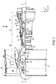
FIG. 1 illustrates a cross-sectional view of an exemplary gas turbine engine, in accordance with various embodiments; -
FIG. 2 illustrates a cross-sectional view of a seal assembly, in accordance with various embodiments; -
FIG. 3 illustrates a cross-sectional view of a seal assembly, in accordance with various embodiments; -
FIG. 4 illustrates a cross-sectional view of a seal assembly, in accordance with various embodiments; -
FIGS. 5A-5D illustrate cross-sectional views of seal assemblies having an additional labyrinth seal configuration, in accordance with various embodiments; and -
FIG. 6 illustrates a schematic flow chart diagram of a method of sealing a bearing system of a gas turbine engine, in accordance with various embodiments. - The subject matter of the present disclosure is particularly pointed out and distinctly claimed in the concluding portion of the specification. A more complete understanding of the present disclosure, however, may best be obtained by referring to the detailed description and claims when considered in connection with the drawing figures.
- The detailed description of exemplary embodiments herein makes reference to the accompanying drawings, which show exemplary embodiments by way of illustration. While these exemplary embodiments are described in sufficient detail to enable those skilled in the art to practice the disclosure, it should be understood that other embodiments may be realized and that logical changes and adaptations in design and construction may be made in accordance with this disclosure and the teachings herein without departing from the spirit and scope of the disclosure. Thus, the detailed description herein is presented for purposes of illustration only and not of limitation.
- As used herein, "aft" refers to the direction associated with the exhaust (e.g., the back end) of a gas turbine engine. As used herein, "forward" refers to the direction associated with the intake (e.g., the front end) of a gas turbine engine.
- A first component that is "axially outward" of a second component means that a first component is positioned at a greater distance in the aft or forward direction away from the longitudinal center of the gas turbine along the longitudinal axis of the gas turbine, than the second component. A first component that is "axially inward" of a second component means that the first component is positioned closer to the longitudinal center of the gas turbine along the longitudinal axis of the gas turbine, than the second component.
- A first component that is "radially outward" of a second component means that the first component is positioned at a greater distance away from the engine central longitudinal axis than the second component. A first component that is "radially inward" of a second component means that the first component is positioned closer to the engine central longitudinal axis than the second component. In the case of components that rotate circumferentially about the engine central longitudinal axis, a first component that is radially inward of a second component rotates through a circumferentially shorter path than the second component. The terminology "radially outward" and "radially inward" may also be used relative to references other than the engine central longitudinal axis. For example, a first component of a combustor that is radially inward or radially outward of a second component of a combustor is positioned relative to the central longitudinal axis of the combustor.
- In various embodiments and with reference to
FIG. 1 , agas turbine engine 20 is provided.Gas turbine engine 20 may be a two-spool turbofan that generally incorporates afan section 22, acompressor section 24, acombustor section 26 and aturbine section 28. Alternative engines may include, for example, an augmentor section among other systems or features. In operation,fan section 22 can drive coolant (e.g., air) along a bypass flow-path B whilecompressor section 24 can drive coolant along a core flow-path C for compression and communication intocombustor section 26 then expansion throughturbine section 28. Although depicted as a turbofangas turbine engine 20 herein, it should be understood that the concepts described herein are not limited to use with turbofans as the teachings may be applied to other types of turbine engines including three-spool architectures. -
Gas turbine engine 20 may generally comprise alow speed spool 30 and ahigh speed spool 32 mounted for rotation about an engine central longitudinal axis A-A' relative to an enginestatic structure 36 or engine case viaseveral bearing systems 38, 38-1, and 38-2. Engine central longitudinal axis A-A' is oriented in the z direction on the provided xyz axis. It should be understood that various bearingsystems 38 at various locations may alternatively or additionally be provided, including for example, bearingsystem 38, bearing system 38-1, and bearing system 38-2. -
Low speed spool 30 may generally comprise aninner shaft 40 that interconnects afan 42, alow pressure compressor 44 and alow pressure turbine 46.Inner shaft 40 may be connected to fan 42 through a gearedarchitecture 48 that can drivefan 42 at a lower speed thanlow speed spool 30.Geared architecture 48 may comprise agear assembly 60 enclosed within agear housing 62.Gear assembly 60 couplesinner shaft 40 to a rotating fan structure.High speed spool 32 may comprise anouter shaft 50 that interconnects ahigh pressure compressor 52 andhigh pressure turbine 54. Acombustor 56 may be located betweenhigh pressure compressor 52 andhigh pressure turbine 54. Amid-turbine frame 57 of enginestatic structure 36 may be located generally betweenhigh pressure turbine 54 andlow pressure turbine 46.Mid-turbine frame 57 may support one ormore bearing systems 38 inturbine section 28.Inner shaft 40 andouter shaft 50 may be concentric and rotate via bearingsystems 38 about the engine central longitudinal axis A-A', which is collinear with their longitudinal axes. As used herein, a "high pressure" compressor or turbine experiences a higher pressure than a corresponding "low pressure" compressor or turbine. - The core airflow C may be compressed by
low pressure compressor 44 thenhigh pressure compressor 52, mixed and burned with fuel incombustor 56, then expanded overhigh pressure turbine 54 andlow pressure turbine 46.Turbines low speed spool 30 andhigh speed spool 32 in response to the expansion. - In various embodiments, geared
architecture 48 may be an epicyclic gear train, such as a star gear system (i.e., a sun gear in meshing engagement with a plurality of star gears supported by a carrier and in meshing engagement with a ring gear) or other gear system.Geared architecture 48 may have a gear reduction ratio of greater than about 2.3 andlow pressure turbine 46 may have a pressure ratio that is greater than about five (5). In various embodiments, the bypass ratio ofgas turbine engine 20 is greater than about ten (10:1). In various embodiments, the diameter offan 42 may be significantly larger than that of thelow pressure compressor 44, and thelow pressure turbine 46 may have a pressure ratio that is greater than about five (5:1).Low pressure turbine 46 pressure ratio may be measured prior to inlet oflow pressure turbine 46 as related to the pressure at the outlet oflow pressure turbine 46 prior to an exhaust nozzle. It should be understood, however, that the above parameters are exemplary of various embodiments of a suitable geared architecture engine and that the present disclosure contemplates other gas turbine engines including direct drive turbofans. A gas turbine engine may comprise an industrial gas turbine (IGT) or a geared aircraft engine, such as a geared turbofan, or non-geared aircraft engine, such as a turbofan, or may comprise any gas turbine engine as desired. - Throughout the present disclosure, like numerals denote like elements. In various embodiments, and with reference to
FIG. 2 , aseal assembly 200 is disclosed herein. Theseal assembly 200 includes, according to various embodiments, afirst seal 210, asecond seal 220, abuffer fluid chamber 230, and abuffer fluid inlet 240. Thefirst seal 210 and thesecond seal 220 are mounted to a housing 250 (e.g., a static housing, such as an engine case or other static structure in the gas turbine engine) and configured to be in sealing engagement with arotatable component 202, in accordance with various embodiments. Therotatable component 202 is configured to rotate about an axis ofrotation 203. Therotatable component 202 may be any of various rotors in thegas turbine engine 20. For example, therotatable component 202 may be a rotating shaft of thelow speed spool 30 or thehigh speed spool 32 discussed above. In various embodiments,rotatable component 202 may be a runner sleeve that is pressed or otherwise fitted to a rotating shaft. Generally, the bearingsystems 38, 38-1, and 38-2 (FIG. 1 ) and theseal assembly 200 described herein are configured to support and interface with therotatable component 202, which, as mentioned above, may be any rotating structure of thegas turbine engine 20. - The
seal assembly 200 may be configured to contain various fluids in respective compartments, regions, or sections of thegas turbine engine 20. For example, abearing compartment 252 of a bearing system may be referred to as a "wet" zone because such a region may be in fluid contact with oil and/or other liquids, such as lubricants, coolants, etc. In various embodiments, thebearing compartment 252 may include a mixture of oil and another fluid, such as air. The mixture of air and oil, for example, may be an air-oil mist. Other regions in thegas turbine engine 20, such asregion 254, may benefit from being oil-free and thus may be referred to as "dry" zones. Theseal assembly 200 of the present disclosure, therefore, is configured to separate thebearing compartment 252 from other areas (e.g., "dry" regions 254), in accordance with various embodiments. That is, theseal assembly 200 may be utilized, for example, to cap the bearing compartment 252 (e.g., sump) for effective oil containment and to preclude hot air ingestion into thebearing compartment 252. The relative orientation of the bearing compartments 252, 254 is not limited to the configuration shown in the figures. That is, in variousembodiments bearing compartment 252 may be the "dry" zone andbearing compartment 254 may be the "wet" zone. - In various embodiments, the
first seal 210 and thesecond seal 220 are brush seals. Accordingly, in various embodiments, the first andsecond seals seals rotatable component 202, or at least the region/surface of therotatable component 202 to which theseals - The
first seal 210 and thesecond seal 220 may be spaced an axial distance apart from each other. That is, thefirst seal 210 and thesecond seal 220 are not in direct juxtaposed contact with each other but instead are disposed so there is an axial gap or an axial distance, parallel with the axis ofrotation 203, between the twoseals seals buffer fluid chamber 230. Thebuffer fluid chamber 230 is defined by the twoseals spacer 215 may be disposed in thebuffer fluid chamber 230 to support theseals spacer 215 may include holes, slots, apertures, or other passageways to allow buffer air to pressurize thebuffer fluid chamber 230. - In various embodiments, the two
seals housing 250. For example, one or more retaining devices/elements 245 may be mounted to or received into thestatic housing 250. The retainingelement 245 may securely retain theseals housing 250. In various embodiments, the retainingelement 245 may include one or more retaining rings, wires, nut(s), bolts, etc. In various embodiments, theseal assembly 200 may include aspacer 215 that is disposed in thebuffer fluid chamber 230 and that is configured to, in conjunction with the one ormore retaining elements 245, mechanically retain theseals static housing 250. - In various embodiments, the
seal assembly 200 includes one or morebuffer fluid inlets 240 that are in fluid providing communication with thebuffer fluid chamber 230. Said differently, a buffer fluid is configured to flow through the one or morebuffer fluid inlets 240 and into thebuffer fluid chamber 230. In various embodiments, the buffer fluid may be air or a combustion gas. In various embodiments, and with reference toFIG. 2 , thebuffer fluid inlet 240 may be formed in or extend through one or more walls of thehousing 250. That is, the buffer fluid may be delivered from a radially outward source and may be configured to move radially inward through the one or more walls of thehousing 250 to enter thebuffer fluid chamber 230. In various embodiments, and with reference to theseal assembly 300 ofFIG. 3 , thebuffer fluid inlet 340 may be formed in or extend through one or more walls of therotatable component 302. That is, the buffer fluid may be delivered from a radially inward source and may be configured to move radially outward through the one or more walls of therotatable component 302 to enter thebuffer fluid chamber 230. In various embodiments, the seal assembly may include a buffer fluid inlet disposed in both the housing (e.g., 250 ofFIG. 2 ) and the rotatable component (e.g., 302 ofFIG 3 ). - The
buffer fluid chamber 230 may be maintained, via delivery of buffer fluid through the one or morebuffer fluid inlets 240/340, at a higher pressure than the "dry"region 254 and thebearing compartment 252. Accordingly, thebuffer fluid chamber 230 may be configured to facilitate containment of the oil within thebearing compartment 252 and may prevent ingestion of air and/or other gases into thebearing compartment 252. In various embodiments, theseal assembly 200 of the present disclosure does not contribute significantly to limiting rotor speed, tends to have little to no oil cooling needs, is compact in size, and facilitates the maintenance of a stable and/or robust pressure difference between "wet" and "dry" zones of thegas turbine engine 20. - In various embodiments, the seal assembly may include multiple buffer fluid inlets. In various embodiments, and with reference to
FIG. 4 , theseal assembly 400 may have an annular structure that circumscribes the axis ofrotation 203. Accordingly, the cross-sectional view of theseal assembly 400 ofFIG. 4 shows atop portion 405 and abottom portion 406 of theseal assembly 400. The terms "top" and "bottom" may be relative to, for example, a standard orientation of thegas turbine engine 20. Thus, thebottom portion 406 of theseal assembly 400 may be the lowermost portion of theseal assembly 400 when an aircraft having thegas turbine engine 20 is in a horizontal orientation. Multiplebuffer fluid inlets housing 450 at various circumferential locations of thehousing 450. Eachbuffer fluid inlet - In various embodiments, the
seal assembly 400 may include apassage 451 disposed in thebottom portion 406 of thehousing 450 that is configured to return any leaked oil back into thebearing compartment 252 or the oil may be routed to a benign area of the gas turbine engine via drain tubes and/or drain passages. That is, in the event that any oil or other liquid leaks past thesecond seal 220 into thebuffer fluid chamber 230, such leaked oil may drain to the lowermost section of theseal assembly 400 and may be flow through thepassage 451 back into thebearing compartment 252. - In various embodiments, and with reference to
FIGS 5A-5D , theseal assembly seal assembly assembly configuration FIGS. 5A and 5B , respectively). In various embodiments, theseal assembly straight configuration 580C, 580D (FIGS. 5C and 5D , respectively). In various embodiments, the knife edges of theseal assembly straight orientation 580A, 580C (FIGS. 5A and 5C , respectively). In various embodiments, the knife edges of theseal assembly orientation FIGS. 5B and 5D , respectively). - In various embodiments, and with reference to
FIG. 6 , amethod 690 of sealing a bearing system of a gas turbine engine is disclosed. Themethod 690 includes, according to various embodiments, retaining a first brush seal an axial distance apart from a second brush seal atstep 692. Themethod 690, according to various embodiments, further includes flowing a buffer fluid into a buffer fluid chamber defined between the first brush seal and the second brush seal atstep 694. - Benefits, other advantages, and solutions to problems have been described herein with regard to specific embodiments. Furthermore, the connecting lines shown in the various figures contained herein are intended to represent exemplary functional relationships and/or physical couplings between the various elements. It should be noted that many alternative or additional functional relationships or physical connections may be present in a practical system. However, the benefits, advantages, solutions to problems, and any elements that may cause any benefit, advantage, or solution to occur or become more pronounced are not to be construed as critical, required, or essential features or elements of the disclosure.
- The scope of the disclosure is accordingly to be limited by nothing other than the appended claims, in which reference to an element in the singular is not intended to mean "one and only one" unless explicitly so stated, but rather "one or more." It is to be understood that unless specifically stated otherwise, references to "a," "an," and/or "the" may include one or more than one and that reference to an item in the singular may also include the item in the plural. All ranges and ratio limits disclosed herein may be combined.
- Moreover, where a phrase similar to "at least one of A, B, and C" is used in the claims, it is intended that the phrase be interpreted to mean that A alone may be present in an embodiment, B alone may be present in an embodiment, C alone may be present in an embodiment, or that any combination of the elements A, B and C may be present in a single embodiment; for example, A and B, A and C, B and C, or A and B and C. Different cross-hatching is used throughout the figures to denote different parts but not necessarily to denote the same or different materials.
- The steps recited in any of the method or process descriptions may be executed in any order and are not necessarily limited to the order presented. Furthermore, any reference to singular includes plural embodiments, and any reference to more than one component or step may include a singular embodiment or step. Elements and steps in the figures are illustrated for simplicity and clarity and have not necessarily been rendered according to any particular sequence. For example, steps that may be performed concurrently or in different order are illustrated in the figures to help to improve understanding of embodiments of the present disclosure.
- Any reference to attached, fixed, connected or the like may include permanent, removable, temporary, partial, full and/or any other possible attachment option. Additionally, any reference to without contact (or similar phrases) may also include reduced contact or minimal contact. Surface shading lines may be used throughout the figures to denote different parts or areas but not necessarily to denote the same or different materials. In some cases, reference coordinates may be specific to each figure.
- Systems, methods and apparatus are provided herein. In the detailed description herein, references to "one embodiment", "an embodiment", "various embodiments", etc., indicate that the embodiment described may include a particular feature, structure, or characteristic, but every embodiment may not necessarily include the particular feature, structure, or characteristic. Moreover, such phrases are not necessarily referring to the same embodiment. Further, when a particular feature, structure, or characteristic is described in connection with an embodiment, it is submitted that it is within the knowledge of one skilled in the art to affect such feature, structure, or characteristic in connection with other embodiments whether or not explicitly described. After reading the description, it will be apparent to one skilled in the relevant art(s) how to implement the disclosure in alternative embodiments.
- Furthermore, no element, component, or method step in the present disclosure is intended to be dedicated to the public regardless of whether the element, component, or method step is explicitly recited in the claims. No claim element is intended to invoke 35 U.S.C. 112(f) unless the element is expressly recited using the phrase "means for." As used herein, the terms "comprises", "comprising", or any other variation thereof, are intended to cover a non-exclusive inclusion, such that a process, method, article, or apparatus that comprises a list of elements does not include only those elements but may include other elements not expressly listed or inherent to such process, method, article, or apparatus.
Claims (15)
- A seal assembly for a rotatable component having an axis of rotation, the seal assembly comprising:a first seal mounted to a housing and configured to be in sealing engagement with the rotatable component;a second seal mounted to the housing an axial distance apart from the first seal and configured to be in sealing engagement with the rotatable component, wherein the axial distance is parallel with the axis of rotation;a buffer fluid chamber defined between the first seal and the second seal; anda buffer fluid inlet in fluid providing communication with the buffer fluid chamber.
- The seal assembly of claim 1, wherein the first seal is a first brush seal and the second seal is a second brush seal.
- The seal assembly of claim 1 or 2, wherein the first seal is configured to separate a gas from a buffer fluid in the buffer fluid chamber.
- The seal assembly of claim 3, wherein the second seal is configured to separate the buffer fluid in the buffer fluid chamber from oil, or wherein the second seal is configured to separate the buffer fluid in the buffer fluid chamber from an oil mist.
- The seal assembly of any preceding claim, wherein the first seal and the second seal are mechanically retained to the housing, optionally further comprising a spacer disposed between the first seal and the second seal.
- The seal assembly of any preceding claim, wherein the first seal and the second seal extend radially and thus perpendicularly to the axis of rotation.
- A seal assembly of a bearing system of a gas turbine engine, the seal assembly comprising:a rotatable component having an axis of rotation;a static housing;a first seal mounted to the static housing in sealing engagement with the rotatable component;a second seal mounted to the static housing an axial distance apart from the first seal in sealing engagement with the rotatable component, wherein the axial distance is parallel with the axis of rotation;a buffer fluid chamber defined between the first seal and the second seal; anda buffer fluid inlet in fluid providing communication with the buffer fluid chamber,wherein the buffer fluid inlet is configured to deliver buffer fluid through at least one of a wall of the static housing and a wall of the rotatable component.
- The seal assembly of claim 7, wherein the first seal is a first brush seal and the second seal is a second brush seal.
- The seal assembly of claim 8, wherein the first brush seal is configured to separate a gas from a buffer fluid in the buffer fluid chamber.
- The seal assembly of claim 9, wherein the second brush seal is configured to separate the buffer fluid in the buffer fluid chamber from oil in a bearing compartment of the gas turbine engine.
- The seal assembly of claim 9, wherein the second brush seal is configured to separate the buffer fluid in the buffer fluid chamber from an oil mist in a bearing compartment of the gas turbine engine.
- The seal assembly of claim 10 or 11, wherein the static housing has an annular structure that is concentric with the axis of rotation, wherein optionally the static housing comprises a passage in a bottom portion of the annular structure configured to allow oil leaking through the second brush seal from the bearing compartment into the buffer fluid chamber to drain into the bearing compartment.
- The seal assembly of any of claims 7 to 12, further comprising at least one labyrinth seal configuration.
- The seal assembly of claim 13, wherein the labyrinth seal configuration is a stepped configuration, or wherein the labyrinth seal configuration is a straight configuration, and/or wherein optionally the labyrinth seal configuration comprises at least one canted knife edge.
- A method of sealing a bearing system of a gas turbine engine, the method comprising:retaining a first brush seal an axial distance apart from a second brush seal; andflowing a buffer fluid into a buffer fluid chamber defined between the first brush seal and the second brush seal.
Applications Claiming Priority (1)
| Application Number | Priority Date | Filing Date | Title |
|---|---|---|---|
| US15/342,886 US10557359B2 (en) | 2016-11-03 | 2016-11-03 | Seal assembly |
Publications (2)
| Publication Number | Publication Date |
|---|---|
| EP3318722A1 true EP3318722A1 (en) | 2018-05-09 |
| EP3318722B1 EP3318722B1 (en) | 2021-08-25 |
Family
ID=60021979
Family Applications (1)
| Application Number | Title | Priority Date | Filing Date |
|---|---|---|---|
| EP17194916.7A Active EP3318722B1 (en) | 2016-11-03 | 2017-10-05 | Seal assembly for a rotatable component |
Country Status (2)
| Country | Link |
|---|---|
| US (1) | US10557359B2 (en) |
| EP (1) | EP3318722B1 (en) |
Cited By (3)
| Publication number | Priority date | Publication date | Assignee | Title |
|---|---|---|---|---|
| FR3089546A1 (en) * | 2018-12-06 | 2020-06-12 | Safran Aircraft Engines | Improved bearing support |
| WO2021148077A1 (en) * | 2020-01-21 | 2021-07-29 | MTU Aero Engines AG | Sealing device for a sealing-air apparatus of a turbomachine, and associated repair method |
| EP3293360B1 (en) * | 2016-09-13 | 2025-10-29 | RTX Corporation | Seal system with primary and secondary seal arrangement |
Families Citing this family (6)
| Publication number | Priority date | Publication date | Assignee | Title |
|---|---|---|---|---|
| FR3075861B1 (en) * | 2017-12-22 | 2019-11-15 | Safran Aircraft Engines | DYNAMIC SEAL BETWEEN TWO ROTORS OF AN AIRCRAFT TURBOMACHINE |
| US12595747B2 (en) * | 2023-07-20 | 2026-04-07 | Pratt & Whitney Canada Corp. | Method of mitigating vibrations in a seal component |
| US12320297B2 (en) | 2023-10-17 | 2025-06-03 | Pratt & Whitney Canada Corp. | Aircraft power system module with integral lubricant reservoir |
| US12416264B2 (en) | 2023-10-17 | 2025-09-16 | Pratt & Whitney Canada Corp. | Lubrication system for aircraft powerplant and clutch system |
| US20250129750A1 (en) * | 2023-10-19 | 2025-04-24 | Pratt & Whitney Canada Corp. | Double seal element seal assembly for aircraft system |
| US12516609B2 (en) * | 2024-06-14 | 2026-01-06 | Pratt & Whitney Canada Corp. | Serviceable propeller shaft zero air gap seal |
Citations (5)
| Publication number | Priority date | Publication date | Assignee | Title |
|---|---|---|---|---|
| US20080001364A1 (en) * | 2004-03-16 | 2008-01-03 | Anderson James H | Bearing seal with backup device |
| US20080008574A1 (en) * | 2006-07-07 | 2008-01-10 | Siemens Power Generation, Inc. | Leakage flow control and seal wear minimization system for a turbine engine |
| US20120328418A1 (en) * | 2011-06-24 | 2012-12-27 | Caterpillar Inc. | Turbocharger with air buffer seal |
| US20140035238A1 (en) * | 2009-11-30 | 2014-02-06 | Kalsi Engineering, Inc. | Dynamic backup ring assembly |
| EP3048344A2 (en) * | 2015-01-21 | 2016-07-27 | United Technologies Corporation | Seal housing pre-taper |
Family Cites Families (11)
| Publication number | Priority date | Publication date | Assignee | Title |
|---|---|---|---|---|
| US5749584A (en) | 1992-11-19 | 1998-05-12 | General Electric Company | Combined brush seal and labyrinth seal segment for rotary machines |
| US6131910A (en) | 1992-11-19 | 2000-10-17 | General Electric Co. | Brush seals and combined labyrinth and brush seals for rotary machines |
| US6027121A (en) * | 1997-10-23 | 2000-02-22 | General Electric Co. | Combined brush/labyrinth seal for rotary machines |
| US6428009B2 (en) | 2000-04-03 | 2002-08-06 | John F. Justak | Robust hydrodynamic brush seal |
| GB2366842A (en) * | 2000-09-09 | 2002-03-20 | Rolls Royce Plc | A bearing chamber sealing system |
| US6502824B2 (en) | 2000-12-15 | 2003-01-07 | General Electric Company | Brush seal for a bearing cavity |
| US20040217549A1 (en) | 2003-05-01 | 2004-11-04 | Justak John F. | Hydrodynamic brush seal |
| US7093418B2 (en) * | 2004-04-21 | 2006-08-22 | Honeywell International, Inc. | Gas turbine engine including a low pressure sump seal buffer source and thermally isolated sump |
| GB0412476D0 (en) * | 2004-06-04 | 2004-07-07 | Rolls Royce Plc | Seal system |
| US7854584B2 (en) * | 2007-05-24 | 2010-12-21 | General Electric Company | Barrier sealing system for centrifugal compressors |
| KR101695125B1 (en) | 2016-01-11 | 2017-01-10 | 두산중공업 주식회사 | Structure for a multi-stage sealing of a turbine |
-
2016
- 2016-11-03 US US15/342,886 patent/US10557359B2/en active Active
-
2017
- 2017-10-05 EP EP17194916.7A patent/EP3318722B1/en active Active
Patent Citations (5)
| Publication number | Priority date | Publication date | Assignee | Title |
|---|---|---|---|---|
| US20080001364A1 (en) * | 2004-03-16 | 2008-01-03 | Anderson James H | Bearing seal with backup device |
| US20080008574A1 (en) * | 2006-07-07 | 2008-01-10 | Siemens Power Generation, Inc. | Leakage flow control and seal wear minimization system for a turbine engine |
| US20140035238A1 (en) * | 2009-11-30 | 2014-02-06 | Kalsi Engineering, Inc. | Dynamic backup ring assembly |
| US20120328418A1 (en) * | 2011-06-24 | 2012-12-27 | Caterpillar Inc. | Turbocharger with air buffer seal |
| EP3048344A2 (en) * | 2015-01-21 | 2016-07-27 | United Technologies Corporation | Seal housing pre-taper |
Cited By (3)
| Publication number | Priority date | Publication date | Assignee | Title |
|---|---|---|---|---|
| EP3293360B1 (en) * | 2016-09-13 | 2025-10-29 | RTX Corporation | Seal system with primary and secondary seal arrangement |
| FR3089546A1 (en) * | 2018-12-06 | 2020-06-12 | Safran Aircraft Engines | Improved bearing support |
| WO2021148077A1 (en) * | 2020-01-21 | 2021-07-29 | MTU Aero Engines AG | Sealing device for a sealing-air apparatus of a turbomachine, and associated repair method |
Also Published As
| Publication number | Publication date |
|---|---|
| US10557359B2 (en) | 2020-02-11 |
| EP3318722B1 (en) | 2021-08-25 |
| US20180119557A1 (en) | 2018-05-03 |
Similar Documents
| Publication | Publication Date | Title |
|---|---|---|
| US10557359B2 (en) | Seal assembly | |
| EP2809908B1 (en) | Mid-turbine frame buffer system | |
| US10087847B2 (en) | Seal assembly for a static structure of a gas turbine engine | |
| EP2964935B1 (en) | Fluid-cooled seal arrangement for a gas turbine engine | |
| US9574459B2 (en) | Non-contacting seals for geared gas turbine engine bearing compartments | |
| US10385710B2 (en) | Multiwall tube and fitting for bearing oil supply | |
| US9546560B2 (en) | Compact double grounded mechanical carbon seal | |
| US9896969B2 (en) | Zero or low leakage oil transfer bearing | |
| US10648365B2 (en) | Gas turbine engine bearing sump and lubricant drain line from cooling passage | |
| US10934845B2 (en) | Dual cooling airflow to blades | |
| US10329951B2 (en) | Sealing configurations with active cooling features | |
| EP3293360B1 (en) | Seal system with primary and secondary seal arrangement | |
| US20240352942A1 (en) | Tandem blade rotor disk | |
| US9752446B2 (en) | Support buttress | |
| US11215056B2 (en) | Thermally isolated rotor systems and methods | |
| US9803496B2 (en) | Break-in system for gapping and leakage control | |
| EP3249176B1 (en) | Dirt shield |
Legal Events
| Date | Code | Title | Description |
|---|---|---|---|
| PUAI | Public reference made under article 153(3) epc to a published international application that has entered the european phase |
Free format text: ORIGINAL CODE: 0009012 |
|
| STAA | Information on the status of an ep patent application or granted ep patent |
Free format text: STATUS: THE APPLICATION HAS BEEN PUBLISHED |
|
| AK | Designated contracting states |
Kind code of ref document: A1 Designated state(s): AL AT BE BG CH CY CZ DE DK EE ES FI FR GB GR HR HU IE IS IT LI LT LU LV MC MK MT NL NO PL PT RO RS SE SI SK SM TR |
|
| AX | Request for extension of the european patent |
Extension state: BA ME |
|
| STAA | Information on the status of an ep patent application or granted ep patent |
Free format text: STATUS: REQUEST FOR EXAMINATION WAS MADE |
|
| 17P | Request for examination filed |
Effective date: 20181107 |
|
| RBV | Designated contracting states (corrected) |
Designated state(s): AL AT BE BG CH CY CZ DE DK EE ES FI FR GB GR HR HU IE IS IT LI LT LU LV MC MK MT NL NO PL PT RO RS SE SI SK SM TR |
|
| STAA | Information on the status of an ep patent application or granted ep patent |
Free format text: STATUS: EXAMINATION IS IN PROGRESS |
|
| 17Q | First examination report despatched |
Effective date: 20190304 |
|
| RAP1 | Party data changed (applicant data changed or rights of an application transferred) |
Owner name: RAYTHEON TECHNOLOGIES CORPORATION |
|
| GRAP | Despatch of communication of intention to grant a patent |
Free format text: ORIGINAL CODE: EPIDOSNIGR1 |
|
| STAA | Information on the status of an ep patent application or granted ep patent |
Free format text: STATUS: GRANT OF PATENT IS INTENDED |
|
| INTG | Intention to grant announced |
Effective date: 20210331 |
|
| GRAS | Grant fee paid |
Free format text: ORIGINAL CODE: EPIDOSNIGR3 |
|
| GRAA | (expected) grant |
Free format text: ORIGINAL CODE: 0009210 |
|
| STAA | Information on the status of an ep patent application or granted ep patent |
Free format text: STATUS: THE PATENT HAS BEEN GRANTED |
|
| AK | Designated contracting states |
Kind code of ref document: B1 Designated state(s): AL AT BE BG CH CY CZ DE DK EE ES FI FR GB GR HR HU IE IS IT LI LT LU LV MC MK MT NL NO PL PT RO RS SE SI SK SM TR |
|
| REG | Reference to a national code |
Ref country code: CH Ref legal event code: EP |
|
| REG | Reference to a national code |
Ref country code: IE Ref legal event code: FG4D Ref country code: AT Ref legal event code: REF Ref document number: 1423992 Country of ref document: AT Kind code of ref document: T Effective date: 20210915 |
|
| REG | Reference to a national code |
Ref country code: DE Ref legal event code: R096 Ref document number: 602017044614 Country of ref document: DE |
|
| REG | Reference to a national code |
Ref country code: LT Ref legal event code: MG9D |
|
| REG | Reference to a national code |
Ref country code: NL Ref legal event code: MP Effective date: 20210825 |
|
| REG | Reference to a national code |
Ref country code: AT Ref legal event code: MK05 Ref document number: 1423992 Country of ref document: AT Kind code of ref document: T Effective date: 20210825 |
|
| PG25 | Lapsed in a contracting state [announced via postgrant information from national office to epo] |
Ref country code: SE Free format text: LAPSE BECAUSE OF FAILURE TO SUBMIT A TRANSLATION OF THE DESCRIPTION OR TO PAY THE FEE WITHIN THE PRESCRIBED TIME-LIMIT Effective date: 20210825 Ref country code: RS Free format text: LAPSE BECAUSE OF FAILURE TO SUBMIT A TRANSLATION OF THE DESCRIPTION OR TO PAY THE FEE WITHIN THE PRESCRIBED TIME-LIMIT Effective date: 20210825 Ref country code: HR Free format text: LAPSE BECAUSE OF FAILURE TO SUBMIT A TRANSLATION OF THE DESCRIPTION OR TO PAY THE FEE WITHIN THE PRESCRIBED TIME-LIMIT Effective date: 20210825 Ref country code: AT Free format text: LAPSE BECAUSE OF FAILURE TO SUBMIT A TRANSLATION OF THE DESCRIPTION OR TO PAY THE FEE WITHIN THE PRESCRIBED TIME-LIMIT Effective date: 20210825 Ref country code: BG Free format text: LAPSE BECAUSE OF FAILURE TO SUBMIT A TRANSLATION OF THE DESCRIPTION OR TO PAY THE FEE WITHIN THE PRESCRIBED TIME-LIMIT Effective date: 20211125 Ref country code: LT Free format text: LAPSE BECAUSE OF FAILURE TO SUBMIT A TRANSLATION OF THE DESCRIPTION OR TO PAY THE FEE WITHIN THE PRESCRIBED TIME-LIMIT Effective date: 20210825 Ref country code: PT Free format text: LAPSE BECAUSE OF FAILURE TO SUBMIT A TRANSLATION OF THE DESCRIPTION OR TO PAY THE FEE WITHIN THE PRESCRIBED TIME-LIMIT Effective date: 20211227 Ref country code: NO Free format text: LAPSE BECAUSE OF FAILURE TO SUBMIT A TRANSLATION OF THE DESCRIPTION OR TO PAY THE FEE WITHIN THE PRESCRIBED TIME-LIMIT Effective date: 20211125 Ref country code: FI Free format text: LAPSE BECAUSE OF FAILURE TO SUBMIT A TRANSLATION OF THE DESCRIPTION OR TO PAY THE FEE WITHIN THE PRESCRIBED TIME-LIMIT Effective date: 20210825 Ref country code: ES Free format text: LAPSE BECAUSE OF FAILURE TO SUBMIT A TRANSLATION OF THE DESCRIPTION OR TO PAY THE FEE WITHIN THE PRESCRIBED TIME-LIMIT Effective date: 20210825 |
|
| PG25 | Lapsed in a contracting state [announced via postgrant information from national office to epo] |
Ref country code: PL Free format text: LAPSE BECAUSE OF FAILURE TO SUBMIT A TRANSLATION OF THE DESCRIPTION OR TO PAY THE FEE WITHIN THE PRESCRIBED TIME-LIMIT Effective date: 20210825 Ref country code: LV Free format text: LAPSE BECAUSE OF FAILURE TO SUBMIT A TRANSLATION OF THE DESCRIPTION OR TO PAY THE FEE WITHIN THE PRESCRIBED TIME-LIMIT Effective date: 20210825 Ref country code: GR Free format text: LAPSE BECAUSE OF FAILURE TO SUBMIT A TRANSLATION OF THE DESCRIPTION OR TO PAY THE FEE WITHIN THE PRESCRIBED TIME-LIMIT Effective date: 20211126 |
|
| PG25 | Lapsed in a contracting state [announced via postgrant information from national office to epo] |
Ref country code: NL Free format text: LAPSE BECAUSE OF FAILURE TO SUBMIT A TRANSLATION OF THE DESCRIPTION OR TO PAY THE FEE WITHIN THE PRESCRIBED TIME-LIMIT Effective date: 20210825 |
|
| PG25 | Lapsed in a contracting state [announced via postgrant information from national office to epo] |
Ref country code: DK Free format text: LAPSE BECAUSE OF FAILURE TO SUBMIT A TRANSLATION OF THE DESCRIPTION OR TO PAY THE FEE WITHIN THE PRESCRIBED TIME-LIMIT Effective date: 20210825 |
|
| REG | Reference to a national code |
Ref country code: DE Ref legal event code: R097 Ref document number: 602017044614 Country of ref document: DE |
|
| PG25 | Lapsed in a contracting state [announced via postgrant information from national office to epo] |
Ref country code: SM Free format text: LAPSE BECAUSE OF FAILURE TO SUBMIT A TRANSLATION OF THE DESCRIPTION OR TO PAY THE FEE WITHIN THE PRESCRIBED TIME-LIMIT Effective date: 20210825 Ref country code: SK Free format text: LAPSE BECAUSE OF FAILURE TO SUBMIT A TRANSLATION OF THE DESCRIPTION OR TO PAY THE FEE WITHIN THE PRESCRIBED TIME-LIMIT Effective date: 20210825 Ref country code: RO Free format text: LAPSE BECAUSE OF FAILURE TO SUBMIT A TRANSLATION OF THE DESCRIPTION OR TO PAY THE FEE WITHIN THE PRESCRIBED TIME-LIMIT Effective date: 20210825 Ref country code: EE Free format text: LAPSE BECAUSE OF FAILURE TO SUBMIT A TRANSLATION OF THE DESCRIPTION OR TO PAY THE FEE WITHIN THE PRESCRIBED TIME-LIMIT Effective date: 20210825 Ref country code: CZ Free format text: LAPSE BECAUSE OF FAILURE TO SUBMIT A TRANSLATION OF THE DESCRIPTION OR TO PAY THE FEE WITHIN THE PRESCRIBED TIME-LIMIT Effective date: 20210825 Ref country code: AL Free format text: LAPSE BECAUSE OF FAILURE TO SUBMIT A TRANSLATION OF THE DESCRIPTION OR TO PAY THE FEE WITHIN THE PRESCRIBED TIME-LIMIT Effective date: 20210825 |
|
| REG | Reference to a national code |
Ref country code: CH Ref legal event code: PL |
|
| REG | Reference to a national code |
Ref country code: BE Ref legal event code: MM Effective date: 20211031 |
|
| PG25 | Lapsed in a contracting state [announced via postgrant information from national office to epo] |
Ref country code: MC Free format text: LAPSE BECAUSE OF FAILURE TO SUBMIT A TRANSLATION OF THE DESCRIPTION OR TO PAY THE FEE WITHIN THE PRESCRIBED TIME-LIMIT Effective date: 20210825 |
|
| PLBE | No opposition filed within time limit |
Free format text: ORIGINAL CODE: 0009261 |
|
| STAA | Information on the status of an ep patent application or granted ep patent |
Free format text: STATUS: NO OPPOSITION FILED WITHIN TIME LIMIT |
|
| PG25 | Lapsed in a contracting state [announced via postgrant information from national office to epo] |
Ref country code: LU Free format text: LAPSE BECAUSE OF NON-PAYMENT OF DUE FEES Effective date: 20211005 Ref country code: IT Free format text: LAPSE BECAUSE OF FAILURE TO SUBMIT A TRANSLATION OF THE DESCRIPTION OR TO PAY THE FEE WITHIN THE PRESCRIBED TIME-LIMIT Effective date: 20210825 Ref country code: BE Free format text: LAPSE BECAUSE OF NON-PAYMENT OF DUE FEES Effective date: 20211031 |
|
| 26N | No opposition filed |
Effective date: 20220527 |
|
| PG25 | Lapsed in a contracting state [announced via postgrant information from national office to epo] |
Ref country code: SI Free format text: LAPSE BECAUSE OF FAILURE TO SUBMIT A TRANSLATION OF THE DESCRIPTION OR TO PAY THE FEE WITHIN THE PRESCRIBED TIME-LIMIT Effective date: 20210825 Ref country code: LI Free format text: LAPSE BECAUSE OF NON-PAYMENT OF DUE FEES Effective date: 20211031 Ref country code: CH Free format text: LAPSE BECAUSE OF NON-PAYMENT OF DUE FEES Effective date: 20211031 |
|
| PG25 | Lapsed in a contracting state [announced via postgrant information from national office to epo] |
Ref country code: IE Free format text: LAPSE BECAUSE OF NON-PAYMENT OF DUE FEES Effective date: 20211005 |
|
| PG25 | Lapsed in a contracting state [announced via postgrant information from national office to epo] |
Ref country code: HU Free format text: LAPSE BECAUSE OF FAILURE TO SUBMIT A TRANSLATION OF THE DESCRIPTION OR TO PAY THE FEE WITHIN THE PRESCRIBED TIME-LIMIT; INVALID AB INITIO Effective date: 20171005 |
|
| P01 | Opt-out of the competence of the unified patent court (upc) registered |
Effective date: 20230520 |
|
| PG25 | Lapsed in a contracting state [announced via postgrant information from national office to epo] |
Ref country code: CY Free format text: LAPSE BECAUSE OF FAILURE TO SUBMIT A TRANSLATION OF THE DESCRIPTION OR TO PAY THE FEE WITHIN THE PRESCRIBED TIME-LIMIT Effective date: 20210825 |
|
| PG25 | Lapsed in a contracting state [announced via postgrant information from national office to epo] |
Ref country code: MK Free format text: LAPSE BECAUSE OF FAILURE TO SUBMIT A TRANSLATION OF THE DESCRIPTION OR TO PAY THE FEE WITHIN THE PRESCRIBED TIME-LIMIT Effective date: 20210825 |
|
| PG25 | Lapsed in a contracting state [announced via postgrant information from national office to epo] |
Ref country code: TR Free format text: LAPSE BECAUSE OF FAILURE TO SUBMIT A TRANSLATION OF THE DESCRIPTION OR TO PAY THE FEE WITHIN THE PRESCRIBED TIME-LIMIT Effective date: 20210825 |
|
| PG25 | Lapsed in a contracting state [announced via postgrant information from national office to epo] |
Ref country code: MT Free format text: LAPSE BECAUSE OF FAILURE TO SUBMIT A TRANSLATION OF THE DESCRIPTION OR TO PAY THE FEE WITHIN THE PRESCRIBED TIME-LIMIT Effective date: 20210825 |
|
| REG | Reference to a national code |
Ref country code: DE Ref legal event code: R081 Ref document number: 602017044614 Country of ref document: DE Owner name: RTX CORPORATION (N.D.GES.D. STAATES DELAWARE),, US Free format text: FORMER OWNER: RAYTHEON TECHNOLOGIES CORPORATION, FARMINGTON, CT, US |
|
| PGFP | Annual fee paid to national office [announced via postgrant information from national office to epo] |
Ref country code: GB Payment date: 20250923 Year of fee payment: 9 |
|
| PGFP | Annual fee paid to national office [announced via postgrant information from national office to epo] |
Ref country code: FR Payment date: 20250925 Year of fee payment: 9 |
|
| PGFP | Annual fee paid to national office [announced via postgrant information from national office to epo] |
Ref country code: DE Payment date: 20250923 Year of fee payment: 9 |