EP3318679A1 - Control system for a loader of a work vehicle - Google Patents
Control system for a loader of a work vehicle Download PDFInfo
- Publication number
- EP3318679A1 EP3318679A1 EP17199390.0A EP17199390A EP3318679A1 EP 3318679 A1 EP3318679 A1 EP 3318679A1 EP 17199390 A EP17199390 A EP 17199390A EP 3318679 A1 EP3318679 A1 EP 3318679A1
- Authority
- EP
- European Patent Office
- Prior art keywords
- valve
- bucket
- lifting
- control
- valves
- Prior art date
- Legal status (The legal status is an assumption and is not a legal conclusion. Google has not performed a legal analysis and makes no representation as to the accuracy of the status listed.)
- Granted
Links
Images

Classifications
-
- E—FIXED CONSTRUCTIONS
- E02—HYDRAULIC ENGINEERING; FOUNDATIONS; SOIL SHIFTING
- E02F—DREDGING; SOIL-SHIFTING
- E02F3/00—Dredgers; Soil-shifting machines
- E02F3/04—Dredgers; Soil-shifting machines mechanically-driven
- E02F3/28—Dredgers; Soil-shifting machines mechanically-driven with digging tools mounted on a dipper- or bucket-arm, i.e. there is either one arm or a pair of arms, e.g. dippers, buckets
- E02F3/36—Component parts
- E02F3/42—Drives for dippers, buckets, dipper-arms or bucket-arms
- E02F3/422—Drive systems for bucket-arms, front-end loaders, dumpers or the like
-
- E—FIXED CONSTRUCTIONS
- E02—HYDRAULIC ENGINEERING; FOUNDATIONS; SOIL SHIFTING
- E02F—DREDGING; SOIL-SHIFTING
- E02F9/00—Component parts of dredgers or soil-shifting machines, not restricted to one of the kinds covered by groups E02F3/00 - E02F7/00
- E02F9/20—Drives; Control devices
- E02F9/22—Hydraulic or pneumatic drives
- E02F9/2221—Control of flow rate; Load sensing arrangements
-
- E—FIXED CONSTRUCTIONS
- E02—HYDRAULIC ENGINEERING; FOUNDATIONS; SOIL SHIFTING
- E02F—DREDGING; SOIL-SHIFTING
- E02F9/00—Component parts of dredgers or soil-shifting machines, not restricted to one of the kinds covered by groups E02F3/00 - E02F7/00
- E02F9/20—Drives; Control devices
- E02F9/22—Hydraulic or pneumatic drives
- E02F9/2278—Hydraulic circuits
- E02F9/2282—Systems using center bypass type changeover valves
Definitions
- the present invention relates to a control system applicable to a loader of a work vehicle, such as a tractor and, more specifically, the invention related to a hydraulic control system applicable to a loader of a work vehicle, in which valves arrangement and control logic enable the control of the elevation of the loader and of the bucket efficiently.
- the term "tractor” may be used to designate a large scale of vehicles, from those that effectively drive an implement or additional machine, until those that perform specific activities in an individual manner (generally, heavy work).
- its loader comprises a lifting mechanism (usually consisting of articulated arms or similar with hydraulic cylinders) and a mechanism to control the bucket (usually comprising a pivotable construction also with a hydraulic cylinder).
- Both the lifting and bucket control mechanisms are controlled through a logic of hydraulics, which uses a set of valves in order to direct the fluid towards each mechanism according to the operator's action.
- a first system uses an arrangement of valves in series in order to feed the mechanisms, in a way that the fluid pressure is concentrated in a single line.
- This system in series requires a small amount of fluid outflow to control both mechanisms, due to a certain velocity of operation, in a way that the work of a system with an arrangement of valves in series is performed rapidly.
- the control system with an arrangement in series works with a substantially high pressure, since it demands the feeding of two mechanisms through a single line.
- the feeding pressure must be a sum of the required pressures for handling each mechanism, which drastically reduces the maximum load tolerated for a system of this type when both mechanisms work at the same time.
- control system with an arrangement in series has the disadvantage of loss of maximum load in situations where the lifting and bucket control mechanisms are simultaneously operated.
- a second type of control uses an arrangement of valves in parallel, in a way that both system mechanisms are controlled from parallel feeding lines.
- the feeding pressure is distributed to the lines of each mechanism, drastically reducing the amount of pressure demanded by the system and enabling both mechanisms to operate with a maximum load simultaneously.
- a control system with a parallel arrangement requires a higher fluid flow in order to operate two lines simultaneously and, consequently, given a maximum feeding flow, the parallel system operates the lifting and the bucket control mechanisms in a lower speed if compared to a system in series. That being said, the use of a parallel system may result in a substantially lower productivity of the vehicle.
- a control system for a loader of a work vehicle such as a tractor, may guarantee its maximum load in the event of simultaneous control of the lifting and bucket control mechanisms, while it holds a minimum fluid flow during the operation of the vehicle in softer conditions, and thus promoting a high efficiency and adaptability of the system in a single vehicle.
- a first object of the present invention is to provide a control system for a loader of a work vehicle comprising an arrangement of valves that promote the use of both a in series and a in parallel feeding system, according to the working conditions of the system.
- a second object of the present invention is to provide a control system for a loader that promotes efficiency and adaptability to the work of the work vehicle, even in the event of simultaneous control of the lifting and bucket control mechanisms.
- a third object of the present invention is to provide a control system for a loader that promotes the simultaneous use of the lifting and bucket control mechanisms without causing loss working speed or reduction of the maximum load admissible to the system.
- the objects of the present invention are achieved from a control system for a loader of a work vehicle, the loader comprising a lifting mechanism and a bucket control mechanism, the lifting mechanism being controlled by a lifting valve, and the bucket control mechanism being controlled by a bucket valve.
- the control system comprises a control valve configured to promote the connection of the lifting and bucket valves in an arrangement in series or in parallel through the increase or decrease in the pressure required by the control system.
- the system comprises a pressure detection valve connected to the lifting valve, to the control valve and to the bucket valve, the pressure detection valve being configured to promote the connection between the control valve to the bucket valve upon control of the lifting mechanism by the lifting valve.
- the objects of the present invention are achieved from a control system for a loader of a work vehicle, the loader comprising a lifting mechanism and a bucket control mechanism, being the lifting mechanism controlled by a lifting valve, and the bucket control mechanism being controlled by a bucket valve.
- the lifting and bucket valves are connected one to one another, and the system comprises a control valve configured to define a connection in series or a parallel connection of the lifting and bucket valves upon increase or decrease of the pressure required by the control system.
- the system comprises a pressure detection valve connected to the lifting valve, to the control valve and to the bucket valve, being the pressure detection valve configured to promote the fluid passage from the control valve to the bucket valve upon control of the lifting mechanism by the lifting valve.
- the system also comprises a direction valve connected to the lifting valve, to the bucket valve, and to a fluid reservoir, the direction valve connecting the lifting valve to the bucket valve upon definition of a connection in series, and connecting the lifting valve to the fluid reservoir upon definition of a parallel connection.
- the lifting valve and the bucket valve are provided, each one, with a first, a second and a third switching positions, the bucket valve further having a first, a second and a third passageways.
- the control valve is provided with a first and a second switching positions.
- control valve in its first switching position, connects itself to the lifting valve and comprises an arrangement in series between the lifting valve and the bucket valve. In its second switching position, the control valve connects itself to the lifting valve and to the bucket valve, comprising an arrangement in parallel between both valves.
- the control system of the present invention comprises a combination of arrangements of valves in series and in parallel which operations overlap depending on the working conditions of the system.
- the control of the arrangements in series and in parallel is performed by a logic of valves through the monitoring of the pressure condition within the system, promoting, thus, an automatic alternation of the active arrangement in the system, according to its needs, as it will be further illustrated.
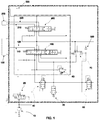
- FIG. 1 illustrates a schematic representation of the control system of the present invention, which is conceivable to lift a bucket of a loader of a work vehicle, such as a tractor.
- the loader may be offered as a built-in system in the machine, such as a construction equipment.
- the loader may be offered as an optional device which is assembled on a common tractor, such as an agricultural tractor.
- the loader uses the hydraulic transmission lines already available in a tractor.
- the invention is conceivable in a tractor in which a loader system is assembled in the tractor as an optional.
- work vehicles such as loaders, bulldozers, excavators, mini-loaders, pre-loaders, backhoe-loaders, etc.
- the loader which receives the system of the present invention is of the type that comprises a lifting mechanism 100, preferably one or two articulated arms, and a control bucket mechanism 200, preferably a pivot system that allows the bucket to turn around an axis. Both mechanisms are controlled, respectively, by a lifting valve 150 and a bucket valve 250.
- the work vehicles having a loader use oil as a fluid-control for controlling said bucket. Therefore and, preferably, the term "fluid” must be understood as specific hydraulic oil for this type of usage. Naturally, nothing prevents other fluids from being used in similar applications that use the system of the present invention, for instance, pressurized air for pneumatic uses.
- the lifting mechanisms 100 and bucket control 200 have, each one, a first and a second feeding passageways 110, 120, 210, 220 which work intermittently as fluid output and input for each valve, i.e., when a passageway is fed, the other one serves as a fluid output.
- each mechanism 100, 200 have two possible movements, considering that in the case of the lifting mechanism 100 there are, preferably, the lifting and lowering movements, and in the case of the bucket control 200 there are, preferably, clockwise and counter-clockwise rotations.
- each one of these valves 150, 250 has three switching positions A, B, C and six connections in each position, thus, comprising a 6/3 passageways valve.
- the six connections of each valve are divided into two central and four lateral connections.
- the lateral connections form a first and a second sideways 151, 152, 251, 252 in parallel disclosed in the switching position A and crossed in the switching disposition B.
- the central connections form a central passageway 153, 253 in the switching position C.
- valves 150, 250 promotes the direct fluid passage through them by the central passageway 153, 253 without controlling the respective mechanisms 100, 200.
- the first switching position A of valves 150, 250 promotes the fluid delivery to the first feeding passageway 110, 210 of the respective mechanisms 100, 200 through the first sideways 151, 251, and promotes, furthermore, this fluid return through the second feeding passageway 120, 220, through the second sideways 152, 252 comprising one of the two possible movements for each mechanism, as previously explained.
- the second switching position B of valves 150, 250 promotes the fluid delivery to the second feeding passageway 120, 220 of the respective mechanisms 100, 200 through the first sideways 151, 251, and promotes, furthermore, this fluid return through the first feeding passageway 110, 210, through the second sideways 152, 252, comprising a second possible movement for each mechanism.
- the switching of the lifting valve 150 and bucket valve 250 may provide the fluid passage through both valves 150, 250 without activating any of the mechanisms 100, 200, through the third switching position C; or might promote the control of the mechanisms in two possible movements through the first and the second switching positions A, B.
- valves 150, 250 may be performed through any adequate means, for instance, from a consumer's direct control, or from a vehicle control unit.
- Both lifting valve 150 and bucket valve 250 are connected one to another, and both are fed with fluid through a feeding source 10. All the fluid used in the system goes to a reservoir 500 connected to the feeding source, for its reuse.
- the lifting valve 150 is disclosed closer to the feeding source 10
- the bucket valve 250 is disclosed closer to the reservoir.
- source 10 is connected to a safety valve 60, which is connected to reservoir 500. Safety valve 60 opens when the pressure of the system reaches its maximum tolerated value, causing the fluid source 10 to be discharged directly into reservoir 500.
- the central passageway 153 of the closest valve to source 10, preferably the lifting valve 150, is fed directly through source 10.
- the central connections of valve 150 form a central passageway 153 for the direct passage of the fluid, as previously explained.
- the fluid thus, passes through the lifting valve 150 and goes towards the closest valve to reservoir 500, preferably the bucket valve 250, without activating any mechanism.
- the bucket valve 250 is also in the third switching position C, it works similarly to the first valve 150 through its central passageway 253, promoting the fluid's passage to reservoir 500 without activating any mechanism.
- the central passageway 153, 253 of valves 150, 250 is only used for the free and direct circulation of the fluid, without activating mechanisms.
- valves 150, 250 may still comprise a fourth switching position Y.
- This position interconnects the two feeding passageways 110, 120, 210, 220 of their respective valves directly to reservoir 500, in a way that it promotes the free movement of their respective mechanisms 100, 200.
- the lifting valve 150 In order to use this fourth switching position Y in valves 150, 250, the lifting valve 150 must have seven connections (thus comprising a fourth additional passageway 154) instead of six, in order to make it possible to promote the fluid passage towards reservoir 500 instead of directing it to the bucket valve 250, comprising thus the floating effect of the bucket 200 control mechanism.
- the sideways 151, 152, 251, 252 of the lifting valves 150 and the bucket valves 250 they are used to control mechanisms 100, 200.
- the first sideway 151 of the closest valve to source 10, preferably the lifting valve 150, is connected to a control valve 20 which is further connected to source 10.
- Control valve 20 has two switching positions D, E and three connections, i.e., it is a 3/2 passageways valve. Said valve 20 is switched through the increase or decrease of the pressure required by the system, or, in other words, the switching position of the control valve 20 is determined by the instantaneous pressure state of the system.
- control valve 20 is responsible for alternating the arrangements of the lifting valves 150 and the bucket valves 250 from being in series to being in parallel, according to the pressure state of the system.
- first switching position D corresponds to the arrangement in series
- second switching position E corresponds to the arrangement in parallel, as it will be further explained.
- the control valve 20 is configured in order to promote the connection of the lifting valves 150 and the bucket valves 250 in an arrangement in series or in parallel upon increase or decrease of the pressure required by the control system.
- the intensity of the pressure that switches the control valve 20 must be, preferably, a pressure closer to the maximum pressure tolerated by the system. Since, as previously explained, an arrangement in series requires a very high pressure in order to operate both mechanisms 100, 200 simultaneously, and this pressure may exceed the maximum level tolerated by the system, effectively reducing the possible maximum load of work of the vehicle. On the other hand, the arrangement in parallel spreads the pressure in different lines for each mechanism 100, 200, permitting them to operate with a maximum load simultaneously without a substantial pressure increase.
- control valve 20 switches from position D to position E while this pressure is exceeded, changing the arrangements of the valves 150, 250 from being in series to being in parallel, effectively requiring less pressure from the system for simultaneous operation of the mechanisms.
- control valve 20 switches from the position E to the position D when the system pressure is lower than the switching pressure of said valve 20.
- control valve 20 may occur through a return spring, which would be dimensioned to deform and promote the switching of the position of valve 20 from a certain pressure, in this case, the chosen switching pressure. Therefore, the return occurs through the spring when the pressure is reduced to below the switching pressure.
- any other switching means could be applied to the control valve 20, such as, for instance, through an electronic trigger (solenoids) supported by the pressure sensors.
- the first sideway 151 of the closest valve to the source 10, preferably the lifting valve 150, is connected to a control valve 20 which is further connected to the source 10.
- the control valve 20 is disclosed with its first switching position D as being its initial position, i.e., the system initial arrangement is the arrangement in series.
- the functioning of the arrangement in series of the present system is detailed as follows.
- this first switching position D the feeding pressure coming from the source 10 is directed towards the first passageway 151 of the lifting valve 150, which further activates the lifting mechanism 100 in case it has been switched to its first or second positions A, B.
- the fluid is directed towards the second passageway 152, which is connected to a direction valve 70.
- the direction valve 70 has two switching positions F, G and three connections, comprising a 3/2 passageways valve.
- the first switching position F allows the fluid flow coming from the second passageway 152 of the lifting valve 150 to be directed towards the first passageway 251 of the bucket valve 250, effectively comprising an arrangement in series of the lifting valves 150 and the bucket valves 250.
- the second switching position G directs the flow coming from the second passageway 152 of the lifting valve 150 towards reservoir 500.
- Said valve 70 is initially placed in its first switching position F, and it is controlled to its second switching position G when the control valve 20 is in its second switching position E, i.e., when the arrangement of the valves 150, 250 is in parallel.
- the direction valve 70 prevents the flow of the arrangement in series from influencing the functioning of the arrangement in parallel.
- the direction valve 70 connects the lifting valve 150 to the bucket valve 250 upon definition of an arrangement in series of valves 150,250, and connects the lifting valves 150 to the fluid reservoir 500 upon definition of a parallel connection of theses valves 150, 250.
- the return of valve 70 can be performed as the one of valve 20, through a return spring or an electromechanical system.
- the direction valve 70 when in its first switching position F, directs the fluid coming from the second passageway 152 of the lifting valve 150 to the first passageway 251 of the bucket valve 250.
- the bucket valve 250 activates the bucket control mechanism 200, and the fluid is directed through the second passageway 252 and to the reservoir 500.
- the first passageway A of the bucket valve 250 has a further direct connection with the third passageway C of the lifting valve, which allows the bucket valve 250 to activate the bucket control mechanism 200 individually in situations where the lifting valve 150 is not operating the lifting mechanism 100.
- control valve 20 is switched from its first position D to its second position E when the chosen switching pressure for said valve 20 is exceeded, thus, changing the arrangement of the valves 150, 250 from being in series to being in parallel.
- the control valve 20 In its switching position E, the control valve 20 directs the feeding flow coming from the source 10 to a pressure detection valve 30.
- the detection valve 30 has two switching positions H, I and two connections in each position, comprising a 2/2 passageways valve.
- the first switching position H is the initial position of valve 30, and in this position H referred valve prevents the passage of fluid coming from the control valve 20.
- the second switching position I of valve 30 allows the fluid passage from the control valve 20 towards the first passageway 151 of the lifting valve 150 and to the first passageway 251 of the bucket valve 250, effectively comprising an arrangement in parallel of both valves 150, 250.
- the return of the detection valve 30 can be done as the one of the control valves 20 and of the direction valve 70.
- the switching of the pressure detection valve 30 from the first position H to the second position I is performed when the second passageway of the lifting valve 150 is pressurized. This guarantees that the arrangement in parallel will only be defined when the lifting valve 150 and the bucket valve 250 are operating simultaneously in an arrangement in series.
- the pressure detection valve 30 is configured to allow the fluid passage coming from the control valve 20 towards the bucket valve 250 upon control of the lifting mechanism 100 through the lifting valve 150.
- an outflow control valve 40, 50 to each passageway 151, 251.
- the outflow control valve 40, 50 operates comparing the pressures that operate on it backwards and forwards and controlling, based on this information, the needed outflow for the functioning of the lifting and bucket valves 150, 250, thus preventing the pressure from one of these valves 150, 250 from influencing in each other's pressure.
- the system of the present invention alternates from the arrangement in series to the arrangement in parallel of valves 150, 250 when two conditions are achieved:
- the feeding flow of the source 10 is directed towards the first passageways 151, 251 of both lifting valves 150 and bucket valves 250, comprising, thus, an arrangement in parallel of both valves.
- the system of the present invention uses an arrangement in series of the lifting valves 150 and the bucket valves 250 when the active pressure in the system is not close to the maximum pressure tolerated, in a way that, in lightly loaded working situations, the feeding flow used is lower.
- the control valve 20 changes the arrangements of valves 150, 250 from being in series to being in parallel, resulting in the possibility of working with both mechanisms fully loaded.
- the benefits promoted by the system of the present invention include the elimination of the need to have an over-sized work vehicle for services with high loads, or even the need of having multiple vehicles with arrangements of distinct valves for distinct uses. Furthermore, the present system promotes the simultaneous use of the lifting and bucket control mechanisms without incurring in working velocity loss or reduction of the maximum load tolerated by the system.
Landscapes
- Engineering & Computer Science (AREA)
- Mining & Mineral Resources (AREA)
- Civil Engineering (AREA)
- General Engineering & Computer Science (AREA)
- Structural Engineering (AREA)
- Mechanical Engineering (AREA)
- Physics & Mathematics (AREA)
- Fluid Mechanics (AREA)
- Operation Control Of Excavators (AREA)
- Fluid-Pressure Circuits (AREA)
Abstract
Description
- The present invention relates to a control system applicable to a loader of a work vehicle, such as a tractor and, more specifically, the invention related to a hydraulic control system applicable to a loader of a work vehicle, in which valves arrangement and control logic enable the control of the elevation of the loader and of the bucket efficiently.
- In the technology field of work machines, the term "tractor" may be used to designate a large scale of vehicles, from those that effectively drive an implement or additional machine, until those that perform specific activities in an individual manner (generally, heavy work).
- Amongst this second type of tractor, are vehicles equipped with a loader , which perform, individually, the loading, the lifting and the disposal of several types of material. These vehicles having a loader are widely used for handling residues, construction material, and soil, amongst others.
- Considering this particular type of vehicle, its loader comprises a lifting mechanism (usually consisting of articulated arms or similar with hydraulic cylinders) and a mechanism to control the bucket (usually comprising a pivotable construction also with a hydraulic cylinder).
- Both the lifting and bucket control mechanisms are controlled through a logic of hydraulics, which uses a set of valves in order to direct the fluid towards each mechanism according to the operator's action.
- Usually, the control of said mechanisms is done from two distinct control systems. A first system uses an arrangement of valves in series in order to feed the mechanisms, in a way that the fluid pressure is concentrated in a single line. This system in series requires a small amount of fluid outflow to control both mechanisms, due to a certain velocity of operation, in a way that the work of a system with an arrangement of valves in series is performed rapidly.
- Nevertheless, the control system with an arrangement in series works with a substantially high pressure, since it demands the feeding of two mechanisms through a single line. Thus, the feeding pressure must be a sum of the required pressures for handling each mechanism, which drastically reduces the maximum load tolerated for a system of this type when both mechanisms work at the same time.
- It is understood, thus, that the control system with an arrangement in series has the disadvantage of loss of maximum load in situations where the lifting and bucket control mechanisms are simultaneously operated.
- Alternatively, a second type of control uses an arrangement of valves in parallel, in a way that both system mechanisms are controlled from parallel feeding lines. In this system configuration, the feeding pressure is distributed to the lines of each mechanism, drastically reducing the amount of pressure demanded by the system and enabling both mechanisms to operate with a maximum load simultaneously.
- However, a control system with a parallel arrangement requires a higher fluid flow in order to operate two lines simultaneously and, consequently, given a maximum feeding flow, the parallel system operates the lifting and the bucket control mechanisms in a lower speed if compared to a system in series. That being said, the use of a parallel system may result in a substantially lower productivity of the vehicle.
- It is important to note, furthermore, that the prior art does not raise teachings related to a control system of this type that uses both arrangements in series and in parallel, especially regarding work vehicles, such as tractors, which are equipped with a front loader as an optional and additional implement. It becomes evident, thus, that the consumer of this type of vehicle is forced to alternate between the use of a machine with a system in series and a machine with a system in parallel, depending on the use conditions. Alternatively, the consumer may choose a single system that has a load or flow capacity much higher than what is usually required, in a way that it overcomes the defects of the respective chosen system. Naturally, both options are economically unfeasible.
- In this sense, it is desirable that a control system for a loader of a work vehicle, such as a tractor, may guarantee its maximum load in the event of simultaneous control of the lifting and bucket control mechanisms, while it holds a minimum fluid flow during the operation of the vehicle in softer conditions, and thus promoting a high efficiency and adaptability of the system in a single vehicle.
- However, it is not disclosed in the prior art a control system for a loader that promotes the achievement of the benefits of both arrangements in series and in parallel depending on the working conditions of the vehicle.
- A first object of the present invention is to provide a control system for a loader of a work vehicle comprising an arrangement of valves that promote the use of both a in series and a in parallel feeding system, according to the working conditions of the system.
- A second object of the present invention is to provide a control system for a loader that promotes efficiency and adaptability to the work of the work vehicle, even in the event of simultaneous control of the lifting and bucket control mechanisms.
- A third object of the present invention is to provide a control system for a loader that promotes the simultaneous use of the lifting and bucket control mechanisms without causing loss working speed or reduction of the maximum load admissible to the system.
- The objects of the present invention are achieved from a control system for a loader of a work vehicle, the loader comprising a lifting mechanism and a bucket control mechanism, the lifting mechanism being controlled by a lifting valve, and the bucket control mechanism being controlled by a bucket valve.
- The control system comprises a control valve configured to promote the connection of the lifting and bucket valves in an arrangement in series or in parallel through the increase or decrease in the pressure required by the control system.
- Furthermore, the system comprises a pressure detection valve connected to the lifting valve, to the control valve and to the bucket valve, the pressure detection valve being configured to promote the connection between the control valve to the bucket valve upon control of the lifting mechanism by the lifting valve.
- The objects of the present invention are achieved from a control system for a loader of a work vehicle, the loader comprising a lifting mechanism and a bucket control mechanism, being the lifting mechanism controlled by a lifting valve, and the bucket control mechanism being controlled by a bucket valve. The lifting and bucket valves are connected one to one another, and the system comprises a control valve configured to define a connection in series or a parallel connection of the lifting and bucket valves upon increase or decrease of the pressure required by the control system.
- In addition, the system comprises a pressure detection valve connected to the lifting valve, to the control valve and to the bucket valve, being the pressure detection valve configured to promote the fluid passage from the control valve to the bucket valve upon control of the lifting mechanism by the lifting valve.
- The system also comprises a direction valve connected to the lifting valve, to the bucket valve, and to a fluid reservoir, the direction valve connecting the lifting valve to the bucket valve upon definition of a connection in series, and connecting the lifting valve to the fluid reservoir upon definition of a parallel connection.
- Furthermore, the lifting valve and the bucket valve are provided, each one, with a first, a second and a third switching positions, the bucket valve further having a first, a second and a third passageways. The control valve is provided with a first and a second switching positions.
- In this sense, in its first switching position, the control valve connects itself to the lifting valve and comprises an arrangement in series between the lifting valve and the bucket valve. In its second switching position, the control valve connects itself to the lifting valve and to the bucket valve, comprising an arrangement in parallel between both valves.
- The present invention will be, subsequently, further illustrated based on an execution example provided in the drawings. In the Figures:
-
FIG. 1 - is a schematic representation of a preferred embodiment of the control system of the present invention; -
FIG. 2 - is a detail of the lifting valve used in the preferred embodiment of the system of the present invention; -
FIG. 3 - is a detail of the bucket valve used in the preferred embodiment of the system of the present invention; -
FIG. 4 - is a detail of the control valve used in the preferred embodiment of the system of the present invention; -
FIG. 5 - is a detail of the pressure detection valve used in the preferred embodiment of the system of the present invention; and -
FIG. 6 - is a detail of the direction valve used in the preferred embodiment of the system of the present invention. - The control system of the present invention comprises a combination of arrangements of valves in series and in parallel which operations overlap depending on the working conditions of the system. The control of the arrangements in series and in parallel is performed by a logic of valves through the monitoring of the pressure condition within the system, promoting, thus, an automatic alternation of the active arrangement in the system, according to its needs, as it will be further illustrated.
-
FIG. 1 illustrates a schematic representation of the control system of the present invention, which is conceivable to lift a bucket of a loader of a work vehicle, such as a tractor. Overall, the loader may be offered as a built-in system in the machine, such as a construction equipment. Alternatively, the loader may be offered as an optional device which is assembled on a common tractor, such as an agricultural tractor. In this last case, the loader uses the hydraulic transmission lines already available in a tractor. Preferably, the invention is conceivable in a tractor in which a loader system is assembled in the tractor as an optional. However, nothing prevents it to be also conceived to other work vehicles, such as loaders, bulldozers, excavators, mini-loaders, pre-loaders, backhoe-loaders, etc. - The loader which receives the system of the present invention is of the type that comprises a
lifting mechanism 100, preferably one or two articulated arms, and acontrol bucket mechanism 200, preferably a pivot system that allows the bucket to turn around an axis. Both mechanisms are controlled, respectively, by alifting valve 150 and abucket valve 250. - Usually, the work vehicles having a loader use oil as a fluid-control for controlling said bucket. Therefore and, preferably, the term "fluid" must be understood as specific hydraulic oil for this type of usage. Naturally, nothing prevents other fluids from being used in similar applications that use the system of the present invention, for instance, pressurized air for pneumatic uses.
- The
lifting mechanisms 100 andbucket control 200 have, each one, a first and asecond feeding passageways mechanism lifting mechanism 100 there are, preferably, the lifting and lowering movements, and in the case of thebucket control 200 there are, preferably, clockwise and counter-clockwise rotations. - In this sense, both the
lifting valves 150 and thebucket valves 250 control their respective mechanisms' movements. As disclosed inFIG. 2 and FIG. 3 , each one of thesevalves - The lateral connections form a first and a second sideways 151, 152, 251, 252 in parallel disclosed in the switching position A and crossed in the switching disposition B. The central connections form a
central passageway - The third switching position C of
valves central passageway respective mechanisms - The first switching position A of
valves first feeding passageway respective mechanisms second feeding passageway - The second switching position B of
valves second feeding passageway respective mechanisms first feeding passageway - Thus, the switching of the lifting
valve 150 andbucket valve 250 may provide the fluid passage through bothvalves mechanisms - The switching of
valves - Both lifting
valve 150 andbucket valve 250 are connected one to another, and both are fed with fluid through a feedingsource 10. All the fluid used in the system goes to areservoir 500 connected to the feeding source, for its reuse. In this preferred embodiment, the liftingvalve 150 is disclosed closer to thefeeding source 10, and thebucket valve 250 is disclosed closer to the reservoir. However, it is important to note that the inversion of thevalves source 10 and to thereservoir 500 does not change the system functions. Furthermore,source 10 is connected to asafety valve 60, which is connected toreservoir 500.Safety valve 60 opens when the pressure of the system reaches its maximum tolerated value, causing thefluid source 10 to be discharged directly intoreservoir 500. - The
central passageway 153 of the closest valve tosource 10, preferably the liftingvalve 150, is fed directly throughsource 10. During the third switching position C, the central connections ofvalve 150 form acentral passageway 153 for the direct passage of the fluid, as previously explained. The fluid, thus, passes through the liftingvalve 150 and goes towards the closest valve toreservoir 500, preferably thebucket valve 250, without activating any mechanism. In case thebucket valve 250 is also in the third switching position C, it works similarly to thefirst valve 150 through itscentral passageway 253, promoting the fluid's passage toreservoir 500 without activating any mechanism. In this sense, thecentral passageway valves - Alternatively,
valves passageways reservoir 500, in a way that it promotes the free movement of theirrespective mechanisms valves valve 150 must have seven connections (thus comprising a fourth additional passageway 154) instead of six, in order to make it possible to promote the fluid passage towardsreservoir 500 instead of directing it to thebucket valve 250, comprising thus the floating effect of thebucket 200 control mechanism. - As regards to the sideways 151, 152, 251, 252 of the lifting
valves 150 and thebucket valves 250 they are used to controlmechanisms first sideway 151 of the closest valve tosource 10, preferably the liftingvalve 150, is connected to acontrol valve 20 which is further connected tosource 10. -
Control valve 20 has two switching positions D, E and three connections, i.e., it is a 3/2 passageways valve. Saidvalve 20 is switched through the increase or decrease of the pressure required by the system, or, in other words, the switching position of thecontrol valve 20 is determined by the instantaneous pressure state of the system. - That being said, the
control valve 20 is responsible for alternating the arrangements of the liftingvalves 150 and thebucket valves 250 from being in series to being in parallel, according to the pressure state of the system. As it can be noted inFIG. 4 the first switching position D corresponds to the arrangement in series, while the second switching position E corresponds to the arrangement in parallel, as it will be further explained. In other words, thecontrol valve 20 is configured in order to promote the connection of the liftingvalves 150 and thebucket valves 250 in an arrangement in series or in parallel upon increase or decrease of the pressure required by the control system. - The intensity of the pressure that switches the
control valve 20 must be, preferably, a pressure closer to the maximum pressure tolerated by the system. Since, as previously explained, an arrangement in series requires a very high pressure in order to operate bothmechanisms mechanism
simultaneously without a substantial pressure increase. - Thus, once its switching pressure is determined, the
control valve 20 switches from position D to position E while this pressure is exceeded, changing the arrangements of thevalves - On the other hand, the arrangement in parallel requires a higher fluid flow in order to operate a same maximum load in comparison to the system in series, which is not desirable in a situation where only one
mechanism control valve 20 switches from the position E to the position D when the system pressure is lower than the switching pressure of saidvalve 20. - The switching of
control valve 20 may occur through a return spring, which would be dimensioned to deform and promote the switching of the position ofvalve 20 from a certain pressure, in this case, the chosen switching pressure. Therefore, the return occurs through the spring when the pressure is reduced to below the switching pressure. However, any other switching means could be applied to thecontrol valve 20, such as, for instance, through an electronic trigger (solenoids) supported by the pressure sensors. - As previously explained, the
first sideway 151 of the closest valve to thesource 10, preferably the liftingvalve 150, is connected to acontrol valve 20 which is further connected to thesource 10. Thecontrol valve 20 is disclosed with its first switching position D as being its initial position, i.e., the system initial arrangement is the arrangement in series. Thus, the functioning of the arrangement in series of the present system is detailed as follows. - In this first switching position D, the feeding pressure coming from the
source 10 is directed towards thefirst passageway 151 of the liftingvalve 150, which further activates thelifting mechanism 100 in case it has been switched to its first or second positions A, B. - In case the
lifting mechanism 100 is activated, the fluid is directed towards thesecond passageway 152, which is connected to adirection valve 70. As it can be noted inFIG. 6 , thedirection valve 70 has two switching positions F, G and three connections, comprising a 3/2 passageways valve. The first switching position F allows the fluid flow coming from thesecond passageway 152 of the liftingvalve 150 to be directed towards thefirst passageway 251 of thebucket valve 250, effectively comprising an arrangement in series of the liftingvalves 150 and thebucket valves 250. The second switching position G directs the flow coming from thesecond passageway 152 of the liftingvalve 150 towardsreservoir 500. - Said
valve 70 is initially placed in its first switching position F, and it is controlled to its second switching position G when thecontrol valve 20 is in its second switching position E, i.e., when the arrangement of thevalves direction valve 70 prevents the flow of the arrangement in series from influencing the functioning of the arrangement in parallel. In other words, thedirection valve 70 connects the liftingvalve 150 to thebucket valve 250 upon definition of an arrangement in series of valves 150,250, and connects the liftingvalves 150 to thefluid reservoir 500 upon definition of a parallel connection oftheses valves valve 70 can be performed as the one ofvalve 20, through a return spring or an electromechanical system. - As previously mentioned, the
direction valve 70, when in its first switching position F, directs the fluid coming from thesecond passageway 152 of the liftingvalve 150 to thefirst passageway 251 of thebucket valve 250. In case it is switched to the first or second positions A, B, thebucket valve 250 activates thebucket control mechanism 200, and the fluid is directed through thesecond passageway 252 and to thereservoir 500. - The first passageway A of the
bucket valve 250 has a further direct connection with the third passageway C of the lifting valve, which allows thebucket valve 250 to activate thebucket control mechanism 200 individually in situations where the liftingvalve 150 is not operating thelifting mechanism 100. - As previously explained, the
control valve 20 is switched from its first position D to its second position E when the chosen switching pressure for saidvalve 20 is exceeded, thus, changing the arrangement of thevalves control valve 20 directs the feeding flow coming from thesource 10 to apressure detection valve 30. - As it can be noted in
FIG. 5 , thedetection valve 30 has two switching positions H, I and two connections in each position, comprising a 2/2 passageways valve. The first switching position H is the initial position ofvalve 30, and in this position H referred valve prevents the passage of fluid coming from thecontrol valve 20. The second switching position I ofvalve 30 allows the fluid passage from thecontrol valve 20 towards thefirst passageway 151 of the liftingvalve 150 and to thefirst passageway 251 of thebucket valve 250, effectively comprising an arrangement in parallel of bothvalves detection valve 30 can be done as the one of thecontrol valves 20 and of thedirection valve 70. - The switching of the
pressure detection valve 30 from the first position H to the second position I is performed when the second passageway of the liftingvalve 150 is pressurized. This guarantees that the arrangement in parallel will only be defined when the liftingvalve 150 and thebucket valve 250 are operating simultaneously in an arrangement in series. Thus, thepressure detection valve 30 is configured to allow the fluid passage coming from thecontrol valve 20 towards thebucket valve 250 upon control of thelifting mechanism 100 through the liftingvalve 150. - Furthermore, between the
pressure detection valve 30 and the first passageways of the lifting andbucket valves outflow control valve passageway outflow control valve bucket valves valves - Therefore, the system of the present invention alternates from the arrangement in series to the arrangement in parallel of
valves - 1st: The
control valve 20 must be switched to its second position E (which occurs when the chosen pressure for switching of thecontrol valve 20 is exceeded); and - 2nd: The
pressure detection valve 30 must be switched to its second position I (which occurs when the liftingvalve 150 is working simultaneously and in series with the bucket valve 250). - Upon achievement of both conditions, the feeding flow of the
source 10 is directed towards thefirst passageways valves 150 andbucket valves 250, comprising, thus, an arrangement in parallel of both valves. - In view of the above, it becomes clear that the system of the present invention promotes both the use of a valves arrangement in series as a parallel feeding system, according to the working conditions of the system, in a way that the benefits of both arrangements are reached in the most convenient situations.
- Thus, the system of the present invention uses an arrangement in series of the lifting
valves 150 and thebucket valves 250 when the active pressure in the system is not close to the maximum pressure tolerated, in a way that, in lightly loaded working situations, the feeding flow used is lower. On the other hand, when the active pressure in the system is close to the maximum pressure tolerated and bothmechanisms control valve 20 changes the arrangements ofvalves - The benefits promoted by the system of the present invention include the elimination of the need to have an over-sized work vehicle for services with high loads, or even the need of having multiple vehicles with arrangements of distinct valves for distinct uses. Furthermore, the present system promotes the simultaneous use of the lifting and bucket control mechanisms without incurring in working velocity loss or reduction of the maximum load tolerated by the system.
- Since a preferred embodiment example has been disclosed, it must be understood that the scope of the present invention covers other possible variations, being limited only by the content of the appended claims, therein included the possible equivalents.
Claims (7)
- Control system for a loader of a work vehicle, in which the loader comprises:a lifting mechanism (100) and a bucket control mechanism (200), the lifting mechanism (100) being controlled by a lifting valve (150), the bucket control mechanism (200) being controlled by a bucket valve (250), the control system characterized in thatit comprises a control valve (20) configured to promote the connection of the lifting valves (150) and the bucket valves (250) in an arrangement in series or in parallel upon increase or decrease of the pressure required by the control system.
- Control system of claim 1, characterized in that it comprises a pressure detection valve (30) connected to the lifting valve (150), to the control valve (20) and to the bucket valve (250), being the pressure detection valve (30) configured to promote the connection between the control valve (20) to the bucket valve (250) upon control of the lifting mechanism (100) by the lifting valve (150).
- Control system of claim 1, characterized in that it comprises a direction valve (70) connected to the lifting valve (150), to the bucket valve (250) and to a fluid reservoir (500), to the direction valve (70) connecting the lifting valve (150) to the bucket valve (250) upon definition of a connection in series, and connecting the lifting valve (150) to the fluid reservoir (500) upon definition of a parallel connection.
- Control system of claim 1, characterized in that the lifting valve (150) and the bucket valve (250) have, each one, a first a second and a third switching positions (A, B, C), the bucket valve (250) having a first, a second and a third passageways (151, 152, 153).
- Control system of claim 1, characterized in that the control valve (20) has a first and a second switching positions (D, E).
- Control system of claims 4 and 5, characterized in that, in its first switching position (D), the control valve (20) is connected to the lifting valve (150) and comprises an arrangement in series between the lifting valve (150) and the bucket valve (250).
- Control system of claims 4 and 5, characterized in that, in its second switching position (E), the control valve (20) connects to the lifting valve (150) and to the bucket valve (250), comprising an arrangement in parallel between both valves (150, 250).
Applications Claiming Priority (1)
| Application Number | Priority Date | Filing Date | Title |
|---|---|---|---|
| BR102016025741-7A BR102016025741B1 (en) | 2016-11-03 | 2016-11-03 | Control system for a wheel loader of a work vehicle |
Publications (2)
| Publication Number | Publication Date |
|---|---|
| EP3318679A1 true EP3318679A1 (en) | 2018-05-09 |
| EP3318679B1 EP3318679B1 (en) | 2019-08-28 |
Family
ID=60201441
Family Applications (1)
| Application Number | Title | Priority Date | Filing Date |
|---|---|---|---|
| EP17199390.0A Active EP3318679B1 (en) | 2016-11-03 | 2017-10-31 | Control system for a loader of a work vehicle |
Country Status (2)
| Country | Link |
|---|---|
| EP (1) | EP3318679B1 (en) |
| BR (1) | BR102016025741B1 (en) |
Cited By (1)
| Publication number | Priority date | Publication date | Assignee | Title |
|---|---|---|---|---|
| CN111219376A (en) * | 2020-03-20 | 2020-06-02 | 第一拖拉机股份有限公司 | Multi-way valve integrating electric control lifting and mechanical hydraulic output |
Citations (3)
| Publication number | Priority date | Publication date | Assignee | Title |
|---|---|---|---|---|
| JPS63115903A (en) * | 1986-11-05 | 1988-05-20 | Kobe Steel Ltd | Oil pressure control device |
| DE10109510A1 (en) * | 2000-07-14 | 2002-01-31 | Komatsu Mfg Co Ltd | Device for actuator control of hydraulic drive machines |
| WO2009075613A1 (en) * | 2007-12-12 | 2009-06-18 | Volvo Construction Equipment Ab | A method for when necessary automatically limiting a pressure in a hydrualic system during operation |
-
2016
- 2016-11-03 BR BR102016025741-7A patent/BR102016025741B1/en active IP Right Grant
-
2017
- 2017-10-31 EP EP17199390.0A patent/EP3318679B1/en active Active
Patent Citations (3)
| Publication number | Priority date | Publication date | Assignee | Title |
|---|---|---|---|---|
| JPS63115903A (en) * | 1986-11-05 | 1988-05-20 | Kobe Steel Ltd | Oil pressure control device |
| DE10109510A1 (en) * | 2000-07-14 | 2002-01-31 | Komatsu Mfg Co Ltd | Device for actuator control of hydraulic drive machines |
| WO2009075613A1 (en) * | 2007-12-12 | 2009-06-18 | Volvo Construction Equipment Ab | A method for when necessary automatically limiting a pressure in a hydrualic system during operation |
Cited By (1)
| Publication number | Priority date | Publication date | Assignee | Title |
|---|---|---|---|---|
| CN111219376A (en) * | 2020-03-20 | 2020-06-02 | 第一拖拉机股份有限公司 | Multi-way valve integrating electric control lifting and mechanical hydraulic output |
Also Published As
| Publication number | Publication date |
|---|---|
| BR102016025741B1 (en) | 2022-03-29 |
| BR102016025741A2 (en) | 2018-05-29 |
| EP3318679B1 (en) | 2019-08-28 |
Similar Documents
| Publication | Publication Date | Title |
|---|---|---|
| EP1477686B1 (en) | Hydraulic controller for working machine | |
| US9091281B2 (en) | System for allocating fluid from multiple pumps to a plurality of hydraulic functions on a priority basis | |
| US6854268B2 (en) | Hydraulic control system with energy recovery | |
| US6837045B2 (en) | Electrohydraulic lifting control device for industrial trucks | |
| US20100083651A1 (en) | Circuit for controlling a double-action hydraulic drive cylinder | |
| US20030150210A1 (en) | Fluid pressure circuit | |
| JP2005098455A (en) | Hydraulic controller of industrial machinery | |
| US8875506B2 (en) | Work vehicle lifting performance | |
| CN106321537B (en) | Hydraulic control system and corresponding mobile working device | |
| CN106151147B (en) | Hydraulic system, control method thereof and machine comprising hydraulic system | |
| WO2009075613A1 (en) | A method for when necessary automatically limiting a pressure in a hydrualic system during operation | |
| US3800670A (en) | High pressure implement hydraulic circuit | |
| EP3318679B1 (en) | Control system for a loader of a work vehicle | |
| CN211448991U (en) | controlling device | |
| EP2672022B1 (en) | Hydarulic fluid control system for a work vehicle | |
| US20250052035A1 (en) | Hydraulic Control System in Working Machine | |
| US6761027B2 (en) | Pressure-compensated hydraulic circuit with regeneration | |
| US20250067023A1 (en) | Hydraulic control system in working machine | |
| EP2910796B1 (en) | Assembly with a control valve device with a float position | |
| KR102411520B1 (en) | Low noise control algorithm for hydraulic systems | |
| US6205781B1 (en) | Fluid control system including a work element and a valve arrangement for selectively supplying pressurized fluid thereto from two pressurized fluid sources | |
| JP6726127B2 (en) | Hydraulic system | |
| KR20140010042A (en) | Load sense control with standby mode in case of overload | |
| US8763388B2 (en) | Hydraulic system having a backpressure control valve | |
| JP5435979B2 (en) | Hydrostatic drive system |
Legal Events
| Date | Code | Title | Description |
|---|---|---|---|
| PUAI | Public reference made under article 153(3) epc to a published international application that has entered the european phase |
Free format text: ORIGINAL CODE: 0009012 |
|
| STAA | Information on the status of an ep patent application or granted ep patent |
Free format text: STATUS: THE APPLICATION HAS BEEN PUBLISHED |
|
| AK | Designated contracting states |
Kind code of ref document: A1 Designated state(s): AL AT BE BG CH CY CZ DE DK EE ES FI FR GB GR HR HU IE IS IT LI LT LU LV MC MK MT NL NO PL PT RO RS SE SI SK SM TR |
|
| AX | Request for extension of the european patent |
Extension state: BA ME |
|
| STAA | Information on the status of an ep patent application or granted ep patent |
Free format text: STATUS: REQUEST FOR EXAMINATION WAS MADE |
|
| 17P | Request for examination filed |
Effective date: 20181109 |
|
| RBV | Designated contracting states (corrected) |
Designated state(s): AL AT BE BG CH CY CZ DE DK EE ES FI FR GB GR HR HU IE IS IT LI LT LU LV MC MK MT NL NO PL PT RO RS SE SI SK SM TR |
|
| RIC1 | Information provided on ipc code assigned before grant |
Ipc: E02F 3/42 20060101AFI20190208BHEP Ipc: E02F 9/22 20060101ALI20190208BHEP |
|
| GRAP | Despatch of communication of intention to grant a patent |
Free format text: ORIGINAL CODE: EPIDOSNIGR1 |
|
| STAA | Information on the status of an ep patent application or granted ep patent |
Free format text: STATUS: GRANT OF PATENT IS INTENDED |
|
| INTG | Intention to grant announced |
Effective date: 20190326 |
|
| GRAS | Grant fee paid |
Free format text: ORIGINAL CODE: EPIDOSNIGR3 |
|
| GRAA | (expected) grant |
Free format text: ORIGINAL CODE: 0009210 |
|
| STAA | Information on the status of an ep patent application or granted ep patent |
Free format text: STATUS: THE PATENT HAS BEEN GRANTED |
|
| AK | Designated contracting states |
Kind code of ref document: B1 Designated state(s): AL AT BE BG CH CY CZ DE DK EE ES FI FR GB GR HR HU IE IS IT LI LT LU LV MC MK MT NL NO PL PT RO RS SE SI SK SM TR |
|
| REG | Reference to a national code |
Ref country code: GB Ref legal event code: FG4D |
|
| REG | Reference to a national code |
Ref country code: CH Ref legal event code: EP |
|
| REG | Reference to a national code |
Ref country code: DE Ref legal event code: R096 Ref document number: 602017006531 Country of ref document: DE |
|
| REG | Reference to a national code |
Ref country code: AT Ref legal event code: REF Ref document number: 1172576 Country of ref document: AT Kind code of ref document: T Effective date: 20190915 |
|
| REG | Reference to a national code |
Ref country code: IE Ref legal event code: FG4D |
|
| REG | Reference to a national code |
Ref country code: NL Ref legal event code: MP Effective date: 20190828 |
|
| REG | Reference to a national code |
Ref country code: LT Ref legal event code: MG4D |
|
| PG25 | Lapsed in a contracting state [announced via postgrant information from national office to epo] |
Ref country code: NO Free format text: LAPSE BECAUSE OF FAILURE TO SUBMIT A TRANSLATION OF THE DESCRIPTION OR TO PAY THE FEE WITHIN THE PRESCRIBED TIME-LIMIT Effective date: 20191128 Ref country code: HR Free format text: LAPSE BECAUSE OF FAILURE TO SUBMIT A TRANSLATION OF THE DESCRIPTION OR TO PAY THE FEE WITHIN THE PRESCRIBED TIME-LIMIT Effective date: 20190828 Ref country code: NL Free format text: LAPSE BECAUSE OF FAILURE TO SUBMIT A TRANSLATION OF THE DESCRIPTION OR TO PAY THE FEE WITHIN THE PRESCRIBED TIME-LIMIT Effective date: 20190828 Ref country code: PT Free format text: LAPSE BECAUSE OF FAILURE TO SUBMIT A TRANSLATION OF THE DESCRIPTION OR TO PAY THE FEE WITHIN THE PRESCRIBED TIME-LIMIT Effective date: 20191230 Ref country code: BG Free format text: LAPSE BECAUSE OF FAILURE TO SUBMIT A TRANSLATION OF THE DESCRIPTION OR TO PAY THE FEE WITHIN THE PRESCRIBED TIME-LIMIT Effective date: 20191128 Ref country code: LT Free format text: LAPSE BECAUSE OF FAILURE TO SUBMIT A TRANSLATION OF THE DESCRIPTION OR TO PAY THE FEE WITHIN THE PRESCRIBED TIME-LIMIT Effective date: 20190828 Ref country code: FI Free format text: LAPSE BECAUSE OF FAILURE TO SUBMIT A TRANSLATION OF THE DESCRIPTION OR TO PAY THE FEE WITHIN THE PRESCRIBED TIME-LIMIT Effective date: 20190828 Ref country code: SE Free format text: LAPSE BECAUSE OF FAILURE TO SUBMIT A TRANSLATION OF THE DESCRIPTION OR TO PAY THE FEE WITHIN THE PRESCRIBED TIME-LIMIT Effective date: 20190828 |
|
| PG25 | Lapsed in a contracting state [announced via postgrant information from national office to epo] |
Ref country code: AL Free format text: LAPSE BECAUSE OF FAILURE TO SUBMIT A TRANSLATION OF THE DESCRIPTION OR TO PAY THE FEE WITHIN THE PRESCRIBED TIME-LIMIT Effective date: 20190828 Ref country code: GR Free format text: LAPSE BECAUSE OF FAILURE TO SUBMIT A TRANSLATION OF THE DESCRIPTION OR TO PAY THE FEE WITHIN THE PRESCRIBED TIME-LIMIT Effective date: 20191129 Ref country code: RS Free format text: LAPSE BECAUSE OF FAILURE TO SUBMIT A TRANSLATION OF THE DESCRIPTION OR TO PAY THE FEE WITHIN THE PRESCRIBED TIME-LIMIT Effective date: 20190828 Ref country code: IS Free format text: LAPSE BECAUSE OF FAILURE TO SUBMIT A TRANSLATION OF THE DESCRIPTION OR TO PAY THE FEE WITHIN THE PRESCRIBED TIME-LIMIT Effective date: 20191228 Ref country code: LV Free format text: LAPSE BECAUSE OF FAILURE TO SUBMIT A TRANSLATION OF THE DESCRIPTION OR TO PAY THE FEE WITHIN THE PRESCRIBED TIME-LIMIT Effective date: 20190828 Ref country code: ES Free format text: LAPSE BECAUSE OF FAILURE TO SUBMIT A TRANSLATION OF THE DESCRIPTION OR TO PAY THE FEE WITHIN THE PRESCRIBED TIME-LIMIT Effective date: 20190828 |
|
| REG | Reference to a national code |
Ref country code: AT Ref legal event code: MK05 Ref document number: 1172576 Country of ref document: AT Kind code of ref document: T Effective date: 20190828 |
|
| PG25 | Lapsed in a contracting state [announced via postgrant information from national office to epo] |
Ref country code: TR Free format text: LAPSE BECAUSE OF FAILURE TO SUBMIT A TRANSLATION OF THE DESCRIPTION OR TO PAY THE FEE WITHIN THE PRESCRIBED TIME-LIMIT Effective date: 20190828 |
|
| PG25 | Lapsed in a contracting state [announced via postgrant information from national office to epo] |
Ref country code: RO Free format text: LAPSE BECAUSE OF FAILURE TO SUBMIT A TRANSLATION OF THE DESCRIPTION OR TO PAY THE FEE WITHIN THE PRESCRIBED TIME-LIMIT Effective date: 20190828 Ref country code: DK Free format text: LAPSE BECAUSE OF FAILURE TO SUBMIT A TRANSLATION OF THE DESCRIPTION OR TO PAY THE FEE WITHIN THE PRESCRIBED TIME-LIMIT Effective date: 20190828 Ref country code: AT Free format text: LAPSE BECAUSE OF FAILURE TO SUBMIT A TRANSLATION OF THE DESCRIPTION OR TO PAY THE FEE WITHIN THE PRESCRIBED TIME-LIMIT Effective date: 20190828 Ref country code: EE Free format text: LAPSE BECAUSE OF FAILURE TO SUBMIT A TRANSLATION OF THE DESCRIPTION OR TO PAY THE FEE WITHIN THE PRESCRIBED TIME-LIMIT Effective date: 20190828 Ref country code: PL Free format text: LAPSE BECAUSE OF FAILURE TO SUBMIT A TRANSLATION OF THE DESCRIPTION OR TO PAY THE FEE WITHIN THE PRESCRIBED TIME-LIMIT Effective date: 20190828 |
|
| PG25 | Lapsed in a contracting state [announced via postgrant information from national office to epo] |
Ref country code: CZ Free format text: LAPSE BECAUSE OF FAILURE TO SUBMIT A TRANSLATION OF THE DESCRIPTION OR TO PAY THE FEE WITHIN THE PRESCRIBED TIME-LIMIT Effective date: 20190828 Ref country code: SK Free format text: LAPSE BECAUSE OF FAILURE TO SUBMIT A TRANSLATION OF THE DESCRIPTION OR TO PAY THE FEE WITHIN THE PRESCRIBED TIME-LIMIT Effective date: 20190828 Ref country code: MC Free format text: LAPSE BECAUSE OF FAILURE TO SUBMIT A TRANSLATION OF THE DESCRIPTION OR TO PAY THE FEE WITHIN THE PRESCRIBED TIME-LIMIT Effective date: 20190828 Ref country code: IS Free format text: LAPSE BECAUSE OF FAILURE TO SUBMIT A TRANSLATION OF THE DESCRIPTION OR TO PAY THE FEE WITHIN THE PRESCRIBED TIME-LIMIT Effective date: 20200224 Ref country code: SM Free format text: LAPSE BECAUSE OF FAILURE TO SUBMIT A TRANSLATION OF THE DESCRIPTION OR TO PAY THE FEE WITHIN THE PRESCRIBED TIME-LIMIT Effective date: 20190828 |
|
| REG | Reference to a national code |
Ref country code: DE Ref legal event code: R097 Ref document number: 602017006531 Country of ref document: DE |
|
| PLBE | No opposition filed within time limit |
Free format text: ORIGINAL CODE: 0009261 |
|
| STAA | Information on the status of an ep patent application or granted ep patent |
Free format text: STATUS: NO OPPOSITION FILED WITHIN TIME LIMIT |
|
| PG2D | Information on lapse in contracting state deleted |
Ref country code: IS |
|
| PG25 | Lapsed in a contracting state [announced via postgrant information from national office to epo] |
Ref country code: LU Free format text: LAPSE BECAUSE OF NON-PAYMENT OF DUE FEES Effective date: 20191031 |
|
| 26N | No opposition filed |
Effective date: 20200603 |
|
| REG | Reference to a national code |
Ref country code: BE Ref legal event code: MM Effective date: 20191031 |
|
| PG25 | Lapsed in a contracting state [announced via postgrant information from national office to epo] |
Ref country code: SI Free format text: LAPSE BECAUSE OF FAILURE TO SUBMIT A TRANSLATION OF THE DESCRIPTION OR TO PAY THE FEE WITHIN THE PRESCRIBED TIME-LIMIT Effective date: 20190828 Ref country code: BE Free format text: LAPSE BECAUSE OF NON-PAYMENT OF DUE FEES Effective date: 20191031 |
|
| PG25 | Lapsed in a contracting state [announced via postgrant information from national office to epo] |
Ref country code: IE Free format text: LAPSE BECAUSE OF NON-PAYMENT OF DUE FEES Effective date: 20191031 |
|
| PG25 | Lapsed in a contracting state [announced via postgrant information from national office to epo] |
Ref country code: CY Free format text: LAPSE BECAUSE OF FAILURE TO SUBMIT A TRANSLATION OF THE DESCRIPTION OR TO PAY THE FEE WITHIN THE PRESCRIBED TIME-LIMIT Effective date: 20190828 |
|
| REG | Reference to a national code |
Ref country code: CH Ref legal event code: PL |
|
| PG25 | Lapsed in a contracting state [announced via postgrant information from national office to epo] |
Ref country code: CH Free format text: LAPSE BECAUSE OF FAILURE TO SUBMIT A TRANSLATION OF THE DESCRIPTION OR TO PAY THE FEE WITHIN THE PRESCRIBED TIME-LIMIT Effective date: 20201031 Ref country code: LI Free format text: LAPSE BECAUSE OF FAILURE TO SUBMIT A TRANSLATION OF THE DESCRIPTION OR TO PAY THE FEE WITHIN THE PRESCRIBED TIME-LIMIT Effective date: 20201031 |
|
| PG25 | Lapsed in a contracting state [announced via postgrant information from national office to epo] |
Ref country code: MT Free format text: LAPSE BECAUSE OF FAILURE TO SUBMIT A TRANSLATION OF THE DESCRIPTION OR TO PAY THE FEE WITHIN THE PRESCRIBED TIME-LIMIT Effective date: 20190828 Ref country code: HU Free format text: LAPSE BECAUSE OF FAILURE TO SUBMIT A TRANSLATION OF THE DESCRIPTION OR TO PAY THE FEE WITHIN THE PRESCRIBED TIME-LIMIT; INVALID AB INITIO Effective date: 20171031 |
|
| GBPC | Gb: european patent ceased through non-payment of renewal fee |
Effective date: 20211031 |
|
| PG25 | Lapsed in a contracting state [announced via postgrant information from national office to epo] |
Ref country code: MK Free format text: LAPSE BECAUSE OF FAILURE TO SUBMIT A TRANSLATION OF THE DESCRIPTION OR TO PAY THE FEE WITHIN THE PRESCRIBED TIME-LIMIT Effective date: 20190828 |
|
| PG25 | Lapsed in a contracting state [announced via postgrant information from national office to epo] |
Ref country code: GB Free format text: LAPSE BECAUSE OF NON-PAYMENT OF DUE FEES Effective date: 20211031 |
|
| PGFP | Annual fee paid to national office [announced via postgrant information from national office to epo] |
Ref country code: DE Payment date: 20251028 Year of fee payment: 9 |
|
| PGFP | Annual fee paid to national office [announced via postgrant information from national office to epo] |
Ref country code: IT Payment date: 20251024 Year of fee payment: 9 |
|
| PGFP | Annual fee paid to national office [announced via postgrant information from national office to epo] |
Ref country code: FR Payment date: 20251027 Year of fee payment: 9 |