EP3318667A1 - Nonwoven fabric and production method for same - Google Patents
Nonwoven fabric and production method for same Download PDFInfo
- Publication number
- EP3318667A1 EP3318667A1 EP16818032.1A EP16818032A EP3318667A1 EP 3318667 A1 EP3318667 A1 EP 3318667A1 EP 16818032 A EP16818032 A EP 16818032A EP 3318667 A1 EP3318667 A1 EP 3318667A1
- Authority
- EP
- European Patent Office
- Prior art keywords
- nonwoven fabric
- equal
- fibers
- temperature
- tip
- Prior art date
- Legal status (The legal status is an assumption and is not a legal conclusion. Google has not performed a legal analysis and makes no representation as to the accuracy of the status listed.)
- Granted
Links
Images



Classifications
-
- D—TEXTILES; PAPER
- D04—BRAIDING; LACE-MAKING; KNITTING; TRIMMINGS; NON-WOVEN FABRICS
- D04H—MAKING TEXTILE FABRICS, e.g. FROM FIBRES OR FILAMENTARY MATERIAL; FABRICS MADE BY SUCH PROCESSES OR APPARATUS, e.g. FELTS, NON-WOVEN FABRICS; COTTON-WOOL; WADDING ; NON-WOVEN FABRICS FROM STAPLE FIBRES, FILAMENTS OR YARNS, BONDED WITH AT LEAST ONE WEB-LIKE MATERIAL DURING THEIR CONSOLIDATION
- D04H3/00—Non-woven fabrics formed wholly or mainly of yarns or like filamentary material of substantial length
- D04H3/08—Non-woven fabrics formed wholly or mainly of yarns or like filamentary material of substantial length characterised by the method of strengthening or consolidating
- D04H3/16—Non-woven fabrics formed wholly or mainly of yarns or like filamentary material of substantial length characterised by the method of strengthening or consolidating with bonds between thermoplastic filaments produced in association with filament formation, e.g. immediately following extrusion
-
- D—TEXTILES; PAPER
- D01—NATURAL OR MAN-MADE THREADS OR FIBRES; SPINNING
- D01D—MECHANICAL METHODS OR APPARATUS IN THE MANUFACTURE OF ARTIFICIAL FILAMENTS, THREADS, FIBRES, BRISTLES OR RIBBONS
- D01D5/00—Formation of filaments, threads, or the like
- D01D5/08—Melt spinning methods
-
- D—TEXTILES; PAPER
- D01—NATURAL OR MAN-MADE THREADS OR FIBRES; SPINNING
- D01D—MECHANICAL METHODS OR APPARATUS IN THE MANUFACTURE OF ARTIFICIAL FILAMENTS, THREADS, FIBRES, BRISTLES OR RIBBONS
- D01D5/00—Formation of filaments, threads, or the like
- D01D5/08—Melt spinning methods
- D01D5/084—Heating filaments, threads or the like, leaving the spinnerettes
-
- D—TEXTILES; PAPER
- D01—NATURAL OR MAN-MADE THREADS OR FIBRES; SPINNING
- D01D—MECHANICAL METHODS OR APPARATUS IN THE MANUFACTURE OF ARTIFICIAL FILAMENTS, THREADS, FIBRES, BRISTLES OR RIBBONS
- D01D5/00—Formation of filaments, threads, or the like
- D01D5/08—Melt spinning methods
- D01D5/098—Melt spinning methods with simultaneous stretching
- D01D5/0985—Melt spinning methods with simultaneous stretching by means of a flowing gas (e.g. melt-blowing)
-
- D—TEXTILES; PAPER
- D04—BRAIDING; LACE-MAKING; KNITTING; TRIMMINGS; NON-WOVEN FABRICS
- D04H—MAKING TEXTILE FABRICS, e.g. FROM FIBRES OR FILAMENTARY MATERIAL; FABRICS MADE BY SUCH PROCESSES OR APPARATUS, e.g. FELTS, NON-WOVEN FABRICS; COTTON-WOOL; WADDING ; NON-WOVEN FABRICS FROM STAPLE FIBRES, FILAMENTS OR YARNS, BONDED WITH AT LEAST ONE WEB-LIKE MATERIAL DURING THEIR CONSOLIDATION
- D04H1/00—Non-woven fabrics formed wholly or mainly of staple fibres or like relatively short fibres
- D04H1/40—Non-woven fabrics formed wholly or mainly of staple fibres or like relatively short fibres from fleeces or layers composed of fibres without existing or potential cohesive properties
- D04H1/42—Non-woven fabrics formed wholly or mainly of staple fibres or like relatively short fibres from fleeces or layers composed of fibres without existing or potential cohesive properties characterised by the use of certain kinds of fibres insofar as this use has no preponderant influence on the consolidation of the fleece
-
- D—TEXTILES; PAPER
- D04—BRAIDING; LACE-MAKING; KNITTING; TRIMMINGS; NON-WOVEN FABRICS
- D04H—MAKING TEXTILE FABRICS, e.g. FROM FIBRES OR FILAMENTARY MATERIAL; FABRICS MADE BY SUCH PROCESSES OR APPARATUS, e.g. FELTS, NON-WOVEN FABRICS; COTTON-WOOL; WADDING ; NON-WOVEN FABRICS FROM STAPLE FIBRES, FILAMENTS OR YARNS, BONDED WITH AT LEAST ONE WEB-LIKE MATERIAL DURING THEIR CONSOLIDATION
- D04H1/00—Non-woven fabrics formed wholly or mainly of staple fibres or like relatively short fibres
- D04H1/40—Non-woven fabrics formed wholly or mainly of staple fibres or like relatively short fibres from fleeces or layers composed of fibres without existing or potential cohesive properties
- D04H1/54—Non-woven fabrics formed wholly or mainly of staple fibres or like relatively short fibres from fleeces or layers composed of fibres without existing or potential cohesive properties by welding together the fibres, e.g. by partially melting or dissolving
- D04H1/56—Non-woven fabrics formed wholly or mainly of staple fibres or like relatively short fibres from fleeces or layers composed of fibres without existing or potential cohesive properties by welding together the fibres, e.g. by partially melting or dissolving in association with fibre formation, e.g. immediately following extrusion of staple fibres
-
- D—TEXTILES; PAPER
- D04—BRAIDING; LACE-MAKING; KNITTING; TRIMMINGS; NON-WOVEN FABRICS
- D04H—MAKING TEXTILE FABRICS, e.g. FROM FIBRES OR FILAMENTARY MATERIAL; FABRICS MADE BY SUCH PROCESSES OR APPARATUS, e.g. FELTS, NON-WOVEN FABRICS; COTTON-WOOL; WADDING ; NON-WOVEN FABRICS FROM STAPLE FIBRES, FILAMENTS OR YARNS, BONDED WITH AT LEAST ONE WEB-LIKE MATERIAL DURING THEIR CONSOLIDATION
- D04H3/00—Non-woven fabrics formed wholly or mainly of yarns or like filamentary material of substantial length
- D04H3/005—Synthetic yarns or filaments
- D04H3/009—Condensation or reaction polymers
-
- D—TEXTILES; PAPER
- D01—NATURAL OR MAN-MADE THREADS OR FIBRES; SPINNING
- D01F—CHEMICAL FEATURES IN THE MANUFACTURE OF ARTIFICIAL FILAMENTS, THREADS, FIBRES, BRISTLES OR RIBBONS; APPARATUS SPECIALLY ADAPTED FOR THE MANUFACTURE OF CARBON FILAMENTS
- D01F6/00—Monocomponent artificial filaments or the like of synthetic polymers; Manufacture thereof
- D01F6/58—Monocomponent artificial filaments or the like of synthetic polymers; Manufacture thereof from homopolycondensation products
- D01F6/62—Monocomponent artificial filaments or the like of synthetic polymers; Manufacture thereof from homopolycondensation products from polyesters
- D01F6/64—Monocomponent artificial filaments or the like of synthetic polymers; Manufacture thereof from homopolycondensation products from polyesters from polycarbonates
-
- D—TEXTILES; PAPER
- D01—NATURAL OR MAN-MADE THREADS OR FIBRES; SPINNING
- D01F—CHEMICAL FEATURES IN THE MANUFACTURE OF ARTIFICIAL FILAMENTS, THREADS, FIBRES, BRISTLES OR RIBBONS; APPARATUS SPECIALLY ADAPTED FOR THE MANUFACTURE OF CARBON FILAMENTS
- D01F6/00—Monocomponent artificial filaments or the like of synthetic polymers; Manufacture thereof
- D01F6/58—Monocomponent artificial filaments or the like of synthetic polymers; Manufacture thereof from homopolycondensation products
- D01F6/74—Monocomponent artificial filaments or the like of synthetic polymers; Manufacture thereof from homopolycondensation products from polycondensates of cyclic compounds, e.g. polyimides, polybenzimidazoles
Definitions
- the present invention relates to a nonwoven fabric, and a method for producing the nonwoven fabric.
- a nonwoven fabric made of ultra-fine fibers produced by a melt blown method or the like has been developed, and is used for various applications.
- a nonwoven fabric containing a polymer having a glass transition temperature (Tg) of less than 50°C, such as polypropylene and polyethylene a nonwoven fabric excellent in the handleability, in which fibers are fused to one another, can be obtained without performing a post processing such as emboss processing, calender processing, or spunlace processing.
- the nonwoven fabric that has been subjected to a post processing as described above, at least some parts of the nonwoven fabric have a high density, as a result there may be a case where the performances of the air permeability and the like are affected, therefore, it has been desired to develop a nonwoven fabric that is excellent in the handleability even though there are few high-density parts.
- the present invention has been made to solve the above problems, and an object of the present invention is to provide a nonwoven fabric having sufficient strength to be handled alone and including fibers that contain a polymer having a Tg of greater than or equal to 50°C as a main component without performing a post processing such as emboss processing, calender processing, or spunlace processing, and a method for producing the nonwoven fabric.
- the nonwoven fabric of the present invention is a nonwoven fabric including fibers that contain a polymer having a glass transition temperature of greater than or equal to 50°C as a main component, having a vertical strength of greater than or equal to 1 N/5 cm per 1 g/m 2 , and satisfying the following conditions (1) and (2):
- the nonwoven fabric of the present invention has a fiber fusion rate of greater than or equal to 15% in a cross section in a thickness direction, and an average area of parts where fibers are fused of less than or equal to 70 ⁇ m 2 .
- the nonwoven fabric of the present invention preferably has an average fiber diameter of 1 to 10 ⁇ m.
- the present invention is also to provide a method for producing the above-described nonwoven fabric of the present invention, in which a melt blown method is performed while maintaining a temperature in at least one of (1) a hemispherical space of 0.5 ⁇ collection distance d around a nozzle tip relative to the collection distance d between the tip of a spinning nozzle and a collection surface of spun fibers, and (2) a point of 1 cm from the collection surface on the straight line relative to the collection distance d between the tip of the spinning nozzle and the collection surface of spun fibers at a temperature higher than the glass transition temperature by greater than or equal to 10°C.
- a nonwoven fabric having sufficient strength to be handled alone and including fibers that contain a polymer having a Tg of greater than or equal to 50°C as a main component without performing a post processing such as emboss processing, calender processing, or spunlace processing, and a method for producing the nonwoven fabric can be provided.
- the nonwoven fabric of the present invention has a vertical strength (strength in a vertical direction (a direction of flow in producing the nonwoven fabric)) per 1 g/m 2 of greater than or equal to 1 N/5 cm.
- a nonwoven fabric having sufficient strength to be handled alone as a nonwoven fabric can be obtained without performing a post processing such as calender processing, emboss processing, or spunlace processing, which generates a part partially with a high density.
- the strength of the nonwoven fabric of the present invention is more preferably greater than or equal to 1.2 N/5 cm, and furthermore preferably 1.5 N/5 cm.
- the nonwoven fabric of the present invention is a nonwoven fabric significantly excellent in the handleability.
- the nonwoven fabric of the present invention is a nonwoven fabric having a density of 0.01 to 0.4 g/cm 3 .
- the density of the nonwoven fabric of the present invention is preferably less than or equal to 0.35 g/cm 3 , and more preferably less than or equal to 0.3 g/cm 3 , and preferably greater than or equal to 0.1 g/cm 3 , and more preferably greater than or equal to 0.11 g/cm 3 .
- a proportion of parts with a density exceeding 0.4 g/cm 3 is less than or equal to 3%.
- the proportion of parts with a density exceeding 0.4 g/cm 3 is more preferably less than or equal to 2.5%, and furthermore preferably less than or equal to 2%.
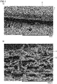
- Fig. 1 is photographs of a scanning electron microscope (SEM) of a cross section in a thickness direction of the nonwoven fabric of the present invention (Example 1 described later, Fig. 1(a) shows a 100-times magnified photograph, and Fig. 1(b) shows a 1000-times magnified photograph).
- the nonwoven fabric of the present invention has a fusion part 3 in which fibers 2 are partially fused (self-fused) to one another although being a nonwoven fabric 1 including fibers that contain a polymer having a Tg of greater than or equal to 50°C as a main component.
- the fiber fusion rate is preferably greater than or equal to 15%, more preferably greater than or equal to 20%, and furthermore preferably greater than or equal to 25%.
- the proportion of the parts where fibers are fused to one another occupied in the nonwoven fabric is extremely low and the strength becomes insufficient, and failures may occur in the handleability, such that the nonwoven fabric cannot be handled alone, in some cases.
- the fiber fusion rate of a nonwoven fabric is preferably less than or equal to 60%, and more preferably less than or equal to 50%.
- the above-described fiber fusion rate of a nonwoven fabric can be calculated, for example, by the following procedures.
- a SEM a 1000-times magnified photograph of the cross section in the thickness direction of the nonwoven fabric is taken, and from the photograph, a proportion of the number of the cut sections where fibers are fused to one another relative to the number of fiber cut sections (fiber cross sections) is determined by visual inspection.
- the proportion of the number of the cross sections where greater than or equal to two fibers are fused to one another, occupied in the total number of the fiber cross sections that can be found in each region is expressed as a percentage on the basis of the following equation:
- Fiber fusion rate (%) (the number of the cross sections where greater than or equal to two fibers are fused to one another) / (the total number of the fiber cross sections) ⁇ 100. Provided that the number of the fibers whose cross sections can be seen is counted in each photograph, and in a case where the number of fiber cross sections are less than or equal to 100, photographs to be observed are added so that the total number of the fiber cross sections exceeds 100.
- an average area of parts where fibers are fused is preferably less than or equal to 70 ⁇ m 2 , and more preferably less than or equal to 50 ⁇ m 2 .
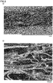
- a SEM photograph of a cross section in a thickness direction in a case where a nonwoven fabric formed by a melt blown method has been subjected to a post processing is shown in each of Figs. 6 to 8 .
- Fig. 6 shows SEM photographs in a case where calender processing has been performed as the post processing (Comparative Example 3 described later, Fig. 6(a) shows a 100-times magnified photograph, and Fig.
- FIG. 6(b) shows a 1000-times magnified photograph
- Fig. 7 shows SEM photographs in a case where emboss processing has been performed as the post processing (Comparative Example 2 described later
- Fig. 7(a) shows a 100-times magnified photograph
- Fig. 7(b) shows a 1000-times magnified photograph
- Fig. 8 shows SEM photographs in a case where spunlace processing has been performed as the post processing
- Fig. 8(a) shows a 100-times magnified photograph
- Fig. 8(b) shows a 1000-times magnified photograph.
- Figs. 8 shows SEM photographs in a case where spunlace processing has been performed as the post processing
- Fig. 8(a) shows a 100-times magnified photograph
- Fig. 8(b) shows a 1000-times magnified photograph
- the nonwoven fabric of the present invention can be clearly distinguished from the nonwoven fabric to which post processing such as calender processing, emboss processing, spunlace processing, or the like has been performed.
- the nonwoven fabric of the present invention has an average fiber diameter within the range of 1 to 10 ⁇ m.
- the nonwoven fabric of the present invention contains a fusion part where fibers are fused to one another, but even in the case, different from the case where calender processing has been performed (see Fig. 6(b) ), or the case where emboss processing has been performed (see Fig. 7(b) ), the fusion is to the extent that the fiber diameter can be discriminated ( Fig. 1(b) ), and the average fiber diameter can be calculated.
- the average fiber diameter of the nonwoven fabric of the present invention in a case where the average fiber diameter is less than 1 ⁇ m, the discharge amount is required to be decreased, and thus the productivity is lowered, in addition, the discharge pressure becomes unstable, and thread breakage or polymer lumps may be frequently generated and thus the formation of a web may become difficult. Further, in the nonwoven fabric of the present invention, in a case where the average fiber diameter exceeds 10 ⁇ m, the denseness may become poor. In particular, for the reason of achieving a balance between the production stability and the denseness, the average fiber diameter of the nonwoven fabric of the present invention is more preferably within the range of 1.2 to 9.5 ⁇ m, and particularly preferably within the range of 1.5 to 9.0 ⁇ m.
- the nonwoven fabric of the present invention includes fibers that contain a polymer having a Tg of greater than or equal to 50°C as a main component.
- fibers that contain a polymer having a Tg of greater than or equal to 50°C as a main component is referred to as fibers that contain a greater than or equal to 50% by mass of polymer having a Tg of greater than or equal to 50°C, and the content is preferably greater than or equal to 70% by mass, more preferably greater than or equal to 80% by mass, furthermore preferably greater than or equal to 90% by mass, and particularly preferably greater than or equal to 100% by mass.
- the nonwoven fabric of the present invention may contain greater than or equal to two different polymers having a Tg of greater than or equal to 50°C.
- Examples of the polymer used in the present invention and having a Tg of greater than or equal to 50°C include polyamide, polyphenylene sulfide, polyethylene terephthalate, and polycarbonate, and from the viewpoint of combining flame retardancy, heat resistance, and the like, amorphous polyetherimide (PEI) is particularly preferred.
- PEI amorphous polyetherimide
- the amorphous PEI used in the present invention is a polymer containing an aliphatic, alicyclic or aromatic ether unit and a cyclic imide as a repeating unit, and is not particularly limited as long as having amorphousness and melt formability. Further, as long as the amorphous PEI is in a range not inhibiting the effect of the present invention, a cyclic imide, and a structural unit other than an ether bond, for example, an aliphatic, alicyclic, or aromatic ester unit, an oxycarbonyl unit, and the like may be contained in the main chain of the amorphous PEI.
- a polymer represented by the following general formula is suitably used.
- R1 represents a divalent aromatic residue having 6 to 30 carbon atoms
- R2 represents a divalent organic group selected from the group consisting of a divalent aromatic residue having 6 to 30 carbon atoms, an alkylene group having 2 to 20 carbon atoms, a cycloalkylene group having 2 to 20 carbon atoms, and a polydiorganosiloxane group that is chain-stopped by an alkylene group having 2 to 8 carbon atoms.
- the melt viscosity at 330°C is preferably 100 to 3000 Pa ⁇ s.
- the melt viscosity of amorphous PEI at 330°C is less than 100 Pa ⁇ s, there may be a case where fiber dust, or resin particles called shots that occur due to the failure in formation of fibers are frequently generated during spinning.
- the melt viscosity of amorphous PEI at 330°C exceeds 3000 Pa ⁇ s, there may be a case where a trouble occurs during polymerization or granulation, for example, ultra-fine fibers are difficult to be formed, and oligomers are generated during polymerization.
- the melt viscosity at 330°C is preferably 200 to 2700 Pa ⁇ s, and more preferably 300 to 2500 Pa ⁇ s.
- the glass transition temperature is preferably greater than or equal to 200°C.
- the glass transition temperature is less than 200°C, there may be a case where the heat resistance of a nonwoven fabric to be obtained is poor.
- the glass transition temperature of amorphous PEI is higher, a nonwoven fabric excellent in the heat resistance can be obtained, therefore, this is preferred, but when the glass transition temperature is extremely high, the fused temperature may also become high, and thus a polymer may be decomposed during fusion.
- the glass transition temperature of the amorphous PEI is more preferably 200 to 230°C, and furthermore preferably 205 to 220°C.
- the molecular weight of the amorphous PEI used in the present invention is not particularly limited, and in consideration of the mechanical properties, the dimensional stability, or the processability of the fibers or nonwoven fabric to be obtained, the weight average molecular weight (Mw) is preferably 1000 to 80000.
- Mw weight average molecular weight
- the weight average molecular weight is preferably 2000 to 50000, and more preferably 3000 to 40000.
- amorphous PEI a condensate of 2,2-bis[4-(2,3-dicarboxyphenoxy)phenyl]propane dianhydride and m-phenylenediamine or p-phenylenediamine, which mainly has a structural unit represented by the following formula, is preferably used.
- This PEI is commercially available from SABIC Innovative Plastics under the trademark of "ULTEM”.
- the fibers containing a polymer having a Tg of greater than or equal to 50°C as a main component, which are included in the nonwoven fabric of the present invention, may contain an antioxidant, an antistatic agent, a radical inhibitor, a matting agent, an UV absorber, a flame retardant, an inorganic substance, and the like within the range of not impairing the effects of the present invention.
- a silicate such as talc, wollastonite, zeolite, sericite, mica, kaolin, clay, pyrophyllite, silica, bentonite, and a
- a terminal sequestering agent such as a mono- or di-epoxy compound, a mono- or poly-carbodiimide compound, a mono- or di-oxazoline compound, and a mono- or di-azirine compound may be contained.
- the nonwoven fabric of the present invention may include fibers other than the fibers that contain a polymer having a Tg of greater than or equal to 50°C as a main component, for example, fibers made of polyethylene, polypropylene, ethylene vinyl acetate, or the like within the range of not impairing the effects of the present invention.
- the content of the fibers that contain a polymer having a Tg of greater than or equal to 50°C as a main component is not particularly limited, and is preferably greater than or equal to 50% by mass, more preferably greater than or equal to 70% by mass, furthermore preferably greater than or equal to 90% by mass, and particularly preferably 100% by mass.
- the thickness of the nonwoven fabric of the present invention is not particularly limited, and is preferably within the range of 10 to 1000 ⁇ m, more preferably within the range of 15 to 500 ⁇ m, and particularly preferably within the range of 20 to 200 ⁇ m. In a case where the thickness of the nonwoven fabric is less than 10 ⁇ m, the strength may be lowered, and breakage may occur during processing, and further, in a case where the thickness of the nonwoven fabric of the present invention exceeds 1000 ⁇ m, the formation of a web may become difficult.
- the air permeability is preferably greater than or equal to 10 cc/cm 2 /sec, and more preferably greater than or equal to 20 cc/cm 2 /sec, and further preferably less than or equal to 130 cc/cm 2 /sec, and more preferably less than or equal to 120 cc/cm 2 /sec.
- the nonwoven fabric of the present invention can be suitably used for the application of a filter or the like.
- the basis weight of the nonwoven fabric of the present invention is not particularly limited, and is preferably within the range of 10 to 1000 g/m 2 , and more preferably within the range of 15 to 500 g/m 2 . In a case where the basis weight of the nonwoven fabric is less than 10 g/m 2 , the strength may be lowered, and breakage may occur during processing, and further, in a case where the basis weight of the nonwoven fabric exceeds 1000 g/m 2 , the case is not preferred from the viewpoint of the productivity.
- the present invention is also to provide a method for producing the above-described nonwoven fabric of the present invention.
- the above-described nonwoven fabric of the present invention is a nonwoven fabric including fibers that contain a polymer having a Tg of greater than or equal to 50°C as a main component, and having a vertical strength of greater than or equal to 1 N/5 cm per 1 g/m 2 .
- the nonwoven fabric of the present invention may be a nonwoven fabric produced by the method for producing a nonwoven fabric of the present invention, or may be a nonwoven fabric not produced by the method for producing a nonwoven fabric of the present invention, but a nonwoven fabric produced by the method for producing a nonwoven fabric of the present invention is preferred.
- the method for producing a nonwoven fabric of the present invention is characterized in that a melt blown method is performed while maintaining a temperature in at least one of the following (1) and (2) at a temperature higher than the Tg of the polymer to be a main component by greater than or equal to 10°C.
- the temperature is maintained at a temperature higher than the Tg of the polymer having the highest Tg by greater than or equal to 10°C.
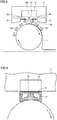
- Figs. 2 and 3 are schematic diagrams for illustrating a principle of the method for producing a nonwoven fabric of the present invention.
- Fig. 2 shows a state that a melt blown method is performed by using a melt blown device 11, and after polymer fibers 13 are discharged (spun) from a spinning nozzle 12 of melt blown device 11, discharged (spun) polymer fibers 13 are collected by a rotating roll 14, and a web (that is in a sheet shape obtained by piling up fibers) 15 is formed.
- Hot air (primary air) 16 for spinning is discharged together with polymer fibers 13 from spinning nozzle 12 of melt blown device 11, and flows along the curved surface of roll 14.
- the present inventors found that as cold air flows as accompanying flow 17 toward spinning nozzle 12, polymer fibers 13 discharged from a tip 12a of spinning nozzle 12 are rapidly cooled before reaching a surface (collection surface of spun fibers) 14a of roll 14, and thus web 15 having low strength and poor handleability is formed. For this reason, conventionally, it has been required to perform a post processing such as calender processing, emboss processing, or spunlace (hydroentangle) processing to impart strength to a web and to form a nonwoven fabric.
- a post processing such as calender processing, emboss processing, or spunlace (hydroentangle) processing to impart strength to a web and to form a nonwoven fabric.
- the temperature in either space A or point B is only required to be maintained at a temperature higher than the Tg of the polymer by greater than or equal to 10°C, but the temperatures in both of space A and point B may be maintained at a temperature higher than the Tg of the polymer by greater than or equal to 15°C. Further, as in the example shown in Fig. 3 , a part of space A and a part of point B may be overlapped.
- the nonwoven fabric of the present invention that contains a polymer having a Tg of greater than or equal to 50°C as a main component and has sufficient strength obtained by fusing fibers to one another can be produced without performing a post processing such as calender processing, emboss processing, or spunlace processing (that is, web 15 collected by roll 14 can be used as it is as the nonwoven fabric).
- a temperature in hemispherical space A of radius x that is 0.5 ⁇ collection distance d around a nozzle tip relative to the collection distance d between tip 12a of spinning nozzle 12 and collection surface 14a of spun fibers 13 is higher than the Tg by greater than or equal to 10°C
- Radius x in hemispherical space A around tip 12a of spinning nozzle 12 is preferably 3 to 12 cm, and particularly preferably 5 cm.
- a temperature in space A can be measured by arranging, for example, a thermocouple-type thermometer as a thermometer at any position on a curved surface constituting a hemisphere assumed as a boundary of space A.
- the temperature in a space around point B is not particularly limited.
- the temperature in at least one of space A and point B is maintained so as to be at a temperature higher than the Tg of a polymer by greater than or equal to 10°C (more preferably within the range of 15 to 60°C).
- a temperature in at least one of space A and point B is at a temperature less than or equal to the Tg of a polymer, or is less than 10°C even if being higher than the Tg, the effect of preventing the cooling of the spun fibers by the accompanying flow is insufficient, and thus a nonwoven fabric having low strength and poor handleability may be produced.
- Fig. 4 is a diagram schematically showing one preferred example of the method for producing a nonwoven fabric of the present invention.
- a hot air injection device 21 is arranged in the vicinity of tip 12a of spinning nozzle 12 so as to blow hot air (for the primary air described above, this hot air is referred to as "secondary air") 22 toward tip 12a of spinning nozzle 12.
- hot air injection device 21 is not particularly limited, and hot air injection device 21 in a shape of continuously forming a circumference surrounding tip 12a of spinning nozzle 12 may be arranged so that a blowing tip is directed toward tip 12a of spinning nozzle 12, or multiple hot air injection devices 21 may be arranged around tip 12a so that a blowing tip is directed toward tip 12a of spinning nozzle 12.
- hot air injection device 21 a conventionally known appropriate hot air injection device can be used without any particular limitation.
- the temperature of secondary air 22 injected so as to be blown into tip 12a of spinning nozzle 12 by hot air injection device 21 is not particularly limited as long as the temperature in at least one of the above (1) and (2) (in particular, a space of the above-described (1)) can be maintained at a temperature higher than the Tg of a polymer by greater than or equal to 30°C, and is preferably at a temperature higher than the Tg of a polymer by 35 to 70°C and more preferably at a temperature higher than the Tg of a polymer by 35 to 60°C.
- the temperature of secondary air 22 is at a temperature higher than the Tg of a polymer by less than 30°C, it becomes difficult to maintain the temperature in at least one of the above-described (1) and (2) (in particular, a space of the above-described (1)), and further, there is a tendency that the fiber fusion is small and the nonwoven fabric strength is weak. Furthermore, in a case where the temperature of secondary air 22 is higher than the Tg of a polymer by exceeding 70°C, there is a tendency that the fiber fusion is increased and a paper-like nonwoven fabric is obtained.
- the flow rate of secondary air 22 is also not particularly limited as long as the temperature in at least one of the above (1) and (2) (in particular, a space of the above-described (1)) can be maintained at a temperature higher than the Tg of a polymer by greater than or equal to 10°C, and is in order not to disturb the flow of the primary air, preferably within the range of 3 to 12 Nm 3 /m, and more preferably within the range of 4 to 10 Nm 3 /m.
- Fig. 5 is a diagram schematically showing another preferred example of the method for producing a nonwoven fabric of the present invention.
- a cover 31 At least a part of a space between tip 12a of spinning nozzle 12 and collection surface 14a of spun fibers is covered with a cover 31.
- the primary air discharged from tip 12a of the spinning nozzle 12 stays in the space covered with cover 31 as circulation air 32, and thus the primary air discharged from tip 12a of spinning nozzle 12 is not rapidly cooled by the accompanying flow as in a case of not being covered with cover 31.
- cover 31 does not need to cover throughout between tip 12a of spinning nozzle 12 and collection surface 14a of spun fibers. As in the example shown in Fig. 5 , it is preferred that cover 31 is arranged so as to cover throughout between tip 12a of spinning nozzle 12 and collection surface 14a of spun fibers.
- a material for forming such cover 31 is not particularly limited as long as having heat resistance to the extent that the cover is not deteriorated due to the temperature of primary air, for example, a metal such as steel use stainless (SUS), aluminum, and copper can be mentioned, and SUS is preferred from the viewpoint of the durability, the processability, and the heat resistance.
- SUS steel use stainless
- a melt blown method is performed, and processes, conditions, and the like that are similar to those in a conventional melt blown method can be suitably adopted except that a post processing such as calender processing, emboss processing, or spunlace processing is not performed.
- spinning conditions for example, a spinning temperature of 300 to 500°C, a hot air temperature (primary air temperature) of 300 to 500°C, and an amount of air of 5 to 25 Nm 3 per 1 m of nozzle length can be mentioned as suitable examples, but of course, the spinning conditions are not limited to these examples.
- the volume of a nonwoven fabric was measured using [basis weight of the nonwoven fabric] and [thickness of the nonwoven fabric], and from these results, the density of the nonwoven fabric was calculated.
- the nonwoven fabric was cut into a piece with a width of 5 cm, and the piece was extended at a tensile rate of 10 cm/min by using an autograph manufactured by Shimadzu Corporation in accordance with JIS L 1906, and the load value at the time of breaking was defined as the vertical strength.
- the temperature dependency of loss tangent (tan ⁇ ) was measured at a frequency of 10 Hz and at a temperature rise rate of 10°C/min, and the glass transition temperature was determined from the peak temperature.
- the peak temperature of tan ⁇ means a temperature at which the first derivative value of the amount of change to the temperature of the value of tan ⁇ becomes zero.
- Fiber cross sections a proportion of the number of cut sections where fibers are fused to one another relative to the number of fiber cut sections (fiber cross sections) was determined by visual inspection.
- the number of the fibers whose cross sections can be seen is counted in each photograph, and in a case where the number of fiber cross sections are less than or equal to 100, photographs to be observed were added so that the total number of the fiber cross sections exceeds 100.
- the nonwoven fabric was photographed with magnification by a scanning electron microscope, the diameters of arbitrary 100 fibers were measured, the average value was calculated, and defined as the average fiber diameter.
- the thickness was measured at five positions in each sample piece with a digital thickness measuring device having a diameter of 16 mm and a load of 20 gf/cm 2 (B1 type, manufactured by Toyo Seiki Seisaku-Sho, Ltd.), and the average value of the thicknesses at 15 positions was defined as the thickness of the sheet.
- the air permeability was measured in accordance with a fragile form method of JIS L 1913 "Test methods for nonwovens".
- a hot air injection device as in the example shown in Fig. 4 was arranged so that hot air (secondary air) blows into a tip of the spinning nozzle of the melt blown device, and hot air (secondary air) at a temperature of 260°C was blown at a flow rate of 2 Nm 3 toward the tip of the spinning nozzle.
- a thermometer AD-5601A (manufactured by A&D Company, Limited)
- thermometer AD-5601A (manufactured by A&D Company, Limited) arranged so as to be positioned 1 cm from a collection surface on the straight line relative to the direct distance d between the tip of the spinning nozzle and the collection surface of the spun fibers was 242°C (that is, point B was maintained at a temperature higher than 215°C that is a glass transition temperature of the amorphous PEI by 27°C).
- point B was maintained at a temperature higher than 215°C that is a glass transition temperature of the amorphous PEI by 27°C.
- a nonwoven fabric was obtained in the similar manner as in Example 2 except that the basis weight was changed to 10 g/m 2 .
- a hot air injection device as in the example shown in Fig. 4 was arranged so that hot air (secondary air) blows into a tip of the spinning nozzle of the melt blown device, and hot air (secondary air) at a temperature of 210°C was blown at a flow rate of 2 Nm 3 toward the tip of the spinning nozzle.
- a thermometer AD-5601A (manufactured by A&D Company, Limited)
- thermometer AD-5601A (manufactured by A&D Company, Limited) arranged so as to be positioned 1 cm from the collection surface on the straight line relative to the direct distance d between the tip of the spinning nozzle and a collection surface of the spun fibers was 192°C (that is, point B was maintained at a temperature higher than 135°C that is a glass transition temperature of the amorphous polycarbonate by 57°C).
- the nonwoven fabric obtained in Comparative Example 1 was subjected to emboss processing as the post processing with an embossing roll having a lattice pattern under the conditions of a roll temperature of 180°C, a linear pressure of 50 kg/cm, and a speed of 1 m/min.
- an embossing roll having a lattice pattern under the conditions of a roll temperature of 180°C, a linear pressure of 50 kg/cm, and a speed of 1 m/min.
- a SEM photograph of a cross section in a thickness direction of the obtained nonwoven fabric a 100-times magnified photograph is shown in Fig. 7(a)
- a 1000-times magnified photograph is shown in Fig. 7(b) .
- the nonwoven fabric obtained in Comparative Example 1 was subjected to calender processing as the post processing under the conditions of a roll temperature of 180°C, a linear pressure of 216 kg/cm, and a speed of 3.2 m/min.
- a SEM photograph of a cross section in a thickness direction of the obtained nonwoven fabric a 100-times magnified photograph is shown in Fig. 6(a) , and a 1000-times magnified photograph is shown in Fig. 6(b) .
- the nonwoven fabric obtained in Comparative Example 1 was subjected to hydroentangling as the post processing at a speed of 5.0 m/min using a nozzle having a hole diameter of 0.1 mm ⁇ with hydroentangling treatment at three stages of 0.5 MPa, 2.0 MPa, and 2.5 MPa.
- a SEM photograph of a cross section in a thickness direction of the obtained nonwoven fabric a 100-times magnified photograph is shown in Fig. 8(a) , and a 1000-times magnified photograph is shown in Fig. 8(b) .
- a nonwoven fabric was obtained under the similar conditions as in Example 2 except that the temperature of the hot air (secondary air) was changed to 240°C.
- Example 1 Example 2
- Example 3 Example 4 (Raw material forming nonwoven fabric and production conditions) Polymer composition of fibers PEI PEI PEI PC Melt viscosity (Pa ⁇ s): 330°C (300°C in Example 4) 500 900 900 100 Glass transition temperature (°C) 215 215 215 135 Spinning temperature (°C) 390 420 420 340 Hot air injection device Yes Yes Yes Yes Hot air (secondary air) temperature (°C) 260 260 210 Collection distance (cm) 10 10 10 Temperature in space A (°C) 235 253 253 185 Temperature in point B (°C) 242 261 261 192 Post processing No No No No No (Performance of nonwoven fabric) Density (g/cm 3 ) 0.147 0.132 0.103 0.295 Proportion of parts with a density exceeding 0.4 g/cm 3 (%) 0 0 0 1.4 Vertical strength per 1 g/m 2 (N
- the nonwoven fabric of the present invention is excellent in the handleability in spite of having a low density, therefore, not only can be used in combination with various substrates and other nonwoven fabrics, but also can be used for filters and the like that are required to have permeability.
- Nonwoven fabric 1: Nonwoven fabric, 2: fibers, 3: fusion part, 11: melt blown device, 12: spinning nozzle, 12a: air outlet, 13: spun amorphous polymer-based fibers, 14: roll, 14a: roll receiving surface, 15: nonwoven fabric, 16: primary air, 17: accompanying flow, 21: hot air injection device, 22: secondary air, 31: cover, 32: circulation air
Landscapes
- Engineering & Computer Science (AREA)
- Textile Engineering (AREA)
- Mechanical Engineering (AREA)
- Chemical & Material Sciences (AREA)
- Chemical Kinetics & Catalysis (AREA)
- Nonwoven Fabrics (AREA)
- General Chemical & Material Sciences (AREA)
Abstract
Description
- The present invention relates to a nonwoven fabric, and a method for producing the nonwoven fabric.
- In recent years, a nonwoven fabric made of ultra-fine fibers produced by a melt blown method or the like has been developed, and is used for various applications. With respect to a nonwoven fabric containing a polymer having a glass transition temperature (Tg) of less than 50°C, such as polypropylene and polyethylene, a nonwoven fabric excellent in the handleability, in which fibers are fused to one another, can be obtained without performing a post processing such as emboss processing, calender processing, or spunlace processing.
- However, with respect to a nonwoven fabric containing a polymer that has a Tg of greater than or equal to 50°C, unless the fibers are fused to one another or three-dimensionally entangled with one another by performing a post processing, the strength as a nonwoven fabric is weak, therefore, the handleability is poor, and further, there have been problems that fluff is prone to occur, and the like.
- Accordingly, for such a nonwoven fabric, in general, a method for solving the problems has been taken by performing a post processing (for example, Japanese Patent Laying-Open No.
2012-41644 - However, in the nonwoven fabric that has been subjected to a post processing as described above, at least some parts of the nonwoven fabric have a high density, as a result there may be a case where the performances of the air permeability and the like are affected, therefore, it has been desired to develop a nonwoven fabric that is excellent in the handleability even though there are few high-density parts.
- PTD 1: Japanese Patent Laying-Open No.
2012-41644 - The present invention has been made to solve the above problems, and an object of the present invention is to provide a nonwoven fabric having sufficient strength to be handled alone and including fibers that contain a polymer having a Tg of greater than or equal to 50°C as a main component without performing a post processing such as emboss processing, calender processing, or spunlace processing, and a method for producing the nonwoven fabric.
- The nonwoven fabric of the present invention is a nonwoven fabric including fibers that contain a polymer having a glass transition temperature of greater than or equal to 50°C as a main component, having a vertical strength of greater than or equal to 1 N/5 cm per 1 g/m2, and satisfying the following conditions (1) and (2):
- (1) a density is 0.01 to 0.4 g/cm3; and
- (2) a proportion of parts with a density exceeding 0.4 g/cm3 is less than or equal to 3% in a cross section in a thickness direction.
- It is preferred that the nonwoven fabric of the present invention has a fiber fusion rate of greater than or equal to 15% in a cross section in a thickness direction, and an average area of parts where fibers are fused of less than or equal to 70 µm2.
- The nonwoven fabric of the present invention preferably has an average fiber diameter of 1 to 10 µm.
- The present invention is also to provide a method for producing the above-described nonwoven fabric of the present invention, in which a melt blown method is performed while maintaining a temperature in at least one of (1) a hemispherical space of 0.5 × collection distance d around a nozzle tip relative to the collection distance d between the tip of a spinning nozzle and a collection surface of spun fibers, and (2) a point of 1 cm from the collection surface on the straight line relative to the collection distance d between the tip of the spinning nozzle and the collection surface of spun fibers at a temperature higher than the glass transition temperature by greater than or equal to 10°C.
- According to the present invention, a nonwoven fabric having sufficient strength to be handled alone and including fibers that contain a polymer having a Tg of greater than or equal to 50°C as a main component without performing a post processing such as emboss processing, calender processing, or spunlace processing, and a method for producing the nonwoven fabric can be provided.
-
-
Fig. 1 is a scanning electron microscope (SEM) photograph of a cross section in a thickness direction of a nonwoven fabric of the present invention. -
Fig. 2 is a schematic diagram for illustrating a principle of a method for producing a nonwoven fabric of the present invention. -
Fig. 3 is a schematic diagram for illustrating a principle of the method for producing a nonwoven fabric of the present invention. -
Fig. 4 is a diagram schematically showing one preferred example of the method for producing a nonwoven fabric of the present invention. -
Fig. 5 is a diagram schematically showing another preferred example of the method for producing a nonwoven fabric of the present invention. -
Fig. 6 is a SEM photograph of a cross section in a thickness direction in a case where a nonwoven fabric is formed by a melt blown method using a polymer having a Tg of greater than or equal to 50°C, and then the formed nonwoven fabric is subjected to calender processing as the post processing. -
Fig. 7 is a SEM photograph of a cross section in a thickness direction in a case where a nonwoven fabric is formed by a melt blown method using a polymer having a Tg of greater than or equal to 50°C, and then the formed nonwoven fabric is subjected to emboss processing as the post processing. -
Fig. 8 is a SEM photograph of a cross section in a thickness direction in a case where a nonwoven fabric is formed by a melt blown method using a polymer having a Tg of greater than or equal to 50°C, and then the formed nonwoven fabric is subjected to spunlace processing as the post processing. - The nonwoven fabric of the present invention has a vertical strength (strength in a vertical direction (a direction of flow in producing the nonwoven fabric)) per 1 g/m2 of greater than or equal to 1 N/5 cm. According to the present invention, a nonwoven fabric having sufficient strength to be handled alone as a nonwoven fabric can be obtained without performing a post processing such as calender processing, emboss processing, or spunlace processing, which generates a part partially with a high density. The strength of the nonwoven fabric of the present invention is more preferably greater than or equal to 1.2 N/5 cm, and furthermore preferably 1.5 N/5 cm. In a case where a nonwoven fabric is formed by a conventional melt blown method, and the formed nonwoven fabric is not subjected to a post processing such as calender processing, emboss processing, or spunlace processing (Comparative Example 1 described later), the vertical strength per 1 g/m2 becomes significantly poor, but even as compared with such a case, the nonwoven fabric of the present invention is a nonwoven fabric significantly excellent in the handleability.
- In addition, the nonwoven fabric of the present invention is a nonwoven fabric having a density of 0.01 to 0.4 g/cm3. When the density is greater than or equal to 0.01 g/cm3, preferred form and properties as a nonwoven fabric can be maintained, and when the density is less than or equal to 0.4 g/cm3, desired performance such as high permeability can be easily obtained in the nonwoven fabric. The density of the nonwoven fabric of the present invention is preferably less than or equal to 0.35 g/cm3, and more preferably less than or equal to 0.3 g/cm3, and preferably greater than or equal to 0.1 g/cm3, and more preferably greater than or equal to 0.11 g/cm3.
- In addition, in the nonwoven fabric of the present invention, a proportion of parts with a density exceeding 0.4 g/cm3 is less than or equal to 3%. In a case where the proportion of parts with a density exceeding 0.4 g/cm3 exceeds 3%, unevenness is generated on the nonwoven fabric, and as a result, failures that the air permeability is affected, uneven strength is generated, and the like may occur in some cases. The proportion of parts with a density exceeding 0.4 g/cm3 is more preferably less than or equal to 2.5%, and furthermore preferably less than or equal to 2%.
- The proportion of parts with a density exceeding 0.4 g/cm3 in the nonwoven fabric described above is determined as follows. Using a SEM, a 100-times magnified photograph of the cross section in the thickness direction of the nonwoven fabric is taken, a straight line of 10 mm of the photograph is observed in the width direction by visual inspection, the length occupied by the parts with a density exceeding 0.4 g/cm3 is measured in this straight line, and the proportion is determined by the following equation:

- Herein,
Fig. 1 is photographs of a scanning electron microscope (SEM) of a cross section in a thickness direction of the nonwoven fabric of the present invention (Example 1 described later,Fig. 1(a) shows a 100-times magnified photograph, andFig. 1(b) shows a 1000-times magnified photograph). As shown inFig. 1 , the nonwoven fabric of the present invention has afusion part 3 in whichfibers 2 are partially fused (self-fused) to one another although being anonwoven fabric 1 including fibers that contain a polymer having a Tg of greater than or equal to 50°C as a main component. Herein, in a cross section in a thickness direction ofnonwoven fabric 1 of the present invention, the fiber fusion rate is preferably greater than or equal to 15%, more preferably greater than or equal to 20%, and furthermore preferably greater than or equal to 25%. In a case where the fiber fusion rate is less than 15%, the proportion of the parts where fibers are fused to one another occupied in the nonwoven fabric is extremely low and the strength becomes insufficient, and failures may occur in the handleability, such that the nonwoven fabric cannot be handled alone, in some cases. In addition, if the fiber fusion rate is extremely high, there may be a case where a paper-like seat is formed, the air permeability is affected, or the like, therefore, the fiber fusion rate of a nonwoven fabric is preferably less than or equal to 60%, and more preferably less than or equal to 50%. - The above-described fiber fusion rate of a nonwoven fabric can be calculated, for example, by the following procedures. At first, using a SEM, a 1000-times magnified photograph of the cross section in the thickness direction of the nonwoven fabric is taken, and from the photograph, a proportion of the number of the cut sections where fibers are fused to one another relative to the number of fiber cut sections (fiber cross sections) is determined by visual inspection. The proportion of the number of the cross sections where greater than or equal to two fibers are fused to one another, occupied in the total number of the fiber cross sections that can be found in each region is expressed as a percentage on the basis of the following equation:
- Fiber fusion rate (%) = (the number of the cross sections where greater than or equal to two fibers are fused to one another) / (the total number of the fiber cross sections) × 100. Provided that the number of the fibers whose cross sections can be seen is counted in each photograph, and in a case where the number of fiber cross sections are less than or equal to 100, photographs to be observed are added so that the total number of the fiber cross sections exceeds 100. Further, in the parts where fibers are in contact with one another, there are a part where fibers are simply in contact with one another without fusing to one another and a part where fibers are bonded with fusing to one another, and since the nonwoven fabric is cut for the SEM photography, the fibers that are simply in contact with one another are separated due to the stress of each fiber in the cross section. Therefore, in the SEM photograph, it can be determined that fibers, which are in contact with one another, are fused to one another.
- Further, in the nonwoven fabric of the present invention, an average area of parts where fibers are fused is preferably less than or equal to 70 µm2, and more preferably less than or equal to 50 µm2. Herein, as a conventional example, a SEM photograph of a cross section in a thickness direction in a case where a nonwoven fabric formed by a melt blown method has been subjected to a post processing is shown in each of
Figs. 6 to 8 .Fig. 6 shows SEM photographs in a case where calender processing has been performed as the post processing (Comparative Example 3 described later,Fig. 6(a) shows a 100-times magnified photograph, andFig. 6(b) shows a 1000-times magnified photograph),Fig. 7 shows SEM photographs in a case where emboss processing has been performed as the post processing (Comparative Example 2 described later,Fig. 7(a) shows a 100-times magnified photograph, andFig. 7(b) shows a 1000-times magnified photograph), andFig. 8 shows SEM photographs in a case where spunlace processing has been performed as the post processing (Comparative Example 4 described later,Fig. 8(a) shows a 100-times magnified photograph, andFig. 8(b) shows a 1000-times magnified photograph). As is prominent inFigs. 6(b) and7(b) , in a nonwoven fabric to which calender processing or emboss processing has been performed as the post processing, a large number of parts where fibers are fused to one another to the extent of the state that discrimination of the fiber diameter becomes difficult are formed, and the average area of parts where fibers are fused exceeds 70 µm2. Since the average area of parts where fibers are fused is less than or equal to 70 µm2, the nonwoven fabric of the present invention can be distinguished from the nonwoven fabric to which calender processing or emboss processing has been performed as the post processing, as is prominent inFigs. 6(b) and7(b) . On the other hand, as shown inFig. 8 , in the nonwoven fabric to which spunlace processing has been performed, the parts where fibers are fused are extremely few, and the fiber fusion rate becomes less than 15%. As described above, when the fiber fusion rate in a cross section in a thickness direction is greater than or equal to 15%, and an average area of parts where fibers are fused is less than or equal to 70 µm2, the nonwoven fabric of the present invention can be clearly distinguished from the nonwoven fabric to which post processing such as calender processing, emboss processing, spunlace processing, or the like has been performed. - It is preferred that the nonwoven fabric of the present invention has an average fiber diameter within the range of 1 to 10 µm. As described above, it is preferred that the nonwoven fabric of the present invention contains a fusion part where fibers are fused to one another, but even in the case, different from the case where calender processing has been performed (see
Fig. 6(b) ), or the case where emboss processing has been performed (seeFig. 7(b) ), the fusion is to the extent that the fiber diameter can be discriminated (Fig. 1(b) ), and the average fiber diameter can be calculated. In the nonwoven fabric of the present invention, in a case where the average fiber diameter is less than 1 µm, the discharge amount is required to be decreased, and thus the productivity is lowered, in addition, the discharge pressure becomes unstable, and thread breakage or polymer lumps may be frequently generated and thus the formation of a web may become difficult. Further, in the nonwoven fabric of the present invention, in a case where the average fiber diameter exceeds 10 µm, the denseness may become poor. In particular, for the reason of achieving a balance between the production stability and the denseness, the average fiber diameter of the nonwoven fabric of the present invention is more preferably within the range of 1.2 to 9.5 µm, and particularly preferably within the range of 1.5 to 9.0 µm. - The nonwoven fabric of the present invention includes fibers that contain a polymer having a Tg of greater than or equal to 50°C as a main component.
- In the present invention, the expression "fibers that contain a polymer having a Tg of greater than or equal to 50°C as a main component" is referred to as fibers that contain a greater than or equal to 50% by mass of polymer having a Tg of greater than or equal to 50°C, and the content is preferably greater than or equal to 70% by mass, more preferably greater than or equal to 80% by mass, furthermore preferably greater than or equal to 90% by mass, and particularly preferably greater than or equal to 100% by mass.
- In addition, when the total of the polymers having a Tg of greater than or equal to 50°C is greater than or equal to 50% by mass, the nonwoven fabric of the present invention may contain greater than or equal to two different polymers having a Tg of greater than or equal to 50°C.
- Examples of the polymer used in the present invention and having a Tg of greater than or equal to 50°C include polyamide, polyphenylene sulfide, polyethylene terephthalate, and polycarbonate, and from the viewpoint of combining flame retardancy, heat resistance, and the like, amorphous polyetherimide (PEI) is particularly preferred.
- The amorphous PEI used in the present invention is a polymer containing an aliphatic, alicyclic or aromatic ether unit and a cyclic imide as a repeating unit, and is not particularly limited as long as having amorphousness and melt formability. Further, as long as the amorphous PEI is in a range not inhibiting the effect of the present invention, a cyclic imide, and a structural unit other than an ether bond, for example, an aliphatic, alicyclic, or aromatic ester unit, an oxycarbonyl unit, and the like may be contained in the main chain of the amorphous PEI.
- As the amorphous PEI used in the present invention, a polymer represented by the following general formula is suitably used. Provided that in the formula, R1 represents a divalent aromatic residue having 6 to 30 carbon atoms, and R2 represents a divalent organic group selected from the group consisting of a divalent aromatic residue having 6 to 30 carbon atoms, an alkylene group having 2 to 20 carbon atoms, a cycloalkylene group having 2 to 20 carbon atoms, and a polydiorganosiloxane group that is chain-stopped by an alkylene group having 2 to 8 carbon atoms.

- In addition, in the amorphous PEI used in the present invention, the melt viscosity at 330°C is preferably 100 to 3000 Pa·s. When the melt viscosity of amorphous PEI at 330°C is less than 100 Pa·s, there may be a case where fiber dust, or resin particles called shots that occur due to the failure in formation of fibers are frequently generated during spinning. Further, when the melt viscosity of amorphous PEI at 330°C exceeds 3000 Pa·s, there may be a case where a trouble occurs during polymerization or granulation, for example, ultra-fine fibers are difficult to be formed, and oligomers are generated during polymerization. The melt viscosity at 330°C is preferably 200 to 2700 Pa·s, and more preferably 300 to 2500 Pa·s.
- In the amorphous PEI used in the present invention, the glass transition temperature is preferably greater than or equal to 200°C. When the glass transition temperature is less than 200°C, there may be a case where the heat resistance of a nonwoven fabric to be obtained is poor. Further, as the glass transition temperature of amorphous PEI is higher, a nonwoven fabric excellent in the heat resistance can be obtained, therefore, this is preferred, but when the glass transition temperature is extremely high, the fused temperature may also become high, and thus a polymer may be decomposed during fusion. The glass transition temperature of the amorphous PEI is more preferably 200 to 230°C, and furthermore preferably 205 to 220°C.
- The molecular weight of the amorphous PEI used in the present invention is not particularly limited, and in consideration of the mechanical properties, the dimensional stability, or the processability of the fibers or nonwoven fabric to be obtained, the weight average molecular weight (Mw) is preferably 1000 to 80000. When amorphous PEI having a high molecular weight is used, the amorphous PEI is excellent in terms of the fiber strength, the heat resistance, and the like, therefore, this is preferred, but from the viewpoint of the cost for producing a resin, the cost for forming into small fibers, and the like, the weight average molecular weight is preferably 2000 to 50000, and more preferably 3000 to 40000.
- In the present invention, from the viewpoint of the amorphousness, the melt formability, and the cost, as the amorphous PEI, a condensate of 2,2-bis[4-(2,3-dicarboxyphenoxy)phenyl]propane dianhydride and m-phenylenediamine or p-phenylenediamine, which mainly has a structural unit represented by the following formula, is preferably used. This PEI is commercially available from SABIC Innovative Plastics under the trademark of "ULTEM".

- The fibers containing a polymer having a Tg of greater than or equal to 50°C as a main component, which are included in the nonwoven fabric of the present invention, may contain an antioxidant, an antistatic agent, a radical inhibitor, a matting agent, an UV absorber, a flame retardant, an inorganic substance, and the like within the range of not impairing the effects of the present invention. As the specific examples of the inorganic substance, carbon nanotube, fullerene, a silicate such as talc, wollastonite, zeolite, sericite, mica, kaolin, clay, pyrophyllite, silica, bentonite, and alumina silicate, a metal oxide such as silicon oxide, magnesium oxide, alumina, zirconium oxide, titanium oxide, and iron oxide, a carbonate such as calcium carbonate, magnesium carbonate, and dolomite, a sulfate such as calcium sulfate, and barium sulfate, a hydroxide such as calcium hydroxide, magnesium hydroxide, and aluminum hydroxide, glass beads, glass flakes, glass powder, ceramic beads, boron nitride, silicon carbide, carbon black, graphite, and the like are used. Further, for the purpose of improving the hydrolysis resistance of fibers, a terminal sequestering agent such as a mono- or di-epoxy compound, a mono- or poly-carbodiimide compound, a mono- or di-oxazoline compound, and a mono- or di-azirine compound may be contained.
- Furthermore, the nonwoven fabric of the present invention may include fibers other than the fibers that contain a polymer having a Tg of greater than or equal to 50°C as a main component, for example, fibers made of polyethylene, polypropylene, ethylene vinyl acetate, or the like within the range of not impairing the effects of the present invention. The content of the fibers that contain a polymer having a Tg of greater than or equal to 50°C as a main component is not particularly limited, and is preferably greater than or equal to 50% by mass, more preferably greater than or equal to 70% by mass, furthermore preferably greater than or equal to 90% by mass, and particularly preferably 100% by mass.
- The thickness of the nonwoven fabric of the present invention is not particularly limited, and is preferably within the range of 10 to 1000 µm, more preferably within the range of 15 to 500 µm, and particularly preferably within the range of 20 to 200 µm. In a case where the thickness of the nonwoven fabric is less than 10 µm, the strength may be lowered, and breakage may occur during processing, and further, in a case where the thickness of the nonwoven fabric of the present invention exceeds 1000 µm, the formation of a web may become difficult.
- In addition, in the nonwoven fabric of the present invention, the air permeability is preferably greater than or equal to 10 cc/cm2/sec, and more preferably greater than or equal to 20 cc/cm2/sec, and further preferably less than or equal to 130 cc/cm2/sec, and more preferably less than or equal to 120 cc/cm2/sec. By setting the air permeability within the range described above, the nonwoven fabric of the present invention can be suitably used for the application of a filter or the like.
- In addition, the basis weight of the nonwoven fabric of the present invention is not particularly limited, and is preferably within the range of 10 to 1000 g/m2, and more preferably within the range of 15 to 500 g/m2. In a case where the basis weight of the nonwoven fabric is less than 10 g/m2, the strength may be lowered, and breakage may occur during processing, and further, in a case where the basis weight of the nonwoven fabric exceeds 1000 g/m2, the case is not preferred from the viewpoint of the productivity.
- The present invention is also to provide a method for producing the above-described nonwoven fabric of the present invention. Note that the above-described nonwoven fabric of the present invention is a nonwoven fabric including fibers that contain a polymer having a Tg of greater than or equal to 50°C as a main component, and having a vertical strength of greater than or equal to 1 N/5 cm per 1 g/m2. As long as the density is 0.01 to 0.4 g/cm3, and the proportion of parts with a density exceeding 0.4 g/cm3 is less than or equal to 3% in a cross section in a thickness direction, the nonwoven fabric of the present invention may be a nonwoven fabric produced by the method for producing a nonwoven fabric of the present invention, or may be a nonwoven fabric not produced by the method for producing a nonwoven fabric of the present invention, but a nonwoven fabric produced by the method for producing a nonwoven fabric of the present invention is preferred.
- The method for producing a nonwoven fabric of the present invention is characterized in that a melt blown method is performed while maintaining a temperature in at least one of the following (1) and (2) at a temperature higher than the Tg of the polymer to be a main component by greater than or equal to 10°C.
- (1) A hemispherical space of 0.5 × collection distance d around a nozzle tip relative to the collection distance d between the tip of a spinning nozzle and a collection surface of spun fibers.
- (2) A point of 1 cm from the collection surface on the straight line relative to the collection distance d between the tip of the spinning nozzle and the collection surface of spun fibers.
- Note that in a case where greater than or equal to two different kinds of polymers having a Tg of greater than or equal to 50°C are used, the temperature is maintained at a temperature higher than the Tg of the polymer having the highest Tg by greater than or equal to 10°C.
- Herein,
Figs. 2 and 3 are schematic diagrams for illustrating a principle of the method for producing a nonwoven fabric of the present invention.Fig. 2 shows a state that a melt blown method is performed by using a melt blowndevice 11, and afterpolymer fibers 13 are discharged (spun) from a spinningnozzle 12 of melt blowndevice 11, discharged (spun)polymer fibers 13 are collected by arotating roll 14, and a web (that is in a sheet shape obtained by piling up fibers) 15 is formed. Hot air (primary air) 16 for spinning is discharged together withpolymer fibers 13 from spinningnozzle 12 of melt blowndevice 11, and flows along the curved surface ofroll 14. At that time, the present inventors found that as cold air flows as accompanyingflow 17 toward spinningnozzle 12,polymer fibers 13 discharged from atip 12a of spinningnozzle 12 are rapidly cooled before reaching a surface (collection surface of spun fibers) 14a ofroll 14, and thusweb 15 having low strength and poor handleability is formed. For this reason, conventionally, it has been required to perform a post processing such as calender processing, emboss processing, or spunlace (hydroentangle) processing to impart strength to a web and to form a nonwoven fabric. The temperature of the primary air (measured using a contact-type temperature sensor) discharged from a tip of a spinning nozzle, which was actually measured by the present inventors, was 420°C, but the temperature of the primary air (measured using a contact-type temperature sensor) reached a collection surface of spun fibers was 145°C. - In the method for producing a nonwoven fabric of the present invention, as shown in
Fig. 3 , a temperature in a hemispherical space A of 0.5 × collection distance d around a nozzle tip relative to the collection distance d betweentip 12a of spinningnozzle 12 andcollection surface 14a of spunfibers 13, a radius x aroundtip 12a of spinningnozzle 12 being 0.5 × collection distance d, and/or a temperature in a point B (not shown) of 1 cm from the collection surface on the straight line relative to the direct distance d betweentip 12a of spinningnozzle 12 andcollection surface 14a of spunfibers 13 maintains at a temperature higher than the Tg of the polymer by greater than or equal to 10°C. Herein, in the method for producing a nonwoven fabric of the present invention, the temperature in either space A or point B is only required to be maintained at a temperature higher than the Tg of the polymer by greater than or equal to 10°C, but the temperatures in both of space A and point B may be maintained at a temperature higher than the Tg of the polymer by greater than or equal to 15°C. Further, as in the example shown inFig. 3 , a part of space A and a part of point B may be overlapped. - By maintaining the temperature in at least one of the above-described space A and point B at a temperature higher than the Tg by greater than or equal to 10°C, the cooling of primary air by the accompanying flow as described above is prevented, and the nonwoven fabric of the present invention that contains a polymer having a Tg of greater than or equal to 50°C as a main component and has sufficient strength obtained by fusing fibers to one another can be produced without performing a post processing such as calender processing, emboss processing, or spunlace processing (that is,
web 15 collected byroll 14 can be used as it is as the nonwoven fabric). - Herein, in a case where a temperature in hemispherical space A of radius x that is 0.5 × collection distance d around a nozzle tip relative to the collection distance d between
tip 12a of spinningnozzle 12 andcollection surface 14a of spunfibers 13 is higher than the Tg by greater than or equal to 10°C, the temperature in a space around hemispherical space A is not particularly limited. Radius x in hemispherical space A aroundtip 12a of spinningnozzle 12 is preferably 3 to 12 cm, and particularly preferably 5 cm. For example, a temperature in space A can be measured by arranging, for example, a thermocouple-type thermometer as a thermometer at any position on a curved surface constituting a hemisphere assumed as a boundary of space A. - Further, even in a case where a temperature in point B of 1 cm from the collection surface on the straight line relative to the direct distance d between
tip 12a of spinningnozzle 12 andcollection surface 14a of spunfibers 13 is higher by greater than or equal to 10°C, the temperature in a space around point B is not particularly limited. - In the method for producing a nonwoven fabric of the present invention, the temperature in at least one of space A and point B is maintained so as to be at a temperature higher than the Tg of a polymer by greater than or equal to 10°C (more preferably within the range of 15 to 60°C). In a case where a temperature in at least one of space A and point B is at a temperature less than or equal to the Tg of a polymer, or is less than 10°C even if being higher than the Tg, the effect of preventing the cooling of the spun fibers by the accompanying flow is insufficient, and thus a nonwoven fabric having low strength and poor handleability may be produced.
-
Fig. 4 is a diagram schematically showing one preferred example of the method for producing a nonwoven fabric of the present invention. In the example shown inFig. 4 , a hotair injection device 21 is arranged in the vicinity oftip 12a of spinningnozzle 12 so as to blow hot air (for the primary air described above, this hot air is referred to as "secondary air") 22 towardtip 12a of spinningnozzle 12. The arrangement of hotair injection device 21 is not particularly limited, and hotair injection device 21 in a shape of continuously forming acircumference surrounding tip 12a of spinningnozzle 12 may be arranged so that a blowing tip is directed towardtip 12a of spinningnozzle 12, or multiple hotair injection devices 21 may be arranged aroundtip 12a so that a blowing tip is directed towardtip 12a of spinningnozzle 12. For example, in this way, as described above, by maintaining the temperature in at least one of the above (1) and (2) at a temperature higher than the Tg of a polymer by greater than or equal to 10°C, a melt blown method can be performed. Note that as hotair injection device 21, a conventionally known appropriate hot air injection device can be used without any particular limitation. - The temperature of
secondary air 22 injected so as to be blown intotip 12a of spinningnozzle 12 by hotair injection device 21 is not particularly limited as long as the temperature in at least one of the above (1) and (2) (in particular, a space of the above-described (1)) can be maintained at a temperature higher than the Tg of a polymer by greater than or equal to 30°C, and is preferably at a temperature higher than the Tg of a polymer by 35 to 70°C and more preferably at a temperature higher than the Tg of a polymer by 35 to 60°C. In a case where the temperature ofsecondary air 22 is at a temperature higher than the Tg of a polymer by less than 30°C, it becomes difficult to maintain the temperature in at least one of the above-described (1) and (2) (in particular, a space of the above-described (1)), and further, there is a tendency that the fiber fusion is small and the nonwoven fabric strength is weak. Furthermore, in a case where the temperature ofsecondary air 22 is higher than the Tg of a polymer by exceeding 70°C, there is a tendency that the fiber fusion is increased and a paper-like nonwoven fabric is obtained. Moreover, the flow rate ofsecondary air 22 is also not particularly limited as long as the temperature in at least one of the above (1) and (2) (in particular, a space of the above-described (1)) can be maintained at a temperature higher than the Tg of a polymer by greater than or equal to 10°C, and is in order not to disturb the flow of the primary air, preferably within the range of 3 to 12 Nm3/m, and more preferably within the range of 4 to 10 Nm3/m. -
Fig. 5 is a diagram schematically showing another preferred example of the method for producing a nonwoven fabric of the present invention. In the example shown inFig. 5 , at least a part of a space betweentip 12a of spinningnozzle 12 andcollection surface 14a of spun fibers is covered with acover 31. As a result, the primary air discharged fromtip 12a of the spinningnozzle 12 stays in the space covered withcover 31 ascirculation air 32, and thus the primary air discharged fromtip 12a of spinningnozzle 12 is not rapidly cooled by the accompanying flow as in a case of not being covered withcover 31. As described above, also in this way, by maintaining the temperature in at least one of the above (1) and (2) at a temperature higher than the Tg of a polymer by greater than or equal to 10°C, a melt blown method can be performed. Note that as long as the temperature in at least one of the above (1) and (2) is maintained at a temperature higher than the Tg of a polymer by greater than or equal to 10°C, cover 31 does not need to cover throughout betweentip 12a of spinningnozzle 12 andcollection surface 14a of spun fibers. As in the example shown inFig. 5 , it is preferred that cover 31 is arranged so as to cover throughout betweentip 12a of spinningnozzle 12 andcollection surface 14a of spun fibers. A material for formingsuch cover 31 is not particularly limited as long as having heat resistance to the extent that the cover is not deteriorated due to the temperature of primary air, for example, a metal such as steel use stainless (SUS), aluminum, and copper can be mentioned, and SUS is preferred from the viewpoint of the durability, the processability, and the heat resistance. - In the method for producing a nonwoven fabric of the present invention, by maintaining the temperature in at least one of the above (1) and (2) at a temperature higher than the Tg of a polymer by greater than or equal to 10°C, a melt blown method is performed, and processes, conditions, and the like that are similar to those in a conventional melt blown method can be suitably adopted except that a post processing such as calender processing, emboss processing, or spunlace processing is not performed. As the spinning conditions, for example, a spinning temperature of 300 to 500°C, a hot air temperature (primary air temperature) of 300 to 500°C, and an amount of air of 5 to 25 Nm3 per 1 m of nozzle length can be mentioned as suitable examples, but of course, the spinning conditions are not limited to these examples.
- Hereinafter, the present invention will be specifically described with reference to examples, however, the present invention is not limited to the following examples at all.
- The volume of a nonwoven fabric was measured using [basis weight of the nonwoven fabric] and [thickness of the nonwoven fabric], and from these results, the density of the nonwoven fabric was calculated.
- Using a scanning electron microscope, a 100-times magnified photograph of a cross section in a thickness direction of a nonwoven fabric was taken, a straight line of 10 mm of the photograph was observed in a width direction by visual inspection, the length occupied by parts with a density exceeding 0.4 g/cm3 was measured in this straight line, and a proportion was determined by the following equation:

- The nonwoven fabric was cut into a piece with a width of 5 cm, and the piece was extended at a tensile rate of 10 cm/min by using an autograph manufactured by Shimadzu Corporation in accordance with JIS L 1906, and the load value at the time of breaking was defined as the vertical strength.
- The melt viscosity was measured under conditions of a temperature of 330°C and a shear rate r = 1200 sec-1, by using Capilograph 1B of Toyo Seiki Seisaku-Sho, Ltd.
- By using a solid dynamic viscoelasticity measuring device, "Rheospectra DVE-V4" manufactured by Rheology Co. Ltd., the temperature dependency of loss tangent (tan δ) was measured at a frequency of 10 Hz and at a temperature rise rate of 10°C/min, and the glass transition temperature was determined from the peak temperature. Herein, the peak temperature of tan δ means a temperature at which the first derivative value of the amount of change to the temperature of the value of tan δ becomes zero.
- Using a scanning electron microscope, a 1000-times magnified photograph of a cross section in a thickness direction of a nonwoven fabric was taken, and from the photograph, a proportion of the number of cut sections where fibers are fused to one another relative to the number of fiber cut sections (fiber cross sections) was determined by visual inspection. A proportion of the number of the cross sections where greater than or equal to two fibers are fused to one another, occupied in the total number of the fiber cross sections that can be found in each region was expressed as a percentage on the basis of the following equation:

- Using a scanning electron microscope, a 1000-times magnified photograph of the cross section in the thickness direction of the nonwoven fabric was taken, from this photograph, the area of the parts where fibers are fused was calculated, and the total was divided by the number of the parts where fibers are fused to obtain the average value.
- The nonwoven fabric was photographed with magnification by a scanning electron microscope, the diameters of arbitrary 100 fibers were measured, the average value was calculated, and defined as the average fiber diameter.
- In accordance with JIS L 1913, a sample piece of length 20 cm × width 20 cm was taken, the mass was measured with an electronic balance, the measured mass was divided by the test piece area 400 cm2, and the mass per unit area was defined as the basis weight.
- In accordance with JIS L 1913, by using the same sample pieces as those in the measurement of basis weight, the thickness was measured at five positions in each sample piece with a digital thickness measuring device having a diameter of 16 mm and a load of 20 gf/cm2 (B1 type, manufactured by Toyo Seiki Seisaku-Sho, Ltd.), and the average value of the thicknesses at 15 positions was defined as the thickness of the sheet.
- The air permeability was measured in accordance with a fragile form method of JIS L 1913 "Test methods for nonwovens".
- Amorphous polyetherimide having a melt viscosity at 330°C of 500 Pa·s was used, and extruded with an extruder to be supplied to a melt blown device having a nozzle with a nozzle hole diameter D (diameter) of 0.3 mm, L (nozzle length) / D = 10, and a nozzle hole pitch of 0.75 mm. By blowing hot air to the amorphous polyetherimide at a single hole discharge rate of 0.09 g/min, a spinning temperature of 390°C, a hot air (primary air) temperature of 420°C, and 10 Nm3/min per 1 m of nozzle width, a nonwoven fabric having a basis weight of 25 g/m2 was produced. At this time, a hot air injection device as in the example shown in
Fig. 4 was arranged so that hot air (secondary air) blows into a tip of the spinning nozzle of the melt blown device, and hot air (secondary air) at a temperature of 260°C was blown at a flow rate of 2 Nm3 toward the tip of the spinning nozzle. The direct distance d between the tip of the spinning nozzle and a receiving surface of a roller receiving the spun fibers was 10 cm, and the temperature measured by a thermometer (AD-5601A (manufactured by A&D Company, Limited)) arranged so as to be positioned on a hemispherical outer periphery of a radius x = 5 cm around the tip of the spinning nozzle was 235°C (that is, space A was maintained at a temperature higher than 215°C that is a glass transition temperature of the amorphous PEI by 20°C). Further, the temperature measured by a thermometer (AD-5601A (manufactured by A&D Company, Limited)) arranged so as to be positioned 1 cm from a collection surface on the straight line relative to the direct distance d between the tip of the spinning nozzle and the collection surface of the spun fibers was 242°C (that is, point B was maintained at a temperature higher than 215°C that is a glass transition temperature of the amorphous PEI by 27°C). In this way, a nonwoven fabric was obtained without performing a post processing. As a SEM photograph of a cross section in a thickness direction of the obtained nonwoven fabric, a 100-times magnified photograph is shown inFig. 1(a) , and a 1000-times magnified photograph is shown inFig. 1(b) . - A nonwoven fabric was obtained by using amorphous polyetherimide having a melt viscosity at 330°C of 900 Pa·s in the similar manner as in Example 1 except that the spinning temperature was 420°C, the average fiber diameter was 3.7 µm, and the temperature measured by a thermometer positioned on a hemispherical outer periphery of a radius x = 5 cm around the tip of the spinning nozzle was 253°C (that is, space A was maintained at a temperature higher than 215°C that is a glass transition temperature of the amorphous PEI by 38°C), and the temperature measured by a thermometer arranged so as to be positioned 1 cm from the collection surface on the straight line relative to the direct distance d between the tip of the spinning nozzle and the collection surface of the spun fibers was 261°C (that is, point B was maintained at a temperature higher than 215°C that is a glass transition temperature of the amorphous PEI by 46°C).
- A nonwoven fabric was obtained in the similar manner as in Example 2 except that the basis weight was changed to 10 g/m2.
- Amorphous polycarbonate having a melt viscosity at 300°C of 100 Pa·s was used, and extruded with an extruder to be supplied to a melt blown device having a nozzle with a nozzle hole diameter D (diameter) of 0.3 mm, L (nozzle length) / D = 10, and a nozzle hole pitch of 0.75 mm. By blowing hot air to the amorphous polycarbonate at a single hole discharge rate of 0.09 g/min, a spinning temperature of 340°C, a hot air (primary air) temperature of 370°C, and 10 Nm3/min per 1 m of nozzle width, a nonwoven fabric having a basis weight of 25 g/m2 was produced. At this time, a hot air injection device as in the example shown in
Fig. 4 was arranged so that hot air (secondary air) blows into a tip of the spinning nozzle of the melt blown device, and hot air (secondary air) at a temperature of 210°C was blown at a flow rate of 2 Nm3 toward the tip of the spinning nozzle. The direct distance d between the tip of the spinning nozzle and a receiving surface of a roller receiving the spun fibers was 10 cm, and the temperature measured by a thermometer (AD-5601A (manufactured by A&D Company, Limited)) arranged so as to be positioned on a hemispherical outer periphery of a radius x = 5 cm around the tip of the spinning nozzle was 185°C (that is, space A was maintained at a temperature higher than 135°C that is a glass transition temperature of the amorphous polycarbonate by 50°C). Further, the temperature measured by a thermometer (AD-5601A (manufactured by A&D Company, Limited)) arranged so as to be positioned 1 cm from the collection surface on the straight line relative to the direct distance d between the tip of the spinning nozzle and a collection surface of the spun fibers was 192°C (that is, point B was maintained at a temperature higher than 135°C that is a glass transition temperature of the amorphous polycarbonate by 57°C). - A nonwoven fabric was obtained in the similar manner as in Example 2 except that the hot air injection device was not arranged (the temperature measured by a thermometer positioned on a hemispherical outer periphery of a radius x = 5 cm around the tip of the spinning nozzle was 41°C, and the temperature measured by a thermometer arranged so as to be positioned 1 cm from the collection surface on the straight line relative to the direct distance d between the tip of the spinning nozzle and the collection surface of the spun fibers was 110°C).
- By using an embossing device, the nonwoven fabric obtained in Comparative Example 1 was subjected to emboss processing as the post processing with an embossing roll having a lattice pattern under the conditions of a roll temperature of 180°C, a linear pressure of 50 kg/cm, and a speed of 1 m/min. As a SEM photograph of a cross section in a thickness direction of the obtained nonwoven fabric, a 100-times magnified photograph is shown in
Fig. 7(a) , and a 1000-times magnified photograph is shown inFig. 7(b) . - By using a calender processing device (iron roll), the nonwoven fabric obtained in Comparative Example 1 was subjected to calender processing as the post processing under the conditions of a roll temperature of 180°C, a linear pressure of 216 kg/cm, and a speed of 3.2 m/min. As a SEM photograph of a cross section in a thickness direction of the obtained nonwoven fabric, a 100-times magnified photograph is shown in
Fig. 6(a) , and a 1000-times magnified photograph is shown inFig. 6(b) . - By using a hydroentangling device, the nonwoven fabric obtained in Comparative Example 1 was subjected to hydroentangling as the post processing at a speed of 5.0 m/min using a nozzle having a hole diameter of 0.1 mmφ with hydroentangling treatment at three stages of 0.5 MPa, 2.0 MPa, and 2.5 MPa. As a SEM photograph of a cross section in a thickness direction of the obtained nonwoven fabric, a 100-times magnified photograph is shown in
Fig. 8(a) , and a 1000-times magnified photograph is shown inFig. 8(b) . - A nonwoven fabric was obtained under the similar conditions as in Example 2 except that the temperature of the hot air (secondary air) was changed to 240°C. The temperature measured by a thermometer positioned on a hemispherical outer periphery of a radius x = 5 cm around the tip of the spinning nozzle was 220°C, and the temperature measured by a thermometer arranged so as to be positioned 1 cm from the collection surface on the straight line relative to the direct distance d between the tip of the spinning nozzle and the collection surface of the spun fibers was 217°C.
- The results are shown in Tables 1 and 2.
[Table 1] Example 1 Example 2 Example 3 Example 4 (Raw material forming nonwoven fabric and production conditions) Polymer composition of fibers PEI PEI PEI PC Melt viscosity (Pa·s): 330°C (300°C in Example 4) 500 900 900 100 Glass transition temperature (°C) 215 215 215 135 Spinning temperature (°C) 390 420 420 340 Hot air injection device Yes Yes Yes Yes Hot air (secondary air) temperature (°C) 260 260 260 210 Collection distance (cm) 10 10 10 10 Temperature in space A (°C) 235 253 253 185 Temperature in point B (°C) 242 261 261 192 Post processing No No No No (Performance of nonwoven fabric) Density (g/cm3) 0.147 0.132 0.103 0.295 Proportion of parts with a density exceeding 0.4 g/cm3 (%) 0 0 0 1.4 Vertical strength per 1 g/m2 (N/5cm) 1.6 1.7 1.6 1.9 Fiber fusion rate (%) 36 28 28 48 Average area of parts where fibers are fused (µm2) 24 33 33 52 Average fiber diameter (µm) 2.5 3.7 3.7 2.8 Basis weight (g/m2) 25 25 10 25 Thickness (µm) 170 189 107 85 Air permeability (cc/cm2/sec) 54 75 110 32 [Table 2] Comparative Example 1 Comparative Example 2 Comparative Example 3 Comparative Example 4 Comparative Example 5 (Raw material forming nonwoven fabric and production conditions) Polymer composition of fibers PEI PEI PEI PEI PEI Melt viscosity (Pa·s): 330°C 900 900 900 900 900 Glass transition temperature (°C) 215 215 215 215 215 Spinning temperature (°C) 420 420 420 420 420 Hot air injection device No No No No Yes Hot air (secondary air) temperature (°C) - - - - 240 Collection distance (cm) 10 10 10 10 10 Temperature in space A (°C) 41 41 41 41 220 Temperature in point B (°C) 110 110 110 110 217 Post processing No Emboss Calender Spunlace No (Performance of nonwoven fabric) Density (g/cm3) 0.059 0.139 0.735 0.106 0.080 Proportion of parts with a density exceeding 0.4 g/cm3 (%) 0 23 100 0 0 Vertical strength per 1 g/m2 (N/5cm) 0.1 0.6 0.9 0.9 0.2 Fiber fusion rate (%) 0 6 70 0 12 Average area of parts where fibers are fused (µm2) No fiber fusion 85 130 No fiber fusion No fiber fusion Average fiber diameter (µm) 3.7 3.7 3.7 3.7 4.0 Basis weight (g/m2) 25 25 25 25 25 Thickness (µm) 423 180 34 236 311 Air permeability (cc/cm2/sec) 221 25 4 76 156 - The nonwoven fabric of the present invention is excellent in the handleability in spite of having a low density, therefore, not only can be used in combination with various substrates and other nonwoven fabrics, but also can be used for filters and the like that are required to have permeability.
- 1: Nonwoven fabric, 2: fibers, 3: fusion part, 11: melt blown device, 12: spinning nozzle, 12a: air outlet, 13: spun amorphous polymer-based fibers, 14: roll, 14a: roll receiving surface, 15: nonwoven fabric, 16: primary air, 17: accompanying flow, 21: hot air injection device, 22: secondary air, 31: cover, 32: circulation air
Claims (5)
- A nonwoven fabric, comprising fibers containing a polymer having a glass transition temperature of greater than or equal to 50°C as a main component, having a vertical strength of greater than or equal to 1 N/5 cm per 1 g/m2, and satisfying the following conditions (1) and (2):, (1) a density of 0.01 to 0.4 g/cm3; and, (2) a proportion of parts with a density exceeding 0.4 g/cm3 of less than or equal to 3% in a cross section in a thickness direction.
- The nonwoven fabric according to claim 1, wherein a fiber fusion rate in a cross section in a thickness direction is greater than or equal to 15%, and an average area of parts where fibers are fused is less than or equal to 70 µm2.
- The nonwoven fabric according to claim 1, wherein an average fiber diameter is 1 to 10 µm.
- The nonwoven fabric according to claim 1, wherein amorphous polyetherimide-based fibers are contained.
- A method for producing the nonwoven fabric according to any one of claims 1 to 4 comprising performing a melt blown method while maintaining a temperature in at least one of, (1) a hemispherical space of 0.5 × collection distance d around a nozzle tip relative to the collection distance d between the tip of a spinning nozzle and a collection surface of spun fibers, and, (2) a point of 1 cm from the collection surface on a straight line relative to the collection distance d between the tip of the spinning nozzle and the collection surface of spun fibers at a temperature higher than a glass transition temperature by greater than or equal to 10°C.
Applications Claiming Priority (2)
| Application Number | Priority Date | Filing Date | Title |
|---|---|---|---|
| JP2015131693 | 2015-06-30 | ||
| PCT/JP2016/069462 WO2017002924A1 (en) | 2015-06-30 | 2016-06-30 | Nonwoven fabric and production method for same |
Publications (3)
| Publication Number | Publication Date |
|---|---|
| EP3318667A1 true EP3318667A1 (en) | 2018-05-09 |
| EP3318667A4 EP3318667A4 (en) | 2018-11-14 |
| EP3318667B1 EP3318667B1 (en) | 2020-05-06 |
Family
ID=57608157
Family Applications (1)
| Application Number | Title | Priority Date | Filing Date |
|---|---|---|---|
| EP16818032.1A Active EP3318667B1 (en) | 2015-06-30 | 2016-06-30 | Nonwoven fabric and production method for same |
Country Status (7)
| Country | Link |
|---|---|
| US (1) | US20180187353A1 (en) |
| EP (1) | EP3318667B1 (en) |
| JP (1) | JP6617148B2 (en) |
| KR (1) | KR102403836B1 (en) |
| CN (1) | CN107709646B (en) |
| TW (1) | TWI675947B (en) |
| WO (1) | WO2017002924A1 (en) |
Families Citing this family (6)
| Publication number | Priority date | Publication date | Assignee | Title |
|---|---|---|---|---|
| TWI621744B (en) * | 2015-10-20 | 2018-04-21 | 聚泰環保材料科技股份有限公司 | Method for preparing graphene blended natural cellulose spunbonded non-woven fabric |
| TWI588089B (en) * | 2015-10-20 | 2017-06-21 | Acelon Chem & Fiber Corp | Method for preparing graphene blended natural cellulose meltblown nonwoven fabric |
| KR102592387B1 (en) * | 2016-03-30 | 2023-10-20 | 주식회사 쿠라레 | Heat-resistant fiber structure |
| JP7150972B2 (en) * | 2019-03-19 | 2022-10-11 | 富士フイルム株式会社 | Nonwoven fabric manufacturing method |
| JP7573515B2 (en) * | 2019-03-29 | 2024-10-25 | 株式会社カネカ | Manufacturing method of meltblown nonwoven fabric, and meltblown nonwoven fabric |
| EP4000419A1 (en) | 2020-11-23 | 2022-05-25 | Savanna Ingredients GmbH | Drying of allulose crystals |
Family Cites Families (17)
| Publication number | Priority date | Publication date | Assignee | Title |
|---|---|---|---|---|
| US4315965A (en) * | 1980-06-20 | 1982-02-16 | Scott Paper Company | Method of making nonwoven fabric and product made thereby having both stick bonds and molten bonds |
| JPH0814058B2 (en) * | 1987-06-16 | 1996-02-14 | 東レ株式会社 | Polyphenylene sulfide meltblown nonwoven fabric and method for producing the same |
| JPH05279947A (en) * | 1992-03-25 | 1993-10-26 | Kuraray Co Ltd | Nonwoven fabric of polycarbonate ultrafine fiber |
| JPH0860515A (en) * | 1994-08-22 | 1996-03-05 | Toray Ind Inc | Meltblown nonwoven fabric and method for producing the same |
| JP3650505B2 (en) * | 1997-02-27 | 2005-05-18 | 帝人テクノプロダクツ株式会社 | Melt blown nonwoven fabric |
| US6613268B2 (en) * | 2000-12-21 | 2003-09-02 | Kimberly-Clark Worldwide, Inc. | Method of increasing the meltblown jet thermal core length via hot air entrainment |
| JP2004185860A (en) * | 2002-11-29 | 2004-07-02 | Mitsubishi Paper Mills Ltd | Battery separator |
| WO2007112443A2 (en) * | 2006-03-28 | 2007-10-04 | North Carolina State University | Micro and nanofiber nonwoven spunbonded fabric |
| JP4229293B2 (en) * | 2006-06-12 | 2009-02-25 | 株式会社立花商店 | Manufacturing method of cleaning web, cleaning web, image forming apparatus, and fixing device |
| JP4838084B2 (en) * | 2006-09-28 | 2011-12-14 | タピルス株式会社 | Polyetheretherketone melt blown nonwoven fabric, method for producing the same, and heat resistant battery separator comprising the same |
| KR20100133834A (en) * | 2009-06-12 | 2010-12-22 | 웅진케미칼 주식회사 | Fabrics containing low melting point yarn |
| US20110076907A1 (en) * | 2009-09-25 | 2011-03-31 | Glew Charles A | Apparatus and method for melt spun production of non-woven fluoropolymers or perfluoropolymers |
| JP5307776B2 (en) | 2010-08-17 | 2013-10-02 | 株式会社クラレ | Heat-resistant non-woven fabric and molded product obtained by heating the same |
| CN102505349B (en) * | 2011-10-11 | 2014-04-09 | 宁波市瑞通新材料科技有限公司 | Ultrathin nonwoven fabric |
| JP6049967B2 (en) * | 2012-10-30 | 2016-12-21 | 株式会社化繊ノズル製作所 | Ultra fine fiber nonwoven manufacturing equipment |
| CN105339541B (en) * | 2013-06-28 | 2018-04-20 | 可乐丽股份有限公司 | Flame-retardant nonwoven fabric, molded article, and composite laminate |
| JP6542787B2 (en) * | 2013-11-26 | 2019-07-10 | スリーエム イノベイティブ プロパティズ カンパニー | Dimensionally stable meltblown non-woven fiber structure and method and apparatus for manufacturing the same |
-
2016
- 2016-06-30 JP JP2017526434A patent/JP6617148B2/en active Active
- 2016-06-30 WO PCT/JP2016/069462 patent/WO2017002924A1/en not_active Ceased
- 2016-06-30 EP EP16818032.1A patent/EP3318667B1/en active Active
- 2016-06-30 US US15/739,920 patent/US20180187353A1/en not_active Abandoned
- 2016-06-30 CN CN201680038212.6A patent/CN107709646B/en active Active
- 2016-06-30 TW TW105120784A patent/TWI675947B/en active
- 2016-06-30 KR KR1020187002761A patent/KR102403836B1/en active Active
Also Published As
| Publication number | Publication date |
|---|---|
| US20180187353A1 (en) | 2018-07-05 |
| KR102403836B1 (en) | 2022-05-30 |
| EP3318667B1 (en) | 2020-05-06 |
| TWI675947B (en) | 2019-11-01 |
| CN107709646B (en) | 2021-07-16 |
| EP3318667A4 (en) | 2018-11-14 |
| CN107709646A (en) | 2018-02-16 |
| TW201713809A (en) | 2017-04-16 |
| JPWO2017002924A1 (en) | 2018-04-19 |
| JP6617148B2 (en) | 2019-12-11 |
| WO2017002924A1 (en) | 2017-01-05 |
| KR20180022911A (en) | 2018-03-06 |
Similar Documents
| Publication | Publication Date | Title |
|---|---|---|
| EP3318667B1 (en) | Nonwoven fabric and production method for same | |
| EP3015586B1 (en) | Flame-retardant nonwoven fabric, molded article, and composite laminate | |
| JP5659148B2 (en) | Amorphous polyetherimide fiber and heat resistant fabric | |
| KR102277601B1 (en) | Electrically charged nonwoven fabric, filtration material using same, and method for producing electrically charged nonwoven fabric | |
| EP3636819B1 (en) | Fiber structure, molded body and sound-absorbing material | |
| JP5571943B2 (en) | Heat resistant flame retardant paper | |
| EP2716800A1 (en) | Polyphenylene sulfide fibers and nonwoven fabric | |
| WO2021111706A1 (en) | Polyphenylene ether melt-spun fibers and method for manufacturing same, paper, and textile | |
| US20180187351A1 (en) | Flame-blocking nonwoven fabric | |
| EP3124666B1 (en) | Insulating nonwoven fabric and method for manufacturing the same, insulating material | |
| JP6617058B2 (en) | Melt blown nonwoven fabric and sound absorbing material |
Legal Events
| Date | Code | Title | Description |
|---|---|---|---|
| STAA | Information on the status of an ep patent application or granted ep patent |
Free format text: STATUS: THE INTERNATIONAL PUBLICATION HAS BEEN MADE |
|
| PUAI | Public reference made under article 153(3) epc to a published international application that has entered the european phase |
Free format text: ORIGINAL CODE: 0009012 |
|
| STAA | Information on the status of an ep patent application or granted ep patent |
Free format text: STATUS: REQUEST FOR EXAMINATION WAS MADE |
|
| 17P | Request for examination filed |
Effective date: 20180130 |
|
| AK | Designated contracting states |
Kind code of ref document: A1 Designated state(s): AL AT BE BG CH CY CZ DE DK EE ES FI FR GB GR HR HU IE IS IT LI LT LU LV MC MK MT NL NO PL PT RO RS SE SI SK SM TR |
|
| AX | Request for extension of the european patent |
Extension state: BA ME |
|
| DAV | Request for validation of the european patent (deleted) | ||
| DAX | Request for extension of the european patent (deleted) | ||
| A4 | Supplementary search report drawn up and despatched |
Effective date: 20181011 |
|
| RIC1 | Information provided on ipc code assigned before grant |
Ipc: D01D 5/098 20060101ALI20181005BHEP Ipc: D01D 5/08 20060101ALI20181005BHEP Ipc: D01F 6/74 20060101ALI20181005BHEP Ipc: D04H 3/009 20120101ALI20181005BHEP Ipc: D01D 5/084 20060101ALI20181005BHEP Ipc: D04H 3/16 20060101AFI20181005BHEP |
|
| GRAP | Despatch of communication of intention to grant a patent |
Free format text: ORIGINAL CODE: EPIDOSNIGR1 |
|
| STAA | Information on the status of an ep patent application or granted ep patent |
Free format text: STATUS: GRANT OF PATENT IS INTENDED |
|
| RIC1 | Information provided on ipc code assigned before grant |
Ipc: D04H 3/16 20060101AFI20191030BHEP Ipc: D01D 5/08 20060101ALI20191030BHEP Ipc: D01F 6/64 20060101ALI20191030BHEP Ipc: D01F 6/74 20060101ALI20191030BHEP Ipc: D01D 5/084 20060101ALI20191030BHEP Ipc: D01D 5/098 20060101ALI20191030BHEP Ipc: D04H 3/009 20120101ALI20191030BHEP |
|
| INTG | Intention to grant announced |
Effective date: 20191129 |
|
| GRAS | Grant fee paid |
Free format text: ORIGINAL CODE: EPIDOSNIGR3 |
|
| GRAA | (expected) grant |
Free format text: ORIGINAL CODE: 0009210 |
|
| STAA | Information on the status of an ep patent application or granted ep patent |
Free format text: STATUS: THE PATENT HAS BEEN GRANTED |
|
| AK | Designated contracting states |
Kind code of ref document: B1 Designated state(s): AL AT BE BG CH CY CZ DE DK EE ES FI FR GB GR HR HU IE IS IT LI LT LU LV MC MK MT NL NO PL PT RO RS SE SI SK SM TR |
|
| REG | Reference to a national code |
Ref country code: GB Ref legal event code: FG4D |
|
| REG | Reference to a national code |
Ref country code: CH Ref legal event code: EP Ref country code: AT Ref legal event code: REF Ref document number: 1266896 Country of ref document: AT Kind code of ref document: T Effective date: 20200515 |
|
| REG | Reference to a national code |
Ref country code: IE Ref legal event code: FG4D |
|
| REG | Reference to a national code |
Ref country code: DE Ref legal event code: R096 Ref document number: 602016036046 Country of ref document: DE |
|
| REG | Reference to a national code |
Ref country code: LT Ref legal event code: MG4D |
|
| REG | Reference to a national code |
Ref country code: NL Ref legal event code: MP Effective date: 20200506 |
|
| PG25 | Lapsed in a contracting state [announced via postgrant information from national office to epo] |
Ref country code: LT Free format text: LAPSE BECAUSE OF FAILURE TO SUBMIT A TRANSLATION OF THE DESCRIPTION OR TO PAY THE FEE WITHIN THE PRESCRIBED TIME-LIMIT Effective date: 20200506 Ref country code: NO Free format text: LAPSE BECAUSE OF FAILURE TO SUBMIT A TRANSLATION OF THE DESCRIPTION OR TO PAY THE FEE WITHIN THE PRESCRIBED TIME-LIMIT Effective date: 20200806 Ref country code: SE Free format text: LAPSE BECAUSE OF FAILURE TO SUBMIT A TRANSLATION OF THE DESCRIPTION OR TO PAY THE FEE WITHIN THE PRESCRIBED TIME-LIMIT Effective date: 20200506 Ref country code: FI Free format text: LAPSE BECAUSE OF FAILURE TO SUBMIT A TRANSLATION OF THE DESCRIPTION OR TO PAY THE FEE WITHIN THE PRESCRIBED TIME-LIMIT Effective date: 20200506 Ref country code: PT Free format text: LAPSE BECAUSE OF FAILURE TO SUBMIT A TRANSLATION OF THE DESCRIPTION OR TO PAY THE FEE WITHIN THE PRESCRIBED TIME-LIMIT Effective date: 20200907 Ref country code: IS Free format text: LAPSE BECAUSE OF FAILURE TO SUBMIT A TRANSLATION OF THE DESCRIPTION OR TO PAY THE FEE WITHIN THE PRESCRIBED TIME-LIMIT Effective date: 20200906 Ref country code: GR Free format text: LAPSE BECAUSE OF FAILURE TO SUBMIT A TRANSLATION OF THE DESCRIPTION OR TO PAY THE FEE WITHIN THE PRESCRIBED TIME-LIMIT Effective date: 20200807 |
|
| PG25 | Lapsed in a contracting state [announced via postgrant information from national office to epo] |
Ref country code: HR Free format text: LAPSE BECAUSE OF FAILURE TO SUBMIT A TRANSLATION OF THE DESCRIPTION OR TO PAY THE FEE WITHIN THE PRESCRIBED TIME-LIMIT Effective date: 20200506 Ref country code: LV Free format text: LAPSE BECAUSE OF FAILURE TO SUBMIT A TRANSLATION OF THE DESCRIPTION OR TO PAY THE FEE WITHIN THE PRESCRIBED TIME-LIMIT Effective date: 20200506 Ref country code: RS Free format text: LAPSE BECAUSE OF FAILURE TO SUBMIT A TRANSLATION OF THE DESCRIPTION OR TO PAY THE FEE WITHIN THE PRESCRIBED TIME-LIMIT Effective date: 20200506 Ref country code: BG Free format text: LAPSE BECAUSE OF FAILURE TO SUBMIT A TRANSLATION OF THE DESCRIPTION OR TO PAY THE FEE WITHIN THE PRESCRIBED TIME-LIMIT Effective date: 20200806 |
|
| REG | Reference to a national code |
Ref country code: AT Ref legal event code: MK05 Ref document number: 1266896 Country of ref document: AT Kind code of ref document: T Effective date: 20200506 |
|
| PG25 | Lapsed in a contracting state [announced via postgrant information from national office to epo] |
Ref country code: NL Free format text: LAPSE BECAUSE OF FAILURE TO SUBMIT A TRANSLATION OF THE DESCRIPTION OR TO PAY THE FEE WITHIN THE PRESCRIBED TIME-LIMIT Effective date: 20200506 Ref country code: AL Free format text: LAPSE BECAUSE OF FAILURE TO SUBMIT A TRANSLATION OF THE DESCRIPTION OR TO PAY THE FEE WITHIN THE PRESCRIBED TIME-LIMIT Effective date: 20200506 |
|
| PG25 | Lapsed in a contracting state [announced via postgrant information from national office to epo] |
Ref country code: CZ Free format text: LAPSE BECAUSE OF FAILURE TO SUBMIT A TRANSLATION OF THE DESCRIPTION OR TO PAY THE FEE WITHIN THE PRESCRIBED TIME-LIMIT Effective date: 20200506 Ref country code: RO Free format text: LAPSE BECAUSE OF FAILURE TO SUBMIT A TRANSLATION OF THE DESCRIPTION OR TO PAY THE FEE WITHIN THE PRESCRIBED TIME-LIMIT Effective date: 20200506 Ref country code: AT Free format text: LAPSE BECAUSE OF FAILURE TO SUBMIT A TRANSLATION OF THE DESCRIPTION OR TO PAY THE FEE WITHIN THE PRESCRIBED TIME-LIMIT Effective date: 20200506 Ref country code: DK Free format text: LAPSE BECAUSE OF FAILURE TO SUBMIT A TRANSLATION OF THE DESCRIPTION OR TO PAY THE FEE WITHIN THE PRESCRIBED TIME-LIMIT Effective date: 20200506 Ref country code: SM Free format text: LAPSE BECAUSE OF FAILURE TO SUBMIT A TRANSLATION OF THE DESCRIPTION OR TO PAY THE FEE WITHIN THE PRESCRIBED TIME-LIMIT Effective date: 20200506 Ref country code: IT Free format text: LAPSE BECAUSE OF FAILURE TO SUBMIT A TRANSLATION OF THE DESCRIPTION OR TO PAY THE FEE WITHIN THE PRESCRIBED TIME-LIMIT Effective date: 20200506 Ref country code: EE Free format text: LAPSE BECAUSE OF FAILURE TO SUBMIT A TRANSLATION OF THE DESCRIPTION OR TO PAY THE FEE WITHIN THE PRESCRIBED TIME-LIMIT Effective date: 20200506 Ref country code: ES Free format text: LAPSE BECAUSE OF FAILURE TO SUBMIT A TRANSLATION OF THE DESCRIPTION OR TO PAY THE FEE WITHIN THE PRESCRIBED TIME-LIMIT Effective date: 20200506 |
|
| REG | Reference to a national code |
Ref country code: CH Ref legal event code: PL |
|
| REG | Reference to a national code |
Ref country code: DE Ref legal event code: R097 Ref document number: 602016036046 Country of ref document: DE |
|
| PG25 | Lapsed in a contracting state [announced via postgrant information from national office to epo] |
Ref country code: MC Free format text: LAPSE BECAUSE OF FAILURE TO SUBMIT A TRANSLATION OF THE DESCRIPTION OR TO PAY THE FEE WITHIN THE PRESCRIBED TIME-LIMIT Effective date: 20200506 Ref country code: SK Free format text: LAPSE BECAUSE OF FAILURE TO SUBMIT A TRANSLATION OF THE DESCRIPTION OR TO PAY THE FEE WITHIN THE PRESCRIBED TIME-LIMIT Effective date: 20200506 Ref country code: PL Free format text: LAPSE BECAUSE OF FAILURE TO SUBMIT A TRANSLATION OF THE DESCRIPTION OR TO PAY THE FEE WITHIN THE PRESCRIBED TIME-LIMIT Effective date: 20200506 |
|
| PLBE | No opposition filed within time limit |
Free format text: ORIGINAL CODE: 0009261 |
|
| STAA | Information on the status of an ep patent application or granted ep patent |
Free format text: STATUS: NO OPPOSITION FILED WITHIN TIME LIMIT |
|
| PG25 | Lapsed in a contracting state [announced via postgrant information from national office to epo] |
Ref country code: LU Free format text: LAPSE BECAUSE OF NON-PAYMENT OF DUE FEES Effective date: 20200630 |
|
| 26N | No opposition filed |
Effective date: 20210209 |
|
| REG | Reference to a national code |
Ref country code: BE Ref legal event code: MM Effective date: 20200630 |
|
| PG25 | Lapsed in a contracting state [announced via postgrant information from national office to epo] |
Ref country code: CH Free format text: LAPSE BECAUSE OF NON-PAYMENT OF DUE FEES Effective date: 20200630 Ref country code: LI Free format text: LAPSE BECAUSE OF NON-PAYMENT OF DUE FEES Effective date: 20200630 Ref country code: IE Free format text: LAPSE BECAUSE OF NON-PAYMENT OF DUE FEES Effective date: 20200630 |
|
| PG25 | Lapsed in a contracting state [announced via postgrant information from national office to epo] |
Ref country code: SI Free format text: LAPSE BECAUSE OF FAILURE TO SUBMIT A TRANSLATION OF THE DESCRIPTION OR TO PAY THE FEE WITHIN THE PRESCRIBED TIME-LIMIT Effective date: 20200506 Ref country code: BE Free format text: LAPSE BECAUSE OF NON-PAYMENT OF DUE FEES Effective date: 20200630 |
|
| PG25 | Lapsed in a contracting state [announced via postgrant information from national office to epo] |
Ref country code: TR Free format text: LAPSE BECAUSE OF FAILURE TO SUBMIT A TRANSLATION OF THE DESCRIPTION OR TO PAY THE FEE WITHIN THE PRESCRIBED TIME-LIMIT Effective date: 20200506 Ref country code: MT Free format text: LAPSE BECAUSE OF FAILURE TO SUBMIT A TRANSLATION OF THE DESCRIPTION OR TO PAY THE FEE WITHIN THE PRESCRIBED TIME-LIMIT Effective date: 20200506 Ref country code: CY Free format text: LAPSE BECAUSE OF FAILURE TO SUBMIT A TRANSLATION OF THE DESCRIPTION OR TO PAY THE FEE WITHIN THE PRESCRIBED TIME-LIMIT Effective date: 20200506 |
|
| PG25 | Lapsed in a contracting state [announced via postgrant information from national office to epo] |
Ref country code: MK Free format text: LAPSE BECAUSE OF FAILURE TO SUBMIT A TRANSLATION OF THE DESCRIPTION OR TO PAY THE FEE WITHIN THE PRESCRIBED TIME-LIMIT Effective date: 20200506 |
|
| P01 | Opt-out of the competence of the unified patent court (upc) registered |
Effective date: 20230529 |
|
| PGFP | Annual fee paid to national office [announced via postgrant information from national office to epo] |
Ref country code: DE Payment date: 20250507 Year of fee payment: 10 |
|
| PGFP | Annual fee paid to national office [announced via postgrant information from national office to epo] |
Ref country code: GB Payment date: 20250508 Year of fee payment: 10 |
|
| PGFP | Annual fee paid to national office [announced via postgrant information from national office to epo] |
Ref country code: FR Payment date: 20250508 Year of fee payment: 10 |