EP3318523B1 - Elevator service request using user device - Google Patents
Elevator service request using user device Download PDFInfo
- Publication number
- EP3318523B1 EP3318523B1 EP17198966.8A EP17198966A EP3318523B1 EP 3318523 B1 EP3318523 B1 EP 3318523B1 EP 17198966 A EP17198966 A EP 17198966A EP 3318523 B1 EP3318523 B1 EP 3318523B1
- Authority
- EP
- European Patent Office
- Prior art keywords
- elevator
- user
- service request
- floor
- elevator service
- Prior art date
- Legal status (The legal status is an assumption and is not a legal conclusion. Google has not performed a legal analysis and makes no representation as to the accuracy of the status listed.)
- Active
Links
- 230000000717 retained effect Effects 0.000 claims description 49
- 238000000034 method Methods 0.000 claims description 47
- 238000004891 communication Methods 0.000 description 22
- 230000008569 process Effects 0.000 description 20
- 230000002452 interceptive effect Effects 0.000 description 12
- 230000000670 limiting effect Effects 0.000 description 7
- 230000008859 change Effects 0.000 description 6
- 230000007246 mechanism Effects 0.000 description 5
- 230000001413 cellular effect Effects 0.000 description 4
- 238000005516 engineering process Methods 0.000 description 4
- 230000006870 function Effects 0.000 description 4
- 230000003993 interaction Effects 0.000 description 4
- 229910000831 Steel Inorganic materials 0.000 description 2
- 230000009471 action Effects 0.000 description 2
- 238000013461 design Methods 0.000 description 2
- 238000010586 diagram Methods 0.000 description 2
- 230000000694 effects Effects 0.000 description 2
- 238000012986 modification Methods 0.000 description 2
- 230000004048 modification Effects 0.000 description 2
- 230000003068 static effect Effects 0.000 description 2
- 239000010959 steel Substances 0.000 description 2
- 241001465382 Physalis alkekengi Species 0.000 description 1
- 230000001133 acceleration Effects 0.000 description 1
- 230000004075 alteration Effects 0.000 description 1
- 230000003466 anti-cipated effect Effects 0.000 description 1
- 230000005540 biological transmission Effects 0.000 description 1
- 239000003086 colorant Substances 0.000 description 1
- 238000004590 computer program Methods 0.000 description 1
- 238000007418 data mining Methods 0.000 description 1
- 238000001514 detection method Methods 0.000 description 1
- 230000006872 improvement Effects 0.000 description 1
- 238000002372 labelling Methods 0.000 description 1
- 230000004807 localization Effects 0.000 description 1
- 238000005259 measurement Methods 0.000 description 1
- 239000003607 modifier Substances 0.000 description 1
- 238000012545 processing Methods 0.000 description 1
- 230000002829 reductive effect Effects 0.000 description 1
- 230000004044 response Effects 0.000 description 1
- 230000002441 reversible effect Effects 0.000 description 1
- 238000012552 review Methods 0.000 description 1
Images


Classifications
-
- B—PERFORMING OPERATIONS; TRANSPORTING
- B66—HOISTING; LIFTING; HAULING
- B66B—ELEVATORS; ESCALATORS OR MOVING WALKWAYS
- B66B1/00—Control systems of elevators in general
- B66B1/34—Details, e.g. call counting devices, data transmission from car to control system, devices giving information to the control system
- B66B1/46—Adaptations of switches or switchgear
- B66B1/468—Call registering systems
-
- B—PERFORMING OPERATIONS; TRANSPORTING
- B66—HOISTING; LIFTING; HAULING
- B66B—ELEVATORS; ESCALATORS OR MOVING WALKWAYS
- B66B1/00—Control systems of elevators in general
- B66B1/02—Control systems without regulation, i.e. without retroactive action
- B66B1/06—Control systems without regulation, i.e. without retroactive action electric
- B66B1/14—Control systems without regulation, i.e. without retroactive action electric with devices, e.g. push-buttons, for indirect control of movements
- B66B1/16—Control systems without regulation, i.e. without retroactive action electric with devices, e.g. push-buttons, for indirect control of movements with means for storing pulses controlling the movements of a single car or cage
-
- B—PERFORMING OPERATIONS; TRANSPORTING
- B66—HOISTING; LIFTING; HAULING
- B66B—ELEVATORS; ESCALATORS OR MOVING WALKWAYS
- B66B3/00—Applications of devices for indicating or signalling operating conditions of elevators
- B66B3/002—Indicators
-
- B—PERFORMING OPERATIONS; TRANSPORTING
- B66—HOISTING; LIFTING; HAULING
- B66B—ELEVATORS; ESCALATORS OR MOVING WALKWAYS
- B66B2201/00—Aspects of control systems of elevators
- B66B2201/40—Details of the change of control mode
- B66B2201/46—Switches or switchgear
- B66B2201/4607—Call registering systems
- B66B2201/4615—Wherein the destination is registered before boarding
-
- B—PERFORMING OPERATIONS; TRANSPORTING
- B66—HOISTING; LIFTING; HAULING
- B66B—ELEVATORS; ESCALATORS OR MOVING WALKWAYS
- B66B2201/00—Aspects of control systems of elevators
- B66B2201/40—Details of the change of control mode
- B66B2201/46—Switches or switchgear
- B66B2201/4607—Call registering systems
- B66B2201/4653—Call registering systems wherein the call is registered using portable devices
-
- B—PERFORMING OPERATIONS; TRANSPORTING
- B66—HOISTING; LIFTING; HAULING
- B66B—ELEVATORS; ESCALATORS OR MOVING WALKWAYS
- B66B9/00—Kinds or types of lifts in, or associated with, buildings or other structures
-
- H—ELECTRICITY
- H04—ELECTRIC COMMUNICATION TECHNIQUE
- H04W—WIRELESS COMMUNICATION NETWORKS
- H04W88/00—Devices specially adapted for wireless communication networks, e.g. terminals, base stations or access point devices
- H04W88/02—Terminal devices
- H04W88/06—Terminal devices adapted for operation in multiple networks or having at least two operational modes, e.g. multi-mode terminals
Definitions
- the subject matter disclosed herein generally relates to elevator service requests for elevators and, more particularly, to elevator service requests using user devices.
- Elevator systems can receive input from users through mechanical, electrical, and/or electromechanical device located within or as part of the elevator system. That is, requests for elevator service are typically made by potential passengers when the passenger is already located at an elevator landing. However, having remote mechanism to make such requests may be advantageous. For example, the use of personal user devices can enable remote elevator service requests, thus improving user experience and/or enabling improved elevator management within a building. Further improvements thereon may be desirable.
- EP 2730530 A1 discloses a method for giving a destination call to the control system of an elevator system in which one or more predetermined departure floor-destination floor pairs are presented on a display of a device.
- a method for making elevator service requests is provided as defined by claim 1.
- the elevator service request packet includes information including the origination floor and the destination floor.
- the computing device is a smartphone.
- Some embodiments of the method include displaying a call elevator icon on the user interface in the recents list, the call elevator icon associated with the user input regarding an elevator service request and the user input received on the recents list is at the call elevator icon.
- Some embodiments of the method include receiving a swipe input on the recents list, displaying a remove icon proximate the user input regarding an elevator service request, receiving input at the remove icon, and deleting the user input regarding an elevator service request based on the input received at the remove icon.
- Some embodiments of the method include receiving a swipe input on the recents list, wherein generating the elevator service request packet is based on the swipe input.
- Some embodiment of the method include receiving input to generate a new trip and displaying a first scrollable wheel and a second scrollable wheel, wherein each scrollable wheel includes a plurality of list elements associated with floors within a building.
- Some embodiments of the method include storing data related to a most recent elevator trip in a memory and displaying a retained floor pair associated with the most recent elevator trip on the display at a top of the recents list.
- Some embodiments of the method include storing data related to a plurality of elevator trips in a memory, wherein the data comprises at least one of a time of day and a location of a user and displaying a retained floor pair associated with the data on the display at a top of the recents list.
- a user device for making elevator service requests is provided as defined by claim 10.
- the elevator service request packet includes information including the origination floor and the destination floor.
- the computing device is a smartphone.
- the instructions further include instructions to display a call elevator icon on the user interface in the recents list, the call elevator icon associated with the user input regarding an elevator service request and wherein the user input received on the recents list is at the call elevator icon.
- the instructions further include instructions to receive a swipe input on the recents list, display a remove icon proximate the user input regarding an elevator service request, receive input at the remove icon, and delete the user input regarding an elevator service request based on the input received at the remove icon.
- the instructions further include instructions to receive a swipe input on the recents list, wherein generating the elevator service request packet is based on the swipe input.
- the instructions further include instructions to receive input to generate a new trip and display a first scrollable wheel and a second scrollable wheel, wherein each scrollable wheel includes a plurality of list elements associated with floors within a building.
- the instructions further include instructions to store data related to a most recent elevator trip in a memory and display a retained floor pair associated with the most recent elevator trip on the display at a top of the recents list.
- the instructions further include instructions to store data related to a plurality of elevator trips in a memory, wherein the data comprises at least one of a time of day and a location of a user and display a retained floor pair associated with the data on the display at a top of the recents list.
- inventions of the present disclosure include user devices and methods of operation configured to provide user interfaces and receive inputs thereon to generate elevator service requests.
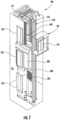
- FIG. 1 is a perspective view of an elevator system 101 including an elevator car 103, a counterweight 105, a roping 107, a guide rail 109, a machine 111, a position encoder 113, and a controller 115.
- the elevator car 103 and counterweight 105 are connected to each other by the roping 107.
- the roping 107 may include or be configured as, for example, ropes, steel cables, and/or coated-steel belts.
- the counterweight 105 is configured to balance a load of the elevator car 103 and is configured to facilitate movement of the elevator car 103 concurrently and in an opposite direction with respect to the counterweight 105 within an elevator shaft 117 and along the guide rail 109.
- the roping 107 engages the machine 111, which is part of an overhead structure of the elevator system 101.
- the machine 111 is configured to control movement between the elevator car 103 and the counterweight 105.
- the position encoder 113 may be mounted on an upper sheave of a speed-governor system 119 and may be configured to provide position signals related to a position of the elevator car 103 within the elevator shaft 117. In other embodiments, the position encoder 113 may be directly mounted to a moving component of the machine 111, or may be located in other positions and/or configurations as known in the art.
- the controller 115 is located, as shown, in a controller room 121 of the elevator shaft 117 and is configured to control the operation of the elevator system 101, and particularly the elevator car 103.
- the controller 115 may provide drive signals to the machine 111 to control the acceleration, deceleration, leveling, stopping, etc. of the elevator car 103.
- the controller 115 may also be configured to receive position signals from the position encoder 113.
- the elevator car 103 may stop at one or more landings 125 as controlled by the controller 115.
- the controller 115 can be located and/or configured in other locations or positions within the elevator system 101.
- the machine 111 may include a motor or similar driving mechanism.
- the machine 111 is configured to include an electrically driven motor.
- the power supply for the motor may be any power source, including a power grid, which, in combination with other components, is supplied to the motor.
- FIG. 1 is merely a non-limiting example presented for illustrative and explanatory purposes. It should be appreciated that any elevator system or system configuration may be employed.
- the building system 227 includes an elevator system 201 installed within a structure 229 (e.g., a building).
- the structure 229 may be an office building or a collection of office buildings that may or may not be physically located near each other.
- the structure 229 may include any number of floors that are accessible by the elevator system 201 and thus the structure 229 can include any number of landings (e.g., as shown in FIG. 1 ). Persons entering the structure 229 may enter at a lobby floor and may travel to a destination floor via one or more elevator cars 203 that are part of the elevator system 201.
- the elevator system 201 may include one or more computing devices, such as an elevator controller 215.
- the elevator controller 215 may be configured to control dispatching operations for one or more elevator cars 203 associated with the elevator system 201. It is understood that the elevator system 201 may utilize more than one elevator controller 215, and that each elevator controller may control a group of elevators cars 203. Although two elevator cars 203 are shown in FIG. 2 , those of skill in the art will appreciate that any number of elevators cars may be employed in the elevator and building systems that employ embodiments of the present disclosure.
- the elevator cars 203 can be located in the same hoistway or in different hoistways so as to allow coordination amongst elevator cars 201 in different elevator banks serving different floors (e.g., sky lobbies, etc.).
- the elevator system 201 may include various features as described above with reference to FIG. 1 and may also include other non-depicted elements and/or features as known in the art (e.g., drive, counterweight, safeties, etc.). Moreover, the elevators may be employed in any configuration with all elevators serving all floors of the building, some elevators only serving certain floors, a first group of elevator serving lower floors of a building and a sky lobby and a second group of elevators serving the sky lobby and upper floors of the building, etc.
- a user device 231 such as a mobile device (e.g., smart phone, smart watch, wearable technology, laptop, tablet, etc.).
- the user device 231 may include a mobile and/or personal device that is typically carried by a person, such as a phone, PDA, etc.
- the user device 231 may include a processor, memory, and communication module(s), as shown in FIG. 4A .
- the processor can be any type or combination of computer processors, such as a microprocessor, microcontroller, digital signal processor, application specific integrated circuit, programmable logic device, and/or field programmable gate array.
- the memory can be a non-transitory computer readable storage medium tangibly embodied in the user device 231 including executable instructions stored therein, for instance, as firmware.
- the communication module may implement one or more communication protocols as described in further detail herein, and may include features to enable wireless communication with external and/or remote devices separate from the user device 231.
- the user device 231 may further include a user interface (e.g., a display screen, a microphone, speakers, input elements such as a keyboard or touch screen, etc.) as known in the art.
- the elevator controller 215 may include a processor, memory, and a communication module as shown in FIG. 4B . Similar to the user device 231, the processor memory, and communication module may be implemented as described above, but as part of the elevator system 201.
- a user device and an elevator controller in accordance with embodiments of the present disclosure can communicate with one another, e.g., as shown in FIG. 3 .
- one or more user device 331 and the elevator controller 315 may communicate with one another when proximate to one another (e.g., within a threshold distance).
- the user device 331 and the elevator controller 315 may communicate over a network 333, that may be wired or wireless.
- Wireless communication networks can include, but are not limited to, Wi-Fi, short-range radio (e.g., Bluetooth ® ), near-field infrared, cellular network, etc.
- the elevator controller 315 may include, or be associated with (e.g., communicatively coupled to) one or more networked building elements 335, such as computers, kiosks, beacons, hall call fixtures, lanterns, bridges, routers, network nodes, etc.
- the networked element 335 may also communicate directly or indirectly with the user devices 331 using one or more communication protocols or standards (e.g., through the network 333).
- the networked element 335 may communicate with the user devices 331 using near-field communications (NFC) (e.g., network 333) and thus enable communication between the user devices 331 and the elevator controller 315.
- NFC near-field communications
- the elevator controller 315 may establish communication with one or more user devices 331 that are outside of the structure/building. Such connection may be established with various technologies including GPS, triangulation, or signal strength detection, by way of non-limiting example. Such technologies that allow communication can provide users and the system(s) described herein more time to perform the described functions.
- the user devices 331 communicate with the elevator controller 315 over multiple independent wired and/or wireless networks. Embodiments are intended to cover a wide variety of types of communication between the user devices 331 and the elevator controller 315, and embodiments are not limited to the examples provided in this disclosure.
- the network 333 may be any type of known communication network including, but not limited to, a wide area network (WAN), a local area network (LAN), a global network (e.g. Internet), a virtual private network (VPN), a cloud network, and an intranet.
- the network 333 may be implemented using a wireless network or any kind of physical network implementation known in the art.
- the user devices 331 and/or the networked devices 335 may be coupled to the elevator controller 315 through multiple networks 333 (e.g., cellular and Internet) so that not all user devices 331 and/or the networked devices 335 are coupled to the elevator controller 315 through the same network 333.
- One or more of the user devices 331 and the elevator controller 315 may be connected to the network 333 in a wireless fashion.
- the network 333 is the Internet and one or more of the user devices 331 execute a user interface application (e.g. a web browser) to contact the elevator controller 315 through the network 333.
- a request for elevator service may be communicated over one or more lines, connections, or networks, such as network 333, e.g., a request made by a user device 331 and transmitted through the network 333 to the elevator controller 315 to request elevator service.
- the request for service may be initiated by a mobile device controlled by and/or associated with a user, in a passive or active manner.
- the mobile device may be operative in conjunction with a Transmission Control Protocol (TCP) and/or a User Datagram Protocol (UDP).
- TCP Transmission Control Protocol
- UDP User Datagram Protocol
- a request for service may be authenticated or validated based on a location of the user device.
- a request for service may be fulfilled in accordance with one or more profiles, such as one or more user or mobile device profiles.
- the profiles may be registered as part of a registration process.
- an elevator system may be registered with a service provider.
- the elevator controller 315 may be associated with an elevator system (e.g., elevator systems 101, 201).
- the elevator controller 315 may be used to process or fulfill the requests for elevator service that are submitted from one or more user devices 331.
- the requests for elevator service may be received through the network 333 from the one or more user devices 331 and/or the networked building elements 335, which may be mobile devices, including, but not limited to phones, laptops, tablets, smartwatches, etc.
- One or more of the user devices 331 may be associated with (e.g., owned by) a particular user. The user may use his/her user device(s) 331 to request elevator service.
- a user of a user device 314 may request service in an affirmative or active manner.
- the user may enter a request for elevator service using an I/O interface of the user device 331, as described herein. That is, in some embodiments, an application, app, or other program may be installed and operated on the user device 331 wherein the user may interact with the app or program to request elevator service.
- the user may request elevator service in a passive manner.
- a profile may be established for the user or the particular user device 331, optionally as part of a registration process with, e.g., a service provider and/or through historical data tracking.
- the profile may contain a log of the user's history and/or activities, such as where the user has gone or traveled to, the user's preferences, or any other data that may be applicable to the user.
- the user profile may be accessed or analyzed to determine the likelihood or probability that the user will request elevator service at a particular moment in time (e.g., a particular day or time of day). Resources may be provisioned or allocated to fulfill the request (e.g., an elevator car call or reservation may be placed) in the event that the probability of requested service, or consumption, or use of an elevator is anticipated.
- the request for service may be conveyed or transmitted from the user device 331 through the network 333.
- the request for service may be transmitted to and/or over the Internet and/or a cellular network.
- the network(s) 333 may include infrastructure that may be organized to facilitate cloud computing.
- one or more servers such as a primary message server, a backup message server, and a device commissioning message server may be employed as part of the network 333.
- the request for service may specify a type of service requested, at any level of detail or abstraction. For example, a first request for service may specify that elevator service is requested, a second request for service may specify one or more of a departure floor and/or a destination floor, and a third request for service may specify that elevator service is desired to accommodate a heavy load (e.g., freight or cargo) with a number of other users or passengers in an amount less than a threshold.
- the request for service transmitted from the user device 331 may include an identifier associated with the user or the particular user device 331 in order to allow the elevator controller 315 to distinguish between users and/or user devices 331.
- FIGS. 4A-4B schematic block diagram illustrations of example computing systems 437a, 437b for a user device 431 and an elevator controller 415, respectively, are shown.
- the computing system 437a may be representative of computing elements or components of user devices, networked elements, mobile devices, etc. as employed in embodiments of the present disclosure.
- the computing system 437b may be representative of computing elements or components of controllers, elevator controller, networked elements, computers, etc.
- the computing system 437a can be configured as part of a user device 431, e.g., user device 231, 331 shown above.
- the computing system 437a can be configured to operate the user device 431, including, but not limited to, operating and controlling a touch-screen display to display various output and receive various input from a user's interaction with the touch-screen display.
- the computing system 437b can be configured as part of an elevator controller, e.g., elevator controller 115, 215, 315 shown above.
- the computing system 437b can be a computer or other type of controller that is physically connected or remote from mechanical control of the elevator system.
- the computing system 437b may be connected to various elements and components within a building that are associated with operation of an elevator system.
- the computing system 437a includes a memory 439a which may store executable instructions and/or data.
- the executable instructions may be stored or organized in any manner and at any level of abstraction, such as in connection with one or more applications, apps, programs, processes, routines, procedures, methods, etc.
- FIG. 4A As an example, at least a portion of the instructions are shown in FIG. 4A as being associated with a program 441a.
- the memory 439a can include RAM and/or ROM and can store the program 441a thereon, wherein the program 441a may be a mobile operating system and/or mobile applications to be used on the user device 431.
- the memory 439a may store data 443a.
- the data 443a may include profile or registration data (e.g., in a user device), a device identifier, or any other type(s) of data.
- the executable instructions stored in the memory 439a may be executed by one or more processors, such as a processor 445a, which may be a mobile processor in the user device 431.
- the processor 445a may be operative on the data 443a and/or configured to execute the program 441a.
- the executable instructions can be performed using a combination of the processor 445a and remote resources (e.g., data and/or programs stored in the cloud (e.g., remote servers)).
- the processor 445a may be coupled to one or more input/output (I/O) devices 447a.
- the I/O device(s) 447a may include one or more of a physical keyboard or keypad, a touchscreen or touch panel, a display screen, a microphone, a speaker, a mouse, a button, e.g., parts or features of a telephone or mobile device (e.g., a smartphone.
- the I/O device(s) 447a may be configured to provide an interface to allow a user to interact with the user device 431.
- the I/O device(s) 447a may support a graphical user interface (GUI) and/or voice-to-text capabilities for the user device 431.
- GUI graphical user interface
- the components of the computing system 437a may be operably and/or communicably connected by one or more buses.
- the computing system 437a may further include other features or components as known in the art.
- the computing system 437a may include one or more communication modules 449a, e.g., transceivers and/or devices configured to receive information or data from sources external to the computing system 437a.
- the communication modules 449a of the user device 431 can include a near-field communication chip (e.g., Bluetooth ® , Wi-Fi, etc.) and a cellular data chip, as known in the art.
- the computing system 437a may be configured to receive information over a network (wired or wireless), such as network 333 shown in FIG. 3 .
- the information received over the network may be stored in the memory 439a (e.g., as data 443a) and/or may be processed and/or employed by one or more programs or applications (e.g., program 441a).
- the computing systems 437a may be used to execute or perform embodiments and/or processes described herein, such as within and/or on user devices.
- the computing system 437a of the user device 431 enables a user interface to enable a user to make service requests to an elevator.
- the user device 431, and the computing system 437a thereof may communicate with the computing system 437b of the elevator controller 415.
- the elevator controller 415 includes a computing system 437b that is used to receive commands and/or instructions (e.g., data) from remote devices, including, but not limited to, the user device 431.
- the computing system 437b is configured to control operation of and/or reservation of elevator cars within one or more elevator hoistways.
- the computing system 437b (and program 439b stored thereon) may be configured to process requests for elevator service received from one or more user devices (e.g., user device 431). As part of the processing, the computing system 437b may validate or authenticate the user device 437 such that only certain user devices 431 may be able to communicate and/or make elevator service requests to the elevator controller 415.
- the computing system 437b of the elevator controller 415 includes components similar to that shown and described with respect to the computing system 437a of FIG. 4A .
- the elevator controller computing system 437b includes a memory 439b with at least one program 441b and data 443b stored thereon.
- the data 443b may include profile or registration data (e.g., related to user devices), elevator car data, elevator control data and/or programs, or any other type(s) of data associated with control and/or operation of an elevator system.
- a processor 445b may be configured to receive service requests through a communication module 449b from one or more user devices 431.
- the computing system 437b may further include one or more I/O devices 447b, including, but not limited to, control connections to one or more elevator mechanical controls and/or elevator cars. Further, in some configurations, the I/O devices 447b can include a monitor or display screen as part of a user interactive computing system that is associated with the elevator system and/or elevator controller 415.
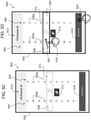
- FIGS. 5A-5D various illustrations of a user interface 500 implemented on a user device in accordance with an embodiment of the present disclosure are shown.
- a screen 502 of a user device may display the user interface 500 that represents a screen or interface of an application in accordance with an embodiment of the present disclosure.
- the user interface 500 can enable a user to make elevator service requests by operation and interaction with the user interface 500 displayed on the screen 502. That is, the user interface 500 can enable a user device to communicate with an elevator controller to make an elevator service request.
- the user interface 500 as shown in the embodiments illustrated in FIGS.
- the scrollable lists 504, 506 are configured to each include a plurality of list elements 504a, 506a, respectively.
- the list elements 504a, 506a can be a listing of landing floors within a building. That is, the scrollable lists 504, 506 are configured to display a list of options that a user can select from to make an elevator service request to thus travel within a building based on the elevator service request that incorporates information and/or data from the scrollable lists 504, 506.
- a first scrollable list 504 can provide options (e.g., list elements 504a) to define a "From" or starting floor or landing of a building to be traveled from.
- a second scrollable list 506 is displayed next to the first scrollable list and provides a list of options (e.g., list elements 506a) for a "To" or destination floor or landing.
- the contents or options of the first and second scrollable lists 504, 506 are the same and can be based on the accessible floors of an elevator system.
- the first and second scrollable lists are displayed in a single interactive image or user interface.
- each scrollable list 504, 506 has an associated selection box 508, 510 that is labeled "From" and "To.” Although shown with specific shapes and words or indictors, those of skill in the art will appreciate that the selection boxes 508, 510 can have various geometries, color, indicators, words, icons, etc. without departing from the scope of the present disclosure. Further, each selection box 508, 510 and/or scrollable list 504, 504 can support all floor labels (e.g., alpha and/or numeric). In some embodiments, the scrollable lists 504, 506 can support front and rear door selection, indicate sky lobby floors (e.g., transfers between elevator shafts), or other aspects and/or features of the elevator system or elevator cars therein.
- sky lobby floors e.g., transfers between elevator shafts
- the user interface 500 includes additional features, which may be optional.
- an information region 512 can be located within the user interface 500.
- the information region 512 provides information regarding the current building (e.g., an address) for which the user is using the interface 500 to communicate and/or control the elevator system.
- information region 512 can be static and/or defined by various information obtained by a user device (such as GPS, Wi-Fi location, etc.).
- the information region 512 can be an interactive tab or other interactive feature that can enable a user to make selections, change displayed information, change the building selection to another building, etc.
- the information region 512 can be located at any position on the user interface 500 and/or can take various geometric forms, colors, etc.
- the user interface 500 is also shown having a swap icon 514.
- the swap icon 514 enables a user to swap the currently selected floors on the two scrollable lists 504, 506. For example, when a user selects to travel from a lobby to a fifth floor, they may wish to travel back to the lobby from the fifth floor, and the swap icon 514 enables easy change of the selected floors on each scrollable list 504, 506.
- the user interface (or memory associated therewith) stores or remembers the user's last selected trip and defaults to labeling those floors in the selection boxes 508, 510 (e.g., To/From). In one embodiment, the system may assume the user wishes to reverse their previous trip and will swap the numbers in the selection boxes 508, 510 (e.g., To/From).
- the system may assume that if the user entered the building at the lobby and went to the 5th floor, that the user's next trip would be from the 5th floor to the lobby and preset such a trip in the selection boxes 508, 510 (e.g., To/From). Other preset pairings may be provided by the system and displayed on the user interface 500.
- the system may: recognize that the user typically travels from the lobby to the 10th floor in the morning when reporting for work and preset the selection boxes 508, 510 (e.g., To/From) for such a trip; recognize that the user typically travels to the cafeteria on the 2nd floor around noon and preset the selection boxes 508, 510 (e.g., To/From) for such a trip at an appropriate time; the system may then preset the selection boxes 508, 510 (e.g., To/From) for a return trip from the 2nd floor (cafeteria) to the 10th floor after the user travels to the cafeteria; and finally the system may recognize that the user leaves the building in the evening and preset the selection boxes 508, 510 (e.g., To/From) for a trip from the 10th floor to the lobby.
- the system and user interface 500 may sync with a user's electronic calendar or other scheduling device to preset the selection boxes 508, 510 (e.g., To/From) for a trip from the
- the user interface 500 includes a "Call Elevator" icon 516 that is used to make an elevator service request of an elevator system based on the selected floors of the scrollable lists 504, 506 and indicated within the respective selection boxes 508, 510.
- the call elevator icon 516 When the call elevator icon 516 is selected or actuated by a user, the user device will transmit a request to an associated elevator system, and an elevator car may be dispatched based on the service request.
- FIGS. 5A-5D the schematic illustrations provide a demonstration of use of the user interface 500.
- a user 518 can scroll the second scrollable list 506 to position an alpha-numeric indicator within the second selection box 510.
- the second scrollable list 506 is, as shown, a digital scroll wheel that can be "spun" to change an element of the second scrollable list 506 that is located within the second selection box 510.
- the second scrollable list 506 is shown adjusted such that floor "5" is located within the second selection box 510.
- the user 518 can scroll the first scrollable list 504 to position an alpha-numeric indicator within the first selection box 508.
- the first scrollable list 504 is, as shown, a digital scroll wheel that can be "spun” to change an element of the first scrollable list 504 that is located within the first selection box 508
- the first scrollable list 504 is shown adjusted such that floor "13" is located within the first selection box 508.
- FIG. 5D illustrates possible actions the user 518 can take to make an elevator service request based on the selected information in the scrollable lists 504, 506 and selected in the selection boxes 508, 510.
- the user 518 can perform a swiping action 520 across the first and second selection boxes 508, 510 to prompt the program of the user interface 500 to generate and send an elevator service request to an elevator controller. That is, an interactive call region 522 is defined about the first and second selection boxes 508, 510, and the user 518 can interact with the user interface 500 to make an elevator service request.
- Another option is for the user to press 524 a request button, e.g., call elevator icon 516.
- the call elevator icon 516 may be a swipable icon, rather than a press-based icon.
- Embodiments provided herein enable a scrolling mechanic on a user device to provide easier selection for input of desired elevator travel within a building.
- the number of list elements within a particular scrollable list can be a set number of floors or can be changed dynamically based on a particularly building configuration. For example, when a user with a user device having a program or application as described herein enters a building, the user device can obtain floor information regarding an elevator system (either directly or indirectly). From this information, the application can populate the scrollable lists with list elements that represent the floors that are accessing within the building by elevator.
- the scrollable lists can be configured to display alternate floor names and/or locations that map to represented floors (e.g., additional or alternative information or names based on the floors of the building).
- the two scrollable lists can have various scrolling mechanisms, and are not limited to the vertical scrolling shown in FIGS. 5A-5D .
- horizontal or other directional scrolling can be employed without departing from the scope of the present disclosure.
- the scrollable lists may only display floors that the user is permitted to access.
- the scrollable lists could display all floors but grey-out floors or otherwise distinguish that the user is not permitted to access one or more specific floors shown on the scrollable list(s).
- the interactive call region 522 e.g., a selection area on the screen, defines the floor selection for both origin ("from") and destination ("to") within the selection boxes 508, 510. Because of the interactive call region 522, user precision may be reduced or relaxed, and thus a user is not required to be exactly precise with rotation of the scrollable lists 504, 506. That is, each list element 504a, 506a need only to be approximately positioned within the respective selection box 508, 510 by the user 518.
- the user interface 500 may include a "snap-in/elastic" mechanic to assist scrolling to specific list elements 504a, 506a within a tolerance when the user 518 is “drag-scrolling.” Further, in some embodiments, the user interface 500 may also include speed scrolling to reach extreme ends of each scrollable list 504, 560 using a "flick" gesture.”
- the design of the selection boxes 508, 510 can increase user comprehension regarding selection of origin and destination floors when making an elevator service request.
- the selection boxes 508, 510 have an arrow design of From/To selection areas which may increase comprehension of Origin-to-Destination for the user.
- the orientation of the arrow shape (or any shape of the selection boxes 508, 510) could change dynamically to reflect the actual direction of the trip, e.g., traveling up or down.
- the swap icon 514 allows one-touch interaction with the user interface 500 to enable selection of a return trip that is based on a previous trip.
- the scrollable lists 504, 506 may be static between uses, such that the most recent/previous trip may be displayed to a user when the user interface 500 is first opened or displayed.
- the displayed and selected list elements 504a, 506a can be displayed based on various different program configurations.
- the user interface 500 may reset to default floors (e.g., first floor for both the first and second scrollable lists 504, 506) each time the program is opened, the program can remember or store a previous floor pair, or may automatically swap selections for a return trip.
- additional scrollable lists may be provided on the user interface 500.
- an additional scrollable list may be provided to enable a user to input a departure time (e.g., a request made in advance). Further, in some embodiments, an additional scrollable list may be provided to enable selection of a number of passengers to be traveling on the currently made request.
- a user device if a user device is held in portrait mode, two scrollable lists may be displayed, and if the user rotates the user device to a landscape mode, additional scrollable lists may populate the screen.
- a user may be able to toggle various types of scrollable lists to be displayed on the user interface 500.
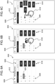
- FIGS. 6A-6C alternative features of a user interface in accordance with an embodiment of the present disclosure are shown.
- FIG. 6A-6C illustrate different display features of a user interface 600 than that shown in FIGS. 5A-5D (user interface 500), but may be part of the same program or application, or may be entirely independent thereof.
- the user interface 600 may be an interactive user interface that is part of a program or application that can be used to make elevator service requests, as described above. That is, the user interface 600 can be used for calling an elevator remotely.
- retained floor pairs 626 may be stored in the application or program (or memory associated therewith). Embodiments provided herein enable simple ways to interact with the retained floor pairs 626, to gain more information related to one or more of the floors, to remove retained floor pairs 626, to rename the retained floor pairs 626, place an elevator service request to travel between the retained floor pairs 626, etc.
- the retained floor pairs 626 may be set, established, or stored based on use of the features of the user interface 500 shown and described above with respect to FIGS. 5A-5D .
- the retained floor pairs 626 can be predefined, based on historical data of a particular user, based on popular origin-destination pairs of the particular building (e.g., cafeteria, gym, particular tenant, etc.), etc.
- the retained floor pairs 626 indicate an origin floor/landing on the left in FIG. 6A , a destination floor/landing on the right thereof, and a direction indicator between the origin and destination floor/landing.
- Each of the retained floor pairs 626 can include alphanumeric characters, as illustrated. Further, as shown, any of the elements of the retained floor pairs 626 can include additional information, icons, etc. For example, as shown, if a letter or other icon or indicator is used to designate an origination or destination floor, an information icon 628 can be displayed over the icon or indicator, to thus provide information to a user regarding the indicated floor. Further, such information icon can be displayed over a numbered floor and can provide information about the floor (e.g., if a cafeteria is located on the particular floor).
- each retained floor pair 626 is a call elevator icon 616, similar to that described above with reference to FIGS. 5A-5D .
- the call elevator icon 616 can be pressed by a user to make an elevator service request based on the particular retained floor pair 626.
- a user 618 may press and hold on a retained floor pair 626, a display element thereof, and/or an information icon 628 to reveal more information about a particular or specific floor. Additionally, as illustrated in FIG. 6C , a user 618 may swipe (e.g., to the left) on the retained floor pair 626 to enable removal of the particular retained floor pair 626 from the list of retained floor pairs.
- the user 618 may swipe to the right on a particular retained floor pair 626 to signal an intent to repeat that trip.
- the position of the call elevator icon 616 in association with a respective retained floor pair 626 may be modified by program or app configurations (e.g., locality).
- users may assign custom labels (e.g., "home,” “gym,” “cafeteria,” “work,” “HR,” “dentist,” etc.) to each retained floor pair 626.
- the user may interact with the custom label as indicated by the gestures described above.
- the alphanumeric information of the retained floor pair 626 may be revealed (e.g., display of floor numbers).
- the user interface 600 further includes an information region 612, similar to that described above.
- the information region 612 includes a dropdown menu to enable a user to select different addresses/buildings.
- the information region 612 can include various interactive elements 628.
- the interactive elements 628 include a "Recents" tab and a "New Trip” tab.
- a user can click on the "Recents” tab to display the user interface 600 shown in FIGS. 6A-6C .
- the "Recents" tab may provide a recents list or list of elevator trips that have recently or historically been taken by a user of the user device. That is, a recents list may be displayed to a user such that the user can view recent or historical elevator trips.
- the recents list can include one or more retained floor pairs 626, as shown in FIGS. 6A-6C .
- the "New Trip" tab may bring up key pad to enable a user to input an origin and destination floor that is different from the user interface 500 of FIGS. 5A-5D (e.g., a numerical keypad).
- the recents list (i.e., the list of retained floor pairs) can be automatically sorted in chronological order, such that the most recent trip appears at the top of the list for easy access by a user. Further, the recents list can be automatically sorted by chronological order, may be sorted based on a time of day (e.g., based on historical data of the user), or may be sorted based on any other criteria.
- the position of the call elevator icon 616 can be modified per user configuration and/or localization. Further, in some embodiments, a "seamless" mode may be used to prompt or provide a most recent retained floor pair 626 could be automatically displayed or toggled for ease of use.
- an elevator service request can be made by a swipe right gesture on a particular retained floor pair 626. Further, a particular retained floor pair 626 can be removed from the list with a swipe left gesture (or an option for "Remove” can be provided, as shown in FIG. 6C ). As noted, a user can force-press/press-and-hold on a retained floor pair 626 or portion thereof to get more information or full name related to the retained floor pair 626 or part thereof. Further, as noted, a user can assign custom name(s)/phrase(s) for specific retained floor pairs 626 (which can be associated with an address, building, etc.).
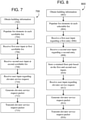
- a non-claimed flow process 700 may be used in connection with one or more entities, devices, or systems, such as those described herein.
- the flow process 700 may be used to receive user input requests and generate a request for elevator service and then transmit such request over one or more networks to thus make a remote request for elevator service.
- the flow process 700 may be a program or application functional process that can be performed using one or more processors, memory, input/output devices, etc. such as those shown and described above. In some embodiments, the flow process 700 can be performed on a user device as described above.
- the user device obtains building information over one or more networks (e.g., Wi-Fi, Bluetooth ® , geolocation, RFID, local network, etc.).
- the building information can include information regarding one or more elevator systems located within the building.
- Such elevator system information can include all available floors to which elevator cars travel and/or information regarding the one or more floors (e.g., tenants, features of the floors, etc.).
- list elements are populated or set for each scrollable list of the application/program. That is, for example, the scrollable lists shown and described with respect to FIGS. 5A-5D can be populated with information related to the particular building in the user/user device are located. For example, two scrollable lists of a user interface can each be populated with all floor numbers or alphanumeric indicators (or other information) with each floor number or other indicator being a list element as shown and described above.
- a first user input request at one of the two scrollable lists is received. That is, for example, a user can scroll or otherwise manipulate a first scrollable wheel to adjust a list element that is displayed within a selection box of the user interface.
- a second user input request at the other of the two scrollable lists is received. That is, for example, a user can scroll or otherwise manipulate a second scrollable wheel to adjust a list element that is displayed within a selection box of the user interface.
- a user input request regarding an elevator service request is received. For example, after adjusting the two scrollable wheels (at blocks 706, 708), the user may swipe in an interactive call region of the user interface. Such swiping on the user interface can indicate a user's desire to request elevator service to travel between the elevator floors selected or indicated based on the input received at block 706, 708.
- an elevator service request packet can be generated within the user device.
- the elevator service request packet can be an electronic communication packet that is configured to be transmitted over one or more different types of communication networks and can be configured to be read by an elevator controller or a computer system/program associated with an elevator controller.
- the generated elevator service request packet can be transmitted to an elevator controller or network of the building to which the elevator controller is connected. Accordingly, an elevator service request can be generated and requested remotely by operation of a user device employing flow process 700.
- a memory can be configured to store and retain information related to the elevator service request that is generated (see, e.g., FIG. 8 ).
- information may include data related to the particular building, the time the elevator service request is made, where in the building or outside of the building the request is made from, if the request is similar or the same as prior requests in the same building, etc
- Flow process 800 may incorporate additional or alternative steps without departing from the scope of the present disclosure.
- the flow process 800 may be performed by a processor on a user device (e.g., as described above) with various related applications and/or data stored in a memory of the user device.
- the user device obtains building information over one or more networks (e.g., Wi-Fi, Bluetooth ® , geolocation, RFID, local network, etc.).
- the building information can include information regarding one or more elevator systems located within the building.
- Such elevator system information can include all available floors to which elevator cars travel and/or information regarding the one or more floors (e.g., tenants, features of the floors, etc.).
- list elements are populated in one or more lists of the application/program on the user device. That is, for example, the scrollable lists shown and described with respect to FIGS. 5A-5D can be populated with information related to the particular building in the user/user device are located.
- the floor information can be retained digitally on the memory, and a user can interact with a floor selection key pad that can reference or be associated with the retained floor information.
- a user may use voice input to interact with and prompt the system to reference and select from the floor information
- a first user input request is received regarding a first entry (e.g., selection of a "from" or origination floor).
- a first entry e.g., selection of a "from" or origination floor.
- a user can scroll or otherwise manipulate a first scrollable wheel to adjust a list element that is displayed within a selection box of the user interface.
- a user can provide the first user input request through selection or input on an alpha-numeric keypad (e.g., physical or digital) and/or voice input.
- a second user input request is received regarding a second entry (e.g., selection of a "to" or destination floor).
- a second entry e.g., selection of a "to" or destination floor.
- a user can scroll or otherwise manipulate a second scrollable wheel to adjust a list element that is displayed within a selection box of the user interface.
- a user can provide the second user input request through selection or input on an alpha-numeric keypad (e.g., physical or digital) and/or voice input.
- the first and second user input requests/entries are stored on a memory and are used to generate a retained floor pair, e.g., as described with respect to FIGS. 6A-6C .
- the flow process 800 can be repeated multiple times to form a retained floor pair list (e.g., multiple different retained floor pairs) or a recents list (which can be automatically populated).
- a user input request regarding an elevator service request is received with respect to one of the retained floor pairs. For example, after generating and storing one or more retained floor pairs, the user may swipe across one of the retained floor pairs of the user interface (e.g., on the retained floor pair list). Such swiping on the user interface can indicate a user's desire to request elevator service to travel between the elevator floors of the retained floor pair. In another embodiment, swiping may prompt a call elevator icon or button to appear, which can then be selected by the user. In other embodiments, a call elevator button may be displayed with and adjacent to the retained floor pair(s) (e.g., as shown in FIGS. 6A-6C ), and a user may select the call elevator button to make an elevator service request.
- an elevator service request packet can be generated within the user device in response to the user input request received at block 812.
- the elevator service request packet can be an electronic communication packet that is configured to be transmitted over one or more different types of communication networks and can be configured to be read by an elevator controller or a computer system/program associated with an elevator controller.
- the generated elevator service request packet can be transmitted to an elevator controller or network of the building to which the elevator controller is connected. Accordingly, an elevator service request can be generated and requested remotely by operation of a user device employing flow process 800.
- aspects of the disclosure may be used in connection with one or more data mining applications. For example, patterns of elevator usage may be analyzed to suggest alternative times that users could consume elevator resources. Advertising opportunities may be available. For example, if a user profile indicates that the user likes to drink coffee, coupons for free coffee may be provided to the user as an incentive to utilize the elevator during off-peak times or periods.
- various functions or acts may take place at a given location and/or in connection with the operation of one or more apparatuses, systems, or devices. For example, in some embodiments, a portion of a given function or act may be performed at a first device or location (e.g., user device), and the remainder of the function or act may be performed at one or more additional devices or locations (e.g., elevator controller). Further, embodiments described herein may be implemented using one or more technologies.
- an apparatus or system may include one or more processors and memory storing instructions that, when executed by the one or more processors, cause the apparatus or system to perform one or more methodological acts as described herein.
- Various mechanical components known to those of skill in the art may be employed without departing from the scope of the present disclosure.
- Embodiments may be implemented as one or more apparatuses, systems, and/or methods.
- instructions may be stored on one or more computer program products or computer-readable media, such as a transitory and/or non-transitory computer-readable medium.
- the instructions when executed, may cause an entity (e.g., an apparatus or system) to perform one or more methodological acts as described herein.
Description
- The subject matter disclosed herein generally relates to elevator service requests for elevators and, more particularly, to elevator service requests using user devices.
- Elevator systems can receive input from users through mechanical, electrical, and/or electromechanical device located within or as part of the elevator system. That is, requests for elevator service are typically made by potential passengers when the passenger is already located at an elevator landing. However, having remote mechanism to make such requests may be advantageous. For example, the use of personal user devices can enable remote elevator service requests, thus improving user experience and/or enabling improved elevator management within a building. Further improvements thereon may be desirable.
-
EP 2730530 A1 discloses a method for giving a destination call to the control system of an elevator system in which one or more predetermined departure floor-destination floor pairs are presented on a display of a device. - According to one embodiment, a method for making elevator service requests is provided as defined by claim 1.
- In some embodiments of the method the elevator service request packet includes information including the origination floor and the destination floor.
- In some embodiments of the method the computing device is a smartphone.
- Some embodiments of the method include displaying a call elevator icon on the user interface in the recents list, the call elevator icon associated with the user input regarding an elevator service request and the user input received on the recents list is at the call elevator icon.
- Some embodiments of the method include receiving a swipe input on the recents list, displaying a remove icon proximate the user input regarding an elevator service request, receiving input at the remove icon, and deleting the user input regarding an elevator service request based on the input received at the remove icon.
- Some embodiments of the method include receiving a swipe input on the recents list, wherein generating the elevator service request packet is based on the swipe input.
- Some embodiment of the method include receiving input to generate a new trip and displaying a first scrollable wheel and a second scrollable wheel, wherein each scrollable wheel includes a plurality of list elements associated with floors within a building.
- Some embodiments of the method include storing data related to a most recent elevator trip in a memory and displaying a retained floor pair associated with the most recent elevator trip on the display at a top of the recents list.
- Some embodiments of the method include storing data related to a plurality of elevator trips in a memory, wherein the data comprises at least one of a time of day and a location of a user and displaying a retained floor pair associated with the data on the display at a top of the recents list.
- According to another embodiment, a user device for making elevator service requests is provided as defined by
claim 10. - In some embodiments of the user device the elevator service request packet includes information including the origination floor and the destination floor.
- In some embodiments of the user device the computing device is a smartphone.
- In some embodiments of the user device the instructions further include instructions to display a call elevator icon on the user interface in the recents list, the call elevator icon associated with the user input regarding an elevator service request and wherein the user input received on the recents list is at the call elevator icon.
- In some embodiments of the user device the instructions further include instructions to receive a swipe input on the recents list, display a remove icon proximate the user input regarding an elevator service request, receive input at the remove icon, and delete the user input regarding an elevator service request based on the input received at the remove icon.
- In some embodiments of the user device the instructions further include instructions to receive a swipe input on the recents list, wherein generating the elevator service request packet is based on the swipe input.
- In some embodiments of the user device the instructions further include instructions to receive input to generate a new trip and display a first scrollable wheel and a second scrollable wheel, wherein each scrollable wheel includes a plurality of list elements associated with floors within a building.
- In some embodiments of the user device the instructions further include instructions to store data related to a most recent elevator trip in a memory and display a retained floor pair associated with the most recent elevator trip on the display at a top of the recents list.
- In some embodiments of the user device the instructions further include instructions to store data related to a plurality of elevator trips in a memory, wherein the data comprises at least one of a time of day and a location of a user and display a retained floor pair associated with the data on the display at a top of the recents list.
- Technical effects of embodiments of the present disclosure include user devices and methods of operation configured to provide user interfaces and receive inputs thereon to generate elevator service requests.
- It should be understood that the following description and drawings are intended to be illustrative and explanatory in nature and non-limiting.
- The present disclosure is illustrated by way of example and not limited in the accompanying figures in which like reference numerals indicate similar elements
-
FIG. 1 is a schematic illustration of an exemplary elevator system that may employ various embodiments of the present disclosure; -
FIG. 2 is a schematic block diagram illustrating a system that may be configured in accordance with one or more embodiments of the present disclosure; -
FIG. 3 is a schematic illustration of a system in accordance with an embodiment of the present disclosure; -
FIG. 4A is a schematic illustration of a computing system of a user device in accordance with an embodiment of the present disclosure; -
FIG. 4B is a schematic illustration of a computing system of an elevator controller in accordance with an embodiment of the present disclosure; -
FIG. 5A is a schematic illustration of a user interface on a user device in accordance with an embodiment of the present disclosure; -
FIG. 5B is another schematic illustration of the user interface ofFIG. 5A ; -
FIG. 5C is another schematic illustration of the user interface ofFIG. 5A ; -
FIG. 5D is another schematic illustration of the user interface ofFIG. 5A ; -
FIG. 6A is a schematic illustration of a user interface on a user device in accordance with another embodiment of the present disclosure; -
FIG. 6B is another schematic illustration of the user interface ofFIG. 6A ; -
FIG. 6C is another schematic illustration of the user interface ofFIG. 6A ; -
FIG. 7 illustrates a non-claimed flow process for interacting with an elevator system in accordance with an embodiment of the present disclosure; and -
FIG. 8 illustrates a non-claimed flow process for interacting with an elevator system in accordance with another embodiment of the present disclosure. - As shown and described herein, various features of the disclosure will be presented. Various embodiments may have the same or similar features and thus the same or similar features may be labeled with the same reference numeral, but preceded by a different first number indicating the figure to which the feature is shown. Thus, for example, element "a" that is shown in FIG. X may be labeled "Xa" and a similar feature in FIG. Z may be labeled "Za." Although similar reference numbers may be used in a generic sense, various embodiments will be described and various features may include changes, alterations, modifications, etc. as will be appreciated by those of skill in the art, whether explicitly described or otherwise would be appreciated by those of skill in the art.
-
FIG. 1 is a perspective view of anelevator system 101 including anelevator car 103, acounterweight 105, aroping 107, aguide rail 109, a machine 111, aposition encoder 113, and acontroller 115. Theelevator car 103 andcounterweight 105 are connected to each other by theroping 107. Theroping 107 may include or be configured as, for example, ropes, steel cables, and/or coated-steel belts. Thecounterweight 105 is configured to balance a load of theelevator car 103 and is configured to facilitate movement of theelevator car 103 concurrently and in an opposite direction with respect to thecounterweight 105 within anelevator shaft 117 and along theguide rail 109. - The
roping 107 engages the machine 111, which is part of an overhead structure of theelevator system 101. The machine 111 is configured to control movement between theelevator car 103 and thecounterweight 105. The position encoder 113 may be mounted on an upper sheave of a speed-governor system 119 and may be configured to provide position signals related to a position of theelevator car 103 within theelevator shaft 117. In other embodiments, theposition encoder 113 may be directly mounted to a moving component of the machine 111, or may be located in other positions and/or configurations as known in the art. - The
controller 115 is located, as shown, in acontroller room 121 of theelevator shaft 117 and is configured to control the operation of theelevator system 101, and particularly theelevator car 103. For example, thecontroller 115 may provide drive signals to the machine 111 to control the acceleration, deceleration, leveling, stopping, etc. of theelevator car 103. Thecontroller 115 may also be configured to receive position signals from theposition encoder 113. When moving up or down within theelevator shaft 117 alongguide rail 109, theelevator car 103 may stop at one ormore landings 125 as controlled by thecontroller 115. Although shown in acontroller room 121, those of skill in the art will appreciate that thecontroller 115 can be located and/or configured in other locations or positions within theelevator system 101. - The machine 111 may include a motor or similar driving mechanism. In accordance with embodiments of the disclosure, the machine 111 is configured to include an electrically driven motor. The power supply for the motor may be any power source, including a power grid, which, in combination with other components, is supplied to the motor.
- Although shown and described with a roping system, elevator systems that employ other methods and mechanisms of moving an elevator car within an elevator shaft, including ropeless elevator systems and/or elevator systems with more than one elevator car in each elevator shaft, may employ embodiments of the present disclosure.
FIG. 1 is merely a non-limiting example presented for illustrative and explanatory purposes. It should be appreciated that any elevator system or system configuration may be employed. - Turning now to
FIG. 2 , a schematic illustration of abuilding system 227 in an example embodiment of the present disclosure is shown. Thebuilding system 227 includes anelevator system 201 installed within a structure 229 (e.g., a building). In some embodiments, thestructure 229 may be an office building or a collection of office buildings that may or may not be physically located near each other. Thestructure 229 may include any number of floors that are accessible by theelevator system 201 and thus thestructure 229 can include any number of landings (e.g., as shown inFIG. 1 ). Persons entering thestructure 229 may enter at a lobby floor and may travel to a destination floor via one ormore elevator cars 203 that are part of theelevator system 201. - The
elevator system 201 may include one or more computing devices, such as anelevator controller 215. Theelevator controller 215 may be configured to control dispatching operations for one ormore elevator cars 203 associated with theelevator system 201. It is understood that theelevator system 201 may utilize more than oneelevator controller 215, and that each elevator controller may control a group ofelevators cars 203. Although twoelevator cars 203 are shown inFIG. 2 , those of skill in the art will appreciate that any number of elevators cars may be employed in the elevator and building systems that employ embodiments of the present disclosure. Theelevator cars 203 can be located in the same hoistway or in different hoistways so as to allow coordination amongstelevator cars 201 in different elevator banks serving different floors (e.g., sky lobbies, etc.). It is understood that theelevator system 201 may include various features as described above with reference toFIG. 1 and may also include other non-depicted elements and/or features as known in the art (e.g., drive, counterweight, safeties, etc.). Moreover, the elevators may be employed in any configuration with all elevators serving all floors of the building, some elevators only serving certain floors, a first group of elevator serving lower floors of a building and a sky lobby and a second group of elevators serving the sky lobby and upper floors of the building, etc. - Also shown in
FIG. 2 is auser device 231, such as a mobile device (e.g., smart phone, smart watch, wearable technology, laptop, tablet, etc.). Theuser device 231 may include a mobile and/or personal device that is typically carried by a person, such as a phone, PDA, etc. Theuser device 231 may include a processor, memory, and communication module(s), as shown inFIG. 4A . As described below, the processor can be any type or combination of computer processors, such as a microprocessor, microcontroller, digital signal processor, application specific integrated circuit, programmable logic device, and/or field programmable gate array. The memory can be a non-transitory computer readable storage medium tangibly embodied in theuser device 231 including executable instructions stored therein, for instance, as firmware. The communication module may implement one or more communication protocols as described in further detail herein, and may include features to enable wireless communication with external and/or remote devices separate from theuser device 231. Theuser device 231 may further include a user interface (e.g., a display screen, a microphone, speakers, input elements such as a keyboard or touch screen, etc.) as known in the art. - The
elevator controller 215 may include a processor, memory, and a communication module as shown inFIG. 4B . Similar to theuser device 231, the processor memory, and communication module may be implemented as described above, but as part of theelevator system 201. - A user device and an elevator controller in accordance with embodiments of the present disclosure can communicate with one another, e.g., as shown in
FIG. 3 . For example, one ormore user device 331 and theelevator controller 315 may communicate with one another when proximate to one another (e.g., within a threshold distance). Theuser device 331 and theelevator controller 315 may communicate over anetwork 333, that may be wired or wireless. Wireless communication networks can include, but are not limited to, Wi-Fi, short-range radio (e.g., Bluetooth®), near-field infrared, cellular network, etc. In some embodiments, theelevator controller 315 may include, or be associated with (e.g., communicatively coupled to) one or morenetworked building elements 335, such as computers, kiosks, beacons, hall call fixtures, lanterns, bridges, routers, network nodes, etc. Thenetworked element 335 may also communicate directly or indirectly with theuser devices 331 using one or more communication protocols or standards (e.g., through the network 333). - For example, the
networked element 335 may communicate with theuser devices 331 using near-field communications (NFC) (e.g., network 333) and thus enable communication between theuser devices 331 and theelevator controller 315. In some embodiments, theelevator controller 315 may establish communication with one ormore user devices 331 that are outside of the structure/building. Such connection may be established with various technologies including GPS, triangulation, or signal strength detection, by way of non-limiting example. Such technologies that allow communication can provide users and the system(s) described herein more time to perform the described functions. In example embodiments, theuser devices 331 communicate with theelevator controller 315 over multiple independent wired and/or wireless networks. Embodiments are intended to cover a wide variety of types of communication between theuser devices 331 and theelevator controller 315, and embodiments are not limited to the examples provided in this disclosure. - The
network 333 may be any type of known communication network including, but not limited to, a wide area network (WAN), a local area network (LAN), a global network (e.g. Internet), a virtual private network (VPN), a cloud network, and an intranet. Thenetwork 333 may be implemented using a wireless network or any kind of physical network implementation known in the art. Theuser devices 331 and/or thenetworked devices 335 may be coupled to theelevator controller 315 through multiple networks 333 (e.g., cellular and Internet) so that not alluser devices 331 and/or thenetworked devices 335 are coupled to theelevator controller 315 through thesame network 333. One or more of theuser devices 331 and theelevator controller 315 may be connected to thenetwork 333 in a wireless fashion. In one non-limiting embodiment, thenetwork 333 is the Internet and one or more of theuser devices 331 execute a user interface application (e.g. a web browser) to contact theelevator controller 315 through thenetwork 333. - Embodiments provided herein are direct to apparatuses, systems, and methods for making and fulfilling requests for elevator service. In some embodiments, a request for elevator service may be communicated over one or more lines, connections, or networks, such as
network 333, e.g., a request made by auser device 331 and transmitted through thenetwork 333 to theelevator controller 315 to request elevator service. The request for service may be initiated by a mobile device controlled by and/or associated with a user, in a passive or active manner. In some embodiments, the mobile device may be operative in conjunction with a Transmission Control Protocol (TCP) and/or a User Datagram Protocol (UDP). In some embodiments, a request for service may be authenticated or validated based on a location of the user device. In some embodiments, a request for service may be fulfilled in accordance with one or more profiles, such as one or more user or mobile device profiles. In some embodiments the profiles may be registered as part of a registration process. In some embodiments, an elevator system may be registered with a service provider. - As noted, the
elevator controller 315 may be associated with an elevator system (e.g.,elevator systems 101, 201). Theelevator controller 315 may be used to process or fulfill the requests for elevator service that are submitted from one ormore user devices 331. The requests for elevator service may be received through thenetwork 333 from the one ormore user devices 331 and/or thenetworked building elements 335, which may be mobile devices, including, but not limited to phones, laptops, tablets, smartwatches, etc. One or more of theuser devices 331 may be associated with (e.g., owned by) a particular user. The user may use his/her user device(s) 331 to request elevator service. - For example, a user of a user device 314 may request service in an affirmative or active manner. The user may enter a request for elevator service using an I/O interface of the
user device 331, as described herein. That is, in some embodiments, an application, app, or other program may be installed and operated on theuser device 331 wherein the user may interact with the app or program to request elevator service. - In other embodiments, or in combination therewith, the user may request elevator service in a passive manner. For example, a profile may be established for the user or the
particular user device 331, optionally as part of a registration process with, e.g., a service provider and/or through historical data tracking. The profile may contain a log of the user's history and/or activities, such as where the user has gone or traveled to, the user's preferences, or any other data that may be applicable to the user. In some embodiments, the user profile may be accessed or analyzed to determine the likelihood or probability that the user will request elevator service at a particular moment in time (e.g., a particular day or time of day). Resources may be provisioned or allocated to fulfill the request (e.g., an elevator car call or reservation may be placed) in the event that the probability of requested service, or consumption, or use of an elevator is anticipated. - The request for service may be conveyed or transmitted from the
user device 331 through thenetwork 333. For example, the request for service may be transmitted to and/or over the Internet and/or a cellular network. The network(s) 333 may include infrastructure that may be organized to facilitate cloud computing. For example, one or more servers, such as a primary message server, a backup message server, and a device commissioning message server may be employed as part of thenetwork 333. - In some embodiments, the request for service may specify a type of service requested, at any level of detail or abstraction. For example, a first request for service may specify that elevator service is requested, a second request for service may specify one or more of a departure floor and/or a destination floor, and a third request for service may specify that elevator service is desired to accommodate a heavy load (e.g., freight or cargo) with a number of other users or passengers in an amount less than a threshold. In some embodiments, the request for service transmitted from the
user device 331 may include an identifier associated with the user or theparticular user device 331 in order to allow theelevator controller 315 to distinguish between users and/oruser devices 331. - Referring now to
FIGS. 4A-4B , schematic block diagram illustrations ofexample computing systems user device 431 and anelevator controller 415, respectively, are shown. Thecomputing system 437a may be representative of computing elements or components of user devices, networked elements, mobile devices, etc. as employed in embodiments of the present disclosure. Thecomputing system 437b may be representative of computing elements or components of controllers, elevator controller, networked elements, computers, etc. For example, thecomputing system 437a can be configured as part of auser device 431, e.g.,user device computing system 437a can be configured to operate theuser device 431, including, but not limited to, operating and controlling a touch-screen display to display various output and receive various input from a user's interaction with the touch-screen display. Thecomputing system 437b can be configured as part of an elevator controller, e.g.,elevator controller computing system 437b can be a computer or other type of controller that is physically connected or remote from mechanical control of the elevator system. Thecomputing system 437b may be connected to various elements and components within a building that are associated with operation of an elevator system. - As shown, the
computing system 437a includes amemory 439a which may store executable instructions and/or data. The executable instructions may be stored or organized in any manner and at any level of abstraction, such as in connection with one or more applications, apps, programs, processes, routines, procedures, methods, etc. As an example, at least a portion of the instructions are shown inFIG. 4A as being associated with aprogram 441a. Thememory 439a can include RAM and/or ROM and can store theprogram 441a thereon, wherein theprogram 441a may be a mobile operating system and/or mobile applications to be used on theuser device 431. - Further, the
memory 439a may storedata 443a. Thedata 443a may include profile or registration data (e.g., in a user device), a device identifier, or any other type(s) of data. The executable instructions stored in thememory 439a may be executed by one or more processors, such as aprocessor 445a, which may be a mobile processor in theuser device 431. Theprocessor 445a may be operative on thedata 443a and/or configured to execute theprogram 441a. In some embodiments, the executable instructions can be performed using a combination of theprocessor 445a and remote resources (e.g., data and/or programs stored in the cloud (e.g., remote servers)). - The
processor 445a may be coupled to one or more input/output (I/O)devices 447a. In some embodiments, the I/O device(s) 447a may include one or more of a physical keyboard or keypad, a touchscreen or touch panel, a display screen, a microphone, a speaker, a mouse, a button, e.g., parts or features of a telephone or mobile device (e.g., a smartphone. For example, the I/O device(s) 447a may be configured to provide an interface to allow a user to interact with theuser device 431. In some embodiments, the I/O device(s) 447a may support a graphical user interface (GUI) and/or voice-to-text capabilities for theuser device 431. - The components of the
computing system 437a may be operably and/or communicably connected by one or more buses. Thecomputing system 437a may further include other features or components as known in the art. For example, thecomputing system 437a may include one ormore communication modules 449a, e.g., transceivers and/or devices configured to receive information or data from sources external to thecomputing system 437a. In one non-limiting embodiments, thecommunication modules 449a of theuser device 431 can include a near-field communication chip (e.g., Bluetooth®, Wi-Fi, etc.) and a cellular data chip, as known in the art. In some embodiments, thecomputing system 437a may be configured to receive information over a network (wired or wireless), such asnetwork 333 shown inFIG. 3 . The information received over the network may be stored in thememory 439a (e.g., asdata 443a) and/or may be processed and/or employed by one or more programs or applications (e.g.,program 441a). - The
computing systems 437a may be used to execute or perform embodiments and/or processes described herein, such as within and/or on user devices. For example, thecomputing system 437a of theuser device 431 enables a user interface to enable a user to make service requests to an elevator. To make such service requests, theuser device 431, and thecomputing system 437a thereof, may communicate with thecomputing system 437b of theelevator controller 415. - For example, as shown in
FIG. 4B , theelevator controller 415 includes acomputing system 437b that is used to receive commands and/or instructions (e.g., data) from remote devices, including, but not limited to, theuser device 431. Thecomputing system 437b is configured to control operation of and/or reservation of elevator cars within one or more elevator hoistways. Thecomputing system 437b (andprogram 439b stored thereon) may be configured to process requests for elevator service received from one or more user devices (e.g., user device 431). As part of the processing, thecomputing system 437b may validate or authenticate the user device 437 such that onlycertain user devices 431 may be able to communicate and/or make elevator service requests to theelevator controller 415. - As shown, the
computing system 437b of theelevator controller 415 includes components similar to that shown and described with respect to thecomputing system 437a ofFIG. 4A . As such, the elevatorcontroller computing system 437b includes amemory 439b with at least oneprogram 441b anddata 443b stored thereon. Thedata 443b may include profile or registration data (e.g., related to user devices), elevator car data, elevator control data and/or programs, or any other type(s) of data associated with control and/or operation of an elevator system. Aprocessor 445b may be configured to receive service requests through acommunication module 449b from one ormore user devices 431. Thecomputing system 437b may further include one or more I/O devices 447b, including, but not limited to, control connections to one or more elevator mechanical controls and/or elevator cars. Further, in some configurations, the I/O devices 447b can include a monitor or display screen as part of a user interactive computing system that is associated with the elevator system and/orelevator controller 415. - Turning now to
FIGS. 5A-5D , various illustrations of auser interface 500 implemented on a user device in accordance with an embodiment of the present disclosure are shown. As shown inFIGS. 5A-5C , ascreen 502 of a user device may display theuser interface 500 that represents a screen or interface of an application in accordance with an embodiment of the present disclosure. Theuser interface 500 can enable a user to make elevator service requests by operation and interaction with theuser interface 500 displayed on thescreen 502. That is, theuser interface 500 can enable a user device to communicate with an elevator controller to make an elevator service request. Theuser interface 500, as shown in the embodiments illustrated inFIGS. 5A-5D , includes twoscrollable lists list elements list elements scrollable lists scrollable lists - As shown in
FIGS. 5A-5D , illustrated is a double scrolling mechanism for indicating "From" and "To" locations/floors. That is, a firstscrollable list 504 can provide options (e.g.,list elements 504a) to define a "From" or starting floor or landing of a building to be traveled from. A secondscrollable list 506 is displayed next to the first scrollable list and provides a list of options (e.g.,list elements 506a) for a "To" or destination floor or landing. In some embodiments, the contents or options of the first and secondscrollable lists scrollable list selection box selection boxes selection box scrollable list scrollable lists - As shown, the
user interface 500 includes additional features, which may be optional. For example, aninformation region 512 can be located within theuser interface 500. As shown, theinformation region 512 provides information regarding the current building (e.g., an address) for which the user is using theinterface 500 to communicate and/or control the elevator system. In some embodiments,such information region 512 can be static and/or defined by various information obtained by a user device (such as GPS, Wi-Fi location, etc.). In other embodiments, theinformation region 512 can be an interactive tab or other interactive feature that can enable a user to make selections, change displayed information, change the building selection to another building, etc. Although shown at the top of theuser interface 500, theinformation region 512 can be located at any position on theuser interface 500 and/or can take various geometric forms, colors, etc. - The
user interface 500 is also shown having aswap icon 514. Theswap icon 514 enables a user to swap the currently selected floors on the twoscrollable lists swap icon 514 enables easy change of the selected floors on eachscrollable list selection boxes 508, 510 (e.g., To/From). In one embodiment, the system may assume the user wishes to reverse their previous trip and will swap the numbers in theselection boxes 508, 510 (e.g., To/From). For example, the system may assume that if the user entered the building at the lobby and went to the 5th floor, that the user's next trip would be from the 5th floor to the lobby and preset such a trip in theselection boxes 508, 510 (e.g., To/From). Other preset pairings may be provided by the system and displayed on theuser interface 500. In one embodiment, the system may: recognize that the user typically travels from the lobby to the 10th floor in the morning when reporting for work and preset theselection boxes 508, 510 (e.g., To/From) for such a trip; recognize that the user typically travels to the cafeteria on the 2nd floor around noon and preset theselection boxes 508, 510 (e.g., To/From) for such a trip at an appropriate time; the system may then preset theselection boxes 508, 510 (e.g., To/From) for a return trip from the 2nd floor (cafeteria) to the 10th floor after the user travels to the cafeteria; and finally the system may recognize that the user leaves the building in the evening and preset theselection boxes 508, 510 (e.g., To/From) for a trip from the 10th floor to the lobby. In one embodiment, the system anduser interface 500 may sync with a user's electronic calendar or other scheduling device to preset theselection boxes 508, 510 (e.g., To/From) for any needed trips, including meetings on other floors within the building. - Finally, as shown, the
user interface 500 includes a "Call Elevator"icon 516 that is used to make an elevator service request of an elevator system based on the selected floors of thescrollable lists respective selection boxes call elevator icon 516 is selected or actuated by a user, the user device will transmit a request to an associated elevator system, and an elevator car may be dispatched based on the service request. - Referring to
FIGS. 5A-5D in sequence, the schematic illustrations provide a demonstration of use of theuser interface 500. For example, as shown inFIG. 5A , auser 518 can scroll the secondscrollable list 506 to position an alpha-numeric indicator within thesecond selection box 510. The secondscrollable list 506 is, as shown, a digital scroll wheel that can be "spun" to change an element of the secondscrollable list 506 that is located within thesecond selection box 510. As shown inFIG. 5B , the secondscrollable list 506 is shown adjusted such that floor "5" is located within thesecond selection box 510. - Also shown in
FIG. 5B , theuser 518 can scroll the firstscrollable list 504 to position an alpha-numeric indicator within thefirst selection box 508. The firstscrollable list 504 is, as shown, a digital scroll wheel that can be "spun" to change an element of the firstscrollable list 504 that is located within thefirst selection box 508 As shown inFIG. 5C , the firstscrollable list 504 is shown adjusted such that floor "13" is located within thefirst selection box 508. -
FIG. 5D illustrates possible actions theuser 518 can take to make an elevator service request based on the selected information in thescrollable lists selection boxes user 518 can perform a swipingaction 520 across the first andsecond selection boxes user interface 500 to generate and send an elevator service request to an elevator controller. That is, aninteractive call region 522 is defined about the first andsecond selection boxes user 518 can interact with theuser interface 500 to make an elevator service request. Another option is for the user to press 524 a request button, e.g., callelevator icon 516. Those of skill in the art will appreciate that one or more types of interaction can be employed to make elevator service requests without departing from the scope of the present disclosure. In some embodiments, thecall elevator icon 516 may be a swipable icon, rather than a press-based icon. - Embodiments provided herein enable a scrolling mechanic on a user device to provide easier selection for input of desired elevator travel within a building. In some embodiments, the number of list elements within a particular scrollable list can be a set number of floors or can be changed dynamically based on a particularly building configuration. For example, when a user with a user device having a program or application as described herein enters a building, the user device can obtain floor information regarding an elevator system (either directly or indirectly). From this information, the application can populate the scrollable lists with list elements that represent the floors that are accessing within the building by elevator. In addition and/or in alternative, the scrollable lists can be configured to display alternate floor names and/or locations that map to represented floors (e.g., additional or alternative information or names based on the floors of the building). In some embodiment, the two scrollable lists can have various scrolling mechanisms, and are not limited to the vertical scrolling shown in
FIGS. 5A-5D . For example, horizontal or other directional scrolling can be employed without departing from the scope of the present disclosure. In one embodiment for use in, for example, a security controlled building, the scrollable lists may only display floors that the user is permitted to access. Alternatively, the scrollable lists could display all floors but grey-out floors or otherwise distinguish that the user is not permitted to access one or more specific floors shown on the scrollable list(s). - As noted above, the
interactive call region 522, e.g., a selection area on the screen, defines the floor selection for both origin ("from") and destination ("to") within theselection boxes interactive call region 522, user precision may be reduced or relaxed, and thus a user is not required to be exactly precise with rotation of thescrollable lists list element respective selection box user 518. Further, in some embodiments, theuser interface 500 may include a "snap-in/elastic" mechanic to assist scrolling tospecific list elements user 518 is "drag-scrolling." Further, in some embodiments, theuser interface 500 may also include speed scrolling to reach extreme ends of eachscrollable list 504, 560 using a "flick" gesture." - Advantageously, the design of the
selection boxes FIGS. 5A-5D , theselection boxes selection boxes 508, 510) could change dynamically to reflect the actual direction of the trip, e.g., traveling up or down. - Further, as noted above, the
swap icon 514 allows one-touch interaction with theuser interface 500 to enable selection of a return trip that is based on a previous trip. As will be appreciated by those of skill in the art, thescrollable lists user interface 500 is first opened or displayed. However, the displayed and selectedlist elements user interface 500 may reset to default floors (e.g., first floor for both the first and secondscrollable lists 504, 506) each time the program is opened, the program can remember or store a previous floor pair, or may automatically swap selections for a return trip. - In some embodiments, additional scrollable lists may be provided on the
user interface 500. For example, in some configurations, an additional scrollable list may be provided to enable a user to input a departure time (e.g., a request made in advance). Further, in some embodiments, an additional scrollable list may be provided to enable selection of a number of passengers to be traveling on the currently made request. In some embodiments, if a user device is held in portrait mode, two scrollable lists may be displayed, and if the user rotates the user device to a landscape mode, additional scrollable lists may populate the screen. In other embodiments, a user may be able to toggle various types of scrollable lists to be displayed on theuser interface 500. Although two example types of additional scrollable lists are described above, those of skill in the art will appreciate that various types of scrollable lists providing features not explicitly described herein may be included without departing from the scope of the present disclosure. - Turning now to
FIGS. 6A-6C , alternative features of a user interface in accordance with an embodiment of the present disclosure are shown.FIG. 6A-6C illustrate different display features of auser interface 600 than that shown inFIGS. 5A-5D (user interface 500), but may be part of the same program or application, or may be entirely independent thereof. - The
user interface 600 may be an interactive user interface that is part of a program or application that can be used to make elevator service requests, as described above. That is, theuser interface 600 can be used for calling an elevator remotely. In the embodiment shown inFIGS. 6A-6C , retained floor pairs 626 may be stored in the application or program (or memory associated therewith). Embodiments provided herein enable simple ways to interact with the retained floor pairs 626, to gain more information related to one or more of the floors, to remove retained floor pairs 626, to rename the retained floor pairs 626, place an elevator service request to travel between the retained floor pairs 626, etc. - The retained floor pairs 626 may be set, established, or stored based on use of the features of the
user interface 500 shown and described above with respect toFIGS. 5A-5D . In combination therewith, as described above with respect toFIGS. 5A-5D , and/or in accordance with other embodiments, the retained floor pairs 626 can be predefined, based on historical data of a particular user, based on popular origin-destination pairs of the particular building (e.g., cafeteria, gym, particular tenant, etc.), etc. As shown, the retained floor pairs 626 indicate an origin floor/landing on the left inFIG. 6A , a destination floor/landing on the right thereof, and a direction indicator between the origin and destination floor/landing. Each of the retained floor pairs 626 can include alphanumeric characters, as illustrated. Further, as shown, any of the elements of the retained floor pairs 626 can include additional information, icons, etc. For example, as shown, if a letter or other icon or indicator is used to designate an origination or destination floor, aninformation icon 628 can be displayed over the icon or indicator, to thus provide information to a user regarding the indicated floor. Further, such information icon can be displayed over a numbered floor and can provide information about the floor (e.g., if a cafeteria is located on the particular floor). - As shown, to the right of each retained
floor pair 626 is acall elevator icon 616, similar to that described above with reference toFIGS. 5A-5D . Thecall elevator icon 616 can be pressed by a user to make an elevator service request based on the particular retainedfloor pair 626. - Further, as illustrated in
FIG. 6B , auser 618 may press and hold on a retainedfloor pair 626, a display element thereof, and/or aninformation icon 628 to reveal more information about a particular or specific floor. Additionally, as illustrated inFIG. 6C , auser 618 may swipe (e.g., to the left) on the retainedfloor pair 626 to enable removal of the particular retainedfloor pair 626 from the list of retained floor pairs. - In some configurations, the
user 618 may swipe to the right on a particular retainedfloor pair 626 to signal an intent to repeat that trip. The position of thecall elevator icon 616 in association with a respective retainedfloor pair 626 may be modified by program or app configurations (e.g., locality). Further, in some embodiments, users may assign custom labels (e.g., "home," "gym," "cafeteria," "work," "HR," "dentist," etc.) to each retainedfloor pair 626. In such configuration, the user may interact with the custom label as indicated by the gestures described above. Further, for example, when pressing and holding a custom label, the alphanumeric information of the retainedfloor pair 626 may be revealed (e.g., display of floor numbers). - As shown, the
user interface 600 further includes aninformation region 612, similar to that described above. Theinformation region 612 includes a dropdown menu to enable a user to select different addresses/buildings. Further, as shown, theinformation region 612 can include variousinteractive elements 628. In the illustrations ofFIGS. 6A-6C , theinteractive elements 628 include a "Recents" tab and a "New Trip" tab. In one non-limiting embodiments, a user can click on the "Recents" tab to display theuser interface 600 shown inFIGS. 6A-6C . The "Recents" tab may provide a recents list or list of elevator trips that have recently or historically been taken by a user of the user device. That is, a recents list may be displayed to a user such that the user can view recent or historical elevator trips. The recents list can include one or more retained floor pairs 626, as shown inFIGS. 6A-6C . - Similarly, a user can click on the "New Trip" tab to display the
user interface 500 shown inFIGS. 5A-5D . However, in some embodiments, the "New Trip" tab may bring up key pad to enable a user to input an origin and destination floor that is different from theuser interface 500 ofFIGS. 5A-5D (e.g., a numerical keypad). - In various configurations of a user interface 600 (e.g., similar to that shown in
FIGS. 6A-6C ), the recents list (i.e., the list of retained floor pairs) can be automatically sorted in chronological order, such that the most recent trip appears at the top of the list for easy access by a user. Further, the recents list can be automatically sorted by chronological order, may be sorted based on a time of day (e.g., based on historical data of the user), or may be sorted based on any other criteria. In some embodiments, the position of thecall elevator icon 616 can be modified per user configuration and/or localization. Further, in some embodiments, a "seamless" mode may be used to prompt or provide a most recent retainedfloor pair 626 could be automatically displayed or toggled for ease of use. - In some embodiments, an elevator service request can be made by a swipe right gesture on a particular retained
floor pair 626. Further, a particular retainedfloor pair 626 can be removed from the list with a swipe left gesture (or an option for "Remove" can be provided, as shown inFIG. 6C ). As noted, a user can force-press/press-and-hold on a retainedfloor pair 626 or portion thereof to get more information or full name related to the retainedfloor pair 626 or part thereof. Further, as noted, a user can assign custom name(s)/phrase(s) for specific retained floor pairs 626 (which can be associated with an address, building, etc.). - Referring now to
FIG. 7 , anon-claimed flow process 700 is shown that may be used in connection with one or more entities, devices, or systems, such as those described herein. Theflow process 700 may be used to receive user input requests and generate a request for elevator service and then transmit such request over one or more networks to thus make a remote request for elevator service. Theflow process 700 may be a program or application functional process that can be performed using one or more processors, memory, input/output devices, etc. such as those shown and described above. In some embodiments, theflow process 700 can be performed on a user device as described above. - At
block 702, the user device obtains building information over one or more networks (e.g., Wi-Fi, Bluetooth®, geolocation, RFID, local network, etc.). The building information can include information regarding one or more elevator systems located within the building. Such elevator system information can include all available floors to which elevator cars travel and/or information regarding the one or more floors (e.g., tenants, features of the floors, etc.). - At
block 704, list elements are populated or set for each scrollable list of the application/program. That is, for example, the scrollable lists shown and described with respect toFIGS. 5A-5D can be populated with information related to the particular building in the user/user device are located. For example, two scrollable lists of a user interface can each be populated with all floor numbers or alphanumeric indicators (or other information) with each floor number or other indicator being a list element as shown and described above. - At block 706, a first user input request at one of the two scrollable lists is received. That is, for example, a user can scroll or otherwise manipulate a first scrollable wheel to adjust a list element that is displayed within a selection box of the user interface.
- At block 708, a second user input request at the other of the two scrollable lists is received. That is, for example, a user can scroll or otherwise manipulate a second scrollable wheel to adjust a list element that is displayed within a selection box of the user interface.
- At block 710, a user input request regarding an elevator service request is received. For example, after adjusting the two scrollable wheels (at blocks 706, 708), the user may swipe in an interactive call region of the user interface. Such swiping on the user interface can indicate a user's desire to request elevator service to travel between the elevator floors selected or indicated based on the input received at block 706, 708.
- At
block 712, an elevator service request packet can be generated within the user device. The elevator service request packet can be an electronic communication packet that is configured to be transmitted over one or more different types of communication networks and can be configured to be read by an elevator controller or a computer system/program associated with an elevator controller. - At
block 714, the generated elevator service request packet can be transmitted to an elevator controller or network of the building to which the elevator controller is connected. Accordingly, an elevator service request can be generated and requested remotely by operation of a user device employingflow process 700. - The
flow process 700 can incorporate additional features or steps without departing from the scope of the present disclosure. For example, after a request is generated, a memory can be configured to store and retain information related to the elevator service request that is generated (see, e.g.,FIG. 8 ). Such information may include data related to the particular building, the time the elevator service request is made, where in the building or outside of the building the request is made from, if the request is similar or the same as prior requests in the same building, etc - Turning now to
FIG. 8 , anon-claimed flow process 800 in accordance with an embodiment of the present disclosure is shown.Flow process 800 may incorporate additional or alternative steps without departing from the scope of the present disclosure. Theflow process 800 may be performed by a processor on a user device (e.g., as described above) with various related applications and/or data stored in a memory of the user device. - At
block 802, the user device obtains building information over one or more networks (e.g., Wi-Fi, Bluetooth®, geolocation, RFID, local network, etc.). The building information can include information regarding one or more elevator systems located within the building. Such elevator system information can include all available floors to which elevator cars travel and/or information regarding the one or more floors (e.g., tenants, features of the floors, etc.). - At
block 804, list elements are populated in one or more lists of the application/program on the user device. That is, for example, the scrollable lists shown and described with respect toFIGS. 5A-5D can be populated with information related to the particular building in the user/user device are located. In alternative configurations, the floor information can be retained digitally on the memory, and a user can interact with a floor selection key pad that can reference or be associated with the retained floor information. In still further embodiments, a user may use voice input to interact with and prompt the system to reference and select from the floor information - At block 806, a first user input request is received regarding a first entry (e.g., selection of a "from" or origination floor). In some configurations, depending on the user interface, for example, a user can scroll or otherwise manipulate a first scrollable wheel to adjust a list element that is displayed within a selection box of the user interface. In other configurations, a user can provide the first user input request through selection or input on an alpha-numeric keypad (e.g., physical or digital) and/or voice input.
- At block 808, a second user input request is received regarding a second entry (e.g., selection of a "to" or destination floor). In some configurations, depending on the user interface, for example, a user can scroll or otherwise manipulate a second scrollable wheel to adjust a list element that is displayed within a selection box of the user interface. In other configurations, a user can provide the second user input request through selection or input on an alpha-numeric keypad (e.g., physical or digital) and/or voice input.
- At
block 810, the first and second user input requests/entries are stored on a memory and are used to generate a retained floor pair, e.g., as described with respect toFIGS. 6A-6C . Theflow process 800 can be repeated multiple times to form a retained floor pair list (e.g., multiple different retained floor pairs) or a recents list (which can be automatically populated). - At block 812, a user input request regarding an elevator service request is received with respect to one of the retained floor pairs. For example, after generating and storing one or more retained floor pairs, the user may swipe across one of the retained floor pairs of the user interface (e.g., on the retained floor pair list). Such swiping on the user interface can indicate a user's desire to request elevator service to travel between the elevator floors of the retained floor pair. In another embodiment, swiping may prompt a call elevator icon or button to appear, which can then be selected by the user. In other embodiments, a call elevator button may be displayed with and adjacent to the retained floor pair(s) (e.g., as shown in
FIGS. 6A-6C ), and a user may select the call elevator button to make an elevator service request. - At
block 814, an elevator service request packet can be generated within the user device in response to the user input request received at block 812. The elevator service request packet can be an electronic communication packet that is configured to be transmitted over one or more different types of communication networks and can be configured to be read by an elevator controller or a computer system/program associated with an elevator controller. - At block 816, the generated elevator service request packet can be transmitted to an elevator controller or network of the building to which the elevator controller is connected. Accordingly, an elevator service request can be generated and requested remotely by operation of a user device employing
flow process 800. - Aspects of the disclosure may be used in connection with one or more data mining applications. For example, patterns of elevator usage may be analyzed to suggest alternative times that users could consume elevator resources. Advertising opportunities may be available. For example, if a user profile indicates that the user likes to drink coffee, coupons for free coffee may be provided to the user as an incentive to utilize the elevator during off-peak times or periods.
- As described herein, in some embodiments various functions or acts may take place at a given location and/or in connection with the operation of one or more apparatuses, systems, or devices. For example, in some embodiments, a portion of a given function or act may be performed at a first device or location (e.g., user device), and the remainder of the function or act may be performed at one or more additional devices or locations (e.g., elevator controller). Further, embodiments described herein may be implemented using one or more technologies. In some embodiments, an apparatus or system may include one or more processors and memory storing instructions that, when executed by the one or more processors, cause the apparatus or system to perform one or more methodological acts as described herein. Various mechanical components known to those of skill in the art may be employed without departing from the scope of the present disclosure.
- Embodiments may be implemented as one or more apparatuses, systems, and/or methods. In some embodiments, instructions may be stored on one or more computer program products or computer-readable media, such as a transitory and/or non-transitory computer-readable medium. The instructions, when executed, may cause an entity (e.g., an apparatus or system) to perform one or more methodological acts as described herein.
- Aspects of the disclosure have been described in terms of illustrative embodiments thereof. Numerous other embodiments, modifications and variations within the scope of the appended claims will occur to persons of ordinary skill in the art from a review of this disclosure. For example, one of ordinary skill in the art will appreciate that the steps described in conjunction with the illustrative figures may be performed in other than the recited order, and that one or more steps illustrated may be optional.
- The use of the terms "a", "an", "the", and similar references in the context of description (especially in the context of the following claims) are to be construed to cover both the singular and the plural, unless otherwise indicated herein or specifically contradicted by context. The modifier "about" used in connection with a quantity is inclusive of the stated value and has the meaning dictated by the context (e.g., it includes the degree of error associated with measurement of the particular quantity). All ranges disclosed herein are inclusive of the endpoints, and the endpoints are independently combinable with each other.
Claims (10)
- A method for making elevator service requests, the method comprising:displaying an information region (612) on a user interface (600), the information region (612) including building information;wherein the information region (612) includes a menu to enable a user to select different buildings;populating, by a computing device (437a) comprising a processor (445a), a recents list with at least one retained floor pair, wherein each retained floor pair includes an origination floor and a destination floor and wherein each retained floor pair is associated with a selected building;displaying the recents list on a display (447a);receiving a user input on the recents list indicating a new elevator service request related to one of the retained floor pairs;generating an elevator service request packet based on the new elevator service request; andtransmitting the elevator service request packet to an elevator controller (415) to make an elevator service request.
- The method of claim 1, wherein the elevator service request packet includes information including the origination floor and the destination floor.
- The method of any preceding claim, wherein the computing device (437a) is a smartphone.
- The method of any preceding claim, further comprising:displaying a call elevator icon on the user interface (600) in the recents list, the call elevator icon associated with the user input regarding an elevator service request; andwherein the user input received on the recents list is at the call elevator icon.
- The method of any preceding claim, further comprising:receiving a swipe input on the recents list;displaying a remove icon proximate the user input regarding an elevator service request;receiving input at the remove icon; anddeleting the user input regarding an elevator service request based on the input received at the remove icon.
- The method of any preceding claim, further comprising receiving a swipe input on the recents list, wherein generating the elevator service request packet is based on the swipe input.
- The method of any preceding claim, further comprising:receiving input to generate a new trip; anddisplaying a first scrollable wheel (504) and a second scrollable wheel (506), wherein each scrollable wheel (504, 506) includes a plurality of list elements (504a, 506a) associated with floors within a building.
- The method of any preceding claim, further comprising:storing data related to a most recent elevator trip in a memory (439a); anddisplaying a retained floor pair associated with the most recent elevator trip on the display at a top of the recents list.
- The method of any preceding claim, further comprising:storing data related to a plurality of elevator trips in a memory (439a), wherein the data comprises at least one of a time of day and a location of a user; anddisplaying a retained floor pair associated with the data on the display at a top of the recents list.
- A user device (431) for making elevator service requests, the user device comprising:at least one processor (445a);a display (447a); andmemory (439a) having instructions stored thereon that, when executed by the at least one processor (445a), cause the user device (431) to perform the method of any preceding claim.
Applications Claiming Priority (2)
| Application Number | Priority Date | Filing Date | Title |
|---|---|---|---|
| US201662414225P | 2016-10-28 | 2016-10-28 | |
| US15/366,148 US10486938B2 (en) | 2016-10-28 | 2016-12-01 | Elevator service request using user device |
Publications (2)
| Publication Number | Publication Date |
|---|---|
| EP3318523A1 EP3318523A1 (en) | 2018-05-09 |
| EP3318523B1 true EP3318523B1 (en) | 2022-02-23 |
Family
ID=60190751
Family Applications (1)
| Application Number | Title | Priority Date | Filing Date |
|---|---|---|---|
| EP17198966.8A Active EP3318523B1 (en) | 2016-10-28 | 2017-10-27 | Elevator service request using user device |
Country Status (3)
| Country | Link |
|---|---|
| US (1) | US10486938B2 (en) |
| EP (1) | EP3318523B1 (en) |
| CN (1) | CN108002157B (en) |
Families Citing this family (17)
| Publication number | Priority date | Publication date | Assignee | Title |
|---|---|---|---|---|
| AU2015357162A1 (en) * | 2014-12-02 | 2017-06-29 | Inventio Ag | Access control system with feedback to portable electronic device |
| US10597255B2 (en) * | 2014-12-12 | 2020-03-24 | Otis Elevator Company | Elevator route selection system |
| US10486938B2 (en) * | 2016-10-28 | 2019-11-26 | Otis Elevator Company | Elevator service request using user device |
| US11095502B2 (en) * | 2017-11-03 | 2021-08-17 | Otis Elevator Company | Adhoc protocol for commissioning connected devices in the field |
| US10875742B2 (en) * | 2017-11-09 | 2020-12-29 | Otis Elevator Company | Elevator service request using user device with filtered destination floor selection |
| CN110294372B (en) * | 2018-03-23 | 2023-02-28 | 奥的斯电梯公司 | Wireless signal device, elevator service request system and method |
| US11345566B2 (en) * | 2018-07-30 | 2022-05-31 | Otis Elevator Company | Elevator car route selector |
| CN110817617A (en) * | 2018-08-10 | 2020-02-21 | 奥的斯电梯公司 | Elevator passenger interface including special assist features |
| US11795031B2 (en) | 2018-09-14 | 2023-10-24 | Otis Elevator Company | System and method for servicing remote elevator calls based on proximity to elevator landing |
| WO2020079313A1 (en) | 2018-10-16 | 2020-04-23 | Kone Corporation | Data network services discovery in elevators and escalators |
| EP3867186A1 (en) * | 2018-10-16 | 2021-08-25 | KONE Corporation | An interface device, an elevator system, and a method for controlling of displaying of a plurality of destination calls |
| CN117163782A (en) * | 2018-10-16 | 2023-12-05 | 通力股份公司 | Interface device, elevator system and method for controlling display of destination call |
| EP3873838B1 (en) * | 2018-10-30 | 2023-10-11 | Inventio Ag | Elevator controls terminal with situation-specific floor display |
| CN109573757A (en) * | 2018-12-05 | 2019-04-05 | 广东卓梅尼技术股份有限公司 | Call method and system based on mobile terminal |
| EP3693309B1 (en) * | 2019-01-28 | 2023-06-28 | Otis Elevator Company | Effecting elevator service based on indoor proximity of mobile device to elevator lobby |
| WO2021219920A1 (en) * | 2020-04-29 | 2021-11-04 | Kone Corporation | A solution for generating a touchless elevator call |
| US11319186B2 (en) * | 2020-07-15 | 2022-05-03 | Leandre Adifon | Systems and methods for operation of elevators and other devices |
Citations (2)
| Publication number | Priority date | Publication date | Assignee | Title |
|---|---|---|---|---|
| WO2006000618A2 (en) * | 2004-06-28 | 2006-01-05 | Kone Corporation | Elevator arrangement |
| WO2012093985A1 (en) * | 2011-01-07 | 2012-07-12 | The Board Of Trustees Of The University Of Illinois | Elevator control for disabled persons |
Family Cites Families (85)
| Publication number | Priority date | Publication date | Assignee | Title |
|---|---|---|---|---|
| JPS61110675U (en) * | 1984-12-25 | 1986-07-12 | ||
| FI112068B (en) * | 1992-12-22 | 2003-10-31 | Kone Corp | Remote control connection for elevator system |
| JP3939027B2 (en) * | 1998-06-26 | 2007-06-27 | 三菱電機株式会社 | Elevator call registration device |
| JP4636643B2 (en) * | 1999-01-29 | 2011-02-23 | インベンテイオ・アクテイエンゲゼルシヤフト | How to use the elevator equipment |
| ATE302158T1 (en) | 2000-03-29 | 2005-09-15 | Inventio Ag | DESTINATION CALL CONTROL FOR ELEVATORS |
| JP4641140B2 (en) | 2000-06-16 | 2011-03-02 | 三菱電機株式会社 | Elevator operation panel |
| WO2003000579A1 (en) * | 2001-06-25 | 2003-01-03 | Mitsubishi Denki Kabushiki Kaisha | Elevator system |
| US6907575B2 (en) | 2001-09-06 | 2005-06-14 | Danger, Inc. | Method of scrolling a display window |
| WO2003053835A1 (en) | 2001-12-20 | 2003-07-03 | Mitsubishi Denki Kabushiki Kaisha | Elevator operating apparatus |
| US20070067328A1 (en) | 2003-05-20 | 2007-03-22 | Thomson Licensing | Method for navigation in a list of elements and audiovisual receiver for the selection of elements in a list |
| FI115297B (en) | 2004-01-26 | 2005-04-15 | Kone Corp | Allocation method of lifts in destination floor lift system, involves allocating lifts to passengers based on size and destination floor information of passengers which is input into lift control system |
| JP2005231755A (en) | 2004-02-17 | 2005-09-02 | Hitachi Ltd | Elevator control system |
| JP2006001742A (en) * | 2004-06-18 | 2006-01-05 | Inventio Ag | Device and method for informing elevator equipment to passenger |
| WO2006011876A1 (en) * | 2004-06-29 | 2006-02-02 | Otis Elevator Company | Programmable adaptable touch screen elevator call devices |
| EP1666398B1 (en) * | 2004-12-01 | 2013-06-19 | Inventio AG | Method for transporting passengers in a building |
| EP1666399B1 (en) * | 2004-12-01 | 2012-10-31 | Inventio AG | Method for transporting passengers in a building |
| FI20041690A0 (en) | 2004-12-30 | 2004-12-30 | Kone Corp | Lift system |
| FI20050130A0 (en) | 2005-02-04 | 2005-02-04 | Kone Corp | Elevator system |
| FI117091B (en) | 2005-03-15 | 2006-06-15 | Kone Corp | Transportation control method for destination floor elevator system involves determining transportation device for passenger with respect to traveling time, weighting time and location and selecting device through mobile phone |
| EP1912887B1 (en) * | 2005-08-04 | 2010-09-08 | Inventio AG | Method for assigning a user to an elevator system |
| JP5148496B2 (en) * | 2005-10-04 | 2013-02-20 | オーチス エレベータ カンパニー | Wireless independent elevator call request entry system |
| US7657849B2 (en) | 2005-12-23 | 2010-02-02 | Apple Inc. | Unlocking a device by performing gestures on an unlock image |
| JP2007191263A (en) * | 2006-01-19 | 2007-08-02 | Otis Elevator Co | Elevator display device |
| US20070186183A1 (en) | 2006-02-06 | 2007-08-09 | International Business Machines Corporation | User interface for presenting a palette of items |
| FI20060131A0 (en) | 2006-02-13 | 2006-02-13 | Kone Corp | connection system |
| US9395905B2 (en) | 2006-04-05 | 2016-07-19 | Synaptics Incorporated | Graphical scroll wheel |
| US7890778B2 (en) | 2007-01-06 | 2011-02-15 | Apple Inc. | Power-off methods for portable electronic devices |
| WO2009056526A1 (en) | 2007-10-29 | 2009-05-07 | Inventio Ag | Method for determining a destination call for use in a lift system and a lift system |
| CN102015506B (en) * | 2008-04-21 | 2013-11-20 | 三菱电机株式会社 | Elevator system, elevator control device and destination floor reception terminal device |
| KR101461954B1 (en) | 2008-05-08 | 2014-11-14 | 엘지전자 주식회사 | Terminal and method for controlling the same |
| US7996015B2 (en) | 2008-10-15 | 2011-08-09 | Sony Ericsson Mobile Communications Ab | Location-based tagging and sorting of content on a mobile device |
| KR101775167B1 (en) * | 2009-01-27 | 2017-09-05 | 인벤티오 아게 | Method for operating an elevator system |
| KR101646922B1 (en) | 2009-05-19 | 2016-08-23 | 삼성전자 주식회사 | Operation Method of associated with a communication function And Portable Device supporting the same |
| KR101640463B1 (en) | 2009-05-19 | 2016-07-18 | 삼성전자 주식회사 | Operation Method And Apparatus For Portable Device |
| CA2681879A1 (en) | 2009-10-07 | 2011-04-07 | Research In Motion Limited | A method of controlling touch input on a touch-sensitive display when a display element is active and a portable electronic device configured for the same |
| WO2011084160A1 (en) * | 2010-01-08 | 2011-07-14 | Otis Elevator Company | Wireless destination entry for elevator dispatching system |
| JP5495871B2 (en) * | 2010-03-15 | 2014-05-21 | 東芝エレベータ株式会社 | Elevator control device |
| FI122260B (en) * | 2010-05-10 | 2011-11-15 | Kone Corp | Procedure and system for limiting passing rights |
| US20120105489A1 (en) | 2010-10-28 | 2012-05-03 | Marshall Monroe | Method and Apparatus for Organizing and Delivering Digital Media Content and Interactive Elements |
| US9632671B2 (en) | 2011-08-19 | 2017-04-25 | Albright Holdings, Inc. | Systems and methods for providing information pertaining to physical infrastructure of a building or property |
| US10505751B2 (en) | 2011-08-25 | 2019-12-10 | Siemens Industry, Inc. | Synergistic interface system for a building network |
| US8631357B2 (en) | 2011-10-31 | 2014-01-14 | Apple Inc. | Dual function scroll wheel input |
| CN103135913A (en) | 2011-11-28 | 2013-06-05 | 联想(北京)有限公司 | Method and system of displaying object on screen |
| FI123252B (en) | 2011-12-15 | 2013-01-15 | Kone Corp | Elevator system |
| US9323232B2 (en) * | 2012-03-13 | 2016-04-26 | Nokia Technologies Oy | Transportion remote call system based on passenger geo-routines |
| US8880200B2 (en) * | 2012-05-04 | 2014-11-04 | Inventio Ag | Associating user preferences with elevator activity |
| KR101374208B1 (en) | 2012-05-24 | 2014-03-14 | 박주봉 | A management system for an elevator and the method thereof |
| KR102107491B1 (en) | 2012-08-27 | 2020-05-07 | 삼성전자주식회사 | List scroll bar control method and mobile apparatus |
| FI124165B (en) | 2012-09-26 | 2014-04-15 | Kone Corp | Lift system |
| WO2014049201A1 (en) | 2012-09-26 | 2014-04-03 | Kone Corporation | Arrangements for maintaining favorite floor lists in elevator systems |
| US20140115436A1 (en) * | 2012-10-22 | 2014-04-24 | Apple Inc. | Annotation migration |
| US10359294B2 (en) | 2012-10-29 | 2019-07-23 | Google Llc | Interactive digital map on a portable device |
| SG2013082250A (en) * | 2012-11-12 | 2014-06-27 | Kone Corp | Method, call-giving device, elevator system and computer program product |
| FI123870B (en) | 2012-11-12 | 2013-11-29 | Kone Corp | Procedure, elevator call device, elevator system and computer software |
| US20140195943A1 (en) | 2013-01-04 | 2014-07-10 | Patent Category Corp. | User interface controls for portable devices |
| WO2014178790A1 (en) | 2013-05-03 | 2014-11-06 | Jandiono Teddy | Bluetooth / wireless auto lift number activator (hands free lift) |
| CN105722778A (en) | 2013-05-20 | 2016-06-29 | 奥的斯电梯公司 | Method for an allocation of elevators in elevator systems |
| WO2014186946A1 (en) | 2013-05-21 | 2014-11-27 | Otis Elevator Company | Device triggered elevator car call |
| US9807049B2 (en) * | 2013-05-24 | 2017-10-31 | erodr, Inc. | Systems and methods to present messages in location-based social networking communities |
| US20140365968A1 (en) | 2013-06-07 | 2014-12-11 | Apple Inc. | Graphical User Interface Elements |
| WO2015030337A1 (en) | 2013-08-30 | 2015-03-05 | Lg Electronics Inc. | Mobile terminal and method for supporting emergency call |
| JP6309628B2 (en) | 2013-12-06 | 2018-04-11 | オーチス エレベータ カンパニーOtis Elevator Company | Service requests using wireless programmable devices |
| WO2015094178A1 (en) | 2013-12-17 | 2015-06-25 | Otis Elevator Company | Elevator control with mobile devices |
| PL3105159T3 (en) | 2014-02-13 | 2018-10-31 | Inventio Ag | Method for operating a lift assembly, lift control device and mobile radio device for carrying out the method, and system comprising such an elevator control device and a mobile device |
| WO2015180771A1 (en) * | 2014-05-28 | 2015-12-03 | Kone Corporation | Device and method providing traffic forecasts for elevator systems |
| US9898162B2 (en) | 2014-05-30 | 2018-02-20 | Apple Inc. | Swiping functions for messaging applications |
| WO2015187266A1 (en) | 2014-06-03 | 2015-12-10 | Otis Elevator Company | Automatic determination of elevator user's current location and next destination with mobile device technology |
| US9785331B2 (en) | 2014-06-27 | 2017-10-10 | Symbol Technologies, Llc | One touch scroll and select for a touch screen device |
| EP2960764A1 (en) | 2014-06-27 | 2015-12-30 | Orange | Method for selecting an entry for an application using a graphical user interface |
| JP6398625B2 (en) * | 2014-11-07 | 2018-10-03 | 三菱電機株式会社 | Elevator system |
| WO2016099713A1 (en) | 2014-12-16 | 2016-06-23 | Otis Elevator Company | System and method of initiating elevator service by entering an elevator call |
| EP3253701B1 (en) | 2015-02-04 | 2021-03-31 | KONE Corporation | Elevator operating panel comprising touch screen |
| EP3261968B1 (en) | 2015-02-24 | 2023-06-28 | Kone Corporation | Method and apparatus for predicting floor information for a destination call |
| EP3098191B1 (en) | 2015-05-28 | 2018-02-07 | Otis Elevator Company | System and method for initiating elevator service by entering an elevator call |
| CN105203100B (en) * | 2015-10-29 | 2018-12-25 | 小米科技有限责任公司 | Intelligently guiding user takes the method and device of elevator |
| AU2016277598A1 (en) | 2015-12-22 | 2017-07-06 | Otis Elevator Company | User-customized elevator floor selection |
| JP2017178501A (en) * | 2016-03-29 | 2017-10-05 | 株式会社日立ビルシステム | Elevator operation control system and program |
| US10294069B2 (en) | 2016-04-28 | 2019-05-21 | Thyssenkrupp Elevator Ag | Multimodal user interface for destination call request of elevator systems using route and car selection methods |
| CN106276444A (en) * | 2016-08-24 | 2017-01-04 | 南通亨特电器有限公司 | A kind of elevator call device |
| US20180099839A1 (en) * | 2016-10-07 | 2018-04-12 | Otis Elevator Company | Elevator call system with mobile device |
| US20180118511A1 (en) * | 2016-10-28 | 2018-05-03 | Otis Elevator Company | Elevator service request using user device |
| US20180121072A1 (en) * | 2016-10-28 | 2018-05-03 | Otis Elevator Company | Elevator service request using user device |
| US10486938B2 (en) * | 2016-10-28 | 2019-11-26 | Otis Elevator Company | Elevator service request using user device |
| US10124989B2 (en) * | 2016-10-28 | 2018-11-13 | Otis Elevator Complany | Elevator car arrival indication on a mobile device |
| US20180282115A1 (en) | 2017-03-31 | 2018-10-04 | Otis Elevator Company | Elevator service request using user device with app-retained floor pairs |
-
2016
- 2016-12-01 US US15/366,148 patent/US10486938B2/en active Active
-
2017
- 2017-10-27 CN CN201711032382.6A patent/CN108002157B/en active Active
- 2017-10-27 EP EP17198966.8A patent/EP3318523B1/en active Active
Patent Citations (2)
| Publication number | Priority date | Publication date | Assignee | Title |
|---|---|---|---|---|
| WO2006000618A2 (en) * | 2004-06-28 | 2006-01-05 | Kone Corporation | Elevator arrangement |
| WO2012093985A1 (en) * | 2011-01-07 | 2012-07-12 | The Board Of Trustees Of The University Of Illinois | Elevator control for disabled persons |
Also Published As
| Publication number | Publication date |
|---|---|
| US20180118512A1 (en) | 2018-05-03 |
| CN108002157B (en) | 2021-11-09 |
| US10486938B2 (en) | 2019-11-26 |
| EP3318523A1 (en) | 2018-05-09 |
| CN108002157A (en) | 2018-05-08 |
Similar Documents
| Publication | Publication Date | Title |
|---|---|---|
| EP3318523B1 (en) | Elevator service request using user device | |
| EP3381852A2 (en) | Elevator service request using user device with transfer floor | |
| EP3345853A1 (en) | Elevator service request using user device | |
| EP3318522A1 (en) | Elevator service request using user device | |
| US10875742B2 (en) | Elevator service request using user device with filtered destination floor selection | |
| EP3381851A2 (en) | Elevator service request using user device with app-retained floor pairs | |
| EP3438034B1 (en) | User device including secondary-touch elevator service request interface | |
| US11827491B2 (en) | Elevator service request using user device | |
| JP2018199539A (en) | Portable terminal, program, group control system of elevator, and elevator system | |
| CN111099464B (en) | Elevator service request using user devices with filtered destination floor selection | |
| US20210276826A1 (en) | Receiver-less device positioning | |
| JP2018199540A (en) | Portable terminal, program, group management system of elevator and elevator system |
Legal Events
| Date | Code | Title | Description |
|---|---|---|---|
| PUAI | Public reference made under article 153(3) epc to a published international application that has entered the european phase |
Free format text: ORIGINAL CODE: 0009012 |
|
| STAA | Information on the status of an ep patent application or granted ep patent |
Free format text: STATUS: THE APPLICATION HAS BEEN PUBLISHED |
|
| AK | Designated contracting states |
Kind code of ref document: A1 Designated state(s): AL AT BE BG CH CY CZ DE DK EE ES FI FR GB GR HR HU IE IS IT LI LT LU LV MC MK MT NL NO PL PT RO RS SE SI SK SM TR |
|
| AX | Request for extension of the european patent |
Extension state: BA ME |
|
| STAA | Information on the status of an ep patent application or granted ep patent |
Free format text: STATUS: REQUEST FOR EXAMINATION WAS MADE |
|
| 17P | Request for examination filed |
Effective date: 20181109 |
|
| RBV | Designated contracting states (corrected) |
Designated state(s): AL AT BE BG CH CY CZ DE DK EE ES FI FR GB GR HR HU IE IS IT LI LT LU LV MC MK MT NL NO PL PT RO RS SE SI SK SM TR |
|
| STAA | Information on the status of an ep patent application or granted ep patent |
Free format text: STATUS: EXAMINATION IS IN PROGRESS |
|
| 17Q | First examination report despatched |
Effective date: 20191205 |
|
| STAA | Information on the status of an ep patent application or granted ep patent |
Free format text: STATUS: EXAMINATION IS IN PROGRESS |
|
| GRAP | Despatch of communication of intention to grant a patent |
Free format text: ORIGINAL CODE: EPIDOSNIGR1 |
|
| STAA | Information on the status of an ep patent application or granted ep patent |
Free format text: STATUS: GRANT OF PATENT IS INTENDED |
|
| INTG | Intention to grant announced |
Effective date: 20211027 |
|
| GRAS | Grant fee paid |
Free format text: ORIGINAL CODE: EPIDOSNIGR3 |
|
| GRAA | (expected) grant |
Free format text: ORIGINAL CODE: 0009210 |
|
| STAA | Information on the status of an ep patent application or granted ep patent |
Free format text: STATUS: THE PATENT HAS BEEN GRANTED |
|
| AK | Designated contracting states |
Kind code of ref document: B1 Designated state(s): AL AT BE BG CH CY CZ DE DK EE ES FI FR GB GR HR HU IE IS IT LI LT LU LV MC MK MT NL NO PL PT RO RS SE SI SK SM TR |
|
| REG | Reference to a national code |
Ref country code: GB Ref legal event code: FG4D |
|
| REG | Reference to a national code |
Ref country code: CH Ref legal event code: EP |
|
| REG | Reference to a national code |
Ref country code: AT Ref legal event code: REF Ref document number: 1470316 Country of ref document: AT Kind code of ref document: T Effective date: 20220315 |
|
| REG | Reference to a national code |
Ref country code: IE Ref legal event code: FG4D |
|
| REG | Reference to a national code |
Ref country code: DE Ref legal event code: R096 Ref document number: 602017053643 Country of ref document: DE |
|
| REG | Reference to a national code |
Ref country code: LT Ref legal event code: MG9D |
|
| REG | Reference to a national code |
Ref country code: NL Ref legal event code: MP Effective date: 20220223 |
|
| REG | Reference to a national code |
Ref country code: AT Ref legal event code: MK05 Ref document number: 1470316 Country of ref document: AT Kind code of ref document: T Effective date: 20220223 |
|
| PG25 | Lapsed in a contracting state [announced via postgrant information from national office to epo] |
Ref country code: SE Free format text: LAPSE BECAUSE OF FAILURE TO SUBMIT A TRANSLATION OF THE DESCRIPTION OR TO PAY THE FEE WITHIN THE PRESCRIBED TIME-LIMIT Effective date: 20220223 Ref country code: RS Free format text: LAPSE BECAUSE OF FAILURE TO SUBMIT A TRANSLATION OF THE DESCRIPTION OR TO PAY THE FEE WITHIN THE PRESCRIBED TIME-LIMIT Effective date: 20220223 Ref country code: PT Free format text: LAPSE BECAUSE OF FAILURE TO SUBMIT A TRANSLATION OF THE DESCRIPTION OR TO PAY THE FEE WITHIN THE PRESCRIBED TIME-LIMIT Effective date: 20220623 Ref country code: NO Free format text: LAPSE BECAUSE OF FAILURE TO SUBMIT A TRANSLATION OF THE DESCRIPTION OR TO PAY THE FEE WITHIN THE PRESCRIBED TIME-LIMIT Effective date: 20220523 Ref country code: NL Free format text: LAPSE BECAUSE OF FAILURE TO SUBMIT A TRANSLATION OF THE DESCRIPTION OR TO PAY THE FEE WITHIN THE PRESCRIBED TIME-LIMIT Effective date: 20220223 Ref country code: LT Free format text: LAPSE BECAUSE OF FAILURE TO SUBMIT A TRANSLATION OF THE DESCRIPTION OR TO PAY THE FEE WITHIN THE PRESCRIBED TIME-LIMIT Effective date: 20220223 Ref country code: HR Free format text: LAPSE BECAUSE OF FAILURE TO SUBMIT A TRANSLATION OF THE DESCRIPTION OR TO PAY THE FEE WITHIN THE PRESCRIBED TIME-LIMIT Effective date: 20220223 Ref country code: ES Free format text: LAPSE BECAUSE OF FAILURE TO SUBMIT A TRANSLATION OF THE DESCRIPTION OR TO PAY THE FEE WITHIN THE PRESCRIBED TIME-LIMIT Effective date: 20220223 Ref country code: BG Free format text: LAPSE BECAUSE OF FAILURE TO SUBMIT A TRANSLATION OF THE DESCRIPTION OR TO PAY THE FEE WITHIN THE PRESCRIBED TIME-LIMIT Effective date: 20220523 |
|
| PG25 | Lapsed in a contracting state [announced via postgrant information from national office to epo] |
Ref country code: PL Free format text: LAPSE BECAUSE OF FAILURE TO SUBMIT A TRANSLATION OF THE DESCRIPTION OR TO PAY THE FEE WITHIN THE PRESCRIBED TIME-LIMIT Effective date: 20220223 Ref country code: LV Free format text: LAPSE BECAUSE OF FAILURE TO SUBMIT A TRANSLATION OF THE DESCRIPTION OR TO PAY THE FEE WITHIN THE PRESCRIBED TIME-LIMIT Effective date: 20220223 Ref country code: GR Free format text: LAPSE BECAUSE OF FAILURE TO SUBMIT A TRANSLATION OF THE DESCRIPTION OR TO PAY THE FEE WITHIN THE PRESCRIBED TIME-LIMIT Effective date: 20220524 Ref country code: FI Free format text: LAPSE BECAUSE OF FAILURE TO SUBMIT A TRANSLATION OF THE DESCRIPTION OR TO PAY THE FEE WITHIN THE PRESCRIBED TIME-LIMIT Effective date: 20220223 Ref country code: AT Free format text: LAPSE BECAUSE OF FAILURE TO SUBMIT A TRANSLATION OF THE DESCRIPTION OR TO PAY THE FEE WITHIN THE PRESCRIBED TIME-LIMIT Effective date: 20220223 |
|
| PG25 | Lapsed in a contracting state [announced via postgrant information from national office to epo] |
Ref country code: IS Free format text: LAPSE BECAUSE OF FAILURE TO SUBMIT A TRANSLATION OF THE DESCRIPTION OR TO PAY THE FEE WITHIN THE PRESCRIBED TIME-LIMIT Effective date: 20220623 |
|
| PG25 | Lapsed in a contracting state [announced via postgrant information from national office to epo] |
Ref country code: SM Free format text: LAPSE BECAUSE OF FAILURE TO SUBMIT A TRANSLATION OF THE DESCRIPTION OR TO PAY THE FEE WITHIN THE PRESCRIBED TIME-LIMIT Effective date: 20220223 Ref country code: SK Free format text: LAPSE BECAUSE OF FAILURE TO SUBMIT A TRANSLATION OF THE DESCRIPTION OR TO PAY THE FEE WITHIN THE PRESCRIBED TIME-LIMIT Effective date: 20220223 Ref country code: RO Free format text: LAPSE BECAUSE OF FAILURE TO SUBMIT A TRANSLATION OF THE DESCRIPTION OR TO PAY THE FEE WITHIN THE PRESCRIBED TIME-LIMIT Effective date: 20220223 Ref country code: EE Free format text: LAPSE BECAUSE OF FAILURE TO SUBMIT A TRANSLATION OF THE DESCRIPTION OR TO PAY THE FEE WITHIN THE PRESCRIBED TIME-LIMIT Effective date: 20220223 Ref country code: DK Free format text: LAPSE BECAUSE OF FAILURE TO SUBMIT A TRANSLATION OF THE DESCRIPTION OR TO PAY THE FEE WITHIN THE PRESCRIBED TIME-LIMIT Effective date: 20220223 Ref country code: CZ Free format text: LAPSE BECAUSE OF FAILURE TO SUBMIT A TRANSLATION OF THE DESCRIPTION OR TO PAY THE FEE WITHIN THE PRESCRIBED TIME-LIMIT Effective date: 20220223 |
|
| REG | Reference to a national code |
Ref country code: DE Ref legal event code: R097 Ref document number: 602017053643 Country of ref document: DE |
|
| PG25 | Lapsed in a contracting state [announced via postgrant information from national office to epo] |
Ref country code: AL Free format text: LAPSE BECAUSE OF FAILURE TO SUBMIT A TRANSLATION OF THE DESCRIPTION OR TO PAY THE FEE WITHIN THE PRESCRIBED TIME-LIMIT Effective date: 20220223 |
|
| PLBE | No opposition filed within time limit |
Free format text: ORIGINAL CODE: 0009261 |
|
| STAA | Information on the status of an ep patent application or granted ep patent |
Free format text: STATUS: NO OPPOSITION FILED WITHIN TIME LIMIT |
|
| 26N | No opposition filed |
Effective date: 20221124 |
|
| PG25 | Lapsed in a contracting state [announced via postgrant information from national office to epo] |
Ref country code: SI Free format text: LAPSE BECAUSE OF FAILURE TO SUBMIT A TRANSLATION OF THE DESCRIPTION OR TO PAY THE FEE WITHIN THE PRESCRIBED TIME-LIMIT Effective date: 20220223 |
|
| PG25 | Lapsed in a contracting state [announced via postgrant information from national office to epo] |
Ref country code: MC Free format text: LAPSE BECAUSE OF FAILURE TO SUBMIT A TRANSLATION OF THE DESCRIPTION OR TO PAY THE FEE WITHIN THE PRESCRIBED TIME-LIMIT Effective date: 20220223 |
|
| REG | Reference to a national code |
Ref country code: CH Ref legal event code: PL |
|
| REG | Reference to a national code |
Ref country code: BE Ref legal event code: MM Effective date: 20221031 |
|
| GBPC | Gb: european patent ceased through non-payment of renewal fee |
Effective date: 20221027 |
|
| PG25 | Lapsed in a contracting state [announced via postgrant information from national office to epo] |
Ref country code: LU Free format text: LAPSE BECAUSE OF NON-PAYMENT OF DUE FEES Effective date: 20221027 |
|
| PG25 | Lapsed in a contracting state [announced via postgrant information from national office to epo] |
Ref country code: LI Free format text: LAPSE BECAUSE OF NON-PAYMENT OF DUE FEES Effective date: 20221031 Ref country code: IT Free format text: LAPSE BECAUSE OF FAILURE TO SUBMIT A TRANSLATION OF THE DESCRIPTION OR TO PAY THE FEE WITHIN THE PRESCRIBED TIME-LIMIT Effective date: 20220223 Ref country code: CH Free format text: LAPSE BECAUSE OF NON-PAYMENT OF DUE FEES Effective date: 20221031 |
|
| PG25 | Lapsed in a contracting state [announced via postgrant information from national office to epo] |
Ref country code: BE Free format text: LAPSE BECAUSE OF NON-PAYMENT OF DUE FEES Effective date: 20221031 |
|
| PG25 | Lapsed in a contracting state [announced via postgrant information from national office to epo] |
Ref country code: IE Free format text: LAPSE BECAUSE OF NON-PAYMENT OF DUE FEES Effective date: 20221027 Ref country code: GB Free format text: LAPSE BECAUSE OF NON-PAYMENT OF DUE FEES Effective date: 20221027 |
|
| PGFP | Annual fee paid to national office [announced via postgrant information from national office to epo] |
Ref country code: FR Payment date: 20230920 Year of fee payment: 7 |
|
| PGFP | Annual fee paid to national office [announced via postgrant information from national office to epo] |
Ref country code: DE Payment date: 20230920 Year of fee payment: 7 |
|
| PG25 | Lapsed in a contracting state [announced via postgrant information from national office to epo] |
Ref country code: HU Free format text: LAPSE BECAUSE OF FAILURE TO SUBMIT A TRANSLATION OF THE DESCRIPTION OR TO PAY THE FEE WITHIN THE PRESCRIBED TIME-LIMIT; INVALID AB INITIO Effective date: 20171027 |