EP3318481A1 - Panel structure for an aircraft and manufacturing method thereof - Google Patents
Panel structure for an aircraft and manufacturing method thereof Download PDFInfo
- Publication number
- EP3318481A1 EP3318481A1 EP16382507.8A EP16382507A EP3318481A1 EP 3318481 A1 EP3318481 A1 EP 3318481A1 EP 16382507 A EP16382507 A EP 16382507A EP 3318481 A1 EP3318481 A1 EP 3318481A1
- Authority
- EP
- European Patent Office
- Prior art keywords
- net
- panel structure
- shaped layer
- layer
- aircraft
- Prior art date
- Legal status (The legal status is an assumption and is not a legal conclusion. Google has not performed a legal analysis and makes no representation as to the accuracy of the status listed.)
- Granted
Links
Images

Classifications
-
- B—PERFORMING OPERATIONS; TRANSPORTING
- B64—AIRCRAFT; AVIATION; COSMONAUTICS
- B64C—AEROPLANES; HELICOPTERS
- B64C3/00—Wings
- B64C3/28—Leading or trailing edges attached to primary structures, e.g. forming fixed slots
-
- B—PERFORMING OPERATIONS; TRANSPORTING
- B64—AIRCRAFT; AVIATION; COSMONAUTICS
- B64C—AEROPLANES; HELICOPTERS
- B64C1/00—Fuselages; Constructional features common to fuselages, wings, stabilising surfaces or the like
- B64C1/06—Frames; Stringers; Longerons ; Fuselage sections
- B64C1/12—Construction or attachment of skin panels
-
- B—PERFORMING OPERATIONS; TRANSPORTING
- B32—LAYERED PRODUCTS
- B32B—LAYERED PRODUCTS, i.e. PRODUCTS BUILT-UP OF STRATA OF FLAT OR NON-FLAT, e.g. CELLULAR OR HONEYCOMB, FORM
- B32B5/00—Layered products characterised by the non- homogeneity or physical structure, i.e. comprising a fibrous, filamentary, particulate or foam layer; Layered products characterised by having a layer differing constitutionally or physically in different parts
- B32B5/02—Layered products characterised by the non- homogeneity or physical structure, i.e. comprising a fibrous, filamentary, particulate or foam layer; Layered products characterised by having a layer differing constitutionally or physically in different parts characterised by structural features of a fibrous or filamentary layer
- B32B5/028—Net structure, e.g. spaced apart filaments bonded at the crossing points
-
- B—PERFORMING OPERATIONS; TRANSPORTING
- B32—LAYERED PRODUCTS
- B32B—LAYERED PRODUCTS, i.e. PRODUCTS BUILT-UP OF STRATA OF FLAT OR NON-FLAT, e.g. CELLULAR OR HONEYCOMB, FORM
- B32B5/00—Layered products characterised by the non- homogeneity or physical structure, i.e. comprising a fibrous, filamentary, particulate or foam layer; Layered products characterised by having a layer differing constitutionally or physically in different parts
- B32B5/18—Layered products characterised by the non- homogeneity or physical structure, i.e. comprising a fibrous, filamentary, particulate or foam layer; Layered products characterised by having a layer differing constitutionally or physically in different parts characterised by features of a layer of foamed material
-
- B—PERFORMING OPERATIONS; TRANSPORTING
- B64—AIRCRAFT; AVIATION; COSMONAUTICS
- B64C—AEROPLANES; HELICOPTERS
- B64C1/00—Fuselages; Constructional features common to fuselages, wings, stabilising surfaces or the like
-
- B—PERFORMING OPERATIONS; TRANSPORTING
- B64—AIRCRAFT; AVIATION; COSMONAUTICS
- B64C—AEROPLANES; HELICOPTERS
- B64C5/00—Stabilising surfaces
- B64C5/02—Tailplanes
-
- B—PERFORMING OPERATIONS; TRANSPORTING
- B64—AIRCRAFT; AVIATION; COSMONAUTICS
- B64F—GROUND OR AIRCRAFT-CARRIER-DECK INSTALLATIONS SPECIALLY ADAPTED FOR USE IN CONNECTION WITH AIRCRAFT; DESIGNING, MANUFACTURING, ASSEMBLING, CLEANING, MAINTAINING OR REPAIRING AIRCRAFT, NOT OTHERWISE PROVIDED FOR; HANDLING, TRANSPORTING, TESTING OR INSPECTING AIRCRAFT COMPONENTS, NOT OTHERWISE PROVIDED FOR
- B64F5/00—Designing, manufacturing, assembling, cleaning, maintaining or repairing aircraft, not otherwise provided for; Handling, transporting, testing or inspecting aircraft components, not otherwise provided for
- B64F5/10—Manufacturing or assembling aircraft, e.g. jigs therefor
-
- B—PERFORMING OPERATIONS; TRANSPORTING
- B32—LAYERED PRODUCTS
- B32B—LAYERED PRODUCTS, i.e. PRODUCTS BUILT-UP OF STRATA OF FLAT OR NON-FLAT, e.g. CELLULAR OR HONEYCOMB, FORM
- B32B2305/00—Condition, form or state of the layers or laminate
- B32B2305/30—Fillers, e.g. particles, powders, beads, flakes, spheres, chips
-
- B—PERFORMING OPERATIONS; TRANSPORTING
- B32—LAYERED PRODUCTS
- B32B—LAYERED PRODUCTS, i.e. PRODUCTS BUILT-UP OF STRATA OF FLAT OR NON-FLAT, e.g. CELLULAR OR HONEYCOMB, FORM
- B32B2305/00—Condition, form or state of the layers or laminate
- B32B2305/38—Meshes, lattices or nets
-
- B—PERFORMING OPERATIONS; TRANSPORTING
- B32—LAYERED PRODUCTS
- B32B—LAYERED PRODUCTS, i.e. PRODUCTS BUILT-UP OF STRATA OF FLAT OR NON-FLAT, e.g. CELLULAR OR HONEYCOMB, FORM
- B32B2605/00—Vehicles
- B32B2605/18—Aircraft
-
- B—PERFORMING OPERATIONS; TRANSPORTING
- B64—AIRCRAFT; AVIATION; COSMONAUTICS
- B64C—AEROPLANES; HELICOPTERS
- B64C1/00—Fuselages; Constructional features common to fuselages, wings, stabilising surfaces or the like
- B64C2001/0054—Fuselage structures substantially made from particular materials
- B64C2001/0072—Fuselage structures substantially made from particular materials from composite materials
-
- B—PERFORMING OPERATIONS; TRANSPORTING
- B64—AIRCRAFT; AVIATION; COSMONAUTICS
- B64D—EQUIPMENT FOR FITTING IN OR TO AIRCRAFT; FLIGHT SUITS; PARACHUTES; ARRANGEMENT OR MOUNTING OF POWER PLANTS OR PROPULSION TRANSMISSIONS IN AIRCRAFT
- B64D45/00—Aircraft indicators or protectors not otherwise provided for
- B64D2045/0095—Devices specially adapted to avoid bird strike
Definitions
- the present invention refers in general to panel structures for the manufacture of an aircraft, in particular, for its fuselage and empennage section.
- the invention also refers to a method for manufacturing such a panel structure.
- CFRP Carbon Fibre Reinforced Plastic
- skin panels are stiffened by means of several stringers longitudinally arranged, in order to provide strength and guarantee a proper buckling behavior of the skin panels.
- the stringers are conventionally co-cured, co-bonded, secondarily bonded or bolted to the skin panel.
- These reinforced panels must be designed to meet both aerodynamics and structural requirements, such as a bird collision or blade release.
- blades may break, in part or completely, or be entirely released from a propeller hub.
- these releases lead to serious damages in the aircraft structure and/or its systems due to the impact, and to unbalanced situations for the engine due to the broken or released blade.
- the present invention overcomes the above mentioned drawbacks by providing a panel structure for an aircraft, which minimizes the damage caused by an impact.
- One aspect of the present invention refers to a panel structure for an aircraft that comprises at least one composite layer and at least one net-shaped layer attached to the at least one composite layer, wherein the net-shaped layer comprises a material suitable to improve the impact resistance of the panel structure.
- the invention provides a new panel structure designed, including a high-strength internal net/skeleton.
- the invention instead of traditional monolithic panels (metallics or composites), the invention provides panels with improved impact resistance performance.
- Another aspect of the invention refers to an aircraft, comprising a fuselage, an empennage, a skin covering the fuselage and the empennage, and a panel structure as described, wherein at least part of the fuselage and/or empennage skin is formed by the panel structure.
- another aspect of the invention refers to a method for manufacturing a panel structure for an aircraft, comprising the steps of providing at least one layer of composite material, providing at least one net-shaped layer comprising a material suitable to improve the impact resistance of the at least one composite layer, and attaching the at least one net-shaped layer to the at least one composite layer to form an impact reinforced panel structure.
- the method of the invention provides several alternatives for attaching the net-shaped layer to the composite layer.
- the method of the invention provides a simple and cost-effective way of producing an impact reinforced skin panel.
- Figure 1 shows a panel structure 1 for an aircraft according to a preferred embodiment.
- the panel structure 1 comprises at least one composite layer 3, 4 and at least one net-shaped layer 2 attached to the at least one composite layer 3, 4, and wherein the net-shaped layer 2 comprises a material suitable to improve the impact resistance of the panel structure 1.
- the panel structure 1 of Figure 1 comprises an outer composite layer 3, an inner composite layer 4, and a net-shaped layer 2 arranged between the outer and inner layers 3, 4.
- the net-shaped layer 2 of Figure 1 is attached to two layers of composite material 3, 4, and it is thus integrated in the panel 1.
- This integration may be done by ATP (Automated Fiber/Tow Placement) in case of having a laminate skin panel (i.e. CFRP laminate).
- the net-shaped layer 2 comprises at least one of the following materials: steel, titanium, aluminium, carbon fiber, aramid fibers (Kevlar®), ultra high molecular polyethylene (Dyneema®), PBO (Zylon®).
- the net-shaped layer 2 provides an impact protection reinforcement that improves the damage tolerance capacity of a conventional panel skin of an aircraft.
- the panel of the invention increases the impact protection performance, and minimizes the damage area due to impacts.
- the net-shaped layer 2 may have different configurations.
- the net-shaped layer 2 has a polygonal configuration, such as a rhomboid configuration as shown in Figure 2a , or square configuration, as shown in Figure 2b .
- the net-shaped layer 2 is set in knotted form, comprising a plurality of meshes 7 defined by corner knots 8 formed by at least two wires 9.
- the net-shaped layer 2 may have a double-chain link configuration. This embodiment provides a higher impact resistance to the panel structure 1.
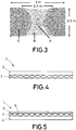
- Figure 3 shows the levels of stress of a net-shaped layer 2 of 5 meters of width and 2,5 meters of height after a high energy impact. As shown, the loads are transferred along the net-shaped layer 2 generating areas of medium (B) and low (C) levels of stress from a high level of stress (A). This way, the net-shaped layer 2 provides a panel structure 1 optimized for transferring loads caused by a high energy impact.
- the net-shaped layer 2 acts as a barrier in case of a high energy impact, spreading the loads of the impact over the entire layer, and minimizing the damage contention.
- the panel structure 1 comprises a composite layer 3, 4 and a net-shaped layer 2 attached to the composite layer 3, 4.
- the net-shaped layer 2 is attached to an inner surface of an outer composite layer 3.
- the net-shaped layer 2 is added internally, for instance, being attached to the frames of the aircraft.
- the net-shaped layer 2 can be added to the aircraft baseline structure by means of rivets or bolts.
- the net-shaped layer 2 is attached to an outer surface of an inner composite layer 4.
- the net-shaped layer 2 is externally added, also, by means of rivets or bolts.
- the panel structure 1 further comprises a laminate sheet material 5 joined to the net-shaped layer 2. Also, and according to a preferred embodiment, the panel structure 1 further comprises a foam material 6 to fill in the net-shaped layer 2.
- the laminate sheet material 5 offers a smooth surface in order to fit the aerodynamic requirements of the panel structure 1. Also, the net-shaped layer 2 may be filled with a foam 6 or other light material to achieve an external smooth surface.
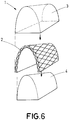
- Figure 6 shows a preferred embodiment for the manufacturing method of the invention.
- the method for manufacturing a panel structure 1 for an aircraft comprises the steps of providing at least one layer of composite material 3, 4, providing at least one net-shaped layer 2, the net-shaped layer 2 comprising a material suitable to improve the impact resistance of the at least one composite layer 3, 4, and attaching the net-shaped layer 2 to the at least one composite layer 3, 4 to form an impact reinforced panel structure 1.
- the net-shaped layer 2 is attached to two layers of composite material 3, 4.
- the method comprises providing an inner 4 and an outer layer of composite material 3, providing a net-shaped layer 2, the net-shaped layer 2 comprising a material suitable to improve the impact resistance of the composite layers 3, 4, and attaching the net-shaped layer 2 to the two composite layers 3, 4 to form an impact reinforced panel structure 1.
Landscapes
- Engineering & Computer Science (AREA)
- Aviation & Aerospace Engineering (AREA)
- Mechanical Engineering (AREA)
- Manufacturing & Machinery (AREA)
- Transportation (AREA)
- Laminated Bodies (AREA)
Abstract
Description
- The present invention refers in general to panel structures for the manufacture of an aircraft, in particular, for its fuselage and empennage section.
- More in particular, it is an object of the present invention to provide a reinforced panel structure for an aircraft, which is capable of withstanding high energy impacts, such as a bird strike, a blade release, or an engine debris impact, with a minimized damage.
- The invention also refers to a method for manufacturing such a panel structure.
- The use of composite materials formed by an organic matrix and unidirectionally orientated fibres, such as Carbon Fibre Reinforced Plastic (CFRP), in the manufacture of structural components of an aircraft, for example fuselage skin panels, torsion boxes, stringers, ribs, spars etc., is well known in the aeronautical industry.
- Typically, skin panels are stiffened by means of several stringers longitudinally arranged, in order to provide strength and guarantee a proper buckling behavior of the skin panels. The stringers are conventionally co-cured, co-bonded, secondarily bonded or bolted to the skin panel.
- These reinforced panels must be designed to meet both aerodynamics and structural requirements, such as a bird collision or blade release.
- As known, bird-plane collisions during flight, take-off and landing happens every day, jeopardizing people and aircraft integrity.
- Also, in propeller aircrafts, blades may break, in part or completely, or be entirely released from a propeller hub. Usually, these releases lead to serious damages in the aircraft structure and/or its systems due to the impact, and to unbalanced situations for the engine due to the broken or released blade.
- For that, airworthiness authorities have requested aircraft manufacturers to consider the impact scenario due to a bird or a blade collision, in order to guarantee that the aircraft is capable of maintaining flight long enough to reach a landing site.
- Current solutions are mainly based on providing localized reinforcements at spots indicated by debris trajectory studies. No significant modifications of the structure of the aircraft are considered, as penetration in the structure is allowed.
- However, this situation changes if propeller engines are installed far from the central fuselage section, as in the rear section of the fuselage, where skin panels may be thinner and the residual strength after a blade impact may be compromised.
- It would therefore be desirable to provide technical means that comply with airworthiness requirements to ensure a safe continuation of flight and landing of an aircraft that had suffered a collision.
- The present invention overcomes the above mentioned drawbacks by providing a panel structure for an aircraft, which minimizes the damage caused by an impact.
- One aspect of the present invention refers to a panel structure for an aircraft that comprises at least one composite layer and at least one net-shaped layer attached to the at least one composite layer, wherein the net-shaped layer comprises a material suitable to improve the impact resistance of the panel structure.
- Thus, the invention provides a new panel structure designed, including a high-strength internal net/skeleton. Thus, instead of traditional monolithic panels (metallics or composites), the invention provides panels with improved impact resistance performance.
- With this configuration, panels are designed to spread loads through a large area (the net-shaped layer) when a high energy impact is received. This way, the invention offers an impact reinforced panel.
- Another aspect of the invention refers to an aircraft, comprising a fuselage, an empennage, a skin covering the fuselage and the empennage, and a panel structure as described, wherein at least part of the fuselage and/or empennage skin is formed by the panel structure.
- Finally, another aspect of the invention refers to a method for manufacturing a panel structure for an aircraft, comprising the steps of providing at least one layer of composite material, providing at least one net-shaped layer comprising a material suitable to improve the impact resistance of the at least one composite layer, and attaching the at least one net-shaped layer to the at least one composite layer to form an impact reinforced panel structure.
- The method of the invention provides several alternatives for attaching the net-shaped layer to the composite layer.
- The method of the invention provides a simple and cost-effective way of producing an impact reinforced skin panel.
- For a better comprehension of the invention, the following drawings are provided for illustrative and non-limiting purposes, wherein:
-
Figure 1 shows a schematic perspective view of a panel structure, according to a first embodiment of the present invention. -
Figure 2a-2c shows different configurations for the net-shaped layer. -
Figure 3 shows an image in which the load transfer behavior of the net-shaped layer can be appreciated. -
Figure 4 shows a schematic perspective view of a panel structure, according to a second embodiment of the present invention. -
Figure 5 shows a schematic perspective view of a panel structure, according to a third embodiment of the present invention. -
Figure 6 shows a schematic perspective view of the arrangement of the net-shaped layer between two composite layers to form the panel structure ofFigure 1 . -
Figure 1 shows apanel structure 1 for an aircraft according to a preferred embodiment. According to the invention, thepanel structure 1 comprises at least onecomposite layer shaped layer 2 attached to the at least onecomposite layer shaped layer 2 comprises a material suitable to improve the impact resistance of thepanel structure 1. - The
panel structure 1 ofFigure 1 comprises anouter composite layer 3, aninner composite layer 4, and a net-shaped layer 2 arranged between the outer andinner layers - The net-
shaped layer 2 ofFigure 1 is attached to two layers ofcomposite material panel 1. This integration may be done by ATP (Automated Fiber/Tow Placement) in case of having a laminate skin panel (i.e. CFRP laminate). - Preferably, the net-
shaped layer 2 comprises at least one of the following materials: steel, titanium, aluminium, carbon fiber, aramid fibers (Kevlar®), ultra high molecular polyethylene (Dyneema®), PBO (Zylon®). - With these materials, the net-
shaped layer 2 provides an impact protection reinforcement that improves the damage tolerance capacity of a conventional panel skin of an aircraft. Thus, the panel of the invention increases the impact protection performance, and minimizes the damage area due to impacts. - The net-
shaped layer 2 may have different configurations. Preferably, the net-shaped layer 2 has a polygonal configuration, such as a rhomboid configuration as shown inFigure 2a , or square configuration, as shown inFigure 2b . - In a preferred embodiment, the net-
shaped layer 2 is set in knotted form, comprising a plurality ofmeshes 7 defined bycorner knots 8 formed by at least twowires 9. - Also, as shown in
Figure 2c , the net-shaped layer 2 may have a double-chain link configuration. This embodiment provides a higher impact resistance to thepanel structure 1. -
Figure 3 shows the levels of stress of a net-shaped layer 2 of 5 meters of width and 2,5 meters of height after a high energy impact. As shown, the loads are transferred along the net-shaped layer 2 generating areas of medium (B) and low (C) levels of stress from a high level of stress (A). This way, the net-shaped layer 2 provides apanel structure 1 optimized for transferring loads caused by a high energy impact. - Thus, the net-
shaped layer 2 acts as a barrier in case of a high energy impact, spreading the loads of the impact over the entire layer, and minimizing the damage contention. - As shown in
Figures 4 and 5 , and according to another preferred embodiments, thepanel structure 1 comprises acomposite layer shaped layer 2 attached to thecomposite layer - In the embodiment of
Figure 4 , the net-shaped layer 2 is attached to an inner surface of anouter composite layer 3. Thus, the net-shaped layer 2 is added internally, for instance, being attached to the frames of the aircraft. The net-shaped layer 2 can be added to the aircraft baseline structure by means of rivets or bolts. - In the embodiment of
Figure 5 , the net-shaped layer 2 is attached to an outer surface of aninner composite layer 4. Thus, the net-shaped layer 2 is externally added, also, by means of rivets or bolts. - As shown in
Figure 5 , thepanel structure 1 further comprises alaminate sheet material 5 joined to the net-shaped layer 2. Also, and according to a preferred embodiment, thepanel structure 1 further comprises afoam material 6 to fill in the net-shaped layer 2. - The
laminate sheet material 5 offers a smooth surface in order to fit the aerodynamic requirements of thepanel structure 1. Also, the net-shaped layer 2 may be filled with afoam 6 or other light material to achieve an external smooth surface. - Finally,
Figure 6 shows a preferred embodiment for the manufacturing method of the invention. - According to the invention, the method for manufacturing a
panel structure 1 for an aircraft comprises the steps of providing at least one layer ofcomposite material layer 2, the net-shapedlayer 2 comprising a material suitable to improve the impact resistance of the at least onecomposite layer layer 2 to the at least onecomposite layer panel structure 1. - Preferably, and as shown in
Figure 6 , the net-shapedlayer 2 is attached to two layers ofcomposite material composite material 3, providing a net-shapedlayer 2, the net-shapedlayer 2 comprising a material suitable to improve the impact resistance of thecomposite layers layer 2 to the twocomposite layers panel structure 1.
Claims (12)
- Panel structure (1) for an aircraft comprising at least one composite layer (3, 4) and at least one net-shaped layer (2) attached to the at least one composite layer (3, 4), wherein the net-shaped layer (2) comprises a material suitable to improve the impact resistance of the panel structure (1).
- Panel structure (1) for an aircraft, according to claim 1, wherein the net-shaped layer (2) comprises at least one of the following materials: steel, titanium, aluminium, carbon fiber, aramid fibers (Kevlar®), ultra high molecular polyethylene (Dyneema®), PBO (Zylon®).
- Panel structure (1) for an aircraft, according to any claim 1 or 2, wherein the net-shaped layer (2) has a polygonal configuration, such as a rhomboid or square configuration.
- Panel structure (1) for an aircraft, according to any of the preceding claims, wherein the net-shaped layer (2) is set in knotted form, comprising a plurality of meshes (7) defined by corner knots (8) formed by at least two wires (9).
- Panel structure (1) for an aircraft, according to any of the preceding claims, wherein the net-shaped layer (2) is attached to two layers of composite material (3, 4).
- Panel structure (1) for an aircraft, according to any of claims 1-4, further comprising a laminate sheet material (5) joined to the net-shaped layer (2).
- Panel structure (1) for an aircraft, according to claim 6, wherein the net-shaped layer (2) is filled with a foam material (6).
- An aircraft, comprising a fuselage, an empennage, a skin covering the fuselage and the empennage, and a panel structure (1) according to any of the preceding claims, wherein at least part of the fuselage and/or empennage skin is formed by the panel structure (1).
- Method for manufacturing a panel structure (1) for an aircraft, comprising the steps of:providing at least one layer of composite material (3, 4),providing at least one net-shaped layer (2), the net-shaped layer (2) comprising a material suitable to improve the impact resistance of the at least one composite layer (3, 4),attaching the net-shaped layer (2) to the at least one composite layer (3, 4) to form an impact reinforced panel structure (1).
- Method according to claim 9, wherein the net-shaped layer (2) is attached to two layers of composite material (3, 4).
- Method according to any of claims 9, further comprising a laminate sheet material (5) joined to the net-shaped layer (2).
- Method according to claim 11, wherein the net-shaped layer (2) is filled with a foam material (6).
Priority Applications (5)
| Application Number | Priority Date | Filing Date | Title |
|---|---|---|---|
| ES16382507T ES2822933T3 (en) | 2016-11-04 | 2016-11-04 | Panel structure for an aircraft and its manufacturing process |
| EP16382507.8A EP3318481B1 (en) | 2016-11-04 | 2016-11-04 | Panel structure for an aircraft and manufacturing method thereof |
| US15/803,559 US20180127081A1 (en) | 2016-11-04 | 2017-11-03 | Panel structure for an aircraft and manufacturing method thereof |
| CA2984697A CA2984697A1 (en) | 2016-11-04 | 2017-11-03 | Panel structure for an aircraft and manufacturing method thereof |
| CN201711077268.5A CN108016600B (en) | 2016-11-04 | 2017-11-06 | Panel structure for an aircraft and method for the production thereof |
Applications Claiming Priority (1)
| Application Number | Priority Date | Filing Date | Title |
|---|---|---|---|
| EP16382507.8A EP3318481B1 (en) | 2016-11-04 | 2016-11-04 | Panel structure for an aircraft and manufacturing method thereof |
Publications (2)
| Publication Number | Publication Date |
|---|---|
| EP3318481A1 true EP3318481A1 (en) | 2018-05-09 |
| EP3318481B1 EP3318481B1 (en) | 2020-07-08 |
Family
ID=57249760
Family Applications (1)
| Application Number | Title | Priority Date | Filing Date |
|---|---|---|---|
| EP16382507.8A Active EP3318481B1 (en) | 2016-11-04 | 2016-11-04 | Panel structure for an aircraft and manufacturing method thereof |
Country Status (5)
| Country | Link |
|---|---|
| US (1) | US20180127081A1 (en) |
| EP (1) | EP3318481B1 (en) |
| CN (1) | CN108016600B (en) |
| CA (1) | CA2984697A1 (en) |
| ES (1) | ES2822933T3 (en) |
Cited By (3)
| Publication number | Priority date | Publication date | Assignee | Title |
|---|---|---|---|---|
| EP3733507A1 (en) | 2019-04-29 | 2020-11-04 | Airbus Operations GmbH | Leading-edge component for an aircraft |
| WO2020221692A1 (en) | 2019-04-29 | 2020-11-05 | Airbus Operations Gmbh | Leading-edge component for an aircraft |
| WO2020239780A1 (en) | 2019-05-28 | 2020-12-03 | Airbus Operations Gmbh | Leading-edge component for an aircraft |
Families Citing this family (10)
| Publication number | Priority date | Publication date | Assignee | Title |
|---|---|---|---|---|
| US10875623B2 (en) | 2018-07-03 | 2020-12-29 | Goodrich Corporation | High temperature thermoplastic pre-impregnated structure for aircraft heated floor panel |
| US10920994B2 (en) | 2018-07-03 | 2021-02-16 | Goodrich Corporation | Heated floor panels |
| US11273897B2 (en) | 2018-07-03 | 2022-03-15 | Goodrich Corporation | Asymmetric surface layer for floor panels |
| US10899427B2 (en) | 2018-07-03 | 2021-01-26 | Goodrich Corporation | Heated floor panel with impact layer |
| US11376811B2 (en) | 2018-07-03 | 2022-07-05 | Goodrich Corporation | Impact and knife cut resistant pre-impregnated woven fabric for aircraft heated floor panels |
| EP4015198A1 (en) * | 2020-12-16 | 2022-06-22 | Airbus Operations, S.L.U. | A reinforced composite laminate and method for manufacturing thereof |
| CN113911380A (en) * | 2021-09-15 | 2022-01-11 | 中国飞机强度研究所 | Bird collision resisting device applied to airplane wing |
| CN113955071B (en) * | 2021-10-09 | 2024-04-26 | 中电科芜湖通用航空产业技术研究院有限公司 | Aircraft fuselage, forming method thereof and aircraft |
| CN114951735B (en) * | 2022-06-14 | 2023-06-16 | 湖北三江航天红阳机电有限公司 | Processing method of composite cabin section |
| TR2023018321A1 (en) * | 2023-12-25 | 2025-07-21 | Tusas Tuerk Havacilik Ve Uzay Sanayii Anonim Sirketi | A protective mechanism. |
Citations (5)
| Publication number | Priority date | Publication date | Assignee | Title |
|---|---|---|---|---|
| US2371754A (en) * | 1942-04-22 | 1945-03-20 | North American Aviation Inc | Stiffened material |
| WO1990001857A1 (en) * | 1988-08-15 | 1990-02-22 | Saab-Scania Aktiebolag | Device for diverting static electricity |
| EP1475304A1 (en) * | 2003-05-09 | 2004-11-10 | Pilatus Flugzeugwerke Ag | Aircraft wing |
| US20080258009A1 (en) * | 2007-03-30 | 2008-10-23 | Airbus Espana, S.L.. | Leading edge for aircraft made of reinforced composite material |
| EP2196309A1 (en) * | 2008-12-09 | 2010-06-16 | Alenia Aeronautica S.P.A. | Leading edge for aircraft wings and empennages |
Family Cites Families (33)
| Publication number | Priority date | Publication date | Assignee | Title |
|---|---|---|---|---|
| US1409982A (en) * | 1919-09-10 | 1922-03-21 | Ernest D Walen | Airplane wing |
| US1717390A (en) * | 1927-07-02 | 1929-06-18 | Andrew A Kucher | Aircraft |
| US3565740A (en) * | 1966-05-06 | 1971-02-23 | Trw Inc | Reinforcement form for use in structural composites,ablative structures and the like |
| US4170675A (en) * | 1977-05-02 | 1979-10-09 | Flexipane Limited | Reinforced flexible panels comprising plastic sheeting on opposed sides of a mesh layer and a metal foil layer in association with a plastic sheet layer |
| US4230293A (en) * | 1978-08-02 | 1980-10-28 | Boeing Commercial Airplane Company | Composite structure and method of making |
| US4472086A (en) * | 1981-02-26 | 1984-09-18 | Burlington Industries Inc. | Geotextile fabric construction |
| US4448832A (en) * | 1983-04-25 | 1984-05-15 | Kidwell William J | Dimensionally woven composite |
| US4671841A (en) * | 1986-01-06 | 1987-06-09 | Rohr Industries, Inc. | Method of making an acoustic panel with a triaxial open-weave face sheet |
| US5082701A (en) * | 1987-12-09 | 1992-01-21 | Quadrax Corporation | Multi-directional, light-weight, high-strength interlaced material and method of making the material |
| DE69434917T2 (en) * | 1993-05-04 | 2007-11-08 | Foster-Miller, Inc., Waltham | GRID-BASED PLATE WITH FOAM CORE |
| US20060084336A1 (en) * | 1999-08-10 | 2006-04-20 | Warwick Mills, Inc. | High strength lightweight composite fabric with low gas permeability |
| JP3894035B2 (en) * | 2001-07-04 | 2007-03-14 | 東レ株式会社 | Carbon fiber reinforced substrate, preform and composite material comprising the same |
| US7300693B2 (en) * | 2003-09-04 | 2007-11-27 | The Boeing Company | Resin infused transparent skin panel and method of making same |
| US7563497B2 (en) * | 2004-12-27 | 2009-07-21 | Mkp Structural Design Associates, Inc. | Lightweight, rigid composite structures |
| US7837919B2 (en) * | 2005-09-28 | 2010-11-23 | Lockheed Martin Corporation | System, method, apparatus, and applications for open cell woven structural supports |
| US7805213B2 (en) * | 2005-10-06 | 2010-09-28 | Peter Thomas Schwenn | Weave, a utility method for designing and fabricating 3D structural shells, solids and their assemblages, without limitations on shape, scale, strength or material |
| US8618004B2 (en) * | 2006-03-16 | 2013-12-31 | Masanori Kubota | Multifunctional composites |
| US20120088050A1 (en) * | 2007-01-16 | 2012-04-12 | Berry Plastics Corporation | Reinforced flame retardant film for blast resistance protection |
| US9511571B2 (en) * | 2007-01-23 | 2016-12-06 | The Boeing Company | Composite laminate having a damping interlayer and method of making the same |
| WO2009023644A1 (en) * | 2007-08-13 | 2009-02-19 | Smart Nanomaterials, Llc | Nano-enhanced smart panel |
| EP2693158B1 (en) * | 2007-10-31 | 2017-12-13 | DSM IP Assets B.V. | Material sheet and process for its preparation |
| DE202009006966U1 (en) * | 2009-04-14 | 2010-09-02 | Gummiwerk Kraiburg Gmbh & Co. Kg | Composite components made of thermosetting resins and elastomers |
| US20110117309A1 (en) * | 2009-11-16 | 2011-05-19 | Mkp Structural Design Associates, Inc. | Biomimetic tendon-reinforced (btr) composite materials |
| ES2689399T3 (en) * | 2010-04-12 | 2018-11-13 | Airbus Operations Gmbh | Section of profiled plates for use as an outer wall of an aerodynamic body, as well as dynamic body component with a fluid aspiration device |
| DE102011006977A1 (en) * | 2011-04-07 | 2012-10-11 | Airbus Operations Gmbh | Method for producing a fiber composite component, reinforcing element and fiber composite component |
| US9475258B2 (en) * | 2012-06-15 | 2016-10-25 | The Boeing Company | Multiple-resin composite structures and methods of producing the same |
| US9511562B2 (en) * | 2012-07-03 | 2016-12-06 | Rohr, Inc. | Nanoreinforced films and laminates for aerospace structures |
| JP5847033B2 (en) * | 2012-07-19 | 2016-01-20 | 株式会社Shindo | Carbon fiber stitch substrate and wet prepreg using the same |
| US9528279B2 (en) * | 2014-09-29 | 2016-12-27 | Kenneth A. Roy | Entangled net product with crumb |
| JP6386329B2 (en) * | 2014-10-06 | 2018-09-05 | テイ・エス テック株式会社 | Skin material for vehicle seats |
| EP3397479A1 (en) * | 2015-12-31 | 2018-11-07 | Firestone Building Products Co., LLC | Polyolefin thermoplastic roofing membranes with improved burn resistivity |
| EP3210883B1 (en) * | 2016-02-29 | 2020-01-29 | Airbus Operations, S.L. | Aircraft airfoil having a stitched trailing edge and manufacturing method thereof |
| CN106273902B (en) * | 2016-08-05 | 2018-08-07 | 深圳航天科技创新研究院 | A kind of aluminium foam sandwich structural composite material and preparation method thereof |
-
2016
- 2016-11-04 EP EP16382507.8A patent/EP3318481B1/en active Active
- 2016-11-04 ES ES16382507T patent/ES2822933T3/en active Active
-
2017
- 2017-11-03 CA CA2984697A patent/CA2984697A1/en active Pending
- 2017-11-03 US US15/803,559 patent/US20180127081A1/en not_active Abandoned
- 2017-11-06 CN CN201711077268.5A patent/CN108016600B/en not_active Expired - Fee Related
Patent Citations (5)
| Publication number | Priority date | Publication date | Assignee | Title |
|---|---|---|---|---|
| US2371754A (en) * | 1942-04-22 | 1945-03-20 | North American Aviation Inc | Stiffened material |
| WO1990001857A1 (en) * | 1988-08-15 | 1990-02-22 | Saab-Scania Aktiebolag | Device for diverting static electricity |
| EP1475304A1 (en) * | 2003-05-09 | 2004-11-10 | Pilatus Flugzeugwerke Ag | Aircraft wing |
| US20080258009A1 (en) * | 2007-03-30 | 2008-10-23 | Airbus Espana, S.L.. | Leading edge for aircraft made of reinforced composite material |
| EP2196309A1 (en) * | 2008-12-09 | 2010-06-16 | Alenia Aeronautica S.P.A. | Leading edge for aircraft wings and empennages |
Cited By (5)
| Publication number | Priority date | Publication date | Assignee | Title |
|---|---|---|---|---|
| EP3733507A1 (en) | 2019-04-29 | 2020-11-04 | Airbus Operations GmbH | Leading-edge component for an aircraft |
| WO2020221692A1 (en) | 2019-04-29 | 2020-11-05 | Airbus Operations Gmbh | Leading-edge component for an aircraft |
| US11230365B2 (en) | 2019-04-29 | 2022-01-25 | Airbus Operations Gmbh | Leading-edge component for an aircraft |
| US11873095B2 (en) | 2019-04-29 | 2024-01-16 | Airbus Operations Gmbh | Leading-edge component for an aircraft |
| WO2020239780A1 (en) | 2019-05-28 | 2020-12-03 | Airbus Operations Gmbh | Leading-edge component for an aircraft |
Also Published As
| Publication number | Publication date |
|---|---|
| CN108016600B (en) | 2022-10-18 |
| US20180127081A1 (en) | 2018-05-10 |
| CA2984697A1 (en) | 2018-05-04 |
| ES2822933T3 (en) | 2021-05-05 |
| CN108016600A (en) | 2018-05-11 |
| EP3318481B1 (en) | 2020-07-08 |
Similar Documents
| Publication | Publication Date | Title |
|---|---|---|
| EP3318481B1 (en) | Panel structure for an aircraft and manufacturing method thereof | |
| EP2774839B1 (en) | Improved impact resistant and damage tolerant aircraft fuselage | |
| EP2772351B1 (en) | Composite laminated plate having reduced crossply angle | |
| EP2117922B1 (en) | Compliant panel for aircraft | |
| EP2130762B1 (en) | Wing and empennage leading edge structure made of thermoplastic material with a stiffened double-shell configuration | |
| US9359085B2 (en) | Aircraft with fuselage-mounted engines and an internal shield | |
| EP3248864B1 (en) | Armoured leading edge and manufacturing method thereof | |
| US20140231586A1 (en) | High-wing-aircraft fuselage support structure | |
| EP3546207B1 (en) | Energy absorbing composite panels | |
| EP3281861A1 (en) | A rotary wing aircraft with a fuselage that comprises at least one structural stiffened panel | |
| EP2700574B1 (en) | Passive load alleviation for a fiber reinforced wing box of an aircraft with a stiffened shell structure | |
| US10604226B2 (en) | Shielded structure for aircraft | |
| EP2818415B1 (en) | Panel member for an airframe | |
| EP3450302B1 (en) | Energy-absorbing under-floor airframe | |
| CN109455290A (en) | A kind of cargo deck lower part endergonic structure unit for fitting pendant property for improving aircraft | |
| EP3106381B1 (en) | Aircraft with a protective shield against an engine blade release | |
| NL2038661B1 (en) | Anti-ballistic structural panel | |
| EP3756880A1 (en) | Fire protection device for an aircraft | |
| CA3014235A1 (en) | Energy-absorbing under-floor airframe |
Legal Events
| Date | Code | Title | Description |
|---|---|---|---|
| PUAI | Public reference made under article 153(3) epc to a published international application that has entered the european phase |
Free format text: ORIGINAL CODE: 0009012 |
|
| STAA | Information on the status of an ep patent application or granted ep patent |
Free format text: STATUS: THE APPLICATION HAS BEEN PUBLISHED |
|
| AK | Designated contracting states |
Kind code of ref document: A1 Designated state(s): AL AT BE BG CH CY CZ DE DK EE ES FI FR GB GR HR HU IE IS IT LI LT LU LV MC MK MT NL NO PL PT RO RS SE SI SK SM TR |
|
| AX | Request for extension of the european patent |
Extension state: BA ME |
|
| STAA | Information on the status of an ep patent application or granted ep patent |
Free format text: STATUS: REQUEST FOR EXAMINATION WAS MADE |
|
| 17P | Request for examination filed |
Effective date: 20181031 |
|
| RBV | Designated contracting states (corrected) |
Designated state(s): AL AT BE BG CH CY CZ DE DK EE ES FI FR GB GR HR HU IE IS IT LI LT LU LV MC MK MT NL NO PL PT RO RS SE SI SK SM TR |
|
| STAA | Information on the status of an ep patent application or granted ep patent |
Free format text: STATUS: EXAMINATION IS IN PROGRESS |
|
| 17Q | First examination report despatched |
Effective date: 20190313 |
|
| GRAP | Despatch of communication of intention to grant a patent |
Free format text: ORIGINAL CODE: EPIDOSNIGR1 |
|
| GRAJ | Information related to disapproval of communication of intention to grant by the applicant or resumption of examination proceedings by the epo deleted |
Free format text: ORIGINAL CODE: EPIDOSDIGR1 |
|
| GRAJ | Information related to disapproval of communication of intention to grant by the applicant or resumption of examination proceedings by the epo deleted |
Free format text: ORIGINAL CODE: EPIDOSDIGR1 |
|
| STAA | Information on the status of an ep patent application or granted ep patent |
Free format text: STATUS: GRANT OF PATENT IS INTENDED |
|
| GRAP | Despatch of communication of intention to grant a patent |
Free format text: ORIGINAL CODE: EPIDOSNIGR1 |
|
| RIN1 | Information on inventor provided before grant (corrected) |
Inventor name: GOYA ABAURREA, PABLO Inventor name: VOTSIOS, VASILIS Inventor name: TORAL VAZQUEZ, JAVIER Inventor name: FOUINNETAU, MICHEL Inventor name: ROUMEGAS, SYLVAIN Inventor name: MARTINO GONZALEZ, ESTEBAN Inventor name: FOLCH CORTES, DIEGO |
|
| INTG | Intention to grant announced |
Effective date: 20200131 |
|
| GRAS | Grant fee paid |
Free format text: ORIGINAL CODE: EPIDOSNIGR3 |
|
| GRAA | (expected) grant |
Free format text: ORIGINAL CODE: 0009210 |
|
| STAA | Information on the status of an ep patent application or granted ep patent |
Free format text: STATUS: THE PATENT HAS BEEN GRANTED |
|
| AK | Designated contracting states |
Kind code of ref document: B1 Designated state(s): AL AT BE BG CH CY CZ DE DK EE ES FI FR GB GR HR HU IE IS IT LI LT LU LV MC MK MT NL NO PL PT RO RS SE SI SK SM TR |
|
| REG | Reference to a national code |
Ref country code: CH Ref legal event code: EP Ref country code: AT Ref legal event code: REF Ref document number: 1288185 Country of ref document: AT Kind code of ref document: T Effective date: 20200715 |
|
| REG | Reference to a national code |
Ref country code: DE Ref legal event code: R096 Ref document number: 602016039446 Country of ref document: DE |
|
| REG | Reference to a national code |
Ref country code: IE Ref legal event code: FG4D |
|
| REG | Reference to a national code |
Ref country code: LT Ref legal event code: MG4D |
|
| REG | Reference to a national code |
Ref country code: AT Ref legal event code: MK05 Ref document number: 1288185 Country of ref document: AT Kind code of ref document: T Effective date: 20200708 |
|
| REG | Reference to a national code |
Ref country code: NL Ref legal event code: MP Effective date: 20200708 |
|
| PG25 | Lapsed in a contracting state [announced via postgrant information from national office to epo] |
Ref country code: BG Free format text: LAPSE BECAUSE OF FAILURE TO SUBMIT A TRANSLATION OF THE DESCRIPTION OR TO PAY THE FEE WITHIN THE PRESCRIBED TIME-LIMIT Effective date: 20201008 Ref country code: SE Free format text: LAPSE BECAUSE OF FAILURE TO SUBMIT A TRANSLATION OF THE DESCRIPTION OR TO PAY THE FEE WITHIN THE PRESCRIBED TIME-LIMIT Effective date: 20200708 Ref country code: PT Free format text: LAPSE BECAUSE OF FAILURE TO SUBMIT A TRANSLATION OF THE DESCRIPTION OR TO PAY THE FEE WITHIN THE PRESCRIBED TIME-LIMIT Effective date: 20201109 Ref country code: HR Free format text: LAPSE BECAUSE OF FAILURE TO SUBMIT A TRANSLATION OF THE DESCRIPTION OR TO PAY THE FEE WITHIN THE PRESCRIBED TIME-LIMIT Effective date: 20200708 Ref country code: LT Free format text: LAPSE BECAUSE OF FAILURE TO SUBMIT A TRANSLATION OF THE DESCRIPTION OR TO PAY THE FEE WITHIN THE PRESCRIBED TIME-LIMIT Effective date: 20200708 Ref country code: FI Free format text: LAPSE BECAUSE OF FAILURE TO SUBMIT A TRANSLATION OF THE DESCRIPTION OR TO PAY THE FEE WITHIN THE PRESCRIBED TIME-LIMIT Effective date: 20200708 Ref country code: AT Free format text: LAPSE BECAUSE OF FAILURE TO SUBMIT A TRANSLATION OF THE DESCRIPTION OR TO PAY THE FEE WITHIN THE PRESCRIBED TIME-LIMIT Effective date: 20200708 Ref country code: GR Free format text: LAPSE BECAUSE OF FAILURE TO SUBMIT A TRANSLATION OF THE DESCRIPTION OR TO PAY THE FEE WITHIN THE PRESCRIBED TIME-LIMIT Effective date: 20201009 Ref country code: NO Free format text: LAPSE BECAUSE OF FAILURE TO SUBMIT A TRANSLATION OF THE DESCRIPTION OR TO PAY THE FEE WITHIN THE PRESCRIBED TIME-LIMIT Effective date: 20201008 |
|
| PG25 | Lapsed in a contracting state [announced via postgrant information from national office to epo] |
Ref country code: RS Free format text: LAPSE BECAUSE OF FAILURE TO SUBMIT A TRANSLATION OF THE DESCRIPTION OR TO PAY THE FEE WITHIN THE PRESCRIBED TIME-LIMIT Effective date: 20200708 Ref country code: LV Free format text: LAPSE BECAUSE OF FAILURE TO SUBMIT A TRANSLATION OF THE DESCRIPTION OR TO PAY THE FEE WITHIN THE PRESCRIBED TIME-LIMIT Effective date: 20200708 Ref country code: PL Free format text: LAPSE BECAUSE OF FAILURE TO SUBMIT A TRANSLATION OF THE DESCRIPTION OR TO PAY THE FEE WITHIN THE PRESCRIBED TIME-LIMIT Effective date: 20200708 Ref country code: IS Free format text: LAPSE BECAUSE OF FAILURE TO SUBMIT A TRANSLATION OF THE DESCRIPTION OR TO PAY THE FEE WITHIN THE PRESCRIBED TIME-LIMIT Effective date: 20201108 |
|
| PG25 | Lapsed in a contracting state [announced via postgrant information from national office to epo] |
Ref country code: NL Free format text: LAPSE BECAUSE OF FAILURE TO SUBMIT A TRANSLATION OF THE DESCRIPTION OR TO PAY THE FEE WITHIN THE PRESCRIBED TIME-LIMIT Effective date: 20200708 |
|
| REG | Reference to a national code |
Ref country code: DE Ref legal event code: R097 Ref document number: 602016039446 Country of ref document: DE |
|
| PG25 | Lapsed in a contracting state [announced via postgrant information from national office to epo] |
Ref country code: EE Free format text: LAPSE BECAUSE OF FAILURE TO SUBMIT A TRANSLATION OF THE DESCRIPTION OR TO PAY THE FEE WITHIN THE PRESCRIBED TIME-LIMIT Effective date: 20200708 Ref country code: IT Free format text: LAPSE BECAUSE OF FAILURE TO SUBMIT A TRANSLATION OF THE DESCRIPTION OR TO PAY THE FEE WITHIN THE PRESCRIBED TIME-LIMIT Effective date: 20200708 Ref country code: RO Free format text: LAPSE BECAUSE OF FAILURE TO SUBMIT A TRANSLATION OF THE DESCRIPTION OR TO PAY THE FEE WITHIN THE PRESCRIBED TIME-LIMIT Effective date: 20200708 Ref country code: SM Free format text: LAPSE BECAUSE OF FAILURE TO SUBMIT A TRANSLATION OF THE DESCRIPTION OR TO PAY THE FEE WITHIN THE PRESCRIBED TIME-LIMIT Effective date: 20200708 Ref country code: DK Free format text: LAPSE BECAUSE OF FAILURE TO SUBMIT A TRANSLATION OF THE DESCRIPTION OR TO PAY THE FEE WITHIN THE PRESCRIBED TIME-LIMIT Effective date: 20200708 Ref country code: CZ Free format text: LAPSE BECAUSE OF FAILURE TO SUBMIT A TRANSLATION OF THE DESCRIPTION OR TO PAY THE FEE WITHIN THE PRESCRIBED TIME-LIMIT Effective date: 20200708 |
|
| REG | Reference to a national code |
Ref country code: ES Ref legal event code: FG2A Ref document number: 2822933 Country of ref document: ES Kind code of ref document: T3 Effective date: 20210505 |
|
| PLBE | No opposition filed within time limit |
Free format text: ORIGINAL CODE: 0009261 |
|
| STAA | Information on the status of an ep patent application or granted ep patent |
Free format text: STATUS: NO OPPOSITION FILED WITHIN TIME LIMIT |
|
| PG25 | Lapsed in a contracting state [announced via postgrant information from national office to epo] |
Ref country code: AL Free format text: LAPSE BECAUSE OF FAILURE TO SUBMIT A TRANSLATION OF THE DESCRIPTION OR TO PAY THE FEE WITHIN THE PRESCRIBED TIME-LIMIT Effective date: 20200708 |
|
| 26N | No opposition filed |
Effective date: 20210409 |
|
| PG25 | Lapsed in a contracting state [announced via postgrant information from national office to epo] |
Ref country code: SK Free format text: LAPSE BECAUSE OF FAILURE TO SUBMIT A TRANSLATION OF THE DESCRIPTION OR TO PAY THE FEE WITHIN THE PRESCRIBED TIME-LIMIT Effective date: 20200708 Ref country code: MC Free format text: LAPSE BECAUSE OF FAILURE TO SUBMIT A TRANSLATION OF THE DESCRIPTION OR TO PAY THE FEE WITHIN THE PRESCRIBED TIME-LIMIT Effective date: 20200708 |
|
| REG | Reference to a national code |
Ref country code: CH Ref legal event code: PL |
|
| PG25 | Lapsed in a contracting state [announced via postgrant information from national office to epo] |
Ref country code: LU Free format text: LAPSE BECAUSE OF NON-PAYMENT OF DUE FEES Effective date: 20201104 |
|
| REG | Reference to a national code |
Ref country code: BE Ref legal event code: MM Effective date: 20201130 |
|
| PG25 | Lapsed in a contracting state [announced via postgrant information from national office to epo] |
Ref country code: LI Free format text: LAPSE BECAUSE OF NON-PAYMENT OF DUE FEES Effective date: 20201130 Ref country code: SI Free format text: LAPSE BECAUSE OF FAILURE TO SUBMIT A TRANSLATION OF THE DESCRIPTION OR TO PAY THE FEE WITHIN THE PRESCRIBED TIME-LIMIT Effective date: 20200708 Ref country code: CH Free format text: LAPSE BECAUSE OF NON-PAYMENT OF DUE FEES Effective date: 20201130 |
|
| PG25 | Lapsed in a contracting state [announced via postgrant information from national office to epo] |
Ref country code: IE Free format text: LAPSE BECAUSE OF NON-PAYMENT OF DUE FEES Effective date: 20201104 |
|
| PG25 | Lapsed in a contracting state [announced via postgrant information from national office to epo] |
Ref country code: TR Free format text: LAPSE BECAUSE OF FAILURE TO SUBMIT A TRANSLATION OF THE DESCRIPTION OR TO PAY THE FEE WITHIN THE PRESCRIBED TIME-LIMIT Effective date: 20200708 Ref country code: MT Free format text: LAPSE BECAUSE OF FAILURE TO SUBMIT A TRANSLATION OF THE DESCRIPTION OR TO PAY THE FEE WITHIN THE PRESCRIBED TIME-LIMIT Effective date: 20200708 Ref country code: CY Free format text: LAPSE BECAUSE OF FAILURE TO SUBMIT A TRANSLATION OF THE DESCRIPTION OR TO PAY THE FEE WITHIN THE PRESCRIBED TIME-LIMIT Effective date: 20200708 |
|
| PG25 | Lapsed in a contracting state [announced via postgrant information from national office to epo] |
Ref country code: MK Free format text: LAPSE BECAUSE OF FAILURE TO SUBMIT A TRANSLATION OF THE DESCRIPTION OR TO PAY THE FEE WITHIN THE PRESCRIBED TIME-LIMIT Effective date: 20200708 |
|
| PG25 | Lapsed in a contracting state [announced via postgrant information from national office to epo] |
Ref country code: BE Free format text: LAPSE BECAUSE OF NON-PAYMENT OF DUE FEES Effective date: 20201130 |
|
| PGFP | Annual fee paid to national office [announced via postgrant information from national office to epo] |
Ref country code: GB Payment date: 20231123 Year of fee payment: 8 |
|
| PGFP | Annual fee paid to national office [announced via postgrant information from national office to epo] |
Ref country code: FR Payment date: 20231120 Year of fee payment: 8 Ref country code: DE Payment date: 20231121 Year of fee payment: 8 |
|
| PGFP | Annual fee paid to national office [announced via postgrant information from national office to epo] |
Ref country code: ES Payment date: 20240129 Year of fee payment: 8 |
|
| REG | Reference to a national code |
Ref country code: DE Ref legal event code: R119 Ref document number: 602016039446 Country of ref document: DE |
|
| GBPC | Gb: european patent ceased through non-payment of renewal fee |
Effective date: 20241104 |
|
| PG25 | Lapsed in a contracting state [announced via postgrant information from national office to epo] |
Ref country code: DE Free format text: LAPSE BECAUSE OF NON-PAYMENT OF DUE FEES Effective date: 20250603 |
|
| PG25 | Lapsed in a contracting state [announced via postgrant information from national office to epo] |
Ref country code: GB Free format text: LAPSE BECAUSE OF NON-PAYMENT OF DUE FEES Effective date: 20241104 |
|
| PG25 | Lapsed in a contracting state [announced via postgrant information from national office to epo] |
Ref country code: FR Free format text: LAPSE BECAUSE OF NON-PAYMENT OF DUE FEES Effective date: 20241130 |
|
| REG | Reference to a national code |
Ref country code: ES Ref legal event code: FD2A Effective date: 20251230 |
|
| PG25 | Lapsed in a contracting state [announced via postgrant information from national office to epo] |
Ref country code: ES Free format text: LAPSE BECAUSE OF NON-PAYMENT OF DUE FEES Effective date: 20241105 |