EP3106381B1 - Aircraft with a protective shield against an engine blade release - Google Patents
Aircraft with a protective shield against an engine blade release Download PDFInfo
- Publication number
- EP3106381B1 EP3106381B1 EP15382311.7A EP15382311A EP3106381B1 EP 3106381 B1 EP3106381 B1 EP 3106381B1 EP 15382311 A EP15382311 A EP 15382311A EP 3106381 B1 EP3106381 B1 EP 3106381B1
- Authority
- EP
- European Patent Office
- Prior art keywords
- aircraft
- containers
- engines
- rear fuselage
- aircraft according
- Prior art date
- Legal status (The legal status is an assumption and is not a legal conclusion. Google has not performed a legal analysis and makes no representation as to the accuracy of the status listed.)
- Active
Links
- 230000001681 protective effect Effects 0.000 title 1
- 239000007788 liquid Substances 0.000 claims description 21
- 239000003651 drinking water Substances 0.000 claims description 16
- 235000012206 bottled water Nutrition 0.000 claims description 15
- 239000002351 wastewater Substances 0.000 claims description 15
- 239000012634 fragment Substances 0.000 claims description 14
- 239000002131 composite material Substances 0.000 claims description 7
- 229920000271 Kevlar® Polymers 0.000 claims description 6
- 239000004761 kevlar Substances 0.000 claims description 6
- 238000010521 absorption reaction Methods 0.000 claims description 4
- 239000000446 fuel Substances 0.000 claims description 4
- 239000007769 metal material Substances 0.000 description 4
- 239000000835 fiber Substances 0.000 description 3
- XLYOFNOQVPJJNP-UHFFFAOYSA-N water Substances O XLYOFNOQVPJJNP-UHFFFAOYSA-N 0.000 description 3
- 239000000463 material Substances 0.000 description 2
- 229920000049 Carbon (fiber) Polymers 0.000 description 1
- XAGFODPZIPBFFR-UHFFFAOYSA-N aluminium Chemical compound [Al] XAGFODPZIPBFFR-UHFFFAOYSA-N 0.000 description 1
- 229910052782 aluminium Inorganic materials 0.000 description 1
- 239000004917 carbon fiber Substances 0.000 description 1
- 238000004880 explosion Methods 0.000 description 1
- 239000011159 matrix material Substances 0.000 description 1
- 238000005457 optimization Methods 0.000 description 1
- 229920005992 thermoplastic resin Polymers 0.000 description 1
- 229920001187 thermosetting polymer Polymers 0.000 description 1
Images


Classifications
-
- B—PERFORMING OPERATIONS; TRANSPORTING
- B64—AIRCRAFT; AVIATION; COSMONAUTICS
- B64C—AEROPLANES; HELICOPTERS
- B64C1/00—Fuselages; Constructional features common to fuselages, wings, stabilising surfaces or the like
- B64C1/06—Frames; Stringers; Longerons ; Fuselage sections
- B64C1/068—Fuselage sections
- B64C1/0685—Tail cones
-
- B—PERFORMING OPERATIONS; TRANSPORTING
- B64—AIRCRAFT; AVIATION; COSMONAUTICS
- B64C—AEROPLANES; HELICOPTERS
- B64C7/00—Structures or fairings not otherwise provided for
-
- B—PERFORMING OPERATIONS; TRANSPORTING
- B64—AIRCRAFT; AVIATION; COSMONAUTICS
- B64C—AEROPLANES; HELICOPTERS
- B64C1/00—Fuselages; Constructional features common to fuselages, wings, stabilising surfaces or the like
- B64C1/06—Frames; Stringers; Longerons ; Fuselage sections
-
- B—PERFORMING OPERATIONS; TRANSPORTING
- B64—AIRCRAFT; AVIATION; COSMONAUTICS
- B64D—EQUIPMENT FOR FITTING IN OR TO AIRCRAFT; FLIGHT SUITS; PARACHUTES; ARRANGEMENTS OR MOUNTING OF POWER PLANTS OR PROPULSION TRANSMISSIONS IN AIRCRAFT
- B64D27/00—Arrangement or mounting of power plant in aircraft; Aircraft characterised thereby
- B64D27/02—Aircraft characterised by the type or position of power plant
- B64D27/10—Aircraft characterised by the type or position of power plant of gas-turbine type
- B64D27/14—Aircraft characterised by the type or position of power plant of gas-turbine type within or attached to fuselage
-
- B—PERFORMING OPERATIONS; TRANSPORTING
- B64—AIRCRAFT; AVIATION; COSMONAUTICS
- B64D—EQUIPMENT FOR FITTING IN OR TO AIRCRAFT; FLIGHT SUITS; PARACHUTES; ARRANGEMENTS OR MOUNTING OF POWER PLANTS OR PROPULSION TRANSMISSIONS IN AIRCRAFT
- B64D37/00—Arrangements in connection with fuel supply for power plant
- B64D37/02—Tanks
- B64D37/04—Arrangement thereof in or on aircraft
-
- B—PERFORMING OPERATIONS; TRANSPORTING
- B64—AIRCRAFT; AVIATION; COSMONAUTICS
- B64D—EQUIPMENT FOR FITTING IN OR TO AIRCRAFT; FLIGHT SUITS; PARACHUTES; ARRANGEMENTS OR MOUNTING OF POWER PLANTS OR PROPULSION TRANSMISSIONS IN AIRCRAFT
- B64D45/00—Aircraft indicators or protectors not otherwise provided for
-
- B—PERFORMING OPERATIONS; TRANSPORTING
- B64—AIRCRAFT; AVIATION; COSMONAUTICS
- B64C—AEROPLANES; HELICOPTERS
- B64C1/00—Fuselages; Constructional features common to fuselages, wings, stabilising surfaces or the like
- B64C2001/0054—Fuselage structures substantially made from particular materials
- B64C2001/0072—Fuselage structures substantially made from particular materials from composite materials
-
- Y—GENERAL TAGGING OF NEW TECHNOLOGICAL DEVELOPMENTS; GENERAL TAGGING OF CROSS-SECTIONAL TECHNOLOGIES SPANNING OVER SEVERAL SECTIONS OF THE IPC; TECHNICAL SUBJECTS COVERED BY FORMER USPC CROSS-REFERENCE ART COLLECTIONS [XRACs] AND DIGESTS
- Y02—TECHNOLOGIES OR APPLICATIONS FOR MITIGATION OR ADAPTATION AGAINST CLIMATE CHANGE
- Y02T—CLIMATE CHANGE MITIGATION TECHNOLOGIES RELATED TO TRANSPORTATION
- Y02T50/00—Aeronautics or air transport
- Y02T50/40—Weight reduction
Definitions
- the present invention relates to an aircraft equipped with fuselage-mounted engines and, more particularly, to the protection of said engines against the risk of being impacted by a part detached from the opposite engine in case of a failure.
- Figures 2a and 2b show an aircraft with two engines with unducted propeller blades 13 attached to the rear fuselage 11 by means of pylons 17 and an empennage comprising a vertical tail plane 21 and an upper horizontal tail plane 23 behind the propulsion system.
- Figure 3 shows an aircraft with two turbofan engines 13 attached directly to the rear fuselage 11 and an empennage comprising a vertical tail plane 21 and an upper horizontal tail plane 23 behind the propulsion system.
- failure events such as a Blade Release (BR) event, i.e. an event where an external blade of one engine with unducted propeller blades comes off and hits the fuselage, or an Uncontained Engine Rotor Failure (UERF) event, i.e. an event where a part of the internal rotors of the engine breaks, it is released and hits the fuselage, can generate large damages on the fuselage and also in the opposite engine. In the last case, the effects can be catastrophic.
- BR Blade Release
- UERF Uncontained Engine Rotor Failure
- the certification requirements are very restrictive and are driving both fuselage and systems architectures in order to fulfill safety requirements.
- weight is a fundamental aspect in the aeronautic industry and therefore there is a trend to use structures of a composite material instead of a metallic material even for primary structures such as fuselages.
- composite materials that are most used in the aeronautical industry consist of fibers or fiber bundles embedded in a matrix of thermosetting or thermoplastic resin, in the form of a preimpregnated or "prepreg" material. Their main advantages refer to:
- EP 2610164 A1 discloses an aircraft provided with an internal shield intended to efficiently protect an engine (including systems such as electrical generation and fuel feed that are critical ones) from the risk of being damaged by a detached part from the opposite engine.
- a drawback of said internal shield is that increases significantly the weight of the aircraft.
- the invention provides an aircraft comprising one or more aircraft sub-systems(s) each comprising one or more liquid container(s).
- the aircraft further comprises a rear fuselage having a propulsion system formed by two engines mounted on each side of the rear fuselage.
- the rear fuselage comprises an internal shield located inside the rear fuselage in a suitable place for covering the possible trajectories of fragments detached from one engine in a failure event that would impact critical elements of the opposite engine.
- the internal shield comprises an ensemble of liquid containers located in said possible trajectories such that the total volume of liquid contained in the ensemble is sufficient to provide the energy absorption capability required for stopping said fragments.
- the internal shield is mainly made with elements of existing sub-systems in the aircraft the weigh increase involved by its inclusion in the aircraft is small.
- said liquid containers belong to the potable water and/or to the waste water sub-systems of the aircraft and they are, preferably, arranged, staggered in a first column of potable water containers and in a second column of waste water containers.
- These two columns can be particularly located at both sides of the vertical symmetry plane of the rear fuselage of the aircraft and arranged so that the internal shield always contains, globally, the same volume of water distributed whether in the potable water column or in the waste water column in a manner that a fragment detached from one of said engines would be stopped by a potable water container or a waste water container partially or totally filled with, respectively, potable water or waste water.
- the invention is applicable to any kind of aircraft equipped with two engines mounted on each side of the rear fuselage such as those illustrated in Figures 1, 2 and 3 .
- the critical elements of the opposite engine may be easily impacted by a detached part of one engine because of their proximity and the lack of strong and massive structural items between both engines.
- the involved risk is a failure of the opposite engine which would lead to a catastrophic event.
- the set of possible trajectories 29 (see Figure 4 ) of detached fragments to be considered is obtained associating to a pre-selection of fragments taking into account all engine stages (rotor, turbine, propellers) their possible trajectories in a failure event.
- the invention proposes an internal shield 31 comprising liquid containers of one of the liquids used in an aircraft sub-system with enough liquid for providing the energy absorption capability required for stopping the fragments detached from one of said engines 13 in a failure event that would impact on critical elements of the opposite engine profiting that a liquid is a massive and good means for absorbing the energy of said fragments.
- the internal shield 31 shall be located in a suitable position to stop said fragments.
- said liquid containers belong to the potable water and waste water subsystems of the aircraft. It is considered that a configuration of said subsystems with containers in the rear part of the aircraft (an unpressurised zone) can satisfy the typical functional requirements of said sub-systems and also to maintain enough liquid in the internal shield 31 to guarantee the required energy absorption capability.
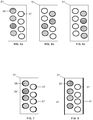
- the internal shield 31 is formed by potable water containers 35 in a first column at the left side and waste water containers 37 in a second column at the right side arranged staggered.
- the potable water and waste water subsystems are arranged for managing the transfer of water so that, for example, at the beginning of a flight all the potable water containers 35 would be filled as illustrated in Figure 6a ; at a later time, the first two potable water containers 35 would be empty and the first two waste water containers 37 would be filled as shown in Figure 6b . At the end of the flight all potable water containers 35 would be empty and all waste water containers 37 would be filled as shown in Figure 6c . Therefore the internal shield 31 always contains, globally, the same volume of water and this volume is distributed in both columns in a manner that covers the space affected by any detached fragments of an engine.
- the potable and waste water containers 35, 37 are, preferably, cylindrical containers arranged parallel to the vertical symmetry plane A-A of the rear fuselage. They may be covered with thin composite Kevlar type skins 35', 37' (see Figure 7 ) in their lateral outer sides in order to spread the dynamic load on said containers 35, 37 on wider area.
- the internal shield 31 may comprise fuel containers duly protected against explosion risks.
- the internal shield 31 includes, as shown in Figure 8 , two layers of Kevlar 41, 41' arranged at both its sides so as to cover the ensemble of liquid containers 35, 37.
- Figure 8 shows the same arrangement of containers 35, 37 of Figures 6a, 6b, 6c and 7
- the internal shield 31 may comprise an ensemble of liquid containers arranged differently.
- the internal shield 31 is preferably located in a central position occupying a space at both sides of the vertical plane of symmetry A-A that covers the possible trajectories of said fragments.
- the main advantage of the shield of the invention with respect to the shield disclosed in EP 2610164 A1 is that does not involve a significant weight increase of the aircraft weight due to the use of means of aircraft sub-systems.
Description
- The present invention relates to an aircraft equipped with fuselage-mounted engines and, more particularly, to the protection of said engines against the risk of being impacted by a part detached from the opposite engine in case of a failure.
- There are known aircraft equipped with two engines mounted on the rear fuselage such as those shown in
Figures 1a, 1b, 2a, 2b and3 . -
Figures 1a and 1b show an aircraft with twoturbofan engines 13 attached to therear fuselage 11 by means ofpylons 17 and an empennage comprising avertical tail plane 21 and an upperhorizontal tail plane 23 behind the propulsion system. -
Figures 2a and 2b show an aircraft with two engines with unductedpropeller blades 13 attached to therear fuselage 11 by means ofpylons 17 and an empennage comprising avertical tail plane 21 and an upperhorizontal tail plane 23 behind the propulsion system. -
Figure 3 shows an aircraft with twoturbofan engines 13 attached directly to therear fuselage 11 and an empennage comprising avertical tail plane 21 and an upperhorizontal tail plane 23 behind the propulsion system. - In these aircraft, failure events such as a Blade Release (BR) event, i.e. an event where an external blade of one engine with unducted propeller blades comes off and hits the fuselage, or an Uncontained Engine Rotor Failure (UERF) event, i.e. an event where a part of the internal rotors of the engine breaks, it is released and hits the fuselage, can generate large damages on the fuselage and also in the opposite engine. In the last case, the effects can be catastrophic.
- Although engine manufacturers are making efforts to reduce the probability of said failure events, experience shows that UERF and BR events that can lead to catastrophic events continue to occur.
- The certification requirements are very restrictive and are driving both fuselage and systems architectures in order to fulfill safety requirements.
- As is well known, weight is a fundamental aspect in the aeronautic industry and therefore there is a trend to use structures of a composite material instead of a metallic material even for primary structures such as fuselages.
- The composite materials that are most used in the aeronautical industry consist of fibers or fiber bundles embedded in a matrix of thermosetting or thermoplastic resin, in the form of a preimpregnated or "prepreg" material. Their main advantages refer to:
- Their high specific strength with respect to metallic materials. It is the strength/weight equation.
- Their excellent behavior under fatigue loads.
- The possibilities of structural optimization thanks to the anisotropy of the material and the possibility of combining fibers with different orientations, allowing the design of the elements with different mechanical properties to be adjusted to the different needs in terms of applied loads.
- The disadvantage of the usual composite materials made of carbon fibers compared to conventional light weight metallic materials like the aluminum, is their lower impact resistance and damage tolerance capabilities. No plasticity behavior as on metallic materials is present in composite materials and they are not able to absorb high strain energy amounts when deforming.
- There is therefore a need of aircraft structures capable to satisfy the safety requirements particularly when the fuselage is made up of composite materials.
-
EP 2610164 A1 discloses an aircraft provided with an internal shield intended to efficiently protect an engine (including systems such as electrical generation and fuel feed that are critical ones) from the risk of being damaged by a detached part from the opposite engine. A drawback of said internal shield is that increases significantly the weight of the aircraft. - The present invention is addressed to the solution of this drawback.
- In one aspect, the invention provides an aircraft comprising one or more aircraft sub-systems(s) each comprising one or more liquid container(s). The aircraft further comprises a rear fuselage having a propulsion system formed by two engines mounted on each side of the rear fuselage. The rear fuselage comprises an internal shield located inside the rear fuselage in a suitable place for covering the possible trajectories of fragments detached from one engine in a failure event that would impact critical elements of the opposite engine. The internal shield comprises an ensemble of liquid containers located in said possible trajectories such that the total volume of liquid contained in the ensemble is sufficient to provide the energy absorption capability required for stopping said fragments. As the internal shield is mainly made with elements of existing sub-systems in the aircraft the weigh increase involved by its inclusion in the aircraft is small.
- In an embodiment said liquid containers belong to the potable water and/or to the waste water sub-systems of the aircraft and they are, preferably, arranged, staggered in a first column of potable water containers and in a second column of waste water containers. These two columns can be particularly located at both sides of the vertical symmetry plane of the rear fuselage of the aircraft and arranged so that the internal shield always contains, globally, the same volume of water distributed whether in the potable water column or in the waste water column in a manner that a fragment detached from one of said engines would be stopped by a potable water container or a waste water container partially or totally filled with, respectively, potable water or waste water.
- Other characteristics and advantages of the present invention will be clear from the following detailed description of embodiments illustrative of its object in relation to the attached figures.
-
-
Figures 1a and 1b are, respectively, schematic perspective and plan views of the rear part of an aircraft whose fuselage is equipped with turbofan engines connected to the fuselage by pylons. -
Figures 2a and 2b are, respectively, schematic perspective and plan views of the rear part of an aircraft whose fuselage is equipped with engines with unducted propeller blades connected to the fuselage by pylons. -
Figure 3 is a perspective view of the rear part of an aircraft whose fuselage is equipped with turbofan engines connected directly to the fuselage. -
Figure 4 is a perspective view of the rear part of an aircraft showing possible trajectories of detached fragments from one engine that can impact on the opposite engine. -
Figure 5 is a schematic plan view of the rear part of an aircraft whose fuselage is equipped with engines with unducted propeller blades connected to the fuselage by pylons and that includes an internal shield against an engine blade release. -
Figures 6a, 6b and 6c are schematic sectional views illustrating an internal shield formed by liquid containers according to the present invention in three different stages of a flight. -
Figure 7 is a schematic sectional view illustrating an internal shield formed by liquid containers according to the present invention that include a Kevlar skin in the outer lateral sides of the containers. -
Figure 8 is a schematic sectional view illustrating an internal shield according to the present invention that includes Kevlar layers on its sides facing the engines. - The invention is applicable to any kind of aircraft equipped with two engines mounted on each side of the rear fuselage such as those illustrated in
Figures 1, 2 and3 . - In these aircraft, in the case of an engine failure, the critical elements of the opposite engine (those elements that cannot be lost when an engine fails such as the electrical generation, the engine fuel feed and the engine blades) may be easily impacted by a detached part of one engine because of their proximity and the lack of strong and massive structural items between both engines. The involved risk is a failure of the opposite engine which would lead to a catastrophic event.
- This risk is not avoided by impact resistant and damage tolerant fuselages such as those disclosed in
WO 2009/068638 andUS 2011/233335 because their main objective is not stopping completely any detached part of an engine that damages the fuselage but to provide the fuselage with the strength needed for a "get home mission" with one operating engine. - The set of possible trajectories 29 (see
Figure 4 ) of detached fragments to be considered is obtained associating to a pre-selection of fragments taking into account all engine stages (rotor, turbine, propellers) their possible trajectories in a failure event. - The strength of the internal shield depends on the level of energy of the fragments that need to be stopped according to the certification requirements and other relevant factors.
- The invention proposes an
internal shield 31 comprising liquid containers of one of the liquids used in an aircraft sub-system with enough liquid for providing the energy absorption capability required for stopping the fragments detached from one of saidengines 13 in a failure event that would impact on critical elements of the opposite engine profiting that a liquid is a massive and good means for absorbing the energy of said fragments. Theinternal shield 31 shall be located in a suitable position to stop said fragments. - In an embodiment said liquid containers belong to the potable water and waste water subsystems of the aircraft. It is considered that a configuration of said subsystems with containers in the rear part of the aircraft (an unpressurised zone) can satisfy the typical functional requirements of said sub-systems and also to maintain enough liquid in the
internal shield 31 to guarantee the required energy absorption capability. - In an embodiment, the
internal shield 31 is formed bypotable water containers 35 in a first column at the left side andwaste water containers 37 in a second column at the right side arranged staggered. The potable water and waste water subsystems are arranged for managing the transfer of water so that, for example, at the beginning of a flight all thepotable water containers 35 would be filled as illustrated inFigure 6a ; at a later time, the first twopotable water containers 35 would be empty and the first twowaste water containers 37 would be filled as shown inFigure 6b . At the end of the flight allpotable water containers 35 would be empty and allwaste water containers 37 would be filled as shown inFigure 6c . Therefore theinternal shield 31 always contains, globally, the same volume of water and this volume is distributed in both columns in a manner that covers the space affected by any detached fragments of an engine. - The potable and
waste water containers Kevlar type skins 35', 37' (seeFigure 7 ) in their lateral outer sides in order to spread the dynamic load on saidcontainers - In another embodiment the
internal shield 31 may comprise fuel containers duly protected against explosion risks. - In another embodiment the
internal shield 31 includes, as shown inFigure 8 , two layers of Kevlar 41, 41' arranged at both its sides so as to cover the ensemble ofliquid containers Figure 8 shows the same arrangement ofcontainers Figures 6a, 6b, 6c and 7 , theinternal shield 31 may comprise an ensemble of liquid containers arranged differently. - The
internal shield 31 is preferably located in a central position occupying a space at both sides of the vertical plane of symmetry A-A that covers the possible trajectories of said fragments. - The main advantage of the shield of the invention with respect to the shield disclosed in
EP 2610164 A1 is that does not involve a significant weight increase of the aircraft weight due to the use of means of aircraft sub-systems. - Although the present invention has been described in connection with various embodiments, it will be appreciated from the specification that various combinations of elements, variations or improvements therein may be made, and that the scope of the invention is defined by the appended claims.
Claims (9)
- An aircraft comprising one or more aircraft sub-system(s) each comprising one or more liquid container(s), said aircraft further comprising a rear fuselage (11) having a propulsion system formed by two engines (13) mounted on each side of the rear fuselage (11); the rear fuselage (11) having a vertical symmetry plane (A-A); the rear fuselage (11) being made of a composite material; the rear fuselage (11) comprising an internal shield (31) located inside the rear fuselage (11) in a suitable place for covering the possible trajectories of fragments detached from one of said engines (13) in a failure event that would impact critical elements of the opposite engine; characterized in that the internal shield (31) comprises an ensemble of said liquid containers located in said possible trajectories such that the total volume of liquid contained in the ensemble is sufficient to provide the energy absorption capability required for stopping said fragments.
- Aircraft according to claim 1, wherein said liquid containers belong to the potable water and/or to the waste water sub-systems of the aircraft.
- Aircraft according to claim 2, wherein said liquid containers are arranged staggered in a first column of potable water containers (35) and in a second column of waste water containers (37).
- Aircraft according to claim 3, wherein said potable water and waste water containers (35, 37) are covered by Kevlar skins (35', 37') in their outer lateral sides.
- Aircraft according to any of claims 3-4, wherein said containers (35, 37) have a cylindrical shape, being its longitudinal axis parallel to the vertical symmetry plane (A-A).
- Aircraft according to any of claims 3-5, wherein the first column of potable water containers (35) and the second column of waste water containers (37) are located at both sides of the vertical symmetry plane (A-A).
- Aircraft according to claim 1, wherein said liquid containers belong to the fuel sub-system of the aircraft.
- Aircraft according to claim 1, further comprising two Kevlar layers (41, 41') at both sides of the ensemble of liquid containers.
- Aircraft according to any of claims 1-8, wherein said two engines (13) are engines with unducted propeller blades, turbofan engines, or propfan engines mounted on the rear fuselage (11) by means of pylons (17) or turbofan engines attached directly to the rear fuselage (11).
Priority Applications (3)
| Application Number | Priority Date | Filing Date | Title |
|---|---|---|---|
| EP15382311.7A EP3106381B1 (en) | 2015-06-15 | 2015-06-15 | Aircraft with a protective shield against an engine blade release |
| CN201610412810.7A CN106240801B (en) | 2015-06-15 | 2016-06-13 | Aircraft with protective shield against engine blade release |
| US15/182,672 US10730602B2 (en) | 2015-06-15 | 2016-06-15 | Aircraft with a protective shield against an engine blade release |
Applications Claiming Priority (1)
| Application Number | Priority Date | Filing Date | Title |
|---|---|---|---|
| EP15382311.7A EP3106381B1 (en) | 2015-06-15 | 2015-06-15 | Aircraft with a protective shield against an engine blade release |
Publications (2)
| Publication Number | Publication Date |
|---|---|
| EP3106381A1 EP3106381A1 (en) | 2016-12-21 |
| EP3106381B1 true EP3106381B1 (en) | 2018-10-24 |
Family
ID=53476805
Family Applications (1)
| Application Number | Title | Priority Date | Filing Date |
|---|---|---|---|
| EP15382311.7A Active EP3106381B1 (en) | 2015-06-15 | 2015-06-15 | Aircraft with a protective shield against an engine blade release |
Country Status (3)
| Country | Link |
|---|---|
| US (1) | US10730602B2 (en) |
| EP (1) | EP3106381B1 (en) |
| CN (1) | CN106240801B (en) |
Family Cites Families (12)
| Publication number | Priority date | Publication date | Assignee | Title |
|---|---|---|---|---|
| US2623721A (en) * | 1945-12-18 | 1952-12-30 | George P Harrington | Aircraft structure |
| US6683783B1 (en) * | 1997-03-07 | 2004-01-27 | William Marsh Rice University | Carbon fibers formed from single-wall carbon nanotubes |
| US6484970B2 (en) * | 2001-03-22 | 2002-11-26 | Honeywell International, Inc. | Ballistic shield for dual engine single output shaft propulsion system |
| DE102004015319B4 (en) * | 2004-03-30 | 2008-09-11 | Airbus Deutschland Gmbh | Method for operating a storage container for cryogenic fuel |
| US7624946B2 (en) * | 2004-03-30 | 2009-12-01 | Airbus Deutschland Gmbh | Reservoir for cryogenic fuels and vehicles |
| US20080010969A1 (en) * | 2006-07-11 | 2008-01-17 | Thomas Anthony Hauer | Gas turbine engine and method of operating same |
| BRPI0700310A (en) * | 2007-01-16 | 2007-12-04 | Embraer Aeronautica Sa | auxiliary fuel tank upgrades |
| ES2342866B1 (en) * | 2007-11-30 | 2011-05-18 | Airbus España, S.L. | IMPACT RESISTANT AIRCRAFT FUSELAGE. |
| ES2398287B1 (en) | 2010-03-29 | 2014-01-29 | Airbus Operations S.L. | FUSELAGE OF AIRCRAFT RESISTANT TO IMPACT AND TOLERANT TO DAMAGE. |
| ES2404946B1 (en) * | 2011-10-21 | 2014-09-02 | Airbus Operations S.L. | AIRCRAFT FUSELAGE RESISTANT TO IMPACT AND TOLERANT TO IMPROVED DAMAGE |
| ES2560896T3 (en) | 2011-12-28 | 2016-02-23 | Airbus Operations S.L. | Rear of the fuselage with a shield for an aircraft with engines mounted on the fuselage and method for determining the area of the shield |
| US10800525B2 (en) * | 2013-05-20 | 2020-10-13 | The Boeing Company | Efficient low carbon emission airplane integrating jet fuel and cryogenic fuel systems |
-
2015
- 2015-06-15 EP EP15382311.7A patent/EP3106381B1/en active Active
-
2016
- 2016-06-13 CN CN201610412810.7A patent/CN106240801B/en active Active
- 2016-06-15 US US15/182,672 patent/US10730602B2/en active Active
Non-Patent Citations (1)
| Title |
|---|
| None * |
Also Published As
| Publication number | Publication date |
|---|---|
| CN106240801B (en) | 2021-03-02 |
| US10730602B2 (en) | 2020-08-04 |
| EP3106381A1 (en) | 2016-12-21 |
| US20160362167A1 (en) | 2016-12-15 |
| CN106240801A (en) | 2016-12-21 |
Similar Documents
| Publication | Publication Date | Title |
|---|---|---|
| EP2610164B1 (en) | Rear fuselage with a shield for an aircraft with fuselage-mounted engines and method for determining the area of the shield | |
| EP3318481B1 (en) | Panel structure for an aircraft and manufacturing method thereof | |
| EP2774839B1 (en) | Improved impact resistant and damage tolerant aircraft fuselage | |
| US8123167B2 (en) | Impact resistant aircraft leading edge structures and aircraft including the same | |
| EP3296194B1 (en) | Integrated detachable ballistic shield | |
| CN107109962B (en) | Blower-casting for aircraft engine | |
| US20110233335A1 (en) | Impact resistant and damage tolerant aircraft fuselage | |
| CN101389471A (en) | Protection device | |
| US20190300195A1 (en) | Energy absorbing composite panels | |
| RU2517026C2 (en) | Protective panel and undercarriage with such panel | |
| EP2465776B1 (en) | Lightning and corrosion protection arrangement in an aircraft structural component | |
| EP1475304B1 (en) | Aircraft wing | |
| CN205602087U (en) | Unmanned aerial vehicle fuselage and unmanned aerial vehicle | |
| RU2502634C2 (en) | Anti-burning-proof aircraft fuselage | |
| EP3106381B1 (en) | Aircraft with a protective shield against an engine blade release | |
| EP3257754B1 (en) | Lightning strike dispersion for composite aircraft structures | |
| US20120070300A1 (en) | Blade with minimized vulnerability | |
| CN202063257U (en) | Light multipurpose aircraft |
Legal Events
| Date | Code | Title | Description |
|---|---|---|---|
| PUAI | Public reference made under article 153(3) epc to a published international application that has entered the european phase |
Free format text: ORIGINAL CODE: 0009012 |
|
| STAA | Information on the status of an ep patent application or granted ep patent |
Free format text: STATUS: THE APPLICATION HAS BEEN PUBLISHED |
|
| AK | Designated contracting states |
Kind code of ref document: A1 Designated state(s): AL AT BE BG CH CY CZ DE DK EE ES FI FR GB GR HR HU IE IS IT LI LT LU LV MC MK MT NL NO PL PT RO RS SE SI SK SM TR |
|
| AX | Request for extension of the european patent |
Extension state: BA ME |
|
| STAA | Information on the status of an ep patent application or granted ep patent |
Free format text: STATUS: REQUEST FOR EXAMINATION WAS MADE |
|
| 17P | Request for examination filed |
Effective date: 20170621 |
|
| RBV | Designated contracting states (corrected) |
Designated state(s): AL AT BE BG CH CY CZ DE DK EE ES FI FR GB GR HR HU IE IS IT LI LT LU LV MC MK MT NL NO PL PT RO RS SE SI SK SM TR |
|
| STAA | Information on the status of an ep patent application or granted ep patent |
Free format text: STATUS: EXAMINATION IS IN PROGRESS |
|
| 17Q | First examination report despatched |
Effective date: 20171218 |
|
| GRAP | Despatch of communication of intention to grant a patent |
Free format text: ORIGINAL CODE: EPIDOSNIGR1 |
|
| STAA | Information on the status of an ep patent application or granted ep patent |
Free format text: STATUS: GRANT OF PATENT IS INTENDED |
|
| INTG | Intention to grant announced |
Effective date: 20180604 |
|
| GRAS | Grant fee paid |
Free format text: ORIGINAL CODE: EPIDOSNIGR3 |
|
| GRAA | (expected) grant |
Free format text: ORIGINAL CODE: 0009210 |
|
| STAA | Information on the status of an ep patent application or granted ep patent |
Free format text: STATUS: THE PATENT HAS BEEN GRANTED |
|
| AK | Designated contracting states |
Kind code of ref document: B1 Designated state(s): AL AT BE BG CH CY CZ DE DK EE ES FI FR GB GR HR HU IE IS IT LI LT LU LV MC MK MT NL NO PL PT RO RS SE SI SK SM TR |
|
| REG | Reference to a national code |
Ref country code: CH Ref legal event code: EP |
|
| REG | Reference to a national code |
Ref country code: IE Ref legal event code: FG4D |
|
| REG | Reference to a national code |
Ref country code: AT Ref legal event code: REF Ref document number: 1056363 Country of ref document: AT Kind code of ref document: T Effective date: 20181115 |
|
| REG | Reference to a national code |
Ref country code: DE Ref legal event code: R096 Ref document number: 602015018636 Country of ref document: DE |
|
| REG | Reference to a national code |
Ref country code: NL Ref legal event code: MP Effective date: 20181024 |
|
| REG | Reference to a national code |
Ref country code: LT Ref legal event code: MG4D |
|
| REG | Reference to a national code |
Ref country code: AT Ref legal event code: MK05 Ref document number: 1056363 Country of ref document: AT Kind code of ref document: T Effective date: 20181024 |
|
| PG25 | Lapsed in a contracting state [announced via postgrant information from national office to epo] |
Ref country code: NL Free format text: LAPSE BECAUSE OF FAILURE TO SUBMIT A TRANSLATION OF THE DESCRIPTION OR TO PAY THE FEE WITHIN THE PRESCRIBED TIME-LIMIT Effective date: 20181024 |
|
| PG25 | Lapsed in a contracting state [announced via postgrant information from national office to epo] |
Ref country code: ES Free format text: LAPSE BECAUSE OF FAILURE TO SUBMIT A TRANSLATION OF THE DESCRIPTION OR TO PAY THE FEE WITHIN THE PRESCRIBED TIME-LIMIT Effective date: 20181024 Ref country code: LV Free format text: LAPSE BECAUSE OF FAILURE TO SUBMIT A TRANSLATION OF THE DESCRIPTION OR TO PAY THE FEE WITHIN THE PRESCRIBED TIME-LIMIT Effective date: 20181024 Ref country code: AT Free format text: LAPSE BECAUSE OF FAILURE TO SUBMIT A TRANSLATION OF THE DESCRIPTION OR TO PAY THE FEE WITHIN THE PRESCRIBED TIME-LIMIT Effective date: 20181024 Ref country code: HR Free format text: LAPSE BECAUSE OF FAILURE TO SUBMIT A TRANSLATION OF THE DESCRIPTION OR TO PAY THE FEE WITHIN THE PRESCRIBED TIME-LIMIT Effective date: 20181024 Ref country code: FI Free format text: LAPSE BECAUSE OF FAILURE TO SUBMIT A TRANSLATION OF THE DESCRIPTION OR TO PAY THE FEE WITHIN THE PRESCRIBED TIME-LIMIT Effective date: 20181024 Ref country code: IS Free format text: LAPSE BECAUSE OF FAILURE TO SUBMIT A TRANSLATION OF THE DESCRIPTION OR TO PAY THE FEE WITHIN THE PRESCRIBED TIME-LIMIT Effective date: 20190224 Ref country code: BG Free format text: LAPSE BECAUSE OF FAILURE TO SUBMIT A TRANSLATION OF THE DESCRIPTION OR TO PAY THE FEE WITHIN THE PRESCRIBED TIME-LIMIT Effective date: 20190124 Ref country code: PL Free format text: LAPSE BECAUSE OF FAILURE TO SUBMIT A TRANSLATION OF THE DESCRIPTION OR TO PAY THE FEE WITHIN THE PRESCRIBED TIME-LIMIT Effective date: 20181024 Ref country code: LT Free format text: LAPSE BECAUSE OF FAILURE TO SUBMIT A TRANSLATION OF THE DESCRIPTION OR TO PAY THE FEE WITHIN THE PRESCRIBED TIME-LIMIT Effective date: 20181024 Ref country code: NO Free format text: LAPSE BECAUSE OF FAILURE TO SUBMIT A TRANSLATION OF THE DESCRIPTION OR TO PAY THE FEE WITHIN THE PRESCRIBED TIME-LIMIT Effective date: 20190124 |
|
| PG25 | Lapsed in a contracting state [announced via postgrant information from national office to epo] |
Ref country code: GR Free format text: LAPSE BECAUSE OF FAILURE TO SUBMIT A TRANSLATION OF THE DESCRIPTION OR TO PAY THE FEE WITHIN THE PRESCRIBED TIME-LIMIT Effective date: 20190125 Ref country code: RS Free format text: LAPSE BECAUSE OF FAILURE TO SUBMIT A TRANSLATION OF THE DESCRIPTION OR TO PAY THE FEE WITHIN THE PRESCRIBED TIME-LIMIT Effective date: 20181024 Ref country code: PT Free format text: LAPSE BECAUSE OF FAILURE TO SUBMIT A TRANSLATION OF THE DESCRIPTION OR TO PAY THE FEE WITHIN THE PRESCRIBED TIME-LIMIT Effective date: 20190224 Ref country code: SE Free format text: LAPSE BECAUSE OF FAILURE TO SUBMIT A TRANSLATION OF THE DESCRIPTION OR TO PAY THE FEE WITHIN THE PRESCRIBED TIME-LIMIT Effective date: 20181024 Ref country code: AL Free format text: LAPSE BECAUSE OF FAILURE TO SUBMIT A TRANSLATION OF THE DESCRIPTION OR TO PAY THE FEE WITHIN THE PRESCRIBED TIME-LIMIT Effective date: 20181024 |
|
| REG | Reference to a national code |
Ref country code: DE Ref legal event code: R097 Ref document number: 602015018636 Country of ref document: DE |
|
| PG25 | Lapsed in a contracting state [announced via postgrant information from national office to epo] |
Ref country code: CZ Free format text: LAPSE BECAUSE OF FAILURE TO SUBMIT A TRANSLATION OF THE DESCRIPTION OR TO PAY THE FEE WITHIN THE PRESCRIBED TIME-LIMIT Effective date: 20181024 Ref country code: IT Free format text: LAPSE BECAUSE OF FAILURE TO SUBMIT A TRANSLATION OF THE DESCRIPTION OR TO PAY THE FEE WITHIN THE PRESCRIBED TIME-LIMIT Effective date: 20181024 Ref country code: DK Free format text: LAPSE BECAUSE OF FAILURE TO SUBMIT A TRANSLATION OF THE DESCRIPTION OR TO PAY THE FEE WITHIN THE PRESCRIBED TIME-LIMIT Effective date: 20181024 |
|
| PG25 | Lapsed in a contracting state [announced via postgrant information from national office to epo] |
Ref country code: RO Free format text: LAPSE BECAUSE OF FAILURE TO SUBMIT A TRANSLATION OF THE DESCRIPTION OR TO PAY THE FEE WITHIN THE PRESCRIBED TIME-LIMIT Effective date: 20181024 Ref country code: SK Free format text: LAPSE BECAUSE OF FAILURE TO SUBMIT A TRANSLATION OF THE DESCRIPTION OR TO PAY THE FEE WITHIN THE PRESCRIBED TIME-LIMIT Effective date: 20181024 Ref country code: SM Free format text: LAPSE BECAUSE OF FAILURE TO SUBMIT A TRANSLATION OF THE DESCRIPTION OR TO PAY THE FEE WITHIN THE PRESCRIBED TIME-LIMIT Effective date: 20181024 Ref country code: EE Free format text: LAPSE BECAUSE OF FAILURE TO SUBMIT A TRANSLATION OF THE DESCRIPTION OR TO PAY THE FEE WITHIN THE PRESCRIBED TIME-LIMIT Effective date: 20181024 |
|
| PLBE | No opposition filed within time limit |
Free format text: ORIGINAL CODE: 0009261 |
|
| STAA | Information on the status of an ep patent application or granted ep patent |
Free format text: STATUS: NO OPPOSITION FILED WITHIN TIME LIMIT |
|
| 26N | No opposition filed |
Effective date: 20190725 |
|
| PG25 | Lapsed in a contracting state [announced via postgrant information from national office to epo] |
Ref country code: SI Free format text: LAPSE BECAUSE OF FAILURE TO SUBMIT A TRANSLATION OF THE DESCRIPTION OR TO PAY THE FEE WITHIN THE PRESCRIBED TIME-LIMIT Effective date: 20181024 |
|
| PG25 | Lapsed in a contracting state [announced via postgrant information from national office to epo] |
Ref country code: MC Free format text: LAPSE BECAUSE OF FAILURE TO SUBMIT A TRANSLATION OF THE DESCRIPTION OR TO PAY THE FEE WITHIN THE PRESCRIBED TIME-LIMIT Effective date: 20181024 |
|
| REG | Reference to a national code |
Ref country code: CH Ref legal event code: PL |
|
| REG | Reference to a national code |
Ref country code: BE Ref legal event code: MM Effective date: 20190630 |
|
| PG25 | Lapsed in a contracting state [announced via postgrant information from national office to epo] |
Ref country code: TR Free format text: LAPSE BECAUSE OF FAILURE TO SUBMIT A TRANSLATION OF THE DESCRIPTION OR TO PAY THE FEE WITHIN THE PRESCRIBED TIME-LIMIT Effective date: 20181024 |
|
| PG25 | Lapsed in a contracting state [announced via postgrant information from national office to epo] |
Ref country code: IE Free format text: LAPSE BECAUSE OF NON-PAYMENT OF DUE FEES Effective date: 20190615 |
|
| PG25 | Lapsed in a contracting state [announced via postgrant information from national office to epo] |
Ref country code: LU Free format text: LAPSE BECAUSE OF NON-PAYMENT OF DUE FEES Effective date: 20190615 Ref country code: BE Free format text: LAPSE BECAUSE OF NON-PAYMENT OF DUE FEES Effective date: 20190630 Ref country code: LI Free format text: LAPSE BECAUSE OF NON-PAYMENT OF DUE FEES Effective date: 20190630 Ref country code: CH Free format text: LAPSE BECAUSE OF NON-PAYMENT OF DUE FEES Effective date: 20190630 |
|
| PG25 | Lapsed in a contracting state [announced via postgrant information from national office to epo] |
Ref country code: CY Free format text: LAPSE BECAUSE OF FAILURE TO SUBMIT A TRANSLATION OF THE DESCRIPTION OR TO PAY THE FEE WITHIN THE PRESCRIBED TIME-LIMIT Effective date: 20181024 |
|
| PG25 | Lapsed in a contracting state [announced via postgrant information from national office to epo] |
Ref country code: HU Free format text: LAPSE BECAUSE OF FAILURE TO SUBMIT A TRANSLATION OF THE DESCRIPTION OR TO PAY THE FEE WITHIN THE PRESCRIBED TIME-LIMIT; INVALID AB INITIO Effective date: 20150615 Ref country code: MT Free format text: LAPSE BECAUSE OF FAILURE TO SUBMIT A TRANSLATION OF THE DESCRIPTION OR TO PAY THE FEE WITHIN THE PRESCRIBED TIME-LIMIT Effective date: 20181024 |
|
| PG25 | Lapsed in a contracting state [announced via postgrant information from national office to epo] |
Ref country code: MK Free format text: LAPSE BECAUSE OF FAILURE TO SUBMIT A TRANSLATION OF THE DESCRIPTION OR TO PAY THE FEE WITHIN THE PRESCRIBED TIME-LIMIT Effective date: 20181024 |
|
| PGFP | Annual fee paid to national office [announced via postgrant information from national office to epo] |
Ref country code: FR Payment date: 20230628 Year of fee payment: 9 Ref country code: DE Payment date: 20230620 Year of fee payment: 9 |
|
| PGFP | Annual fee paid to national office [announced via postgrant information from national office to epo] |
Ref country code: GB Payment date: 20230622 Year of fee payment: 9 |