EP3318186A1 - An internal device of brain-machine interface system including noise reduction technique, and method of controlling the internal device - Google Patents
An internal device of brain-machine interface system including noise reduction technique, and method of controlling the internal device Download PDFInfo
- Publication number
- EP3318186A1 EP3318186A1 EP17199656.4A EP17199656A EP3318186A1 EP 3318186 A1 EP3318186 A1 EP 3318186A1 EP 17199656 A EP17199656 A EP 17199656A EP 3318186 A1 EP3318186 A1 EP 3318186A1
- Authority
- EP
- European Patent Office
- Prior art keywords
- operation mode
- amplification
- internal device
- controller
- electrode
- Prior art date
- Legal status (The legal status is an assumption and is not a legal conclusion. Google has not performed a legal analysis and makes no representation as to the accuracy of the status listed.)
- Granted
Links
Images


Classifications
-
- G—PHYSICS
- G06—COMPUTING OR CALCULATING; COUNTING
- G06F—ELECTRIC DIGITAL DATA PROCESSING
- G06F3/00—Input arrangements for transferring data to be processed into a form capable of being handled by the computer; Output arrangements for transferring data from processing unit to output unit, e.g. interface arrangements
- G06F3/01—Input arrangements or combined input and output arrangements for interaction between user and computer
- G06F3/011—Arrangements for interaction with the human body, e.g. for user immersion in virtual reality
- G06F3/015—Input arrangements based on nervous system activity detection, e.g. brain waves [EEG] detection, electromyograms [EMG] detection, electrodermal response detection
-
- A—HUMAN NECESSITIES
- A61—MEDICAL OR VETERINARY SCIENCE; HYGIENE
- A61B—DIAGNOSIS; SURGERY; IDENTIFICATION
- A61B5/00—Measuring for diagnostic purposes; Identification of persons
- A61B5/0002—Remote monitoring of patients using telemetry, e.g. transmission of vital signals via a communication network
- A61B5/0004—Remote monitoring of patients using telemetry, e.g. transmission of vital signals via a communication network characterised by the type of physiological signal transmitted
- A61B5/0006—ECG or EEG signals
-
- A—HUMAN NECESSITIES
- A61—MEDICAL OR VETERINARY SCIENCE; HYGIENE
- A61B—DIAGNOSIS; SURGERY; IDENTIFICATION
- A61B5/00—Measuring for diagnostic purposes; Identification of persons
- A61B5/24—Detecting, measuring or recording bioelectric or biomagnetic signals of the body or parts thereof
- A61B5/30—Input circuits therefor
- A61B5/307—Input circuits therefor specially adapted for particular uses
- A61B5/31—Input circuits therefor specially adapted for particular uses for electroencephalography [EEG]
-
- A—HUMAN NECESSITIES
- A61—MEDICAL OR VETERINARY SCIENCE; HYGIENE
- A61B—DIAGNOSIS; SURGERY; IDENTIFICATION
- A61B5/00—Measuring for diagnostic purposes; Identification of persons
- A61B5/24—Detecting, measuring or recording bioelectric or biomagnetic signals of the body or parts thereof
- A61B5/316—Modalities, i.e. specific diagnostic methods
- A61B5/369—Electroencephalography [EEG]
- A61B5/37—Intracranial electroencephalography [IC-EEG], e.g. electrocorticography [ECoG]
-
- A—HUMAN NECESSITIES
- A61—MEDICAL OR VETERINARY SCIENCE; HYGIENE
- A61B—DIAGNOSIS; SURGERY; IDENTIFICATION
- A61B5/00—Measuring for diagnostic purposes; Identification of persons
- A61B5/68—Arrangements of detecting, measuring or recording means, e.g. sensors, in relation to patient
- A61B5/6846—Arrangements of detecting, measuring or recording means, e.g. sensors, in relation to patient specially adapted to be brought in contact with an internal body part, i.e. invasive
- A61B5/6867—Arrangements of detecting, measuring or recording means, e.g. sensors, in relation to patient specially adapted to be brought in contact with an internal body part, i.e. invasive specially adapted to be attached or implanted in a specific body part
- A61B5/6868—Brain
-
- A—HUMAN NECESSITIES
- A61—MEDICAL OR VETERINARY SCIENCE; HYGIENE
- A61B—DIAGNOSIS; SURGERY; IDENTIFICATION
- A61B5/00—Measuring for diagnostic purposes; Identification of persons
- A61B5/72—Signal processing specially adapted for physiological signals or for diagnostic purposes
- A61B5/7203—Signal processing specially adapted for physiological signals or for diagnostic purposes for noise prevention, reduction or removal
-
- A—HUMAN NECESSITIES
- A61—MEDICAL OR VETERINARY SCIENCE; HYGIENE
- A61B—DIAGNOSIS; SURGERY; IDENTIFICATION
- A61B2562/00—Details of sensors; Constructional details of sensor housings or probes; Accessories for sensors
- A61B2562/02—Details of sensors specially adapted for in-vivo measurements
- A61B2562/0209—Special features of electrodes classified in A61B5/24, A61B5/25, A61B5/283, A61B5/291, A61B5/296, A61B5/053
Definitions
- the presently disclosed subject matter relates to a brain-machine interface (BMI) system including: an internal device which is to be implanted in the living body; and an external device which is to be placed outside the living body, particularly to the internal device and a method of controlling the internal device.
- BMI brain-machine interface
- An internal device acquires brain waves functioning as a signal source to detect the brain activity, and transmits a signal which corresponds to the brain activity, or that which is obtained by processing the signal, to an external device.
- the external device operates in accordance with the signal received from the internal device.
- the internal device disclosed in US 2006/0049957 A1 includes a plurality of electrodes which are to be implanted in the living body to detect brain waves.
- An internal device such as described above is implanted in the brain of a patient with amyotrophic lateral sclerosis (ALS) or the like, and communication with the patient is supported.
- ALS amyotrophic lateral sclerosis
- brain waves gradually diminish.
- the size increase of the internal device due to the scale enlargement of an amplification circuit, and heat generation due to the increase of power consumption are inevitable. Therefore, the design is not adequate for an implantable type internal device.
- the presently disclosed subject matter may provide an internal device of a brain-machine interface system and a method of controlling the internal device capable of performing the BMI control for a long period of time, even with respect to a patient in whom the intensity of brain waves is reduced with progression of disease.
- the internal device of a brain-machine interface system may include: an electrode group which includes N electrodes acquiring electroencephalogram signals of the living body, wherein N is 2 or more; an amplification element group which includes N amplification elements; a communicator which is configured to wirelessly communicate with an external device; and a controller which is configured to control an electrical connection between the electrode group and the amplification element group, and which is configured to control the communicator, the controller which is configured to selectively execute one of: a normal operation mode in which electroencephalogram signals of the living body that are acquired through the N electrodes of the electrode group are supplied to the amplification element group in a manner that each of the N electrodes corresponds to a respective one of the N amplification elements, and the communicator is caused to wirelessly transmit N amplified electroencephalogram signals; and a noise-reduction operation mode in which an electroencephalogram signal of the living body that is acquired through an M electrode of the electrode group is supplied to the
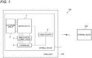
- Fig. 1 shows the functional configuration of a BMI system 100 of an embodiment.
- the BMI system 100 includes an internal device 1 and an external device 200.
- the internal device 1 is configured so as to be used while being implanted in the living body 300 (specifically, the head) .
- the external device 200 is configured so as to be used while being placed outside the living body 300.
- the internal device 1 includes an electrode group 2 including N electrodes.
- N is an integer of 2 or more.
- Each of the electrodes of the electrode group 2 is configured so as to be attached to a predetermined place of the brain of the living body 300, and acquire an electroencephalogram signal in the place.
- the internal device 1 further includes: an amplification element group 3 including N amplification elements; and a matrix switch 4.
- the amplification element group 3 is electrically connected to the electrode group 2 through the matrix switch 4.
- Each of the amplification elements of the amplification element group 3 is configured so as to amplify an input signal, and output the amplified signal.
- the internal device 1 further includes a communicator 5.
- the communicator 5 is electrically connected to output terminals of the amplification element group 3.
- the communicator 5 is configured so as to be able to wirelessly communicate with the external device 200.
- the internal device 1 further includes a controller 6.
- the controller 6 is configured so as to operate the matrix switch 4 to control the electrical connection state between the electrode group 2 and the amplification element group 3.
- the controller 6 is also configured so as to be able to control the operation of the communicator 5.
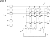
- Fig. 2 specifically shows the circuit configuration of a part of the internal device 1.
- the electrode group 2 includes N electrodes 21, 22, 23, ..., 2N.
- the amplification element group 3 includes N amplification elements 31, 32, 33, ..., 3N.
- the matrix switch 4 includes an N x N number of switch elements. Each of the switch elements is electrically connected to the controller 6 through a signal line which is not shown. Therefore, the controller 6 can control the opening/closing operation of each of the switch elements.
- the matrix switch includes switch elements 411, 412, 413, ..., 41N.
- the input ends of the switch elements 411, 412, 413, ..., 41N are electrically connected to the electrode 21.
- the matrix switch further includes switch elements 421, 422, 423, ..., 42N.
- the input ends of the switch elements 421, 422, 423, ..., 42N are electrically connected to the electrode 22.
- the matrix switch further includes switch elements 431, 432, 433, ..., 43N.
- the input ends of the switch elements 431, 432, 433, ..., 43N are electrically connected to the electrode 23.
- the matrix switch further includes switch elements 4N1, 4N2, 4N3, ..., 4NN.
- the input ends of the switch elements 4N1, 4N2, 4N3, ..., 4NN are electrically connected to the electrode 2N.
- the output ends of the switch elements 411, 421, 431, ..., 4N1 are electrically output to the amplification element 31.
- the switch element 4N1 is closed, for example, the electroencephalogram signal which is acquired by the electrode 2N is supplied to the amplification element 31.
- the output ends of the switch elements 412, 422, 432, ..., 4N2 are electrically output to the amplification element 32.
- the switch element 432 is closed, for example, the electroencephalogram signal which is acquired by the electrode 23 is supplied to the amplification element 32.
- the output ends of the switch elements 413, 423, 433, ..., 4N3 are electrically output to the amplification element 33.
- the switch element 423 is closed, for example, the electroencephalogram signal which is acquired by the electrode 22 is supplied to the amplification element 33.
- the output ends of the switch elements 41N, 42N, 43N, ..., 4NN are electrically output to the amplification element 3N.
- the switch element 41N is closed, for example, the electroencephalogram signal which is acquired by the electrode 21 is supplied to the amplification element 3N.
- the electrode group 2 further includes an electrode 2R.
- the electroencephalogram signal which is acquired through the electrode 2R is supplied as a reference potential signal to the amplification elements 31, 32, 33, ..., 3N, respectively. Namely, the electrode 2R is used as the reference potential supply source.
- Each of the amplification elements 31, 32, 33, ..., 3N is configured so as to amplify the difference between the input electroencephalogram signal and the reference potential signal, by a predetermined amplification factor, and output the amplified signal.
- the amplified electroencephalogram signals which are output respectively from the amplification elements 31, 32, 33, ..., 3N are supplied to the controller 6.
- the controller 6 is configured so as to selectively execute one of a normal operation mode and a noise-reduction operation mode.
- Fig. 3 shows a configuration example of the matrix switch 4 during execution of the normal operation mode
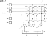
- Fig. 4 shows a configuration example of the matrix switch 4 during execution of the noise-reduction operation mode.
- the controller 6 causes the electroencephalogram signals of the living body 300 which are acquired through the N electrodes of the electrode group 2, to the N amplification elements of the amplification element group 3, in such a manner that each of the electrodes corresponds to a respective one of the amplification elements.
- the controller 6 controls the matrix switch 4 so that the switch elements 411, 422, 433, ..., 4NN are closed. Therefore, the electroencephalogram signal acquired through the electrode 21 is supplied to the amplification element 31. Similarly, the electroencephalogram signal acquired through the electrode 22 is supplied to the amplification element 32, that acquired through the electrode 23 is supplied to the amplification element 33, and that acquired through the electrode 2N is supplied to the amplification element 3N.
- the N amplified electroencephalogram signals which are output from the amplification elements 31, 32, 33, ..., 3N are supplied to the controller 6.
- the controller 6 relays directly the N amplified electroencephalogram signals which are input thereto, to the communicator 5. Thereafter, the controller 6 causes the communicator 5 to wirelessly transmit the N amplified electroencephalogram signals at a predetermined timing.
- the amplified electroencephalogram signals which are wirelessly transmitted are received by the external device 200 .
- the external device 200 operates in accordance with the received and amplified electroencephalogram signals.
- the external device 200 may be identical with or different from a device which receives the signals transmitted from the internal device 1, and which executes an operation based on the signals.
- the external device 200 may be a device which receives the signals transmitted from the internal device 1, and which transmits a control signal that causes another external device to execute the operation based on the transmitted signals.
- the controller 6 causes the electroencephalogram signals of the living body 300 which are acquired through an M number of electrodes (M is smaller than N) of the electrode group 2, to be supplied to the amplification element group 3 in such a manner that each electrode corresponds to respective plural ones of the amplification elements.
- the controller 6 controls the matrix switch 4 so that the switch elements 411, 412, 433, ..., 43N are closed. Therefore, the electroencephalogram signal acquired through the electrode 21 is supplied in parallel to the amplification elements 31, 32. Similarly, the electroencephalogram signal acquired through the electrode 23 is supplied in parallel to the amplification element group including the amplification elements 33, 3N. In this example, namely, M is 2.
- the controller 6 performs a process of arithmetically averaging the amplified electroencephalogram signals which are output from the plurality of amplification elements that correspond to each of the M electrodes.
- the amplified electroencephalogram signals which are output from the amplification elements 31, 32 that correspond to the electrode 21 are arithmetically averaged.
- the amplified electroencephalogram signals which are output from the amplification elements 33, 3N that correspond to the electrode 23 are arithmetically averaged.
- the controller 6 acquires M (in the example, M is 2) arithmetically averaged and amplified electroencephalogram signals.
- the noise level of the obtained signal is reduced to 1/ ⁇ n as compared to that of the signal which has not been arithmetically averaged.
- the noise level can be reduced to 1/ ⁇ 2 by arithmetically averaging the amplified electroencephalogram signals which are output from the amplification elements 31, 32.
- the noise level can be reduced to 1/ ⁇ m by arithmetically averaging amplified electroencephalogram signals output from the amplification element group.
- the controller 6 relays the M amplified electroencephalogram signals in which the noise level is reduced, to the communicator 5. Thereafter, the controller 6 causes the communicator 5 to wirelessly transmit the M amplified electroencephalogram signals at a predetermined timing.
- the amplified electroencephalogram signals which are wirelessly transmitted are received by the external device 200.
- the external device 200 operates in accordance with the received and amplified electroencephalogram signals.
- the living body 300 is a patient in whom brain waves diminish with progression of disease.
- An example of disease is ALS.
- the internal device 1 is implanted in the head of the patient in a stage where communication with the patient can be well performed.
- the controller 6 first executes the normal operation mode.
- the normal operation mode electroencephalogram signals of the patient are acquired by using the electrode group 2 including as many (N) electrodes as possible, and therefore also the number of channels for the amplified electroencephalogram signals which are supplied to the external device 200 through the communicator 5 is maximum. Consequently, a rapid BMI control having a high degree of freedom can be performed.
- the controller 6 executes the noise-reduction operation mode.
- M electrodes which are to continue to acquire electroencephalogram signals are selected from the N electrodes of the electrode group 2.
- the M electrodes are selected as an electrode group with higher priority to perform a significant BMI control.
- the selected M electrodes may be varied depending on the patient.
- a signal designating the selected M electrodes iswirelessly transmitted from the external device 200, and then received by the communicator 5. Based on the signal received by the communicator 5, the controller 6 operates the matrix switch 4.
- Each of M electroencephalogram signals in which the SN ratio is lowered is supplied to a plurality of amplification elements.
- the amplified electroencephalogram signals which are output from the plurality of amplification elements are arithmetically averaged.
- M amplified electroencephalogram signals in which the noise level is lowered as compared with the case of the normal operation mode are obtained.
- the number of used electrodes, i.e., the channel number is reduced, and therefore it is unavoidable that the degree of freedom of the BMI control is lowered.
- small changes, which, in the related art, are buried in noise can be distinguished. Even with respect to a patient in whom the intensity of brain waves is reduced with progression of disease, therefore, the possibility of the BMI control can be provided for a long period of time.
- the function of the controller 6 is realized from software executed by a cooperation of a processor and memory which are communicably connected to each other.
- the processor are a CPU and an MPU.
- the memory are a RAM and a ROM.
- the function of the controller 6 may be realized by hardware such as an ASIC or an FPGA, or a combination of hardware and software.
- the electroencephalogram signal acquired by the electrode 2R is supplied as the reference potential signal to each of the amplification elements of the amplification element group 3.
- a configuration may be employed in which, as shown in Fig. 5 , one of two electrodes 2R1, 2R2 (an example of the plurality of reference potential supply sources) is electrically connected to the amplification element group 3 in a switchable manner.
- the number of switchable electrodes may be 3 or more.
- the internal device 1 is used while being implanted in the living body 300, and therefore cannot be easily taken out from the body after the operation is started. According to the configuration, even when any failure occurs in the electrode 2R1 which is originally used as the reference potential supply source, the reference potential supply source can be switched to the other electrode 2R2, so that the amplification element group 3 can continue to operate. Therefore, the number of opportunities of exchanging the internal device 1 which impose a burden on the patient can be reduced, and the possibility of the BMI control can be provided for a long period of time.
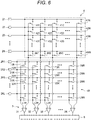
- a configuration may be employed that, as shown in Fig. 6 , includes a matrix switch 4R in which the above-described function of switching between the electrodes 2R1, 2R2 is more generalized.
- the matrix switch 4R includes L x N switch elements (11R, 12R, ..., LNR).
- L is an integer of N or less.
- the electrode group 2 includes L electrodes 2R1, 2R2, 2R3, ..., 2RL.
- the electroencephalogram signal acquired by one of the electrodes 21 to 2N, and the reference potential or differential input acquired by one of the electrodes 2R1 to 2RL can be supplied to any one of the amplification elements 31 to 3N.
- a switch signal is wirelessly transmitted from the external device 200, and then received by the communicator 5. Based on the received signal, the switching of the reference potential supply sources can be performed by the controller 6. Alternatively, a configuration may be employed in which the controller 6 detects a failure of the original reference potential supply source, and then automatically performs switching of the reference potential supply sources.
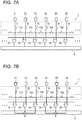
- the internal device 1 may include a ladder-type switch circuit network 7 shown in Fig. 7A .
- the electrodes 21 to 26 are shown as a part of the electrode group 2
- the amplification elements 31 to 36 are shown as a part of the amplification element group 3
- switch elements 71 to 76 and 712 to 756 are shown as a part of the ladder-type switch circuit network 7.
- the input end of the switch element 71 is connected to the electrode 21.
- the output end of the switch element 71 is connected to the amplification element 31.
- the switch element 712 can connect the output ends of the adjacent switch elements 71, 72 together.
- n is an arbitrary integer
- the input end of a switch element 7n is connected to an electrode 2n, and the output end of the switch element 7n is connected to an amplification element 3n.
- a switch element 7n(n+1) connects the output end of the switch element 7n to that of a switch element 7(n+1).
- Fig. 7B shows an example of the operation of the thus configured ladder-type switch circuit network 7.
- the switch elements 71, 712, 723 are closed, the electroencephalogram signal acquired by the electrode 21 is supplied to the amplification elements 31, 32, 33.
- the switch elements 75, 745, 756 are closed, similarly, the electroencephalogram signal acquired by the electrode 25 is supplied to the amplification elements 34, 35, 36.
- the selection of either of the normal operation mode and the noise-reduction operation mode is performed by the controller 6 based on the signal which is received from the external device 200 by the communicator 5.
- the internal device 1 can be configured so as to detect the noise levels of the electroencephalogram signals acquired by the electrode group 2. In this case, based on the detected noise levels, the controller 6 determines whether a significant BMI control can be performed in the normal operation mode or not. If it is determined that a significant BMI control cannot be performed in the normal operation mode, the controller 6 automatically selects the noise-reduction operation mode.
- electroencephalogram signals of the patient are acquired by using as many (the N number of) electrodes as possible. Therefore, also the number of channels for the amplified electroencephalogram signals which are supplied to the external device through the communicator is maximum. Consequently, a rapid BMI control having a high degree of freedom can be performed.
- the controller can execute the noise-reduction operation mode. At this time, the M number of electrodes are selected from the N electrodes.
- each of the M electroencephalogram signals in which the SN ratio is lowered is supplied to a plurality of amplification elements.
- M amplified electroencephalogram signals in which the noise level is lowered as compared with the case of the normal operation mode are obtained.
- the number of used electrodes, i.e., the channel number is reduced, and therefore it is unavoidable that the degree of freedom of the BMI control is lowered.
- small changes, which, in the related art, are buried in noise can be distinguished. Even with respect to a patient in whom the intensity of brain waves is reduced with progression of disease, therefore, the possibility of the BMI control can be provided for a long period of time.
Landscapes
- Health & Medical Sciences (AREA)
- Life Sciences & Earth Sciences (AREA)
- Engineering & Computer Science (AREA)
- General Health & Medical Sciences (AREA)
- Biomedical Technology (AREA)
- Physics & Mathematics (AREA)
- Public Health (AREA)
- Veterinary Medicine (AREA)
- Biophysics (AREA)
- Pathology (AREA)
- Heart & Thoracic Surgery (AREA)
- Medical Informatics (AREA)
- Molecular Biology (AREA)
- Surgery (AREA)
- Animal Behavior & Ethology (AREA)
- General Engineering & Computer Science (AREA)
- Neurology (AREA)
- Signal Processing (AREA)
- Theoretical Computer Science (AREA)
- Psychiatry (AREA)
- Neurosurgery (AREA)
- Physiology (AREA)
- Computer Vision & Pattern Recognition (AREA)
- Dermatology (AREA)
- Human Computer Interaction (AREA)
- General Physics & Mathematics (AREA)
- Artificial Intelligence (AREA)
- Psychology (AREA)
- Computer Networks & Wireless Communication (AREA)
- Measurement And Recording Of Electrical Phenomena And Electrical Characteristics Of The Living Body (AREA)
- Measuring And Recording Apparatus For Diagnosis (AREA)
- User Interface Of Digital Computer (AREA)
Abstract
Description
- The presently disclosed subject matter relates to a brain-machine interface (BMI) system including: an internal device which is to be implanted in the living body; and an external device which is to be placed outside the living body, particularly to the internal device and a method of controlling the internal device.
- An internal device acquires brain waves functioning as a signal source to detect the brain activity, and transmits a signal which corresponds to the brain activity, or that which is obtained by processing the signal, to an external device. The external device operates in accordance with the signal received from the internal device. The internal device disclosed in
US 2006/0049957 A1 includes a plurality of electrodes which are to be implanted in the living body to detect brain waves. - An internal device such as described above is implanted in the brain of a patient with amyotrophic lateral sclerosis (ALS) or the like, and communication with the patient is supported. In ALS, in the case of strong degeneration of upper motor neurons, however, brain waves gradually diminish. In order to adequately acquire diminished electroencephalogram signals, it is necessary to design the low-noise performance of a group of signal amplification elements which are mounted on the internal device, while anticipating the levels of the diminished electroencephalogram signals. When such a design is employed, however, the size increase of the internal device due to the scale enlargement of an amplification circuit, and heat generation due to the increase of power consumption are inevitable. Therefore, the design is not adequate for an implantable type internal device.
- The presently disclosed subject matter may provide an internal device of a brain-machine interface system and a method of controlling the internal device capable of performing the BMI control for a long period of time, even with respect to a patient in whom the intensity of brain waves is reduced with progression of disease.
- The internal device of a brain-machine interface system, adapted to be implanted in a living body, may include: an electrode group which includes N electrodes acquiring electroencephalogram signals of the living body, wherein N is 2 or more; an amplification element group which includes N amplification elements; a communicator which is configured to wirelessly communicate with an external device; and a controller which is configured to control an electrical connection between the electrode group and the amplification element group, and which is configured to control the communicator, the controller which is configured to selectively execute one of: a normal operation mode in which electroencephalogram signals of the living body that are acquired through the N electrodes of the electrode group are supplied to the amplification element group in a manner that each of the N electrodes corresponds to a respective one of the N amplification elements, and the communicator is caused to wirelessly transmit N amplified electroencephalogram signals; and a noise-reduction operation mode in which an electroencephalogram signal of the living body that is acquired through an M electrode of the electrode group is supplied to the amplification element group in a manner that each M electrode corresponds to respective plural ones of the amplification elements, and the communicator is caused to wirelessly transmit an M amplified electroencephalogram signal, wherein M is smaller than N.
-
-
Fig. 1 is a block diagram showing the functional configuration of a BMI system which is an embodiment. -
Fig. 2 is a circuit diagram showing a part of an internal device of the BMI system. -
Fig. 3 is a circuit diagram illustrating the operation of the internal device. -
Fig. 4 is a circuit diagram illustrating the operation of the internal device. -
Fig. 5 is a circuit diagram showing a modification of the internal device. -
Fig. 6 is a circuit diagram showing another modification of the internal device. -
Figs. 7A and 7B are circuit diagrams showing a further modification of the internal device. - Hereinafter, an embodiment will be described in detail with reference to the accompanying drawings.
-
Fig. 1 shows the functional configuration of aBMI system 100 of an embodiment. TheBMI system 100 includes aninternal device 1 and anexternal device 200. Theinternal device 1 is configured so as to be used while being implanted in the living body 300 (specifically, the head) . Theexternal device 200 is configured so as to be used while being placed outside theliving body 300. - The
internal device 1 includes anelectrode group 2 including N electrodes. In the following description, N is an integer of 2 or more. Each of the electrodes of theelectrode group 2 is configured so as to be attached to a predetermined place of the brain of theliving body 300, and acquire an electroencephalogram signal in the place. - The
internal device 1 further includes: anamplification element group 3 including N amplification elements; and amatrix switch 4. Theamplification element group 3 is electrically connected to theelectrode group 2 through thematrix switch 4. Each of the amplification elements of theamplification element group 3 is configured so as to amplify an input signal, and output the amplified signal. - The
internal device 1 further includes acommunicator 5. Thecommunicator 5 is electrically connected to output terminals of theamplification element group 3. Thecommunicator 5 is configured so as to be able to wirelessly communicate with theexternal device 200. - The
internal device 1 further includes acontroller 6. Thecontroller 6 is configured so as to operate thematrix switch 4 to control the electrical connection state between theelectrode group 2 and theamplification element group 3. Thecontroller 6 is also configured so as to be able to control the operation of thecommunicator 5. -
Fig. 2 specifically shows the circuit configuration of a part of theinternal device 1. Theelectrode group 2 includesN electrodes amplification element group 3 includesN amplification elements - The
matrix switch 4 includes an N x N number of switch elements. Each of the switch elements is electrically connected to thecontroller 6 through a signal line which is not shown. Therefore, thecontroller 6 can control the opening/closing operation of each of the switch elements. - The matrix switch includes
switch elements switch elements electrode 21. - The matrix switch further includes
switch elements switch elements electrode 22. - The matrix switch further includes
switch elements switch elements electrode 23. - The matrix switch further includes switch elements 4N1, 4N2, 4N3, ..., 4NN. The input ends of the switch elements 4N1, 4N2, 4N3, ..., 4NN are electrically connected to the
electrode 2N. - The output ends of the
switch elements amplification element 31. When the switch element 4N1 is closed, for example, the electroencephalogram signal which is acquired by theelectrode 2N is supplied to theamplification element 31. - The output ends of the
switch elements amplification element 32. When theswitch element 432 is closed, for example, the electroencephalogram signal which is acquired by theelectrode 23 is supplied to theamplification element 32. - The output ends of the
switch elements amplification element 33. When theswitch element 423 is closed, for example, the electroencephalogram signal which is acquired by theelectrode 22 is supplied to theamplification element 33. - The output ends of the
switch elements amplification element 3N. When theswitch element 41N is closed, for example, the electroencephalogram signal which is acquired by theelectrode 21 is supplied to theamplification element 3N. - The
electrode group 2 further includes anelectrode 2R. The electroencephalogram signal which is acquired through theelectrode 2R is supplied as a reference potential signal to theamplification elements electrode 2R is used as the reference potential supply source. - Each of the
amplification elements amplification elements controller 6. - The
controller 6 is configured so as to selectively execute one of a normal operation mode and a noise-reduction operation mode.Fig. 3 shows a configuration example of thematrix switch 4 during execution of the normal operation mode, andFig. 4 shows a configuration example of thematrix switch 4 during execution of the noise-reduction operation mode. - When the normal operation mode is executed, the
controller 6 causes the electroencephalogram signals of the livingbody 300 which are acquired through the N electrodes of theelectrode group 2, to the N amplification elements of theamplification element group 3, in such a manner that each of the electrodes corresponds to a respective one of the amplification elements. - As shown in
Fig. 3 , for example, thecontroller 6 controls thematrix switch 4 so that theswitch elements electrode 21 is supplied to theamplification element 31. Similarly, the electroencephalogram signal acquired through theelectrode 22 is supplied to theamplification element 32, that acquired through theelectrode 23 is supplied to theamplification element 33, and that acquired through theelectrode 2N is supplied to theamplification element 3N. - As a result, the N amplified electroencephalogram signals which are output from the
amplification elements controller 6. Thecontroller 6 relays directly the N amplified electroencephalogram signals which are input thereto, to thecommunicator 5. Thereafter, thecontroller 6 causes thecommunicator 5 to wirelessly transmit the N amplified electroencephalogram signals at a predetermined timing. The amplified electroencephalogram signals which are wirelessly transmitted are received by theexternal device 200 . Theexternal device 200 operates in accordance with the received and amplified electroencephalogram signals. - The
external device 200 may be identical with or different from a device which receives the signals transmitted from theinternal device 1, and which executes an operation based on the signals. For example, theexternal device 200 may be a device which receives the signals transmitted from theinternal device 1, and which transmits a control signal that causes another external device to execute the operation based on the transmitted signals. - When the noise-reduction operation mode is executed, the
controller 6 causes the electroencephalogram signals of the livingbody 300 which are acquired through an M number of electrodes (M is smaller than N) of theelectrode group 2, to be supplied to theamplification element group 3 in such a manner that each electrode corresponds to respective plural ones of the amplification elements. - As shown in
Fig. 4 , for example, thecontroller 6 controls thematrix switch 4 so that theswitch elements electrode 21 is supplied in parallel to theamplification elements electrode 23 is supplied in parallel to the amplification element group including theamplification elements - Next, the
controller 6 performs a process of arithmetically averaging the amplified electroencephalogram signals which are output from the plurality of amplification elements that correspond to each of the M electrodes. In this example, the amplified electroencephalogram signals which are output from theamplification elements electrode 21 are arithmetically averaged. Similarly, the amplified electroencephalogram signals which are output from theamplification elements electrode 23 are arithmetically averaged. As a result, thecontroller 6 acquires M (in the example, M is 2) arithmetically averaged and amplified electroencephalogram signals. - It is known that, when a signal with noises is supplied to n amplification elements, and the n amplified signal which are output from the n amplification elements are arithmetically averaged, the noise level of the obtained signal is reduced to 1/√n as compared to that of the signal which has not been arithmetically averaged. In this example, therefore, the noise level can be reduced to 1/√2 by arithmetically averaging the amplified electroencephalogram signals which are output from the
amplification elements amplification elements - The
controller 6 relays the M amplified electroencephalogram signals in which the noise level is reduced, to thecommunicator 5. Thereafter, thecontroller 6 causes thecommunicator 5 to wirelessly transmit the M amplified electroencephalogram signals at a predetermined timing. The amplified electroencephalogram signals which are wirelessly transmitted are received by theexternal device 200. Theexternal device 200 operates in accordance with the received and amplified electroencephalogram signals. - Next, a method of operating the thus configured
internal device 1 will be described. It is assumed that the livingbody 300 is a patient in whom brain waves diminish with progression of disease. An example of disease is ALS. Theinternal device 1 is implanted in the head of the patient in a stage where communication with the patient can be well performed. - The
controller 6 first executes the normal operation mode. In the normal operation mode, electroencephalogram signals of the patient are acquired by using theelectrode group 2 including as many (N) electrodes as possible, and therefore also the number of channels for the amplified electroencephalogram signals which are supplied to theexternal device 200 through thecommunicator 5 is maximum. Consequently, a rapid BMI control having a high degree of freedom can be performed. - With progression of disease, the brain waves of the patient diminish, and the SN ratios of the acquired electroencephalogram signals are lowered. When it is determined that it is difficult to perform a significant BMI control based on the brain waves which are acquired in the normal operation mode, the
controller 6 executes the noise-reduction operation mode. - Specifically, M electrodes which are to continue to acquire electroencephalogram signals are selected from the N electrodes of the
electrode group 2. Through observation of the BMI control performed in the normal operation mode, the M electrodes are selected as an electrode group with higher priority to perform a significant BMI control. The selected M electrodes may be varied depending on the patient. A signal designating the selected M electrodes iswirelessly transmitted from theexternal device 200, and then received by thecommunicator 5. Based on the signal received by thecommunicator 5, thecontroller 6 operates thematrix switch 4. - Each of M electroencephalogram signals in which the SN ratio is lowered is supplied to a plurality of amplification elements. The amplified electroencephalogram signals which are output from the plurality of amplification elements are arithmetically averaged. As a result, M amplified electroencephalogram signals in which the noise level is lowered as compared with the case of the normal operation mode are obtained. The number of used electrodes, i.e., the channel number is reduced, and therefore it is unavoidable that the degree of freedom of the BMI control is lowered. In brain waves of the patient, however, small changes, which, in the related art, are buried in noise can be distinguished. Even with respect to a patient in whom the intensity of brain waves is reduced with progression of disease, therefore, the possibility of the BMI control can be provided for a long period of time.
- In the embodiment, the function of the
controller 6 is realized from software executed by a cooperation of a processor and memory which are communicably connected to each other. Examples of the processor are a CPU and an MPU. Examples of the memory are a RAM and a ROM. However, the function of thecontroller 6 may be realized by hardware such as an ASIC or an FPGA, or a combination of hardware and software. - The above-described embodiment is a mere example for facilitating understanding of the presently disclosed subject matter. The configuration of the embodiment may be adequately changed or improved without departing the spirit of the presently disclosed subject matter. It is obvious that equivalents are included within the technical scope of the presently disclosed subject matter.
- In the above-described embodiment, the electroencephalogram signal acquired by the
electrode 2R is supplied as the reference potential signal to each of the amplification elements of theamplification element group 3. Alternatively, a configuration may be employed in which, as shown inFig. 5 , one of two electrodes 2R1, 2R2 (an example of the plurality of reference potential supply sources) is electrically connected to theamplification element group 3 in a switchable manner. The number of switchable electrodes may be 3 or more. - The
internal device 1 is used while being implanted in the livingbody 300, and therefore cannot be easily taken out from the body after the operation is started. According to the configuration, even when any failure occurs in the electrode 2R1 which is originally used as the reference potential supply source, the reference potential supply source can be switched to the other electrode 2R2, so that theamplification element group 3 can continue to operate. Therefore, the number of opportunities of exchanging theinternal device 1 which impose a burden on the patient can be reduced, and the possibility of the BMI control can be provided for a long period of time. - A configuration may be employed that, as shown in
Fig. 6 , includes amatrix switch 4R in which the above-described function of switching between the electrodes 2R1, 2R2 is more generalized. Thematrix switch 4R includes L x N switch elements (11R, 12R, ..., LNR). Here, L is an integer of N or less. Theelectrode group 2 includes L electrodes 2R1, 2R2, 2R3, ..., 2RL. - When all switch elements in which the input end is connected to one of the electrodes 2R1 to 2RL (for example, the
switch elements 31R to 3NR connected to the electrode 2R3) are closed, the potential which is supplied through the electrode 2R3 is supplied as the reference potential or a differential input to theamplification elements 31 to 3N. - When switch elements which are arbitrarily selected from the
switch elements 411 to 4NN included in thematrix switch 4, and theswitch elements 11R to LNR included in thematrix switch 4R are closed, alternatively, the electroencephalogram signal acquired by one of theelectrodes 21 to 2N, and the reference potential or differential input acquired by one of the electrodes 2R1 to 2RL can be supplied to any one of theamplification elements 31 to 3N. - A switch signal is wirelessly transmitted from the
external device 200, and then received by thecommunicator 5. Based on the received signal, the switching of the reference potential supply sources can be performed by thecontroller 6. Alternatively, a configuration may be employed in which thecontroller 6 detects a failure of the original reference potential supply source, and then automatically performs switching of the reference potential supply sources. - In place of the
matrix switch 4 in the above-described embodiment, theinternal device 1 may include a ladder-typeswitch circuit network 7 shown inFig. 7A . In the example, theelectrodes 21 to 26 are shown as a part of theelectrode group 2, theamplification elements 31 to 36 are shown as a part of theamplification element group 3, and switchelements 71 to 76 and 712 to 756 are shown as a part of the ladder-typeswitch circuit network 7. - The input end of the
switch element 71 is connected to theelectrode 21. The output end of theswitch element 71 is connected to theamplification element 31. Theswitch element 712 can connect the output ends of theadjacent switch elements -
Fig. 7B shows an example of the operation of the thus configured ladder-typeswitch circuit network 7. When theswitch elements electrode 21 is supplied to theamplification elements switch elements electrode 25 is supplied to theamplification elements - In the above-described embodiment, the selection of either of the normal operation mode and the noise-reduction operation mode is performed by the
controller 6 based on the signal which is received from theexternal device 200 by thecommunicator 5. However, theinternal device 1 can be configured so as to detect the noise levels of the electroencephalogram signals acquired by theelectrode group 2. In this case, based on the detected noise levels, thecontroller 6 determines whether a significant BMI control can be performed in the normal operation mode or not. If it is determined that a significant BMI control cannot be performed in the normal operation mode, thecontroller 6 automatically selects the noise-reduction operation mode. - According to an aspect of the presently disclosed subject matter, in the normal operation mode, electroencephalogram signals of the patient are acquired by using as many (the N number of) electrodes as possible. Therefore, also the number of channels for the amplified electroencephalogram signals which are supplied to the external device through the communicator is maximum. Consequently, a rapid BMI control having a high degree of freedom can be performed.
- In the case of a patient in whom brain waves diminish with progression of disease, the SN ratio of an acquired electroencephalogram signal is lowered with the progression of the disease. Upon a timing when it is difficult to perform a significant BMI control based on electroencephalogram signals which are acquired in the normal operation mode, the controller can execute the noise-reduction operation mode. At this time, the M number of electrodes are selected from the N electrodes.
- In the noise-reduction operation mode, each of the M electroencephalogram signals in which the SN ratio is lowered is supplied to a plurality of amplification elements. As a result, M amplified electroencephalogram signals in which the noise level is lowered as compared with the case of the normal operation mode are obtained. The number of used electrodes, i.e., the channel number is reduced, and therefore it is unavoidable that the degree of freedom of the BMI control is lowered. In brain waves of the patient, however, small changes, which, in the related art, are buried in noise can be distinguished. Even with respect to a patient in whom the intensity of brain waves is reduced with progression of disease, therefore, the possibility of the BMI control can be provided for a long period of time.
Claims (10)
- An internal device of a brain-machine interface system, the internal device adapted to be implanted in a living body, the internal device comprising:an electrode group which includes N electrodes acquiring electroencephalogram signals of the living body, wherein N is 2 or more;an amplification element group which includes N amplification elements;a communicator which is configured to wirelessly communicate with an external device; anda controller which is configured to control an electrical connection between the electrode group and the amplification element group, and which is configured to control the communicator, the controller which is configured to selectively execute one of:a normal operation mode in which electroencephalogram signals of the living body that are acquired through the N electrodes of the electrode group are supplied to the amplification element group in a manner that each of the N electrodes corresponds to a respective one of the N amplification elements, and the communicator is caused to wirelessly transmit N amplified electroencephalogram signals; anda noise-reduction operation mode in which an electroencephalogram signal of the living body that is acquired through an M electrode of the electrode group is supplied to the amplification element group in a manner that each M electrode corresponds to respective plural ones of the amplification elements, and the communicator is caused to wirelessly transmit an M amplified electroencephalogram signal, wherein M is smaller than N.
- The internal device according to claim 1, wherein
the controller is configured to arithmetically average outputs of the amplification elements to acquire the M amplified electroencephalogram signal. - The internal device according to claim 1 or 2, further comprising: a plurality of reference potential supply sources, wherein
the controller is configured to cause one of the reference potential supply sources to be electrically connected to the amplification element group in a switchable manner. - The internal device according to any one of claims 1 to 3, wherein,
based on a signal which is received from the external device by the communicator, the controller is configured to execute selection of one of the normal operation mode and the noise-reduction operation mode. - The internal device according to any one of claims 1 to 3, wherein,
based on noise levels of the acquired electroencephalogram signals, the controller is configured to automatically execute selection of one of the normal operation mode and the noise-reduction operation mode. - A method of controlling an internal device of a brain-machine interface system, the internal device adapted to be implanted in a living body, the method comprising:by a controller of the internal device, selectively executing one of:a normal operation mode in which electroencephalogram signals of the living body that are acquired through N electrodes of an electrode group are supplied to an amplification element group in a manner that each of the N electrodes corresponds to a respective one of N amplification elements of the amplification element group, and N amplified electroencephalogram signals are output, wherein N is 2 or more; anda noise-reduction operation mode in which an electroencephalogram signal of the living body that is acquired through an M electrode of the electrode group is supplied to the amplification element group in a manner that each M electrode corresponds to respective plural ones of the amplification elements of the amplification element group, and an M amplified electroencephalogram signal is output, wherein M is smaller than N.
- The method according to claim 6, wherein
outputs of the amplification elements are arithmetically averaged by the controller to acquire the M amplified electroencephalogram signal. - The method according to claim 6 or 7, further comprising:by the controller, electrically connecting one of a plurality of reference potential supply sources to the amplification element group in a switchable manner.
- The method according to any one of claims 6 to 8, wherein
the selection of one of the normal operation mode and the noise-reduction operation mode is executed by the controller based on a signal which is wirelessly transmitted from an external device. - The method according to any one of claims 6 to 8, wherein
the selection of one of the normal operation mode and the noise-reduction operation mode is executed by the controller based on noise levels of the acquired electroencephalogram signals.
Applications Claiming Priority (1)
| Application Number | Priority Date | Filing Date | Title |
|---|---|---|---|
| JP2016215375A JP6867565B2 (en) | 2016-11-02 | 2016-11-02 | Brain-machine interface system with noise reduction method and its control method |
Publications (2)
| Publication Number | Publication Date |
|---|---|
| EP3318186A1 true EP3318186A1 (en) | 2018-05-09 |
| EP3318186B1 EP3318186B1 (en) | 2021-05-12 |
Family
ID=60244931
Family Applications (1)
| Application Number | Title | Priority Date | Filing Date |
|---|---|---|---|
| EP17199656.4A Active EP3318186B1 (en) | 2016-11-02 | 2017-11-02 | An internal device of brain-machine interface system including noise reduction technique, and method of controlling the internal device |
Country Status (3)
| Country | Link |
|---|---|
| US (1) | US10620702B2 (en) |
| EP (1) | EP3318186B1 (en) |
| JP (1) | JP6867565B2 (en) |
Families Citing this family (6)
| Publication number | Priority date | Publication date | Assignee | Title |
|---|---|---|---|---|
| US11472579B2 (en) | 2018-12-04 | 2022-10-18 | Gpcp Ip Holdings Llc | Film securing apparatus and method |
| CN110850978A (en) * | 2019-11-06 | 2020-02-28 | 中国科学院自动化研究所 | Fully implantable brain-computer interface system |
| KR102149615B1 (en) * | 2019-11-13 | 2020-08-28 | 가톨릭관동대학교산학협력단 | Brain-machine interface learning system and method thereof |
| JP7054967B2 (en) | 2019-12-26 | 2022-04-15 | 国立大学法人大阪大学 | Resistance device, integrated circuit device, implantable device, and correction coefficient determination method |
| EP4111294A4 (en) | 2020-04-01 | 2024-03-20 | Synchron Australia Pty Ltd | SYSTEMS AND METHODS FOR CONTROLLING A DEVICE USING CHANGES DETECTED IN A SIGNAL INHERENT TO THE NEURAL SYSTEM |
| JP7455315B1 (en) | 2022-10-11 | 2024-03-26 | 株式会社JiMED | Program, manufacturing method, manufacturing equipment and connection method |
Citations (6)
| Publication number | Priority date | Publication date | Assignee | Title |
|---|---|---|---|---|
| US2920281A (en) * | 1954-04-27 | 1960-01-05 | Lenkurt Electric Co Inc | Noise suppressor |
| US4300101A (en) * | 1980-01-03 | 1981-11-10 | Nancy Flowers | Multiple parallel input noise reduction system |
| US6463322B1 (en) * | 2001-04-10 | 2002-10-08 | Viasys Healthcare, Inc. | Combination referential and differential amplifier for medical signal monitoring |
| US20060049957A1 (en) | 2004-08-13 | 2006-03-09 | Surgenor Timothy R | Biological interface systems with controlled device selector and related methods |
| US20080021514A1 (en) * | 2006-07-21 | 2008-01-24 | Pless Benjamin D | Treatment and warning of recurring therapy and other events using an implantable device |
| US20160278713A1 (en) * | 2015-03-25 | 2016-09-29 | Ecole Polytechnique Federale De Lausanne (Epfl) | Compact low-power recording architecture for multichannel acquisition of biological signals and method for compressing said biological signal data |
Family Cites Families (5)
| Publication number | Priority date | Publication date | Assignee | Title |
|---|---|---|---|---|
| JPS59177024A (en) * | 1983-12-26 | 1984-10-06 | 日本光電工業株式会社 | Body signal measuring apparatus |
| JPH0821821B2 (en) * | 1991-10-30 | 1996-03-04 | 株式会社エヌエフ回路設計ブロック | amplifier |
| US7187968B2 (en) * | 2003-10-23 | 2007-03-06 | Duke University | Apparatus for acquiring and transmitting neural signals and related methods |
| JP4289413B2 (en) * | 2007-03-26 | 2009-07-01 | 株式会社デンソー | Biological information measuring device |
| US11071499B2 (en) * | 2016-05-17 | 2021-07-27 | Case Western Reserve University | Multichannel ultra-low noise amplifier |
-
2016
- 2016-11-02 JP JP2016215375A patent/JP6867565B2/en active Active
-
2017
- 2017-11-01 US US15/800,613 patent/US10620702B2/en active Active
- 2017-11-02 EP EP17199656.4A patent/EP3318186B1/en active Active
Patent Citations (6)
| Publication number | Priority date | Publication date | Assignee | Title |
|---|---|---|---|---|
| US2920281A (en) * | 1954-04-27 | 1960-01-05 | Lenkurt Electric Co Inc | Noise suppressor |
| US4300101A (en) * | 1980-01-03 | 1981-11-10 | Nancy Flowers | Multiple parallel input noise reduction system |
| US6463322B1 (en) * | 2001-04-10 | 2002-10-08 | Viasys Healthcare, Inc. | Combination referential and differential amplifier for medical signal monitoring |
| US20060049957A1 (en) | 2004-08-13 | 2006-03-09 | Surgenor Timothy R | Biological interface systems with controlled device selector and related methods |
| US20080021514A1 (en) * | 2006-07-21 | 2008-01-24 | Pless Benjamin D | Treatment and warning of recurring therapy and other events using an implantable device |
| US20160278713A1 (en) * | 2015-03-25 | 2016-09-29 | Ecole Polytechnique Federale De Lausanne (Epfl) | Compact low-power recording architecture for multichannel acquisition of biological signals and method for compressing said biological signal data |
Also Published As
| Publication number | Publication date |
|---|---|
| US20180120937A1 (en) | 2018-05-03 |
| EP3318186B1 (en) | 2021-05-12 |
| JP6867565B2 (en) | 2021-04-28 |
| JP2018068886A (en) | 2018-05-10 |
| US10620702B2 (en) | 2020-04-14 |
Similar Documents
| Publication | Publication Date | Title |
|---|---|---|
| EP3318186B1 (en) | An internal device of brain-machine interface system including noise reduction technique, and method of controlling the internal device | |
| US10016144B2 (en) | Biological signal acquisition device and method for acquiring biological signal | |
| JP5131016B2 (en) | Wireless communication apparatus and communication control method | |
| US10524046B2 (en) | Systems and methods for automatic speech recognition | |
| EP2848994A1 (en) | Accessory, camera body | |
| CN110974210B (en) | Impedance correction method and device for physiological signal acquisition channel | |
| EP3582069B1 (en) | Brain-machine interface system capable of changing amount of communication data from internal device, and control method therefor | |
| CN113995403A (en) | Wearing state detection method, device, system, storage medium and electronic device | |
| KR102842946B1 (en) | System for driving led lamp of vehicle and method thereof | |
| KR20160136380A (en) | Near-field communication system and terminal | |
| JP2009045179A (en) | Biological information communication device and biological information monitoring system | |
| US20150223278A1 (en) | System and Method for Establishing a Wireless Connection | |
| KR102032020B1 (en) | System for diagnosing insulation elemets in bms | |
| US20050195785A1 (en) | Image signal processing device | |
| KR102023362B1 (en) | External force detecting system and driving method thereof | |
| CN119136122A (en) | Hearing device debugging method, system, device and storage medium | |
| CN116058769A (en) | Endoscope body state detection method and device for endoscope, endoscope and storage medium | |
| JP4684917B2 (en) | Electronic control unit | |
| US10627798B2 (en) | FPGA functionality mode switch-over | |
| EP2945697A1 (en) | Sound processor apparatus with dual-mode earhook interface assembly | |
| KR20210086761A (en) | Method for managing agricultural machine and electronic device thereof | |
| KR102277032B1 (en) | Spectrum Analyzer Having a Capability of Selectively Measuring an Antenna Signal | |
| JP2006064488A (en) | Semiconductor test equipment | |
| US11684772B2 (en) | Electrode and method for transcranial current stimulation | |
| US20160232011A1 (en) | Communication module, communication device capable of self-detecting operation status and detecting method thereof |
Legal Events
| Date | Code | Title | Description |
|---|---|---|---|
| PUAI | Public reference made under article 153(3) epc to a published international application that has entered the european phase |
Free format text: ORIGINAL CODE: 0009012 |
|
| STAA | Information on the status of an ep patent application or granted ep patent |
Free format text: STATUS: THE APPLICATION HAS BEEN PUBLISHED |
|
| AK | Designated contracting states |
Kind code of ref document: A1 Designated state(s): AL AT BE BG CH CY CZ DE DK EE ES FI FR GB GR HR HU IE IS IT LI LT LU LV MC MK MT NL NO PL PT RO RS SE SI SK SM TR |
|
| AX | Request for extension of the european patent |
Extension state: BA ME |
|
| STAA | Information on the status of an ep patent application or granted ep patent |
Free format text: STATUS: REQUEST FOR EXAMINATION WAS MADE |
|
| 17P | Request for examination filed |
Effective date: 20180629 |
|
| RBV | Designated contracting states (corrected) |
Designated state(s): AL AT BE BG CH CY CZ DE DK EE ES FI FR GB GR HR HU IE IS IT LI LT LU LV MC MK MT NL NO PL PT RO RS SE SI SK SM TR |
|
| GRAP | Despatch of communication of intention to grant a patent |
Free format text: ORIGINAL CODE: EPIDOSNIGR1 |
|
| STAA | Information on the status of an ep patent application or granted ep patent |
Free format text: STATUS: GRANT OF PATENT IS INTENDED |
|
| INTG | Intention to grant announced |
Effective date: 20201126 |
|
| GRAS | Grant fee paid |
Free format text: ORIGINAL CODE: EPIDOSNIGR3 |
|
| GRAA | (expected) grant |
Free format text: ORIGINAL CODE: 0009210 |
|
| STAA | Information on the status of an ep patent application or granted ep patent |
Free format text: STATUS: THE PATENT HAS BEEN GRANTED |
|
| AK | Designated contracting states |
Kind code of ref document: B1 Designated state(s): AL AT BE BG CH CY CZ DE DK EE ES FI FR GB GR HR HU IE IS IT LI LT LU LV MC MK MT NL NO PL PT RO RS SE SI SK SM TR |
|
| RAP1 | Party data changed (applicant data changed or rights of an application transferred) |
Owner name: JIMED INC. Owner name: OSAKA UNIVERSITY Owner name: NATIONAL INSTITUTE OF INFORMATION AND COMMUNICATIONS TECHNOLOGY |
|
| REG | Reference to a national code |
Ref country code: GB Ref legal event code: FG4D |
|
| REG | Reference to a national code |
Ref country code: CH Ref legal event code: EP |
|
| REG | Reference to a national code |
Ref country code: DE Ref legal event code: R096 Ref document number: 602017038448 Country of ref document: DE |
|
| REG | Reference to a national code |
Ref country code: IE Ref legal event code: FG4D |
|
| REG | Reference to a national code |
Ref country code: AT Ref legal event code: REF Ref document number: 1391618 Country of ref document: AT Kind code of ref document: T Effective date: 20210615 |
|
| REG | Reference to a national code |
Ref country code: NL Ref legal event code: FP |
|
| REG | Reference to a national code |
Ref country code: LT Ref legal event code: MG9D |
|
| REG | Reference to a national code |
Ref country code: AT Ref legal event code: MK05 Ref document number: 1391618 Country of ref document: AT Kind code of ref document: T Effective date: 20210512 |
|
| PG25 | Lapsed in a contracting state [announced via postgrant information from national office to epo] |
Ref country code: FI Free format text: LAPSE BECAUSE OF FAILURE TO SUBMIT A TRANSLATION OF THE DESCRIPTION OR TO PAY THE FEE WITHIN THE PRESCRIBED TIME-LIMIT Effective date: 20210512 Ref country code: LT Free format text: LAPSE BECAUSE OF FAILURE TO SUBMIT A TRANSLATION OF THE DESCRIPTION OR TO PAY THE FEE WITHIN THE PRESCRIBED TIME-LIMIT Effective date: 20210512 Ref country code: HR Free format text: LAPSE BECAUSE OF FAILURE TO SUBMIT A TRANSLATION OF THE DESCRIPTION OR TO PAY THE FEE WITHIN THE PRESCRIBED TIME-LIMIT Effective date: 20210512 Ref country code: AT Free format text: LAPSE BECAUSE OF FAILURE TO SUBMIT A TRANSLATION OF THE DESCRIPTION OR TO PAY THE FEE WITHIN THE PRESCRIBED TIME-LIMIT Effective date: 20210512 Ref country code: BG Free format text: LAPSE BECAUSE OF FAILURE TO SUBMIT A TRANSLATION OF THE DESCRIPTION OR TO PAY THE FEE WITHIN THE PRESCRIBED TIME-LIMIT Effective date: 20210812 |
|
| PG25 | Lapsed in a contracting state [announced via postgrant information from national office to epo] |
Ref country code: IS Free format text: LAPSE BECAUSE OF FAILURE TO SUBMIT A TRANSLATION OF THE DESCRIPTION OR TO PAY THE FEE WITHIN THE PRESCRIBED TIME-LIMIT Effective date: 20210912 Ref country code: LV Free format text: LAPSE BECAUSE OF FAILURE TO SUBMIT A TRANSLATION OF THE DESCRIPTION OR TO PAY THE FEE WITHIN THE PRESCRIBED TIME-LIMIT Effective date: 20210512 Ref country code: GR Free format text: LAPSE BECAUSE OF FAILURE TO SUBMIT A TRANSLATION OF THE DESCRIPTION OR TO PAY THE FEE WITHIN THE PRESCRIBED TIME-LIMIT Effective date: 20210813 Ref country code: NO Free format text: LAPSE BECAUSE OF FAILURE TO SUBMIT A TRANSLATION OF THE DESCRIPTION OR TO PAY THE FEE WITHIN THE PRESCRIBED TIME-LIMIT Effective date: 20210812 Ref country code: PL Free format text: LAPSE BECAUSE OF FAILURE TO SUBMIT A TRANSLATION OF THE DESCRIPTION OR TO PAY THE FEE WITHIN THE PRESCRIBED TIME-LIMIT Effective date: 20210512 Ref country code: PT Free format text: LAPSE BECAUSE OF FAILURE TO SUBMIT A TRANSLATION OF THE DESCRIPTION OR TO PAY THE FEE WITHIN THE PRESCRIBED TIME-LIMIT Effective date: 20210913 Ref country code: SE Free format text: LAPSE BECAUSE OF FAILURE TO SUBMIT A TRANSLATION OF THE DESCRIPTION OR TO PAY THE FEE WITHIN THE PRESCRIBED TIME-LIMIT Effective date: 20210512 Ref country code: RS Free format text: LAPSE BECAUSE OF FAILURE TO SUBMIT A TRANSLATION OF THE DESCRIPTION OR TO PAY THE FEE WITHIN THE PRESCRIBED TIME-LIMIT Effective date: 20210512 |
|
| PG25 | Lapsed in a contracting state [announced via postgrant information from national office to epo] |
Ref country code: SK Free format text: LAPSE BECAUSE OF FAILURE TO SUBMIT A TRANSLATION OF THE DESCRIPTION OR TO PAY THE FEE WITHIN THE PRESCRIBED TIME-LIMIT Effective date: 20210512 Ref country code: SM Free format text: LAPSE BECAUSE OF FAILURE TO SUBMIT A TRANSLATION OF THE DESCRIPTION OR TO PAY THE FEE WITHIN THE PRESCRIBED TIME-LIMIT Effective date: 20210512 Ref country code: DK Free format text: LAPSE BECAUSE OF FAILURE TO SUBMIT A TRANSLATION OF THE DESCRIPTION OR TO PAY THE FEE WITHIN THE PRESCRIBED TIME-LIMIT Effective date: 20210512 Ref country code: EE Free format text: LAPSE BECAUSE OF FAILURE TO SUBMIT A TRANSLATION OF THE DESCRIPTION OR TO PAY THE FEE WITHIN THE PRESCRIBED TIME-LIMIT Effective date: 20210512 Ref country code: CZ Free format text: LAPSE BECAUSE OF FAILURE TO SUBMIT A TRANSLATION OF THE DESCRIPTION OR TO PAY THE FEE WITHIN THE PRESCRIBED TIME-LIMIT Effective date: 20210512 Ref country code: RO Free format text: LAPSE BECAUSE OF FAILURE TO SUBMIT A TRANSLATION OF THE DESCRIPTION OR TO PAY THE FEE WITHIN THE PRESCRIBED TIME-LIMIT Effective date: 20210512 Ref country code: ES Free format text: LAPSE BECAUSE OF FAILURE TO SUBMIT A TRANSLATION OF THE DESCRIPTION OR TO PAY THE FEE WITHIN THE PRESCRIBED TIME-LIMIT Effective date: 20210512 |
|
| REG | Reference to a national code |
Ref country code: DE Ref legal event code: R097 Ref document number: 602017038448 Country of ref document: DE |
|
| PLBE | No opposition filed within time limit |
Free format text: ORIGINAL CODE: 0009261 |
|
| STAA | Information on the status of an ep patent application or granted ep patent |
Free format text: STATUS: NO OPPOSITION FILED WITHIN TIME LIMIT |
|
| 26N | No opposition filed |
Effective date: 20220215 |
|
| PG25 | Lapsed in a contracting state [announced via postgrant information from national office to epo] |
Ref country code: IS Free format text: LAPSE BECAUSE OF FAILURE TO SUBMIT A TRANSLATION OF THE DESCRIPTION OR TO PAY THE FEE WITHIN THE PRESCRIBED TIME-LIMIT Effective date: 20210912 Ref country code: AL Free format text: LAPSE BECAUSE OF FAILURE TO SUBMIT A TRANSLATION OF THE DESCRIPTION OR TO PAY THE FEE WITHIN THE PRESCRIBED TIME-LIMIT Effective date: 20210512 |
|
| PG25 | Lapsed in a contracting state [announced via postgrant information from national office to epo] |
Ref country code: MC Free format text: LAPSE BECAUSE OF FAILURE TO SUBMIT A TRANSLATION OF THE DESCRIPTION OR TO PAY THE FEE WITHIN THE PRESCRIBED TIME-LIMIT Effective date: 20210512 |
|
| REG | Reference to a national code |
Ref country code: CH Ref legal event code: PL |
|
| GBPC | Gb: european patent ceased through non-payment of renewal fee |
Effective date: 20211102 |
|
| PG25 | Lapsed in a contracting state [announced via postgrant information from national office to epo] |
Ref country code: LU Free format text: LAPSE BECAUSE OF NON-PAYMENT OF DUE FEES Effective date: 20211102 Ref country code: IT Free format text: LAPSE BECAUSE OF FAILURE TO SUBMIT A TRANSLATION OF THE DESCRIPTION OR TO PAY THE FEE WITHIN THE PRESCRIBED TIME-LIMIT Effective date: 20210512 Ref country code: BE Free format text: LAPSE BECAUSE OF NON-PAYMENT OF DUE FEES Effective date: 20211130 |
|
| REG | Reference to a national code |
Ref country code: BE Ref legal event code: MM Effective date: 20211130 |
|
| PG25 | Lapsed in a contracting state [announced via postgrant information from national office to epo] |
Ref country code: IE Free format text: LAPSE BECAUSE OF NON-PAYMENT OF DUE FEES Effective date: 20211102 Ref country code: GB Free format text: LAPSE BECAUSE OF NON-PAYMENT OF DUE FEES Effective date: 20211102 |
|
| PG25 | Lapsed in a contracting state [announced via postgrant information from national office to epo] |
Ref country code: HU Free format text: LAPSE BECAUSE OF FAILURE TO SUBMIT A TRANSLATION OF THE DESCRIPTION OR TO PAY THE FEE WITHIN THE PRESCRIBED TIME-LIMIT; INVALID AB INITIO Effective date: 20171102 |
|
| PG25 | Lapsed in a contracting state [announced via postgrant information from national office to epo] |
Ref country code: CY Free format text: LAPSE BECAUSE OF FAILURE TO SUBMIT A TRANSLATION OF THE DESCRIPTION OR TO PAY THE FEE WITHIN THE PRESCRIBED TIME-LIMIT Effective date: 20210512 |
|
| PG25 | Lapsed in a contracting state [announced via postgrant information from national office to epo] |
Ref country code: LI Free format text: LAPSE BECAUSE OF NON-PAYMENT OF DUE FEES Effective date: 20220701 Ref country code: CH Free format text: LAPSE BECAUSE OF NON-PAYMENT OF DUE FEES Effective date: 20220701 |
|
| PG25 | Lapsed in a contracting state [announced via postgrant information from national office to epo] |
Ref country code: MK Free format text: LAPSE BECAUSE OF FAILURE TO SUBMIT A TRANSLATION OF THE DESCRIPTION OR TO PAY THE FEE WITHIN THE PRESCRIBED TIME-LIMIT Effective date: 20210512 |
|
| PG25 | Lapsed in a contracting state [announced via postgrant information from national office to epo] |
Ref country code: TR Free format text: LAPSE BECAUSE OF FAILURE TO SUBMIT A TRANSLATION OF THE DESCRIPTION OR TO PAY THE FEE WITHIN THE PRESCRIBED TIME-LIMIT Effective date: 20210512 |
|
| PG25 | Lapsed in a contracting state [announced via postgrant information from national office to epo] |
Ref country code: MT Free format text: LAPSE BECAUSE OF FAILURE TO SUBMIT A TRANSLATION OF THE DESCRIPTION OR TO PAY THE FEE WITHIN THE PRESCRIBED TIME-LIMIT Effective date: 20210512 |
|
| PGFP | Annual fee paid to national office [announced via postgrant information from national office to epo] |
Ref country code: NL Payment date: 20251126 Year of fee payment: 9 |
|
| PGFP | Annual fee paid to national office [announced via postgrant information from national office to epo] |
Ref country code: DE Payment date: 20251124 Year of fee payment: 9 |
|
| PGFP | Annual fee paid to national office [announced via postgrant information from national office to epo] |
Ref country code: FR Payment date: 20251127 Year of fee payment: 9 |