EP3317535B1 - Method and system for efficiency increase in an energy recovery device - Google Patents
Method and system for efficiency increase in an energy recovery device Download PDFInfo
- Publication number
- EP3317535B1 EP3317535B1 EP16741542.1A EP16741542A EP3317535B1 EP 3317535 B1 EP3317535 B1 EP 3317535B1 EP 16741542 A EP16741542 A EP 16741542A EP 3317535 B1 EP3317535 B1 EP 3317535B1
- Authority
- EP
- European Patent Office
- Prior art keywords
- core
- energy recovery
- recovery system
- fluid
- temperature
- Prior art date
- Legal status (The legal status is an assumption and is not a legal conclusion. Google has not performed a legal analysis and makes no representation as to the accuracy of the status listed.)
- Active
Links
Images

Classifications
-
- F—MECHANICAL ENGINEERING; LIGHTING; HEATING; WEAPONS; BLASTING
- F03—MACHINES OR ENGINES FOR LIQUIDS; WIND, SPRING, OR WEIGHT MOTORS; PRODUCING MECHANICAL POWER OR A REACTIVE PROPULSIVE THRUST, NOT OTHERWISE PROVIDED FOR
- F03G—SPRING, WEIGHT, INERTIA OR LIKE MOTORS; MECHANICAL-POWER PRODUCING DEVICES OR MECHANISMS, NOT OTHERWISE PROVIDED FOR OR USING ENERGY SOURCES NOT OTHERWISE PROVIDED FOR
- F03G7/00—Mechanical-power-producing mechanisms, not otherwise provided for or using energy sources not otherwise provided for
- F03G7/06—Mechanical-power-producing mechanisms, not otherwise provided for or using energy sources not otherwise provided for using expansion or contraction of bodies due to heating, cooling, moistening, drying or the like
- F03G7/061—Mechanical-power-producing mechanisms, not otherwise provided for or using energy sources not otherwise provided for using expansion or contraction of bodies due to heating, cooling, moistening, drying or the like characterised by the actuating element
- F03G7/0614—Mechanical-power-producing mechanisms, not otherwise provided for or using energy sources not otherwise provided for using expansion or contraction of bodies due to heating, cooling, moistening, drying or the like characterised by the actuating element using shape memory elements
- F03G7/06143—Wires
-
- F—MECHANICAL ENGINEERING; LIGHTING; HEATING; WEAPONS; BLASTING
- F03—MACHINES OR ENGINES FOR LIQUIDS; WIND, SPRING, OR WEIGHT MOTORS; PRODUCING MECHANICAL POWER OR A REACTIVE PROPULSIVE THRUST, NOT OTHERWISE PROVIDED FOR
- F03G—SPRING, WEIGHT, INERTIA OR LIKE MOTORS; MECHANICAL-POWER PRODUCING DEVICES OR MECHANISMS, NOT OTHERWISE PROVIDED FOR OR USING ENERGY SOURCES NOT OTHERWISE PROVIDED FOR
- F03G7/00—Mechanical-power-producing mechanisms, not otherwise provided for or using energy sources not otherwise provided for
- F03G7/06—Mechanical-power-producing mechanisms, not otherwise provided for or using energy sources not otherwise provided for using expansion or contraction of bodies due to heating, cooling, moistening, drying or the like
- F03G7/064—Mechanical-power-producing mechanisms, not otherwise provided for or using energy sources not otherwise provided for using expansion or contraction of bodies due to heating, cooling, moistening, drying or the like characterised by its use
- F03G7/0641—Motors; Energy harvesting or waste energy recovery
-
- F—MECHANICAL ENGINEERING; LIGHTING; HEATING; WEAPONS; BLASTING
- F16—ENGINEERING ELEMENTS AND UNITS; GENERAL MEASURES FOR PRODUCING AND MAINTAINING EFFECTIVE FUNCTIONING OF MACHINES OR INSTALLATIONS; THERMAL INSULATION IN GENERAL
- F16J—PISTONS; CYLINDERS; SEALINGS
- F16J1/00—Pistons; Trunk pistons; Plungers
- F16J1/09—Pistons; Trunk pistons; Plungers with means for guiding fluids
Definitions
- the present application relates to the field of energy recovery and in particular to the use of Shape-memory alloys (SMAs) or Negative Thermal Expansion materials (NTE) for same.
- SMAs Shape-memory alloys
- NTE Negative Thermal Expansion materials
- SMA Shape-memory Alloy
- Shape-memory Alloys are the copper-zinc-aluminium-nickel, copper-aluminium-nickel, and nickel-titanium (NiTi) alloys but SMAs can also be created, for example, by alloying zinc, copper, gold and iron.
- a problem with the systems disclosed is that they do not take account of the time of reaction of each core for power production such that the cycle time between heating and cooling of cores can take a long time resulting in inefficient operation. Consequently much of the energy in the working fluid is wasted between heating cycles.
- the advantage of the invention is to be able to decrease the time of reaction for the shape memory alloy.
- the invention makes use of cascading the cores to decrease the cycle time and to better utilise the available fluid stream's energy potential, besides utilising the concept for the activation of the SMA elements or wires.
- the system and the method of the invention improves the effectiveness of the heat transfer in and out of the SMA wires.
- the invention can be considered as an intelligent heat exchanger that works through the deflection harvested by the transmission.
- an additional core is provided between two operating power cores.
- the additional core is configured to provide power to at least one control auxiliary system.
- the first core is concentrically mounted within the second core and configured to act two separate cores.
- the first core comprises an alloy with a different activation temperature to the second core.
- an inlet and outlet for receiving and discharging fluid from a core to define a mixing chamber area where two fluids are present at different temperatures.
- the fluid can perform a preheating or a precooling stage of the wires.
- the first core comprises a plurality of Shape-Memory Alloy (SMA) or Negative Thermal Expansion (NTE) elongated wires.
- SMA Shape-Memory Alloy
- NTE Negative Thermal Expansion
- the plurality of wires can be referred to as a bundle.
- the second core comprises a plurality of Shape-Memory Alloy (SMA) or Negative Thermal Expansion (NTE) elongated wires.
- SMA Shape-Memory Alloy
- NTE Negative Thermal Expansion
- the plurality of wires can be referred to as a bundle.
- At least one of the cores cooperates with a piston with a dome attached to its top surface.
- the dome is preferably made of a highly conductive material.
- the dome has paths cut into its surface.
- the dome comprises a highly conductive material.
- the dome comprises a plurality of channels or path cut into the surface of the dome.
- the stream of cold fluid previously used in a cold cycle can be rerouted to a different warm core with the purpose of precooling of the shape memory alloy and pre-empt a cold cycle. In this way the return temperature to the cooling equipment will be higher, so that the cooling load will be reduced.
- the invention relates to a heat recovery system under development which can use either Shape-Memory Alloys (SMAs) or Negative Thermal Expansion materials (NTE) to generate power from low-grade heat.
- SMAs Shape-Memory Alloys
- NTE Negative Thermal Expansion materials
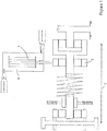
- the SMA engine 1 comprises an SMA actuation core.
- the SMA actuation core is comprised of SMA material clamped or otherwise secured at a first point which is fixed. At the opposing end, the SMA material is clamped or otherwise secured to a drive mechanism 2. Thus whilst the first point is anchored the second point is free to move albeit pulling the drive mechanism 3.
- An immersion chamber 4 adapted for housing the SMA engine and is adapted to be sequentially filled with fluid to allow heating and/or cooling of the SMA engine. Accordingly, as heat is applied to the SMA core it is free to contract.
- the SMA core comprises a plurality of parallel wires, ribbons or sheets of SMA material.
- the term 'wire' is used and should be given a broad interpretation to mean any suitable length of SMA or NTE material that can act as a core.
- NiTi Nickel-Titanium alloy
- This alloy is a well-known Shape-Memory Alloy and has numerous uses across different industries. It will be appreciated that any suitable SMA or NTE material can be used in the context of the present invention.
- the core reacts when exposed to the hot and cold streams of fluid.
- the time of reaction is of most importance when trying to improve the efficiency of power production.
- the present invention proposes a system and method through which the time of reaction for the hot and cold cycles of the system is decreased in duration by providing a pre-heating or cooling step in a chamber.
- a cascade arrangement involves the serial connection of cores such that water flowing from the outlet of one core can be sent to the inlet of another core.
- the purpose of such an arrangement is to increase the efficiency of the system by permitting the maximum recovery of heat from the available source, in this case hot water.
- this enhanced heat recovery can be achieved by using sequential cores comprised of alloys with different activation temperatures.
- cores of the same alloy can be utilised.
- any combination of cores with different alloys can be used (e.g. a plurality of cores with a certain alloy and a separate plurality of cores with a different alloy or alloys). In this way, as the water flows through the core, it activates the sequence of cores at different temperatures, corresponding to the progressively changing temperature of the water.
- the cascading of cores is possible only if the alloy contained in the core is capable to withstand the exposure to a fluid of different temperatures in an efficient way, i.e. to be able to change phase completely, hence obtaining the desired usable deflection. There are two possibilities to enable this:
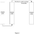
- Figure 2 illustrates a first Shape-Memory Alloy (SMA) or Negative Thermal Expansion (NTE) core 10 and adapted to convert movement of the core into energy in response to a first temperature and a second Shape-Memory Alloy (SMA) or Negative Thermal Expansion (NTE) core 20 in fluid communication with the first core and adapted to convert movement of the second core into energy in response to a second temperature.
- SMA Shape-Memory Alloy
- NTE Negative Thermal Expansion
- transition temperatures are very important after the shape setting of the wires process is finished, since thermal cycling is shifting the transformation temperatures, so the functioning conditions of the non-cycled wire are completely changed.
- a safety measure to ensure that the wire is fit to react while cascading two main power cores with the target to obtain a power output is to anneal the as-received wire. This procedure will shift the activation temperatures of the hysteresis curve, so after the settling process, the risk of having not reacting alloy is not as high.
- the invention reduces to using at maximum the potential contained by the hot/cold fluid in the power cores. If the temperatures of the fluid streams that flow in the installation are outside the hysteresis curve and have high/low enough values to be cycled through two consecutive power cores the efficiency of the installation will increase significantly. The time of the cycle can be reduced as well if the residual fluid/water exciting the two power cores is used to preheat a third power core.
- a cascade arrangement involves the serial connection of cores 10, 20, such that water flowing from the outlet of one core can be sent to the inlet of another core.
- the purpose of such an arrangement is to increase the efficiency of the system, by using better the potential contained by the hot/cold stream.
- the present embodiment makes use of a cascade system of Figure 2 for an SMA/NTE engine, whereby an additional chamber is included in the cascade circuit, between two operating cores.
- Each core contains an alloy which is configured to activate at temperatures different to the preceding core.
- This additional core contains an SMA/NTE working element which can be sized and tasked with, but not limited at, providing power for the operation of various parasitic systems such as valves, pumps etc.
- the power take-off from this core can be mechanical or otherwise.
- This embodiment reduces down to using at maximum the potential contained by the hot/cold fluid in the power core and a core for powering auxiliaries components in the system (i.e. valves, pumps etc.). If the temperatures of the streams that flow in the installation are outside the hysteresis curve and have high/low enough values to be cycled through two consecutive cores the efficiency of the installation will increase significantly. The time of the cycle can be reduced as well if the residual water exiting the two power cores is used to preheat a third power core.
- the transition temperatures are important after the shape setting of the wires process is finished, since thermal cycling is shifting the transformation temperatures, so the functioning conditions of the non-cycled wire are completely changed.
- a safety measure to ensure that the wire is fit to react while cascading two cores (main, auxiliary or a combination), with the target to obtain a power output, is to anneal the as-received wire. This procedure will shift the activation temperatures of the hysteresis curve, so after the settling process, the risk of having not-reacting alloy is not as high.
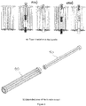
- Figure 3a shows flow circulation in an energy recovery system comprising a number of cores shown in cascade.
- Figure 3b illustrates one of the cores of Figure 3b wherein two bundles are concentrically mounted in the same core to act as two cores.
- the bundles can comprise of alloys with different activation temperatures with one core capable of slotting into another core.
- the activation temperatures of the two types of alloys in the wire bundle cores are as follows:
- An auxiliary core is mounted in the centre of the main power core, as shown in Figure 3b .
- the relation between the activation temperatures for the two alloys that are used in the main and the auxiliary bundles is as follows: (Mf - Ms ⁇ Mfaux - Msaux ⁇ Asaux - Afaux ⁇ As - Af)
- the flow path involves two passings of the same stream of fluid through the same combined core.
- first passing of the hot fluid through the core both bundles would be activated and in this way produce work.
- second passing the temperature of the fluid has to be higher than the Austenite finish (Af) temperature of the auxiliary core and smaller than the Austenite start (As) temperature of the main power producing core, so that the full activation of the auxiliary bundle would take place and a precooling of the main bundle's wires would be achieved.
- Af Austenite finish
- As Austenite start
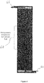
- Figure 4 illustrates a further embodiment showing an inlet 60 and outlet 61 for receiving and discharging fluid from a core.
- the hot/cold fluid delivery system is designed in such a way that, for example, hot fluid is never completely flushed from the core while the cold fluid enters the core (the same is applicable with the cold fluid being flushed from the core while hot fluid enters the core), there will always be a mixing area 62 of the two fluids present, in the form of a wave preceding the fluid that enters last in the heat transfer area.
- the mixing area 62 is of interest since its temperature is important. If the temperature of the mixing area is maintained inside the hysteresis curve (on the hot and on the cold side) it can perform the preheating and the precooling of the wires before the fresh streams of hot/cold fluids at the optimum temperature levels (outside the hysteresis curve) strike the surface of the wires.
- An optimization can be performed to find the optimal temperatures and lengths of the mixing zone to minimize the reaction time of the wires for each core.
- a feature which is desirable in the core is a turbulent flow condition. This helps to increase heat transfer between the fluid and wire.
- Figure 5 shows an embodiment that can be used to act as a regenerator but also to help promote a swirling flow of the fluid.
- Figure 5 shows a piston 70 with a dome 71 attached to its top surface.
- the dome is preferably made of a highly conductive material.
- the dome 71 has paths cut into its surface. These paths provide two purposes. The first is to guide the incoming fluid to create a spiral flow pattern. The second purpose is to increase the area of the dome 71 in contact with the incoming fluid. As a hot fluid enters it will follow the path but also it will transfer heat to the dome material. This causes the hot phase to have a pre-heating phase. When the cool fluid enters the core it will also contact the dome and follow the path. The dome 71 will transfer its heat to the fluid and create a pre-cooling stage.
Landscapes
- Engineering & Computer Science (AREA)
- Chemical & Material Sciences (AREA)
- Combustion & Propulsion (AREA)
- General Engineering & Computer Science (AREA)
- Mechanical Engineering (AREA)
- Physical Or Chemical Processes And Apparatus (AREA)
Applications Claiming Priority (2)
| Application Number | Priority Date | Filing Date | Title |
|---|---|---|---|
| GBGB1511487.9A GB201511487D0 (en) | 2015-06-30 | 2015-06-30 | Method and system for efficiency increase in an energy recovery device |
| PCT/EP2016/065210 WO2017001521A1 (en) | 2015-06-30 | 2016-06-29 | Method and system for efficiency increase in an energy recovery device |
Publications (2)
| Publication Number | Publication Date |
|---|---|
| EP3317535A1 EP3317535A1 (en) | 2018-05-09 |
| EP3317535B1 true EP3317535B1 (en) | 2019-08-07 |
Family
ID=53872465
Family Applications (1)
| Application Number | Title | Priority Date | Filing Date |
|---|---|---|---|
| EP16741542.1A Active EP3317535B1 (en) | 2015-06-30 | 2016-06-29 | Method and system for efficiency increase in an energy recovery device |
Country Status (5)
| Country | Link |
|---|---|
| US (1) | US10288049B2 (enExample) |
| EP (1) | EP3317535B1 (enExample) |
| JP (1) | JP2018519469A (enExample) |
| GB (1) | GB201511487D0 (enExample) |
| WO (1) | WO2017001521A1 (enExample) |
Cited By (5)
| Publication number | Priority date | Publication date | Assignee | Title |
|---|---|---|---|---|
| US12072125B2 (en) | 2019-08-02 | 2024-08-27 | Exergyn Ltd. | System and method for maximising heat output and temperature delta in a SMA heat pump/refrigeration system |
| US12085315B2 (en) | 2019-08-02 | 2024-09-10 | Exergyn Ltd. | Elastocaloric heat recovery in a heat pump / refrigeration system using a pump mechanism |
| US12111084B2 (en) | 2019-08-02 | 2024-10-08 | Exergyn Ltd. | System and method for supporting SMA material and optimising heat transfer in a SMA heat pump |
| US12140346B2 (en) | 2019-08-02 | 2024-11-12 | Exergyn Ltd. | System and method for work recovery in a heat pump |
| US12467678B2 (en) | 2019-08-02 | 2025-11-11 | Exergyn Ltd. | Heat pump and housing for a heat pump |
Families Citing this family (2)
| Publication number | Priority date | Publication date | Assignee | Title |
|---|---|---|---|---|
| GB201709605D0 (en) * | 2017-06-16 | 2017-08-02 | Exergyn Ltd | Energy device core for use in an energy recovery device |
| DE102023208685B3 (de) | 2023-09-08 | 2024-11-28 | Helmholtz-Zentrum Dresden - Rossendorf E. V. | Vorrichtung zur Wandlung thermischer Fluidströmung und mechanischer Arbeit |
Family Cites Families (19)
| Publication number | Priority date | Publication date | Assignee | Title |
|---|---|---|---|---|
| US1536951A (en) * | 1924-07-30 | 1925-05-05 | Buckeye Iron & Brass Works | Cake-forming machine |
| US4027479A (en) * | 1976-05-06 | 1977-06-07 | Cory John S | Variable density heat engine |
| JPS557972A (en) * | 1978-07-03 | 1980-01-21 | Matsushita Electric Ind Co Ltd | Internal combustor |
| DE3014560A1 (de) * | 1980-04-16 | 1981-10-22 | Dieter 7317 Wendlingen Knauer | Waermekratmaschine |
| JPH0354373A (ja) * | 1989-06-08 | 1991-03-08 | Hirotsune Momose | 形状記憶合金の複合体 |
| US5279123A (en) * | 1992-06-04 | 1994-01-18 | Iowa State University Research Foundation, Inc. | Apparatus for recovery and use of waste thermal energy |
| US6543224B1 (en) * | 2002-01-29 | 2003-04-08 | United Technologies Corporation | System and method for controlling shape memory alloy actuators |
| US7980074B2 (en) * | 2006-08-09 | 2011-07-19 | GM Global Technology Operations LLC | Active material actuator assembly |
| US7823382B2 (en) * | 2006-08-09 | 2010-11-02 | Gm Global Technology Operations, Inc. | Active material actuator with modulated movement |
| WO2010023876A1 (ja) * | 2008-08-26 | 2010-03-04 | パナソニック株式会社 | 導電性高分子を用いた流体搬送装置 |
| US7926565B2 (en) * | 2008-10-13 | 2011-04-19 | Baker Hughes Incorporated | Shape memory polyurethane foam for downhole sand control filtration devices |
| JP3147811U (ja) * | 2008-10-13 | 2009-01-22 | 学 林田 | 内燃機関用ピストン。 |
| US8678299B2 (en) * | 2008-10-29 | 2014-03-25 | Korea Institute Of Machinery & Materials | Hollow actuator-driven droplet dispensing apparatus |
| US9727062B2 (en) * | 2011-07-14 | 2017-08-08 | Onesubsea Ip Uk Limited | Shape memory alloy thermostat for subsea equipment |
| GB2497542A (en) * | 2011-12-13 | 2013-06-19 | Dublin Inst Of Technology | Shape memory alloy motor with spring energy accumulator |
| GB201310512D0 (en) | 2013-06-13 | 2013-07-24 | Exergyn Ltd | Pressure Relief System and Method in an Energy Recovery Device |
| GB201310531D0 (en) | 2013-06-13 | 2013-07-31 | Exergyn Ltd | Rotary Pressure Relief System and Method |
| US9581146B2 (en) * | 2013-10-03 | 2017-02-28 | The Boeing Company | Smart susceptor for a shape memory alloy (SMA) actuator inductive heating system |
| GB2533159A (en) * | 2014-12-12 | 2016-06-15 | Exergyn Ltd | Wire element arrangement in an energy recovery device |
-
2015
- 2015-06-30 GB GBGB1511487.9A patent/GB201511487D0/en not_active Ceased
-
2016
- 2016-06-29 US US15/741,021 patent/US10288049B2/en active Active
- 2016-06-29 JP JP2017568055A patent/JP2018519469A/ja active Pending
- 2016-06-29 WO PCT/EP2016/065210 patent/WO2017001521A1/en not_active Ceased
- 2016-06-29 EP EP16741542.1A patent/EP3317535B1/en active Active
Non-Patent Citations (1)
| Title |
|---|
| None * |
Cited By (5)
| Publication number | Priority date | Publication date | Assignee | Title |
|---|---|---|---|---|
| US12072125B2 (en) | 2019-08-02 | 2024-08-27 | Exergyn Ltd. | System and method for maximising heat output and temperature delta in a SMA heat pump/refrigeration system |
| US12085315B2 (en) | 2019-08-02 | 2024-09-10 | Exergyn Ltd. | Elastocaloric heat recovery in a heat pump / refrigeration system using a pump mechanism |
| US12111084B2 (en) | 2019-08-02 | 2024-10-08 | Exergyn Ltd. | System and method for supporting SMA material and optimising heat transfer in a SMA heat pump |
| US12140346B2 (en) | 2019-08-02 | 2024-11-12 | Exergyn Ltd. | System and method for work recovery in a heat pump |
| US12467678B2 (en) | 2019-08-02 | 2025-11-11 | Exergyn Ltd. | Heat pump and housing for a heat pump |
Also Published As
| Publication number | Publication date |
|---|---|
| JP2018519469A (ja) | 2018-07-19 |
| US20180347551A1 (en) | 2018-12-06 |
| EP3317535A1 (en) | 2018-05-09 |
| GB201511487D0 (en) | 2015-08-12 |
| US10288049B2 (en) | 2019-05-14 |
| WO2017001521A1 (en) | 2017-01-05 |
Similar Documents
| Publication | Publication Date | Title |
|---|---|---|
| EP3317535B1 (en) | Method and system for efficiency increase in an energy recovery device | |
| WO2016097214A1 (en) | Heat transfer in an energy recovery device | |
| JP7702144B2 (ja) | ヒートポンプシステム、及び加熱方法 | |
| US12378951B2 (en) | Gas separated cycling of SMA/NTE bundles in a fluid environment for power production cycle or heat pump cycles | |
| WO2018229231A1 (en) | Energy device core for use in an energy recovery device | |
| EP3149327B1 (en) | Bundle holder for use in an energy recovery device | |
| US20190154012A1 (en) | Method and system for dynamic balancing of a core in an energy recovery device | |
| WO2016097070A2 (en) | Heat transfer in an energy recovery device | |
| US11162478B2 (en) | Hydraulic transmission for a SMA engine used in an energy recovery device | |
| EP3317536B1 (en) | Sma bundle wire optimisation in an energy recovery device | |
| EP4291779B1 (en) | Engine operating using a compression sma material | |
| US20190316571A1 (en) | Sma bundle piston cushioning system for use in an energy recovery device |
Legal Events
| Date | Code | Title | Description |
|---|---|---|---|
| STAA | Information on the status of an ep patent application or granted ep patent |
Free format text: STATUS: THE INTERNATIONAL PUBLICATION HAS BEEN MADE |
|
| PUAI | Public reference made under article 153(3) epc to a published international application that has entered the european phase |
Free format text: ORIGINAL CODE: 0009012 |
|
| STAA | Information on the status of an ep patent application or granted ep patent |
Free format text: STATUS: REQUEST FOR EXAMINATION WAS MADE |
|
| STAA | Information on the status of an ep patent application or granted ep patent |
Free format text: STATUS: EXAMINATION IS IN PROGRESS |
|
| 17P | Request for examination filed |
Effective date: 20180129 |
|
| AK | Designated contracting states |
Kind code of ref document: A1 Designated state(s): AL AT BE BG CH CY CZ DE DK EE ES FI FR GB GR HR HU IE IS IT LI LT LU LV MC MK MT NL NO PL PT RO RS SE SI SK SM TR |
|
| AX | Request for extension of the european patent |
Extension state: BA ME |
|
| 17Q | First examination report despatched |
Effective date: 20180502 |
|
| DAV | Request for validation of the european patent (deleted) | ||
| DAX | Request for extension of the european patent (deleted) | ||
| GRAP | Despatch of communication of intention to grant a patent |
Free format text: ORIGINAL CODE: EPIDOSNIGR1 |
|
| STAA | Information on the status of an ep patent application or granted ep patent |
Free format text: STATUS: GRANT OF PATENT IS INTENDED |
|
| INTG | Intention to grant announced |
Effective date: 20190129 |
|
| RIN1 | Information on inventor provided before grant (corrected) |
Inventor name: WARREN, KEITH Inventor name: TIRCA-DRAGOMIRESCU, GEORGIANA |
|
| GRAS | Grant fee paid |
Free format text: ORIGINAL CODE: EPIDOSNIGR3 |
|
| GRAA | (expected) grant |
Free format text: ORIGINAL CODE: 0009210 |
|
| STAA | Information on the status of an ep patent application or granted ep patent |
Free format text: STATUS: THE PATENT HAS BEEN GRANTED |
|
| AK | Designated contracting states |
Kind code of ref document: B1 Designated state(s): AL AT BE BG CH CY CZ DE DK EE ES FI FR GB GR HR HU IE IS IT LI LT LU LV MC MK MT NL NO PL PT RO RS SE SI SK SM TR |
|
| REG | Reference to a national code |
Ref country code: GB Ref legal event code: FG4D |
|
| REG | Reference to a national code |
Ref country code: CH Ref legal event code: EP Ref country code: AT Ref legal event code: REF Ref document number: 1164292 Country of ref document: AT Kind code of ref document: T Effective date: 20190815 |
|
| REG | Reference to a national code |
Ref country code: DE Ref legal event code: R096 Ref document number: 602016018215 Country of ref document: DE |
|
| REG | Reference to a national code |
Ref country code: IE Ref legal event code: FG4D |
|
| REG | Reference to a national code |
Ref country code: NL Ref legal event code: MP Effective date: 20190807 |
|
| REG | Reference to a national code |
Ref country code: LT Ref legal event code: MG4D |
|
| PG25 | Lapsed in a contracting state [announced via postgrant information from national office to epo] |
Ref country code: PT Free format text: LAPSE BECAUSE OF FAILURE TO SUBMIT A TRANSLATION OF THE DESCRIPTION OR TO PAY THE FEE WITHIN THE PRESCRIBED TIME-LIMIT Effective date: 20191209 Ref country code: LT Free format text: LAPSE BECAUSE OF FAILURE TO SUBMIT A TRANSLATION OF THE DESCRIPTION OR TO PAY THE FEE WITHIN THE PRESCRIBED TIME-LIMIT Effective date: 20190807 Ref country code: SE Free format text: LAPSE BECAUSE OF FAILURE TO SUBMIT A TRANSLATION OF THE DESCRIPTION OR TO PAY THE FEE WITHIN THE PRESCRIBED TIME-LIMIT Effective date: 20190807 Ref country code: NO Free format text: LAPSE BECAUSE OF FAILURE TO SUBMIT A TRANSLATION OF THE DESCRIPTION OR TO PAY THE FEE WITHIN THE PRESCRIBED TIME-LIMIT Effective date: 20191107 Ref country code: NL Free format text: LAPSE BECAUSE OF FAILURE TO SUBMIT A TRANSLATION OF THE DESCRIPTION OR TO PAY THE FEE WITHIN THE PRESCRIBED TIME-LIMIT Effective date: 20190807 Ref country code: BG Free format text: LAPSE BECAUSE OF FAILURE TO SUBMIT A TRANSLATION OF THE DESCRIPTION OR TO PAY THE FEE WITHIN THE PRESCRIBED TIME-LIMIT Effective date: 20191107 Ref country code: HR Free format text: LAPSE BECAUSE OF FAILURE TO SUBMIT A TRANSLATION OF THE DESCRIPTION OR TO PAY THE FEE WITHIN THE PRESCRIBED TIME-LIMIT Effective date: 20190807 Ref country code: FI Free format text: LAPSE BECAUSE OF FAILURE TO SUBMIT A TRANSLATION OF THE DESCRIPTION OR TO PAY THE FEE WITHIN THE PRESCRIBED TIME-LIMIT Effective date: 20190807 |
|
| REG | Reference to a national code |
Ref country code: AT Ref legal event code: MK05 Ref document number: 1164292 Country of ref document: AT Kind code of ref document: T Effective date: 20190807 |
|
| PG25 | Lapsed in a contracting state [announced via postgrant information from national office to epo] |
Ref country code: IS Free format text: LAPSE BECAUSE OF FAILURE TO SUBMIT A TRANSLATION OF THE DESCRIPTION OR TO PAY THE FEE WITHIN THE PRESCRIBED TIME-LIMIT Effective date: 20191207 Ref country code: RS Free format text: LAPSE BECAUSE OF FAILURE TO SUBMIT A TRANSLATION OF THE DESCRIPTION OR TO PAY THE FEE WITHIN THE PRESCRIBED TIME-LIMIT Effective date: 20190807 Ref country code: ES Free format text: LAPSE BECAUSE OF FAILURE TO SUBMIT A TRANSLATION OF THE DESCRIPTION OR TO PAY THE FEE WITHIN THE PRESCRIBED TIME-LIMIT Effective date: 20190807 Ref country code: GR Free format text: LAPSE BECAUSE OF FAILURE TO SUBMIT A TRANSLATION OF THE DESCRIPTION OR TO PAY THE FEE WITHIN THE PRESCRIBED TIME-LIMIT Effective date: 20191108 Ref country code: AL Free format text: LAPSE BECAUSE OF FAILURE TO SUBMIT A TRANSLATION OF THE DESCRIPTION OR TO PAY THE FEE WITHIN THE PRESCRIBED TIME-LIMIT Effective date: 20190807 Ref country code: LV Free format text: LAPSE BECAUSE OF FAILURE TO SUBMIT A TRANSLATION OF THE DESCRIPTION OR TO PAY THE FEE WITHIN THE PRESCRIBED TIME-LIMIT Effective date: 20190807 |
|
| PG25 | Lapsed in a contracting state [announced via postgrant information from national office to epo] |
Ref country code: TR Free format text: LAPSE BECAUSE OF FAILURE TO SUBMIT A TRANSLATION OF THE DESCRIPTION OR TO PAY THE FEE WITHIN THE PRESCRIBED TIME-LIMIT Effective date: 20190807 |
|
| PG25 | Lapsed in a contracting state [announced via postgrant information from national office to epo] |
Ref country code: RO Free format text: LAPSE BECAUSE OF FAILURE TO SUBMIT A TRANSLATION OF THE DESCRIPTION OR TO PAY THE FEE WITHIN THE PRESCRIBED TIME-LIMIT Effective date: 20190807 Ref country code: DK Free format text: LAPSE BECAUSE OF FAILURE TO SUBMIT A TRANSLATION OF THE DESCRIPTION OR TO PAY THE FEE WITHIN THE PRESCRIBED TIME-LIMIT Effective date: 20190807 Ref country code: IT Free format text: LAPSE BECAUSE OF FAILURE TO SUBMIT A TRANSLATION OF THE DESCRIPTION OR TO PAY THE FEE WITHIN THE PRESCRIBED TIME-LIMIT Effective date: 20190807 Ref country code: EE Free format text: LAPSE BECAUSE OF FAILURE TO SUBMIT A TRANSLATION OF THE DESCRIPTION OR TO PAY THE FEE WITHIN THE PRESCRIBED TIME-LIMIT Effective date: 20190807 Ref country code: AT Free format text: LAPSE BECAUSE OF FAILURE TO SUBMIT A TRANSLATION OF THE DESCRIPTION OR TO PAY THE FEE WITHIN THE PRESCRIBED TIME-LIMIT Effective date: 20190807 Ref country code: PL Free format text: LAPSE BECAUSE OF FAILURE TO SUBMIT A TRANSLATION OF THE DESCRIPTION OR TO PAY THE FEE WITHIN THE PRESCRIBED TIME-LIMIT Effective date: 20190807 |
|
| PG25 | Lapsed in a contracting state [announced via postgrant information from national office to epo] |
Ref country code: CZ Free format text: LAPSE BECAUSE OF FAILURE TO SUBMIT A TRANSLATION OF THE DESCRIPTION OR TO PAY THE FEE WITHIN THE PRESCRIBED TIME-LIMIT Effective date: 20190807 Ref country code: SK Free format text: LAPSE BECAUSE OF FAILURE TO SUBMIT A TRANSLATION OF THE DESCRIPTION OR TO PAY THE FEE WITHIN THE PRESCRIBED TIME-LIMIT Effective date: 20190807 Ref country code: SM Free format text: LAPSE BECAUSE OF FAILURE TO SUBMIT A TRANSLATION OF THE DESCRIPTION OR TO PAY THE FEE WITHIN THE PRESCRIBED TIME-LIMIT Effective date: 20190807 Ref country code: IS Free format text: LAPSE BECAUSE OF FAILURE TO SUBMIT A TRANSLATION OF THE DESCRIPTION OR TO PAY THE FEE WITHIN THE PRESCRIBED TIME-LIMIT Effective date: 20200224 |
|
| REG | Reference to a national code |
Ref country code: DE Ref legal event code: R097 Ref document number: 602016018215 Country of ref document: DE |
|
| PLBE | No opposition filed within time limit |
Free format text: ORIGINAL CODE: 0009261 |
|
| STAA | Information on the status of an ep patent application or granted ep patent |
Free format text: STATUS: NO OPPOSITION FILED WITHIN TIME LIMIT |
|
| PG2D | Information on lapse in contracting state deleted |
Ref country code: IS |
|
| 26N | No opposition filed |
Effective date: 20200603 |
|
| PG25 | Lapsed in a contracting state [announced via postgrant information from national office to epo] |
Ref country code: SI Free format text: LAPSE BECAUSE OF FAILURE TO SUBMIT A TRANSLATION OF THE DESCRIPTION OR TO PAY THE FEE WITHIN THE PRESCRIBED TIME-LIMIT Effective date: 20190807 |
|
| PG25 | Lapsed in a contracting state [announced via postgrant information from national office to epo] |
Ref country code: MC Free format text: LAPSE BECAUSE OF FAILURE TO SUBMIT A TRANSLATION OF THE DESCRIPTION OR TO PAY THE FEE WITHIN THE PRESCRIBED TIME-LIMIT Effective date: 20190807 |
|
| REG | Reference to a national code |
Ref country code: CH Ref legal event code: PL |
|
| PG25 | Lapsed in a contracting state [announced via postgrant information from national office to epo] |
Ref country code: LU Free format text: LAPSE BECAUSE OF NON-PAYMENT OF DUE FEES Effective date: 20200629 |
|
| REG | Reference to a national code |
Ref country code: BE Ref legal event code: MM Effective date: 20200630 |
|
| PG25 | Lapsed in a contracting state [announced via postgrant information from national office to epo] |
Ref country code: CH Free format text: LAPSE BECAUSE OF NON-PAYMENT OF DUE FEES Effective date: 20200630 Ref country code: LI Free format text: LAPSE BECAUSE OF NON-PAYMENT OF DUE FEES Effective date: 20200630 |
|
| PG25 | Lapsed in a contracting state [announced via postgrant information from national office to epo] |
Ref country code: BE Free format text: LAPSE BECAUSE OF NON-PAYMENT OF DUE FEES Effective date: 20200630 |
|
| PG25 | Lapsed in a contracting state [announced via postgrant information from national office to epo] |
Ref country code: MT Free format text: LAPSE BECAUSE OF FAILURE TO SUBMIT A TRANSLATION OF THE DESCRIPTION OR TO PAY THE FEE WITHIN THE PRESCRIBED TIME-LIMIT Effective date: 20190807 Ref country code: CY Free format text: LAPSE BECAUSE OF FAILURE TO SUBMIT A TRANSLATION OF THE DESCRIPTION OR TO PAY THE FEE WITHIN THE PRESCRIBED TIME-LIMIT Effective date: 20190807 |
|
| PG25 | Lapsed in a contracting state [announced via postgrant information from national office to epo] |
Ref country code: MK Free format text: LAPSE BECAUSE OF FAILURE TO SUBMIT A TRANSLATION OF THE DESCRIPTION OR TO PAY THE FEE WITHIN THE PRESCRIBED TIME-LIMIT Effective date: 20190807 |
|
| P01 | Opt-out of the competence of the unified patent court (upc) registered |
Effective date: 20230602 |
|
| PGFP | Annual fee paid to national office [announced via postgrant information from national office to epo] |
Ref country code: DE Payment date: 20250626 Year of fee payment: 10 |
|
| PGFP | Annual fee paid to national office [announced via postgrant information from national office to epo] |
Ref country code: GB Payment date: 20250611 Year of fee payment: 10 |
|
| PGFP | Annual fee paid to national office [announced via postgrant information from national office to epo] |
Ref country code: FR Payment date: 20250623 Year of fee payment: 10 |
|
| PGFP | Annual fee paid to national office [announced via postgrant information from national office to epo] |
Ref country code: IE Payment date: 20250611 Year of fee payment: 10 |