EP3317461B1 - Protector - Google Patents
Protector Download PDFInfo
- Publication number
- EP3317461B1 EP3317461B1 EP16738873.5A EP16738873A EP3317461B1 EP 3317461 B1 EP3317461 B1 EP 3317461B1 EP 16738873 A EP16738873 A EP 16738873A EP 3317461 B1 EP3317461 B1 EP 3317461B1
- Authority
- EP
- European Patent Office
- Prior art keywords
- layer
- thermal protection
- sheath
- cable
- thermal
- Prior art date
- Legal status (The legal status is an assumption and is not a legal conclusion. Google has not performed a legal analysis and makes no representation as to the accuracy of the status listed.)
- Active
Links
- 230000001012 protector Effects 0.000 title 1
- 238000009413 insulation Methods 0.000 claims description 84
- 239000002131 composite material Substances 0.000 claims description 67
- 239000004744 fabric Substances 0.000 claims description 26
- 239000000463 material Substances 0.000 claims description 25
- 239000012774 insulation material Substances 0.000 claims description 15
- 239000000835 fiber Substances 0.000 claims description 11
- VYPSYNLAJGMNEJ-UHFFFAOYSA-N Silicium dioxide Chemical compound O=[Si]=O VYPSYNLAJGMNEJ-UHFFFAOYSA-N 0.000 claims description 8
- 239000000378 calcium silicate Substances 0.000 claims description 6
- 229910052918 calcium silicate Inorganic materials 0.000 claims description 6
- OYACROKNLOSFPA-UHFFFAOYSA-N calcium;dioxido(oxo)silane Chemical compound [Ca+2].[O-][Si]([O-])=O OYACROKNLOSFPA-UHFFFAOYSA-N 0.000 claims description 6
- 239000000203 mixture Substances 0.000 claims description 6
- 239000002245 particle Substances 0.000 claims description 6
- 239000000919 ceramic Substances 0.000 claims description 5
- 239000011521 glass Substances 0.000 claims description 5
- 229910052500 inorganic mineral Inorganic materials 0.000 claims description 5
- 239000011707 mineral Substances 0.000 claims description 5
- 230000001681 protective effect Effects 0.000 claims description 5
- PNEYBMLMFCGWSK-UHFFFAOYSA-N aluminium oxide Inorganic materials [O-2].[O-2].[O-2].[Al+3].[Al+3] PNEYBMLMFCGWSK-UHFFFAOYSA-N 0.000 claims description 4
- 239000000377 silicon dioxide Substances 0.000 claims description 4
- 230000002209 hydrophobic effect Effects 0.000 claims description 3
- 230000002787 reinforcement Effects 0.000 claims description 2
- 239000010410 layer Substances 0.000 description 242
- 229910000831 Steel Inorganic materials 0.000 description 20
- 239000004567 concrete Substances 0.000 description 20
- 239000010959 steel Substances 0.000 description 20
- 238000009434 installation Methods 0.000 description 18
- 210000002435 tendon Anatomy 0.000 description 17
- 230000000694 effects Effects 0.000 description 8
- 238000012423 maintenance Methods 0.000 description 7
- 238000010276 construction Methods 0.000 description 6
- 229930195733 hydrocarbon Natural products 0.000 description 6
- 150000002430 hydrocarbons Chemical class 0.000 description 6
- 238000012546 transfer Methods 0.000 description 6
- 239000004215 Carbon black (E152) Substances 0.000 description 5
- 239000011810 insulating material Substances 0.000 description 5
- 210000002268 wool Anatomy 0.000 description 5
- 229960003340 calcium silicate Drugs 0.000 description 4
- 235000012241 calcium silicate Nutrition 0.000 description 4
- 230000006378 damage Effects 0.000 description 4
- 238000006073 displacement reaction Methods 0.000 description 4
- 230000005284 excitation Effects 0.000 description 4
- 229920001903 high density polyethylene Polymers 0.000 description 4
- 239000004700 high-density polyethylene Substances 0.000 description 4
- 238000004519 manufacturing process Methods 0.000 description 4
- 238000000034 method Methods 0.000 description 4
- 230000002829 reductive effect Effects 0.000 description 4
- 239000002689 soil Substances 0.000 description 4
- 238000005452 bending Methods 0.000 description 3
- 238000013016 damping Methods 0.000 description 3
- 239000000446 fuel Substances 0.000 description 3
- 239000011440 grout Substances 0.000 description 3
- 238000010438 heat treatment Methods 0.000 description 3
- 238000007689 inspection Methods 0.000 description 3
- 239000011241 protective layer Substances 0.000 description 3
- 238000009420 retrofitting Methods 0.000 description 3
- 239000000243 solution Substances 0.000 description 3
- 238000012360 testing method Methods 0.000 description 3
- 230000004888 barrier function Effects 0.000 description 2
- 230000015572 biosynthetic process Effects 0.000 description 2
- 230000008859 change Effects 0.000 description 2
- 230000000295 complement effect Effects 0.000 description 2
- 230000006835 compression Effects 0.000 description 2
- 238000007906 compression Methods 0.000 description 2
- 239000000109 continuous material Substances 0.000 description 2
- 230000008878 coupling Effects 0.000 description 2
- 238000010168 coupling process Methods 0.000 description 2
- 238000005859 coupling reaction Methods 0.000 description 2
- 230000007613 environmental effect Effects 0.000 description 2
- 238000002347 injection Methods 0.000 description 2
- 239000007924 injection Substances 0.000 description 2
- 239000011229 interlayer Substances 0.000 description 2
- 238000005259 measurement Methods 0.000 description 2
- 239000000843 powder Substances 0.000 description 2
- 230000005855 radiation Effects 0.000 description 2
- 230000009467 reduction Effects 0.000 description 2
- 230000000284 resting effect Effects 0.000 description 2
- 239000007787 solid Substances 0.000 description 2
- 239000000758 substrate Substances 0.000 description 2
- 239000011800 void material Substances 0.000 description 2
- 229920000271 Kevlar® Polymers 0.000 description 1
- BPQQTUXANYXVAA-UHFFFAOYSA-N Orthosilicate Chemical compound [O-][Si]([O-])([O-])[O-] BPQQTUXANYXVAA-UHFFFAOYSA-N 0.000 description 1
- 239000004698 Polyethylene Substances 0.000 description 1
- 238000004873 anchoring Methods 0.000 description 1
- 238000009435 building construction Methods 0.000 description 1
- 239000004568 cement Substances 0.000 description 1
- 229910010293 ceramic material Inorganic materials 0.000 description 1
- 239000004020 conductor Substances 0.000 description 1
- 238000007596 consolidation process Methods 0.000 description 1
- 230000007423 decrease Effects 0.000 description 1
- 230000001934 delay Effects 0.000 description 1
- 230000001627 detrimental effect Effects 0.000 description 1
- 238000005538 encapsulation Methods 0.000 description 1
- 238000005530 etching Methods 0.000 description 1
- 229910021485 fumed silica Inorganic materials 0.000 description 1
- 230000006870 function Effects 0.000 description 1
- 239000007789 gas Substances 0.000 description 1
- 239000003365 glass fiber Substances 0.000 description 1
- 239000011491 glass wool Substances 0.000 description 1
- 239000004519 grease Substances 0.000 description 1
- 239000004761 kevlar Substances 0.000 description 1
- 230000002045 lasting effect Effects 0.000 description 1
- 230000000670 limiting effect Effects 0.000 description 1
- 239000003949 liquefied natural gas Substances 0.000 description 1
- 239000007788 liquid Substances 0.000 description 1
- 230000007246 mechanism Effects 0.000 description 1
- 239000007769 metal material Substances 0.000 description 1
- 230000036961 partial effect Effects 0.000 description 1
- -1 polyethylene Polymers 0.000 description 1
- 229920000573 polyethylene Polymers 0.000 description 1
- 230000036316 preload Effects 0.000 description 1
- 239000011253 protective coating Substances 0.000 description 1
- 230000009993 protective function Effects 0.000 description 1
- 230000004044 response Effects 0.000 description 1
- 230000002441 reversible effect Effects 0.000 description 1
- 239000011435 rock Substances 0.000 description 1
- 238000007789 sealing Methods 0.000 description 1
- 125000006850 spacer group Chemical group 0.000 description 1
- 229910001220 stainless steel Inorganic materials 0.000 description 1
- 239000010935 stainless steel Substances 0.000 description 1
- 238000003860 storage Methods 0.000 description 1
- 239000000725 suspension Substances 0.000 description 1
- 230000003685 thermal hair damage Effects 0.000 description 1
- 239000012815 thermoplastic material Substances 0.000 description 1
- 230000007704 transition Effects 0.000 description 1
- 229910052902 vermiculite Inorganic materials 0.000 description 1
- 239000010455 vermiculite Substances 0.000 description 1
- 235000019354 vermiculite Nutrition 0.000 description 1
- 230000000007 visual effect Effects 0.000 description 1
- XLYOFNOQVPJJNP-UHFFFAOYSA-N water Substances O XLYOFNOQVPJJNP-UHFFFAOYSA-N 0.000 description 1
- 239000001993 wax Substances 0.000 description 1
- 238000003466 welding Methods 0.000 description 1
Images


Classifications
-
- E—FIXED CONSTRUCTIONS
- E02—HYDRAULIC ENGINEERING; FOUNDATIONS; SOIL SHIFTING
- E02D—FOUNDATIONS; EXCAVATIONS; EMBANKMENTS; UNDERGROUND OR UNDERWATER STRUCTURES
- E02D5/00—Bulkheads, piles, or other structural elements specially adapted to foundation engineering
- E02D5/74—Means for anchoring structural elements or bulkheads
- E02D5/80—Ground anchors
-
- E—FIXED CONSTRUCTIONS
- E21—EARTH DRILLING; MINING
- E21D—SHAFTS; TUNNELS; GALLERIES; LARGE UNDERGROUND CHAMBERS
- E21D21/00—Anchoring-bolts for roof, floor in galleries or longwall working, or shaft-lining protection
Definitions
- the present invention concerns an insulation system arrangement for the thermal protection of elongated structural elements.
- the present invention concerns the thermal protection of cylindrical structures including cylindrical load bearing structures, tensile members and their anchorage components or tensioned cables found in external post-tensioning tendons or stay cables including their end anchorages.
- Such elongated structural elements typically use high strength material, for example high strength cold-drawn steel, to allow for the transfer of concentrated forces through lightweight elements having small cross sections, notably used for the transfer of forces in bridges, buildings, special pressure containment structures, retaining walls and other structures built primarily of concrete or steel.
- these tensile elements are pre-tensioned in order to apply a significant pre-load, also called pre-stress, to the surrounding structure.
- Said invention relates to a cylindrical sheath for the thermal protection of elongated structural elements, and notably for post-tensioning tendons, stay cables and the like.
- a sheath forms a sleeve to be fitted around a running portion of a cable, a tendon or a pipe. More generally, this sheath can serve as thermal protection for a length of any structural elongated element made from high tensile steel or other high tensile strength materials susceptible to thermal damage.
- Said sheath can further be adapted in shape such as to also provide protection for zones where the running portion of a cable penetrates through members of the surrounding or supported structure.
- Said sheath can be combined with a cylindrical cap to protect the end terminations of such cables.
- Said invention also relates to a cylindrical cap for the thermal protection of end terminations of structural elements, and notably for end anchorages of post-tensioning tendons, stay cables or ground anchors and the like.
- a cap forms a cover to be installed over an anchorage/pipe, notably an anchorage end or a pipe end.
- This cap can serve in particular as thermal protection for the end of any structural elongated element made from high tensile strength steel or other high tensile strength material.
- the present invention concerns the protection against extreme thermal loading scenarios that result for example from hydrocarbon fires.
- Elongated structural elements on many different types of structures can be exposed to such fire events as a result of accidents or wilfully caused, for example vehicle or ship impact or spills with the subsequent burning of fuel, burning of hydrocarbon materials used in construction or maintenance operations or other unplanned events during the lifetime of the structure involving hydrocarbon materials in a solid, liquid or gas state.
- Such extreme loading scenarios typically result in temperatures exceeding 600°C, and in some cases exceeding 1000°C in confined or unconfined environments with durations which can well exceed 30 minutes, and sometimes in excess of 60 or even 90 minutes.
- End anchorages of such structural elongated elements conventionally rely on mechanical anchorage by direct bearing or friction or bonding between different materials to secure highly stressed elements at their end to the surrounding structure. These end anchorages can either be directly exposed to a fire event or can experience excessive heating when a fire event occurs close to the running length of the cable and the cable acts subsequently as a heat conductor.
- end anchorages participate on satisfying general loading scenarios of the structural elements.
- the relaxation percentage of high tensile strength materials typically increases and their strength decreases.
- Cold-drawn high tensile strength steel is particularly affected by this phenomenon as the strength gain achieved by cold forming the steel during its manufacturing is largely reversed by heating above a critical temperature, consequently resulting in a loss of pre-stressing forces and a general reduction in structural resistance. Furthermore excessive heating can lead to slippage or failure of the stressed element in the end anchorage.
- Surrounding concrete or other structural or protective layers along a member's span often protect(s) the high strength steel from such an undesirable increase in temperature, reducing the likelihood of extensive thermal relaxation and strength loss.
- End anchorage arrangements, as well as tensile members external to a structure however remain susceptible as the anchorages are typically exposed to the heightened temperatures during an extreme thermal event.
- the running part of elongated structural members such as external post-tensioning cables and in particular stay cables is free to move under various effects such as changes in longitudinal elongation, variation of cable sag due to changes in axial cable force or changes of its deformed alignment due to changing lateral loads, such as wind drag forces, or due to vibrations caused by excitation of the cable due to wind effects or by excitation through coupling with vibrations of the structure caused by fluctuating loads or other external effects.
- the geometrical curve which the running part of the cable adopts can vary and relatively large movements can occur relative to the surrounding or supported structure and the cable's end anchorage.
- any thermal protection sheath provided for the running length of the cable must be able to adopt its shape to the changing sag line of the cable as well as allowing for relatively large local displacements at the interface between the thermal protection elements and the surrounding structure.
- the self weight of the sheath must remain small compared to the self weight of the cable if it is supported by the cable in order not to excessively increase the cable sag.
- any thermal protection sheath needs to be easy to remove for the purpose of inspection, maintenance and possible replacement of such devices during the lifetime of the structure.
- the sheath must therefore be lightweight and modular.
- stay cables typically support bridge decks, suspended roof structures or tall masts and towers which are all exposed to horizontal wind loads.
- the horizontal loads generated by wind drag on the stay cables can be a substantial part of the total horizontal loading on the structure (exceeding in some cases 50% of the total horizontal wind load).
- it is of utmost importance to minimize the wind drag by limiting the outer diameter of the stay cables and fitting them with aerodynamically optimized surfaces. Any thermal protection sheath fitted to the cable must hence remain small in diameter.
- thermal insulating properties of these conventional insulation materials do not suffice in the protection of structural elements during extreme thermal loading scenarios that typically exceed temperatures of 1000°C for exposure durations of 30 minutes or more.
- surface applied intumescent products form a protective coating for structural elements such that when exposed to a fire load for a small exposure interval, satisfactory element protection is provided.
- such methods and materials do not provide extended protection as they typically fail to reduce the conduction of thermal energy into the structural element during extended high temperature exposure intervals.
- they are susceptible to mechanical damage as they cannot be covered by additional protective layers due to the need to allow their free expansion to achieve the protective function.
- WO2007093703 relates to a fire protection device for a stay cable formed by two blankets wrapped around the cable, and overlapping each other. Also, an outer shell is covering the stacked blankets, this outer shell being made of high density polyethylene (HDPE).
- HDPE high density polyethylene
- WO2012052796 provides a thermally insulating rigid tube arranged around a stay cable with a thermally insulating material having a minimum thickness requiring an air channel between the insulating tube and the cable and a significant height difference to achieve heat evacuation by convection.
- Such an arrangement is rigid and cannot therefore accommodate the flexure which occurs along the running length of the cable under varying cable sag or the large relative displacements at the interface where the cable penetrates the supported structure during normal working conditions.
- Such an arrangement can only ensure the required freedom of movement of the cable by providing a very large air gap between the rigid tube and the cable resulting in a significant increase of cable diameter having an undesirable impact on the visual appearance of the cable, increasing the required lateral clearance to adjacent parts of the structure and increasing the wind drag of the cable.
- said sandwich-like composite insulation system has a thermal conductivity at 800°C lower than or equal to 0.10 W/m.°C and preferably lower than or equal to 0.09 W/m.°C.
- a thermal protection sheath forms a thin multi-layered composite construction developed for the extreme extended thermal protection of length of elongated structural elements, such as external post-tensioning cables, cable stays, roof suspension elements, steel profiles and pipe ends, and in particular post-tensioning tendons and cable stay end anchorages.
- the invention also relates to a thermal protection device comprising the cylindrical thermal protection sheath and a cylindrical thermal protection cap which forms an extreme extended thermal protection of end terminations of elongated structural elements.
- the invention also relates to an elongated structural device comprising a tensioned cable (or any other elongated structural element) with a running part and at least one anchorage part at the end of the cable, and at least one thermal protection sheath as previously described, wherein said cylindrical thermal protection sheath covers a length of the running cable extending from the anchorage part.
- this elongated structural device further comprises an outer cover enclosing the thermal protection sheath.
- Such a cylindrical cap forms a thermal insulating protection cap comprising of a multi-layered composite construction developed for the extreme extended thermal protection of end terminations of elongated structural elements, such as post-tensioning cables, cable stays, ground anchors, steel profiles and pipe ends, and in particular post-tensioning tendons and cable stay end anchorages.
- the present invention comprises a durable outer first layer having a protective outer side, which is a metallic, metallic-like or non-metallic outer side, such as an aluminized fabric or any other reflective layer, for mechanical protection of the composite construction and increased heat reflection of thermal radiation.
- This outer first layer is preferably fixed with inter-layered stitching to a series of specifically arranged thermal insulating materials.
- the thermal insulation materials preferably consist of both semi-rigid and formable materials which enable the composite cap to form a general cylindrical shape for generic size fabrication.
- the second layer and third layer each form a composite insulating layer, are preferably inter-stitched, and are overlapped with respect to each other in order to provide extensive coverage of the protected system (elongated element such as a tensioned cable end anchorage) and increase overall system efficacy.
- Each composite layer spans the circumference of the cylindrical protection cap and consists of various potential insulating materials, of low thermal conductivity, in order to provide both added strength and reduced thermal conduction.
- the third layer comprises numerous thermal insulating materials of both the fibrous and porous types.
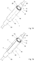
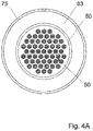
- the thermal protection sheath 1 forms a sleeve of tubular shape, open at both ends. Therefore, the tubular thermal protection sheath 1 is formed by a wall 2 consisting of layers forming a sandwich. These layers form a composite insulation system. Preferably, the thickness and the dimensions (including the diameters when the sheath is formed) of the individual layers of thermal insulation materials are such that there is contact between the adjacent layers. In such a configuration, the layers are stacked in the sandwich like structure of the composite insulation system. A large circular opening 3 is therefore formed at both ends of the tubular thermal protection sheath 1, to allow for the introduction over the element 80 to be protected.
- the sheath 1 has a tubular shape with a section which can be circular or non-circular (for instance a shape such as oval, elliptic, rectangular, square, other quadrilateral or more generally other polygonal shapes).
- tubular thermal protection sheath 1 is further fitted with one or several longitudinal joints 4 allowing opening of the tubular section and hence retrofitting over an already installed element to be protected.
- the materials forming the overlap are preferably staggered, thus resulting in a continuous material thickness around the circumference of the system.
- outer layers 10, 12 and 16 form together a first step 4 1 and inner layers 18 and 20 form together a second step 4 2 , offset with respect to the first step 4 1 .
- the direction of the offset between the first step 4 1 and the second step 4 2 is inversed for the longitudinal edges of the sheath 1, so that formation of the longitudinal joint 4 is obtained through abutting these two longitudinal edges of the sheath 1 which shape are therefore complementary and can fit together with contact.
- the composite insulation system is composed of five layers, hereinafter mentioned as first layer 10, second layer 12, third layer 16, fourth layer 18 and fifth layer 20, from the outermost layer to the innermost layer of the composite insulation system.
- the first layer 10 is a protective layer formed of metallic, metallic-like or non-metallic material being made preferably of a reflecting material such as aluminized reflective fabric. More generally, this first layer 10 has preferably a metallic-like outer face reflecting thermal energy.
- This first outer layer 10 provides the external layering of said composite insulation system and of said cylindrical thermal protection sheath 1: it forms an outer cover.
- this is a protective outer cover providing protection to the rest of the sheath 1, notably against mechanical damages (such as etching or wear) and/or atmospheric exposure (such as ultraviolet rays protection).
- the first (outer) layer 10 is for instance formed by a rectangular piece attached together by stitching 14 to form a cover that encompasses the entirety of said sheath external area.
- This first layer 10 such as an aluminized reflective fabric, serves in an embodiment to reflect thermal radiation, thus reducing thermal energy input into subsequent internal layers of the composite insulation system.
- This first layer 10 also serves as thermal insulation.
- the first layer 10 is preferably durable, water resistant and has a high tear resistance.
- the yarn stitching 14 is of a double stitched weave to provide system robustness. Also as a preferred composition of the yarn material of the stitching 14, one can choose stainless steel or other high temperature material such as glass fibre or Kevlar based fibre, or similar high-strength, high temperature materials, or any mixture thereof.
- the first layer 10 can be omitted: this can particularly occur when another outer element covers, and therefore protects, the composite insulation system.
- an external protection can be provided by other means, i.e. for instance an outer pipe (not illustrated in Figs.1A and 1B ) wrapping the thermal protection sheath 1, which outer pipe can be a HDPE pipe or a steel pipe.
- the second layer 12 forms the layer below the first layer 10 (or this second layer 12 constitutes a first outer layer when there is no layer 10).
- the second layer 12 is covering the inner side surface of the first layer 10.
- This second layer 12 is placed directly against the inner side of the first layer 10.
- the second layer 12 is bi-axially inter-stitched to the first layer 10 with stitching 14.
- the first and second layers 10 and 12 form together an outer assembly of the composite insulation system and of the tubular protection sheath 1.
- the first layer 10 is formed by the above-mentioned rectangular piece with two ends which overlap at the circumference interface and are stitched. Therefore the first layer 10 is individually stitched with stitching 14.
- the second layer 12 has a layout analogous to that of the first layer 10, the circumferential position of the overlapping ends of the rectangular piece for the second layer 12 being staggered with respect to the circumferential position of the overlapping ends of the rectangular piece of the first layer 10.
- the first layer 10 and the second layer 12 are set such that the stitched connections are staggered providing continuous cover outside or inside the respective stitching.
- the stitching 14 previously mentioned is made with a thermal resistant thread 15.
- the second layer 12 is a fabric consisting of filaments and yarns. These yarns can be reinforced yarns: they serve to reinforce the filaments of the fabric. Therefore, the second layer 12 is essentially a primary continuous filament fabric.
- the fabric is a high strength insulation fabric.
- the fabric is a high temperature resistant fabric. Consequently, the second layer 12 brings cohesion within the composite insulation system.
- said filaments primarily consist of fabric, preferably mineral fabric, for instance a vermiculite fabric.
- This second layer 12 serves as a high temperature reinforced fabric for added thermal protection and added overall strength to the thermal protection sheath 1.
- the second layer 12 contributes to the structural integrity of the composite insulation system.
- the third layer 16 Facing the inner side of said second layer 12 is placed the third layer 16 made of or mainly formed by a thermal insulation layer which is essentially made from fibers. These fibers are preferably formed by mineral materials. Preferably, said fibers of said third layer 16 are made from any of the following materials: ceramic, glass or other mineral material. Said thermal insulation layer is therefore preferably ceramic wool, a glass wool or any similar material. This third layer 16 preferably forms a thermal wool insulation layer, with fibers which may be of a mineral or glass composition with a total bulk density relative to the level of thermal protection required. The third layer 16 is covering all the inner side surface of the second layer 12. This third layer 16 is placed directly against the inner side of the second layer 12.
- the third layer is formed by a fibrous ceramic wool that enhances thermal insulation properties with a low thermal conductivity.
- said third layer 16 has a thermal conductivity at 200°C equal to or lower than 0.08 W/m.°C , and preferably equal to or lower than 0.06 W/m.°C at 200°C . In a preferred embodiment, said third layer 16 has a thermal conductivity at 200°C comprised between 0.04 and 0.07 W/m°C. Said third layer 16 has preferably a thermal conductivity at 400°C equal to or lower than 0.15 W/m.°C at 400°C , and preferably equal to or lower than 0.1 W/m°C. In a preferred embodiment, said third layer 16 has a thermal conductivity at 400°C comprised between 0.05 and 0.15 W/m°C.
- Said third layer 16 has preferably a thermal conductivity at 800°C equal to or lower than 0.3 W/m, and preferably equal to or lower than 0.2 W/m.°C. In a preferred embodiment, said third layer 16 has a thermal conductivity at 800°C comprised between 0.15 and 0.3 W/m°C. Said third layer 16 has preferably a thermal conductivity at 1000°C equal to or lower than 0.5 W/m. °C, and preferably equal to or lower than 0.3 W/m.°C. In a preferred embodiment, said third layer 16 has a thermal conductivity at 1000°C comprised between 0.2 and 0.5 W/m°C.
- said third layer 16 comprises an envelope defining separate compartments filled with said fibers.
- said compartments are cross-stitched pockets. This pillowing of the third layer 16 contributes to durability, and allows the insulation of this third layer to remain more rigid as to prevent folding or wrinkling during handling and installation of the thermal protection sheath 1.
- the composite insulation system comprises a fourth layer 18 covering the inner side of the third layer 16, with a micro-porous thermal insulation material.
- This micro-porous thermal insulation material such as micro-porous calcium-silicate material, forms a high temperature thermal insulation barrier.
- Said fourth layer 18 has preferably a thermal conductivity at 400°C equal to or lower than 0.035 W/m.°C, and preferably equal to or lower than 0.03 W/m.°C. In a preferred embodiment, said fourth layer 18 has a thermal conductivity at 400°C comprised between 0.025 and 0.035 W/m.°C. Said fourth layer 18 has preferably a thermal conductivity at 600°C equal to or lower than 0.05 W/m.°C, and preferably equal to or lower than 0.04 W/m.°C. In a preferred embodiment, said fourth layer 18 has a thermal conductivity at 600°C comprised between 0.035 and 0.05 W/m°C.
- Said fourth layer 18 has preferably a thermal conductivity at 800°C lower than or equal to 0.1 W/m.°C, and preferably equal to or lower than 0.07 W/m.°C .
- said fourth layer 18 has a thermal conductivity at 800°C comprised between 0.04 and 0.1 W/m°C.
- This fourth layer 18 is placed directly against the inner side of the third layer 16.
- the fourth layer 18 is covering all the inner side surface of the third layer 16.
- said fourth layer 18 comprises an envelope defining separate compartments filled with said micro-porous thermal insulation material.
- said compartments are cross-stitched pockets of a predefined size based on the dimensional requirements of the thermal protection sheath 1.
- said micro-porous thermal insulation material comprises a silica and/or calcium silicate and/or alumina silicate.
- said micro-porous thermal insulation material comprises pyrogenic silica.
- said micro-porous thermal insulation material comprises particles.
- Such particles are preferably made of or essentially made of silica and/or calcium silicate and/or alumina.
- said composite insulation system is hydrophobic.
- said fourth layer 18 is hydrophobic.
- the third layer 16 forms a malleable panel at the interspace between the fourth layer 18 and the second layer 12.
- said third layer 16 and said fourth layer 18 are attached to each other, for instance by interlayer stitching 14.
- interlayer stitching 14 it may be necessary to use multiple panels for both the third layer 16 and fourth layer 18, whereby overlapping of the edges of these panels is required at several locations on the circumference interface of each respective layer 16 and 18. Staggering of over-lap along the circumference achieves an increased thermal protection efficiency.
- the manner in which the overlap is achieved should be such that no excess material remains such that a tight fitting superposed layering as in Fig.1 results.
- a staggered construction technique is implemented for cross-connection of the fabric layers to envelope the circumference interface as well as being staggered between subsequent layers. Such a method is preferred to eliminate the likelihood of a thermal passage forming between stacked layers 10, 12, 16, 18 and at the interface of each pair of adjacent layers among the stacked layers 10, 12, 16, 18.
- a fifth layer 20 is used as an inner layer in the composite insulation system. Such a fifth layer 20 is placed against the inner side of the fourth layer 18. Such a fifth layer 20 is a durable layer. Preferably, said fifth layer 20 comprises a glass fabric. Such fifth layer 20 provides necessary protection of said fourth layer 18 as manufacturing, handling and installation of the sheath can result in structural layer damage.
- the fifth layer 20 forms the interface layer between fabric layers forming said composite insulation system and a pipe 80.
- said pipe 80 is made of a thermoplastic material, for example a polyethylene.
- said pipe 80 provides the outer enclosure of a high tensile steel cable 50 for example a stay cable, for which it provides the necessary installation space and mechanical protection.
- the cable 50 can be either a solid element or made up of a group of parallel or stranded wires or groups of strands made of wires helically wound around a core wire.
- said pipe 80 is placed between said running part of the cable 50 and the thermal protection sheath 1 as shown in Figs 1A and 1B .
- said pipe 80 is an integral part of the stay cable, for example by being extruded onto the pre-fabricated stay cable during its fabrication or with a space between said pipe 80 and the cable 50, such space being filled with an injection material, for example grease, wax or cement grout.
- said pipe 80 can be omitted and the fifth layer 20 is directly adjacent to the cable 50.
- the composite insulation system of the thermal protection sheath 1 (or of the thermal protection cap 5 described below) comprises at least four thermal insulating layers with at least one layer forming an outer layer and comprising a reflective fabric, one layer comprising a high strength thermal fabric, one layer comprising a fibrous wool based thermal insulation layer and one layer comprising powder filled flexible pocket panels.
- the composite insulation system of the thermal protection sheath 1 comprises at least three thermal insulating layers with at least one layer comprising a high strength thermal fabric, one layer comprising a fibrous wool based thermal insulation layer and one layer comprising powder filled flexible pocket panels.
- thermal protection sheath 1 has been tested according to the ISO 834 (1975) "Fire Resistance Tests-Elements of Building Construction".
- the ISO 834:1975 standard establishes the resistance of building components subjected to standard thermal loading conditions.
- a thermal protection device according to the present invention has been tested after subsequently being installed over the anchor end of a stressing cable located in a concrete substrate. These tests have been conducted with success according to the temperature curve shown in ISO 834:1975 standard, which reaches an environment temperature of 1050°C, after120 minutes.
- thermal protection device including a sheath and a cap, in accordance with the hydrocarbon curve referenced in the European Standard EN 1991-1-2, section 3.2.3, namely with a temperature reaching 1100°C after 30 minutes.
- the cylindrical thermal protection sheath 1, and more generally the composite insulation system, also serves for protection against other thermal source such as environmental impacts: direct sunlight exposure, any change in ambient temperature from other sources than fire.
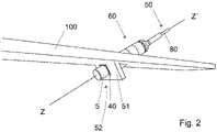
- Figs. 2 to 6 describe a thermal protection sheath 60 forming a sleeve for the protection of a portion of an elongated structural element forming a tensioned cable 50, for example a stay cable.
- the sandwich-like composite thermal insulation system made from the fire protection layers previously described (optionally the first layer 10, the second layer 12, the third layer 14, the fourth layer 16 and optionally the fifth layer 18) protects in a preferred embodiment critical elements of a stay cable in the area where they might become exposed to a fire event.
- a thermal protection sheath 60 formed with said sandwich-like composite thermal insulation system one can obtain a suitable thermal protection of parts of a tensioned cable 50, including guide pipe 55, guide system 70, deviator or damper 72, and other components being part of an anchorage 52 (see Fig.4 to Fig.6 ).
- a thermal protection cap 5 is visible at the left side while it covers an anchorage 52 fixed to a load transfer abutment of the civil engineering structure, for example a blister or panel 51 of the bridge deck 100, and a thermal protection sheath 60 extends the thermal protection of the tensioned cable 50 from the other side of the load transfer member.
- the thermal protection sheath 60 and the thermal protection cap 5 are formed by a sandwich-like composite thermal insulation system.
- the thermal protection sheath 60 contains possibly the first layer 10, second layer 12, third layer 14 and fourth layer 16, as previously described in relation with the thermal protection sheath 1 or 60, and which are superposed, and the thermal protection sheath 60 wraps a length of the running portion of the tensioned cable 50 extending from the anchorage 52.
- the tensioned cable 50 is mounted on a bridge deck 100, through a blister or panel 51 forming a portion of the concrete substrate.
- the anchorage 52 (tensioned cable end) and the thermal protection cap 5 extends under the bridge deck 100.
- the running part of the tensioned cable 50 and the sheath 60 extend above the bridge deck 100.
- the cable anchorage 52 might alternatively also be located above the bridge deck 100 and connected to it by means of a steel or concrete element such as the panel 51 and protruding upwards from the bridge deck 100: in that situation, end portion of the cable 50, thermal protection sheath 60 and cap 5 are upwardly offset with respect to their position in Fig.2 .
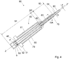
- the thermal protection sheath 60 comprises three portions 61, 62, 63. More precisely, said sheath 60 has three portions comprising a first cylindrical portion 61 with a first diameter for covering the length of an elongated structural element close to an anchorage 52, a second portion 62 shaped as a frustum of a cone and extending from the first cylindrical portion 61 with a reducing diameter, and a third cylindrical portion 63 with a third diameter which is smaller than the first diameter. In some cases, any of the three portions 61, 62, and 63 is omitted if the respective area is not exposed to a fire event.
- the first portion 61 forms an envelope surrounding the length of the tensioned cable 50 extending from the anchorage 52 and housed inside a guide pipe 55 forming a void inside the structure 51.
- the guide pipe is fitted with a flange 55a (see Fig.5 ) to support the weight of portions 62 and 63 and other possible elements of the cable assembly such as guides (such as guide system 70 of Fig.5 ) and dampers (such as damper 72 of Fig.5 ).
- the guide pipe 55 is sized such as to allow transverse movement of the cable 50 and the first portion 61 is dimensioned so as to fit over the flange 55a.
- the first portion 61 has preferably a constant internal diameter.
- the first portion 61 is firmly resting on the concrete panel 51 (slab or abutment).
- the first portion 61 forms an inward flange 66 for connection with the second portion 62.
- An optional rigid cylindrical outer cover 73 for example made of steel, and possibly formed by two assembled half-shells, may provide additional protection and durability for the first portion 61 (see Fig.4 ).
- the composite insulation system forming the first portion 61 comprises four layers which are the second layer 12, the third layer 16, the fourth layer 18 and the fifth layer 20 as previously described. In that case, preferably, the first portion 61 is preferably covered by said outer cover 73.
- the second portion 62 is an envelope surrounding a section of the cable 50 installed with the guide or damping means: the second portion 62 is dimensioned such that it does not impede the guide system 70. This is achieved by providing an annular space 62a between the inner face of the second portion 62 and the outer face of the guide system 70.
- the second portion has a variable internal diameter increasing from the internal diameter of the first portion 61 (first diameter) to the internal diameter of the third portion 63 (third diameter).
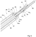
- the guide system 70 can have several possible configurations and functions, such as only bundling the cable 50 and being attached to the cable 50, but free to move relative to the guide pipe 55 (see Fig.6 ), or guiding the cable 50 by being fixed relative to the cable 50 and the guide pipe 55 (not shown) or being part of a rigid or semi-rigid guide or a damper 72 fixed between the cable and the guide pipe 55 (see Fig.5 ). Also an outer rigid shell 64 taking the shape of a frustum of a cone covers the second portion 62 to provide durability and protection of the second portion 62.
- the composite insulation system forming the second portion 62 comprises five layers which are the first layer 10, the second layer 12, the third layer 16, the fourth layer 18 and the fifth layer 20 as previously described. In another preferred embodiment, the composite insulation system forming the second portion 62 comprises four layers which are the second layer 12, the third layer 16, the fourth layer 18 and the fifth layer 20 as previously described.
- the third portion 63 encloses the length of the running portion of the cable 50 by being placed around the outer pipe 80 of the cable 50 in a close or tight manner with or without a nominal gap.
- the diameter of the third portion wrap is hence such that the inner diameter is the same or slightly larger than the outer diameter of the outer face of the cable 50.
- this third portion 63 can have a small or large length, ranging preferably up to 50 meters, and more preferably up to 20 meters and ranging preferably up to 10 meters, notably about from 1 to 10 meters. Important lengths are therefore achieved by subsequent connection of multiple portion units.
- the composite insulation system forming the third portion 63 comprises four layers which are the second layer 12, the third layer 16, the fourth layer 18 and the fifth layer 20 as previously described.
- the third portion 63 is preferably covered by an outer cover 75 (HDPE or steel) possibly formed by a pipe which may provide additional protection and durability for the third portion 63 (see Fig.4 ).
- This optional rigid cylindrical outer cover 75 can also be used in presence of the first layer 10 in the composite insulation system forming the third portion 63.
- the connection between the first portion 61 and the second portion 62 is achieved through an overlapping splice joint 71 (see Fig.5 ). More precisely, the composite insulation system of the first portion 61 and of the second portion 62 both have end portions which are superposed at the interface. To accommodate relative movements between the cable 50 and the guide pipe 55 and therefore also between the first portion 61 and the third portion 63, the second portion 62 is fabricated in a manner to allow for flexibility. This is achieved in a preferred embodiment by providing enough geometrical slack in the shape of the second portion 62. A similar spliced arrangement is used for the connection between the second portion 62 and the third portion 63. Preferably, as can be seen in Figs.
- an insulation support board 65 is placed at the junction of the second portion 62 and of the third portion 63: it supports the outer cover 64 and reduces the passage of heat from this cover 64 to the cable 50.
- the support board 65 rests on a spacer tube which in turn rests either on the guide 70 or the guide pipe flange 55a.
- the total length of the first portion 61 and second portion 62 is equal to or lower to 75% of the total length of the sheath 60.
- At least one portion of the sheath 60 is formed by two half shells assembled together in a reversible manner.
- both second portion 62 and third portion 63 are formed by two half shells.
- Such a configuration, and notably the flexibility of the sandwich-like composite insulation system and materials, allows a possible flexural deformation of the thermal protection sheath 60, and in particular its third portion 63 to follow the variation of sag of the cable 50 due to changes in axial cable force or changes of its deformed alignment due to changing lateral loads, such as wind drag forces, or due to vibrations caused by excitation of the cable due to wind effects or by excitation through coupling with vibrations of the structure caused by fluctuating loads or other external effects.
- Additional flexural deformation of the sheath 60 can be achieved by providing flexible joints between individual elements of the third portion 63.
- the direction of the offset between the first step 76 1 and the second step 76 2 is inversed for the transverse edges of the sheath 1, so that formation of the axial joint 76 is obtained through abutting these two extremities of the adjacent pair of individual elements of the third portion 63 of the sheath 60.
- the shape of these end edges being therefore complementary and able to fit together with contact which provides continuous thickness of the wall for the whole third portion 63. Also, it provides a splice connection for adjacent elements of the third portion 63, therefore preventing thermal passage at the interface of two adjacent elements of the third portion 63.
- the cable 50 remains free to deform longitudinally under varying axial cable loads.
- load variation can be caused for example by changes in bridge traffic loading, temperature and other external loads.
- the composite insulation system according to the invention allows a thermal conductivity lower than or equal to 0.11 W/m.°C at 800°C for a thickness lower than 50 millimeters, and notably a thickness between 20 and 40 millimeters.
- a thermal conductivity at 800°C equal to or less than 0.10 W/m.°C, or even equal to or less than 0.09 W/m.°C can be obtained for the composite insulation system according to the invention.
- a thermal conductivity at 800°C ranging from 0.06 W/m.°C to 0.11 W/m.°C can be obtained for the composite insulation system according to the invention.
- the thermal conductivity performance at other working temperatures reaches also very good results.
- the composite insulation system according to the invention allows a thermal conductivity lower than or equal to 0.01 W/m.°C, lower than or equal to 0.009 W/m.°C and even lower than or equal to 0.0085 W/m.°C, preferably ranging from 0.006 W/m.°C to 0.01 W/m.°C.
- the composite insulation system according to the invention allows a thermal conductivity lower than or equal to 0.022 W/m.°C, lower than or equal to 0.02 W/m.°C and even lower than or equal to 0.018W/m.°C, preferably ranging from 0.011 W/m.°C to 0.022 W/m.°C.
- the composite insulation system according to the invention allows a thermal conductivity lower than or equal to 0.084 W/m.°C, lower than or equal to 0.08 W/m.°C and even lower than or equal to 0.075 W/m.°C, preferably ranging from 0.045 W/m.°C to 0.084 W/m.°C.
- the composite insulation system according to the invention allows a thermal conductivity lower than or equal to 0.17 W/m.°C, and even lower than or equal to 0.15 W/m.°C, preferably ranging from 0.10 W/m.°C to 0.17 W/m.°C.
- W max K ⁇ D kG / m 2 with D the smallest inner diameter of said sheath 60 (in m), W max in kg/m and Factor K between 20 to 30, preferably between 22 to 27, and which can be 25.
- this value for the maximum weight W max per length unit concerns the third portion 63 which therefore has a small weight (about 1 Kg/m to 10 Kg per m) which remains small compared to the self weight of the cable 50 which advantageously not excessively increases the cable sag and hence tension in the cable 50 (if it is supported by the cable).
- any variation of the deformed alignment or sag of the cable 50 will result in rotations at the reference point P between the running length of the cable and elements rigidly connected to the supported or surrounding civil engineering structure such as the guide pipe 55 or the end of the anchorage 52.
- the reference point P corresponds for example to the fixation point of the strand of the cable 50, which is considered to be located at the terminal end face of the anchorage 52 on the left of Fig.4 ).
- Such angular rotations can exceed for example 10mrad, or for example 25mrad and can reach up to 50mrad depending on the length of the cable and the flexibility of the civil engineering structure.
- Any angular rotation ⁇ translates in a relative displacement transverse to the longitudinal direction of the cable between the running length of the cable 50 and the supported or surrounding civil engineering structure in discrete points such as for example at the exit of the guide pipe 55 adjacent to the second portion 62 of the sheath 60 requiring to accommodate large transverse movements by providing for example geometrical slack in the shape of the second portion 62.
- the sheath 60 can accommodate typical flexure of the running part of the cable 50 as well as transverse movements resulting from typical angular rotations ⁇ close to the anchorage 52 between the movable parts attached to the cable 50 and the fixed parts attached to the supported or surrounding civil engineering structure. Also, such flexibility is also advantageous for the cable installation, because it allows movements sufficiently large of the cable 50 equipped with the sheath 60 to have an easy handling.
- this flexibility is such that said sheath 60 (or sheath 1) can be bent so as to define an arc of circle having a radius R of about 2m or more
- said sheath 60 flexibility is such that the third portion 63 can be bent so as to define an arc of circle having a radius R of about 2 m or more (see Fig.6 ).
- said sheath 60 flexibility is such that when the end of the second portion 62 close to the anchorage 52 is fixed, said sheath portion 62 can accommodate a displacement transverse to the longitudinal direction of the cable 50 equivalent to an angular rotation ⁇ of the running part of the cable at the exit of the anchorage of at least 50mrad, following thereby the movement of the cable 50 (see Fig.4 ).
- said sheath 60 (or sheath 1) can accommodate a transverse movement being equal to D, where D is the internal diameter of the sheath 60 (or of sheath 1), or D is the smallest internal diameter of the sheath.
- the sheath 60 forms a thermal protection device 90 which, in terms of flexibility, can be defined as having a fixed part 91 (first portion 61 of the sheath), a flexible part 92 for transverse movement (second portion 62 of the sheath 60) and a flexible part 93 for bending.
- Fig. 4 shows the end part of the anchorage 52 of the cable 50 located on the side of the concrete panel 51 opposite to the running part of the cable 50.
- the end part of the anchorage 52 is fitted with an end cap 53 providing mechanical protection and sealing.
- This end cap 53 is comprised in the fixed part 91.
- a cylindrical thermal protection cap 5 is used to also protect the end part of the anchorage 52 and its cap 53 against fire or other thermal effects.
- the fixed part 91 comprises further this thermal protection cap 5.
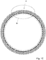
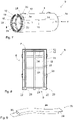
- the cylindrical thermal protection cap 5 forms a sleeve of circular section, open at one end and closed at the other end. Therefore, the cylindrical thermal cap 5 is formed by a cylindrical wall 6 and an end wall 7 both having the same superposed layers forming a sandwich like wall. These stacked layers form a composite insulation system. A large circular opening 8 is therefore formed at the end of the cylindrical thermal protection cap 5, to allow for introduction over the element to be protected.
- the composite insulation system is equivalent to the one described for sheath 60 and composed of five layers, previously mentioned as first layer 10, second layer 12, third layer 16, fourth layer 18 and fifth layer 20, from the outermost layer to the innermost layer of the composite insulation system.
- the fifth layer 20 forms the interface layer between fabric layers forming said composite insulation system and a frame structure 24 with elements 22.
- said frame structure 24 is a metallic frame or a ceramic frame or a combination thereof.
- said frame structure 24 has circular rings placed along the length of the thermal protection cap 5 and following the inner circumference of the thermal protection cap 5.
- said frame structure 24 further comprises sections parallel to each other and extending along the length of the thermal protection cap 5, as illustrated in Fig 4 .
- Fig 8 shows the cross-sectional elevation of a complete thermal protection device for the end part of an elongated structural element at installation, namely said cylindrical thermal protection cap 5 and a closure band 28 able to be strapped around the end opening 8 of said cylindrical thermal protection cap 5 .
- the metallic frame 24 is longer than the cylindrical wall of the composite insulation system (layers 10, 12, 16, 18 and 20). In this way, access is provided to the flat-angle brackets 22 for tools used for the attachment of the metallic frame 24.
- the flat-angle brackets 22 are manufactured with holes to allow for mechanical fixation (for instance with bolts).
- said cylindrical thermal protection cap 5 is used with a closure band 28 able to be strapped around the opening 8 of said cylindrical thermal protection cap 5.
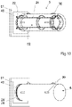
- Fig. 9 illustrates a removable band 28 that fills the void at the end of the thermal protection device post-installation. More precisely, the space formed between the open end of the sleeve (formed by the thermal composition system) and the extremities of the frame (connection elements 22) is closed post-installation with the closure band 28.
- two ribbon sections 29 are placed at the two ends of the removable band 28 able to be connected together by fixation means (loops and hooks, or other means such as Velcro system (trademark)).
- fixation means loops and hooks, or other means such as Velcro system (trademark)
- metallic band 26 Fig 3
- a tightening mechanism to hold the removable band 28 around the thermal protection cap 5 in place, as a strapping band.
- band 28 allows for ease of access for the fixation of the thermal protection cap 5, as the flat-angle brackets 22 are not covered by the composite insulation system or any other elements.
- Handles 30 are preferably used at the outer surface of the thermal protection cap 5, over the first layer 10, to facilitate the handling of the thermal protection cap 5. Handles are interlayer stitched into layers 10 and 12 for robustness.
- the thermal protection device for the end part of an elongated structural element comprises said cylindrical thermal protection cap 5, and preferably comprises further an insulation board 40 with a machined hole.
- Said insulation board 40 is able to be placed against the opening 8 of said cylindrical thermal protection cap 5, with the hole facing said opening 8.
- the metallic frame 24 is attached to the insulation board 40.
- the insulation board 40 is a calcium silicate board.
- Such an insulation board 40 is precision machined and is mechanically fixed (for instance bolted) to the protected structure, i.e. the concrete panel 51 from which the anchorage 52 extends towards the right in . Figs.10 and 11 .
- the metallic frame 24 with the layers 20, 18 and 16 already fixed form a first inner assembly.
- the one-piece cover formed by the first layer 10 and the second layer 12 is engaged around the previously attached first assembly: the cover (first layer 10 and second layer 12) forming a standalone sleeve or outer assembly that is slid over the third layer 16.
- the entire assembly consisting of the metallic frame and layers 20, 18, 16, 12 and 10 is then installed over the end of the elongated structural element to be protected.
- the thermal protection cap 5 can range in sizes depending on the required dimensions of the application.
- the thermal protection device has an outer diameter between 200 millimetres and 1000 millimetres, notably about 500 millimetres, and a length of about 500 millimetres to 2000 millimetres or more.
- the thermal protection cap 5 can have different shapes depending on the shape of the anchorage 40 and its end cap 52 to be protected, the available space at the location of the anchorage and/or depending on the specific layers used in the composite insulation system of the cylindrical thermal protection cap.
- the first to fifth layers 10, 12, 14, 16, 18 and 20 have a cylindrical wall with a circular section but other section's shape are possible, such as oval, elliptic, rectangular, square, other quadrilateral or more generally other polygonal shapes.
- Such a configuration allows the use of the thermal protection sheath 60 and of the thermal protection cap 5 on newly installed and already existing civil engineering structures for retrofitting of the equipment.
- the thermal protection sheath 60 and the optional thermal protection cap 5 form a thermal protection device 90 providing a solution for the high-level thermal protection of a length (running part and the end part) of the tensioned cable 50 (or any other structural elongated element) running from the anchorage 52.
- This thermal protection sheath 60 can efficiently protect the portion of the tensioned cable 50 around which it is wrapped by resisting temperatures of 600°C or more (up to 800°C, 1000°C and in some cases 1200°C) for a time period of more than 30 min, namely up to more than 90 min.
- thermal protection sheath 60 provides a low weight solution allowing for a reduced extra weight on the tensioned cable 50, which limits the additional load exerted on the tensioned cable 50 and the overall construction, and also permits the maintenance to parts of the tensioned cable 50 requiring to be controlled since the portions of the thermal protection sheath 60 which need to be taken off can be manual handled, and moreover this thermal protection sheath 60 does not hinder the free movement of the cable by its flexibility.
- an elongated structural device comprising an elongated structural element such as a tensioned cable 50 with at least one anchorage part 52 (including possibly two anchorage parts) at the end(s) of the cable 50, and at least one thermal protection sheath 60, wherein said cylindrical thermal protection sheath 60 covers a length of the cable 50 extending from the anchorage part 52.
- an elongated structural element such as a tensioned cable 50 with at least one anchorage part 52 (including possibly two anchorage parts) at the end(s) of the cable 50, and at least one thermal protection sheath 60, wherein said cylindrical thermal protection sheath 60 covers a length of the cable 50 extending from the anchorage part 52.
- the elongated structural element is an external post-tensioned cable or a stay cable.
- a cylindrical thermal protection sheath 60 as previously described in a civil engineering structure with elongated structural elements having its ends fixed close to or to one anchorage 52, wherein said thermal protection sheath 60 wraps a length of said elongated structural elements close to at least said anchorage 52.
- a thermal protection sheath 60 is obtained a civil engineering structure, wherein the said cylindrical protection sheath 60 is able to accommodate transverse movements at the transition point between the running length of said elongated structural element (such as the cable 50) and elements rigidly connected to the supported or surrounding civil engineering structure equivalent to angular rotation ⁇ at the anchorage 52 (reference point P) up to at least 50mrad.
- the composite insulation system includes at least:
- first and second layers are stitched together.
- first and second layers are stitched together as a pair.
- the stitching between the first and second layers is bi-axially inter-stitched to form a robust outer envelope for the thermal protection cap.
- the first, second and third layers are all inter-stitched.
- said composite insulation system further comprises a fourth layer covering the inner side of the third layer and comprising a micro-porous thermal insulation material.
- Such a fourth layer has a low thermal conductivity thus forming a high temperature thermal insulation barrier, while adding structural integrity to the composite insulation system forming the cylindrical thermal protection cap.
- this fourth layer is a flexible micro-porous layer.
- this fourth layer comprises particles.
- said composite insulation system further comprises a fifth layer covering the inner side of the fourth layer.
- this fifth layer is attached to the fourth layer.
- this fifth layer comprises a structural layer.
- Such a fifth layer forms a durable protection layer, which provides additional protection to the fourth layer, notably mechanical protection during the handling of the cylindrical thermal protection cap.
- the fifth layer is stitched to the fourth layer.
- said cylindrical thermal protection cap may further comprises a frame placed within said composite insulation system and attached to said composite insulation system.
- this frame is a metallic frame.
- this frame is made out of ceramic material or of composite materials.
- Such a frame is notably required to stabilize the mechanical integrity of the sandwich forming the composite insulation system, in particular for large size caps for which the flexibility of the composite insulation system leads to an unstable shape for the cap in applications of particular orientations.
- the thermal composite layers of the composite insulation system are permanently fixed to the rigid frame, the generic structural fitment providing lasting rigidity.
- a frame also facilitates the installation and fixing of the cylindrical thermal protection cap onto the elongated element or the end of the elongated element to be protected.
- the invention also relates to the use of such a thermal protection cap for the thermal protection of an elongated structural element.
- an elongated structural element serves for instance as an element providing the strength and mechanical load resistance to a civil engineering structure.
- Such a thermal protection cap according to the invention can serve for the thermal protection of the end part of any elongated or cylindrical load bearing structure or any cylindrical bearing member including any tensile member (including a post-tensioning tendons and stay cable) and their anchorages.
- the invention relates to the use of such a thermal protection cap for thermal protection of the end part of a post-tensioning cable anchorage or of a stay cable anchorage or of a ground anchor.
- the thermal protection cap 5 can cover an anchor element of a tensioned cable, or more generally an elongated tensile element, which's end part is embedded in a concrete structure.
- Said elongated tensile element can be for example a pre-stressing cable used to apply a pre-compression force to said concrete structure in order to control undesirable tensile stresses occurring otherwise in the concrete structure under the application of external loads or deformation.
- said concrete structure can be for example a containment structure with a circular shape in plan view used to contain matter exerting a positive internal pressure to the containment structure and hence resulting in tensile hoop stresses which are in turn compensated by applying a pre-compression to the concrete structure by means of an embedded pre-stressing cable.
- a containment structure being for example a storage tank for liquefied natural gas or a part of the containment vessel in nuclear power plants.
- thermal protection caps 5 it is hence desirable for such thermal protection caps 5 to be light weight to allow their manual handling.
- the thermal protection cap is required for example to protect the anchorages against fires caused during maintenance interventions involving electrical equipment, welding or other heat sources which can develop quickly very high temperatures due to the confined conditions and the possible presence of hydrocarbons in the form of fuel, greases or other products used during maintenance interventions.
- the thermal protection cap 5 covers an anchor element of a tensioned cable, or more generally an elongated tensile element, which's end part is embedded in soil and in a concrete element covering a portion of the soil.
- This arrangement forms a ground anchor.
- the ground anchor is on one end anchored in the soil or rock, for example by means of mechanical interlocking or bond through a cementitious injection, and its anchor element on the opposite end is resting against a concrete structure.
- This arrangement allows to pre-stress the ground anchor against the structure and the movement of the structure is hence restrained and controlled by the introduced anchoring force. Due to the consolidation or movement of the soil such ground anchors require regular interventions at the anchor element for the purpose of inspection or measurement of remaining anchor force.
- the thermal protection cap 5 must hence be lightweight in order to allow its manual handling during these interventions in locations which are typically exposed and difficult to access due to their height above ground. Thermal protection caps 5 are typically required where the anchor elements are located adjacent to roads, railroads, navigation channels or other traffic routes used by vehicles, ships or trains carrying large amounts of hydrocarbon in the form of fuel or payload in order to protect the highly loaded anchor elements against the effects of accidental or wilfully caused fires.
- thermal protection cap 5 allows the use of the thermal protection cap 5 according to the invention on already existing civil engineering structures for retrofitting of the equipment.
- the cylindrical thermal protection cap 5 also serves for protection against other thermal source such as environmental impacts: direct sunlight exposure, any change in ambient temperature from other sources than fire.
- a cylindrical fire insulating cap for the thermal protection of end terminations of structural elements, and notably for end anchorages of post-tensioning tendons, stay cables or ground anchors and the like.
- Such a cap forms a cover to be installed over an anchorage/pipe, notably an anchorage end or a pipe end.
- This cap can serve in particular as thermal protection for the end of any structural elongated element made from high tensile steel or other high tensile material.
Description
- The present invention concerns an insulation system arrangement for the thermal protection of elongated structural elements. For instance the present invention concerns the thermal protection of cylindrical structures including cylindrical load bearing structures, tensile members and their anchorage components or tensioned cables found in external post-tensioning tendons or stay cables including their end anchorages.
- Such elongated structural elements, and in particular such tensile elements, typically use high strength material, for example high strength cold-drawn steel, to allow for the transfer of concentrated forces through lightweight elements having small cross sections, notably used for the transfer of forces in bridges, buildings, special pressure containment structures, retaining walls and other structures built primarily of concrete or steel. In many cases these tensile elements are pre-tensioned in order to apply a significant pre-load, also called pre-stress, to the surrounding structure.
- Said invention relates to a cylindrical sheath for the thermal protection of elongated structural elements, and notably for post-tensioning tendons, stay cables and the like. Such a sheath forms a sleeve to be fitted around a running portion of a cable, a tendon or a pipe. More generally, this sheath can serve as thermal protection for a length of any structural elongated element made from high tensile steel or other high tensile strength materials susceptible to thermal damage. Said sheath can further be adapted in shape such as to also provide protection for zones where the running portion of a cable penetrates through members of the surrounding or supported structure. Said sheath can be combined with a cylindrical cap to protect the end terminations of such cables.
- Said invention also relates to a cylindrical cap for the thermal protection of end terminations of structural elements, and notably for end anchorages of post-tensioning tendons, stay cables or ground anchors and the like. Such a cap forms a cover to be installed over an anchorage/pipe, notably an anchorage end or a pipe end. This cap can serve in particular as thermal protection for the end of any structural elongated element made from high tensile strength steel or other high tensile strength material.
- More precisely the present invention concerns the protection against extreme thermal loading scenarios that result for example from hydrocarbon fires. Elongated structural elements on many different types of structures can be exposed to such fire events as a result of accidents or wilfully caused, for example vehicle or ship impact or spills with the subsequent burning of fuel, burning of hydrocarbon materials used in construction or maintenance operations or other unplanned events during the lifetime of the structure involving hydrocarbon materials in a solid, liquid or gas state. Such extreme loading scenarios typically result in temperatures exceeding 600°C, and in some cases exceeding 1000°C in confined or unconfined environments with durations which can well exceed 30 minutes, and sometimes in excess of 60 or even 90 minutes.
- End anchorages of such structural elongated elements conventionally rely on mechanical anchorage by direct bearing or friction or bonding between different materials to secure highly stressed elements at their end to the surrounding structure. These end anchorages can either be directly exposed to a fire event or can experience excessive heating when a fire event occurs close to the running length of the cable and the cable acts subsequently as a heat conductor.
- Such end anchorages participate on satisfying general loading scenarios of the structural elements. When subject to elevated temperatures the relaxation percentage of high tensile strength materials typically increases and their strength decreases. Cold-drawn high tensile strength steel is particularly affected by this phenomenon as the strength gain achieved by cold forming the steel during its manufacturing is largely reversed by heating above a critical temperature, consequently resulting in a loss of pre-stressing forces and a general reduction in structural resistance. Furthermore excessive heating can lead to slippage or failure of the stressed element in the end anchorage. Surrounding concrete or other structural or protective layers along a member's span often protect(s) the high strength steel from such an undesirable increase in temperature, reducing the likelihood of extensive thermal relaxation and strength loss. End anchorage arrangements, as well as tensile members external to a structure, however remain susceptible as the anchorages are typically exposed to the heightened temperatures during an extreme thermal event.
- Subsequently, high thermal loading on such highly stressed elongated structural elements, including their end terminations, increases the likelihood of steel relaxation, tendon failure or anchorage slippage or failure occurring, resulting in an overall loss of pre-stressing force or ultimate resistance. Due to the surrounding concrete and developed bond between the high tensile steel tendons, made of strands and wires, the consequences of thermal loading in conventional post-tensioned cables internal to a concrete or other structure is reduced. External cables however, in particular post-tensioning cables external to the structure or stay cables, remain highly susceptible to thermal loading due to being exposed during an external fire event. The risk of steel relaxation, tendon failure or anchorage slippage as a direct result of an external fire event is therefore significantly higher for an external post-tensioning cable or a stay cable. Due to the concentrated manner in which such cables transfer loads and the low level of redundancy, the structural safety of civil engineering structures containing external post-tensioning tendons, cable stays or other exposed cables, such as bridges, beams, girders, cable supported towers or masts or suspended roof systems can be severely impacted by the loss of a cable in a fire event.
- The running part of elongated structural members such as external post-tensioning cables and in particular stay cables is free to move under various effects such as changes in longitudinal elongation, variation of cable sag due to changes in axial cable force or changes of its deformed alignment due to changing lateral loads, such as wind drag forces, or due to vibrations caused by excitation of the cable due to wind effects or by excitation through coupling with vibrations of the structure caused by fluctuating loads or other external effects. As a result, the geometrical curve which the running part of the cable adopts can vary and relatively large movements can occur relative to the surrounding or supported structure and the cable's end anchorage. These movements can remain unrestrained or if considered detrimental to the performance of the cable (bending at the anchorage, fatigue, damage by mechanical impact between cable and surrounding structure, unacceptable reduction of comfort for the user of the structure) controlled or limited by the use of guides, stoppers or dampers fitted between the running part of the cable and the surrounding structure. It is known to dampen such relative movements by viscoelastic means or means acting by rubbing or friction. Such damping means are connected to the cable at a certain distance from the end anchorage in order to develop the required damping performance.
- Given the flexible nature of such cables and the need to accommodate large movements, any thermal protection sheath provided for the running length of the cable must be able to adopt its shape to the changing sag line of the cable as well as allowing for relatively large local displacements at the interface between the thermal protection elements and the surrounding structure. Furthermore, the self weight of the sheath must remain small compared to the self weight of the cable if it is supported by the cable in order not to excessively increase the cable sag.
- Given the need to fit guides, stoppers or dampers to limit the relative movements between the cable and the surrounding or supported structure, any thermal protection sheath needs to be easy to remove for the purpose of inspection, maintenance and possible replacement of such devices during the lifetime of the structure. The sheath must therefore be lightweight and modular.
- Such stay cables typically support bridge decks, suspended roof structures or tall masts and towers which are all exposed to horizontal wind loads. The horizontal loads generated by wind drag on the stay cables can be a substantial part of the total horizontal loading on the structure (exceeding in some
cases 50% of the total horizontal wind load). Hence it is of utmost importance to minimize the wind drag by limiting the outer diameter of the stay cables and fitting them with aerodynamically optimized surfaces. Any thermal protection sheath fitted to the cable must hence remain small in diameter. - Contrary to stay cables and some other types of external cables which are unbonded from the structure, the presence of grout encapsulation in bonded post-tensioning tendons tends to reduce the consequences of localised thermal loading on the high tensile steel tendon made of strands or wires due to the developed bond between the strands/wires and surrounding concrete. However, the consequences of anchorage movement and relaxation on unbonded tendons tends to be more severe due to an overall loss of member integrity as the ability to transfer forces between the tendon and concrete through the developed grout bond is removed.
- Such negative effects are always sensitive for maintaining the safety of civil engineering structures containing post-tensioning tendons, cable stays or ground anchors, such as bridges, suspended roof systems and retaining walls, with the safety criteria being even more demanding in the case of post-tensioning cables and post-tensioning end-anchorage present in nuclear facilities and containment structures.
- Many kinds of piping thermal insulation methods and systems are known. However such systems are specifically developed to reduce the exothermic flow from the covered element, whereas said invention is specifically designed to protect the covered element from an external thermal loading source, such as fire.
- Furthermore, the thermal insulating properties of these conventional insulation materials do not suffice in the protection of structural elements during extreme thermal loading scenarios that typically exceed temperatures of 1000°C for exposure durations of 30 minutes or more.
- Alternatively, surface applied intumescent products form a protective coating for structural elements such that when exposed to a fire load for a small exposure interval, satisfactory element protection is provided. However, such methods and materials do not provide extended protection as they typically fail to reduce the conduction of thermal energy into the structural element during extended high temperature exposure intervals. Furthermore they are susceptible to mechanical damage as they cannot be covered by additional protective layers due to the need to allow their free expansion to achieve the protective function.
-
WO2007093703 relates to a fire protection device for a stay cable formed by two blankets wrapped around the cable, and overlapping each other. Also, an outer shell is covering the stacked blankets, this outer shell being made of high density polyethylene (HDPE). Such a fire protection device is not suitable for a high level thermal protection unless using an increased thickness of insulating material, which leads to an increased and undesirable weight and great difficulties in installation especially in the interface area where the cable penetrates the supported structure as well as any guides, stoppers or dampers that might have to be fitted. -
WO2012052796 provides a thermally insulating rigid tube arranged around a stay cable with a thermally insulating material having a minimum thickness requiring an air channel between the insulating tube and the cable and a significant height difference to achieve heat evacuation by convection. Such an arrangement is rigid and cannot therefore accommodate the flexure which occurs along the running length of the cable under varying cable sag or the large relative displacements at the interface where the cable penetrates the supported structure during normal working conditions. Such an arrangement can only ensure the required freedom of movement of the cable by providing a very large air gap between the rigid tube and the cable resulting in a significant increase of cable diameter having an undesirable impact on the visual appearance of the cable, increasing the required lateral clearance to adjacent parts of the structure and increasing the wind drag of the cable. - It is an aim of the present invention to provide a cylindrical thermal protection sheath and a thermal protection cap which mitigates or obviates at least some of the above-mentioned disadvantages.
- This aim is achieved by the solution proposed in
claim 1. - Preferably, for a thickness lower than 50 millimetres, said sandwich-like composite insulation system has a thermal conductivity at 800°C lower than or equal to 0.10 W/m.°C and preferably lower than or equal to 0.09 W/m.°C. Such a thermal protection sheath forms a thin multi-layered composite construction developed for the extreme extended thermal protection of length of elongated structural elements, such as external post-tensioning cables, cable stays, roof suspension elements, steel profiles and pipe ends, and in particular post-tensioning tendons and cable stay end anchorages.
- The invention also relates to a thermal protection device comprising the cylindrical thermal protection sheath and a cylindrical thermal protection cap which forms an extreme extended thermal protection of end terminations of elongated structural elements.
- The invention also relates to an elongated structural device comprising a tensioned cable (or any other elongated structural element) with a running part and at least one anchorage part at the end of the cable, and at least one thermal protection sheath as previously described, wherein said cylindrical thermal protection sheath covers a length of the running cable extending from the anchorage part.
Optionally, this elongated structural device further comprises an outer cover enclosing the thermal protection sheath. - Another aspect of the invention relates to a cylindrical thermal protection cap with a single sided closed end, said cap comprising a cylindrical wall and an end wall, said cylindrical wall defining an opening for the introduction of the end of an elongated element, said cylindrical wall and said end wall comprising a composite insulation system including at least:
- an outer first layer having a protective outer side,
- a second layer covering the inner side of said outer first layer, said second layer being a fabric made from filament and reinforced yarns, and
- a third layer covering the inner side of the second layer and comprising a thermal insulation layer essentially made from fibers,
- Such a cylindrical cap forms a thermal insulating protection cap comprising of a multi-layered composite construction developed for the extreme extended thermal protection of end terminations of elongated structural elements, such as post-tensioning cables, cable stays, ground anchors, steel profiles and pipe ends, and in particular post-tensioning tendons and cable stay end anchorages.
- The present invention comprises a durable outer first layer having a protective outer side, which is a metallic, metallic-like or non-metallic outer side, such as an aluminized fabric or any other reflective layer, for mechanical protection of the composite construction and increased heat reflection of thermal radiation. This outer first layer is preferably fixed with inter-layered stitching to a series of specifically arranged thermal insulating materials. The thermal insulation materials preferably consist of both semi-rigid and formable materials which enable the composite cap to form a general cylindrical shape for generic size fabrication.
- The second layer and third layer each form a composite insulating layer, are preferably inter-stitched, and are overlapped with respect to each other in order to provide extensive coverage of the protected system (elongated element such as a tensioned cable end anchorage) and increase overall system efficacy. Each composite layer spans the circumference of the cylindrical protection cap and consists of various potential insulating materials, of low thermal conductivity, in order to provide both added strength and reduced thermal conduction. For instance, the third layer comprises numerous thermal insulating materials of both the fibrous and porous types.
- Other provisions according to the invention are presented herein after in relation with some possible embodiments.
- The invention will be better understood with the aid of the description of an embodiment given by way of example and illustrated by the figures, in which:
-
Fig. 1A shows an isometric view of an embodiment of a section of a cylindrical thermal protection sheath according to the invention. -
Fig. 1B shows an isometric view of an alternative embodiment of the cylindrical thermal protection sheath ofFig. 1A , -
Figs. 1C and1D respectively show an end overview and a detail of the longitudinal joint of the alternative embodiment ofFig.1B -
Fig.2 is a perspective view of a thermal protection device, with a thermal protection sheath according to the invention, mounted on a stay cable system of a civil engineering structure. -
Fig.3 is a perspective view of the stay cable system ofFig.2 with a thermal protection device including a thermal protection cap mounted on the anchorage and a thermal protection sheath according to the invention mounted on the length of the running portion extending from the anchorage and also covering the interface area between the civil engineering structure and the cable. -
Fig.4 is a longitudinal section of the stay cable system with the thermal protection device ofFig.3 . -
Fig.4A shows the section of the adjacent elements of the third portion of the thermal protection sheath according direction IVA-IVA ofFig.4 . -
Fig.5 and6 are enlarged partial views ofFig 4 . -
Fig. 7 shows an isometric view of an embodiment of a cylindrical thermal protection cap. -
Fig. 8 is a longitudinal sectional view of the cylindrical thermal protection cap ofFig. 7 . -
Fig. 9 is a perspective view of a removable closure band used for installation of the cylindrical thermal protection cap ofFig. 7 and 8 . -
Fig.10 is a perspective view of a transparent cylindrical thermal protection cap mounted on a stay cable anchorage. -
Fig.11 is a perspective view of a thermal protection cap mounted on a stay cable anchorage, after complete installation. - As shown on the embodiment of
Fig. 1A thethermal protection sheath 1 forms a sleeve of tubular shape, open at both ends. Therefore, the tubularthermal protection sheath 1 is formed by awall 2 consisting of layers forming a sandwich. These layers form a composite insulation system. Preferably, the thickness and the dimensions (including the diameters when the sheath is formed) of the individual layers of thermal insulation materials are such that there is contact between the adjacent layers. In such a configuration, the layers are stacked in the sandwich like structure of the composite insulation system. A largecircular opening 3 is therefore formed at both ends of the tubularthermal protection sheath 1, to allow for the introduction over theelement 80 to be protected. Thesheath 1 has a tubular shape with a section which can be circular or non-circular (for instance a shape such as oval, elliptic, rectangular, square, other quadrilateral or more generally other polygonal shapes). - In another embodiment shown on
Fig.1B the tubularthermal protection sheath 1 is further fitted with one or severallongitudinal joints 4 allowing opening of the tubular section and hence retrofitting over an already installed element to be protected. In order to not increase the overall diameter of the thermal protection system at thelongitudinal joint 4, the materials forming the overlap are preferably staggered, thus resulting in a continuous material thickness around the circumference of the system. For instance as shown inFig.1C andFig.1D , along the joint 4, and for the two longitudinal edges of thesheath 1, which extends in the direction of thecable 50,outer layers first step 41 andinner layers second step 42, offset with respect to thefirst step 41. The direction of the offset between thefirst step 41 and thesecond step 42 is inversed for the longitudinal edges of thesheath 1, so that formation of thelongitudinal joint 4 is obtained through abutting these two longitudinal edges of thesheath 1 which shape are therefore complementary and can fit together with contact. - In the shown embodiment the composite insulation system is composed of five layers, hereinafter mentioned as
first layer 10,second layer 12,third layer 16,fourth layer 18 andfifth layer 20, from the outermost layer to the innermost layer of the composite insulation system. - The
first layer 10 is a protective layer formed of metallic, metallic-like or non-metallic material being made preferably of a reflecting material such as aluminized reflective fabric. More generally, thisfirst layer 10 has preferably a metallic-like outer face reflecting thermal energy. This firstouter layer 10 provides the external layering of said composite insulation system and of said cylindrical thermal protection sheath 1: it forms an outer cover. Preferably, this is a protective outer cover providing protection to the rest of thesheath 1, notably against mechanical damages (such as etching or wear) and/or atmospheric exposure (such as ultraviolet rays protection). To have the shape of a sleeve with two open ends, as for other layers, the first (outer)layer 10 is for instance formed by a rectangular piece attached together by stitching 14 to form a cover that encompasses the entirety of said sheath external area. - This
first layer 10, such as an aluminized reflective fabric, serves in an embodiment to reflect thermal radiation, thus reducing thermal energy input into subsequent internal layers of the composite insulation system. Thisfirst layer 10 also serves as thermal insulation. Being the exposed layer of thethermal protection sheath 1, thefirst layer 10 is preferably durable, water resistant and has a high tear resistance. - Being susceptible to the environment and exposed to handling during installation, it is preferable that the
yarn stitching 14 is of a double stitched weave to provide system robustness. Also as a preferred composition of the yarn material of thestitching 14, one can choose stainless steel or other high temperature material such as glass fibre or Kevlar based fibre, or similar high-strength, high temperature materials, or any mixture thereof. - In some cases, the
first layer 10 can be omitted: this can particularly occur when another outer element covers, and therefore protects, the composite insulation system. For instance an external protection can be provided by other means, i.e. for instance an outer pipe (not illustrated inFigs.1A and 1B ) wrapping thethermal protection sheath 1, which outer pipe can be a HDPE pipe or a steel pipe. - The
second layer 12 forms the layer below the first layer 10 (or thissecond layer 12 constitutes a first outer layer when there is no layer 10). Thesecond layer 12 is covering the inner side surface of thefirst layer 10. Thissecond layer 12 is placed directly against the inner side of thefirst layer 10. Preferably, thesecond layer 12 is bi-axially inter-stitched to thefirst layer 10 withstitching 14. Thereby, the first andsecond layers tubular protection sheath 1. More precisely, thefirst layer 10 is formed by the above-mentioned rectangular piece with two ends which overlap at the circumference interface and are stitched. Therefore thefirst layer 10 is individually stitched withstitching 14. Also, thesecond layer 12 has a layout analogous to that of thefirst layer 10, the circumferential position of the overlapping ends of the rectangular piece for thesecond layer 12 being staggered with respect to the circumferential position of the overlapping ends of the rectangular piece of thefirst layer 10. Thefirst layer 10 and thesecond layer 12 are set such that the stitched connections are staggered providing continuous cover outside or inside the respective stitching. Thestitching 14 previously mentioned is made with a thermalresistant thread 15. - According to the invention, the
second layer 12 is a fabric consisting of filaments and yarns. These yarns can be reinforced yarns: they serve to reinforce the filaments of the fabric. Therefore, thesecond layer 12 is essentially a primary continuous filament fabric. Preferably, the fabric is a high strength insulation fabric. Also, preferably, the fabric is a high temperature resistant fabric. Consequently, thesecond layer 12 brings cohesion within the composite insulation system. - Preferably, said filaments primarily consist of fabric, preferably mineral fabric, for instance a vermiculite fabric. This
second layer 12 serves as a high temperature reinforced fabric for added thermal protection and added overall strength to thethermal protection sheath 1. Thesecond layer 12 contributes to the structural integrity of the composite insulation system. - Facing the inner side of said
second layer 12 is placed thethird layer 16 made of or mainly formed by a thermal insulation layer which is essentially made from fibers. These fibers are preferably formed by mineral materials. Preferably, said fibers of saidthird layer 16 are made from any of the following materials: ceramic, glass or other mineral material. Said thermal insulation layer is therefore preferably ceramic wool, a glass wool or any similar material. Thisthird layer 16 preferably forms a thermal wool insulation layer, with fibers which may be of a mineral or glass composition with a total bulk density relative to the level of thermal protection required. Thethird layer 16 is covering all the inner side surface of thesecond layer 12. Thisthird layer 16 is placed directly against the inner side of thesecond layer 12. - In an embodiment, the third layer is formed by a fibrous ceramic wool that enhances thermal insulation properties with a low thermal conductivity.
- In a preferred embodiment, said third layer 16 has a thermal conductivity at 200°C equal to or lower than 0.08 W/m.°C , and preferably equal to or lower than 0.06 W/m.°C at 200°C . In a preferred embodiment, said third layer 16 has a thermal conductivity at 200°C comprised between 0.04 and 0.07 W/m°C. Said third layer 16 has preferably a thermal conductivity at 400°C equal to or lower than 0.15 W/m.°C at 400°C , and preferably equal to or lower than 0.1 W/m°C. In a preferred embodiment, said third layer 16 has a thermal conductivity at 400°C comprised between 0.05 and 0.15 W/m°C. Said third layer 16 has preferably a thermal conductivity at 800°C equal to or lower than 0.3 W/m, and preferably equal to or lower than 0.2 W/m.°C. In a preferred embodiment, said third layer 16 has a thermal conductivity at 800°C comprised between 0.15 and 0.3 W/m°C. Said third layer 16 has preferably a thermal conductivity at 1000°C equal to or lower than 0.5 W/m. °C, and preferably equal to or lower than 0.3 W/m.°C. In a preferred embodiment, said third layer 16 has a thermal conductivity at 1000°C comprised between 0.2 and 0.5 W/m°C.
- In an embodiment, said
third layer 16 comprises an envelope defining separate compartments filled with said fibers. For instance, said compartments are cross-stitched pockets. This pillowing of thethird layer 16 contributes to durability, and allows the insulation of this third layer to remain more rigid as to prevent folding or wrinkling during handling and installation of thethermal protection sheath 1. - Preferably, the composite insulation system comprises a
fourth layer 18 covering the inner side of thethird layer 16, with a micro-porous thermal insulation material. This micro-porous thermal insulation material, such as micro-porous calcium-silicate material, forms a high temperature thermal insulation barrier. - Said
fourth layer 18 has preferably a thermal conductivity at 400°C equal to or lower than 0.035 W/m.°C, and preferably equal to or lower than 0.03 W/m.°C. In a preferred embodiment, saidfourth layer 18 has a thermal conductivity at 400°C comprised between 0.025 and 0.035 W/m.°C. Saidfourth layer 18 has preferably a thermal conductivity at 600°C equal to or lower than 0.05 W/m.°C, and preferably equal to or lower than 0.04 W/m.°C. In a preferred embodiment, saidfourth layer 18 has a thermal conductivity at 600°C comprised between 0.035 and 0.05 W/m°C. Saidfourth layer 18 has preferably a thermal conductivity at 800°C lower than or equal to 0.1 W/m.°C, and preferably equal to or lower than 0.07 W/m.°C . In a preferred embodiment, saidfourth layer 18 has a thermal conductivity at 800°C comprised between 0.04 and 0.1 W/m°C. - This
fourth layer 18 is placed directly against the inner side of thethird layer 16. Thefourth layer 18 is covering all the inner side surface of thethird layer 16. - In an embodiment, said
fourth layer 18 comprises an envelope defining separate compartments filled with said micro-porous thermal insulation material. For instance, said compartments are cross-stitched pockets of a predefined size based on the dimensional requirements of thethermal protection sheath 1. - In an embodiment, said micro-porous thermal insulation material comprises a silica and/or calcium silicate and/or alumina silicate. Preferably, said micro-porous thermal insulation material comprises pyrogenic silica.
- In an embodiment, said micro-porous thermal insulation material comprises particles. Such particles are preferably made of or essentially made of silica and/or calcium silicate and/or alumina.
- In an embodiment, said composite insulation system is hydrophobic. In an embodiment, said
fourth layer 18 is hydrophobic. - The
third layer 16 forms a malleable panel at the interspace between thefourth layer 18 and thesecond layer 12. - Preferably, said
third layer 16 and saidfourth layer 18 are attached to each other, for instance byinterlayer stitching 14. Depending on the total size of saidthermal protection sheath 1, it may be necessary to use multiple panels for both thethird layer 16 andfourth layer 18, whereby overlapping of the edges of these panels is required at several locations on the circumference interface of eachrespective layer Fig.1 results. - A staggered construction technique is implemented for cross-connection of the fabric layers to envelope the circumference interface as well as being staggered between subsequent layers. Such a method is preferred to eliminate the likelihood of a thermal passage forming between
stacked layers stacked layers - As shown in
Fig 1 , in an embodiment, afifth layer 20 is used as an inner layer in the composite insulation system. Such afifth layer 20 is placed against the inner side of thefourth layer 18. Such afifth layer 20 is a durable layer. Preferably, saidfifth layer 20 comprises a glass fabric. Suchfifth layer 20 provides necessary protection of saidfourth layer 18 as manufacturing, handling and installation of the sheath can result in structural layer damage. - In an embodiment the
fifth layer 20 forms the interface layer between fabric layers forming said composite insulation system and apipe 80. Preferably, saidpipe 80 is made of a thermoplastic material, for example a polyethylene. In an embodiment, saidpipe 80 provides the outer enclosure of a hightensile steel cable 50 for example a stay cable, for which it provides the necessary installation space and mechanical protection. Thecable 50 can be either a solid element or made up of a group of parallel or stranded wires or groups of strands made of wires helically wound around a core wire. In that case, saidpipe 80 is placed between said running part of thecable 50 and thethermal protection sheath 1 as shown inFigs 1A and 1B . In another embodiment saidpipe 80 is an integral part of the stay cable, for example by being extruded onto the pre-fabricated stay cable during its fabrication or with a space between saidpipe 80 and thecable 50, such space being filled with an injection material, for example grease, wax or cement grout. In another embodiment where it is not necessary to provide an installation space saidpipe 80 can be omitted and thefifth layer 20 is directly adjacent to thecable 50. - In an embodiment, the composite insulation system of the thermal protection sheath 1 (or of the
thermal protection cap 5 described below) comprises at least four thermal insulating layers with at least one layer forming an outer layer and comprising a reflective fabric, one layer comprising a high strength thermal fabric, one layer comprising a fibrous wool based thermal insulation layer and one layer comprising powder filled flexible pocket panels. - In another embodiment, the composite insulation system of the
thermal protection sheath 1 comprises at least three thermal insulating layers with at least one layer comprising a high strength thermal fabric, one layer comprising a fibrous wool based thermal insulation layer and one layer comprising powder filled flexible pocket panels. - Such a
thermal protection sheath 1 has been tested according to the ISO 834 (1975) "Fire Resistance Tests-Elements of Building Construction". The ISO 834:1975 standard establishes the resistance of building components subjected to standard thermal loading conditions. A thermal protection device according to the present invention has been tested after subsequently being installed over the anchor end of a stressing cable located in a concrete substrate. These tests have been conducted with success according to the temperature curve shown in ISO 834:1975 standard, which reaches an environment temperature of 1050°C, after120 minutes. Also, other more drastic tests have been conducted with success with the thermal protection device including a sheath and a cap, in accordance with the hydrocarbon curve referenced in the European Standard EN 1991-1-2, section 3.2.3, namely with a temperature reaching 1100°C after 30 minutes. - The cylindrical
thermal protection sheath 1, and more generally the composite insulation system, also serves for protection against other thermal source such as environmental impacts: direct sunlight exposure, any change in ambient temperature from other sources than fire. -
Figs. 2 to 6 , describe athermal protection sheath 60 forming a sleeve for the protection of a portion of an elongated structural element forming atensioned cable 50, for example a stay cable. - In this instance the sandwich-like composite thermal insulation system made from the fire protection layers previously described (optionally the
first layer 10, thesecond layer 12, thethird layer 14, thefourth layer 16 and optionally the fifth layer 18) protects in a preferred embodiment critical elements of a stay cable in the area where they might become exposed to a fire event. Using athermal protection sheath 60 formed with said sandwich-like composite thermal insulation system, one can obtain a suitable thermal protection of parts of a tensionedcable 50, includingguide pipe 55,guide system 70, deviator ordamper 72, and other components being part of an anchorage 52 (seeFig.4 to Fig.6 ). - In Fig's 2 to 5, a
thermal protection cap 5 is visible at the left side while it covers ananchorage 52 fixed to a load transfer abutment of the civil engineering structure, for example a blister orpanel 51 of thebridge deck 100, and athermal protection sheath 60 extends the thermal protection of the tensionedcable 50 from the other side of the load transfer member. - To that end, the
thermal protection sheath 60 and thethermal protection cap 5 are formed by a sandwich-like composite thermal insulation system. Namely, thethermal protection sheath 60 contains possibly thefirst layer 10,second layer 12,third layer 14 andfourth layer 16, as previously described in relation with thethermal protection sheath thermal protection sheath 60 wraps a length of the running portion of the tensionedcable 50 extending from theanchorage 52. - In
Fig 2 , the tensionedcable 50 is mounted on abridge deck 100, through a blister orpanel 51 forming a portion of the concrete substrate. The anchorage 52 (tensioned cable end) and thethermal protection cap 5 extends under thebridge deck 100. The running part of the tensionedcable 50 and thesheath 60 extend above thebridge deck 100. Thecable anchorage 52 might alternatively also be located above thebridge deck 100 and connected to it by means of a steel or concrete element such as thepanel 51 and protruding upwards from the bridge deck 100: in that situation, end portion of thecable 50,thermal protection sheath 60 andcap 5 are upwardly offset with respect to their position inFig.2 . - In the illustrated and preferred embodiment shown in
Fig. 4 , thethermal protection sheath 60 comprises threeportions sheath 60 has three portions comprising a firstcylindrical portion 61 with a first diameter for covering the length of an elongated structural element close to ananchorage 52, asecond portion 62 shaped as a frustum of a cone and extending from the firstcylindrical portion 61 with a reducing diameter, and a thirdcylindrical portion 63 with a third diameter which is smaller than the first diameter. In some cases, any of the threeportions - The
first portion 61 forms an envelope surrounding the length of the tensionedcable 50 extending from theanchorage 52 and housed inside aguide pipe 55 forming a void inside thestructure 51. In an embodiment the guide pipe is fitted with aflange 55a (seeFig.5 ) to support the weight ofportions guide system 70 ofFig.5 ) and dampers (such asdamper 72 ofFig.5 ). Theguide pipe 55 is sized such as to allow transverse movement of thecable 50 and thefirst portion 61 is dimensioned so as to fit over theflange 55a. To that end, there is acylindrical space 61a between the inner face of thefirst portion 61 and the outer face of theguide pipe 55. Thefirst portion 61 has preferably a constant internal diameter. At the end of thefirst portion 61 close to theanchorage 52, thefirst portion 61 is firmly resting on the concrete panel 51 (slab or abutment). At the end of thefirst portion 61 opposite to theanchorage 52, thefirst portion 61 forms aninward flange 66 for connection with thesecond portion 62. An optional rigid cylindricalouter cover 73, for example made of steel, and possibly formed by two assembled half-shells, may provide additional protection and durability for the first portion 61 (seeFig.4 ). - In a preferred embodiment, the composite insulation system forming the
first portion 61 comprises four layers which are thesecond layer 12, thethird layer 16, thefourth layer 18 and thefifth layer 20 as previously described. In that case, preferably, thefirst portion 61 is preferably covered by saidouter cover 73. - The
second portion 62 is an envelope surrounding a section of thecable 50 installed with the guide or damping means: thesecond portion 62 is dimensioned such that it does not impede theguide system 70. This is achieved by providing anannular space 62a between the inner face of thesecond portion 62 and the outer face of theguide system 70. The second portion has a variable internal diameter increasing from the internal diameter of the first portion 61 (first diameter) to the internal diameter of the third portion 63 (third diameter). Theguide system 70 can have several possible configurations and functions, such as only bundling thecable 50 and being attached to thecable 50, but free to move relative to the guide pipe 55 (seeFig.6 ), or guiding thecable 50 by being fixed relative to thecable 50 and the guide pipe 55 (not shown) or being part of a rigid or semi-rigid guide or adamper 72 fixed between the cable and the guide pipe 55 (seeFig.5 ). Also an outerrigid shell 64 taking the shape of a frustum of a cone covers thesecond portion 62 to provide durability and protection of thesecond portion 62. - In a preferred embodiment, the composite insulation system forming the
second portion 62 comprises five layers which are thefirst layer 10, thesecond layer 12, thethird layer 16, thefourth layer 18 and thefifth layer 20 as previously described.
In another preferred embodiment, the composite insulation system forming thesecond portion 62 comprises four layers which are thesecond layer 12, thethird layer 16, thefourth layer 18 and thefifth layer 20 as previously described. - The
third portion 63 encloses the length of the running portion of thecable 50 by being placed around theouter pipe 80 of thecable 50 in a close or tight manner with or without a nominal gap. The diameter of the third portion wrap is hence such that the inner diameter is the same or slightly larger than the outer diameter of the outer face of thecable 50. There is a possible relative movement longitudinal to thecable 50 between thethird portion 63 and thepipe 80 allowing sliding during installation or maintenance operations and during longitudinal deformation of thecable 50 under varying axial cable loads. As shown inFig. 6 thethird portion 63 can be formed by multiple successive parts attached together. Actually, thisthird portion 63 can have a small or large length, ranging preferably up to 50 meters, and more preferably up to 20 meters and ranging preferably up to 10 meters, notably about from 1 to 10 meters. Important lengths are therefore achieved by subsequent connection of multiple portion units. - In another preferred embodiment, the composite insulation system forming the
third portion 63 comprises four layers which are thesecond layer 12, thethird layer 16, thefourth layer 18 and thefifth layer 20 as previously described. In that case, preferably, thethird portion 63 is preferably covered by an outer cover 75 (HDPE or steel) possibly formed by a pipe which may provide additional protection and durability for the third portion 63 (seeFig.4 ). This optional rigid cylindricalouter cover 75 can also be used in presence of thefirst layer 10 in the composite insulation system forming thethird portion 63. - The connection between the
first portion 61 and thesecond portion 62 is achieved through an overlapping splice joint 71 (seeFig.5 ). More precisely, the composite insulation system of thefirst portion 61 and of thesecond portion 62 both have end portions which are superposed at the interface. To accommodate relative movements between thecable 50 and theguide pipe 55 and therefore also between thefirst portion 61 and thethird portion 63, thesecond portion 62 is fabricated in a manner to allow for flexibility. This is achieved in a preferred embodiment by providing enough geometrical slack in the shape of thesecond portion 62. A similar spliced arrangement is used for the connection between thesecond portion 62 and thethird portion 63. Preferably, as can be seen inFigs. 5 and6 , aninsulation support board 65 is placed at the junction of thesecond portion 62 and of the third portion 63: it supports theouter cover 64 and reduces the passage of heat from thiscover 64 to thecable 50. Preferable thesupport board 65 rests on a spacer tube which in turn rests either on theguide 70 or theguide pipe flange 55a. - Preferably, the total length of the
first portion 61 andsecond portion 62 is equal to or lower to 75% of the total length of thesheath 60. - In a further embodiment at least one portion of the
sheath 60, among thefirst portion 61, thesecond portion 62 and thethird portion 63, is formed by two half shells assembled together in a reversible manner. Preferably, bothsecond portion 62 andthird portion 63 are formed by two half shells. Such a configuration in two parts allows for easy installation on pre-existing mounted tensionedcable 50 and also facilitates the possibility of control and maintenance of the equipment of the tensionedcable 50 wrapped within the composite insulation system. - Such a configuration, and notably the flexibility of the sandwich-like composite insulation system and materials, allows a possible flexural deformation of the
thermal protection sheath 60, and in particular itsthird portion 63 to follow the variation of sag of thecable 50 due to changes in axial cable force or changes of its deformed alignment due to changing lateral loads, such as wind drag forces, or due to vibrations caused by excitation of the cable due to wind effects or by excitation through coupling with vibrations of the structure caused by fluctuating loads or other external effects. Additional flexural deformation of thesheath 60 can be achieved by providing flexible joints between individual elements of thethird portion 63. This is a similar joint as the splicedarrangement 71 between first andsecond portions Fig.6 , along the joint 76,outer layers first step 761 andinner layers second step 762, which is axially offset with respect to thefirst step 761. The direction of the offset between thefirst step 761 and thesecond step 762 is inversed for the transverse edges of thesheath 1, so that formation of the axial joint 76 is obtained through abutting these two extremities of the adjacent pair of individual elements of thethird portion 63 of the sheath 60.The shape of these end edges being therefore complementary and able to fit together with contact which provides continuous thickness of the wall for the wholethird portion 63. Also, it provides a splice connection for adjacent elements of thethird portion 63, therefore preventing thermal passage at the interface of two adjacent elements of thethird portion 63. - Also, by means of allowing the
third portion 63 of thesheath 60 to move relative to thecable 50 in the longitudinal direction by means of sliding at the interface thecable 50 remains free to deform longitudinally under varying axial cable loads. Such load variation can be caused for example by changes in bridge traffic loading, temperature and other external loads. - It has been calculated and tested that the composite insulation system according to the invention allows a thermal conductivity lower than or equal to 0.11 W/m.°C at 800°C for a thickness lower than 50 millimeters, and notably a thickness between 20 and 40 millimeters.
A thermal conductivity at 800°C equal to or less than 0.10 W/m.°C, or even equal to or less than 0.09 W/m.°C can be obtained for the composite insulation system according to the invention. In a preferred arrangement, a thermal conductivity at 800°C ranging from 0.06 W/m.°C to 0.11 W/m.°C can be obtained for the composite insulation system according to the invention.
Also, these tests and calculations showed that with such a thin composite insulation system according to the invention, the thermal conductivity performance at other working temperatures reaches also very good results. Notably, at 200 °C, the composite insulation system according to the invention allows a thermal conductivity lower than or equal to 0.01 W/m.°C, lower than or equal to 0.009 W/m.°C and even lower than or equal to 0.0085 W/m.°C, preferably ranging from 0.006 W/m.°C to 0.01 W/m.°C.
At 400 °C, the composite insulation system according to the invention allows a thermal conductivity lower than or equal to 0.022 W/m.°C, lower than or equal to 0.02 W/m.°C and even lower than or equal to 0.018W/m.°C, preferably ranging from 0.011 W/m.°C to 0.022 W/m.°C.
At 600 °C, the composite insulation system according to the invention allows a thermal conductivity lower than or equal to 0.084 W/m.°C, lower than or equal to 0.08 W/m.°C and even lower than or equal to 0.075 W/m.°C, preferably ranging from 0.045 W/m.°C to 0.084 W/m.°C.
For a higher temperature of 1100 °C, the composite insulation system according to the invention allows a thermal conductivity lower than or equal to 0.17 W/m.°C, and even lower than or equal to 0.15 W/m.°C, preferably ranging from 0.10 W/m.°C to 0.17 W/m.°C. - Also, by means of the previously described sandwich-like composite insulation system and the materials used, the
sheath 
sheath 60 is formed in threeportions third portion 63 has the third diameter which is the smallest diameter, D corresponds also sensibly to the outer diameter of the cable 50 (seeFig. 6 ).
For thesheath 60, this value for the maximum weight Wmax per length unit concerns thethird portion 63 which therefore has a small weight (about 1 Kg/m to 10 Kg per m) which remains small compared to the self weight of thecable 50 which advantageously not excessively increases the cable sag and hence tension in the cable 50 (if it is supported by the cable). - Any variation of the deformed alignment or sag of the
cable 50 will result in rotations at the reference point P between the running length of the cable and elements rigidly connected to the supported or surrounding civil engineering structure such as theguide pipe 55 or the end of theanchorage 52. The reference point P corresponds for example to the fixation point of the strand of thecable 50, which is considered to be located at the terminal end face of theanchorage 52 on the left ofFig.4 ). Such angular rotations (angle α inFig.4 ) can exceed for example 10mrad, or for example 25mrad and can reach up to 50mrad depending on the length of the cable and the flexibility of the civil engineering structure. Any angular rotation α translates in a relative displacement transverse to the longitudinal direction of the cable between the running length of thecable 50 and the supported or surrounding civil engineering structure in discrete points such as for example at the exit of theguide pipe 55 adjacent to thesecond portion 62 of thesheath 60 requiring to accommodate large transverse movements by providing for example geometrical slack in the shape of thesecond portion 62. - With that configuration, the
sheath 60 can accommodate typical flexure of the running part of thecable 50 as well as transverse movements resulting from typical angular rotations α close to theanchorage 52 between the movable parts attached to thecable 50 and the fixed parts attached to the supported or surrounding civil engineering structure. Also, such flexibility is also advantageous for the cable installation, because it allows movements sufficiently large of thecable 50 equipped with thesheath 60 to have an easy handling.
Preferably, this flexibility is such that said sheath 60 (or sheath 1) can be bent so as to define an arc of circle having a radius R of about 2m or more Notably, saidsheath 60 flexibility is such that thethird portion 63 can be bent so as to define an arc of circle having a radius R of about 2 m or more (seeFig.6 ).
Also, saidsheath 60 flexibility is such that when the end of thesecond portion 62 close to theanchorage 52 is fixed, saidsheath portion 62 can accommodate a displacement transverse to the longitudinal direction of thecable 50 equivalent to an angular rotation α of the running part of the cable at the exit of the anchorage of at least 50mrad, following thereby the movement of the cable 50 (seeFig.4 ).
Preferably, said sheath 60 (or sheath 1) can accommodate a transverse movement being equal to D, where D is the internal diameter of the sheath 60 (or of sheath 1), or D is the smallest internal diameter of the sheath. - As shown in
Fig.4 , thesheath 60 forms athermal protection device 90 which, in terms of flexibility, can be defined as having a fixed part 91 (first portion 61 of the sheath), a flexible part 92 for transverse movement (second portion 62 of the sheath 60) and aflexible part 93 for bending. -
Fig. 4 shows the end part of theanchorage 52 of thecable 50 located on the side of theconcrete panel 51 opposite to the running part of thecable 50. The end part of theanchorage 52 is fitted with anend cap 53 providing mechanical protection and sealing. Thisend cap 53 is comprised in the fixedpart 91.
In an embodiment, and as shown inFig.4 , a cylindricalthermal protection cap 5 is used to also protect the end part of theanchorage 52 and itscap 53 against fire or other thermal effects. In the presence of such acap 5, the fixedpart 91 comprises further thisthermal protection cap 5. - As shown on the embodiment of Fig's. 7 to 11, the cylindrical
thermal protection cap 5 forms a sleeve of circular section, open at one end and closed at the other end. Therefore, the cylindricalthermal cap 5 is formed by acylindrical wall 6 and anend wall 7 both having the same superposed layers forming a sandwich like wall. These stacked layers form a composite insulation system. A largecircular opening 8 is therefore formed at the end of the cylindricalthermal protection cap 5, to allow for introduction over the element to be protected. - In the shown embodiment of the cylindrical
thermal protection cap 5, the composite insulation system is equivalent to the one described forsheath 60 and composed of five layers, previously mentioned asfirst layer 10,second layer 12,third layer 16,fourth layer 18 andfifth layer 20, from the outermost layer to the innermost layer of the composite insulation system. - In an embodiment the
fifth layer 20 forms the interface layer between fabric layers forming said composite insulation system and aframe structure 24 withelements 22. Preferably, saidframe structure 24 is a metallic frame or a ceramic frame or a combination thereof. Preferably, saidframe structure 24 has circular rings placed along the length of thethermal protection cap 5 and following the inner circumference of thethermal protection cap 5. As an option, saidframe structure 24 further comprises sections parallel to each other and extending along the length of thethermal protection cap 5, as illustrated inFig 4 . -
Fig 8 shows the cross-sectional elevation of a complete thermal protection device for the end part of an elongated structural element at installation, namely said cylindricalthermal protection cap 5 and aclosure band 28 able to be strapped around theend opening 8 of said cylindricalthermal protection cap 5 . - Preferably, in the
thermal protection cap 5, and for installation efficiency, themetallic frame 24 is longer than the cylindrical wall of the composite insulation system (layers 10, 12, 16, 18 and 20). In this way, access is provided to the flat-angle brackets 22 for tools used for the attachment of themetallic frame 24. For instance the flat-angle brackets 22 are manufactured with holes to allow for mechanical fixation (for instance with bolts). - In an embodiment, said cylindrical
thermal protection cap 5 is used with aclosure band 28 able to be strapped around theopening 8 of said cylindricalthermal protection cap 5.Fig. 9 illustrates aremovable band 28 that fills the void at the end of the thermal protection device post-installation. More precisely, the space formed between the open end of the sleeve (formed by the thermal composition system) and the extremities of the frame (connection elements 22) is closed post-installation with theclosure band 28. In an embodiment, thethird layer 16 and thefifth layer 20 form the composition of theremovable band 28. 26 is an attachment means forming a connection detail such that theremovable band 28 is held in place on thethermal protection cap 5 post-installation through tightening around theframe 24. In an embodiment shown inFig 3 , tworibbon sections 29 are placed at the two ends of theremovable band 28 able to be connected together by fixation means (loops and hooks, or other means such as Velcro system (trademark)). There is also a metallic band 26 (Fig 3 ) used as a tightening mechanism to hold theremovable band 28 around thethermal protection cap 5 in place, as a strapping band. - The removal of
band 28 allows for ease of access for the fixation of thethermal protection cap 5, as the flat-angle brackets 22 are not covered by the composite insulation system or any other elements. -
Handles 30 are preferably used at the outer surface of thethermal protection cap 5, over thefirst layer 10, to facilitate the handling of thethermal protection cap 5. Handles are interlayer stitched intolayers - As shown in
Figs. 10 and 11 , the thermal protection device for the end part of an elongated structural element comprises said cylindricalthermal protection cap 5, and preferably comprises further aninsulation board 40 with a machined hole. Saidinsulation board 40 is able to be placed against theopening 8 of said cylindricalthermal protection cap 5, with the hole facing saidopening 8. In such a case, themetallic frame 24 is attached to theinsulation board 40. In possible embodiments, theinsulation board 40 is a calcium silicate board. Such aninsulation board 40 is precision machined and is mechanically fixed (for instance bolted) to the protected structure, i.e. theconcrete panel 51 from which theanchorage 52 extends towards the right in .Figs.10 and 11 . - For installation, the
metallic frame 24 with thelayers first layer 10 and thesecond layer 12 is engaged around the previously attached first assembly: the cover (first layer 10 and second layer 12) forming a standalone sleeve or outer assembly that is slid over thethird layer 16. The entire assembly consisting of the metallic frame and layers 20, 18, 16, 12 and 10 is then installed over the end of the elongated structural element to be protected. - The
thermal protection cap 5 can range in sizes depending on the required dimensions of the application. As an example, the thermal protection device has an outer diameter between 200 millimetres and 1000 millimetres, notably about 500 millimetres, and a length of about 500 millimetres to 2000 millimetres or more. - Also, the
thermal protection cap 5 can have different shapes depending on the shape of theanchorage 40 and itsend cap 52 to be protected, the available space at the location of the anchorage and/or depending on the specific layers used in the composite insulation system of the cylindrical thermal protection cap. In the Fig's 1 and 2 the first tofifth layers - Such a configuration allows the use of the
thermal protection sheath 60 and of thethermal protection cap 5 on newly installed and already existing civil engineering structures for retrofitting of the equipment. - The
thermal protection sheath 60 and the optionalthermal protection cap 5 form athermal protection device 90 providing a solution for the high-level thermal protection of a length (running part and the end part) of the tensioned cable 50 (or any other structural elongated element) running from theanchorage 52. Thisthermal protection sheath 60 can efficiently protect the portion of the tensionedcable 50 around which it is wrapped by resisting temperatures of 600°C or more (up to 800°C, 1000°C and in some cases 1200°C) for a time period of more than 30 min, namely up to more than 90 min. Such a high level thermal protection is required to give sufficient time for the arrival of fire response teams before the mechanical resistance of the tensioned cable is reduced to a critical point, for instance on a bridge under traffic where a fire led to a traffic jam which delays the arrival of the fire fighting means, and moreover, thisthermal protection sheath 60 provides a low weight solution allowing for a reduced extra weight on the tensionedcable 50, which limits the additional load exerted on the tensionedcable 50 and the overall construction, and also permits the maintenance to parts of the tensionedcable 50 requiring to be controlled since the portions of thethermal protection sheath 60 which need to be taken off can be manual handled, and moreover thisthermal protection sheath 60 does not hinder the free movement of the cable by its flexibility. - In the present text is therefore presented an elongated structural device comprising an elongated structural element such as a
tensioned cable 50 with at least one anchorage part 52 (including possibly two anchorage parts) at the end(s) of thecable 50, and at least onethermal protection sheath 60, wherein said cylindricalthermal protection sheath 60 covers a length of thecable 50 extending from theanchorage part 52. In a possible embodiment, there is also a cylindricalthermal protection cap 5 covering saidanchorage 52. - Preferably, the elongated structural element is an external post-tensioned cable or a stay cable.
- In the present text it is therefore presented the use of a cylindrical
thermal protection sheath 60 as previously described in a civil engineering structure with elongated structural elements having its ends fixed close to or to oneanchorage 52, wherein saidthermal protection sheath 60 wraps a length of said elongated structural elements close to at least saidanchorage 52. With such athermal protection sheath 60, is obtained a civil engineering structure, wherein the saidcylindrical protection sheath 60 is able to accommodate transverse movements at the transition point between the running length of said elongated structural element (such as the cable 50) and elements rigidly connected to the supported or surrounding civil engineering structure equivalent to angular rotation α at the anchorage 52 (reference point P) up to at least 50mrad. - In an alternative embodiment of the cylindrical
thermal protection cap 5, the composite insulation system includes at least: - an outer first layer having a protective outer side,
- a second layer covering the inner side of said outer first layer, said second layer being a fabric made from filament and reinforced yarns, and
- a third layer covering the inner side of the second layer and comprising a thermal insulation layer essentially made from fibers,
- Preferably, at least said first and second layers are stitched together. Preferably first and second layers are stitched together as a pair. In a preferred embodiment, the stitching between the first and second layers is bi-axially inter-stitched to form a robust outer envelope for the thermal protection cap.
- As a variant, the first, second and third layers are all inter-stitched.
- According to a preferred embodiment of the cylindrical
thermal protection cap 5, said composite insulation system further comprises a fourth layer covering the inner side of the third layer and comprising a micro-porous thermal insulation material. - Such a fourth layer has a low thermal conductivity thus forming a high temperature thermal insulation barrier, while adding structural integrity to the composite insulation system forming the cylindrical thermal protection cap. Preferably, this fourth layer is a flexible micro-porous layer. Preferably, this fourth layer comprises particles.
- According to a preferred embodiment of the cylindrical
thermal protection cap 5, said composite insulation system further comprises a fifth layer covering the inner side of the fourth layer. Preferably, this fifth layer is attached to the fourth layer. Preferably, this fifth layer comprises a structural layer. - Such a fifth layer forms a durable protection layer, which provides additional protection to the fourth layer, notably mechanical protection during the handling of the cylindrical thermal protection cap. Preferably, the fifth layer is stitched to the fourth layer.
- According to a preferred embodiment, said cylindrical thermal protection cap may further comprises a frame placed within said composite insulation system and attached to said composite insulation system. Preferably, this frame is a metallic frame. Alternatively this frame is made out of ceramic material or of composite materials. Such a frame is notably required to stabilize the mechanical integrity of the sandwich forming the composite insulation system, in particular for large size caps for which the flexibility of the composite insulation system leads to an unstable shape for the cap in applications of particular orientations.
- With a frame, such as a steel frame, the thermal composite layers of the composite insulation system are permanently fixed to the rigid frame, the generic structural fitment providing lasting rigidity. Such a frame also facilitates the installation and fixing of the cylindrical thermal protection cap onto the elongated element or the end of the elongated element to be protected.
- The invention also relates to the use of such a thermal protection cap for the thermal protection of an elongated structural element. Such an elongated structural element serves for instance as an element providing the strength and mechanical load resistance to a civil engineering structure. Such a thermal protection cap according to the invention can serve for the thermal protection of the end part of any elongated or cylindrical load bearing structure or any cylindrical bearing member including any tensile member (including a post-tensioning tendons and stay cable) and their anchorages.
- In particular, the invention relates to the use of such a thermal protection cap for thermal protection of the end part of a post-tensioning cable anchorage or of a stay cable anchorage or of a ground anchor.
- As possible application (not shown), the
thermal protection cap 5 can cover an anchor element of a tensioned cable, or more generally an elongated tensile element, which's end part is embedded in a concrete structure. Said elongated tensile element can be for example a pre-stressing cable used to apply a pre-compression force to said concrete structure in order to control undesirable tensile stresses occurring otherwise in the concrete structure under the application of external loads or deformation. In one embodiment said concrete structure can be for example a containment structure with a circular shape in plan view used to contain matter exerting a positive internal pressure to the containment structure and hence resulting in tensile hoop stresses which are in turn compensated by applying a pre-compression to the concrete structure by means of an embedded pre-stressing cable. Such a containment structure being for example a storage tank for liquefied natural gas or a part of the containment vessel in nuclear power plants. Given the importance of the pre-stressing cables for the overall structural safety of such containment structures, regular inspections or force measurements are often carried out requiring the removal of the thermal protection cap. Access to the location of the anchor elements is often difficult due to their height above ground or confined spaces. It is hence desirable for such thermal protection caps 5 to be light weight to allow their manual handling. In such cases the thermal protection cap is required for example to protect the anchorages against fires caused during maintenance interventions involving electrical equipment, welding or other heat sources which can develop quickly very high temperatures due to the confined conditions and the possible presence of hydrocarbons in the form of fuel, greases or other products used during maintenance interventions. - In another application (not shown) of the
thermal protection cap 5, it covers an anchor element of a tensioned cable, or more generally an elongated tensile element, which's end part is embedded in soil and in a concrete element covering a portion of the soil. This arrangement forms a ground anchor. The ground anchor is on one end anchored in the soil or rock, for example by means of mechanical interlocking or bond through a cementitious injection, and its anchor element on the opposite end is resting against a concrete structure. This arrangement allows to pre-stress the ground anchor against the structure and the movement of the structure is hence restrained and controlled by the introduced anchoring force. Due to the consolidation or movement of the soil such ground anchors require regular interventions at the anchor element for the purpose of inspection or measurement of remaining anchor force. Thethermal protection cap 5 must hence be lightweight in order to allow its manual handling during these interventions in locations which are typically exposed and difficult to access due to their height above ground. Thermal protection caps 5 are typically required where the anchor elements are located adjacent to roads, railroads, navigation channels or other traffic routes used by vehicles, ships or trains carrying large amounts of hydrocarbon in the form of fuel or payload in order to protect the highly loaded anchor elements against the effects of accidental or wilfully caused fires. - Also, such a configuration allows the use of the
thermal protection cap 5 according to the invention on already existing civil engineering structures for retrofitting of the equipment. - In the present text it is therefore presented the use of a cylindrical
thermal protection cap 5 as previously described in a civil engineering structure with elongated structural elements having its ends fixed at an anchorage, wherein saidthermal protection cap 5 wraps the end of said elongated structural elements, forming part of said anchorage. - The cylindrical
thermal protection cap 5, and more generally the composite insulation system, also serves for protection against other thermal source such as environmental impacts: direct sunlight exposure, any change in ambient temperature from other sources than fire. - In the present text it is therefore presented a cylindrical fire insulating cap for the thermal protection of end terminations of structural elements, and notably for end anchorages of post-tensioning tendons, stay cables or ground anchors and the like. Such a cap forms a cover to be installed over an anchorage/pipe, notably an anchorage end or a pipe end. This cap can serve in particular as thermal protection for the end of any structural elongated element made from high tensile steel or other high tensile material.
-
- 1
- Thermal protection sheath
- 2
- Wall
- 3
- Opening
- 4
- Joint
- 41
- First step
- 42
- Second step
- 5
- Cylindrical thermal protection cap
- 6
- Cylindrical wall
- 7
- End wall
- 8
- Opening
- 10
- Outer first layer (metallic outer face)
- 12
- Second layer (fabric made from filament and reinforcement yarns)
- 14
- Stitching
- 15
- Thermal resistant thread
- 16
- Third layer (thermal insulation layer with fibers)
- 18
- Fourth layer (micro-porous thermal insulation material)
- 20
- Fifth layer (structural layer)
- 22
- Flat-angle brackets
- 24
- Frame
- 26
- Attachment means (Metallic band)
- 28
- Closure band (Strapping)
- 29
- Attachment means (ribbon sections)
- 30
- Handle
- 40
- Insulation board
- 50
- Tensioned cable
- 51
- Concrete panel
- 52
- Anchorage
- 53
- End cap
- 55
- Guide pipe
- 55a
- Flange
- 60
- Thermal protection sheath
- 61
- First portion
- 61a
- Cylindrical space
- 62
- Second portion
- 62a
- Annular space
- 63
- Third portion
- 64
- Outer cover
- 65
- Insulation support board
- 66
- Inward flange
- 70
- Guide system
- 71
- Splice joint
- 72
- Damper
- 73
- Outer shell
- 75
- Outer cover
- 76
- Joint
- 761
- First step
- 762
- Second step
- 80
- Pipe
- 90
- Thermal protection device
- 91
- Fixed part
- 92
- Flexible part for transverse movement
- 93
- Flexible part for bending
- 100
- Deck
- P
- Reference point
- α
- Angle of rotation of deformed sheath
- R
- Radius of deformed sheath
Claims (15)
- Cylindrical thermal protection sheath (1; 60) for covering a length of an elongated structural element (50), comprising a flexible sandwich-like composite insulation system (10, 12, 16, 18, 20) which has a thermal conductivity lower or equal to 0.11 W/m.°C at 800°C and a thickness lower than 50 millimeters, said sandwich-like composite insulation system (10, 12, 16, 18, 20) comprising at least:- an outer first layer (10) having a protective outer side,- a second layer (12) being a fabric made from filaments and reinforcement yarns, said second layer (12) covering the inner side of said outer first layer (10),- a third layer (16) covering the inner side of the second layer (12) and comprising a thermal insulation layer essentially made from fibers, and- a fourth layer (18) covering the inner side of the third layer and being a flexible micro-porous thermal insulation material.
- Cylindrical thermal protection sheath (1; 60) according to claim 1, wherein said sheath (1, 60) has a maximum weight Wmax per length unit given by :

- Cylindrical thermal protection sheath (1; 60) according to any of claims 1 to 2, wherein said sheath (1; 60) can accommodate a transverse movement being equal to D, where D is the internal diameter of the sheath (1; 60) .
- Cylindrical thermal protection sheath (1; 60) according to any of claims 1 to 3, wherein said sheath (1; 60) flexibility is such that said sheath (1; 60) can be bent so as to define an arc of circle having a radius of about 2m or more.
- Cylindrical thermal protection sheath (1; 60) according to any of claims 1 to 4, wherein at least two layers among the first layer, the second layer and the third layer (10, 12, 16) are stitched together.
- Cylindrical thermal protection sheath (1; 60) according to any of claims 1 to 5, wherein said third layer (16) has a thermal conductivity lower than 0.55 W/m.°C at 1000°C.
- Cylindrical thermal protection sheath (1; 60) according to any of claims 1 to 6, wherein said fibers of said third layer (16) are made from any of the following materials: ceramic, glass or mineral composition.
- Cylindrical thermal protection sheath (1; 60) according to any of claims 1 to 7, wherein said fourth layer (18) has a thermal conductivity lower than 0.1 W/m.°C at 800°C.
- Cylindrical thermal protection sheath (1; 60) according to any of claims 1 to 8, wherein said micro-porous thermal insulation material comprises particles made of silica and/or calcium silicate.
- Cylindrical thermal protection sheath (1; 60) according to any of claims 1 to 8, wherein said micro-porous thermal insulation material comprises particles made of silica and/or alumina.
- Cylindrical thermal protection sheath (1; 60) according to any of claims 1 to 9, wherein said micro-porous thermal insulation material comprises particles made of calcium silicate and/or alumina.
- Cylindrical thermal protection sheath (1; 60) according to any of claims 1 to 11 wherein said composite insulation system further comprises a fifth layer (20) covering the inner side of the fourth layer (18), attached to the fourth layer (18) and comprising a structural layer.
- Cylindrical thermal protection sheath (1; 60) according to claim 12, wherein said system further comprises a fifth layer (20) comprising a glass fabric.
- Cylindrical thermal protection sheath (1; 60) according to any of claims 1 to 13, wherein said fourth layer (18) is hydrophobic.
- Civil engineering structure with elongated structural elements having its ends fixed to an anchorage, wherein a thermal protection sheath (1; 60) according to any of claims 1 to 14 wraps a length of said elongated structural elements close to at least one of said anchorages (52).
Applications Claiming Priority (4)
| Application Number | Priority Date | Filing Date | Title |
|---|---|---|---|
| CH9412015 | 2015-06-30 | ||
| CH9402015 | 2015-06-30 | ||
| US14/945,146 US10751968B2 (en) | 2015-06-30 | 2015-11-18 | Cylindrical thermal protection sheath |
| PCT/IB2016/053919 WO2017002056A1 (en) | 2015-06-30 | 2016-06-30 | Protector |
Publications (2)
| Publication Number | Publication Date |
|---|---|
| EP3317461A1 EP3317461A1 (en) | 2018-05-09 |
| EP3317461B1 true EP3317461B1 (en) | 2022-11-30 |
Family
ID=61767972
Family Applications (1)
| Application Number | Title | Priority Date | Filing Date |
|---|---|---|---|
| EP16738873.5A Active EP3317461B1 (en) | 2015-06-30 | 2016-06-30 | Protector |
Country Status (6)
| Country | Link |
|---|---|
| EP (1) | EP3317461B1 (en) |
| JP (1) | JP2018529858A (en) |
| CN (1) | CN107889513B (en) |
| ES (1) | ES2938233T3 (en) |
| HK (1) | HK1249154A1 (en) |
| RU (1) | RU2017140418A (en) |
Families Citing this family (7)
| Publication number | Priority date | Publication date | Assignee | Title |
|---|---|---|---|---|
| CN209703275U (en) * | 2018-11-14 | 2019-11-29 | 中交第二航务工程局有限公司 | Rope pipe sleeve, Multifunctional coat pipe and stayed structure suitable for Cable Structure system |
| CN109944157A (en) * | 2019-03-18 | 2019-06-28 | 江阴法尔胜住电新材料有限公司 | The device and installation method of a kind of pair of suspension cable setting flameproof protection |
| CN112211790B (en) * | 2019-07-10 | 2022-12-27 | 北京金风科创风电设备有限公司 | Ground anchor device, inhaul cable tower, wind generating set and construction method |
| CN110904839A (en) * | 2019-12-12 | 2020-03-24 | 江苏法尔胜缆索有限公司 | Fireproof and anti-icing durable cable for cable-stayed bridge |
| CN112523085B (en) * | 2020-12-01 | 2022-08-16 | 柳州欧维姆机械股份有限公司 | Inhaul cable protecting sleeve with functional elements and construction method thereof |
| CN113605234B (en) * | 2021-08-31 | 2022-12-06 | 江苏中矿大正表面工程技术有限公司 | Fireproof outer layer isolation system for bridge stay cable |
| CN217815712U (en) * | 2022-04-19 | 2022-11-15 | 宁德时代新能源科技股份有限公司 | Protective sleeve, battery thermal management system and battery |
Citations (12)
| Publication number | Priority date | Publication date | Assignee | Title |
|---|---|---|---|---|
| EP0022581A1 (en) | 1979-07-16 | 1981-01-21 | Grünzweig + Hartmann und Glasfaser AG | Thermal-insulation body |
| DE29518473U1 (en) | 1995-11-21 | 1996-01-25 | Promat Gmbh | Panel-shaped high-temperature thermal insulation element |
| DE29600455U1 (en) | 1996-01-12 | 1996-02-29 | Foliplast Gmbh | Thermal insulation element for the body, especially for hot water tanks |
| EP0790366A1 (en) | 1996-02-13 | 1997-08-20 | Micropore International Limited | Flexible insulation panel and method of manufacture |
| DE19750564A1 (en) | 1997-11-14 | 1999-05-20 | Missel Gmbh & Co E | Insulation material |
| DE102004018040A1 (en) | 2004-04-08 | 2005-11-03 | Steinbrunn, Marc Boris, Dr. | Insulation material comprises a protective cover which is elastic, consists of at least one plastic layer and at least one flexible metal foil, and has a specified thickness range |
| WO2007093703A2 (en) | 2006-02-17 | 2007-08-23 | Eiffage Tp | Device for protecting a cable or the like of a construction or civil engineering project from fire |
| FR2907189A1 (en) | 2006-10-16 | 2008-04-18 | Saint Gobain Isover Sa | THIN INSULATION FOR THERMAL INSULATION |
| EP2116753A1 (en) | 2008-04-29 | 2009-11-11 | Saint-Gobain Isover | Thermal insulation product |
| WO2010046074A1 (en) | 2008-10-21 | 2010-04-29 | Rockwool International A/S | Facade insulation system |
| WO2012052796A1 (en) | 2010-10-19 | 2012-04-26 | Soletanche Freyssinet | Structural cable with fire protection |
| WO2017002056A1 (en) | 2015-06-30 | 2017-01-05 | Vsl International Ag | Protector |
-
2016
- 2016-06-30 CN CN201680033497.4A patent/CN107889513B/en active Active
- 2016-06-30 EP EP16738873.5A patent/EP3317461B1/en active Active
- 2016-06-30 ES ES16738873T patent/ES2938233T3/en active Active
- 2016-06-30 RU RU2017140418A patent/RU2017140418A/en not_active Application Discontinuation
- 2016-06-30 JP JP2017559394A patent/JP2018529858A/en active Pending
-
2018
- 2018-07-09 HK HK18108818.3A patent/HK1249154A1/en unknown
Patent Citations (12)
| Publication number | Priority date | Publication date | Assignee | Title |
|---|---|---|---|---|
| EP0022581A1 (en) | 1979-07-16 | 1981-01-21 | Grünzweig + Hartmann und Glasfaser AG | Thermal-insulation body |
| DE29518473U1 (en) | 1995-11-21 | 1996-01-25 | Promat Gmbh | Panel-shaped high-temperature thermal insulation element |
| DE29600455U1 (en) | 1996-01-12 | 1996-02-29 | Foliplast Gmbh | Thermal insulation element for the body, especially for hot water tanks |
| EP0790366A1 (en) | 1996-02-13 | 1997-08-20 | Micropore International Limited | Flexible insulation panel and method of manufacture |
| DE19750564A1 (en) | 1997-11-14 | 1999-05-20 | Missel Gmbh & Co E | Insulation material |
| DE102004018040A1 (en) | 2004-04-08 | 2005-11-03 | Steinbrunn, Marc Boris, Dr. | Insulation material comprises a protective cover which is elastic, consists of at least one plastic layer and at least one flexible metal foil, and has a specified thickness range |
| WO2007093703A2 (en) | 2006-02-17 | 2007-08-23 | Eiffage Tp | Device for protecting a cable or the like of a construction or civil engineering project from fire |
| FR2907189A1 (en) | 2006-10-16 | 2008-04-18 | Saint Gobain Isover Sa | THIN INSULATION FOR THERMAL INSULATION |
| EP2116753A1 (en) | 2008-04-29 | 2009-11-11 | Saint-Gobain Isover | Thermal insulation product |
| WO2010046074A1 (en) | 2008-10-21 | 2010-04-29 | Rockwool International A/S | Facade insulation system |
| WO2012052796A1 (en) | 2010-10-19 | 2012-04-26 | Soletanche Freyssinet | Structural cable with fire protection |
| WO2017002056A1 (en) | 2015-06-30 | 2017-01-05 | Vsl International Ag | Protector |
Non-Patent Citations (1)
| Title |
|---|
| ANONYMOUS: "High temperature microporous insulation", PROMAT, 1 May 2014 (2014-05-01), pages 1 - 69, XP055683770 |
Also Published As
| Publication number | Publication date |
|---|---|
| JP2018529858A (en) | 2018-10-11 |
| ES2938233T3 (en) | 2023-04-05 |
| CN107889513B (en) | 2021-03-19 |
| EP3317461A1 (en) | 2018-05-09 |
| RU2017140418A (en) | 2019-07-30 |
| HK1249154A1 (en) | 2018-10-26 |
| CN107889513A (en) | 2018-04-06 |
Similar Documents
| Publication | Publication Date | Title |
|---|---|---|
| EP3317461B1 (en) | Protector | |
| US20180169992A1 (en) | Cylindrical thermal protection cap | |
| US5657595A (en) | Fabric reinforced beam and column connections | |
| AU2007216373B2 (en) | Device for protecting a cable or the like of a construction or civil engineering project from fire | |
| US7059091B2 (en) | Tension member | |
| US20150183169A1 (en) | Repair and strengthening of structures with heat-cured wrap | |
| US11465002B2 (en) | Systems and methods for fireproofing cables and other structural members | |
| US20190330808A1 (en) | Hybrid pipe for stay cable and its manufacturing method | |
| US10000899B1 (en) | Fire protection device for a structural cable | |
| JP5638981B2 (en) | Fall-bridge prevention device and fall-bridge prevention structure | |
| WO2017002056A1 (en) | Protector | |
| Sun et al. | Suspension cable design of the new san Francisco–Oakland bay bridge | |
| US20150345159A1 (en) | Reinforcing structure for concrete column | |
| EP2427604B1 (en) | Fire resistant steel structure | |
| RU2295369C2 (en) | Collapsible protective structure and method for inflammable matter reservoir storage | |
| KR100402367B1 (en) | Steel wire for retension of bridge and its retension method | |
| SALGUEIRO et al. | New Queensferry Crossing. Cable stay system. | |
| FAILURF | EWU | |
| NZ500854A (en) | A method of reinforcing a fractured roadway support structure | |
| Burgess | New Innovative Features of Maine's First Cable Stay Bridge |
Legal Events
| Date | Code | Title | Description |
|---|---|---|---|
| STAA | Information on the status of an ep patent application or granted ep patent |
Free format text: STATUS: THE INTERNATIONAL PUBLICATION HAS BEEN MADE |
|
| PUAI | Public reference made under article 153(3) epc to a published international application that has entered the european phase |
Free format text: ORIGINAL CODE: 0009012 |
|
| STAA | Information on the status of an ep patent application or granted ep patent |
Free format text: STATUS: REQUEST FOR EXAMINATION WAS MADE |
|
| 17P | Request for examination filed |
Effective date: 20171222 |
|
| AK | Designated contracting states |
Kind code of ref document: A1 Designated state(s): AL AT BE BG CH CY CZ DE DK EE ES FI FR GB GR HR HU IE IS IT LI LT LU LV MC MK MT NL NO PL PT RO RS SE SI SK SM TR |
|
| AX | Request for extension of the european patent |
Extension state: BA ME |
|
| TPAC | Observations filed by third parties |
Free format text: ORIGINAL CODE: EPIDOSNTIPA |
|
| DAV | Request for validation of the european patent (deleted) | ||
| DAX | Request for extension of the european patent (deleted) | ||
| STAA | Information on the status of an ep patent application or granted ep patent |
Free format text: STATUS: EXAMINATION IS IN PROGRESS |
|
| 17Q | First examination report despatched |
Effective date: 20181221 |
|
| GRAP | Despatch of communication of intention to grant a patent |
Free format text: ORIGINAL CODE: EPIDOSNIGR1 |
|
| STAA | Information on the status of an ep patent application or granted ep patent |
Free format text: STATUS: GRANT OF PATENT IS INTENDED |
|
| TPAC | Observations filed by third parties |
Free format text: ORIGINAL CODE: EPIDOSNTIPA |
|
| TPAC | Observations filed by third parties |
Free format text: ORIGINAL CODE: EPIDOSNTIPA |
|
| GRAJ | Information related to disapproval of communication of intention to grant by the applicant or resumption of examination proceedings by the epo deleted |
Free format text: ORIGINAL CODE: EPIDOSDIGR1 |
|
| STAA | Information on the status of an ep patent application or granted ep patent |
Free format text: STATUS: EXAMINATION IS IN PROGRESS |
|
| INTG | Intention to grant announced |
Effective date: 20200716 |
|
| INTC | Intention to grant announced (deleted) | ||
| STAA | Information on the status of an ep patent application or granted ep patent |
Free format text: STATUS: EXAMINATION IS IN PROGRESS |
|
| GRAP | Despatch of communication of intention to grant a patent |
Free format text: ORIGINAL CODE: EPIDOSNIGR1 |
|
| STAA | Information on the status of an ep patent application or granted ep patent |
Free format text: STATUS: GRANT OF PATENT IS INTENDED |
|
| INTG | Intention to grant announced |
Effective date: 20210630 |
|
| GRAJ | Information related to disapproval of communication of intention to grant by the applicant or resumption of examination proceedings by the epo deleted |
Free format text: ORIGINAL CODE: EPIDOSDIGR1 |
|
| GRAL | Information related to payment of fee for publishing/printing deleted |
Free format text: ORIGINAL CODE: EPIDOSDIGR3 |
|
| GRAS | Grant fee paid |
Free format text: ORIGINAL CODE: EPIDOSNIGR3 |
|
| STAA | Information on the status of an ep patent application or granted ep patent |
Free format text: STATUS: EXAMINATION IS IN PROGRESS |
|
| INTC | Intention to grant announced (deleted) | ||
| GRAP | Despatch of communication of intention to grant a patent |
Free format text: ORIGINAL CODE: EPIDOSNIGR1 |
|
| STAA | Information on the status of an ep patent application or granted ep patent |
Free format text: STATUS: GRANT OF PATENT IS INTENDED |
|
| INTG | Intention to grant announced |
Effective date: 20220329 |
|
| GRAA | (expected) grant |
Free format text: ORIGINAL CODE: 0009210 |
|
| STAA | Information on the status of an ep patent application or granted ep patent |
Free format text: STATUS: THE PATENT HAS BEEN GRANTED |
|
| AK | Designated contracting states |
Kind code of ref document: B1 Designated state(s): AL AT BE BG CH CY CZ DE DK EE ES FI FR GB GR HR HU IE IS IT LI LT LU LV MC MK MT NL NO PL PT RO RS SE SI SK SM TR |
|
| REG | Reference to a national code |
Ref country code: CH Ref legal event code: EP Ref country code: GB Ref legal event code: FG4D |
|
| REG | Reference to a national code |
Ref country code: AT Ref legal event code: REF Ref document number: 1534774 Country of ref document: AT Kind code of ref document: T Effective date: 20221215 Ref country code: DE Ref legal event code: R096 Ref document number: 602016076602 Country of ref document: DE |
|
| REG | Reference to a national code |
Ref country code: IE Ref legal event code: FG4D |
|
| REG | Reference to a national code |
Ref country code: LT Ref legal event code: MG9D |
|
| REG | Reference to a national code |
Ref country code: NL Ref legal event code: MP Effective date: 20221130 Ref country code: ES Ref legal event code: FG2A Ref document number: 2938233 Country of ref document: ES Kind code of ref document: T3 Effective date: 20230405 |
|
| PG25 | Lapsed in a contracting state [announced via postgrant information from national office to epo] |
Ref country code: SE Free format text: LAPSE BECAUSE OF FAILURE TO SUBMIT A TRANSLATION OF THE DESCRIPTION OR TO PAY THE FEE WITHIN THE PRESCRIBED TIME-LIMIT Effective date: 20221130 Ref country code: PT Free format text: LAPSE BECAUSE OF FAILURE TO SUBMIT A TRANSLATION OF THE DESCRIPTION OR TO PAY THE FEE WITHIN THE PRESCRIBED TIME-LIMIT Effective date: 20230331 Ref country code: NO Free format text: LAPSE BECAUSE OF FAILURE TO SUBMIT A TRANSLATION OF THE DESCRIPTION OR TO PAY THE FEE WITHIN THE PRESCRIBED TIME-LIMIT Effective date: 20230228 Ref country code: LT Free format text: LAPSE BECAUSE OF FAILURE TO SUBMIT A TRANSLATION OF THE DESCRIPTION OR TO PAY THE FEE WITHIN THE PRESCRIBED TIME-LIMIT Effective date: 20221130 Ref country code: FI Free format text: LAPSE BECAUSE OF FAILURE TO SUBMIT A TRANSLATION OF THE DESCRIPTION OR TO PAY THE FEE WITHIN THE PRESCRIBED TIME-LIMIT Effective date: 20221130 |
|
| PG25 | Lapsed in a contracting state [announced via postgrant information from national office to epo] |
Ref country code: RS Free format text: LAPSE BECAUSE OF FAILURE TO SUBMIT A TRANSLATION OF THE DESCRIPTION OR TO PAY THE FEE WITHIN THE PRESCRIBED TIME-LIMIT Effective date: 20221130 Ref country code: PL Free format text: LAPSE BECAUSE OF FAILURE TO SUBMIT A TRANSLATION OF THE DESCRIPTION OR TO PAY THE FEE WITHIN THE PRESCRIBED TIME-LIMIT Effective date: 20221130 Ref country code: LV Free format text: LAPSE BECAUSE OF FAILURE TO SUBMIT A TRANSLATION OF THE DESCRIPTION OR TO PAY THE FEE WITHIN THE PRESCRIBED TIME-LIMIT Effective date: 20221130 Ref country code: IS Free format text: LAPSE BECAUSE OF FAILURE TO SUBMIT A TRANSLATION OF THE DESCRIPTION OR TO PAY THE FEE WITHIN THE PRESCRIBED TIME-LIMIT Effective date: 20230330 Ref country code: HR Free format text: LAPSE BECAUSE OF FAILURE TO SUBMIT A TRANSLATION OF THE DESCRIPTION OR TO PAY THE FEE WITHIN THE PRESCRIBED TIME-LIMIT Effective date: 20221130 Ref country code: GR Free format text: LAPSE BECAUSE OF FAILURE TO SUBMIT A TRANSLATION OF THE DESCRIPTION OR TO PAY THE FEE WITHIN THE PRESCRIBED TIME-LIMIT Effective date: 20230301 |
|
| PG25 | Lapsed in a contracting state [announced via postgrant information from national office to epo] |
Ref country code: NL Free format text: LAPSE BECAUSE OF FAILURE TO SUBMIT A TRANSLATION OF THE DESCRIPTION OR TO PAY THE FEE WITHIN THE PRESCRIBED TIME-LIMIT Effective date: 20221130 |
|
| PG25 | Lapsed in a contracting state [announced via postgrant information from national office to epo] |
Ref country code: SM Free format text: LAPSE BECAUSE OF FAILURE TO SUBMIT A TRANSLATION OF THE DESCRIPTION OR TO PAY THE FEE WITHIN THE PRESCRIBED TIME-LIMIT Effective date: 20221130 Ref country code: RO Free format text: LAPSE BECAUSE OF FAILURE TO SUBMIT A TRANSLATION OF THE DESCRIPTION OR TO PAY THE FEE WITHIN THE PRESCRIBED TIME-LIMIT Effective date: 20221130 Ref country code: EE Free format text: LAPSE BECAUSE OF FAILURE TO SUBMIT A TRANSLATION OF THE DESCRIPTION OR TO PAY THE FEE WITHIN THE PRESCRIBED TIME-LIMIT Effective date: 20221130 Ref country code: DK Free format text: LAPSE BECAUSE OF FAILURE TO SUBMIT A TRANSLATION OF THE DESCRIPTION OR TO PAY THE FEE WITHIN THE PRESCRIBED TIME-LIMIT Effective date: 20221130 Ref country code: CZ Free format text: LAPSE BECAUSE OF FAILURE TO SUBMIT A TRANSLATION OF THE DESCRIPTION OR TO PAY THE FEE WITHIN THE PRESCRIBED TIME-LIMIT Effective date: 20221130 |
|
| PGFP | Annual fee paid to national office [announced via postgrant information from national office to epo] |
Ref country code: FR Payment date: 20230630 Year of fee payment: 8 Ref country code: DE Payment date: 20230620 Year of fee payment: 8 |
|
| REG | Reference to a national code |
Ref country code: DE Ref legal event code: R026 Ref document number: 602016076602 Country of ref document: DE |
|
| PG25 | Lapsed in a contracting state [announced via postgrant information from national office to epo] |
Ref country code: SK Free format text: LAPSE BECAUSE OF FAILURE TO SUBMIT A TRANSLATION OF THE DESCRIPTION OR TO PAY THE FEE WITHIN THE PRESCRIBED TIME-LIMIT Effective date: 20221130 Ref country code: AL Free format text: LAPSE BECAUSE OF FAILURE TO SUBMIT A TRANSLATION OF THE DESCRIPTION OR TO PAY THE FEE WITHIN THE PRESCRIBED TIME-LIMIT Effective date: 20221130 |
|
| PGFP | Annual fee paid to national office [announced via postgrant information from national office to epo] |
Ref country code: AT Payment date: 20230621 Year of fee payment: 8 |
|
| PLBI | Opposition filed |
Free format text: ORIGINAL CODE: 0009260 |
|
| PLAX | Notice of opposition and request to file observation + time limit sent |
Free format text: ORIGINAL CODE: EPIDOSNOBS2 |
|
| 26 | Opposition filed |
Opponent name: MICROTHERM NV Effective date: 20230830 |
|
| PGFP | Annual fee paid to national office [announced via postgrant information from national office to epo] |
Ref country code: ES Payment date: 20230830 Year of fee payment: 8 |
|
| PG25 | Lapsed in a contracting state [announced via postgrant information from national office to epo] |
Ref country code: SI Free format text: LAPSE BECAUSE OF FAILURE TO SUBMIT A TRANSLATION OF THE DESCRIPTION OR TO PAY THE FEE WITHIN THE PRESCRIBED TIME-LIMIT Effective date: 20221130 |
|
| PLBB | Reply of patent proprietor to notice(s) of opposition received |
Free format text: ORIGINAL CODE: EPIDOSNOBS3 |
|
| PG25 | Lapsed in a contracting state [announced via postgrant information from national office to epo] |
Ref country code: MC Free format text: LAPSE BECAUSE OF FAILURE TO SUBMIT A TRANSLATION OF THE DESCRIPTION OR TO PAY THE FEE WITHIN THE PRESCRIBED TIME-LIMIT Effective date: 20221130 |
|
| PG25 | Lapsed in a contracting state [announced via postgrant information from national office to epo] |
Ref country code: MC Free format text: LAPSE BECAUSE OF FAILURE TO SUBMIT A TRANSLATION OF THE DESCRIPTION OR TO PAY THE FEE WITHIN THE PRESCRIBED TIME-LIMIT Effective date: 20221130 |
|
| REG | Reference to a national code |
Ref country code: CH Ref legal event code: PL |
|
| REG | Reference to a national code |
Ref country code: BE Ref legal event code: MM Effective date: 20230630 |
|
| GBPC | Gb: european patent ceased through non-payment of renewal fee |
Effective date: 20230630 |
|
| PG25 | Lapsed in a contracting state [announced via postgrant information from national office to epo] |
Ref country code: LU Free format text: LAPSE BECAUSE OF NON-PAYMENT OF DUE FEES Effective date: 20230630 |
|
| REG | Reference to a national code |
Ref country code: IE Ref legal event code: MM4A |
|
| PG25 | Lapsed in a contracting state [announced via postgrant information from national office to epo] |
Ref country code: LU Free format text: LAPSE BECAUSE OF NON-PAYMENT OF DUE FEES Effective date: 20230630 |
|
| PG25 | Lapsed in a contracting state [announced via postgrant information from national office to epo] |
Ref country code: IE Free format text: LAPSE BECAUSE OF NON-PAYMENT OF DUE FEES Effective date: 20230630 |