EP3317034B1 - Tundish outlet modifier - Google Patents
Tundish outlet modifier Download PDFInfo
- Publication number
- EP3317034B1 EP3317034B1 EP16818435.6A EP16818435A EP3317034B1 EP 3317034 B1 EP3317034 B1 EP 3317034B1 EP 16818435 A EP16818435 A EP 16818435A EP 3317034 B1 EP3317034 B1 EP 3317034B1
- Authority
- EP
- European Patent Office
- Prior art keywords
- wall
- circumferential
- base
- entrance flow
- block
- Prior art date
- Legal status (The legal status is an assumption and is not a legal conclusion. Google has not performed a legal analysis and makes no representation as to the accuracy of the status listed.)
- Active
Links
Images









Classifications
-
- B—PERFORMING OPERATIONS; TRANSPORTING
- B22—CASTING; POWDER METALLURGY
- B22D—CASTING OF METALS; CASTING OF OTHER SUBSTANCES BY THE SAME PROCESSES OR DEVICES
- B22D41/00—Casting melt-holding vessels, e.g. ladles, tundishes, cups or the like
-
- B—PERFORMING OPERATIONS; TRANSPORTING
- B22—CASTING; POWDER METALLURGY
- B22D—CASTING OF METALS; CASTING OF OTHER SUBSTANCES BY THE SAME PROCESSES OR DEVICES
- B22D41/00—Casting melt-holding vessels, e.g. ladles, tundishes, cups or the like
- B22D41/50—Pouring-nozzles
- B22D41/507—Pouring-nozzles giving a rotating motion to the issuing molten metal
-
- B—PERFORMING OPERATIONS; TRANSPORTING
- B22—CASTING; POWDER METALLURGY
- B22D—CASTING OF METALS; CASTING OF OTHER SUBSTANCES BY THE SAME PROCESSES OR DEVICES
- B22D11/00—Continuous casting of metals, i.e. casting in indefinite lengths
- B22D11/10—Supplying or treating molten metal
- B22D11/11—Treating the molten metal
- B22D11/116—Refining the metal
- B22D11/118—Refining the metal by circulating the metal under, over or around weirs
-
- B—PERFORMING OPERATIONS; TRANSPORTING
- B22—CASTING; POWDER METALLURGY
- B22D—CASTING OF METALS; CASTING OF OTHER SUBSTANCES BY THE SAME PROCESSES OR DEVICES
- B22D41/00—Casting melt-holding vessels, e.g. ladles, tundishes, cups or the like
- B22D41/08—Casting melt-holding vessels, e.g. ladles, tundishes, cups or the like for bottom pouring
-
- B—PERFORMING OPERATIONS; TRANSPORTING
- B22—CASTING; POWDER METALLURGY
- B22D—CASTING OF METALS; CASTING OF OTHER SUBSTANCES BY THE SAME PROCESSES OR DEVICES
- B22D41/00—Casting melt-holding vessels, e.g. ladles, tundishes, cups or the like
- B22D41/14—Closures
- B22D41/16—Closures stopper-rod type, i.e. a stopper-rod being positioned downwardly through the vessel and the metal therein, for selective registry with the pouring opening
-
- B—PERFORMING OPERATIONS; TRANSPORTING
- B22—CASTING; POWDER METALLURGY
- B22D—CASTING OF METALS; CASTING OF OTHER SUBSTANCES BY THE SAME PROCESSES OR DEVICES
- B22D43/00—Mechanical cleaning, e.g. skimming of molten metals
- B22D43/001—Retaining slag during pouring molten metal
Definitions
- the present invention relates to the continuous casting of steel and particularly to the problems of high residence time steel exiting the outlet of a refractory vessel and increased likelihood of clogging, and the deposition of nonmetallic inclusions at the outlet of a refractory vessel.
- the invention is configured to prevent vortex tubes from reaching the outlet and carrying slag to the outlet, and introduces controlled turbulence in the outlet to delay the deposition of nonmetallic inclusions.
- the invention is also configured to combine cold steel at the bottom of a refractory vessel, in a controlled matter, with steel in the body of the vessel to homogenize the temperature of steel exiting from the vessel and to avoid clogging produced by the passage of an excessive proportion of cold steel.
- the invention relates to a refractory piece that modifies the liquid steel flow inside a refractory vessel as the flow is directed towards the outlet.
- the refractory piece may achieve these effects in conjunction with a stopper.
- the invention also relates to an assembly comprising a refractory piece as described previously, in conjunction with a stopper.
- the stopper may have a rippled exterior; the ripples may form concentric rings on the end of the stopper in proximity to the outlet of the refractory vessel.
- US2014061257 describes a refractory element configured to prevent or limit steel re-oxidation in a steel casting process.
- the refractory element contains a base surrounded by a peripheral wall comprising a smooth internal wall.
- the refractory element is positioned upstream of and surrounding a nozzle forming a casting channel of a tundish.
- the refractory element prevents or limits steel re-oxidation and prevents oxidation products from entering the casting channel.
- WO2005042189 describes a stopper rod system for use in a metallurgical vessel, comprising a stopper rod and a nozzle. At least one of the stopper rod nose and the internal surface of the nozzle bore comprise a plurality of ripples or steps that are arranged such that the size of a flow channel between the stopper rod nose and the internal stopper rod when the stopper rod system is in an open position discontinuously increases in size as a function of the distance downstream of the point of contact between the stopper rod and the nozzle.
- the stopper rod system addresses the problem of clogging or restriction of a liquid metal flow by the deposition and aggregation of non-metallic materials on the stopper nose and/or on the nozzle bore surface.
- Clogging can also be produced by the entrainment of materials at or near the surface of the molten metal (e.g., slag) in the molten metal itself.
- Transferring molten metal from a metallurgical vessel also involves the separation of an impurity containing slag (the supernatant light phase) from a refined or partly refined metal (steel) below.
- an impurity containing slag the supernatant light phase
- a refined or partly refined metal steel
- Flow behavior in an emptying vessel is influenced by the rotational velocity components in the liquid.
- liquid leaving the emptying vessel is drawn mainly from a hemi-spheroidal region surrounding the exit nozzle, and surface liquid far above the drainage nozzle shows little motion.
- entrainment of the supernatant fluid does occur as a non-vortexing funnel through a funnel-shaped core.
- the objects of the present invention are the homogenization of the temperature of molten steel passing through the outlet of a refractory vessel, and the reduction or delay of the deposition of nonmetallic inclusions in or below the outlet.
- a refractory piece or block according to claim 1 modifies, within a refractory vessel, the liquid steel flow directed towards the outlet. It may, alone or in conjunction with other refractory pieces, prevent vortex tubes from reaching the outlet. It may control the mixing of cold or high residence time steel with higher-temperature steel with a lower residence time, in the vicinity of the outlet. It may introduce turbulence downstream of the refractory vessel outlet to delay the deposition of nonmetallic inclusions, for example, at the entrance of a casting channel located at the refractory vessel outlet.
- a block or surrounding refractory element an assembly of a nozzle and a block or surrounding refractory element, or an assembly of a nozzle and a block or surrounding refractory element housed in a refractory vessel such as a tundish, in which the block or surrounding refractory element has a base having an upper surface, a bottom and a wall extending upwardly from the main surface, the wall extending upwards typically at the periphery of the main surface.
- the wall may be continuous or may be comprised of a plurality of protrusions extending upwardly from the main surface.
- the block or surrounding refractory element comprises, in the base, an opening that may be disposed to be in fluid communication with the outlet of the refractory vessel.
- the base of the block or surrounding refractory element surrounds the outlet of the refractory vessel.
- a first design feature is a circumferential lip extending radially outwardly from the circumferential external surface of the wall of the block or surrounding refractory element. The contents of the volume beneath the circumferential lip are impeded from flowing directly through the outlet, and mix with the contents above the circumferential lip in a controlled manner.
- a second design feature is the presence of one or more fins on the interior surface of the block or surrounding refractory element.
- the fins extend inwardly. In certain configurations, the fins do not extend into the volume described by an upward projection of the outlet, or into a volume within a defined radial extension of an upward projection of the outlet.
- a third design feature is the introduction of a roughened surface onto the interior surface of the block or surrounding refractory element.
- the roughness takes the form of protrusions or steps.
- the steps may be oriented so that their surfaces facing an upward projection of the outlet may be generated by rotation, around the primary axis of the outlet of a series of radii with lengths that incrementally decrease on proceeding towards the base lower surface.
- a fourth design feature is the presence of one or more entrance flow openings extending from the wall circumferential external surface to the wall circumferential internal surface.
- a fifth design feature is the presence of a plurality of barriers extending upwardly from the circumference of the base upper surface of the device to form the wall. Each barrier is circumferentially adjacent on each side to a circumferentially adjacent barrier.
- the invention may contain the first feature, the second feature, the third feature, the fourth feature, the fifth feature, features 1 and 2, features 1 and 3, features 1 and 4, features 1 and 5, features 2 and 3, features 2 and 4, features 2 and 5, features 3 and 4, features 3 and 5, features 1, 2 and 3, features 1, 2, and 4, features 1, 2 and 5, features 2, 3 and 4, features 2, 3 and 5, features 1, 2, 3 and 4, or features 1, 2, 3 and 5.
- the cold molten steel at the bottom of a refractory vessel is mixed in a controlled ratio with hotter molten steel in the body of the refractory vessel.
- inclusions present in the metallurgical vessel flow past geometries in the block that induce turbulence as they exit; consequently they are entrained in the flow rather than precipitating from the molten metal stream and clogging the block outlet.
- the element surrounding the nozzle can be of any appropriate shape. In function of the metallurgical vessel design; it can be circular, oval or polygonal; its main orifice can be central or eccentric. In an alternate embodiment of the invention, appropriate shapes for the element may exclude circular shapes.
- the element surrounding the nozzle can also be cut off so as to accommodate those cases when one or more tundish walls are close to the pouring orifice.
- the main surface of the element can be planar or not (it can be frusto-conical, rippled, inclined).
- the nozzle can be an inner nozzle (for example in case the molten steel flow is controlled with a slide gate valve or if the installation is equipped with a tube or calibrated nozzle changer) or a submerged entry nozzle or SEN (for example in the case of stopper control).
- the metallurgical vessel or tundish can be equipped with one or more of such devices.
- the element surrounding the nozzle need not be circular, and as the element may be placed in a vessel that does not have circular symmetry, it may be important to align the element with the nozzle, and therefore with the nozzle's surroundings, to produce desired flow patterns in the vicinity of the nozzle.
- the element and the nozzle may be constructed with matching visual indicators or markings that, when aligned or placed in contact, produce the desired geometrical arrangement of the element and the nozzle.
- the element and the nozzle may be constructed with mating geometries so that, when these geometries are mated, the desired geometrical arrangement of the element and nozzle, and of the combined element and nozzle with their surroundings, is produced.
- the mating geometries may be a matching recess and protrusion, a matching groove and lip, a matching peg and bore, a matching notch and protrusion, a matching dimple and mogul, a matching ridge and groove, aligned threaded receivers, aligned key or bayonet receivers, or matching non-circular surface geometries such as oval or polygonal faces.
- the mating geometry of the element may be placed within its main orifice or on the bottom of the base.
- the element may contain, within its main orifice or on its base, one or more orienting geometries, such as pegs, bores, protrusion, recesses, notches, bevels, dimples, moguls, ridges, grooves, housings for screw or bayonet fittings, or shaped or threaded receiver portions.
- the bore of the element may be asymmetric, oval or polygonal in shape.
- the refractory element comprises a base having a main surface and a wall surrounding the main surface, the upper surface of the periphery being higher than the base surface of the refractory element.
- the upper surface of the wall does not need to be planar. It can be waved or have different heights along its circumference (for example higher in area of its circumference close to a vessel lateral wall and lower on the other side).
- the wall may contain one or more interruptions or openings.
- the wall may contain stepped changes in height, or may contain gradual changes in height.
- the upper face of the wall may have a sawtooth configuration, a semicircular notch configuration, a square notch configuration, a wave configuration, a semicircular protrusion configuration or may contain one or more steps.
- the upper face of the wall may be in communication with an outwardly protruding lip.
- the upper face of the wall may be in communication with an inwardly protruding lip.
- the upper face of the wall may be completely exposed, having no direct contact with any other element of the block.
- the wall may consist of a plurality of cylinders, or solids in the form of vertical projections of polygons, arranged with longitudinal axes extending from, and perpendicular, to the upper surface of the base.
- the wall may contain one or more ports; these ports may be circular, oval or polygonal in shape, and the ports may have horizontal axes, axes directed upwards and inwardly, axes directed downwards and inwardly, or axes that are not perpendicular to the external surface of the periphery.
- the ports may have bottoms that are rectangular, rectangular with rounded corners, or formed by obtuse angles.
- the ports may be configured to have axes that are mutually tangent to a circle within the periphery.
- the ports may be inwardly flared so that the cross-section of a port increases in the direction of the main orifice.
- the distance from the upper surface of the base to the lower surface of the wall circumferential lip, designated "h”, and the distance from the upper surface of the base to the upper surface of the wall, also expressed as the internal height of the device, designated "H”, may be related as 2h ⁇ H ⁇ 3h, 2h ⁇ H ⁇ 4h, or 2h ⁇ H ⁇ 5h.
- the distance from the upper surface of the base to the lower surface of the wall circumferential lip, designated "h”, and the distance from the exterior surface of the wall to the furthest extent of the lip, designated “p”, may be related as 0.1h ⁇ p ⁇ 2h, 0.2h ⁇ p ⁇ 2h, or 0.5h ⁇ p ⁇ 2h.
- the distance from the upper surface of the base to the upper surface of the wall also expressed as the internal height of the device, designated "H”
- H the distance from the upper surface of the base to the upper surface of the wall
- 2L the largest internal horizontal dimension, from interior surface of the wall to another portion of the interior surface of the wall
- the periphery of the refractory element of the present invention may take the form of a wall with measurements that are related to other measurements of the element by particular ratios or ranges of ratios.
- the maximum height of the wall, measured from the bottom of the base has a ratio of 1:1 to 6:1, or 1.1:1 to 6:1, to the minimum height of the wall, measured from the bottom of the base.
- the maximum height of the wall, measured from the bottom of the base has a ratio of 0.1:1 to 10:1, or 0.1:1 to 8.5:1, or 0.2:1 to 8.5:1, or 0.5:1 to 8.5:1, to the maximum exterior diameter of the base.
- the wall has a minimum thickness of 2 mm, 5 mm, or 10 mm. In certain embodiments, the wall has a maximum thickness of 60 mm, 80 mm, or 100 mm. In certain embodiments, the base has a maximum thickness of 100 mm or 200 mm.
- the periphery of the refractory element of the present invention may take the form of a wall that has an exterior surface that has a portion that is not vertical. In certain embodiments, the entire exterior surface of this wall is not vertical. In certain embodiments, the entire wall forms an obtuse angle with the main surface, as measured from the interior of the element. In certain embodiments, the angle between the bottom surface of the base and the exterior surface of the wall has an angle lying within the ranges of 45 degrees to 89.5 degrees and 90.5 degrees to 135 degrees. In certain embodiments, the angle between the bottom surface of the base and the exterior surface of the wall may vary around the circumference of the element.
- the element has non-vertical outer walls, and the element partially encloses a volume with a cross-section that decreases in size with decreasing distance to the nozzle or to a port in which the nozzle may be located.
- the walls may take the form of a cylinder with an axis that is not orthogonal to the horizontal plane.
- the walls may take the form of the radial surface of a truncated cone with a projected vertex below the plane of the main surface.
- the walls may take the form of the radial surface of a truncated cone with a projected vertex above the plane of the main surface.
- the upper face of the wall may form a circle, oval, or polygonal figure in a plane that is not parallel to the plane of the main surface.
- the interior of the wall of the refractory element and the base of the refractory element may communicate, separately or together, with one or more vanes.
- a vane may be disposed so that a projection of the plane of the vane intersects the axis of the nozzle.
- a vane may also be disposed so that no projection of a plane of the vane intersects the axis of the nozzle.
- the vanes may have surfaces and edges; the surfaces may be planar, may be curved in one or two dimensions, and may be smooth or have grooves.
- the edges of the vanes may be chamfered or have a sawtooth configuration, a semicircular notch configuration, a square notch configuration, a wave configuration, a semicircular protrusion configuration or may contain one or more steps.
- the surrounding refractory element may be made from a gas-impervious material.
- a gas-impervious material has an open porosity (at the temperature of use) which is lower than 20% (thus lower than the open porosity of conventional lining material which is typically higher than 30%).
- the permeability is generally related to the porosity. Therefore a low porosity material has a low permeability to gases.
- oxygen scavenger materials e.g. antioxidants
- Suitable materials are boron or silicon carbide, or metals (or alloys thereof) such as silicon or aluminum.
- products generating melting phase for example B 2 O 3
- materials forming more voluminous new phases can also be included in the material constituting the preformed element. Suitable materials include compositions of alumina and magnesia. Thereby, steel re-oxidation in the area surrounding the nozzle is prevented.
- the refractory material has a permeability value less than 15cD, 20cD, 25cD or 30cD, according to standard ASTM testing.
- a material that may be used contains 0.5-1%, or 1-5% silica, 0.005% to 0.2% titania, 75% to 95% alumina, 0.1% to 0.5% iron (III) oxide, 0.5% to 1% magnesia, 0.1% to 0.5% sodium oxide, 0.25% to 2% boron oxide, and 1% to 10% of zirconia + hafnia.
- a suitable material may have a loss on ignition value of 0 to 5%.
- the nozzle or element may be made from refractory oxides (alumina, magnesia, calcia) and may be isostatically pressed.
- a 100 g sample of the candidate material is placed in a furnace under argon atmosphere (a gentle stream of argon is continuously blown (about 1 l/min) into the furnace) and the temperature is raised to 1000°C.
- the temperature is then raised progressively to 1500°C (in 1 hour) and is then left at 1500°C for 2 hours.
- the loss of weight of the sample between 1000°C and 1500°C is then measured. This loss of weight must be lower than 2% for qualifying the material as gas-impervious.
- the material constituting the element can be selected from three different categories of materials:
- Suitable materials of the first category are alumina, mullite, zirconia or magnesia based material (spinel).
- Suitable materials of the second category are, for example, pure alumina carbon compositions.
- these compositions should contain very low amounts of silica or of conventional impurities which are usually found in silica (sodium or potassium oxide).
- the silica and its conventional impurities should be kept under 1.0 wt. %, preferably under 0.5 wt. %.
- Suitable materials of the third category comprise, for example, free metal able to combine with carbon monoxide to form a metal oxide and free carbon.
- Silicon and aluminum are suitable for this application. These materials can also or alternatively comprise carbides or nitrides able to react with oxygen compound (for example silicon or boron carbides).
- the selected material may belong to the second or third categories, or to the second and third category.
- a suitable material constituting the layer which will not produce carbon monoxide at the temperature of use can comprise 60 to 88 wt. % of alumina, 10 to 20 wt. % graphite and 2 to 10 wt. % of silicon carbide.
- Such a material contains oxygen getters such as non-oxide species such as nitrides or carbides, or non-reducible oxides, which can react with any oxygen present.
- the surrounding element of the present invention comprises a main orifice adapted for matching engagement with at least a portion of the outer surface of a nozzle, a base surrounding the main orifice and a wall surrounding, and extending from, the main surface.
- the surrounding refractory element is made from a gas-impervious material. Thereby, steel re-oxidation in the area surrounding the nozzle is prevented.
- a particularly suitable composition to this end is essentially comprised of a high alumina material comprising at least 75 wt.% of Al 2 O 3 , less than 1.0 wt.% of SiO 2 , less than 5 wt.% of C, the reminder being constituted of refractory oxides or oxides compounds that cannot be reduced by aluminum (particularly aluminum dissolved in molten steel) at the temperature of use (for example calcia and/or spinel.
- a particularly suitable material is the CRITERION 92SR castable available from VESUVIUS UK Ltd. This material is a high alumina low cement castable material reinforced with fused alumina-magnesia spinel.
- a typical analysis of this product is the following: Al 2 O 3 92.7 wt.% MgO 5.0 wt.% CaO 1.8 wt.% SiO 2 0.1 wt.% Other 0.4 wt.%
- the composition of the refractory element or block includes a resin-bonded material that is resistant to alumina deposition.
- the resin-bonded material includes at least one refractory aggregate, a curable resin binder and a reactive metal.
- the curable resin binder should be cured but should not be fired.
- the binder is organic and usually the binder is a carbon resin, such as, a carbonaceous binder derived from pitch or resin.
- the binder may include other types of organic binders, such as, phenolic compounds, starch, or ligno-sulfinate. Binder must be present in an amount for adequate green strength in the unfired piece after curing. Curing commonly occurs at below around 300°C.
- Heat treatment comprises heating the piece below firing temperatures, such as below about 800°C. or below about 500°C.
- the amount of binder will vary depending on, for example, the type of binder used and the desired green strength. A sufficient amount of binder will typically be from 1-10 wt. %.
- reactive metal includes aluminum, magnesium, silicon, titanium, and mixtures and alloys thereof.
- reactive metals may be added as powders, flakes and the like.
- the reactive metal should be present in sufficient quantity so that, during casting of molten steel, the reactive metal scavenges any oxygen that may diffuse into or emanate from the refractory article. Oxygen is thereby restricted from contact or reaction with the molten steel or other refractory components.
- oxygen-releasing compounds such as silica, require higher levels of reactive metal in order to scavenge the released oxygen.
- the refractory material according to the second characterization is cured and is not fired until use.
- Use includes preheating or casting operations. Firing tends to destroy the resin binder and reactive metal components.
- the binder can oxidize, thereby reducing the physical integrity of the article, and the reactive metal can form undesirable compounds.
- aluminum metal can react to form aluminum carbide under reducing conditions or aluminum oxide under standard atmosphere.
- An article comprising aluminum carbide is susceptible to hydration and destructive expansion. Aluminum oxide does not inhibit and may actually accelerate alumina deposition. In either case, the beneficial effect of aluminum metal is lost.
- the refractory composition according to the second characterization may also include carbon, stable carbides, borates and antioxidants. Carbon is often added as graphite to reduce thermal shock and wettability by the steel. Carbon can be present in an amount up to 30 wt. %, but preferably less than about 15 wt. % is present.
- Stable carbides include carbides that do not form unstable oxides, oxides having a low vapor pressure, or oxides that are not reduced by alumina, titania or other rare earth oxides that are used in steel treatment such as, for example, cerium and lanthanum.
- Examples of stable carbides include aluminum carbide, titanium carbide, and zirconium carbide. Care should be taken to ensure that the carbide does not hydrate before use. Carbides can cause cracking in the article during preheating.
- antioxidants include any refractory compound that preferentially reacts with oxygen, thereby making the oxygen unavailable to the molten steel.
- Boron compounds are particularly effective and include elemental boron, boron oxide, boron nitride, boron carbide, borax and mixtures thereof. Boron compounds act as both a flux and an antioxidant.
- boron compounds reduce porosity and permeability, thereby creating a physical barrier to oxygen diffusion and ingress.
- As an antioxidant boron compounds scavenge free oxygen making it unavailable to the steel. Like reactive metals, firing destroys antioxidants while curing preserves their utility.
- the effective amount of antioxidant will vary depending on the one selected. An effective amount of boron compounds is typically from 0.5-7 wt. %.
- the invention is directed to a process for the continuous casting of steel which comprises pouring the molten steel through an element, as above described.
- the invention is also directed to the use of an element in the casting of steel.
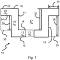
- FIG. 1 is a cross-section representation of certain components of a refractory element 10 of the present invention, showing their geometric relationship
- Refractory element 10 contains a base 12, which is depicted as being cylindrical in shape, and having a main orifice 13 which passes through the base from a base upper surface 14 to a base lower surface 15.
- a wall 16 extends upwardly from base upper surface 14.
- Wall 16 is disposed around the periphery of base 12.
- the wall has a wall interior surface 17, a wall upper surface 18 and a wall exterior surface 19.
- a wall circumferential lip 20 extends outwardly from wall 16.
- the wall circumferential lip 20 has a wall circumferential lip upper surface 22, a wall circumferential lip lower surface 24, and a wall circumferential lip exterior surface 25.
- Shielded volume 26 is the volume located below the wall circumferential lower surface 24.
- Operating shielded height 28 is the distance between base upper surface 14 and wall circumferential lip lower surface 24.
- Operating shielded volume 30 is the volume located below the wall circumferential lip lower surface 24 between the plane of base upper surface 14 and the plane of wall circumferential lip lower surface 24.
- Internal height 32 is the distance between base upper surface 14 and wall upper surface 18.
- Wall circumferential lip protrusion distance 34 is the distance between wall exterior surface 19 and the farthest radial extent of wall circumferential lip 20.
- Shielded height 36 is the distance between the plane of base lower surface 15 and the plane of wall circumferential iip lower surface 24.
- An interior volume 37 is partly defined by wall interior surface 17 and base upper surface 14.
- Fig. 2 depicts a refractory element 10 having an outwardly-extending wall circumferential lip located between the top and bottom of a circumferential wall.
- the element has a base 12 through which main orifice 13 passes vertically.
- Wall 16 extends upwardly from base upper surface 14 of base 12.
- the wall has a wall upper surface 18.
- Wall circumferential lip 20 extends radially outward from wall 16.
- the wall circumferential lip 20 has a wall circumferential lip upper surface 22.
- wall upper surface 18 and wall circumferential lip upper surface 22 occupy different horizontal planes.
- the plane of the wall circumferential lip lower surface 24 is located above the plane of the base upper surface 14 and above the plane of the base lower surface 15.
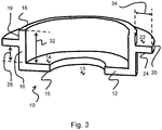
- Fig. 3 depicts a refractory element 10 having an outwardly-extending wall circumferential lip 20 located between the top and bottom of a circumferential wall.
- the element has a base 12 through which main orifice 13 passes vertically.
- Wall 16 extends upwardly from base upper surface 14 of base 12.
- the wall has a wall upper surface 18.
- Wall circumferential lip 20 extends radially outward from wall 16.
- the wall circumferential lip 20 has a wall circumferential lip upper surface 22 and a wall circumferential lip lower surface 24.
- wall upper surface 18 and wall circumferential lip upper surface 22 occupy different horizontal planes.
- the plane of the wall circumferential lip lower surface 24 is located above the plane of the base upper surface 14 and above the plane of the base lower surface 15.
- Height “H” is the distance between base upper surface 14 and wall upper surface 18, and is equivalent to internal height 32.
- Height “h” is the distance between the plane of base upper surface 14 and the plane of wall circumferential lip lower surface 24, and is equivalent to operating shielded height 28.
- the radial outward extent of wall circumferential lip 22 from wall exterior surface 19, indicated as "p" is equivalent to lip horizontal protrusion distance 34.
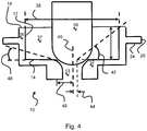
- Fig. 4 depicts a refractory element 10 having an outwardly-extending wall circumferential lip 20 located between the top and bottom of a circumferential wall.
- the element has a base 12 through which main orifice 13 passes vertically.
- Wall 16 extends upwardly from the base upper surface of base 12.
- the wall has a wall interior surface 17 and a wall upper surface 18.
- Wall circumferential lip 20 extends radially outward from wall 16.
- the wall circumferential lip 20 has a wall circumferential lip lower surface 24.
- interior maximum horizontal dimension 38 represents the maximum straight-line distance in a horizontal plane between one portion of wall interior surface 17 and another portion of wall interior surface 17, and is also designated as "2 ⁇ L" or "2L".
- Main orifice central axis 40 passes longitudinally, or vertically, through the main orifice 13.
- Element wall interior elevation angle 42 is described as the angle formed at the vertex of the intersection of a first line between (a) the intersection of wall interior surface 17 and wall upper surface 18 and (b) a point in the plane of base upper surface 14 displaced by a distance 44 (designated as "WDD") towards (a) from main orifice central axis 40, and a second line formed by the vertical projection of the first line on the plane of base upper surface 14.
- WDD 44 may have a value of 15 mm.
- WDD may also represent the minimum radius of main orifice 13.
- Lip lower surface elevation angle 46 is described as the angle formed at the vertex of the intersection of a first line extending between (a) the intersection of the wall circumferential lip external surface 25 and wall circumferential lip lower surface 24, and (b) a point in the plane of base upper surface 14 displaced by a distance 48 (designated as "LDD") towards (a) from main orifice central axis 40, and a second line formed by the vertical projection of the first line on the plane of upper base surface 14.
- LDD may have a value of 50mm, or may have the value of the radius of main orifice 13 at its intersection with base upper surface 14, or may have the value of the minimum radius of main orifice 13.
- element wall interior elevation angle 42 may have nonzero values less than 60 degrees, in the range from 60 degrees to 5 degrees, from 60 degrees to 10 degrees, from 60 degrees to 20 degrees, from 50 degrees to 5 degrees, from 50 degrees to 10 degrees, or from 50 degrees to 20 degrees.
- lip lower surface elevation angle 46 may have values in the range from 10 degrees to 80 degrees, 15 degrees to 80 degrees, 10 degrees to 60 degrees, 10 degrees to 50 degrees, or 10 degrees to 45 degrees.
- internal height 32 may be related to L (half the length of interior horizontal maximum dimension 38) by the relationship H ⁇ tan 10 ° + LDD ⁇ L ⁇ H ⁇ tan 70 ° + WDD
- 2 ⁇ L is the largest internal horizontal dimension of the inventive device.
- 2 ⁇ L represents the diameter, but the device may also have a square, rectangular, octagonal, triangular or other polygonal interior, or an oval interior.
- Stopper volume 50 represents a volume of the interior of the device that may be occupied by a stopper in use.
- the stopper rod takes the form of a cylindrical solid with a hemispherical solid joined to the cylindrical solid by contact of respective circular surfaces.
- Figure 5 depicts an embodiment of refractory element or block 10 in which a pair of internal fins 52 extend inwardly into the interior volume from wall interior surface 17. Internal fins 52 cooperate with a stopper occupying stopper volume 50 to reduce the formation of vortices in the interior volume of block 10.
- Wall circumferential lip 20 is displaced below the plane of the wall upper surface 18, is displaced above the plane of the base lower surface, and is displaced above the plane of the base upper surface.
- a block of the present invention may contain 1, 2, 3, 4, 5, 6, 7, 8, 9, 10, 11, or 12 internal fins.
- Figure 6 depicts an embodiment of refractory element or block 10 in which four internal fins 52 extend inwardly into the interior volume from wall interior surface 17. Internal fins 52 cooperate with a stopper occupying stopper volume 50 to reduce the formation of vortices in the interior volume of block 10.
- Wall circumferential lip 20 is disposed so that the plane of wall circumferential lip upper surface 22 is below the plane of the wall upper surface 18, and the plane of the wall circumferential lip lower surface is above the plane of the base lower surface, and above the plane of the base upper surface. In this embodiment, all molten metal must flow above wall circumferential lip upper surface 22 and above wall upper surface 18 to exit through the main orifice.
- Wall upper surface 18 is the uppermost portion or level of block 10.
- Figure 7 depicts an embodiment of refractory element or block 10 in which two internal fins 52 extend inwardly into the interior volume.
- the depicted embodiment contains three internal steps 54 formed in the face of the wall interior surface.
- the steps may be formed from right angles, obtuse angles, or may take the form of discrete bumps. In certain embodiments, a plurality of steps is required.
- the wall circumferential lip upper surface 22 of wall circumferential lip 20 occupies the same plane as does the wall upper surface 18.
- Figure 8 depicts an embodiment of refractory element or block 10 in which four internal fins 52 extend inwardly into the interior volume.
- the depicted embodiment contains four levels of internal steps 54 formed in the face of the wall interior surface. Fins 52 and steps 54 cooperate with a stopper occupying stopper volume 50 to minimize the formation of vortices and to produce turbulence in the flow through the main orifice to minimize deposition.
- the upper surface 22 of wall circumferential lip 20 is displaced downwardly from the plane of wall upper surface 18 of wall 16.
- the lower surface of the wall circumferential lip is displaced upwards from the base lower surface.
- all molten metal must flow above wall circumferential lip upper surface 22 and above wall upper surface 18 to exit through the main orifice.
- Wall upper surface 18 is the uppermost portion or level of block 10.
- a block of the present invention may contain 1, 2, 3, 4, 5, 6, 7, 8, 9, 10, 11, 12, 13, 14, 15, or 16 levels of internal steps 54.
- Figure 9 depicts an embodiment of refractory element or block 10 in which six internal fins 52 extend inwardly into the interior volume.
- the depicted embodiment contains four levels of internal steps 54 formed in the face of the wall interior surface. Fins 52 and steps 54 cooperate with a stopper occupying stopper volume 50 to minimize the formation of vortices and to produce turbulence in the flow through the main orifice to minimize deposition.
- the upper surface 22 of wall circumferential lip 20 is displaced downwardly from the plane of wall upper surface 18 of wall 16.
- the lower surface of the wall circumferential lip is displaced upwards from the base lower surface. In this embodiment, all molten metal must flow above wall circumferential lip upper surface 22 and above wall upper surface 18 to exit through the main orifice.
- Wall upper surface 18 is the uppermost portion or level of block 10.
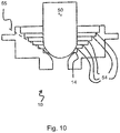
- Figure 10 depicts an embodiment of refractory element or block 10 containing a plurality of levels of internal steps 54 formed in the face of the wall interior surface.
- Tangent line 55 is a line tangent to the surfaces of the nose of a stopper occupying stopper volume 50 and the seat of this stopper in the interior volume of block 10.
- the tangent line intersects an internal step 54, a plurality of internal steps 54, or at least three internal steps 54. All of internal steps 54 are located at a level above the level of base upper surface 14.
- Base upper surface 14 is at the same level as the entrance of the tundish to mold casting channel where block 10 is used in a tundish.
- the tundish to mold casting channel starts at the level of surface 14 or below.
- a step or a plurality of steps 54 is present in a block of the present invention; this configuration is distinguished from the use of a single step in the seat of a tundish to mold casting channel.
- Figure 11 depicts an embodiment of refractory element or block 10 containing a plurality of levels of internal steps 54 formed in the face of the wall interior surface. Fins 52 and steps 54 cooperate with a stopper occupying stopper volume 50 to minimize the formation of vortices and to produce turbulence in the flow through main orifice 13 to minimize deposition.
- Wall circumferential lip 20 is displaced below the plane of the wall upper surface 18, and is displaced from the plane of base lower surface 15.
- Figure 12 depicts an embodiment of refractory element or block 10 containing a plurality of levels of internal steps 54 formed in the face of the wall interior surface. Fins 52 and steps 54 cooperate with a stopper occupying stopper volume 50 to minimize the formation of vortices and to produce turbulence in the flow through main orifice 13 to minimize deposition.
- a wall circumferential lip 20 extends horizontally and outwardly from the exterior of the wall of block 10.
- Entrance flow openings 56 have, at their entrances, a lower surface equivalent to wall circumferential lip upper surface 22. Entrance flow openings 56 are defined, in the horizontal plane, by surfaces of adjacent internal fins 52. Entrance flow openings 56 are in fluid communication with the interior of the device or block, and direct flow onto internal steps 54. Entrance flow openings 56 are flared inwardly in the horizontal plane.
- entrance flow openings 56 have a wall having an initial vertical surface 57 contained in a plane that does not intersect stopper volume 50. This geometry maximizes flow rotation around the stopper.
- Figure 13 depicts an embodiment of refractory element or block 10 containing a plurality of levels of internal steps 54 formed in the face of the wall interior surface. Fins 52 and steps 54 cooperate with a stopper occupying stopper volume 50 to minimize the formation of vortices and to produce turbulence in the flow through the main orifice to minimize deposition.
- a wall circumferential lip 20 extends horizontally and outwardly from the exterior of the wall of block 10.
- Entrance flow openings 56 have, at their entrances, a lower surface equivalent to wall circumferential lip upper surface 22. Entrance flow openings 56 are defined, in the horizontal plane, by surfaces of adjacent internal fins 52. Entrance flow openings 56 are in fluid communication with the interior volume 37 of the device or block, and direct flow onto internal steps 54.
- Entrance flow openings 56 are flared inwardly in the horizontal plane.
- entrance flow openings 56 have a wall having an initial vertical surface 57 contained in a plane that does not intersect stopper volume 50. This geometry maximizes flow rotation around the stopper.
- entrance flow openings 56 have an outer wall 58 having an entrance flow opening outer wall concave section 59.
- the angle formed by the entrance flow opening outer wall concave section 59 is in the range from 90 degrees to 160 degrees, from 190 degrees to 150 degrees, from 90 degrees to 140 degrees, from 90 degrees to 130 degrees, from 90 degrees to 120 degrees, from 90 degrees to 110 degrees, from 100 degrees to 160 degrees, from 100 degrees to 150 degrees, from 100 degrees to 140 degrees, from 100 degrees to 130 degrees, from 100 degrees to 120 degrees, or from 100 degrees to 110 degrees.
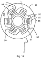
- Figure 14 is a top view of an embodiment of refractory element or block 10 containing a plurality of levels of internal steps 54 formed in the face of the wall interior surface. Fins 52 and steps 54 cooperate with a stopper occupying stopper volume 50 to minimize the formation of vortices and to produce turbulence in the flow through the main orifice to minimize deposition.
- a wall circumferential lip 20 extends horizontally and outwardly from the exterior of the wall of block 10. Entrance flow openings 56 have, at their entrances, a lower surface equivalent to wall circumferential lip upper surface 22. Entrance flow openings 56 are defined, in the horizontal plane, by surfaces of adjacent internal fins 52.
- Entrance flow openings 56 are in fluid communication with the interior volume of the device or block, and direct flow onto internal steps 54. Entrance flow openings 56 are flared inwardly in the horizontal plane.
- entrance flow openings 56 have a wall having an initial vertical surface 57 contained in a plane that does not intersect stopper volume 50.
- the plane containing wall initial vertical surface 57 is indicated by a dotted line that does not intersect stopper occupying volume 50. This geometry maximizes flow rotation around the stopper.
- entrance flow openings 56 have an outer wall 58 having an entrance flow opening outer wall concave section 59. Entrance flow opening outer wall concave section 59 redirects inwardly the outer portion of flow through entrance flow opening 56.
- the major axis, in the horizontal plane, of entrance flow openings 56 is not collinear with any horizontal radius of the stopper volume. This configuration induces flow rotation within the interior volume of block 10.
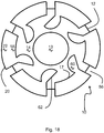
- Figure 15 is a top view of an embodiment of block 10 of the invention.
- walls extend upwardly from base upper surface 14, and wall upper surface 18 is visible in this view.
- a wall circumferential lip projects outwardly from the wall; wall circumferential lip upper surface 22 is visible in this view.
- the wall and the wall circumferential lip are interrupted circumferentially by entrance flow openings 56.
- the major axis, in the horizontal plane, of each entrance flow opening 56 is collinear with a horizontal radius of the stopper volume 50.
- the major axis in the horizontal plane of each entrance flow opening 56 intersects a deflector 60 extending upwardly from base upper surface 14.
- Each deflector 60 comprises, in a direction facing a corresponding entrance flow opening 56, an angled facet 62 having an angle other than a right angle with the major axis, in the horizontal plane, of the corresponding entrance flow opening.
- the angle other than a right angle may be in the range from 91° to 179°, 95° to 175°, 100° to 170°, 100° to 160°, 100° to 150°, 100° to 140°, 115° to 155°, or 120° to 150°.
- the deflector may also have any other geometry that redirects a flow through an entrance flow opening in a direction circumferential to the horizontal radius of stopper volume 50.
- Figure 16 is a perspective representation of the embodiment of block 10 illustrated in Figure 15 .
- walls 16 extend upwardly from base upper surface 14 of base 12; wall inner surface 17, wall upper surface 18 and wall outer surface 19 are visible in this view.
- Main orifice 13 passes vertically through base 12 between base upper surface 14 and the base lower surface.
- a wall circumferential lip 20 projects outwardly from wall 16; wall circumferential lip upper surface 22 is visible in this view.
- the wall and the wall circumferential lip are interrupted circumferentially by entrance flow openings 56.
- the major axis, in the horizontal plane, of each entrance flow opening 56 is collinear with a horizontal radius of the longitudinal axis of block 10.
- each entrance flow opening 56 intersects a deflector 60 extending upwardly from base upper surface 14.
- Each deflector 60 comprises, in a direction facing a corresponding entrance flow opening 56, an angled facet 62 having an angle other than a right angle with the major axis, in the horizontal plane, of the corresponding entrance flow opening.
- FIG 17 is an additional perspective representation of the embodiment of block 10 illustrated in Figure 15 .
- walls 16 extend upwardly from base upper surface 14 of base 12; wall inner surface 17, wall upper surface 18 and wall outer surface 19 are visible in this view.
- a wall circumferential lip 20 projects outwardly from wall 16; wall circumferential lip upper surface 22 is visible in this view.
- Wall upper surface 18 and wall circumferential lip upper surface 22 are co-planar.
- the wall and the wall circumferential lip are interrupted circumferentially by entrance flow openings 56.
- the major axis, in the horizontal plane, of each entrance flow opening 56 is collinear with a horizontal radius of the vertical longitudinal axis of block 10.
- each entrance flow opening 56 intersects a deflector 60 extending upwardly from base upper surface 14.
- Each deflector 60 comprises, in a direction facing a corresponding entrance flow opening 56, an angled facet 62 having an angle other than a right angle with the major axis, in the horizontal plane, of the corresponding entrance flow opening.
- the floors of entrance flow openings 56 are flat, and form right angles with the walls of the respective entrance flow openings 56.
- Figure 18 is a top view of an embodiment of block 10 of the invention.
- walls extend upwardly from base upper surface 14, and wall upper surface 18 is visible in this view.
- Main orifice 13 passes vertically through base 12 between base upper surface 14 and the base lower surface.
- a wall circumferential lip 20 projects outwardly from the wall; wall circumferential lip upper surface 22 is visible in this view.
- the wall and the wall circumferential lip are interrupted circumferentially by entrance flow openings 56.
- the major axis, in the horizontal plane, of each entrance flow opening 56 is collinear with a horizontal radius of extending from the central vertical axis of block 10.
- the major axis in the horizontal plane of each entrance flow opening 56 intersects a deflector 60 extending upwardly from base upper surface 14.
- Each deflector 60 comprises, in a direction facing a corresponding entrance flow opening 56, an angled facet 62 having an angle other than a right angle with the major axis, in the horizontal plane, of the corresponding entrance flow opening.
- each deflector 60 is in direct communication with a portion of wall interior surface 17.
- each deflector 60 intersects a portion of wall interior surface along one line segment that is the vertex of an angle that is acute in the horizontal plane and at along another line segment that is the vertex of an angle that is obtuse in the horizontal plane.
- the obtuse angle is formed by the intersection of a wall of entrance flow opening 56 with angled facet 62.
- Figure 19 is a perspective representation of the embodiment of block 10 of the invention shown in Figure 18 .
- wall 16 extends upwardly from base upper surface 14, and wall interior surface 17, wall upper surface 18 and wall exterior surface 19 are visible in this view.
- a wall circumferential lip 20 projects outwardly from the wall; wall circumferential lip upper surface 22 is visible in this view.
- the wall and the wall circumferential lip are interrupted circumferentially by entrance flow openings 56.
- the major axis, in the horizontal plane, of each entrance flow opening 56 is collinear with a horizontal radius of extending from the central vertical axis of block 10.
- the major axis in the horizontal plane of each entrance flow opening 56 intersects a deflector 60 extending upwardly from base upper surface 14.
- Each deflector 60 comprises, in a direction facing a corresponding entrance flow opening 56, an angled facet 62 having an angle other than a right angle with the major axis, in the horizontal plane, of the corresponding entrance flow opening.
- each deflector 60 is in direct communication with a portion of wall interior surface 17.
- each deflector 60 intersects a portion of wall interior surface along one line segment that is the vertex of an angle that is acute in the horizontal plane and at along another line segment that is the vertex of an angle that is obtuse in the horizontal plane.
- the obtuse angle is formed by the intersection of a wall of entrance flow opening 56 with angled facet 62.
- Figure 20 is a top view of an embodiment of block 10 of the invention.
- walls extend upwardly from base upper surface 14, and wall upper surface 18 is visible in this view.
- Main orifice 13 passes vertically through the base between base upper surface 14 and the base lower surface.
- a wall circumferential lip 20 projects outwardly from the wall; wall circumferential lip upper surface 22 is visible in this view.
- the wall and the wall circumferential lip are interrupted circumferentially by entrance flow openings 56.
- the major axis, in the horizontal plane, of each entrance flow opening 56 is collinear with a horizontal radius of extending from the central vertical axis of block 10.
- the major axis in the horizontal plane of each entrance flow opening 56 intersects a deflector 60 extending upwardly from base upper surface 14.
- Each deflector 60 comprises, in a direction facing a corresponding entrance flow opening 56, an angled facet 62 having an angle other than a right angle with the major axis, in the horizontal plane, of the corresponding entrance flow opening.
- each deflector 60 is in direct communication with a portion of wall interior surface 17.
- each deflector 60 intersects a portion of wall interior surface along a vertical line segment that is the vertex of an angle that is obtuse in the horizontal plane. The obtuse angle is formed by the intersection of a wall of entrance flow opening 56 with angled facet 62.
- each deflector 60 also has an intersection with a portion of wall interior surface that is described by a concave curve in the horizontal plane.
- Entrance flow opening outlet 65 is the junction of the floor of the entrance flow opening with the base upper surface, and may take the form of a step.
- Figure 21 is a perspective view of the embodiment of block 10 of the invention shown in Figure 20 .
- wall 16 extends upwardly from base upper surface 14 of base 12, and wall interior surface 17, wall upper surface 18 and wall exterior surface 19 are visible in this view.
- Main orifice 13 passes vertically through the base between base upper surface 14 and the base lower surface.
- a wall circumferential lip 20 projects outwardly from the wall; wall circumferential lip upper surface 22 is visible in this view.
- the wall and the wall circumferential lip are interrupted circumferentially by entrance flow openings 56.
- the major axis, in the horizontal plane, of each entrance flow opening 56 is collinear with a horizontal radius of extending from the central vertical axis of block 10.
- each deflector 60 comprises, in a direction facing a corresponding entrance flow opening 56, an angled facet 62 having an angle other than a right angle with the major axis, in the horizontal plane, of the corresponding entrance flow opening.
- each deflector 60 is in direct communication with a portion of wall interior surface 17.
- each deflector 60 intersects a portion of wall interior surface along a vertical line segment that is the vertex of an angle that is obtuse in the horizontal plane. The obtuse angle is formed by the intersection of a wall of entrance flow opening 56 with angled facet 62.
- each deflector 60 also has an intersection with a portion of wall interior surface that is described by a concave curve in the horizontal plane. This curved surface redirects flow near wall interior surface 17 towards the interior volume of block 10.
- the floors of entrance flow openings 56 are horizontal and meet the walls of entrance flow openings 56 at rounded corners or radii 64. In other embodiments, the floors of entrance flow openings 56 are horizontal and meet the walls of entrance flow openings 56 through bevels.
- Figure 22 is a top view of an embodiment of block 10 of the invention.
- walls extend upwardly from base upper surface 14, and wall upper surface 18 is visible in this view.
- Main orifice 13 passes vertically through the base between base upper surface 14 and the base lower surface.
- a wall circumferential lip 20 projects outwardly from the wall; wall circumferential lip upper surface 22 is visible in this view.
- wall upper surface 18 and wall circumferential lip upper surface 22 are not co-planar; wall circumferential lip upper surface 22 is below the level of wall upper surface 18.
- a top portion of the wall above wall circumferential lip upper surface 22 is interrupted circumferentially by entrance flow openings 56.
- each entrance flow opening 56 is collinear with a horizontal radius of extending from the central vertical axis of block 10.
- the major axis in the horizontal plane of each entrance flow opening 56 intersects a deflector 60 extending upwardly from base upper surface 14.
- Each deflector 60 comprises, in a direction facing a corresponding entrance flow opening 56, an angled facet 62 having an angle other than a right angle with the major axis, in the horizontal plane, of the corresponding entrance flow opening.
- each deflector 60 is in direct communication with a portion of wall interior surface 17.
- each deflector 60 intersects a portion of wall interior surface along a vertical line segment that is the vertex of an angle that is obtuse in the horizontal plane.
- the obtuse angle is formed by the intersection of a wall of entrance flow opening 56 with angled facet 62.
- each deflector 60 also has an intersection with a portion of wall interior surface that is described by a concave curve in the horizontal plane. This curved surface redirects flow near wall interior surface 17 towards the interior volume of block 10.
- the floors of entrance flow openings 56 are horizontal and meet the walls of entrance flow openings 56 at rounded corners or radii 64. In other embodiments, the floors of entrance flow openings 56 are horizontal and meet the walls of entrance flow openings 56 through bevels.
- Entrance flow opening outlet 65 is located at the junction of the floor of the entrance flow opening with an intermediate entrance flow opening floor level 67, and may take the form of a step.
- the intersections of intermediate entrance opening floor level 67 with angled facet 62 and wall interior surface 17 are in the form of rounded corners or radii 64.
- Intermediate volume outlet 68 is located at the junction of the floor of intermediate entrance flow opening floor level 67 and base upper surface 14, may be in the form of a step.
- Figure 23 is a perspective view of the embodiment of block 10 of the invention illustrated in Figure 22 .
- walls extend upwardly from base upper surface 14, and wall interior surface 17, wall upper surface 18 and wall exterior surface 19 are visible in this view.
- Main orifice 13 passes vertically through the base between base upper surface 14 and the base lower surface.
- a wall circumferential lip 20 projects outwardly from the wall; wall circumferential lip upper surface 22 is visible in this view.
- wall upper surface 18 and wall circumferential lip upper surface 22 are not co-planar; wall circumferential lip upper surface 22 is below the level of wall upper surface 18.
- a top portion of wall above wall circumferential lip upper surface 22 is interrupted circumferentially by entrance flow openings 56.
- each entrance flow opening 56 is collinear with a horizontal radius of extending from the central vertical axis of block 10.
- the major axis in the horizontal plane of each entrance flow opening 56 intersects a deflector 60 extending upwardly from base upper surface 14.
- Each deflector 60 comprises, in a direction facing a corresponding entrance flow opening 56, an angled facet 62 having an angle other than a right angle with the major axis, in the horizontal plane, of the corresponding entrance flow opening.
- each deflector 60 is in direct communication with a portion of wall interior surface 17.
- each deflector 60 intersects a portion of wall interior surface along a vertical line segment that is the vertex of an angle that is obtuse in the horizontal plane.
- the obtuse angle is formed by the intersection of a wall of entrance flow opening 56 with angled facet 62.
- each deflector 60 also has an intersection with a portion of wall interior surface that is described by a concave curve in the horizontal plane. This curved surface redirects flow near wall interior surface 17 towards the interior volume of block 10.
- the floors of entrance flow openings 56 are horizontal and meet the walls of entrance flow openings 56 at rounded corners or radii 64. In other embodiments, the floors of entrance flow openings 56 are horizontal and meet the walls of entrance flow openings 56 through bevels.
- Entrance flow opening outlet 65 is located at the junction of the floor of the entrance flow opening with an intermediate entrance flow opening floor level that may be depressed with respect to the floor of the entrance flow opening, and may take the form of a step.
- Figure 24 is an additional perspective view of the embodiment of block 10 of the invention depicted in Figure 22 .
- wall 16 extends upwardly from base upper surface 14, and wall interior surface 17, wall upper surface 18 and wall exterior surface 19 are visible in this view.
- Main orifice 13 passes vertically through the base between base upper surface 14 and the base lower surface.
- a wall circumferential lip 20 projects outwardly from wall 16; wall circumferential lip upper surface 22 is visible in this view.
- wall upper surface 18 and wall circumferential lip upper surface 22 are not co-planar; wall circumferential lip upper surface 22 is below the level of wall upper surface 18.
- a top portion of wall 16 above wall circumferential lip upper surface 22 is interrupted circumferentially by entrance flow openings 56.
- each entrance flow opening 56 is collinear with a horizontal radius of extending from the central vertical axis of block 10.
- the major axis in the horizontal plane of each entrance flow opening 56 intersects a deflector 60 extending upwardly from base upper surface 14.
- Each deflector 60 comprises, in a direction facing a corresponding entrance flow opening 56, an angled facet 62 having an angle other than a right angle with the major axis, in the horizontal plane, of the corresponding entrance flow opening.
- each deflector 60 is in direct communication with a portion of wall interior surface 17.
- each deflector 60 intersects a portion of wall interior surface along a vertical line segment that is the vertex of an angle that is obtuse in the horizontal plane.
- the obtuse angle is formed by the intersection of a wall of entrance flow opening 56 with angled facet 62.
- each deflector 60 also has an intersection with a portion of wall interior surface that is described by a concave curve in the horizontal plane. This curved surface redirects flow near wall interior surface 17 towards the interior volume of block 10.
- the floors of entrance flow openings 56 are horizontal, are co-planar with wall circumferential lip upper surface 22, and meet the walls of entrance flow openings 56 at rounded corners or radii 64.
- Entrance flow opening outlet 65 is located at the junction of the floor of the entrance flow opening with an intermediate entrance flow opening floor level 67, and takes the form of a step.
- the intersections of intermediate entrance opening floor level 67 with angled facet 62 and wall interior surface 17 are in the form of rounded corners or radii 64.
- Intermediate volume outlet 68 is located at the junction of the floor of intermediate entrance flow opening floor level 67 and base upper surface 14, and takes the form of a step.
- Entrance flow opening 56 is in fluid communication with the volume above intermediate entrance floor level 67 by way of entrance flow opening outlet 65; the volume above intermediate entrance floor level 67 is fluid communication with the volume above base upper surface 14 by way of intermediate entrance flow opening outlet 68.
- Figure 25 is a top view of an embodiment of block 10 of the invention.
- walls extending upwardly from base upper surface 14 take the form of a plurality of cylinders or columnar wall components 70 disposed around the circumference of base upper surface 14.
- the upper surfaces of columnar wall components 70 represent wall upper surface 18.
- Main orifice 13 passes vertically through the base between base upper surface 14 and the base lower surface. Entrance flow openings 56 are formed by the spaces between adjacent columnar wall components 70.
- This embodiment makes use of a plurality of columnar wall components 70. For example, 2, 3, 4, 5, 6, 7, 8, 9, 10, 11, 12, 13, 14, 15, 16, 17, 18, 19, 20, 21, 22, 23 or 24 columnar wall components may be used.
- Deflectors 60 extend upwardly from base upper surface 14 in the interior volume block 10 between the columnar wall components 70 and the central vertical axis of block 10. A line passing, in the horizontal plane, through the midpoint of an entrance flow opening 56 intersects a corresponding deflector 60.
- Each deflector 60 comprises, in a direction facing a corresponding entrance flow opening 56, an angled facet 62 having an angle other than a right angle with the major axis, in the horizontal plane, of the corresponding entrance flow opening.
- deflectors 60 take the form of cylinders or columns with a plurality of angled facets on the radial surfaces.
- Figure 26 is a perspective view of the embodiment of block 10 depicted in Figure 25 .
- walls extending upwardly from base upper surface 14 take the form of a plurality of cylinders or columnar wall components 70 disposed around the circumference of base upper surface 14.
- the upper surfaces of columnar wall components 70 represent wall upper surface 18.
- Main orifice 13 passes vertically through the base between base upper surface 14 and the base lower surface. Entrance flow openings 56 are formed by the spaces between adjacent columnar wall components 70.
- This embodiment makes use of a plurality of columnar wall components 70.
- Deflectors 60 extend upwardly from base upper surface 14 in the interior volume block 10 between the columnar wall components 70 and the central vertical axis of block 10.
- Each deflector 60 comprises, in a direction facing a corresponding entrance flow opening 56, an angled facet 62 having an angle other than a right angle with the major axis, in the horizontal plane, of the corresponding entrance flow opening.
- deflectors 60 take the form of cylinders or columns with a plurality of angled facets on the radial surfaces.
Landscapes
- Engineering & Computer Science (AREA)
- Mechanical Engineering (AREA)
- Furnace Housings, Linings, Walls, And Ceilings (AREA)
- Continuous Casting (AREA)
- Furnace Charging Or Discharging (AREA)
- Casting Support Devices, Ladles, And Melt Control Thereby (AREA)
Description
- The present invention relates to the continuous casting of steel and particularly to the problems of high residence time steel exiting the outlet of a refractory vessel and increased likelihood of clogging, and the deposition of nonmetallic inclusions at the outlet of a refractory vessel. The invention is configured to prevent vortex tubes from reaching the outlet and carrying slag to the outlet, and introduces controlled turbulence in the outlet to delay the deposition of nonmetallic inclusions. The invention is also configured to combine cold steel at the bottom of a refractory vessel, in a controlled matter, with steel in the body of the vessel to homogenize the temperature of steel exiting from the vessel and to avoid clogging produced by the passage of an excessive proportion of cold steel. In particular, the invention relates to a refractory piece that modifies the liquid steel flow inside a refractory vessel as the flow is directed towards the outlet. The refractory piece may achieve these effects in conjunction with a stopper. The invention also relates to an assembly comprising a refractory piece as described previously, in conjunction with a stopper. The stopper may have a rippled exterior; the ripples may form concentric rings on the end of the stopper in proximity to the outlet of the refractory vessel.
- With growing demands for quality and property control, cleanliness of steel becomes more and more important. Issues like controlling the chemical composition and the homogeneity remain important, but have been joined by concerns generated by the presence of non-metallic inclusions and by clogging.
- The presence of aluminum oxide and spinel inclusions is considered as harmful both for the production process itself as for the steel properties. These inclusions are mainly formed during the deoxidation of the steel in the ladle, which is necessary for continuous casting. Incomplete removal of the non-metallic inclusions during secondary metallurgy and reoxidation of the steel melt cause nozzle clogging during continuous casting. The layer of clogged material contains generally large clusters of aluminum oxide. Its thickness is related to the amount of steel cast as well as to the cleanliness of the steel. Nozzle clogging results in a decreased productivity, because less steel can be cast per unit of time (as result of the decreasing diameter) and due to replacement of nozzles with concurrent casting interruptions. Besides clogging, the presence of reoxidation products may give rise to erosion of the nozzle and to the formation of inclusion defects in the steel.
-
US2014061257 describes a refractory element configured to prevent or limit steel re-oxidation in a steel casting process. The refractory element contains a base surrounded by a peripheral wall comprising a smooth internal wall. The refractory element is positioned upstream of and surrounding a nozzle forming a casting channel of a tundish. The refractory element prevents or limits steel re-oxidation and prevents oxidation products from entering the casting channel. -
WO2005042189 describes a stopper rod system for use in a metallurgical vessel, comprising a stopper rod and a nozzle. At least one of the stopper rod nose and the internal surface of the nozzle bore comprise a plurality of ripples or steps that are arranged such that the size of a flow channel between the stopper rod nose and the internal stopper rod when the stopper rod system is in an open position discontinuously increases in size as a function of the distance downstream of the point of contact between the stopper rod and the nozzle. The stopper rod system addresses the problem of clogging or restriction of a liquid metal flow by the deposition and aggregation of non-metallic materials on the stopper nose and/or on the nozzle bore surface. - Clogging can also be produced by the entrainment of materials at or near the surface of the molten metal (e.g., slag) in the molten metal itself. Transferring molten metal from a metallurgical vessel also involves the separation of an impurity containing slag (the supernatant light phase) from a refined or partly refined metal (steel) below. As the flow from the vessel takes place, it is not uncommon for a funnel or vortex to be created which can entrain large amounts of slag into the flow of the liquid metal with resulting metal quality problems downstream.
- Flow behavior in an emptying vessel is influenced by the rotational velocity components in the liquid. In the absence of such velocity components, liquid leaving the emptying vessel is drawn mainly from a hemi-spheroidal region surrounding the exit nozzle, and surface liquid far above the drainage nozzle shows little motion. Toward the very end of the drainage, entrainment of the supernatant fluid does occur as a non-vortexing funnel through a funnel-shaped core.
- it would therefore be desirable to provide a solution which would produce the homogenization of the temperature of molten steel passing through the outlet of a refractory vessel, and the reduction or delay of the deposition of nonmetallic inclusions in or below the outlet, while avoiding vortexing and entrainment of supernatant fluid in the exit flow form the refractory vessel.
- The objects of the present invention are the homogenization of the temperature of molten steel passing through the outlet of a refractory vessel, and the reduction or delay of the deposition of nonmetallic inclusions in or below the outlet.
- These objects are achieved by a refractory piece or block according to claim 1 that modifies, within a refractory vessel, the liquid steel flow directed towards the outlet. It may, alone or in conjunction with other refractory pieces, prevent vortex tubes from reaching the outlet. It may control the mixing of cold or high residence time steel with higher-temperature steel with a lower residence time, in the vicinity of the outlet. It may introduce turbulence downstream of the refractory vessel outlet to delay the deposition of nonmetallic inclusions, for example, at the entrance of a casting channel located at the refractory vessel outlet.
- Specifically, these objects are achieved by the use of a block or surrounding refractory element, an assembly of a nozzle and a block or surrounding refractory element, or an assembly of a nozzle and a block or surrounding refractory element housed in a refractory vessel such as a tundish, in which the block or surrounding refractory element has a base having an upper surface, a bottom and a wall extending upwardly from the main surface, the wall extending upwards typically at the periphery of the main surface. The wall may be continuous or may be comprised of a plurality of protrusions extending upwardly from the main surface. The block or surrounding refractory element comprises, in the base, an opening that may be disposed to be in fluid communication with the outlet of the refractory vessel. In this configuration, the base of the block or surrounding refractory element surrounds the outlet of the refractory vessel.
- This basic configuration of the block or surrounding refractory element may be modified by the inclusion of one or more, in any combination, design features to achieve the desired effects of the invention. Design features 1 and 3 below are included in the claims.
- A first design feature is a circumferential lip extending radially outwardly from the circumferential external surface of the wall of the block or surrounding refractory element. The contents of the volume beneath the circumferential lip are impeded from flowing directly through the outlet, and mix with the contents above the circumferential lip in a controlled manner.
- A second design feature is the presence of one or more fins on the interior surface of the block or surrounding refractory element. The fins extend inwardly. In certain configurations, the fins do not extend into the volume described by an upward projection of the outlet, or into a volume within a defined radial extension of an upward projection of the outlet.
- A third design feature is the introduction of a roughened surface onto the interior surface of the block or surrounding refractory element. The roughness takes the form of protrusions or steps. In certain configurations, the steps may be oriented so that their surfaces facing an upward projection of the outlet may be generated by rotation, around the primary axis of the outlet of a series of radii with lengths that incrementally decrease on proceeding towards the base lower surface.
- A fourth design feature is the presence of one or more entrance flow openings extending from the wall circumferential external surface to the wall circumferential internal surface.
- A fifth design feature is the presence of a plurality of barriers extending upwardly from the circumference of the base upper surface of the device to form the wall. Each barrier is circumferentially adjacent on each side to a circumferentially adjacent barrier.
- The invention may contain the first feature, the second feature, the third feature, the fourth feature, the fifth feature, features 1 and 2, features 1 and 3, features 1 and 4, features 1 and 5, features 2 and 3, features 2 and 4, features 2 and 5, features 3 and 4, features 3 and 5, features 1, 2 and 3, features 1, 2, and 4, features 1, 2 and 5, features 2, 3 and 4, features 2, 3 and 5, features 1, 2, 3 and 4, or features 1, 2, 3 and 5.
- Thanks to the particular arrangement according to the present invention, the cold molten steel at the bottom of a refractory vessel is mixed in a controlled ratio with hotter molten steel in the body of the refractory vessel. In addition, inclusions present in the metallurgical vessel flow past geometries in the block that induce turbulence as they exit; consequently they are entrained in the flow rather than precipitating from the molten metal stream and clogging the block outlet.
- It must be understood that the element surrounding the nozzle can be of any appropriate shape. In function of the metallurgical vessel design; it can be circular, oval or polygonal; its main orifice can be central or eccentric. In an alternate embodiment of the invention, appropriate shapes for the element may exclude circular shapes. The element surrounding the nozzle can also be cut off so as to accommodate those cases when one or more tundish walls are close to the pouring orifice. The main surface of the element can be planar or not (it can be frusto-conical, rippled, inclined). The nozzle can be an inner nozzle (for example in case the molten steel flow is controlled with a slide gate valve or if the installation is equipped with a tube or calibrated nozzle changer) or a submerged entry nozzle or SEN (for example in the case of stopper control). The metallurgical vessel or tundish can be equipped with one or more of such devices.
- As the element surrounding the nozzle need not be circular, and as the element may be placed in a vessel that does not have circular symmetry, it may be important to align the element with the nozzle, and therefore with the nozzle's surroundings, to produce desired flow patterns in the vicinity of the nozzle. Accordingly, the element and the nozzle may be constructed with matching visual indicators or markings that, when aligned or placed in contact, produce the desired geometrical arrangement of the element and the nozzle. Alternatively, the element and the nozzle may be constructed with mating geometries so that, when these geometries are mated, the desired geometrical arrangement of the element and nozzle, and of the combined element and nozzle with their surroundings, is produced. The mating geometries may be a matching recess and protrusion, a matching groove and lip, a matching peg and bore, a matching notch and protrusion, a matching dimple and mogul, a matching ridge and groove, aligned threaded receivers, aligned key or bayonet receivers, or matching non-circular surface geometries such as oval or polygonal faces. The mating geometry of the element may be placed within its main orifice or on the bottom of the base. The element, considered alone, may contain, within its main orifice or on its base, one or more orienting geometries, such as pegs, bores, protrusion, recesses, notches, bevels, dimples, moguls, ridges, grooves, housings for screw or bayonet fittings, or shaped or threaded receiver portions. The bore of the element may be asymmetric, oval or polygonal in shape.
- According to the present invention, the refractory element comprises a base having a main surface and a wall surrounding the main surface, the upper surface of the periphery being higher than the base surface of the refractory element. It must be understood that the upper surface of the wall does not need to be planar. It can be waved or have different heights along its circumference (for example higher in area of its circumference close to a vessel lateral wall and lower on the other side). The wall may contain one or more interruptions or openings. The wall may contain stepped changes in height, or may contain gradual changes in height. The upper face of the wall may have a sawtooth configuration, a semicircular notch configuration, a square notch configuration, a wave configuration, a semicircular protrusion configuration or may contain one or more steps. The upper face of the wall may be in communication with an outwardly protruding lip. The upper face of the wall may be in communication with an inwardly protruding lip. In certain embodiments of the invention, the upper face of the wall may be completely exposed, having no direct contact with any other element of the block. The wall may consist of a plurality of cylinders, or solids in the form of vertical projections of polygons, arranged with longitudinal axes extending from, and perpendicular, to the upper surface of the base. The wall may contain one or more ports; these ports may be circular, oval or polygonal in shape, and the ports may have horizontal axes, axes directed upwards and inwardly, axes directed downwards and inwardly, or axes that are not perpendicular to the external surface of the periphery. The ports may have bottoms that are rectangular, rectangular with rounded corners, or formed by obtuse angles. The ports may be configured to have axes that are mutually tangent to a circle within the periphery. The ports may be inwardly flared so that the cross-section of a port increases in the direction of the main orifice.
- In embodiments of the present invention having a wall circumferential lip, the distance from the upper surface of the base to the lower surface of the wall circumferential lip, designated "h", and the distance from the upper surface of the base to the upper surface of the wall, also expressed as the internal height of the device, designated "H", may be related as 2h < H < 3h, 2h < H < 4h, or 2h < H < 5h.
- In embodiments of the present invention having a wall circumferential lip, the distance from the upper surface of the base to the lower surface of the wall circumferential lip, designated "h", and the distance from the exterior surface of the wall to the furthest extent of the lip, designated "p", may be related as 0.1h < p < 2h, 0.2h < p < 2h, or 0.5h < p < 2h.
- In embodiments of the present invention having a wall circumferential lip, the distance from the upper surface of the base to the upper surface of the wall, also expressed as the internal height of the device, designated "H", may be related to the largest internal horizontal dimension, from interior surface of the wall to another portion of the interior surface of the wall, designated "2L", by the relationship H × tan(10°) + 50 mm < L < H × tan(70°) + 15 mm.
- The periphery of the refractory element of the present invention may take the form of a wall with measurements that are related to other measurements of the element by particular ratios or ranges of ratios. In certain embodiments, the maximum height of the wall, measured from the bottom of the base, has a ratio of 1:1 to 6:1, or 1.1:1 to 6:1, to the minimum height of the wall, measured from the bottom of the base. In certain embodiments, the maximum height of the wall, measured from the bottom of the base, has a ratio of 0.1:1 to 10:1, or 0.1:1 to 8.5:1, or 0.2:1 to 8.5:1, or 0.5:1 to 8.5:1, to the maximum exterior diameter of the base. In certain embodiments, the wall has a minimum thickness of 2 mm, 5 mm, or 10 mm. In certain embodiments, the wall has a maximum thickness of 60 mm, 80 mm, or 100 mm. In certain embodiments, the base has a maximum thickness of 100 mm or 200 mm.
- The periphery of the refractory element of the present invention may take the form of a wall that has an exterior surface that has a portion that is not vertical. In certain embodiments, the entire exterior surface of this wall is not vertical. In certain embodiments, the entire wall forms an obtuse angle with the main surface, as measured from the interior of the element. In certain embodiments, the angle between the bottom surface of the base and the exterior surface of the wall has an angle lying within the ranges of 45 degrees to 89.5 degrees and 90.5 degrees to 135 degrees. In certain embodiments, the angle between the bottom surface of the base and the exterior surface of the wall may vary around the circumference of the element. In particular embodiments, the element has non-vertical outer walls, and the element partially encloses a volume with a cross-section that decreases in size with decreasing distance to the nozzle or to a port in which the nozzle may be located. The walls may take the form of a cylinder with an axis that is not orthogonal to the horizontal plane. The walls may take the form of the radial surface of a truncated cone with a projected vertex below the plane of the main surface. The walls may take the form of the radial surface of a truncated cone with a projected vertex above the plane of the main surface. The upper face of the wall may form a circle, oval, or polygonal figure in a plane that is not parallel to the plane of the main surface.
- The interior of the wall of the refractory element and the base of the refractory element may communicate, separately or together, with one or more vanes. A vane may be disposed so that a projection of the plane of the vane intersects the axis of the nozzle. A vane may also be disposed so that no projection of a plane of the vane intersects the axis of the nozzle. The vanes may have surfaces and edges; the surfaces may be planar, may be curved in one or two dimensions, and may be smooth or have grooves. The edges of the vanes may be chamfered or have a sawtooth configuration, a semicircular notch configuration, a square notch configuration, a wave configuration, a semicircular protrusion configuration or may contain one or more steps.
- The surrounding refractory element may be made from a gas-impervious material. To be regarded as gas-impervious, such material has an open porosity (at the temperature of use) which is lower than 20% (thus lower than the open porosity of conventional lining material which is typically higher than 30%). For refractory materials, the permeability is generally related to the porosity. Therefore a low porosity material has a low permeability to gases. Such a low porosity can be obtained by including oxygen scavenger materials (e.g. antioxidants) in the material constituting the surrounding element. Suitable materials are boron or silicon carbide, or metals (or alloys thereof) such as silicon or aluminum. Preferably, they are used in an amount not exceeding 5 wt %. Alternatively (or in addition), products generating melting phase (for example B2O3) can also be included in the material constituting the surrounding element. Preferably, they are used in an amount not exceeding 5 wt.%. Alternatively or (in addition), materials forming more voluminous new phases (either upon reaction or the effect of the temperature) and closing thereby the existing porosity can also be included in the material constituting the preformed element. Suitable materials include compositions of alumina and magnesia. Thereby, steel re-oxidation in the area surrounding the nozzle is prevented. In certain embodiments of the invention, the refractory material has a permeability value less than 15cD, 20cD, 25cD or 30cD, according to standard ASTM testing. A material that may be used contains 0.5-1%, or 1-5% silica, 0.005% to 0.2% titania, 75% to 95% alumina, 0.1% to 0.5% iron (III) oxide, 0.5% to 1% magnesia, 0.1% to 0.5% sodium oxide, 0.25% to 2% boron oxide, and 1% to 10% of zirconia + hafnia. A suitable material may have a loss on ignition value of 0 to 5%.
- The nozzle or element may be made from refractory oxides (alumina, magnesia, calcia) and may be isostatically pressed. To be regarded as gas-impervious in the sense of the present invention, a 100 g sample of the candidate material is placed in a furnace under argon atmosphere (a gentle stream of argon is continuously blown (about 1 l/min) into the furnace) and the temperature is raised to 1000°C. The temperature is then raised progressively to 1500°C (in 1 hour) and is then left at 1500°C for 2 hours. The loss of weight of the sample between 1000°C and 1500°C is then measured. This loss of weight must be lower than 2% for qualifying the material as gas-impervious. Thereby, not only the inclusion or reoxidation products cannot reach the nozzle but, in addition, they cannot form in the nozzle or the element. This particular combination provides thus a synergistic effect according to which a perfectly inclusion- and reoxidation product-free steel can be cast.
- The material constituting the element can be selected from three different categories of materials:
- a) materials which do not contain carbon;
- b) materials essentially constituted of non reducible refractory oxides in combination with carbon; or
- c) materials comprising elements which will react with the generated carbon monoxide. The selected material may have properties in two or three of the above categories.
- Examples of suitable materials of the first category are alumina, mullite, zirconia or magnesia based material (spinel).
- Suitable materials of the second category are, for example, pure alumina carbon compositions. In particular, these compositions should contain very low amounts of silica or of conventional impurities which are usually found in silica (sodium or potassium oxide). In particular, the silica and its conventional impurities should be kept under 1.0 wt. %, preferably under 0.5 wt. %.
- Suitable materials of the third category comprise, for example, free metal able to combine with carbon monoxide to form a metal oxide and free carbon. Silicon and aluminum are suitable for this application. These materials can also or alternatively comprise carbides or nitrides able to react with oxygen compound (for example silicon or boron carbides).
- The selected material may belong to the second or third categories, or to the second and third category.
- A suitable material constituting the layer which will not produce carbon monoxide at the temperature of use can comprise 60 to 88 wt. % of alumina, 10 to 20 wt. % graphite and 2 to 10 wt. % of silicon carbide. Such a material contains oxygen getters such as non-oxide species such as nitrides or carbides, or non-reducible oxides, which can react with any oxygen present.
- The surrounding element of the present invention comprises a main orifice adapted for matching engagement with at least a portion of the outer surface of a nozzle, a base surrounding the main orifice and a wall surrounding, and extending from, the main surface. Advantageously, the surrounding refractory element is made from a gas-impervious material. Thereby, steel re-oxidation in the area surrounding the nozzle is prevented. For example, a particularly suitable composition to this end is essentially comprised of a high alumina material comprising at least 75 wt.% of Al2O3, less than 1.0 wt.% of SiO2, less than 5 wt.% of C, the reminder being constituted of refractory oxides or oxides compounds that cannot be reduced by aluminum (particularly aluminum dissolved in molten steel) at the temperature of use (for example calcia and/or spinel. A particularly suitable material is the CRITERION 92SR castable available from VESUVIUS UK Ltd. This material is a high alumina low cement castable material reinforced with fused alumina-magnesia spinel. A typical analysis of this product is the following:
Al2O3 92.7 wt.% MgO 5.0 wt.% CaO 1.8 wt.% SiO2 0.1 wt.% Other 0.4 wt.% - In a second characterization, the composition of the refractory element or block includes a resin-bonded material that is resistant to alumina deposition. The resin-bonded material includes at least one refractory aggregate, a curable resin binder and a reactive metal. The curable resin binder should be cured but should not be fired. Typically, the binder is organic and usually the binder is a carbon resin, such as, a carbonaceous binder derived from pitch or resin. The binder may include other types of organic binders, such as, phenolic compounds, starch, or ligno-sulfinate. Binder must be present in an amount for adequate green strength in the unfired piece after curing. Curing commonly occurs at below around 300°C. Heat treatment comprises heating the piece below firing temperatures, such as below about 800°C. or below about 500°C. The amount of binder will vary depending on, for example, the type of binder used and the desired green strength. A sufficient amount of binder will typically be from 1-10 wt. %.
- In a composition according to the second characterization, reactive metal includes aluminum, magnesium, silicon, titanium, and mixtures and alloys thereof. Conveniently, reactive metals may be added as powders, flakes and the like. The reactive metal should be present in sufficient quantity so that, during casting of molten steel, the reactive metal scavenges any oxygen that may diffuse into or emanate from the refractory article. Oxygen is thereby restricted from contact or reaction with the molten steel or other refractory components. Various factors affect the amount of reactive metal that will be sufficient to scavenge oxygen. For example, the inclusion of oxygen-releasing compounds, such as silica, require higher levels of reactive metal in order to scavenge the released oxygen. Obviously, shrouding the resin-bonded material with inert gas will reduce the amount of oxygen reaching the resin-bonded material and, therefore, the required amount of reactive metal will decrease. Limitations on the amount of reactive metal include cost and hazardousness. Reactive metals are generally more expensive than refractory aggregates and, especially as powders, reactive metals can be explosive during processing. A typical amount of reactive metal is from 0.5-10 wt. %.
- Importantly, the refractory material according to the second characterization is cured and is not fired until use. Use includes preheating or casting operations. Firing tends to destroy the resin binder and reactive metal components. During firing, the binder can oxidize, thereby reducing the physical integrity of the article, and the reactive metal can form undesirable compounds. For example, aluminum metal can react to form aluminum carbide under reducing conditions or aluminum oxide under standard atmosphere. An article comprising aluminum carbide is susceptible to hydration and destructive expansion. Aluminum oxide does not inhibit and may actually accelerate alumina deposition. In either case, the beneficial effect of aluminum metal is lost.
- The refractory composition according to the second characterization may also include carbon, stable carbides, borates and antioxidants. Carbon is often added as graphite to reduce thermal shock and wettability by the steel. Carbon can be present in an amount up to 30 wt. %, but preferably less than about 15 wt. % is present. Stable carbides include carbides that do not form unstable oxides, oxides having a low vapor pressure, or oxides that are not reduced by alumina, titania or other rare earth oxides that are used in steel treatment such as, for example, cerium and lanthanum. Examples of stable carbides include aluminum carbide, titanium carbide, and zirconium carbide. Care should be taken to ensure that the carbide does not hydrate before use. Carbides can cause cracking in the article during preheating.
- As the term is used in describing compositions according to the second characterization, antioxidants include any refractory compound that preferentially reacts with oxygen, thereby making the oxygen unavailable to the molten steel. Boron compounds are particularly effective and include elemental boron, boron oxide, boron nitride, boron carbide, borax and mixtures thereof. Boron compounds act as both a flux and an antioxidant. As a flux, boron compounds reduce porosity and permeability, thereby creating a physical barrier to oxygen diffusion and ingress. As an antioxidant, boron compounds scavenge free oxygen making it unavailable to the steel. Like reactive metals, firing destroys antioxidants while curing preserves their utility. The effective amount of antioxidant will vary depending on the one selected. An effective amount of boron compounds is typically from 0.5-7 wt. %.
- According to yet another of its aspects, the invention is directed to a process for the continuous casting of steel which comprises pouring the molten steel through an element, as above described. The invention is also directed to the use of an element in the casting of steel.
- The invention will now be described with reference to the attached drawings in which
-
Fig. 1 is a perspective drawing of a refractory element configured as a block; -
Fig. 2 is a perspective drawing of a refractory element having an outward lip located between the top and bottom of a circumferential wall; -
Fig. 3 is a cross-section of a perspective representation of a refractory element having an outward lip located between the top and bottom of a circumferential wall; -
Fig. 4 is a vertical cross-section of a refractory element having an outward lip located between the top and bottom of a circumferential wall; -
Fig. 5 is a perspective representation of a refractory element having an outward lip located between the top and bottom of a circumferential wall, and two internal fins; -
Fig. 6 is a perspective representation of a refractory element having an outward lip located between the top and bottom of a circumferential wall, and four internal fins; -
Fig. 7 is a perspective representation of a refractory element having a circumferential wall stepped interior surface and two internal fins; -
Fig. 8 is a perspective representation of a refractory element having a circumferential wall stepped interior surface and four internal fins; -
Fig. 9 is a perspective representation of a refractory element having a circumferential wall stepped interior surface and six internal fins; -
Fig. 10 is a cross-section representation of a refractory element having an outward lip located between the top and bottom of a circumferential wall, and a circumferential wall stepped interior surface; -
Fig. 11 is a perspective representation of a refractory element having an outward lip located between the top and bottom of a circumferential wall, and a circumferential wall stepped interior surface; -
Fig. 12 is a cross-section of a perspective view of a refractory element having an outward lip located between the top and bottom of a circumferential wall, a circumferential wall stepped interior surface, and angled entrance flow openings; -
Fig. 13 is a perspective view of a refractory element having an outward lip located between the top and bottom of a circumferential wall, a circumferential wall stepped interior surface, and six angled entrance flow openings; -
Fig. 14 is a top view of a refractory element having an outward lip located between the top and bottom of a circumferential wall, a circumferential wall stepped interior surface, and six angled entrance flow openings; -
Fig. 15 is a top view of a refractory element having an outward lip extending outwardly from a circumferential wall, entrance flow openings, and flow directors between the entrance flow openings and the major vertical axis of the element; -
Fig. 16 is a perspective view of a refractory element having an outward lip extending outwardly from a circumferential wall, entrance flow openings, and flow directors between the entrance flow openings and the major vertical axis of the element; -
Fig. 17 is a perspective view of a refractory element having an outward lip extending outwardly from a circumferential wall, entrance flow openings, and flow directors between the entrance flow openings and the major vertical axis of the element; -
Fig. 18 is a top view of a refractory element having an outward lip extending outwardly from a circumferential wall, entrance flow openings, and flow directors between the entrance flow openings and the major vertical axis of the element, the flow directors being in direct communication with the interior of the circumferential wall; -
Fig. 17 is a top view of a refractory element having an outward lip extending outwardly from a circumferential wall, entrance flow openings, and flow directors between the entrance flow openings and the major vertical axis of the element, the flow directors being in direct communication with the interior of the circumferential wall; -
Fig. 18 is a top view of a refractory element having an outward lip extending outwardly from a circumferential wall, entrance flow openings, and flow directors between the entrance flow openings and the major vertical axis of the element, the flow directors being in direct communication with the interior of the circumferential wall; -
Fig. 19 is a perspective view of a refractory element having an outward lip extending outwardly from a circumferential wall, entrance flow openings, and flow directors between the entrance flow openings and the major vertical axis of the element, the flow directors being in direct communication with the interior of the circumferential wall; -
Fig. 20 is a top view of a refractory element having an outward lip extending outwardly from a circumferential wall, entrance flow openings in which the intersections of the opening bottom and the opening wall are beveled or rounded, and flow directors protruding inwardly from the circumferential wall between the entrance flow openings and the major vertical axis of the element; -
Fig. 21 is a top view of a refractory element having an outward lip extending outwardly from a circumferential wall, entrance flow openings in which the intersections of the opening bottom and the opening wall are beveled or rounded, and flow directors protruding inwardly from the circumferential wall between the entrance flow openings and the major vertical axis of the element; -
Fig. 22 is a perspective view of a refractory element having an outward lip extending outwardly from a circumferential wall, entrance flow openings in which the intersections of the opening bottom and the opening wall are beveled or rounded, and flow directors protruding inwardly from the circumferential wall between the entrance flow openings and the major vertical axis of the element; -
Fig. 23 is a perspective view of a refractory element having an outward lip extending outwardly from a circumferential wall between the top and bottom of the circumferential wall, entrance flow openings in which the intersections of the opening bottom and the opening wall are beveled or rounded, and flow directors protruding inwardly from the circumferential wall between the entrance flow openings and the major vertical axis of the element; -
Fig. 24 is a perspective view of a refractory element having an outward lip extending outwardly from a circumferential wall between the top and bottom of the circumferential wall, entrance flow openings in which the intersections of the opening bottom and the opening wall are beveled or rounded, and flow directors protruding inwardly from the circumferential wall between the entrance flow openings and the major vertical axis of the element; -
Fig. 25 is a top view of a refractory element in which the circumferential wall takes the form of a plurality of cylinders; and -
Fig. 26 is a perspective view of a refractory element in which the circumferential wall takes the form of a plurality of cylinders. -
Figure 1 is a cross-section representation of certain components of arefractory element 10 of the present invention, showing their geometric relationshipRefractory element 10 contains abase 12, which is depicted as being cylindrical in shape, and having amain orifice 13 which passes through the base from a baseupper surface 14 to a baselower surface 15. Awall 16 extends upwardly from baseupper surface 14.Wall 16 is disposed around the periphery ofbase 12. The wall has a wallinterior surface 17, a wallupper surface 18 and awall exterior surface 19. Awall circumferential lip 20 extends outwardly fromwall 16. Thewall circumferential lip 20 has a wall circumferential lipupper surface 22, a wall circumferential liplower surface 24, and a wall circumferential lip exterior surface 25. In the representation inFigure 1 , wallupper surface 18 and wall circumferentialupper surface 22 are coplanar. Shieldedvolume 26 is the volume located below the wall circumferentiallower surface 24. Operating shieldedheight 28 is the distance between baseupper surface 14 and wall circumferential liplower surface 24. Operating shieldedvolume 30 is the volume located below the wall circumferential liplower surface 24 between the plane of baseupper surface 14 and the plane of wall circumferential liplower surface 24.Internal height 32 is the distance between baseupper surface 14 and wallupper surface 18. Wall circumferentiallip protrusion distance 34 is the distance between wallexterior surface 19 and the farthest radial extent of wallcircumferential lip 20. Shieldedheight 36 is the distance between the plane of baselower surface 15 and the plane of wall circumferential iiplower surface 24. Aninterior volume 37 is partly defined by wallinterior surface 17 and baseupper surface 14. -
Fig. 2 depicts arefractory element 10 having an outwardly-extending wall circumferential lip located between the top and bottom of a circumferential wall. The element has a base 12 through whichmain orifice 13 passes vertically.Wall 16 extends upwardly from baseupper surface 14 ofbase 12. The wall has a wallupper surface 18. Wallcircumferential lip 20 extends radially outward fromwall 16. Thewall circumferential lip 20 has a wall circumferential lipupper surface 22. In the representation inFigure 2 , wallupper surface 18 and wall circumferential lipupper surface 22 occupy different horizontal planes. The plane of the wall circumferential liplower surface 24 is located above the plane of the baseupper surface 14 and above the plane of the baselower surface 15. -
Fig. 3 depicts arefractory element 10 having an outwardly-extending wallcircumferential lip 20 located between the top and bottom of a circumferential wall. The element has a base 12 through whichmain orifice 13 passes vertically.Wall 16 extends upwardly from baseupper surface 14 ofbase 12. The wall has a wallupper surface 18. Wallcircumferential lip 20 extends radially outward fromwall 16. Thewall circumferential lip 20 has a wall circumferential lipupper surface 22 and a wall circumferential liplower surface 24. In the representation inFigure 3 , wallupper surface 18 and wall circumferential lipupper surface 22 occupy different horizontal planes. The plane of the wall circumferential liplower surface 24 is located above the plane of the baseupper surface 14 and above the plane of the baselower surface 15. Height "H" is the distance between baseupper surface 14 and wallupper surface 18, and is equivalent tointernal height 32. Height "h" is the distance between the plane of baseupper surface 14 and the plane of wall circumferential liplower surface 24, and is equivalent to operating shieldedheight 28. The radial outward extent of wallcircumferential lip 22 fromwall exterior surface 19, indicated as "p", is equivalent to liphorizontal protrusion distance 34. -
Fig. 4 depicts arefractory element 10 having an outwardly-extending wallcircumferential lip 20 located between the top and bottom of a circumferential wall. The element has a base 12 through whichmain orifice 13 passes vertically.Wall 16 extends upwardly from the base upper surface ofbase 12. The wall has a wallinterior surface 17 and a wallupper surface 18. Wallcircumferential lip 20 extends radially outward fromwall 16. Thewall circumferential lip 20 has a wall circumferential liplower surface 24. In the representation inFigure 4 , interior maximumhorizontal dimension 38 represents the maximum straight-line distance in a horizontal plane between one portion of wallinterior surface 17 and another portion of wallinterior surface 17, and is also designated as "2×L" or "2L". Main orificecentral axis 40 passes longitudinally, or vertically, through themain orifice 13. Element wallinterior elevation angle 42 is described as the angle formed at the vertex of the intersection of a first line between (a) the intersection of wallinterior surface 17 and wallupper surface 18 and (b) a point in the plane of baseupper surface 14 displaced by a distance 44 (designated as "WDD") towards (a) from main orificecentral axis 40, and a second line formed by the vertical projection of the first line on the plane of baseupper surface 14.WDD 44 may have a value of 15 mm. WDD may also represent the minimum radius ofmain orifice 13. Lip lowersurface elevation angle 46 is described as the angle formed at the vertex of the intersection of a first line extending between (a) the intersection of the wall circumferential lip external surface 25 and wall circumferential liplower surface 24, and (b) a point in the plane of baseupper surface 14 displaced by a distance 48 (designated as "LDD") towards (a) from main orificecentral axis 40, and a second line formed by the vertical projection of the first line on the plane ofupper base surface 14. LDD may have a value of 50mm, or may have the value of the radius ofmain orifice 13 at its intersection with baseupper surface 14, or may have the value of the minimum radius ofmain orifice 13. - In certain embodiments of the invention, element wall
interior elevation angle 42 may have nonzero values less than 60 degrees, in the range from 60 degrees to 5 degrees, from 60 degrees to 10 degrees, from 60 degrees to 20 degrees, from 50 degrees to 5 degrees, from 50 degrees to 10 degrees, or from 50 degrees to 20 degrees. - In certain embodiments of the invention, lip lower
surface elevation angle 46 may have values in the range from 10 degrees to 80 degrees, 15 degrees to 80 degrees, 10 degrees to 60 degrees, 10 degrees to 50 degrees, or 10 degrees to 45 degrees. - In certain embodiments of the invention, internal height 32 ("H") may be related to L (half the length of interior horizontal maximum dimension 38) by the relationship

- 2×L is the largest internal horizontal dimension of the inventive device. For a device having a cylindrical exterior, 2×L represents the diameter, but the device may also have a square, rectangular, octagonal, triangular or other polygonal interior, or an oval interior.
-
Stopper volume 50 represents a volume of the interior of the device that may be occupied by a stopper in use. In the configuration shown, the stopper rod takes the form of a cylindrical solid with a hemispherical solid joined to the cylindrical solid by contact of respective circular surfaces. -
Figure 5 depicts an embodiment of refractory element or block 10 in which a pair ofinternal fins 52 extend inwardly into the interior volume from wallinterior surface 17.Internal fins 52 cooperate with a stopper occupyingstopper volume 50 to reduce the formation of vortices in the interior volume ofblock 10. Wallcircumferential lip 20 is displaced below the plane of the wallupper surface 18, is displaced above the plane of the base lower surface, and is displaced above the plane of the base upper surface. In various embodiments a block of the present invention may contain 1, 2, 3, 4, 5, 6, 7, 8, 9, 10, 11, or 12 internal fins. -
Figure 6 depicts an embodiment of refractory element or block 10 in which fourinternal fins 52 extend inwardly into the interior volume from wallinterior surface 17.Internal fins 52 cooperate with a stopper occupyingstopper volume 50 to reduce the formation of vortices in the interior volume ofblock 10. Wallcircumferential lip 20 is disposed so that the plane of wall circumferential lipupper surface 22 is below the plane of the wallupper surface 18, and the plane of the wall circumferential lip lower surface is above the plane of the base lower surface, and above the plane of the base upper surface. In this embodiment, all molten metal must flow above wall circumferential lipupper surface 22 and above wallupper surface 18 to exit through the main orifice. Wallupper surface 18 is the uppermost portion or level ofblock 10. -
Figure 7 depicts an embodiment of refractory element or block 10 in which twointernal fins 52 extend inwardly into the interior volume. The depicted embodiment contains threeinternal steps 54 formed in the face of the wall interior surface. The steps may be formed from right angles, obtuse angles, or may take the form of discrete bumps. In certain embodiments, a plurality of steps is required. In this embodiment, the wall circumferential lipupper surface 22 of wallcircumferential lip 20 occupies the same plane as does the wallupper surface 18. -
Figure 8 depicts an embodiment of refractory element or block 10 in which fourinternal fins 52 extend inwardly into the interior volume. The depicted embodiment contains four levels ofinternal steps 54 formed in the face of the wall interior surface.Fins 52 andsteps 54 cooperate with a stopper occupyingstopper volume 50 to minimize the formation of vortices and to produce turbulence in the flow through the main orifice to minimize deposition. Theupper surface 22 of wallcircumferential lip 20 is displaced downwardly from the plane of wallupper surface 18 ofwall 16. The lower surface of the wall circumferential lip is displaced upwards from the base lower surface. In this embodiment, all molten metal must flow above wall circumferential lipupper surface 22 and above wallupper surface 18 to exit through the main orifice. Wallupper surface 18 is the uppermost portion or level ofblock 10. In various embodiments a block of the present invention may contain 1, 2, 3, 4, 5, 6, 7, 8, 9, 10, 11, 12, 13, 14, 15, or 16 levels ofinternal steps 54. -
Figure 9 depicts an embodiment of refractory element or block 10 in which sixinternal fins 52 extend inwardly into the interior volume. The depicted embodiment contains four levels ofinternal steps 54 formed in the face of the wall interior surface.Fins 52 andsteps 54 cooperate with a stopper occupyingstopper volume 50 to minimize the formation of vortices and to produce turbulence in the flow through the main orifice to minimize deposition. Theupper surface 22 of wallcircumferential lip 20 is displaced downwardly from the plane of wallupper surface 18 ofwall 16. The lower surface of the wall circumferential lip is displaced upwards from the base lower surface. In this embodiment, all molten metal must flow above wall circumferential lipupper surface 22 and above wallupper surface 18 to exit through the main orifice. Wallupper surface 18 is the uppermost portion or level ofblock 10. -
Figure 10 depicts an embodiment of refractory element or block 10 containing a plurality of levels ofinternal steps 54 formed in the face of the wall interior surface.Tangent line 55 is a line tangent to the surfaces of the nose of a stopper occupyingstopper volume 50 and the seat of this stopper in the interior volume ofblock 10. In various embodiments of the invention, the tangent line intersects aninternal step 54, a plurality ofinternal steps 54, or at least threeinternal steps 54. All ofinternal steps 54 are located at a level above the level of baseupper surface 14. Baseupper surface 14 is at the same level as the entrance of the tundish to mold casting channel whereblock 10 is used in a tundish. In such a configuration, the tundish to mold casting channel starts at the level ofsurface 14 or below. A step or a plurality ofsteps 54 is present in a block of the present invention; this configuration is distinguished from the use of a single step in the seat of a tundish to mold casting channel. -
Figure 11 depicts an embodiment of refractory element or block 10 containing a plurality of levels ofinternal steps 54 formed in the face of the wall interior surface.Fins 52 andsteps 54 cooperate with a stopper occupyingstopper volume 50 to minimize the formation of vortices and to produce turbulence in the flow throughmain orifice 13 to minimize deposition. Wallcircumferential lip 20 is displaced below the plane of the wallupper surface 18, and is displaced from the plane of baselower surface 15. -
Figure 12 depicts an embodiment of refractory element or block 10 containing a plurality of levels ofinternal steps 54 formed in the face of the wall interior surface.Fins 52 andsteps 54 cooperate with a stopper occupyingstopper volume 50 to minimize the formation of vortices and to produce turbulence in the flow throughmain orifice 13 to minimize deposition. Awall circumferential lip 20 extends horizontally and outwardly from the exterior of the wall ofblock 10.Entrance flow openings 56 have, at their entrances, a lower surface equivalent to wall circumferential lipupper surface 22.Entrance flow openings 56 are defined, in the horizontal plane, by surfaces of adjacentinternal fins 52.Entrance flow openings 56 are in fluid communication with the interior of the device or block, and direct flow ontointernal steps 54.Entrance flow openings 56 are flared inwardly in the horizontal plane. In certain embodiments,entrance flow openings 56 have a wall having an initialvertical surface 57 contained in a plane that does not intersectstopper volume 50. This geometry maximizes flow rotation around the stopper. -
Figure 13 depicts an embodiment of refractory element or block 10 containing a plurality of levels ofinternal steps 54 formed in the face of the wall interior surface.Fins 52 andsteps 54 cooperate with a stopper occupyingstopper volume 50 to minimize the formation of vortices and to produce turbulence in the flow through the main orifice to minimize deposition. Awall circumferential lip 20 extends horizontally and outwardly from the exterior of the wall ofblock 10.Entrance flow openings 56 have, at their entrances, a lower surface equivalent to wall circumferential lipupper surface 22.Entrance flow openings 56 are defined, in the horizontal plane, by surfaces of adjacentinternal fins 52.Entrance flow openings 56 are in fluid communication with theinterior volume 37 of the device or block, and direct flow ontointernal steps 54.Entrance flow openings 56 are flared inwardly in the horizontal plane. In certain embodiments,entrance flow openings 56 have a wall having an initialvertical surface 57 contained in a plane that does not intersectstopper volume 50. This geometry maximizes flow rotation around the stopper. In this embodiment,entrance flow openings 56 have anouter wall 58 having an entrance flow opening outer wallconcave section 59. In certain embodiments, the angle formed by the entrance flow opening outer wallconcave section 59 is in the range from 90 degrees to 160 degrees, from 190 degrees to 150 degrees, from 90 degrees to 140 degrees, from 90 degrees to 130 degrees, from 90 degrees to 120 degrees, from 90 degrees to 110 degrees, from 100 degrees to 160 degrees, from 100 degrees to 150 degrees, from 100 degrees to 140 degrees, from 100 degrees to 130 degrees, from 100 degrees to 120 degrees, or from 100 degrees to 110 degrees. -
Figure 14 is a top view of an embodiment of refractory element or block 10 containing a plurality of levels ofinternal steps 54 formed in the face of the wall interior surface.Fins 52 andsteps 54 cooperate with a stopper occupyingstopper volume 50 to minimize the formation of vortices and to produce turbulence in the flow through the main orifice to minimize deposition. Awall circumferential lip 20 extends horizontally and outwardly from the exterior of the wall ofblock 10.Entrance flow openings 56 have, at their entrances, a lower surface equivalent to wall circumferential lipupper surface 22.Entrance flow openings 56 are defined, in the horizontal plane, by surfaces of adjacentinternal fins 52.Entrance flow openings 56 are in fluid communication with the interior volume of the device or block, and direct flow ontointernal steps 54.Entrance flow openings 56 are flared inwardly in the horizontal plane. In certain embodiments,entrance flow openings 56 have a wall having an initialvertical surface 57 contained in a plane that does not intersectstopper volume 50. InFigure 14 , the plane containing wall initialvertical surface 57 is indicated by a dotted line that does not intersectstopper occupying volume 50. This geometry maximizes flow rotation around the stopper. In this embodiment,entrance flow openings 56 have anouter wall 58 having an entrance flow opening outer wallconcave section 59. Entrance flow opening outer wallconcave section 59 redirects inwardly the outer portion of flow through entrance flow opening 56. In this embodiment, the major axis, in the horizontal plane, ofentrance flow openings 56 is not collinear with any horizontal radius of the stopper volume. This configuration induces flow rotation within the interior volume ofblock 10. -
Figure 15 is a top view of an embodiment ofblock 10 of the invention. In this embodiment, walls extend upwardly from baseupper surface 14, and wallupper surface 18 is visible in this view. A wall circumferential lip projects outwardly from the wall; wall circumferential lipupper surface 22 is visible in this view. The wall and the wall circumferential lip are interrupted circumferentially byentrance flow openings 56. In this embodiment, the major axis, in the horizontal plane, of each entrance flow opening 56 is collinear with a horizontal radius of thestopper volume 50. The major axis in the horizontal plane of each entrance flow opening 56 intersects adeflector 60 extending upwardly from baseupper surface 14. Eachdeflector 60 comprises, in a direction facing a corresponding entrance flow opening 56, anangled facet 62 having an angle other than a right angle with the major axis, in the horizontal plane, of the corresponding entrance flow opening. The angle other than a right angle may be in the range from 91° to 179°, 95° to 175°, 100° to 170°, 100° to 160°, 100° to 150°, 100° to 140°, 115° to 155°, or 120° to 150°. The deflector may also have any other geometry that redirects a flow through an entrance flow opening in a direction circumferential to the horizontal radius ofstopper volume 50. -
Figure 16 is a perspective representation of the embodiment ofblock 10 illustrated inFigure 15 . In this embodiment,walls 16 extend upwardly from baseupper surface 14 ofbase 12; wallinner surface 17, wallupper surface 18 and wallouter surface 19 are visible in this view.Main orifice 13 passes vertically throughbase 12 between baseupper surface 14 and the base lower surface. Awall circumferential lip 20 projects outwardly fromwall 16; wall circumferential lipupper surface 22 is visible in this view. The wall and the wall circumferential lip are interrupted circumferentially byentrance flow openings 56. In this embodiment, the major axis, in the horizontal plane, of each entrance flow opening 56 is collinear with a horizontal radius of the longitudinal axis ofblock 10. The major axis in the horizontal plane of each entrance flow opening 56 intersects adeflector 60 extending upwardly from baseupper surface 14. Eachdeflector 60 comprises, in a direction facing a corresponding entrance flow opening 56, anangled facet 62 having an angle other than a right angle with the major axis, in the horizontal plane, of the corresponding entrance flow opening. -
Figure 17 is an additional perspective representation of the embodiment ofblock 10 illustrated inFigure 15 . In this embodiment,walls 16 extend upwardly from baseupper surface 14 ofbase 12; wallinner surface 17, wallupper surface 18 and wallouter surface 19 are visible in this view. Awall circumferential lip 20 projects outwardly fromwall 16; wall circumferential lipupper surface 22 is visible in this view. Wallupper surface 18 and wall circumferential lipupper surface 22 are co-planar. The wall and the wall circumferential lip are interrupted circumferentially byentrance flow openings 56. In this embodiment, the major axis, in the horizontal plane, of each entrance flow opening 56 is collinear with a horizontal radius of the vertical longitudinal axis ofblock 10. The major axis in the horizontal plane of each entrance flow opening 56 intersects adeflector 60 extending upwardly from baseupper surface 14. Eachdeflector 60 comprises, in a direction facing a corresponding entrance flow opening 56, anangled facet 62 having an angle other than a right angle with the major axis, in the horizontal plane, of the corresponding entrance flow opening. The floors ofentrance flow openings 56 are flat, and form right angles with the walls of the respectiveentrance flow openings 56. -
Figure 18 is a top view of an embodiment ofblock 10 of the invention. In this embodiment, walls extend upwardly from baseupper surface 14, and wallupper surface 18 is visible in this view.Main orifice 13 passes vertically throughbase 12 between baseupper surface 14 and the base lower surface. Awall circumferential lip 20 projects outwardly from the wall; wall circumferential lipupper surface 22 is visible in this view. The wall and the wall circumferential lip are interrupted circumferentially byentrance flow openings 56. In this embodiment, the major axis, in the horizontal plane, of each entrance flow opening 56 is collinear with a horizontal radius of extending from the central vertical axis ofblock 10. The major axis in the horizontal plane of each entrance flow opening 56 intersects adeflector 60 extending upwardly from baseupper surface 14. Eachdeflector 60 comprises, in a direction facing a corresponding entrance flow opening 56, anangled facet 62 having an angle other than a right angle with the major axis, in the horizontal plane, of the corresponding entrance flow opening. In the embodiment depicted, eachdeflector 60 is in direct communication with a portion of wallinterior surface 17. In the embodiment shown eachdeflector 60 intersects a portion of wall interior surface along one line segment that is the vertex of an angle that is acute in the horizontal plane and at along another line segment that is the vertex of an angle that is obtuse in the horizontal plane. The obtuse angle is formed by the intersection of a wall of entrance flow opening 56 withangled facet 62. -
Figure 19 is a perspective representation of the embodiment ofblock 10 of the invention shown inFigure 18 . In this embodiment,wall 16 extends upwardly from baseupper surface 14, and wallinterior surface 17, wallupper surface 18 and wallexterior surface 19 are visible in this view. Awall circumferential lip 20 projects outwardly from the wall; wall circumferential lipupper surface 22 is visible in this view. The wall and the wall circumferential lip are interrupted circumferentially byentrance flow openings 56. In this embodiment, the major axis, in the horizontal plane, of each entrance flow opening 56 is collinear with a horizontal radius of extending from the central vertical axis ofblock 10. The major axis in the horizontal plane of each entrance flow opening 56 intersects adeflector 60 extending upwardly from baseupper surface 14. Eachdeflector 60 comprises, in a direction facing a corresponding entrance flow opening 56, anangled facet 62 having an angle other than a right angle with the major axis, in the horizontal plane, of the corresponding entrance flow opening. In the embodiment depicted, eachdeflector 60 is in direct communication with a portion of wallinterior surface 17. In the embodiment shown eachdeflector 60 intersects a portion of wall interior surface along one line segment that is the vertex of an angle that is acute in the horizontal plane and at along another line segment that is the vertex of an angle that is obtuse in the horizontal plane. The obtuse angle is formed by the intersection of a wall of entrance flow opening 56 withangled facet 62. -
Figure 20 is a top view of an embodiment ofblock 10 of the invention. In this embodiment, walls extend upwardly from baseupper surface 14, and wallupper surface 18 is visible in this view.Main orifice 13 passes vertically through the base between baseupper surface 14 and the base lower surface. Awall circumferential lip 20 projects outwardly from the wall; wall circumferential lipupper surface 22 is visible in this view. The wall and the wall circumferential lip are interrupted circumferentially byentrance flow openings 56. In this embodiment, the major axis, in the horizontal plane, of each entrance flow opening 56 is collinear with a horizontal radius of extending from the central vertical axis ofblock 10. The major axis in the horizontal plane of each entrance flow opening 56 intersects adeflector 60 extending upwardly from baseupper surface 14. Eachdeflector 60 comprises, in a direction facing a corresponding entrance flow opening 56, anangled facet 62 having an angle other than a right angle with the major axis, in the horizontal plane, of the corresponding entrance flow opening. In the embodiment depicted, eachdeflector 60 is in direct communication with a portion of wallinterior surface 17. In the embodiment shown eachdeflector 60 intersects a portion of wall interior surface along a vertical line segment that is the vertex of an angle that is obtuse in the horizontal plane. The obtuse angle is formed by the intersection of a wall of entrance flow opening 56 withangled facet 62. In the embodiment shown eachdeflector 60 also has an intersection with a portion of wall interior surface that is described by a concave curve in the horizontal plane. This curved surface redirects flow near wallinterior surface 17 towards the interior volume ofblock 10. The floors ofentrance flow openings 56 are horizontal and meet the walls ofentrance flow openings 56 at rounded corners orradii 64. In other embodiments, the floors ofentrance flow openings 56 are horizontal and meet the walls ofentrance flow openings 56 through bevels. Entranceflow opening outlet 65 is the junction of the floor of the entrance flow opening with the base upper surface, and may take the form of a step. -
Figure 21 is a perspective view of the embodiment ofblock 10 of the invention shown inFigure 20 . In this embodiment,wall 16 extends upwardly from baseupper surface 14 ofbase 12, and wallinterior surface 17, wallupper surface 18 and wallexterior surface 19 are visible in this view.Main orifice 13 passes vertically through the base between baseupper surface 14 and the base lower surface. Awall circumferential lip 20 projects outwardly from the wall; wall circumferential lipupper surface 22 is visible in this view. The wall and the wall circumferential lip are interrupted circumferentially byentrance flow openings 56. In this embodiment, the major axis, in the horizontal plane, of each entrance flow opening 56 is collinear with a horizontal radius of extending from the central vertical axis ofblock 10. The major axis in the horizontal plane of each entrance flow opening 56 intersects adeflector 60 extending upwardly from baseupper surface 14. Eachdeflector 60 comprises, in a direction facing a corresponding entrance flow opening 56, anangled facet 62 having an angle other than a right angle with the major axis, in the horizontal plane, of the corresponding entrance flow opening. In the embodiment depicted, eachdeflector 60 is in direct communication with a portion of wallinterior surface 17. In the embodiment shown eachdeflector 60 intersects a portion of wall interior surface along a vertical line segment that is the vertex of an angle that is obtuse in the horizontal plane. The obtuse angle is formed by the intersection of a wall of entrance flow opening 56 withangled facet 62. In the embodiment shown eachdeflector 60 also has an intersection with a portion of wall interior surface that is described by a concave curve in the horizontal plane. This curved surface redirects flow near wallinterior surface 17 towards the interior volume ofblock 10. The floors ofentrance flow openings 56 are horizontal and meet the walls ofentrance flow openings 56 at rounded corners orradii 64. In other embodiments, the floors ofentrance flow openings 56 are horizontal and meet the walls ofentrance flow openings 56 through bevels. -
Figure 22 is a top view of an embodiment ofblock 10 of the invention. In this embodiment, walls extend upwardly from baseupper surface 14, and wallupper surface 18 is visible in this view.Main orifice 13 passes vertically through the base between baseupper surface 14 and the base lower surface. Awall circumferential lip 20 projects outwardly from the wall; wall circumferential lipupper surface 22 is visible in this view. In this embodiment wallupper surface 18 and wall circumferential lipupper surface 22 are not co-planar; wall circumferential lipupper surface 22 is below the level of wallupper surface 18. A top portion of the wall above wall circumferential lipupper surface 22 is interrupted circumferentially byentrance flow openings 56. In this embodiment, the major axis, in the horizontal plane, of each entrance flow opening 56 is collinear with a horizontal radius of extending from the central vertical axis ofblock 10. The major axis in the horizontal plane of each entrance flow opening 56 intersects adeflector 60 extending upwardly from baseupper surface 14. Eachdeflector 60 comprises, in a direction facing a corresponding entrance flow opening 56, anangled facet 62 having an angle other than a right angle with the major axis, in the horizontal plane, of the corresponding entrance flow opening. In the embodiment depicted, eachdeflector 60 is in direct communication with a portion of wallinterior surface 17. In the embodiment shown eachdeflector 60 intersects a portion of wall interior surface along a vertical line segment that is the vertex of an angle that is obtuse in the horizontal plane. The obtuse angle is formed by the intersection of a wall of entrance flow opening 56 withangled facet 62. In the embodiment shown eachdeflector 60 also has an intersection with a portion of wall interior surface that is described by a concave curve in the horizontal plane. This curved surface redirects flow near wallinterior surface 17 towards the interior volume ofblock 10. The floors ofentrance flow openings 56 are horizontal and meet the walls ofentrance flow openings 56 at rounded corners orradii 64. In other embodiments, the floors ofentrance flow openings 56 are horizontal and meet the walls ofentrance flow openings 56 through bevels. Entranceflow opening outlet 65 is located at the junction of the floor of the entrance flow opening with an intermediate entrance flow openingfloor level 67, and may take the form of a step. In the illustrated embodiment, the intersections of intermediate entrance openingfloor level 67 withangled facet 62 and wallinterior surface 17 are in the form of rounded corners orradii 64.Intermediate volume outlet 68 is located at the junction of the floor of intermediate entrance flow openingfloor level 67 and baseupper surface 14, may be in the form of a step. -
Figure 23 is a perspective view of the embodiment ofblock 10 of the invention illustrated inFigure 22 . In this embodiment, walls extend upwardly from baseupper surface 14, and wallinterior surface 17, wallupper surface 18 and wallexterior surface 19 are visible in this view.Main orifice 13 passes vertically through the base between baseupper surface 14 and the base lower surface. Awall circumferential lip 20 projects outwardly from the wall; wall circumferential lipupper surface 22 is visible in this view. In this embodiment wallupper surface 18 and wall circumferential lipupper surface 22 are not co-planar; wall circumferential lipupper surface 22 is below the level of wallupper surface 18. A top portion of wall above wall circumferential lipupper surface 22 is interrupted circumferentially byentrance flow openings 56. In this embodiment, the major axis, in the horizontal plane, of each entrance flow opening 56 is collinear with a horizontal radius of extending from the central vertical axis ofblock 10. The major axis in the horizontal plane of each entrance flow opening 56 intersects adeflector 60 extending upwardly from baseupper surface 14. Eachdeflector 60 comprises, in a direction facing a corresponding entrance flow opening 56, anangled facet 62 having an angle other than a right angle with the major axis, in the horizontal plane, of the corresponding entrance flow opening. In the embodiment depicted, eachdeflector 60 is in direct communication with a portion of wallinterior surface 17. In the embodiment shown eachdeflector 60 intersects a portion of wall interior surface along a vertical line segment that is the vertex of an angle that is obtuse in the horizontal plane. The obtuse angle is formed by the intersection of a wall of entrance flow opening 56 withangled facet 62. In the embodiment shown eachdeflector 60 also has an intersection with a portion of wall interior surface that is described by a concave curve in the horizontal plane. This curved surface redirects flow near wallinterior surface 17 towards the interior volume ofblock 10. The floors ofentrance flow openings 56 are horizontal and meet the walls ofentrance flow openings 56 at rounded corners orradii 64. In other embodiments, the floors ofentrance flow openings 56 are horizontal and meet the walls ofentrance flow openings 56 through bevels. Entranceflow opening outlet 65 is located at the junction of the floor of the entrance flow opening with an intermediate entrance flow opening floor level that may be depressed with respect to the floor of the entrance flow opening, and may take the form of a step. -
Figure 24 is an additional perspective view of the embodiment ofblock 10 of the invention depicted inFigure 22 . In this embodiment,wall 16 extends upwardly from baseupper surface 14, and wallinterior surface 17, wallupper surface 18 and wallexterior surface 19 are visible in this view.Main orifice 13 passes vertically through the base between baseupper surface 14 and the base lower surface. Awall circumferential lip 20 projects outwardly fromwall 16; wall circumferential lipupper surface 22 is visible in this view. In this embodiment wallupper surface 18 and wall circumferential lipupper surface 22 are not co-planar; wall circumferential lipupper surface 22 is below the level of wallupper surface 18. A top portion ofwall 16 above wall circumferential lipupper surface 22 is interrupted circumferentially byentrance flow openings 56. In this embodiment, the major axis, in the horizontal plane, of each entrance flow opening 56 is collinear with a horizontal radius of extending from the central vertical axis ofblock 10. The major axis in the horizontal plane of each entrance flow opening 56 intersects adeflector 60 extending upwardly from baseupper surface 14. Eachdeflector 60 comprises, in a direction facing a corresponding entrance flow opening 56, anangled facet 62 having an angle other than a right angle with the major axis, in the horizontal plane, of the corresponding entrance flow opening. In the embodiment depicted, eachdeflector 60 is in direct communication with a portion of wallinterior surface 17. In the embodiment shown eachdeflector 60 intersects a portion of wall interior surface along a vertical line segment that is the vertex of an angle that is obtuse in the horizontal plane. The obtuse angle is formed by the intersection of a wall of entrance flow opening 56 withangled facet 62. In the embodiment shown eachdeflector 60 also has an intersection with a portion of wall interior surface that is described by a concave curve in the horizontal plane. This curved surface redirects flow near wallinterior surface 17 towards the interior volume ofblock 10. The floors ofentrance flow openings 56 are horizontal, are co-planar with wall circumferential lipupper surface 22, and meet the walls ofentrance flow openings 56 at rounded corners orradii 64. In other embodiments, the floors ofentrance flow openings 56 are horizontal and meet the walls ofentrance flow openings 56 through bevels. Entranceflow opening outlet 65 is located at the junction of the floor of the entrance flow opening with an intermediate entrance flow openingfloor level 67, and takes the form of a step. In the illustrated embodiment, the intersections of intermediate entrance openingfloor level 67 withangled facet 62 and wallinterior surface 17 are in the form of rounded corners orradii 64.Intermediate volume outlet 68 is located at the junction of the floor of intermediate entrance flow openingfloor level 67 and baseupper surface 14, and takes the form of a step. Entrance flow opening 56 is in fluid communication with the volume above intermediateentrance floor level 67 by way of entranceflow opening outlet 65; the volume above intermediateentrance floor level 67 is fluid communication with the volume above baseupper surface 14 by way of intermediate entranceflow opening outlet 68. -
Figure 25 is a top view of an embodiment ofblock 10 of the invention. In this embodiment, walls extending upwardly from baseupper surface 14 take the form of a plurality of cylinders orcolumnar wall components 70 disposed around the circumference of baseupper surface 14. The upper surfaces ofcolumnar wall components 70 represent wallupper surface 18.Main orifice 13 passes vertically through the base between baseupper surface 14 and the base lower surface.Entrance flow openings 56 are formed by the spaces between adjacentcolumnar wall components 70. This embodiment makes use of a plurality ofcolumnar wall components 70. For example, 2, 3, 4, 5, 6, 7, 8, 9, 10, 11, 12, 13, 14, 15, 16, 17, 18, 19, 20, 21, 22, 23 or 24 columnar wall components may be used.Deflectors 60 extend upwardly from baseupper surface 14 in theinterior volume block 10 between thecolumnar wall components 70 and the central vertical axis ofblock 10. A line passing, in the horizontal plane, through the midpoint of an entrance flow opening 56 intersects a correspondingdeflector 60. Eachdeflector 60 comprises, in a direction facing a corresponding entrance flow opening 56, anangled facet 62 having an angle other than a right angle with the major axis, in the horizontal plane, of the corresponding entrance flow opening. In the embodiment depicted,deflectors 60 take the form of cylinders or columns with a plurality of angled facets on the radial surfaces. -
Figure 26 is a perspective view of the embodiment ofblock 10 depicted inFigure 25 . In this embodiment, walls extending upwardly from baseupper surface 14 take the form of a plurality of cylinders orcolumnar wall components 70 disposed around the circumference of baseupper surface 14. The upper surfaces ofcolumnar wall components 70 represent wallupper surface 18.Main orifice 13 passes vertically through the base between baseupper surface 14 and the base lower surface.Entrance flow openings 56 are formed by the spaces between adjacentcolumnar wall components 70. This embodiment makes use of a plurality ofcolumnar wall components 70.Deflectors 60 extend upwardly from baseupper surface 14 in theinterior volume block 10 between thecolumnar wall components 70 and the central vertical axis ofblock 10. A line passing, in the horizontal plane, through the midpoint of an entrance flow opening 56 intersects a correspondingdeflector 60. Eachdeflector 60 comprises, in a direction facing a corresponding entrance flow opening 56, anangled facet 62 having an angle other than a right angle with the major axis, in the horizontal plane, of the corresponding entrance flow opening. In the embodiment depicted,deflectors 60 take the form of cylinders or columns with a plurality of angled facets on the radial surfaces. - Elements of the embodiments of the invention include:
- 10. Refractory element or block
- 12. Base
- 13. Main orifice or exit orifice
- 14. Base upper surface
- 15. Base lower surface
- 16. Wall
- 17. Wall interior surface
- 18. Wall upper surface
- 19. Wall exterior surface
- 20. Wall circumferential lip
- 22. Wall circumferential lip upper surface
- 24. Wall circumferential lip lower surface
- 25. Wall circumferential lip exterior surface
- 26. Lip shielded volume
- 28. Operating shielded height
- 30. Operating shielded volume
- 32. Internal height
- 34. Lip horizontal protrusion distance
- 36. Lip shielded volume height
- 37. Interior volume
- 38. Interior volume maximum horizontal dimension
- 40. Main orifice central axis
- 42. Wall upper surface elevation angle
- 44. WDD (wall elevation angle vertex displacement distance)
- 46. Lip lower surface elevation angle
- 48. LDD (lip lower surface elevation angle vertex displacement distance)
- 50. Stopper volume
- 52. Internal fin
- 54. Internal step
- 55. Tangent line to stopper nose / block seat contact
- 56. Entrance flow opening
- 57. Entrance flow opening initial vertical surface
- 58. Entrance flow opening outer wall
- 59. Entrance flow opening outer wall concave section
- 60. Deflector
- 62. Angled facet
- 64. Radius or rounded corner
- 65. Entrance flow opening outlet
- 67. Intermediate entrance flow opening floor level
- 68. Intermediate entrance flow opening outlet
- 70. Columnar wall component
- Numerous modifications and variations of the present invention are possible. It is, therefore, to be understood that within the scope of the following claims, the invention may be practiced otherwise than as specifically described.
Claims (6)
- A block for controlling flow from a refractory vessel, comprising:(a) a base (12) disposed around a casting channel having a primary axis, the base having a base upper surface (14) and a base lower surface (15), the base upper surface having a base upper surface circumference;(b) a wall (16) extending from the circumference of the upper surface (14) of the base, the wall having a wall upper surface (18);• wherein the wall comprises a circumferential external surface (19) having a top and a bottom,• wherein the wall comprises a circumferential internal surface (17) comprising a plurality of steps (54),• wherein the plurality of steps (54) is located at a level above the level of the upper surface (14) of the base,• wherein the wall circumferential internal surface (17) has a radius with respect to the casting channel primary axis that decreases towards the bottom of the wall circumferential internal surface; and• wherein the block further comprises a wall circumferential lip (20) extending radially outwardly from the circumferential external surface of the wall.(c) a main orifice (13) adapted for matching engagement with at least a portion of the outer surface of a nozzle, the base surrounding the main orifice and the wall surrounding, and extending from, the surface.
- The block of claim 1, wherein the wall circumferential lip (20) is displaced from the bottom of the circumferential external surface (19) of the wall (16), and wherein a lip shielded volume (26) is defined beneath the wall circumferential lip and exterior to the circumferential external surface of the wall.
- The block of claim 2, wherein the wall circumferential lip (20) is displaced from the top of the circumferential external surface of the wall.
- The block of claim 3, wherein the block comprises at least one entrance flow opening (56) extending from the wall circumferential external surface (19) to the wall circumferential internal surface (17), wherein the at least one entrance flow opening (56) extends upwardly to the wall upper surface (18), wherein the at least one entrance flow opening (56) comprises a major axis in the horizontal plane, wherein the block further comprises at least one deflector (60) extending upwardly from the base upper surface (14) and disposed between the entrance flow opening (56) and the primary axis of the casting channel, and wherein the at least one deflector is in communication with the circumferential internal surface (17) of the wall (16).
- The block of claim 1, wherein the block further comprises an internal fin (52) extending inwardly from the circumferential inner surface (17) of the wall (16).
- The block of claim 5 wherein the wall (16) comprises at least one entrance flow opening (56) extending from the wall circumferential external surface (19) to the wall circumferential internal surface (17).
Priority Applications (3)
| Application Number | Priority Date | Filing Date | Title |
|---|---|---|---|
| RS20200818A RS60553B1 (en) | 2015-07-02 | 2016-06-09 | Tundish outlet modifier |
| PL16818435T PL3317034T3 (en) | 2015-07-02 | 2016-06-09 | Tundish outlet modifier |
| SI201630767T SI3317034T1 (en) | 2015-07-02 | 2016-06-09 | Tundish outlet modifier |
Applications Claiming Priority (2)
| Application Number | Priority Date | Filing Date | Title |
|---|---|---|---|
| US201562188386P | 2015-07-02 | 2015-07-02 | |
| PCT/US2016/036558 WO2017003657A1 (en) | 2015-07-02 | 2016-06-09 | Tundish outlet modifier |
Publications (3)
| Publication Number | Publication Date |
|---|---|
| EP3317034A1 EP3317034A1 (en) | 2018-05-09 |
| EP3317034A4 EP3317034A4 (en) | 2018-12-05 |
| EP3317034B1 true EP3317034B1 (en) | 2020-04-15 |
Family
ID=57608999
Family Applications (1)
| Application Number | Title | Priority Date | Filing Date |
|---|---|---|---|
| EP16818435.6A Active EP3317034B1 (en) | 2015-07-02 | 2016-06-09 | Tundish outlet modifier |
Country Status (14)
| Country | Link |
|---|---|
| US (1) | US10456832B2 (en) |
| EP (1) | EP3317034B1 (en) |
| KR (1) | KR102453986B1 (en) |
| CN (2) | CN106312033B (en) |
| BR (1) | BR112017028284B1 (en) |
| CA (1) | CA2990601C (en) |
| ES (1) | ES2803206T3 (en) |
| MX (1) | MX395171B (en) |
| PL (1) | PL3317034T3 (en) |
| RS (1) | RS60553B1 (en) |
| SI (1) | SI3317034T1 (en) |
| TW (1) | TWI690378B (en) |
| WO (1) | WO2017003657A1 (en) |
| ZA (1) | ZA201708517B (en) |
Families Citing this family (8)
| Publication number | Priority date | Publication date | Assignee | Title |
|---|---|---|---|---|
| MX395171B (en) * | 2015-07-02 | 2025-03-19 | Vesuvius U S A Corp | TROUGH OUTLET MODIFIER. |
| KR101969105B1 (en) * | 2017-08-08 | 2019-04-15 | 주식회사 포스코 | Nozzle |
| EP3727724A4 (en) * | 2017-12-21 | 2021-08-25 | Vesuvius USA Corporation | Configured tundish |
| CN111230089A (en) * | 2018-11-28 | 2020-06-05 | 常熟南师大发展研究院有限公司 | A smelting and ingot casting device comprising a three-stage filter residue structure |
| CN111230090A (en) * | 2018-11-28 | 2020-06-05 | 常熟南师大发展研究院有限公司 | A method for smelting and casting ingots containing three-stage filter slag |
| CN110026533B (en) * | 2019-05-30 | 2020-09-01 | 东北大学 | Tundish pouring molten steel recovery device and method |
| CN110814328A (en) * | 2019-11-25 | 2020-02-21 | 张家港扬子江冷轧板有限公司 | High-efficient edulcoration continuous casting tundish |
| CN111136255B (en) * | 2020-01-20 | 2022-01-04 | 武汉科技大学 | A flow control structure for suppressing slag under tundish |
Citations (2)
| Publication number | Priority date | Publication date | Assignee | Title |
|---|---|---|---|---|
| WO2005042189A2 (en) * | 2003-11-03 | 2005-05-12 | Vesuvius Crucible Company | Rippled surface stopper rod system |
| US20140061257A1 (en) * | 2011-04-29 | 2014-03-06 | Vesuvius Crucible Company | Refractory element, assembly and tundish for transferring molten metal |
Family Cites Families (18)
| Publication number | Priority date | Publication date | Assignee | Title |
|---|---|---|---|---|
| US3499587A (en) * | 1967-05-11 | 1970-03-10 | Schloemann Ag | Adjustable pouring nozzle for a ladle or tundish |
| US3633654A (en) * | 1970-06-30 | 1972-01-11 | United States Steel Corp | Pouring nozzle for continuous-casting machine |
| US4079868A (en) * | 1976-11-01 | 1978-03-21 | Dresser Industries, Inc. | Castellated tundish nozzle |
| US4219139A (en) * | 1978-11-01 | 1980-08-26 | Albany International Corp. | Bottom pouring crucible |
| LU82001A1 (en) | 1979-12-17 | 1981-07-23 | Arbed | DIVING NOZZLES USED IN CONTINUOUS ELECTROROTATIVE METAL CASTING |
| DE3444228C2 (en) | 1984-11-30 | 1986-12-18 | Mannesmann AG, 4000 Düsseldorf | Method and device for generating a directed flow |
| US4785979A (en) * | 1987-07-28 | 1988-11-22 | Casteel Technology Associates, Ltd. | Flow control nozzle for bottom-pour ladles |
| US5196051A (en) * | 1991-07-19 | 1993-03-23 | Premier Refractories And Chemicals Inc. | Ladle and method for draining liquid metal with improved yield |
| US5544695A (en) | 1993-06-01 | 1996-08-13 | Harasym; Michael | Antivortexing nozzle system for pouring molten metal |
| DE19959540A1 (en) | 1999-12-09 | 2001-06-13 | Sms Demag Ag | Passing melt from distributor through dip tube into continuous casting mold, is facilitated by promoting swirling flow |
| BR0213567A (en) | 2001-10-31 | 2004-08-31 | Ciba Sc Holding Ag | Production Method of Low Powder Pigment Compositions |
| CN1233490C (en) | 2002-09-13 | 2005-12-28 | 万恩同 | Water gap without swirl |
| US20090218375A1 (en) | 2008-03-03 | 2009-09-03 | Doyle Ray Ledbetter | Close proximity pouring device |
| DE102009009740A1 (en) * | 2009-02-19 | 2010-08-26 | Stilkerieg, Berthold, Dipl.-Ing. | Device for vortex avoidance in metallurgical vessels |
| US8501085B2 (en) * | 2009-08-09 | 2013-08-06 | Rolls Royce Corporation | System, method, and apparatus for pouring casting material in an investment cast |
| ES2658172T3 (en) | 2009-11-06 | 2018-03-08 | Nippon Steel & Sumitomo Metal Corporation | Continuous casting procedure for molten metal |
| CN203817373U (en) * | 2014-04-16 | 2014-09-10 | 宁国东方碾磨材料股份有限公司 | Pallet used for supporting nozzle bricks |
| MX395171B (en) | 2015-07-02 | 2025-03-19 | Vesuvius U S A Corp | TROUGH OUTLET MODIFIER. |
-
2016
- 2016-06-09 MX MX2018000047A patent/MX395171B/en unknown
- 2016-06-09 CA CA2990601A patent/CA2990601C/en active Active
- 2016-06-09 RS RS20200818A patent/RS60553B1/en unknown
- 2016-06-09 WO PCT/US2016/036558 patent/WO2017003657A1/en not_active Ceased
- 2016-06-09 ES ES16818435T patent/ES2803206T3/en active Active
- 2016-06-09 PL PL16818435T patent/PL3317034T3/en unknown
- 2016-06-09 SI SI201630767T patent/SI3317034T1/en unknown
- 2016-06-09 US US15/738,579 patent/US10456832B2/en active Active
- 2016-06-09 EP EP16818435.6A patent/EP3317034B1/en active Active
- 2016-06-09 BR BR112017028284-4A patent/BR112017028284B1/en active IP Right Grant
- 2016-06-09 KR KR1020187002325A patent/KR102453986B1/en active Active
- 2016-06-30 TW TW105120757A patent/TWI690378B/en active
- 2016-07-01 CN CN201610514469.6A patent/CN106312033B/en active Active
- 2016-07-01 CN CN201620689099.5U patent/CN206083842U/en active Active
-
2017
- 2017-12-14 ZA ZA2017/08517A patent/ZA201708517B/en unknown
Patent Citations (2)
| Publication number | Priority date | Publication date | Assignee | Title |
|---|---|---|---|---|
| WO2005042189A2 (en) * | 2003-11-03 | 2005-05-12 | Vesuvius Crucible Company | Rippled surface stopper rod system |
| US20140061257A1 (en) * | 2011-04-29 | 2014-03-06 | Vesuvius Crucible Company | Refractory element, assembly and tundish for transferring molten metal |
Also Published As
| Publication number | Publication date |
|---|---|
| SI3317034T1 (en) | 2020-09-30 |
| EP3317034A1 (en) | 2018-05-09 |
| MX395171B (en) | 2025-03-19 |
| CN106312033A (en) | 2017-01-11 |
| BR112017028284A2 (en) | 2018-08-28 |
| KR102453986B1 (en) | 2022-10-12 |
| CN206083842U (en) | 2017-04-12 |
| BR112017028284B1 (en) | 2022-08-30 |
| EP3317034A4 (en) | 2018-12-05 |
| US20180185914A1 (en) | 2018-07-05 |
| CA2990601A1 (en) | 2017-01-05 |
| ES2803206T3 (en) | 2021-01-25 |
| US10456832B2 (en) | 2019-10-29 |
| RS60553B1 (en) | 2020-08-31 |
| ZA201708517B (en) | 2020-02-26 |
| KR20180026468A (en) | 2018-03-12 |
| CA2990601C (en) | 2022-11-01 |
| TWI690378B (en) | 2020-04-11 |
| TW201707817A (en) | 2017-03-01 |
| PL3317034T3 (en) | 2020-09-07 |
| MX2018000047A (en) | 2018-03-15 |
| WO2017003657A1 (en) | 2017-01-05 |
| CN106312033B (en) | 2020-06-05 |
Similar Documents
| Publication | Publication Date | Title |
|---|---|---|
| CA2990601C (en) | Tundish outlet modifier | |
| EP3496882B1 (en) | Impact pad | |
| EP2701868A1 (en) | Refractory element, assembly and tundish for transferring molten metal | |
| RU2698026C2 (en) | Impact pad, tundish and device containing such impact pad, and method of using same | |
| US9643248B2 (en) | Impact pad, tundish and apparatus including the impact pad, and method of using same | |
| CN101242924B (en) | Assemblies consisting of refractory gates and sealing elements | |
| EA026796B1 (en) | Tundish impact pad | |
| US6763981B2 (en) | Well block for metallurgical vessel | |
| JPH11123509A (en) | Immersion nozzle for continuous casting | |
| EP2373447B1 (en) | Tundish impact pad | |
| US3540518A (en) | Method for continuously casting aluminum-killed steels | |
| EP3715012A1 (en) | Nozzle for continuous casting | |
| GB2083896A (en) | Refractory blocks for metal pouring vessels | |
| US6180911B1 (en) | Material and geometry design to enhance the operation of a plasma arc | |
| WO2025157681A1 (en) | A submerged entry nozzle and a method of producing a submerged entry nozzle | |
| JP2005152949A (en) | Slide plate | |
| CN110997183A (en) | nozzle |
Legal Events
| Date | Code | Title | Description |
|---|---|---|---|
| STAA | Information on the status of an ep patent application or granted ep patent |
Free format text: STATUS: THE INTERNATIONAL PUBLICATION HAS BEEN MADE |
|
| PUAI | Public reference made under article 153(3) epc to a published international application that has entered the european phase |
Free format text: ORIGINAL CODE: 0009012 |
|
| STAA | Information on the status of an ep patent application or granted ep patent |
Free format text: STATUS: REQUEST FOR EXAMINATION WAS MADE |
|
| 17P | Request for examination filed |
Effective date: 20180202 |
|
| AK | Designated contracting states |
Kind code of ref document: A1 Designated state(s): AL AT BE BG CH CY CZ DE DK EE ES FI FR GB GR HR HU IE IS IT LI LT LU LV MC MK MT NL NO PL PT RO RS SE SI SK SM TR |
|
| AX | Request for extension of the european patent |
Extension state: BA ME |
|
| DAV | Request for validation of the european patent (deleted) | ||
| DAX | Request for extension of the european patent (deleted) | ||
| A4 | Supplementary search report drawn up and despatched |
Effective date: 20181026 |
|
| RIC1 | Information provided on ipc code assigned before grant |
Ipc: B22D 11/10 20060101ALI20181022BHEP Ipc: B22D 41/08 20060101ALI20181022BHEP Ipc: B22D 11/118 20060101ALI20181022BHEP Ipc: B22D 41/00 20060101ALI20181022BHEP Ipc: B22D 43/00 20060101ALI20181022BHEP Ipc: B22D 41/50 20060101AFI20181022BHEP Ipc: B22D 41/16 20060101ALI20181022BHEP Ipc: B22D 11/11 20060101ALI20181022BHEP |
|
| RIC1 | Information provided on ipc code assigned before grant |
Ipc: B22D 41/00 20060101ALI20181116BHEP Ipc: B22D 41/08 20060101ALI20181116BHEP Ipc: B22D 41/50 20060101AFI20181116BHEP Ipc: B22D 11/11 20060101ALI20181116BHEP Ipc: B22D 41/16 20060101ALI20181116BHEP Ipc: B22D 11/10 20060101ALI20181116BHEP Ipc: B22D 11/118 20060101ALI20181116BHEP Ipc: B22D 43/00 20060101ALI20181116BHEP |
|
| RAP1 | Party data changed (applicant data changed or rights of an application transferred) |
Owner name: VESUVIUS U S A CORPORATION |
|
| STAA | Information on the status of an ep patent application or granted ep patent |
Free format text: STATUS: EXAMINATION IS IN PROGRESS |
|
| 17Q | First examination report despatched |
Effective date: 20190404 |
|
| GRAP | Despatch of communication of intention to grant a patent |
Free format text: ORIGINAL CODE: EPIDOSNIGR1 |
|
| STAA | Information on the status of an ep patent application or granted ep patent |
Free format text: STATUS: GRANT OF PATENT IS INTENDED |
|
| INTG | Intention to grant announced |
Effective date: 20191112 |
|
| GRAS | Grant fee paid |
Free format text: ORIGINAL CODE: EPIDOSNIGR3 |
|
| GRAA | (expected) grant |
Free format text: ORIGINAL CODE: 0009210 |
|
| STAA | Information on the status of an ep patent application or granted ep patent |
Free format text: STATUS: THE PATENT HAS BEEN GRANTED |
|
| AK | Designated contracting states |
Kind code of ref document: B1 Designated state(s): AL AT BE BG CH CY CZ DE DK EE ES FI FR GB GR HR HU IE IS IT LI LT LU LV MC MK MT NL NO PL PT RO RS SE SI SK SM TR |
|
| REG | Reference to a national code |
Ref country code: CH Ref legal event code: EP |
|
| REG | Reference to a national code |
Ref country code: DE Ref legal event code: R096 Ref document number: 602016034204 Country of ref document: DE |
|
| REG | Reference to a national code |
Ref country code: IE Ref legal event code: FG4D |
|
| REG | Reference to a national code |
Ref country code: AT Ref legal event code: REF Ref document number: 1256660 Country of ref document: AT Kind code of ref document: T Effective date: 20200515 |
|
| REG | Reference to a national code |
Ref country code: FI Ref legal event code: FGE |
|
| REG | Reference to a national code |
Ref country code: SE Ref legal event code: TRGR |
|
| REG | Reference to a national code |
Ref country code: NL Ref legal event code: FP |
|
| REG | Reference to a national code |
Ref country code: LT Ref legal event code: MG4D |
|
| REG | Reference to a national code |
Ref country code: SK Ref legal event code: T3 Ref document number: E 34730 Country of ref document: SK |
|
| PG25 | Lapsed in a contracting state [announced via postgrant information from national office to epo] |
Ref country code: IS Free format text: LAPSE BECAUSE OF FAILURE TO SUBMIT A TRANSLATION OF THE DESCRIPTION OR TO PAY THE FEE WITHIN THE PRESCRIBED TIME-LIMIT Effective date: 20200815 Ref country code: GR Free format text: LAPSE BECAUSE OF FAILURE TO SUBMIT A TRANSLATION OF THE DESCRIPTION OR TO PAY THE FEE WITHIN THE PRESCRIBED TIME-LIMIT Effective date: 20200716 Ref country code: PT Free format text: LAPSE BECAUSE OF FAILURE TO SUBMIT A TRANSLATION OF THE DESCRIPTION OR TO PAY THE FEE WITHIN THE PRESCRIBED TIME-LIMIT Effective date: 20200817 Ref country code: NO Free format text: LAPSE BECAUSE OF FAILURE TO SUBMIT A TRANSLATION OF THE DESCRIPTION OR TO PAY THE FEE WITHIN THE PRESCRIBED TIME-LIMIT Effective date: 20200715 Ref country code: LT Free format text: LAPSE BECAUSE OF FAILURE TO SUBMIT A TRANSLATION OF THE DESCRIPTION OR TO PAY THE FEE WITHIN THE PRESCRIBED TIME-LIMIT Effective date: 20200415 |
|
| REG | Reference to a national code |
Ref country code: AT Ref legal event code: UEP Ref document number: 1256660 Country of ref document: AT Kind code of ref document: T Effective date: 20200415 |
|
| PG25 | Lapsed in a contracting state [announced via postgrant information from national office to epo] |
Ref country code: BG Free format text: LAPSE BECAUSE OF FAILURE TO SUBMIT A TRANSLATION OF THE DESCRIPTION OR TO PAY THE FEE WITHIN THE PRESCRIBED TIME-LIMIT Effective date: 20200715 Ref country code: LV Free format text: LAPSE BECAUSE OF FAILURE TO SUBMIT A TRANSLATION OF THE DESCRIPTION OR TO PAY THE FEE WITHIN THE PRESCRIBED TIME-LIMIT Effective date: 20200415 Ref country code: HR Free format text: LAPSE BECAUSE OF FAILURE TO SUBMIT A TRANSLATION OF THE DESCRIPTION OR TO PAY THE FEE WITHIN THE PRESCRIBED TIME-LIMIT Effective date: 20200415 |
|
| PG25 | Lapsed in a contracting state [announced via postgrant information from national office to epo] |
Ref country code: AL Free format text: LAPSE BECAUSE OF FAILURE TO SUBMIT A TRANSLATION OF THE DESCRIPTION OR TO PAY THE FEE WITHIN THE PRESCRIBED TIME-LIMIT Effective date: 20200415 |
|
| REG | Reference to a national code |
Ref country code: DE Ref legal event code: R097 Ref document number: 602016034204 Country of ref document: DE |
|
| REG | Reference to a national code |
Ref country code: ES Ref legal event code: FG2A Ref document number: 2803206 Country of ref document: ES Kind code of ref document: T3 Effective date: 20210125 |
|
| PG25 | Lapsed in a contracting state [announced via postgrant information from national office to epo] |
Ref country code: EE Free format text: LAPSE BECAUSE OF FAILURE TO SUBMIT A TRANSLATION OF THE DESCRIPTION OR TO PAY THE FEE WITHIN THE PRESCRIBED TIME-LIMIT Effective date: 20200415 Ref country code: SM Free format text: LAPSE BECAUSE OF FAILURE TO SUBMIT A TRANSLATION OF THE DESCRIPTION OR TO PAY THE FEE WITHIN THE PRESCRIBED TIME-LIMIT Effective date: 20200415 Ref country code: DK Free format text: LAPSE BECAUSE OF FAILURE TO SUBMIT A TRANSLATION OF THE DESCRIPTION OR TO PAY THE FEE WITHIN THE PRESCRIBED TIME-LIMIT Effective date: 20200415 Ref country code: MC Free format text: LAPSE BECAUSE OF FAILURE TO SUBMIT A TRANSLATION OF THE DESCRIPTION OR TO PAY THE FEE WITHIN THE PRESCRIBED TIME-LIMIT Effective date: 20200415 |
|
| PLBE | No opposition filed within time limit |
Free format text: ORIGINAL CODE: 0009261 |
|
| STAA | Information on the status of an ep patent application or granted ep patent |
Free format text: STATUS: NO OPPOSITION FILED WITHIN TIME LIMIT |
|
| 26N | No opposition filed |
Effective date: 20210118 |
|
| PG25 | Lapsed in a contracting state [announced via postgrant information from national office to epo] |
Ref country code: IE Free format text: LAPSE BECAUSE OF NON-PAYMENT OF DUE FEES Effective date: 20200609 |
|
| PG25 | Lapsed in a contracting state [announced via postgrant information from national office to epo] |
Ref country code: MT Free format text: LAPSE BECAUSE OF FAILURE TO SUBMIT A TRANSLATION OF THE DESCRIPTION OR TO PAY THE FEE WITHIN THE PRESCRIBED TIME-LIMIT Effective date: 20200415 Ref country code: CY Free format text: LAPSE BECAUSE OF FAILURE TO SUBMIT A TRANSLATION OF THE DESCRIPTION OR TO PAY THE FEE WITHIN THE PRESCRIBED TIME-LIMIT Effective date: 20200415 |
|
| PG25 | Lapsed in a contracting state [announced via postgrant information from national office to epo] |
Ref country code: MK Free format text: LAPSE BECAUSE OF FAILURE TO SUBMIT A TRANSLATION OF THE DESCRIPTION OR TO PAY THE FEE WITHIN THE PRESCRIBED TIME-LIMIT Effective date: 20200415 |
|
| P01 | Opt-out of the competence of the unified patent court (upc) registered |
Effective date: 20230526 |
|
| PGFP | Annual fee paid to national office [announced via postgrant information from national office to epo] |
Ref country code: FI Payment date: 20250625 Year of fee payment: 10 |
|
| PGFP | Annual fee paid to national office [announced via postgrant information from national office to epo] |
Ref country code: PL Payment date: 20250522 Year of fee payment: 10 Ref country code: DE Payment date: 20250627 Year of fee payment: 10 |
|
| PGFP | Annual fee paid to national office [announced via postgrant information from national office to epo] |
Ref country code: GB Payment date: 20250627 Year of fee payment: 10 |
|
| PGFP | Annual fee paid to national office [announced via postgrant information from national office to epo] |
Ref country code: RS Payment date: 20250521 Year of fee payment: 10 |
|
| PGFP | Annual fee paid to national office [announced via postgrant information from national office to epo] |
Ref country code: LU Payment date: 20250627 Year of fee payment: 10 Ref country code: NL Payment date: 20250626 Year of fee payment: 10 Ref country code: BE Payment date: 20250627 Year of fee payment: 10 |
|
| PGFP | Annual fee paid to national office [announced via postgrant information from national office to epo] |
Ref country code: FR Payment date: 20250625 Year of fee payment: 10 |
|
| PGFP | Annual fee paid to national office [announced via postgrant information from national office to epo] |
Ref country code: AT Payment date: 20250521 Year of fee payment: 10 Ref country code: RO Payment date: 20250529 Year of fee payment: 10 |
|
| PGFP | Annual fee paid to national office [announced via postgrant information from national office to epo] |
Ref country code: TR Payment date: 20250526 Year of fee payment: 10 Ref country code: SK Payment date: 20250521 Year of fee payment: 10 |
|
| PGFP | Annual fee paid to national office [announced via postgrant information from national office to epo] |
Ref country code: CZ Payment date: 20250523 Year of fee payment: 10 |
|
| PGFP | Annual fee paid to national office [announced via postgrant information from national office to epo] |
Ref country code: SI Payment date: 20250519 Year of fee payment: 10 Ref country code: SE Payment date: 20250627 Year of fee payment: 10 |
|
| REG | Reference to a national code |
Ref country code: FI Ref legal event code: PCE Owner name: VESUVIUS GROUP, S.A. |
|
| REG | Reference to a national code |
Ref country code: SK Ref legal event code: PC4A Ref document number: E 34730 Country of ref document: SK Owner name: VESUVIUS GROUP, S.A., GHLIN, BE Free format text: FORMER OWNER: VESUVIUS U S A CORPORATION, CHAMPAIGN, IL, US Effective date: 20250813 |
|
| REG | Reference to a national code |
Ref country code: NL Ref legal event code: PD Owner name: VESUVIUS GROUP, S.A.; BE Free format text: DETAILS ASSIGNMENT: CHANGE OF OWNER(S), ASSIGNMENT; FORMER OWNER NAME: VESUVIUS U S A CORPORATION Effective date: 20250905 |
|
| REG | Reference to a national code |
Ref country code: DE Ref legal event code: R081 Ref document number: 602016034204 Country of ref document: DE Owner name: VESUVIUS GROUP S.A., BE Free format text: FORMER OWNER: VESUVIUS U S A CORPORATION, CHAMPAIGN, IL, US |
|
| PGFP | Annual fee paid to national office [announced via postgrant information from national office to epo] |
Ref country code: ES Payment date: 20250701 Year of fee payment: 10 |
|
| PGFP | Annual fee paid to national office [announced via postgrant information from national office to epo] |
Ref country code: IT Payment date: 20250619 Year of fee payment: 10 |
|
| PGFP | Annual fee paid to national office [announced via postgrant information from national office to epo] |
Ref country code: CH Payment date: 20250701 Year of fee payment: 10 |
|
| REG | Reference to a national code |
Ref country code: AT Ref legal event code: PC Ref document number: 1256660 Country of ref document: AT Kind code of ref document: T Owner name: VESUVIUS GROUP, S.A., BE Effective date: 20251103 |
|
| REG | Reference to a national code |
Ref country code: SI Ref legal event code: SP73 Owner name: VESUVIUS GROUP, S.A.; BE Effective date: 20260223 |