EP3316668A1 - A housing unit - Google Patents
A housing unit Download PDFInfo
- Publication number
- EP3316668A1 EP3316668A1 EP16196038.0A EP16196038A EP3316668A1 EP 3316668 A1 EP3316668 A1 EP 3316668A1 EP 16196038 A EP16196038 A EP 16196038A EP 3316668 A1 EP3316668 A1 EP 3316668A1
- Authority
- EP
- European Patent Office
- Prior art keywords
- housing
- wall
- tab
- region
- angle
- Prior art date
- Legal status (The legal status is an assumption and is not a legal conclusion. Google has not performed a legal analysis and makes no representation as to the accuracy of the status listed.)
- Granted
Links
Images


Classifications
-
- H—ELECTRICITY
- H05—ELECTRIC TECHNIQUES NOT OTHERWISE PROVIDED FOR
- H05K—PRINTED CIRCUITS; CASINGS OR CONSTRUCTIONAL DETAILS OF ELECTRIC APPARATUS; MANUFACTURE OF ASSEMBLAGES OF ELECTRICAL COMPONENTS
- H05K5/00—Casings, cabinets or drawers for electric apparatus
- H05K5/0026—Casings, cabinets or drawers for electric apparatus provided with connectors and printed circuit boards [PCB], e.g. automotive electronic control units
- H05K5/0069—Casings, cabinets or drawers for electric apparatus provided with connectors and printed circuit boards [PCB], e.g. automotive electronic control units having connector relating features for connecting the connector pins with the PCB or for mounting the connector body with the housing
-
- H—ELECTRICITY
- H01—ELECTRIC ELEMENTS
- H01R—ELECTRICALLY-CONDUCTIVE CONNECTIONS; STRUCTURAL ASSOCIATIONS OF A PLURALITY OF MUTUALLY-INSULATED ELECTRICAL CONNECTING ELEMENTS; COUPLING DEVICES; CURRENT COLLECTORS
- H01R13/00—Details of coupling devices of the kinds covered by groups H01R12/70 or H01R24/00 - H01R33/00
- H01R13/62—Means for facilitating engagement or disengagement of coupling parts or for holding them in engagement
- H01R13/639—Additional means for holding or locking coupling parts together, after engagement, e.g. separate keylock, retainer strap
- H01R13/6395—Additional means for holding or locking coupling parts together, after engagement, e.g. separate keylock, retainer strap for wall or panel outlets
-
- H—ELECTRICITY
- H01—ELECTRIC ELEMENTS
- H01R—ELECTRICALLY-CONDUCTIVE CONNECTIONS; STRUCTURAL ASSOCIATIONS OF A PLURALITY OF MUTUALLY-INSULATED ELECTRICAL CONNECTING ELEMENTS; COUPLING DEVICES; CURRENT COLLECTORS
- H01R13/00—Details of coupling devices of the kinds covered by groups H01R12/70 or H01R24/00 - H01R33/00
- H01R13/73—Means for mounting coupling parts to apparatus or structures, e.g. to a wall
- H01R13/74—Means for mounting coupling parts in openings of a panel
- H01R13/741—Means for mounting coupling parts in openings of a panel using snap fastening means
- H01R13/743—Means for mounting coupling parts in openings of a panel using snap fastening means integral with the housing
-
- H—ELECTRICITY
- H01—ELECTRIC ELEMENTS
- H01R—ELECTRICALLY-CONDUCTIVE CONNECTIONS; STRUCTURAL ASSOCIATIONS OF A PLURALITY OF MUTUALLY-INSULATED ELECTRICAL CONNECTING ELEMENTS; COUPLING DEVICES; CURRENT COLLECTORS
- H01R13/00—Details of coupling devices of the kinds covered by groups H01R12/70 or H01R24/00 - H01R33/00
- H01R13/73—Means for mounting coupling parts to apparatus or structures, e.g. to a wall
- H01R13/74—Means for mounting coupling parts in openings of a panel
- H01R13/741—Means for mounting coupling parts in openings of a panel using snap fastening means
- H01R13/745—Means for mounting coupling parts in openings of a panel using snap fastening means separate from the housing
Definitions
- This invention relates to a housing unit, and in particular concerns a housing unit for electronic components within a vehicle.
- Modern motor vehicles include several electronic components that need to be held within respective housings. Examples include the main processor or electronic control unit (ECU), and also sensors such as radar sensors.
- ECU electronice control unit
- sensors such as radar sensors.
- US 6,657,869 discloses a housing, particularly for use for an airbag control device, which includes a metal body having top, bottom, rear and side walls.
- the body has an open front which engages with a plastic terminating element, which includes electrical connections.
- the terminating element engages with the body through detents which cooperate with connection apertures formed in the side walls of the body.
- one aspect of the present invention provides a housing suitable for containing one or more electronic components, the housing having a connection aperture formed in a wall thereof to allow connection of a cable to the wall, wherein the connection aperture is provided with a pair of tabs positioned on opposing sides thereof, each tab being generally elongate and having a free end, each tab being deflected with respect to the wall and extending inwardly into the interior of the housing at an angle to the plane of the wall, so the free end of each tab lies within the housing, and wherein each tab has a first region, which is near or adjacent the wall, which extends at a first angle with respect to the plane of the wall, and a second region, which is further from the wall that the first region, which extends at a second angle with respect to the plane of the wall, the second angle being less than the first angle.
- the tabs are cut out from the wall of the housing, and is attached to the wall of the housing at an attachment region.
- the tabs are provided on one or more separate connection elements, which are attached to the interior of the housing.
- connection aperture has an inward-facing lip on at least one side thereof, and a part of a connection element is received within a gap between the lip and a wall of the housing to retain the connection aperture in place.
- the part of the connection aperture comprises an upstanding wall or skirt.
- connection aperture is clamped or received in an interference fit between the lip and a wall of the housing.
- the first region extends at an angle of around 90° with respect to the plane of the wall, and the second region extends, at its free end, in a direction which has a component pointing towards the other of the tabs.
- each tab has a shape which includes a pair of substantially parallel tongues extending away from the attachment region, there being a cut out region between the tongues.
- the housing defines a generally substantially enclosed interior, aside from the connection aperture.
- each tab is at least 80% of the height of the connection aperture, and is preferably at least 90% of the height of the connection aperture.
- the connector further comprises an outwardly-extending flange region, the flange region being spaced from the rearwardly-facing shoulders such that, when the connector is inserted into the connection aperture, when the free end of the tabs rest against the respective rearwardly-facing shoulders of the connector, a front surface of the flange portion lies against or adjacent an outer surface of the wall of the housing.
- a further aspect of the present invention provides a method of forming a connection aperture in a wall of a housing, comprising the steps of: forming one or more cuts in a wall of the housing to form a pair of tabs, each tab being generally elongate and being attached to the housing at an attachment region, and having a free end; and deflecting each tab at or near the attachment region with respect to the wall so that each tab extends inwardly into the interior of the housing at an angle to the plane of the wall, so the free end of each tab lies within the housing, and wherein each tab has a first region, which is near or adjacent the attachment region, which extends at a first angle with respect to the plane of the wall, and a second region, which is further from the attachment region that the first region, which extends at a second angle with respect to the plane of the wall, the second angle being less than the first angle.
- the step of deflecting each tab includes the step of deflecting each tab so that the first region extends at an angle of around 90° with respect to the plane of the wall, and the second region extends at its free end, in a direction which has a component point pointing towards the other of the tabs.
- the step of forming cuts in the wall of the housing to form a pair of tabs comprises forming cuts so that each tab has a shape which includes a pair of substantially parallel tongues extending away from the attachment region, there being a cut-out region between the tongues.
- connection aperture is formed in the wall of a housing which defines a generally substantially enclosed interior, aside from the connection aperture.
- the step of forming cuts in the wall of the housing to form a pair of tabs comprises forming cuts such that the height of each tab is at least 80% of the height of the connection aperture, and is preferably at least 90% of the height of connection aperture.
- Another aspect of the present invention provides a method of forming a connection aperture in a wall of a housing, comprising the steps of: forming an aperture in the wall of the housing; providing one or more connection elements having a pair of tabs which are generally elongate and have a free end; and attaching the one or more connection elements to the interior of the housing so that the tabs lie on either side of the aperture, each tab being deflected with respect to the wall and extending inwardly into the interior of the housing at an angle to the plane of the wall, so that free end of each tab lies within the housing, and wherein each tab has a first region, which is near or adjacent the wall, which extends to the first angle with respect to the plane of the wall, and a second region, which is further from the wall than the first region, which extends at a second angle with respect to the plane of the wall, the second angle being less than the first angle.
- Embodiments of the invention involve a main body, which is formed from a robust material such as metal.
- the main body may, for example, be formed from steel, aluminium or another suitable material.
- a side wall 1 of a main body is shown, during production of a finished housing embodying the present inventories.
- the side wall 1 extends between a top wall 2 and bottom wall 3, as will be described in more detail below.
- First and second cuts 4, 5 are formed through the thickness of the side wall 1.
- the first and second cuts 4, 5 are preferably straight and parallel with one another.
- the first and second cuts 4, 5 are also preferably of the same or substantially the same length, and are aligned with each other.
- the length of each of the first and second cuts 4, 5 may be around 13-15mm, in one example, but the invention is not limited to this.
- Two bridging cuts 6, 7 extend between the first and second cuts 4, 5.
- a first bridging cut 6, 7 is closer to a first end 8 of the first and second cuts 4, 5.
- the first bridging cut 6 extends generally directly between the first and second cuts 4, 5 but includes a generally rectangular tongue 9 which extends toward, but does not reach, the first end 8.
- the tongue 9 is defined by regions of the first bridging cut 6 that extend generally parallel to the first and second cuts 4, 5.
- the tongue 9 has a generally straight end portion 10, which is preferably substantially perpendicular to the first and second cuts 4, 5.
- the second bridging cut 7 is closer to a second, opposite end of the first and second cuts 4, 5, and preferably generally takes the form of a mirror-image of the first bridging cut 6.
- the two bridging cuts 6, 7 are preferably symmetrically arranged with respect to a line that passes through the centres of the first and second cuts 4, 5, perpendicular thereto.
- FIG. 1 there is a generally cross-shaped region 10 defined between the first and second cuts 4, 5 and the first and second bridging cuts 6, 7, that will become entirely detached from the side wall 1 and will be removed.
- the cuts 4, 5, 6, 7 also create first and second tabs 11, 12. These tabs will, as is explained in more detail below, be bent inwardly with respect to the side wall 1 along hinge regions 13, 14, which are indicated by dotted lines in figure 1 .
- the hinge regions 13, 14 generally extend between the ends of the first cuts 4, 5, substantially perpendicular thereto.
- each tab 11, 12 substantially fully occupies the height of the connection aperture 15.
- each tab 11, 12 has a height which is at least 80% of the height of the connection aperture 15, and yet more preferably has a height which is at least 90% of the height of the connection aperture 15.
- FIG 2 shows a schematic cutaway view of the side wall 1, taken through the line indicated by A-A in figure 1 .
- the first and second tabs 11, 12 have been bent inwardly along the hinge regions 13, 14, and it will be appreciated that this forms a connection aperture 15 through the side wall 1.
- the tabs 11, 12 are bent relatively sharply at the hinged regions 13, 14.
- the bends formed at the hinged regions 13, 14 may alternatively be more gradual, radiused bends.
- Each tab has a first portion 16, which is adjacent to the appropriate hinged region 13, 14 and preferably extends in a direction which is perpendicular or substantially perpendicular to the plane of the side wall 1.
- Each tab 11, 12 also has a second portion 17, furthest from the hinge regions 13, 14, which is angled inwardly with respect to the first region 16.
- the second portion 17 of each tab 11, 12 is set an angle of approximately 15° relatively to a plane which is perpendicular to the plane of the side wall 1.
- the second portion 17 of each tab 11 is preferably set at an angle of 75° to the plane of the side wall 1.
- first and second portions 16, 17 of each tab 11, 12 each occupy around half of the length of the tab 11, 12. In other embodiments one of the first and second portions 16, 17 may be longer than the other, although it is preferred that neither of the first and second portions 16, 17 is less than around a third of the length of the tab 11, 12.
- Each of the second portions 17 terminates in a respective free end 18.
- Figure 3 shows a schematic view of the first tab 11, bent inwardly around the hinge region 13.
- the first tab 11 has a generally forked shape, having first and second protruding tongues, 19, 20, which are preferably generally rectangular in shape.
- Overall the first tab 11 is generally "C"-shaped.
- a bend 22 is formed in the first tab 11 between the first portion 16 and second portion 17 thereof.
- the bend 22 is formed at a distance from the hinge 13 such that the bend is formed only in the first and second tongues 19, 20.
- the bend 22 is formed further from the hinge region 13 than the inner end 23 of the cut-out section 21.
- bend 22 could be formed closer to the hinge region 13 than the inner end 23 of the cut out section 21.
- Figure 4 shows a connector 24 which is adapted to be connected to the connection aperture 15 formed as described above.
- the connector 24 comprises a generally elongate main body 25, having electrically conducting connectors 26 running therethrough.
- the connector 24 has a generally transverse flange portion 27 part-way along its length, which protrudes from both sides of the main body 25. In operation, a front surface 28 the flange portion 27 will abut against the outer surface of the side wall 1 of the main body.
- the connector 24 includes an engagement portion 29, which protrudes forwardly from the flange portion 27 and which, in use, is intended to lie within the main body, i.e. on the interior side of side wall 1.
- An initial portion 30 of the engagement portion 29 includes generally straight, parallel outer side walls, which are generally parallel with a longitudinal axis of the connector 24.
- connection portion 29 terminates in a third, widened portion 32.
- a pair of rearward-facing shoulders 34 are formed, one on each side of the connector 24.
- an inner portion 35 of the shoulder is set at a relatively steep angle (in the example shown, around 45°) to the longitudinal axis of the connector 24.
- An outer portion 36 of the shoulder 34 is set to be perpendicular or almost perpendicular to the longitudinal axis of the connector.
- the angle of the outer portion 36 of the shoulder 34 generally matches the angle at which the second portion 17 of each tab 11, 12 is set to the side wall 1. Therefore, in this example, the outer section 36 of the shoulder 34 is set at around 75° to the longitudinal axis of the connector 24.
- the third, widened portion 32 has side walls 37 which are generally straight and parallel with the longitudinal axis of the connector 24, although at its forward-most portion the side wall 37 terminates in an inwardly-tapered portion 38.
- the engagement portion 29 terminates in a generally flat end wall 39, which is perpendicular or substantially perpendicular to the longitudinal axis to the connector 24.
- the widths of the third, widened portion 32, and of the first portion 30, of the engagement portion 29 are approximately the same as, or slightly less than, the width of the connection aperture 15.
- connection portion 29 As the forward-most part of the engagement portion 29 is inserted into the connection aperture 15, the third, widened portion 32 passes through the connection aperture 15, and contact the inwardly-deflected second portions 17 of the tabs 11, 12.
- the tabs 11, 12 are deflected outwardly as the connection portion 29 is introduced, and this is assisted by the tapered portions 38 formed near the end of the connection portion 29.
- connection portion 29 Once the third, widened portion 32 of the connection portion 29 has been pushed all the way past the free ends 18 of the tabs 11, 12, the tabs 11, 12 spring back inwardly, so the free ends 18 thereof rest on the rearward-facing shoulders 34 formed between the second and third portions 31, 32 of the connection portion 29.
- the front surface 28 of the flange portion 27 is abutted against the outer surface of the side wall 1. It will therefore be understood that the distance from the front surface 28 of the flange portion 27 to the rearward-facing shoulders 34 is approximately the same as, or slightly greater than, the distance from the outer surface of the side wall 1 and the free end 18 of each tab 11, 12.
- FIG. 5 This arrangement is shown in figure 5 .
- the side walls of the first portion 30 of the connection portion 29 lie against the inner surfaces of the first portion 16 of each tab 11, 12, thereby providing robust resistance to any lateral movement of the connector 24 with respect to the side wall 1.
- the height of the first portion 30 of the connector 24 also matches closely the height of the connection aperture 15, and so motion of the connector 24 with respect to the side wall 1 in a direction generally parallel with the side wall 1 but perpendicular to the width of the connection aperture 15 will also be strongly resisted.
- the third, widened portion 32 of the connector portion 29 has spaced apart first and second layers 33, 34, each of which has the external shape shown in figure 4 , having first, second and third portions 30, 31, 32.
- a space is defined between the first and second layers 33, 34.
- each of tongues 19, 20 of each of the tabs 11, 12 may rest against the rearwardly-facing shoulder 34 of the respective first and second layers 40, 41.
- the PCB 42 is (in this example) generally rectangular in shape, and has a series of sliding connectors 43 formed on one side thereof.
- the first and second layers 40, 41 are spaced apart by a suitable distance so that the PCB 42 can fit between the layers.
- the PCB 42 fits snugly between the layers 40, 41 so that, where it is held by the layers 40, 41, it cannot substantially move or vibrate in a direction perpendicular to the plane of the PCB 42.
- the layers 40, 41 may have features which cooperate with the sliding connectors 43 of the PCB 42, to help hold the PCB 42 in place with respect to the connector 24.
- the connector 24 will provide a power and/or data connection between the PCB 42 and the exterior of the main body.
- the electrically conducting connectors 26 which run through the connector 24 contact electrical connectors on the PCB 42 for this purpose.
- the electrical connectors on the PCB 42 are preferably formed as part of the sliding connectors 43.
- the PCB 42 is firmly mounted within the main body such that, when the connector 24 is connected to the main body in the manner described above, the connector 24 cooperates and connects with the PCB 42. This allows for a simple and robust connection (without any intermediate connectors between the connector 24 and the PCB 42 being needed), and also allows an efficient use of space within the main body.
- the separated first and second levels 40, 41 of the connector 24, along with the forked shape of the tabs 11, 12, allow this connection between the connector 24 and the PCB 42, as the edge of the PCB 42 can fit between the layers 40, 41 and between the tongues 19, 20 of the forked shape of each tab 11, 12.
- the tabs may have a shape which is rectangular or substantially rectangular, without the forked design shown in figures 3 and 5 .
- the connection portion of the connector may not involve the design shown in figure 6 , involving first and second separated layers 40, 41.
- the side wall 1 may form part of a housing, which defines a generally enclosed space in which one or more electronic components may be provided.
- the housing may, in some embodiments, comprise a metal component which provides a substantially enclosed space aside from one open surface, for instance providing top, bottom, side and rear walls, but no front wall.
- a plastic retaining wall may be attached to the open end of the housing, using any suitable means to provide an entirely or substantially enclosed space within the housing.
- a construction of this type may be suitable for a radar sensor, where the plastic side of the housing allows the radar signal to pass through.
- the housing may be formed entirely from metal walls to form an entirely or substantially enclosed space.
- the housing may take any suitable form, and need not have any particular (such as oblong) shape.
- connection aperture 15 is formed in one of the metal walls of the housing, as described above. While the formation of the connection aperture 15 above is particularly described in relation to a side wall, this is not necessarily the case and the connection aperture may be formed in any appropriate surface of the housing. In some examples the wall of the housing in which the connection aperture 15 is formed is entirely or partially curved, and references to the plane of the wall in which the connection aperture is formed should be interpreted as references to the plane of the wall at the point where the connection aperture is formed.
- connection aperture 15 Once the connection aperture 15 has been formed, a connector 24 may then be inserted into the connection aperture 15 so that it is firmly held in place, as discussed above.
- the electronic components held within the housing may then communicate with the exterior of the housing through electrical connectors (such as the electrical connectors 27 shown in figures 4 and 5 ).
- connection aperture of this type provides several advantages. Firstly, the formation of the tabs 11, 12, using punched-out sections of the metal wall of the housing is a cheap, simple and robust method of forming connection means on the housing that will cooperate with a connector to hold the connector in place.
- connection itself is also effective. Once inserted in place as shown in figure 5 , the connector 24 may not move laterally with respect to the side wall 1, either in the left-right or up-down direction, as surfaces of the connector 24 are abutted against inward-facing surfaces of the connection aperture 15. Moreover, the connector 24 may not be removed directly outwardly from the housing, because the free ends 18 of the tabs 11, 12 are abutted firmly against the inward-facing shoulders 34 of the connection member 29.
- FIG. 7 , 8 and 9 show as alternative connection element 43 in accordance with the present invention.
- connection element 43 comprises a baseplate 44 which is, in the example shown, generally planar and rectangular.
- baseplate 44 which is, in the example shown, generally planar and rectangular.
- side portions 47, 48 are bent upwardly so they are substantially perpendicular with respect to the plane of the baseplate 44.
- the side portions 47, 48 are shaped and configured in the same way as, or a similar way to, the tabs 11, 12 of the sidewall 1, as described above.
- Each side portion 47, 48 therefore has a first generally flat portion 49 which is arranged to be perpendicular or substantially perpendicular to the plane of the baseplate 44.
- Each side portion 47, 48 further has a second portion 50, which is deflected inwardly, away from the plane of the first portion 49, towards the other of the side portions 47, 48.
- Each of the first, generally flat portions 49 has an edge, furthest from the respective second portion 50, which is preferably aligned or substantially aligned with a front edge 59 of the baseplate 44, which extends between the first and second opposing ends 45, 46 thereof.
- Each second portion 50 is also shaped to be in a "forked" configuration as is the case for the tabs 11, 12 described above.
- each of the forked portions is turned back on itself, by being bent outwardly (i.e. away from the other one of the side portions 47, 48).
- each of the forked portions is curved through 180°, and terminates in a short end portion 52 which lies parallel or substantially parallel with the main part of the forked portion.
- short, upstanding skirts 53 are provided at the first and second ends 45, 46 of the base plate 44, and also on the front edge 59 thereof.
- connection element 43 is formed from a single sheet of a robust material such as steel.
- the sheet is initially planar and is cut, stamped or otherwise formed into the correct shape, and then bent into the configuration shown in figure 7 .
- pieces of the sheet to the sides of the baseplate 44 are bent to form the first and second tabs 47, 48, and also to form the skirts 53 that are formed at the first and second ends, 45, 46 and front edge 59 of the baseplate 44.
- Figures 8 and 9 show views of the connection element 43 in use with a housing 54, which has a wall 55 with a connection aperture 56 formed therethrough.
- An inward-facing lip 57 is, in this embodiment, formed all of the way around the aperture 56.
- the connection element 43 is placed around the aperture 56 so that the baseplate 44 thereof lies on a bottom surface 58 of the housing, and the tabs 47, 48 are positioned on either side of the aperture 56.
- the inward-facing lip 57 curves inwardly so that, at its free end, it lies parallel or substantially parallel with the bottom surface 58 of the housing.
- the free end of the inward-facing lip 57 preferably comprises a short, generally straight holding section 60.
- connection element 43 has a short, upstanding skirt 53 are provided on its front edge 59.
- the height of the skirt 53 at the front edge 59 of the connection element 43 is substantially the same as, or slightly greater than, the distance between the bottom surface 58 of the housing and the free end of the inward-facing lip 57.
- the skirt 53 at the front edge 59 of the connection element 43 is positioned between the bottom surface 58 of the housing and the free end of the inward-facing lip 57, so that it is clamped or otherwise held firmly between the bottom surface 58 of the housing and the free end of the inward-facing lip 57.
- connection element 43 in place with respect to the housing, the skirt 53 will be held in place sufficiently firmly to resist movement of the connection element 43 in a direction parallel with the bottom surface 58 of the housing when a connector is inserted into the connection aperture 56.
- Rotational motion of the connection element 43 about its front edge 59 will also be strongly resisted as a result of the baseplate 44 of the connection element 43 lying against the bottom surface 58 of the housing.
- the skirt is clamped between the lip and the bottom wall of the housing.
- the skirt may be clamped between a suitable lip and another wall of the housing, for instance a side wall or top wall.
- the connection element may have two or more skirts which are clamped against respective different walls of the housing by suitable lips surrounding the connection aperture.
- connection element may be rigidly connected to the interior of the main body, for instance by welding.
- baseplate 44 may be connected to the bottom surface 58 of the main body 54.
- the tabs 47, 48 interact with the connector 24 in the same manner as the tabs 11, 12 described above in relation to the first embodiment.
- connection element 43 may be useful in situations where it is desired for the tabs to be formed of a material that is more flexible than the material that forms the main body.
- the main body may need to be very strong and robust, and to be able to withstand heavy wear and sharp impacts.
- the material from which the walls of the main unit are formed may therefore necessarily be very strong and rigid. In this case, having tabs which are stamped out of the material of the wall itself may be inappropriate, because these tabs will not be sufficiently flexible.
- the main unit may be formed from steel (or another suitable material) having a high ductility, to allow the main unit to be formed using a deep-drawing or similar process.
- steel of this kind may not be ideal for forming the tabs, and it may be preferable to form the tabs from spring steel, or another material having a high yield strength. Therefore, the provision of a separate connection element allows these parts of the housing to be formed from different materials which are each well-suited to their respective purposes.
- connection element 43 The presence of the baseplate 44 in the connection element 43 allows the connection element 43 to be firmly and reliably connected to the interior of the main body.
- each first, generally flat portions 49 of each side portion 47, 48 may, when the connection element 43 is installed, be against or close to the interior of the wall 55 of the main body, to the side of the connection aperture 56.
- the side portions 47, 48 will therefore be strongly braced to resist withdrawal of the connector 24 from the connection aperture 56.
- connection element 43 that has both side portions 47, 48 attached thereto
- two separate connection elements could be provided, with each connection element being separately attached to the interior of the main body, and having one side portion attached thereto.
- having only a single connection portion is preferred, as this is expected to be more robust and allow for a more simple overall construction.
Landscapes
- Engineering & Computer Science (AREA)
- Microelectronics & Electronic Packaging (AREA)
- Connector Housings Or Holding Contact Members (AREA)
Abstract
Description
- This invention relates to a housing unit, and in particular concerns a housing unit for electronic components within a vehicle.
- Modern motor vehicles include several electronic components that need to be held within respective housings. Examples include the main processor or electronic control unit (ECU), and also sensors such as radar sensors.
-
US 6,657,869 discloses a housing, particularly for use for an airbag control device, which includes a metal body having top, bottom, rear and side walls. The body has an open front which engages with a plastic terminating element, which includes electrical connections. The terminating element engages with the body through detents which cooperate with connection apertures formed in the side walls of the body. - It is an object of the present invention to provide an improved housing of this type.
- Accordingly, one aspect of the present invention provides a housing suitable for containing one or more electronic components, the housing having a connection aperture formed in a wall thereof to allow connection of a cable to the wall, wherein the connection aperture is provided with a pair of tabs positioned on opposing sides thereof, each tab being generally elongate and having a free end, each tab being deflected with respect to the wall and extending inwardly into the interior of the housing at an angle to the plane of the wall, so the free end of each tab lies within the housing, and wherein each tab has a first region, which is near or adjacent the wall, which extends at a first angle with respect to the plane of the wall, and a second region, which is further from the wall that the first region, which extends at a second angle with respect to the plane of the wall, the second angle being less than the first angle.
- Advantageously, the tabs are cut out from the wall of the housing, and is attached to the wall of the housing at an attachment region.
- Preferably, the tabs are provided on one or more separate connection elements, which are attached to the interior of the housing.
- Conveniently, the connection aperture has an inward-facing lip on at least one side thereof, and a part of a connection element is received within a gap between the lip and a wall of the housing to retain the connection aperture in place.
- Advantageously, the part of the connection aperture comprises an upstanding wall or skirt.
- Preferably, the part of the connection aperture is clamped or received in an interference fit between the lip and a wall of the housing.
- Conveniently, the first region extends at an angle of around 90° with respect to the plane of the wall, and the second region extends, at its free end, in a direction which has a component pointing towards the other of the tabs.
- Advantageously, each tab has a shape which includes a pair of substantially parallel tongues extending away from the attachment region, there being a cut out region between the tongues.
- Preferably, the housing defines a generally substantially enclosed interior, aside from the connection aperture.
- Conveniently, the height of each tab is at least 80% of the height of the connection aperture, and is preferably at least 90% of the height of the connection aperture.
- Another aspect of the present invention provides a housing according to any preceding claim in combination with a connector which is sized to fit into the connection aperture to provide an electrical connection between the interior of the housing and the exterior of the housing, wherein the connector has a leading end and a pair of rearwardly-facing shoulders formed behind the leading end, the connector being dimensioned so that, when the leading end of the connector is inserted into the connection aperture, the tabs are initially deflected outwardly from their resting positions by the leading end, but then return to their resting positions where the free end of the tabs lie against the respective rearwardly-facing shoulders of the connector.
- Advantageously, the connector further comprises an outwardly-extending flange region, the flange region being spaced from the rearwardly-facing shoulders such that, when the connector is inserted into the connection aperture, when the free end of the tabs rest against the respective rearwardly-facing shoulders of the connector, a front surface of the flange portion lies against or adjacent an outer surface of the wall of the housing.
- A further aspect of the present invention provides a method of forming a connection aperture in a wall of a housing, comprising the steps of: forming one or more cuts in a wall of the housing to form a pair of tabs, each tab being generally elongate and being attached to the housing at an attachment region, and having a free end; and deflecting each tab at or near the attachment region with respect to the wall so that each tab extends inwardly into the interior of the housing at an angle to the plane of the wall, so the free end of each tab lies within the housing, and wherein each tab has a first region, which is near or adjacent the attachment region, which extends at a first angle with respect to the plane of the wall, and a second region, which is further from the attachment region that the first region, which extends at a second angle with respect to the plane of the wall, the second angle being less than the first angle.
- Preferably, the step of deflecting each tab includes the step of deflecting each tab so that the first region extends at an angle of around 90° with respect to the plane of the wall, and the second region extends at its free end, in a direction which has a component point pointing towards the other of the tabs.
- Conveniently, the step of forming cuts in the wall of the housing to form a pair of tabs comprises forming cuts so that each tab has a shape which includes a pair of substantially parallel tongues extending away from the attachment region, there being a cut-out region between the tongues.
- Advantageously, the connection aperture is formed in the wall of a housing which defines a generally substantially enclosed interior, aside from the connection aperture.
- Preferably, the step of forming cuts in the wall of the housing to form a pair of tabs comprises forming cuts such that the height of each tab is at least 80% of the height of the connection aperture, and is preferably at least 90% of the height of connection aperture.
- Another aspect of the present invention provides a method of forming a connection aperture in a wall of a housing, comprising the steps of: forming an aperture in the wall of the housing; providing one or more connection elements having a pair of tabs which are generally elongate and have a free end; and attaching the one or more connection elements to the interior of the housing so that the tabs lie on either side of the aperture, each tab being deflected with respect to the wall and extending inwardly into the interior of the housing at an angle to the plane of the wall, so that free end of each tab lies within the housing, and wherein each tab has a first region, which is near or adjacent the wall, which extends to the first angle with respect to the plane of the wall, and a second region, which is further from the wall than the first region, which extends at a second angle with respect to the plane of the wall, the second angle being less than the first angle.
- In order that the present invention may be more readily understood, embodiments thereof will now be described, with reference to the accompanying drawings, in which:
-
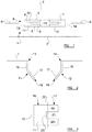
Figure 1 shows a step in production of a housing embodying the present invention; -
Figure 2 shows a cut-away view of a part of a housing embodying the present invention; -
Figure 3 shows a close-up view of one of the tabs offigure 2 ; -
Figure 4 shows a connector suitable for connection with housing embodying the present invention; -
Figure 5 shows a combination of a housing and a connector embodying the present invention; -
Figure 6 shows a further view of the connector offigure 4 , along with a PCB; and -
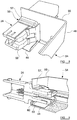
Figures 7 ,8 and 9 show a connection element embodying the present invention. - Embodiments of the invention involve a main body, which is formed from a robust material such as metal. The main body may, for example, be formed from steel, aluminium or another suitable material. Referring firstly to
figure 1 , aside wall 1 of a main body is shown, during production of a finished housing embodying the present inventories. Theside wall 1 extends between atop wall 2 andbottom wall 3, as will be described in more detail below. - First and
second cuts side wall 1. The first andsecond cuts second cuts - The length of each of the first and
second cuts - Two
bridging cuts second cuts first bridging cut second cuts first bridging cut 6 extends generally directly between the first andsecond cuts rectangular tongue 9 which extends toward, but does not reach, the first end 8. Thetongue 9 is defined by regions of thefirst bridging cut 6 that extend generally parallel to the first andsecond cuts tongue 9 has a generallystraight end portion 10, which is preferably substantially perpendicular to the first andsecond cuts - The
second bridging cut 7 is closer to a second, opposite end of the first andsecond cuts first bridging cut 6. The twobridging cuts second cuts - As can be seen in
figure 1 , there is a generallycross-shaped region 10 defined between the first andsecond cuts second bridging cuts side wall 1 and will be removed. - The
cuts second tabs side wall 1 alonghinge regions figure 1 . Thehinge regions first cuts - In the example shown, each
tab tab -
Figure 2 shows a schematic cutaway view of theside wall 1, taken through the line indicated by A-A infigure 1 . In this view, the first andsecond tabs hinge regions side wall 1. In the example shown thetabs hinged regions hinged regions - Each tab has a
first portion 16, which is adjacent to the appropriatehinged region side wall 1. - Each
tab second portion 17, furthest from thehinge regions first region 16. In preferred embodiments, thesecond portion 17 of eachtab side wall 1. To put it another way, thesecond portion 17 of eachtab 11 is preferably set at an angle of 75° to the plane of theside wall 1. - In preferred embodiments, the first and
second portions tab tab second portions second portions tab - Each of the
second portions 17 terminates in a respectivefree end 18. -
Figure 3 shows a schematic view of thefirst tab 11, bent inwardly around thehinge region 13. As can be understood fromfigure 1 , thefirst tab 11 has a generally forked shape, having first and second protruding tongues, 19, 20, which are preferably generally rectangular in shape. A cut-outsection 21, which is also generally rectangular in shape, exists between thetongues first tab 11 is generally "C"-shaped. - As can be understood from
figure 2 , a bend 22 is formed in thefirst tab 11 between thefirst portion 16 andsecond portion 17 thereof. Preferably, the bend 22 is formed at a distance from thehinge 13 such that the bend is formed only in the first andsecond tongues hinge region 13 than theinner end 23 of the cut-outsection 21. - This need not be the case, however, and in other embodiments the bend 22 could be formed closer to the
hinge region 13 than theinner end 23 of the cut outsection 21. -
Figure 4 shows aconnector 24 which is adapted to be connected to the connection aperture 15 formed as described above. Theconnector 24 comprises a generally elongatemain body 25, having electrically conductingconnectors 26 running therethrough. Theconnector 24 has a generallytransverse flange portion 27 part-way along its length, which protrudes from both sides of themain body 25. In operation, afront surface 28 theflange portion 27 will abut against the outer surface of theside wall 1 of the main body. - The
connector 24 includes anengagement portion 29, which protrudes forwardly from theflange portion 27 and which, in use, is intended to lie within the main body, i.e. on the interior side ofside wall 1. - An
initial portion 30 of theengagement portion 29 includes generally straight, parallel outer side walls, which are generally parallel with a longitudinal axis of theconnector 24. Asecond portion 31, further from theflange portion 27 than theinitial portion 30, is narrower than thefirst portion 30. - The
connection portion 29 terminates in a third, widenedportion 32. Between thesecond portion 31 and the third, widenedportion 32, a pair of rearward-facingshoulders 34 are formed, one on each side of theconnector 24. In the example shown infigure 4 , aninner portion 35 of the shoulder is set at a relatively steep angle (in the example shown, around 45°) to the longitudinal axis of theconnector 24. Anouter portion 36 of theshoulder 34 is set to be perpendicular or almost perpendicular to the longitudinal axis of the connector. In preferred embodiments, the angle of theouter portion 36 of theshoulder 34 generally matches the angle at which thesecond portion 17 of eachtab side wall 1. Therefore, in this example, theouter section 36 of theshoulder 34 is set at around 75° to the longitudinal axis of theconnector 24. - Forwardly of the shoulder, the third, widened
portion 32 hasside walls 37 which are generally straight and parallel with the longitudinal axis of theconnector 24, although at its forward-most portion theside wall 37 terminates in an inwardly-taperedportion 38. Theengagement portion 29 terminates in a generallyflat end wall 39, which is perpendicular or substantially perpendicular to the longitudinal axis to theconnector 24. - Engagement of the
connector 24 with theside wall 1 will now be described. - The widths of the third, widened
portion 32, and of thefirst portion 30, of theengagement portion 29 are approximately the same as, or slightly less than, the width of the connection aperture 15. - As the forward-most part of the
engagement portion 29 is inserted into the connection aperture 15, the third, widenedportion 32 passes through the connection aperture 15, and contact the inwardly-deflectedsecond portions 17 of thetabs tabs connection portion 29 is introduced, and this is assisted by the taperedportions 38 formed near the end of theconnection portion 29. - Once the third, widened
portion 32 of theconnection portion 29 has been pushed all the way past the free ends 18 of thetabs tabs shoulders 34 formed between the second andthird portions connection portion 29. At this point, thefront surface 28 of theflange portion 27 is abutted against the outer surface of theside wall 1. It will therefore be understood that the distance from thefront surface 28 of theflange portion 27 to the rearward-facingshoulders 34 is approximately the same as, or slightly greater than, the distance from the outer surface of theside wall 1 and thefree end 18 of eachtab - It will be understood that, once the
connector 24 has been inserted in this way, it will not be possible to remove theconnector 24 from theside wall 1 by simply pulling it directly away from theside wall 1, as thetabs shoulders 34 of theconnection portion 29, thereby resisting this movement. - This arrangement is shown in
figure 5 . As can be seen in this figure, the side walls of thefirst portion 30 of theconnection portion 29 lie against the inner surfaces of thefirst portion 16 of eachtab connector 24 with respect to theside wall 1. Although not visible in this figure, the height of thefirst portion 30 of theconnector 24 also matches closely the height of the connection aperture 15, and so motion of theconnector 24 with respect to theside wall 1 in a direction generally parallel with theside wall 1 but perpendicular to the width of the connection aperture 15 will also be strongly resisted. - With reference to
figure 6 , a perspective view of theconnector 24 is shown. As can be seen in this figure, in preferred embodiments the third, widenedportion 32 of theconnector portion 29 has spaced apart first andsecond layers 33, 34, each of which has the external shape shown infigure 4 , having first, second andthird portions second layers 33, 34. - As the skilled reader will appreciate, with this design one of each of
tongues tabs shoulder 34 of the respective first andsecond layers - Also visible in
figure 6 is aPCB 42, which will be housed within the main body. ThePCB 42 is (in this example) generally rectangular in shape, and has a series of slidingconnectors 43 formed on one side thereof. The first andsecond layers PCB 42 can fit between the layers. Preferably, thePCB 42 fits snugly between thelayers layers PCB 42. Thelayers connectors 43 of thePCB 42, to help hold thePCB 42 in place with respect to theconnector 24. - In use, the
connector 24 will provide a power and/or data connection between thePCB 42 and the exterior of the main body. Theelectrically conducting connectors 26 which run through theconnector 24 contact electrical connectors on thePCB 42 for this purpose. The electrical connectors on thePCB 42 are preferably formed as part of the slidingconnectors 43. - In embodiments of the invention, the
PCB 42 is firmly mounted within the main body such that, when theconnector 24 is connected to the main body in the manner described above, theconnector 24 cooperates and connects with thePCB 42. This allows for a simple and robust connection (without any intermediate connectors between theconnector 24 and thePCB 42 being needed), and also allows an efficient use of space within the main body. - The separated first and
second levels connector 24, along with the forked shape of thetabs connector 24 and thePCB 42, as the edge of thePCB 42 can fit between thelayers tongues tab - In other embodiments, however, the tabs may have a shape which is rectangular or substantially rectangular, without the forked design shown in
figures 3 and5 . In these embodiments, the connection portion of the connector may not involve the design shown infigure 6 , involving first and secondseparated layers - In practice, the
side wall 1 may form part of a housing, which defines a generally enclosed space in which one or more electronic components may be provided. The housing may, in some embodiments, comprise a metal component which provides a substantially enclosed space aside from one open surface, for instance providing top, bottom, side and rear walls, but no front wall. A plastic retaining wall may be attached to the open end of the housing, using any suitable means to provide an entirely or substantially enclosed space within the housing. A construction of this type may be suitable for a radar sensor, where the plastic side of the housing allows the radar signal to pass through. - In other embodiments the housing may be formed entirely from metal walls to form an entirely or substantially enclosed space. The skilled reader will understand that the housing may take any suitable form, and need not have any particular (such as oblong) shape.
- A connection aperture 15 is formed in one of the metal walls of the housing, as described above. While the formation of the connection aperture 15 above is particularly described in relation to a side wall, this is not necessarily the case and the connection aperture may be formed in any appropriate surface of the housing. In some examples the wall of the housing in which the connection aperture 15 is formed is entirely or partially curved, and references to the plane of the wall in which the connection aperture is formed should be interpreted as references to the plane of the wall at the point where the connection aperture is formed.
- Once the connection aperture 15 has been formed, a
connector 24 may then be inserted into the connection aperture 15 so that it is firmly held in place, as discussed above. The electronic components held within the housing may then communicate with the exterior of the housing through electrical connectors (such as theelectrical connectors 27 shown infigures 4 and 5 ). - It will be understood that the formation of a connection aperture of this type provides several advantages. Firstly, the formation of the
tabs - The connection itself is also effective. Once inserted in place as shown in
figure 5 , theconnector 24 may not move laterally with respect to theside wall 1, either in the left-right or up-down direction, as surfaces of theconnector 24 are abutted against inward-facing surfaces of the connection aperture 15. Moreover, theconnector 24 may not be removed directly outwardly from the housing, because the free ends 18 of thetabs shoulders 34 of theconnection member 29. -
Figure 7 ,8 and 9 show asalternative connection element 43 in accordance with the present invention. - With reference to
figure 7 , theconnection element 43 comprises abaseplate 44 which is, in the example shown, generally planar and rectangular. At first and second opposing ends 45, 46 of thebaseplate 44,side portions baseplate 44. Theside portions tabs sidewall 1, as described above. Eachside portion flat portion 49 which is arranged to be perpendicular or substantially perpendicular to the plane of thebaseplate 44. Eachside portion second portion 50, which is deflected inwardly, away from the plane of thefirst portion 49, towards the other of theside portions - Each of the first, generally
flat portions 49 has an edge, furthest from the respectivesecond portion 50, which is preferably aligned or substantially aligned with a front edge 59 of thebaseplate 44, which extends between the first and second opposing ends 45, 46 thereof. - Each
second portion 50 is also shaped to be in a "forked" configuration as is the case for thetabs - In contrast to the
tabs distal end 51 of each of the forked portions is turned back on itself, by being bent outwardly (i.e. away from the other one of theside portions 47, 48). In the example shown, each of the forked portions is curved through 180°, and terminates in ashort end portion 52 which lies parallel or substantially parallel with the main part of the forked portion. - Finally, short,
upstanding skirts 53 are provided at the first and second ends 45, 46 of thebase plate 44, and also on the front edge 59 thereof. - In preferred embodiments the
connection element 43 is formed from a single sheet of a robust material such as steel. The sheet is initially planar and is cut, stamped or otherwise formed into the correct shape, and then bent into the configuration shown infigure 7 . In particular, pieces of the sheet to the sides of thebaseplate 44 are bent to form the first andsecond tabs skirts 53 that are formed at the first and second ends, 45, 46 and front edge 59 of thebaseplate 44. -
Figures 8 and 9 show views of theconnection element 43 in use with ahousing 54, which has awall 55 with aconnection aperture 56 formed therethrough. An inward-facinglip 57 is, in this embodiment, formed all of the way around theaperture 56. Theconnection element 43 is placed around theaperture 56 so that thebaseplate 44 thereof lies on abottom surface 58 of the housing, and thetabs aperture 56. - As can be seen in
figure 9 , along the lower side of theconnection aperture 56 the inward-facinglip 57 curves inwardly so that, at its free end, it lies parallel or substantially parallel with thebottom surface 58 of the housing. The free end of the inward-facinglip 57 preferably comprises a short, generally straight holdingsection 60. - As discussed above, the
connection element 43 has a short,upstanding skirt 53 are provided on its front edge 59. In preferred embodiments, the height of theskirt 53 at the front edge 59 of theconnection element 43 is substantially the same as, or slightly greater than, the distance between thebottom surface 58 of the housing and the free end of the inward-facinglip 57. - As can be seen in
figure 9 , during assembly theskirt 53 at the front edge 59 of theconnection element 43 is positioned between thebottom surface 58 of the housing and the free end of the inward-facinglip 57, so that it is clamped or otherwise held firmly between thebottom surface 58 of the housing and the free end of the inward-facinglip 57. - In preferred embodiments, this will hold the
connection element 43 in place with respect to the housing, theskirt 53 will be held in place sufficiently firmly to resist movement of theconnection element 43 in a direction parallel with thebottom surface 58 of the housing when a connector is inserted into theconnection aperture 56. Rotational motion of theconnection element 43 about its front edge 59 will also be strongly resisted as a result of thebaseplate 44 of theconnection element 43 lying against thebottom surface 58 of the housing. - In the above example the skirt is clamped between the lip and the bottom wall of the housing. In other embodiments, however, the skirt may be clamped between a suitable lip and another wall of the housing, for instance a side wall or top wall. Indeed, the connection element may have two or more skirts which are clamped against respective different walls of the housing by suitable lips surrounding the connection aperture.
- Alternatively, or in addition, the connection element may be rigidly connected to the interior of the main body, for instance by welding. In particular, the
baseplate 44 may be connected to thebottom surface 58 of themain body 54. - As the
connector 24 is pushed through theaperture 56, thetabs connector 24 in the same manner as thetabs - The fact that the distal ends of the forked portions are turned back on themselves leads to increased robustness of the
tabs - The
connection element 43 may be useful in situations where it is desired for the tabs to be formed of a material that is more flexible than the material that forms the main body. The main body may need to be very strong and robust, and to be able to withstand heavy wear and sharp impacts. The material from which the walls of the main unit are formed may therefore necessarily be very strong and rigid. In this case, having tabs which are stamped out of the material of the wall itself may be inappropriate, because these tabs will not be sufficiently flexible. - For instance, it may be desirable for the main unit to be formed from steel (or another suitable material) having a high ductility, to allow the main unit to be formed using a deep-drawing or similar process. However, steel of this kind may not be ideal for forming the tabs, and it may be preferable to form the tabs from spring steel, or another material having a high yield strength. Therefore, the provision of a separate connection element allows these parts of the housing to be formed from different materials which are each well-suited to their respective purposes.
- The presence of the
baseplate 44 in theconnection element 43 allows theconnection element 43 to be firmly and reliably connected to the interior of the main body. - In addition, the edge of each first, generally
flat portions 49 of eachside portion connection element 43 is installed, be against or close to the interior of thewall 55 of the main body, to the side of theconnection aperture 56. Theside portions connector 24 from theconnection aperture 56. - Although the embodiment described above includes a
single connection element 43 that has bothside portions - When used in this specification and claims, the terms "comprises" and "comprising" and variations thereof mean that the specified features, steps or integers are included. The terms are not to be interpreted to exclude the presence of other features, steps or components.
- The features disclosed in the foregoing description, or the following claims, or the accompanying drawings, expressed in their specific forms or in terms of a means for performing the disclosed function, or a method or process for attaining the disclosed result, as appropriate, may, separately, or in any combination of such features, be utilised for realising the invention in diverse forms thereof.
Claims (15)
- A housing suitable for containing one or more electronic components, the housing having a connection aperture formed in a wall thereof to allow connection of a cable to the wall, wherein the connection aperture is provided with a pair of tabs positioned on opposing sides thereof, each tab being generally elongate and having a free end, each tab being deflected with respect to the wall and extending inwardly into the interior of the housing at an angle to the plane of the wall, so the free end of each tab lies within the housing, and wherein each tab has a first region, which is near or adjacent the wall, which extends at a first angle with respect to the plane of the wall, and a second region, which is further from the wall that the first region, which extends at a second angle with respect to the plane of the wall, the second angle being less than the first angle.
- A housing according to claim 1, wherein the tabs are cut out from the wall of the housing, and is attached to the wall of the housing at an attachment region.
- A housing according to claim 1, wherein the tabs are provided on one or more separate connection elements, which are attached to the interior of the housing.
- A housing according to any preceding claim, wherein the first region extends at an angle of around 90° with respect to the plane of the wall, and the second region extends, at its free end, in a direction which has a component pointing towards the other of the tabs.
- A housing according to any preceding claim wherein each tab has a shape which includes a pair of substantially parallel tongues extending away from the attachment region, there being a cut out region between the tongues.
- A housing according to any preceding claim, wherein the housing defines a generally substantially enclosed interior, aside from the connection aperture.
- A housing according to any preceding claim, wherein the height of each tab is at least 80% of the height of the connection aperture, and is preferably at least 90% of the height of the connection aperture.
- A housing according to any preceding claim in combination with a connector which is sized to fit into the connection aperture to provide an electrical connection between the interior of the housing and the exterior of the housing, wherein the connector has a leading end and a pair of rearwardly-facing shoulders formed behind the leading end, the connector being dimensioned so that, when the leading end of the connector is inserted into the connection aperture, the tabs are initially deflected outwardly from their resting positions by the leading end, but then return to their resting positions where the free end of the tabs lie against the respective rearwardly-facing shoulders of the connector.
- A housing and connector according to claim 8, wherein the connector further comprises an outwardly-extending flange region, the flange region being spaced from the rearwardly-facing shoulders such that, when the connector is inserted into the connection aperture, when the free end of the tabs rest against the respective rearwardly-facing shoulders of the connector, a front surface of the flange portion lies against or adjacent an outer surface of the wall of the housing.
- A method of forming a connection aperture in a wall of a housing, comprising the steps of:forming one or more cuts in a wall of the housing to form a pair of tabs, each tab being generally elongate and being attached to the housing at an attachment region, and having a free end; anddeflecting each tab at or near the attachment region with respect to the wall so that each tab extends inwardly into the interior of the housing at an angle to the plane of the wall, so the free end of each tab lies within the housing, and wherein each tab has a first region, which is near or adjacent the attachment region, which extends at a first angle with respect to the plane of the wall, and a second region, which is further from the attachment region that the first region, which extends at a second angle with respect to the plane of the wall, the second angle being less than the first angle.
- A method according to claim 10, wherein the step of deflecting each tab includes the step of deflecting each tab so that the first region extends at an angle of around 90° with respect to the plane of the wall, and the second region extends at its free end, in a direction which has a component point pointing towards the other of the tabs.
- A method according to claim 10 or 11, wherein the step of forming cuts in the wall of the housing to form a pair of tabs comprises forming cuts so that each tab has a shape which includes a pair of substantially parallel tongues extending away from the attachment region, there being a cut-out region between the tongues.
- A method according to any one of claims 10 to 12, where the connection aperture is formed in the wall of a housing which defines a generally substantially enclosed interior, aside from the connection aperture.
- A method according to any one of claims 10 to 13, wherein the step of forming cuts in the wall of the housing to form a pair of tabs comprises forming cuts such that the height of each tab is at least 80% of the height of the connection aperture, and is preferably at least 90% of the height of connection aperture.
- A method of forming a connection aperture in a wall of a housing, comprising the steps of:forming an aperture in the wall of the housing;providing one or more connection elements having a pair of tabs which are generally elongate and have a free end; andattaching the one or more connection elements to the interior of the housing so that the tabs lie on either side of the aperture, each tab being deflected with respect to the wall and extending inwardly into the interior of the housing at an angle to the plane of the wall, so that free end of each tab lies within the housing, and wherein each tab has a first region, which is near or adjacent the wall, which extends to the first angle with respect to the plane of the wall, and a second region, which is further from the wall than the first region, which extends at a second angle with respect to the plane of the wall, the second angle being less than the first angle.
Priority Applications (1)
| Application Number | Priority Date | Filing Date | Title |
|---|---|---|---|
| EP16196038.0A EP3316668B1 (en) | 2016-10-27 | 2016-10-27 | A housing unit |
Applications Claiming Priority (1)
| Application Number | Priority Date | Filing Date | Title |
|---|---|---|---|
| EP16196038.0A EP3316668B1 (en) | 2016-10-27 | 2016-10-27 | A housing unit |
Publications (2)
| Publication Number | Publication Date |
|---|---|
| EP3316668A1 true EP3316668A1 (en) | 2018-05-02 |
| EP3316668B1 EP3316668B1 (en) | 2020-04-08 |
Family
ID=57209281
Family Applications (1)
| Application Number | Title | Priority Date | Filing Date |
|---|---|---|---|
| EP16196038.0A Active EP3316668B1 (en) | 2016-10-27 | 2016-10-27 | A housing unit |
Country Status (1)
| Country | Link |
|---|---|
| EP (1) | EP3316668B1 (en) |
Citations (5)
| Publication number | Priority date | Publication date | Assignee | Title |
|---|---|---|---|---|
| US4124267A (en) * | 1977-08-08 | 1978-11-07 | Trw Inc. | Mounting clip for a connector |
| DE10162405A1 (en) * | 2001-12-19 | 2003-07-10 | Hella Kg Hueck & Co | Plug connector has lug accommodation region into which printed circuit board protrudes with at least one contact pad within this region for electrical connection to plug |
| US6657869B1 (en) | 1999-03-17 | 2003-12-02 | Trw Automotive Electronics & Components Gmbh & Co. Kg | Metal housing, especially for an airbag control device |
| US20090042439A1 (en) * | 2007-08-10 | 2009-02-12 | Hong Fu Jin Precision Industry (Shenzhen) Co., Ltd. | Computer enclosure with connector |
| US8657622B1 (en) * | 2012-09-20 | 2014-02-25 | Hong Fu Jin Precision Industry (Shenzhen) Co., Ltd | Electrical connector assembly |
-
2016
- 2016-10-27 EP EP16196038.0A patent/EP3316668B1/en active Active
Patent Citations (5)
| Publication number | Priority date | Publication date | Assignee | Title |
|---|---|---|---|---|
| US4124267A (en) * | 1977-08-08 | 1978-11-07 | Trw Inc. | Mounting clip for a connector |
| US6657869B1 (en) | 1999-03-17 | 2003-12-02 | Trw Automotive Electronics & Components Gmbh & Co. Kg | Metal housing, especially for an airbag control device |
| DE10162405A1 (en) * | 2001-12-19 | 2003-07-10 | Hella Kg Hueck & Co | Plug connector has lug accommodation region into which printed circuit board protrudes with at least one contact pad within this region for electrical connection to plug |
| US20090042439A1 (en) * | 2007-08-10 | 2009-02-12 | Hong Fu Jin Precision Industry (Shenzhen) Co., Ltd. | Computer enclosure with connector |
| US8657622B1 (en) * | 2012-09-20 | 2014-02-25 | Hong Fu Jin Precision Industry (Shenzhen) Co., Ltd | Electrical connector assembly |
Also Published As
| Publication number | Publication date |
|---|---|
| EP3316668B1 (en) | 2020-04-08 |
Similar Documents
| Publication | Publication Date | Title |
|---|---|---|
| US10069233B2 (en) | Female terminal having an outwardly bulging lance locking portion on a folded U-shaped plate | |
| KR101752265B1 (en) | A cramping fastener device | |
| US20070093131A1 (en) | Connector | |
| US6227915B1 (en) | Female terminal fitting | |
| EP3573189B1 (en) | Connector | |
| US20090053916A1 (en) | Connector | |
| EP2677606A1 (en) | Latching structure for shielded connector | |
| KR20170091732A (en) | Electric wire housing protector | |
| JP5060849B2 (en) | connector | |
| CN112771729A (en) | Connector with a locking member | |
| CN101689415A (en) | Grommet | |
| JP4285318B2 (en) | connector | |
| CN105284011A (en) | Female terminal | |
| US10856428B2 (en) | Rattling prevention structure, electronic component module, electrical connection box, and wire harness | |
| US8601650B2 (en) | Attachment structure of clip | |
| EP2511985A1 (en) | Board connector and method of producing a fixing member therefor | |
| MX2008003851A (en) | Electrical connector having lever with protective shroud. | |
| WO2017006493A1 (en) | Wire housing protector | |
| EP3579347B1 (en) | Terminal assembly and connector | |
| JP2007149504A (en) | Female terminals and connectors | |
| JP4885638B2 (en) | Protector | |
| EP3316668B1 (en) | A housing unit | |
| CN111755895B (en) | Connector with a locking member | |
| US6561837B1 (en) | Insulation displacement connector | |
| JP5412997B2 (en) | Electrical junction box |
Legal Events
| Date | Code | Title | Description |
|---|---|---|---|
| PUAI | Public reference made under article 153(3) epc to a published international application that has entered the european phase |
Free format text: ORIGINAL CODE: 0009012 |
|
| STAA | Information on the status of an ep patent application or granted ep patent |
Free format text: STATUS: THE APPLICATION HAS BEEN PUBLISHED |
|
| AK | Designated contracting states |
Kind code of ref document: A1 Designated state(s): AL AT BE BG CH CY CZ DE DK EE ES FI FR GB GR HR HU IE IS IT LI LT LU LV MC MK MT NL NO PL PT RO RS SE SI SK SM TR |
|
| AX | Request for extension of the european patent |
Extension state: BA ME |
|
| STAA | Information on the status of an ep patent application or granted ep patent |
Free format text: STATUS: REQUEST FOR EXAMINATION WAS MADE |
|
| 17P | Request for examination filed |
Effective date: 20181031 |
|
| RBV | Designated contracting states (corrected) |
Designated state(s): AL AT BE BG CH CY CZ DE DK EE ES FI FR GB GR HR HU IE IS IT LI LT LU LV MC MK MT NL NO PL PT RO RS SE SI SK SM TR |
|
| RAP1 | Party data changed (applicant data changed or rights of an application transferred) |
Owner name: VEONEER SWEDEN AB |
|
| GRAP | Despatch of communication of intention to grant a patent |
Free format text: ORIGINAL CODE: EPIDOSNIGR1 |
|
| STAA | Information on the status of an ep patent application or granted ep patent |
Free format text: STATUS: GRANT OF PATENT IS INTENDED |
|
| INTG | Intention to grant announced |
Effective date: 20200108 |
|
| GRAS | Grant fee paid |
Free format text: ORIGINAL CODE: EPIDOSNIGR3 |
|
| GRAA | (expected) grant |
Free format text: ORIGINAL CODE: 0009210 |
|
| STAA | Information on the status of an ep patent application or granted ep patent |
Free format text: STATUS: THE PATENT HAS BEEN GRANTED |
|
| AK | Designated contracting states |
Kind code of ref document: B1 Designated state(s): AL AT BE BG CH CY CZ DE DK EE ES FI FR GB GR HR HU IE IS IT LI LT LU LV MC MK MT NL NO PL PT RO RS SE SI SK SM TR |
|
| REG | Reference to a national code |
Ref country code: CH Ref legal event code: EP Ref country code: AT Ref legal event code: REF Ref document number: 1256170 Country of ref document: AT Kind code of ref document: T Effective date: 20200415 |
|
| REG | Reference to a national code |
Ref country code: DE Ref legal event code: R096 Ref document number: 602016033439 Country of ref document: DE |
|
| REG | Reference to a national code |
Ref country code: IE Ref legal event code: FG4D |
|
| REG | Reference to a national code |
Ref country code: NL Ref legal event code: MP Effective date: 20200408 |
|
| REG | Reference to a national code |
Ref country code: LT Ref legal event code: MG4D |
|
| PG25 | Lapsed in a contracting state [announced via postgrant information from national office to epo] |
Ref country code: NL Free format text: LAPSE BECAUSE OF FAILURE TO SUBMIT A TRANSLATION OF THE DESCRIPTION OR TO PAY THE FEE WITHIN THE PRESCRIBED TIME-LIMIT Effective date: 20200408 Ref country code: SE Free format text: LAPSE BECAUSE OF FAILURE TO SUBMIT A TRANSLATION OF THE DESCRIPTION OR TO PAY THE FEE WITHIN THE PRESCRIBED TIME-LIMIT Effective date: 20200408 Ref country code: NO Free format text: LAPSE BECAUSE OF FAILURE TO SUBMIT A TRANSLATION OF THE DESCRIPTION OR TO PAY THE FEE WITHIN THE PRESCRIBED TIME-LIMIT Effective date: 20200708 Ref country code: FI Free format text: LAPSE BECAUSE OF FAILURE TO SUBMIT A TRANSLATION OF THE DESCRIPTION OR TO PAY THE FEE WITHIN THE PRESCRIBED TIME-LIMIT Effective date: 20200408 Ref country code: IS Free format text: LAPSE BECAUSE OF FAILURE TO SUBMIT A TRANSLATION OF THE DESCRIPTION OR TO PAY THE FEE WITHIN THE PRESCRIBED TIME-LIMIT Effective date: 20200808 Ref country code: PT Free format text: LAPSE BECAUSE OF FAILURE TO SUBMIT A TRANSLATION OF THE DESCRIPTION OR TO PAY THE FEE WITHIN THE PRESCRIBED TIME-LIMIT Effective date: 20200817 Ref country code: GR Free format text: LAPSE BECAUSE OF FAILURE TO SUBMIT A TRANSLATION OF THE DESCRIPTION OR TO PAY THE FEE WITHIN THE PRESCRIBED TIME-LIMIT Effective date: 20200709 Ref country code: LT Free format text: LAPSE BECAUSE OF FAILURE TO SUBMIT A TRANSLATION OF THE DESCRIPTION OR TO PAY THE FEE WITHIN THE PRESCRIBED TIME-LIMIT Effective date: 20200408 |
|
| REG | Reference to a national code |
Ref country code: AT Ref legal event code: MK05 Ref document number: 1256170 Country of ref document: AT Kind code of ref document: T Effective date: 20200408 |
|
| PG25 | Lapsed in a contracting state [announced via postgrant information from national office to epo] |
Ref country code: LV Free format text: LAPSE BECAUSE OF FAILURE TO SUBMIT A TRANSLATION OF THE DESCRIPTION OR TO PAY THE FEE WITHIN THE PRESCRIBED TIME-LIMIT Effective date: 20200408 Ref country code: HR Free format text: LAPSE BECAUSE OF FAILURE TO SUBMIT A TRANSLATION OF THE DESCRIPTION OR TO PAY THE FEE WITHIN THE PRESCRIBED TIME-LIMIT Effective date: 20200408 Ref country code: RS Free format text: LAPSE BECAUSE OF FAILURE TO SUBMIT A TRANSLATION OF THE DESCRIPTION OR TO PAY THE FEE WITHIN THE PRESCRIBED TIME-LIMIT Effective date: 20200408 Ref country code: BG Free format text: LAPSE BECAUSE OF FAILURE TO SUBMIT A TRANSLATION OF THE DESCRIPTION OR TO PAY THE FEE WITHIN THE PRESCRIBED TIME-LIMIT Effective date: 20200708 |
|
| PG25 | Lapsed in a contracting state [announced via postgrant information from national office to epo] |
Ref country code: AL Free format text: LAPSE BECAUSE OF FAILURE TO SUBMIT A TRANSLATION OF THE DESCRIPTION OR TO PAY THE FEE WITHIN THE PRESCRIBED TIME-LIMIT Effective date: 20200408 |
|
| REG | Reference to a national code |
Ref country code: DE Ref legal event code: R097 Ref document number: 602016033439 Country of ref document: DE |
|
| PG25 | Lapsed in a contracting state [announced via postgrant information from national office to epo] |
Ref country code: IT Free format text: LAPSE BECAUSE OF FAILURE TO SUBMIT A TRANSLATION OF THE DESCRIPTION OR TO PAY THE FEE WITHIN THE PRESCRIBED TIME-LIMIT Effective date: 20200408 Ref country code: RO Free format text: LAPSE BECAUSE OF FAILURE TO SUBMIT A TRANSLATION OF THE DESCRIPTION OR TO PAY THE FEE WITHIN THE PRESCRIBED TIME-LIMIT Effective date: 20200408 Ref country code: CZ Free format text: LAPSE BECAUSE OF FAILURE TO SUBMIT A TRANSLATION OF THE DESCRIPTION OR TO PAY THE FEE WITHIN THE PRESCRIBED TIME-LIMIT Effective date: 20200408 Ref country code: SM Free format text: LAPSE BECAUSE OF FAILURE TO SUBMIT A TRANSLATION OF THE DESCRIPTION OR TO PAY THE FEE WITHIN THE PRESCRIBED TIME-LIMIT Effective date: 20200408 Ref country code: EE Free format text: LAPSE BECAUSE OF FAILURE TO SUBMIT A TRANSLATION OF THE DESCRIPTION OR TO PAY THE FEE WITHIN THE PRESCRIBED TIME-LIMIT Effective date: 20200408 Ref country code: DK Free format text: LAPSE BECAUSE OF FAILURE TO SUBMIT A TRANSLATION OF THE DESCRIPTION OR TO PAY THE FEE WITHIN THE PRESCRIBED TIME-LIMIT Effective date: 20200408 Ref country code: AT Free format text: LAPSE BECAUSE OF FAILURE TO SUBMIT A TRANSLATION OF THE DESCRIPTION OR TO PAY THE FEE WITHIN THE PRESCRIBED TIME-LIMIT Effective date: 20200408 Ref country code: ES Free format text: LAPSE BECAUSE OF FAILURE TO SUBMIT A TRANSLATION OF THE DESCRIPTION OR TO PAY THE FEE WITHIN THE PRESCRIBED TIME-LIMIT Effective date: 20200408 |
|
| PGFP | Annual fee paid to national office [announced via postgrant information from national office to epo] |
Ref country code: GB Payment date: 20201028 Year of fee payment: 5 Ref country code: FR Payment date: 20201028 Year of fee payment: 5 |
|
| PLBE | No opposition filed within time limit |
Free format text: ORIGINAL CODE: 0009261 |
|
| STAA | Information on the status of an ep patent application or granted ep patent |
Free format text: STATUS: NO OPPOSITION FILED WITHIN TIME LIMIT |
|
| PG25 | Lapsed in a contracting state [announced via postgrant information from national office to epo] |
Ref country code: SK Free format text: LAPSE BECAUSE OF FAILURE TO SUBMIT A TRANSLATION OF THE DESCRIPTION OR TO PAY THE FEE WITHIN THE PRESCRIBED TIME-LIMIT Effective date: 20200408 Ref country code: PL Free format text: LAPSE BECAUSE OF FAILURE TO SUBMIT A TRANSLATION OF THE DESCRIPTION OR TO PAY THE FEE WITHIN THE PRESCRIBED TIME-LIMIT Effective date: 20200408 |
|
| 26N | No opposition filed |
Effective date: 20210112 |
|
| PG25 | Lapsed in a contracting state [announced via postgrant information from national office to epo] |
Ref country code: SI Free format text: LAPSE BECAUSE OF FAILURE TO SUBMIT A TRANSLATION OF THE DESCRIPTION OR TO PAY THE FEE WITHIN THE PRESCRIBED TIME-LIMIT Effective date: 20200408 |
|
| REG | Reference to a national code |
Ref country code: CH Ref legal event code: PL |
|
| PG25 | Lapsed in a contracting state [announced via postgrant information from national office to epo] |
Ref country code: MC Free format text: LAPSE BECAUSE OF FAILURE TO SUBMIT A TRANSLATION OF THE DESCRIPTION OR TO PAY THE FEE WITHIN THE PRESCRIBED TIME-LIMIT Effective date: 20200408 Ref country code: LU Free format text: LAPSE BECAUSE OF NON-PAYMENT OF DUE FEES Effective date: 20201027 |
|
| REG | Reference to a national code |
Ref country code: BE Ref legal event code: MM Effective date: 20201031 |
|
| PG25 | Lapsed in a contracting state [announced via postgrant information from national office to epo] |
Ref country code: CH Free format text: LAPSE BECAUSE OF NON-PAYMENT OF DUE FEES Effective date: 20201031 Ref country code: BE Free format text: LAPSE BECAUSE OF NON-PAYMENT OF DUE FEES Effective date: 20201031 Ref country code: LI Free format text: LAPSE BECAUSE OF NON-PAYMENT OF DUE FEES Effective date: 20201031 |
|
| PG25 | Lapsed in a contracting state [announced via postgrant information from national office to epo] |
Ref country code: IE Free format text: LAPSE BECAUSE OF NON-PAYMENT OF DUE FEES Effective date: 20201027 |
|
| REG | Reference to a national code |
Ref country code: DE Ref legal event code: R081 Ref document number: 602016033439 Country of ref document: DE Owner name: ARRIVER SOFTWARE AB, SE Free format text: FORMER OWNER: VEONEER SWEDEN AB, VARGARDA, SE Ref country code: DE Ref legal event code: R082 Ref document number: 602016033439 Country of ref document: DE Representative=s name: WAGNER & GEYER PARTNERSCHAFT MBB PATENT- UND R, DE Ref country code: DE Ref legal event code: R081 Ref document number: 602016033439 Country of ref document: DE Owner name: QUALCOMM AUTO LTD., CAMBRIDGE, GB Free format text: FORMER OWNER: VEONEER SWEDEN AB, VARGARDA, SE |
|
| PG25 | Lapsed in a contracting state [announced via postgrant information from national office to epo] |
Ref country code: TR Free format text: LAPSE BECAUSE OF FAILURE TO SUBMIT A TRANSLATION OF THE DESCRIPTION OR TO PAY THE FEE WITHIN THE PRESCRIBED TIME-LIMIT Effective date: 20200408 Ref country code: MT Free format text: LAPSE BECAUSE OF FAILURE TO SUBMIT A TRANSLATION OF THE DESCRIPTION OR TO PAY THE FEE WITHIN THE PRESCRIBED TIME-LIMIT Effective date: 20200408 Ref country code: CY Free format text: LAPSE BECAUSE OF FAILURE TO SUBMIT A TRANSLATION OF THE DESCRIPTION OR TO PAY THE FEE WITHIN THE PRESCRIBED TIME-LIMIT Effective date: 20200408 |
|
| GBPC | Gb: european patent ceased through non-payment of renewal fee |
Effective date: 20211027 |
|
| PG25 | Lapsed in a contracting state [announced via postgrant information from national office to epo] |
Ref country code: MK Free format text: LAPSE BECAUSE OF FAILURE TO SUBMIT A TRANSLATION OF THE DESCRIPTION OR TO PAY THE FEE WITHIN THE PRESCRIBED TIME-LIMIT Effective date: 20200408 |
|
| PG25 | Lapsed in a contracting state [announced via postgrant information from national office to epo] |
Ref country code: GB Free format text: LAPSE BECAUSE OF NON-PAYMENT OF DUE FEES Effective date: 20211027 |
|
| PG25 | Lapsed in a contracting state [announced via postgrant information from national office to epo] |
Ref country code: FR Free format text: LAPSE BECAUSE OF NON-PAYMENT OF DUE FEES Effective date: 20211031 |
|
| REG | Reference to a national code |
Ref country code: DE Ref legal event code: R081 Ref document number: 602016033439 Country of ref document: DE Owner name: QUALCOMM AUTO LTD., CAMBRIDGE, GB Free format text: FORMER OWNER: ARRIVER SOFTWARE AB, LINKOEPING, SE |
|
| PGFP | Annual fee paid to national office [announced via postgrant information from national office to epo] |
Ref country code: DE Payment date: 20250912 Year of fee payment: 10 |