EP3316575A1 - Procédé de fourniture d'un effet de parallaxe de mouvement continu au moyen d'un afficheur auto-stéréoscopique, dispositif correspondant, produit programme informatique et support lisible par ordinateur - Google Patents
Procédé de fourniture d'un effet de parallaxe de mouvement continu au moyen d'un afficheur auto-stéréoscopique, dispositif correspondant, produit programme informatique et support lisible par ordinateur Download PDFInfo
- Publication number
- EP3316575A1 EP3316575A1 EP16306433.0A EP16306433A EP3316575A1 EP 3316575 A1 EP3316575 A1 EP 3316575A1 EP 16306433 A EP16306433 A EP 16306433A EP 3316575 A1 EP3316575 A1 EP 3316575A1
- Authority
- EP
- European Patent Office
- Prior art keywords
- views
- stereoscopic
- auto
- current
- observer
- Prior art date
- Legal status (The legal status is an assumption and is not a legal conclusion. Google has not performed a legal analysis and makes no representation as to the accuracy of the status listed.)
- Withdrawn
Links
Images


Classifications
-
- H—ELECTRICITY
- H04—ELECTRIC COMMUNICATION TECHNIQUE
- H04N—PICTORIAL COMMUNICATION, e.g. TELEVISION
- H04N13/00—Stereoscopic video systems; Multi-view video systems; Details thereof
- H04N13/20—Image signal generators
- H04N13/282—Image signal generators for generating image signals corresponding to three or more geometrical viewpoints, e.g. multi-view systems
-
- H—ELECTRICITY
- H04—ELECTRIC COMMUNICATION TECHNIQUE
- H04N—PICTORIAL COMMUNICATION, e.g. TELEVISION
- H04N13/00—Stereoscopic video systems; Multi-view video systems; Details thereof
- H04N13/10—Processing, recording or transmission of stereoscopic or multi-view image signals
- H04N13/106—Processing image signals
- H04N13/111—Transformation of image signals corresponding to virtual viewpoints, e.g. spatial image interpolation
-
- G—PHYSICS
- G02—OPTICS
- G02B—OPTICAL ELEMENTS, SYSTEMS OR APPARATUS
- G02B30/00—Optical systems or apparatus for producing three-dimensional [3D] effects, e.g. stereoscopic images
- G02B30/20—Optical systems or apparatus for producing three-dimensional [3D] effects, e.g. stereoscopic images by providing first and second parallax images to an observer's left and right eyes
- G02B30/26—Optical systems or apparatus for producing three-dimensional [3D] effects, e.g. stereoscopic images by providing first and second parallax images to an observer's left and right eyes of the autostereoscopic type
- G02B30/27—Optical systems or apparatus for producing three-dimensional [3D] effects, e.g. stereoscopic images by providing first and second parallax images to an observer's left and right eyes of the autostereoscopic type involving lenticular arrays
-
- H—ELECTRICITY
- H04—ELECTRIC COMMUNICATION TECHNIQUE
- H04N—PICTORIAL COMMUNICATION, e.g. TELEVISION
- H04N13/00—Stereoscopic video systems; Multi-view video systems; Details thereof
- H04N13/10—Processing, recording or transmission of stereoscopic or multi-view image signals
- H04N13/106—Processing image signals
- H04N13/111—Transformation of image signals corresponding to virtual viewpoints, e.g. spatial image interpolation
- H04N13/117—Transformation of image signals corresponding to virtual viewpoints, e.g. spatial image interpolation the virtual viewpoint locations being selected by the viewers or determined by viewer tracking
-
- H—ELECTRICITY
- H04—ELECTRIC COMMUNICATION TECHNIQUE
- H04N—PICTORIAL COMMUNICATION, e.g. TELEVISION
- H04N13/00—Stereoscopic video systems; Multi-view video systems; Details thereof
- H04N13/30—Image reproducers
- H04N13/302—Image reproducers for viewing without the aid of special glasses, i.e. using autostereoscopic displays
- H04N13/305—Image reproducers for viewing without the aid of special glasses, i.e. using autostereoscopic displays using lenticular lenses, e.g. arrangements of cylindrical lenses
-
- H—ELECTRICITY
- H04—ELECTRIC COMMUNICATION TECHNIQUE
- H04N—PICTORIAL COMMUNICATION, e.g. TELEVISION
- H04N13/00—Stereoscopic video systems; Multi-view video systems; Details thereof
- H04N13/30—Image reproducers
- H04N13/349—Multi-view displays for displaying three or more geometrical viewpoints without viewer tracking
- H04N13/351—Multi-view displays for displaying three or more geometrical viewpoints without viewer tracking for displaying simultaneously
-
- H—ELECTRICITY
- H04—ELECTRIC COMMUNICATION TECHNIQUE
- H04N—PICTORIAL COMMUNICATION, e.g. TELEVISION
- H04N13/00—Stereoscopic video systems; Multi-view video systems; Details thereof
- H04N13/30—Image reproducers
- H04N13/366—Image reproducers using viewer tracking
-
- H—ELECTRICITY
- H04—ELECTRIC COMMUNICATION TECHNIQUE
- H04N—PICTORIAL COMMUNICATION, e.g. TELEVISION
- H04N13/00—Stereoscopic video systems; Multi-view video systems; Details thereof
- H04N13/30—Image reproducers
- H04N13/366—Image reproducers using viewer tracking
- H04N13/383—Image reproducers using viewer tracking for tracking with gaze detection, i.e. detecting the lines of sight of the viewer's eyes
-
- H—ELECTRICITY
- H04—ELECTRIC COMMUNICATION TECHNIQUE
- H04N—PICTORIAL COMMUNICATION, e.g. TELEVISION
- H04N13/00—Stereoscopic video systems; Multi-view video systems; Details thereof
- H04N2013/0074—Stereoscopic image analysis
- H04N2013/0085—Motion estimation from stereoscopic image signals
Definitions
- the present disclosure lies in the field of auto-stereoscopic displays. More precisely, the disclosure pertains to a technique for obtaining multi-view images to be displayed on an auto-stereoscopic display.
- the proposed technique allows providing a continuous motion parallax effect, and thus improves the immersive experience of an observer in front of the auto-stereoscopic display.
- Motion parallax offers depth cues by comparing the relative motion of different elements in a 3D scene: when an observer's head moves, closer 3D objects appear to move faster than those far away from the observer.
- Some systems have been proposed to render motion parallax on standard 2D displays or on standard stereoscopic (two-views) displays. For example, some solutions exist to follow the location of an observer in front of the display (e.g. using eye-tracking techniques). It is then possible to render the motion parallax by slightly modifying the content displayed according to the observer's eyes position.
- one main problem of these systems lies in the time it takes to display the adapted content: the location tracking system takes time to evaluate the location of the observer, the adapted content must then be generated accordingly, and finally the display takes time to refresh the content on the screen. This lag between the time the observer is moving his head and the time the adapted content is available on the display is usually too high to be unnoticeable to the observer.
- the observer can have the wrong feeling that an object displayed is moving the opposite way than the one expected, because the brain is anticipating a movement which does not occur quickly enough. The user experience is thus not optimal, and sometime deceptive and discomfortable.
- an example of an auto-stereoscopic display 10 is composed of a standard LCD (Liquid Crystal Display) 11 on top of which a lenticular array 12 has been placed. At a given distance, an observer will only see part of the pixels. For example, observer O1 of figure 1 can only see two sets of pixels, respectively set 2 and set 3, one per eye. If the signal is well constructed, set 2 and set 3 are the two components of a stereoscopic content. In other words, set 2 and set 3 form a stereoscopic pair of views of a same scene, allowing the observer, if well placed, to perceive stereoscopic content without the need for specific equipment such as 3D-glasses.
- LCD Liquid Crystal Display
- An auto-stereoscopic display is usually capable of displaying more than two views at the same time.
- the auto-stereoscopic display 10 is designed to be able to handle eight views at the same time. These eight views are multiplexed into a single image, thus called a multi-view image, displayed on the auto-stereoscopic display.
- a multi-view image to be displayed on an auto-stereoscopic display is generated in a specific way: in particular, the different views of a multi-view image are selected so that they form successive stereoscopic pairs of views.
- figure 1 shows the auto-stereoscopic display 10 displaying a multi-view image I0 comprising eight views V1 to V8. Views V1 to V8 can be observed from several different locations, e.g. from viewing zones Z1, Z2 or Z3.
- observer O1 in viewing zone Z1 and observer 02 in viewing zone Z2 both see exactly the same content, from the same point of view.
- the multi-view image I0 is generated so that the eight views V1 to V8 forms seven successive stereoscopic pairs of views (V1; V2), (V2; V3), (V3; V4), (V4; V5), (V5; V6), (V6; V7), (V7; V8) that are correctly ordered in each viewing zone, i.e. adjacent views are always coherent spatially and temporally within a same viewing zone.
- the motion parallax is well rendered within each viewing zone (Z1, Z2, Z3): if the observer O1 keeps his head moving within the viewing zone Z1, he will enjoy an optimal immersive experience regarding motion parallax.
- one drawback of the previously described technique is that a continuous motion parallax effect is restricted to a very limited zone, i.e. a narrow viewing zone. This is due to the optical properties of the lenticular array 12 previously described. For example, if the observer O3 - initially seeing stereoscopic pair of views (V1; V2) from viewing zone Z3 - moves his head to his right, to a position where he sees stereoscopic pair of views (V7; V8) from viewing zone Z2, he won't see a continuous and coherent motion parallax effect since pairs of views (V1; V2), (V8; V1) and (V7; V8) do not form coherent successive stereoscopic pairs of views.
- a method for obtaining a multi-view image to be displayed on an auto-stereoscopic display is provided.
- the auto-stereoscopic display is configured to display multi-view images comprising n views forming n -1 successive stereoscopic pairs of views.
- the proposed method for obtaining a multi-view image to be displayed comprises:
- the content displayed on the auto-stereoscopic display can be automatically adapted depending on the location of the observer.
- the multi-view image to be displayed on the auto-stereoscopic display is obtained from n views determined so that they form a set of n -1 successive stereoscopic pairs of views centred on the observer location.
- the content displayed on the auto-stereoscopic display may thus be constantly adapted so that the observer is always substantially located at the centre of a zone in which motion parallax effect is respected.
- obtaining said multi-view image to be displayed takes into account said location of the observer in front of said auto-stereoscopic display.
- the multi-view image to be displayed may be generated so that the current stereoscopic pair of views is still associated with the predetermined location of the observer in front of said auto-stereoscopic display. In that way, if the observer hasn't moved again after having reached said predetermined location, he will not notice any undesirable artefact when the image displayed on the auto-stereoscopic display changes to the newly obtained multi-view image: he still sees the scene with the same point of view. Besides, the multi-view image to be displayed may also be generated so that the optical properties of the auto-stereoscopic display are taken into account.
- the multi-view image is generated according to the position of the observer in a way that makes adjacent views always coherent spatially and temporally.
- the observer is sure to see only adjacent and coherent content.
- n is an even number
- the n views being determined responsive to said current stereoscopic pair of views defines a set of n-1 successive stereoscopic pairs of views in which the current stereoscopic pair of views occupies the position of rank n / 2.
- the current stereoscopic pair of views occupies the exact central position within the set of n - 1 successive stereoscopic pairs of views.
- a continuous motion parallax effect is thus provided, whether the observer moves his head to his right or to his left.
- n is an odd number
- the n views being determined responsive to said current stereoscopic pair of views defines a set of n-1 successive stereoscopic pairs of views in which the current stereoscopic pair of views occupies the position of rank (n-1) / 2 or (n+1) / 2.
- the current stereoscopic pair of views occupies a substantially central position within the set of n -1 successive stereoscopic pairs of views.
- a continuous motion parallax effect is thus provided, whether the observer moves his head to his right or to his left, even if there is no exact central position within the set of n-1 successive stereoscopic pairs of views.
- determining the n views responsive to said current stereoscopic pair of views further takes account of a direction of motion of said observer to reach said location of the observer in front of the auto-stereoscopic display.
- the current stereoscopic pair of views may be slightly offset within said set of n-1 successive stereoscopic pairs of views in order to give more latitude, in term of coherent motion parallax effect, in the direction of a presumed future motion of the observer.
- determining said n views responsive to said current stereoscopic pair of views comprises interpolating at least one of said n views.
- obtaining the current stereoscopic pair of views takes into account the position of the eyes of said observer.
- the present disclosure also concerns a device for obtaining a multi-view image to be displayed on an auto-stereoscopic display.
- the auto-stereoscopic display is configured to display multi-view images comprising n views forming n-1 successive stereoscopic pairs of views.
- Such a device comprises:
- the different steps of the method for obtaining a multi-view image to be displayed on an auto-stereoscopic display as described here above are implemented by one or more software programs or software module programs comprising software instructions intended for execution by a data processor of an apparatus for obtaining a multi-view image to be displayed on an auto-stereoscopic display, these software instructions being designed to command the execution of the different steps of the methods according to the present principles.
- a computer program is also disclosed that is capable of being executed by a computer or by a data processor, this program comprising instructions to command the execution of the steps of a method for obtaining a multi-view image to be displayed on an auto-stereoscopic display as mentioned here above.
- This program can use any programming language whatsoever and be in the form of source code, object code or intermediate code between source code and object code, such as in a partially compiled form or any other desirable form whatsoever.
- the information carrier can be any entity or apparatus whatsoever capable of storing the program.
- the carrier can comprise a storage means such as a ROM, for example a CD ROM or a microelectronic circuit ROM or a magnetic recording means, for example a floppy disk or a hard disk drive.
- the information carrier can be a transmissible carrier such as an electrical or optical signal which can be conveyed via an electrical or optical cable, by radio or by other means.
- the program according to the present principles can be especially uploaded to an Internet type network.
- the information carrier can be an integrated circuit into which the program is incorporated, the circuit being adapted to executing or to being used in the execution of the methods in question.
- the methods/apparatus may be implemented by means of software and/or hardware components.
- module or “unit” can correspond in this document equally well to a software component and to a hardware component or to a set of hardware and software components.
- a software component corresponds to one or more computer programs, one or more sub-programs of a program or more generally to any element of a program or a piece of software capable of implementing a function or a set of functions as described here below for the module concerned.
- Such a software component is executed by a data processor of a physical entity (terminal, server, etc.) and is capable of accessing hardware resources of this physical entity (memories, recording media, communications buses, input/output electronic boards, user interfaces, etc.).
- a hardware component corresponds to any element of a hardware unit capable of implementing a function or a set of functions as described here below for the module concerned. It can be a programmable hardware component or a component with an integrated processor for the execution of software, for example an integrated circuit, a smartcard, a memory card, an electronic board for the execution of firmware, etc.
- a non-transitory processor readable medium having stored thereon such a program is also disclosed.
- references in the specification to "one embodiment” or “an embodiment”, indicate that the embodiment described may include a particular feature, structure, or characteristic, but every embodiment may not necessarily include the particular feature, structure, or characteristic. Moreover, such phrases are not necessarily referring to the same embodiment. Further, when a particular feature, structure, or characteristic is described in connection with an embodiment, it is submitted that it is within the knowledge of one skilled in the art to affect such feature, structure, or characteristic in connection with other embodiments whether or not explicitly described.
- the general principle of the present disclosure relies on a specific technique for obtaining multi-view images to be displayed on an auto-stereoscopic display.
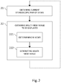
- Figure 2 is a flow chart for explaining a method for obtaining a multi-view image to be displayed on an auto-stereoscopic display according to an embodiment of the present disclosure.
- the auto-stereoscopic display is configured to display multi-view images comprising n views forming n-1 successive stereoscopic pairs of views (n being an integer strictly greater than two).
- Figure 3a, 3b and 3c illustrate the method presented in relation with figure 2 on a specific example.
- Multi-view image I1 comprises eight views (V15, V16, V17, V18, V19, V20, V21, V22) that form seven successive stereoscopic pairs of views of a same scene: (V15; V16), (V16; V17), (V17; V18), (V18; V19), (V19; V20), (V20; V21), (V21; V22). It is further assumed that the head of an observer O, watching the content displayed on the auto-stereoscopic display, has moved from position P1 to position P2. Figure 3a shows this initial situation.
- the current stereoscopic pair of views of I1 associated with the current location of an observer O is obtained.
- This current stereoscopic pair of views corresponds to the stereoscopic pair of views of I1 the observer actually sees, from his location in front of the auto-stereoscopic display. It can be easily determined, since characteristics of the auto-stereoscopic display are well known.
- the current stereoscopic pair of views associated with the location P2 of the observer is the pair (V16; V17).
- location of the observer it is meant in the present disclosure the location of the head of the observer. According to an embodiment, techniques such as eyes tracking may be employed to determine this location.
- step 22 the current stereoscopic pair of views is used to obtain a new multi-view image to be displayed on the auto-stereoscopic display.
- step 22 for obtaining a new multi-view image to be displayed on the auto-stereoscopic display comprises determining (221) n views responsive to the current stereoscopic pair of views, and generating (222) the multi-view image to be displayed from said n views previously determined.
- the n views are determined as a function of the current stereoscopic pair of views: these n views comprise the two views of the current stereoscopic pair of views, and the n-2 remaining views are selected so that they form, with the current stereoscopic pair of views, n-1 successive stereoscopic pairs of views in which the current stereoscopic pair of views occupies a substantially central position.
- the n-2 remaining views are selected so that the current stereoscopic pair of views occupies the exact central position in the n-1 successive stereoscopic pairs of views, which is position with rank n / 2.
- Figure 3b illustrates such an embodiment, with n being equal to eight.
- the current stereoscopic pair of views is (V16; V17).
- views V13, V14, V15, V18, V19 and V20 are then determined, so that these eight views forms seven successive stereoscopic pairs of views of the scene, the current stereoscopic pair of views (V16; V17) occupying the central position, which is the position with rank four, within the successive stereoscopic pairs of views: (V13; V14), (V14; V15), (V15; V16), (V16; V17) , (V17; V18), (V18; V19), (V19; V20).
- n views are determined so that the current stereoscopic pair of views occupies position with rank (n-1) / 2 or (n+1) / 2, which correspond to substantially central positions within the n-1 successive stereoscopic pairs of views.
- a direction of motion of the observer in front of the auto-stereoscopic display is also taken into account to determine the n views that will be used to generate a new multi-view image to be displayed on the auto-stereoscopic display.
- Such information regarding motion direction is useful, since it helps to estimate the direction (left or right) in which the observer is likely to move afterwards.
- P1 and P2 of the observer in front of the auto-stereoscopic display it can be determined that the observer has moved his head to his right to reach position P2.
- position P2 is obtained, there is a probability that the observer has not finished his motion and continues moving to his right afterwards.
- Figure 3c shows a result of such an embodiment (still assuming that situation of figure 3a is the initial situation).
- views V12, V13, V14, V15, V18 and V19 are now determined, so that these eight views forms seven successive stereoscopic pairs of views of the scene.
- the current stereoscopic pair of views (V16; V17) still occupies a substantially central position, but not the exact central position, within the set of successive stereoscopic pairs of views: (V12; V13), (V13; V14), (V14; V15), (V15; V16), (V16; V17), (V17; V18), (V18; V19).
- this offset of the current stereoscopic pair of views within the set of successive stereoscopic pairs of views offers more latitude, in term of coherent motion parallax effect, in the direction of a presumed future motion PFM of the observer.
- the knowledge of the previous direction of motion of the observer allows estimating the direction in which the observer is more likely to move afterwards, and can thus be used to determine the n views of a new multi-view image to be displayed on the auto-stereoscopic display accordingly, to maximize the chances of providing a coherent motion parallax effect.
- the number of views required to implement the proposed technique is greater than the number of views that can be displayed by an auto-stereoscopic display at the same time.
- thirty views V1 to V30 of a same scene may be available, each corresponding to a different point of view, while the auto-stereoscopic display can only handle eight views at the same time.
- the views used to generate a new multi-view image correspond either to views captured with some real capture devices, or to virtual views interpolated from the views captured by the capture devices.
- an image acquisition system comprising seven real cameras C1 to C7 is used to capture a scene Sc, thus providing, at a given time, seven different views of the scene Sc. From these seven views captured with real cameras, other views may be interpolated. For example, views that would have been obtained if some cameras had been placed at positions 3 or 4 represented in figure 4 may be interpolated. View interpolation, when needed, may be done at the image acquisition system level itself.
- determining the n views of a multi-view image to be displayed on the auto-stereoscopic display comprises interpolating at least one of said n views, from others views already available. Interpolating some views at a receiving device level (such as at the auto-stereoscopic display level) may for example be interesting to save some bandwidth on the link used to transmit data between a content provider and said receiving device.
- the n views previously determined are used to generate a multi-view image to be displayed on the auto-stereoscopic display, at step 222.
- the generation of the multi-view image to be displayed - in other words, the way the n views are multiplexed into a single multi-view image - takes account of the location of the observer in front of the auto-stereoscopic display.
- the multi-view image to be displayed may thus be generated so that the current stereoscopic pair of views is still associated with the predetermined location of the observer in front of said auto-stereoscopic display. This is for example illustrated in figure 3b , where a multi-view image I2 to be displayed is generated from views V13 to V20 determined at step 21.
- I2 is indeed generated so that current stereoscopic pair of views (V16; V17) is still associated to position P2 of the observer. In that way, if the observer hasn't moved again after having reached position P2, he will not notice any undesirable artefact when the image displayed on the auto-stereoscopic display changes from I1 to I2: he still sees the scene with the same point of view.
- the multi-view image is generated according to the location of the observer in front of the auto-stereoscopic display, so that the successive stereoscopic pairs of views are always substantially centred on the observer.
- the content displayed on the auto-stereoscopic display may thus be constantly adapted so that the observer is always substantially located at the centre of a zone in which motion parallax effect is respected.
- the multi-view image displayed on the auto-stereoscopic display is generated so that the observer is maintained, as far as possible, at a certain distance from transition zones, namely zones where the continuity of the motion parallax effect is broken, such as the one corresponding to the location of observer 03 in figure 1 .
- the motion parallax effect is respected since stereoscopic pairs of views that are adjacent to the current stereoscopic pair of views are already displayed on the auto-stereoscopic display (they belong to the same multi-view image, displayed on the auto-stereoscopic display).
- the proposed technique allows the multi-view image displayed on the auto-stereoscopic display to be refreshed before the observer reaches a transition zone.
- the observer can thus benefit from a continuous motion parallax effect all along the motion of his head.
- the implementation of the proposed technique has many advantages compared to prior art solutions: it offers time to refresh a multi-view image, allowing rendering a continuous horizontal motion parallax effect which is not limited to a narrow viewing zone, with unperceivable latency for the observer.
- the immersive experience is thus improved.
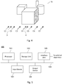
- Figure 5 is a schematic block diagram illustrating an example of a device for obtaining a multi-view image to be displayed on an auto-stereoscopic display according to an embodiment of the present disclosure.
- a device for obtaining a multi-view image to be displayed on an auto-stereoscopic display according to an embodiment of the present disclosure.
- such a device may be embedded in an auto-stereoscopic display. In another embodiment, it may be an external device connected to an auto-stereoscopic display.
- An apparatus 500 illustrated in figure 5 includes a processor 501, a storage unit 502, an input device 503, an output device 504, and an interface unit 505 which are connected by a bus 506.
- a processor 501 a storage unit 502
- an input device 503, an output device 504, and an interface unit 505 which are connected by a bus 506.
- constituent elements of the computer apparatus 500 may be connected by a connection other than a bus connection using the bus 506.
- the processor 501 controls operations of the apparatus 500.
- the storage unit 502 stores at least one program to be executed by the processor 501, and various data, including for example parameters used by computations performed by the processor 501, intermediate data of computations performed by the processor 501, and so on.
- the processor 501 is formed by any known and suitable hardware, or software, or a combination of hardware and software.
- the processor 501 is formed by dedicated hardware such as a processing circuit, or by a programmable processing unit such as a CPU (Central Processing Unit) that executes a program stored in a memory thereof.
- CPU Central Processing Unit
- the storage unit 502 is formed by any suitable storage or means capable of storing the program, data, or the like in a computer-readable manner. Examples of the storage unit 502 include non-transitory computer-readable storage media such as semiconductor memory devices, and magnetic, optical, or magneto-optical recording media loaded into a read and write unit.
- the program causes the processor 501 to perform a process for obtaining a multi-view image to be displayed on an auto-stereoscopic display according to an embodiment of the present disclosure as described previously. More particularly, the program causes the processor 501 to generate a multi-view image to be displayed on an auto-stereoscopic display. The views used to generate such multi-view image may be stored into storage unit 502.
- the input device 503 is formed for example by a device for determining the location of an observer in front of an auto-stereoscopic display.
- input device 503 is an eye-tracking device.
- the output device 504 is formed for example by an auto-stereoscopic display to display the multi-view image generated by applying the method for obtaining a multi-view image previously described.
- the interface unit 505 provides interfaces between the apparatus 500 and external apparatus.
- the interface unit 505 may be communicable with external apparatus via cable or wireless communication.
- an external apparatus may be such an auto-stereoscopic display.
- the device for determining the location of an observer may also be an external apparatus, if such a device is not embedded in the device for obtaining a multi-view image according to the proposed technique.
- processor 501 may comprise different modules and units embodying the functions carried out by apparatus 500 according to embodiments of the present disclosure, such as:
- modules and units may also be embodied in several processors 501 communicating and co-operating with each other.
Landscapes
- Engineering & Computer Science (AREA)
- Multimedia (AREA)
- Signal Processing (AREA)
- Physics & Mathematics (AREA)
- General Physics & Mathematics (AREA)
- Optics & Photonics (AREA)
- Testing, Inspecting, Measuring Of Stereoscopic Televisions And Televisions (AREA)
Priority Applications (2)
| Application Number | Priority Date | Filing Date | Title |
|---|---|---|---|
| EP16306433.0A EP3316575A1 (fr) | 2016-10-31 | 2016-10-31 | Procédé de fourniture d'un effet de parallaxe de mouvement continu au moyen d'un afficheur auto-stéréoscopique, dispositif correspondant, produit programme informatique et support lisible par ordinateur |
| US15/796,824 US20180124373A1 (en) | 2016-10-31 | 2017-10-29 | Method for providing continuous motion parallax effect using an auto-stereoscopic display, corresponding device, computer program product and computer-readable carrier medium |
Applications Claiming Priority (1)
| Application Number | Priority Date | Filing Date | Title |
|---|---|---|---|
| EP16306433.0A EP3316575A1 (fr) | 2016-10-31 | 2016-10-31 | Procédé de fourniture d'un effet de parallaxe de mouvement continu au moyen d'un afficheur auto-stéréoscopique, dispositif correspondant, produit programme informatique et support lisible par ordinateur |
Publications (1)
| Publication Number | Publication Date |
|---|---|
| EP3316575A1 true EP3316575A1 (fr) | 2018-05-02 |
Family
ID=57286423
Family Applications (1)
| Application Number | Title | Priority Date | Filing Date |
|---|---|---|---|
| EP16306433.0A Withdrawn EP3316575A1 (fr) | 2016-10-31 | 2016-10-31 | Procédé de fourniture d'un effet de parallaxe de mouvement continu au moyen d'un afficheur auto-stéréoscopique, dispositif correspondant, produit programme informatique et support lisible par ordinateur |
Country Status (2)
| Country | Link |
|---|---|
| US (1) | US20180124373A1 (fr) |
| EP (1) | EP3316575A1 (fr) |
Citations (3)
| Publication number | Priority date | Publication date | Assignee | Title |
|---|---|---|---|---|
| US20110242289A1 (en) * | 2010-03-31 | 2011-10-06 | Rieko Fukushima | Display apparatus and stereoscopic image display method |
| US20140071237A1 (en) * | 2011-06-15 | 2014-03-13 | Sony Corporation | Image processing device and method thereof, and program |
| US20140247329A1 (en) * | 2011-11-16 | 2014-09-04 | Kabushiki Kaisha Toshiba | Image processing device, stereoscopic image display apparatus, image processing method and image processing program |
Family Cites Families (3)
| Publication number | Priority date | Publication date | Assignee | Title |
|---|---|---|---|---|
| JP4324435B2 (ja) * | 2003-04-18 | 2009-09-02 | 三洋電機株式会社 | 立体視用映像提供方法及び立体映像表示装置 |
| CN102257818B (zh) * | 2008-10-17 | 2014-10-29 | 诺基亚公司 | 3d视频编码中运动向量的共享 |
| KR101615111B1 (ko) * | 2009-06-16 | 2016-04-25 | 삼성전자주식회사 | 다시점 영상 표시 장치 및 방법 |
-
2016
- 2016-10-31 EP EP16306433.0A patent/EP3316575A1/fr not_active Withdrawn
-
2017
- 2017-10-29 US US15/796,824 patent/US20180124373A1/en not_active Abandoned
Patent Citations (3)
| Publication number | Priority date | Publication date | Assignee | Title |
|---|---|---|---|---|
| US20110242289A1 (en) * | 2010-03-31 | 2011-10-06 | Rieko Fukushima | Display apparatus and stereoscopic image display method |
| US20140071237A1 (en) * | 2011-06-15 | 2014-03-13 | Sony Corporation | Image processing device and method thereof, and program |
| US20140247329A1 (en) * | 2011-11-16 | 2014-09-04 | Kabushiki Kaisha Toshiba | Image processing device, stereoscopic image display apparatus, image processing method and image processing program |
Also Published As
| Publication number | Publication date |
|---|---|
| US20180124373A1 (en) | 2018-05-03 |
Similar Documents
| Publication | Publication Date | Title |
|---|---|---|
| RU2568309C2 (ru) | Обнаружение формата трехмерного видео | |
| US8913790B2 (en) | System and method for analyzing three-dimensional (3D) media content | |
| US8488869B2 (en) | Image processing method and apparatus | |
| CN106060520B (zh) | 一种显示模式切换方法及其装置、智能终端 | |
| KR100517517B1 (ko) | 중간 시점 영상 합성 방법 및 그를 적용한 3d 디스플레이장치 | |
| US20140307062A1 (en) | System and method for generating a stereoscopic 3d presentation from picture sequence emanating from single lens source | |
| JPH0927969A (ja) | 複数画像の中間像生成方法及び視差推定方法および装置 | |
| US9154762B2 (en) | Stereoscopic image system utilizing pixel shifting and interpolation | |
| EP3340618A1 (fr) | Déformation géométrique d'un stéréogramme par contraintes de positions | |
| EP2509330A2 (fr) | Appareil et procédé de contrôle d'affichage et programme | |
| KR20150104458A (ko) | 3차원 영상을 디스플레이하는 방법 및 그 디스플레이 장치 | |
| US9972139B2 (en) | Image processing apparatus, image processing method and program | |
| CN103369331A (zh) | 图像空洞的填补方法和装置及视频图像的处理方法和装置 | |
| JP2010171628A (ja) | 画像処理装置、プログラム、画像処理方法、記録方法および記録媒体 | |
| WO2015115946A1 (fr) | Procédés d'encodage/décodage de contenu vidéo tridimensionnel | |
| US10354435B2 (en) | Tridimensional rendering with adjustable disparity direction | |
| EP3316575A1 (fr) | Procédé de fourniture d'un effet de parallaxe de mouvement continu au moyen d'un afficheur auto-stéréoscopique, dispositif correspondant, produit programme informatique et support lisible par ordinateur | |
| US9113140B2 (en) | Stereoscopic image processing device and method for generating interpolated frame with parallax and motion vector | |
| KR20200016363A (ko) | 2d 디스플레이 디바이스 상에, 광 필드 데이터로부터 유도되는 콘텐츠를 디스플레이하기 위한 방법 | |
| CN108197248B (zh) | 一种3d化2d网页显示的方法、装置及系统 | |
| KR20130139271A (ko) | 이미지 내의 그래픽 객체를 인크러스트하는 3차원 이미지들을 생성하는 방법 및 이와 관련된 디스플레이 디바이스 | |
| CN113867526A (zh) | 一种基于人眼追踪的优化显示方法、装置、设备及介质 | |
| Cho et al. | Prediction of visual discomfort in watching 3D video using multiple features | |
| CN102547349A (zh) | 快门式液晶立体显示器的3d图像处理装置及其方法 | |
| CN109508574A (zh) | 一种裸眼立体显示方法、装置及设备 |
Legal Events
| Date | Code | Title | Description |
|---|---|---|---|
| PUAI | Public reference made under article 153(3) epc to a published international application that has entered the european phase |
Free format text: ORIGINAL CODE: 0009012 |
|
| STAA | Information on the status of an ep patent application or granted ep patent |
Free format text: STATUS: THE APPLICATION HAS BEEN PUBLISHED |
|
| AK | Designated contracting states |
Kind code of ref document: A1 Designated state(s): AL AT BE BG CH CY CZ DE DK EE ES FI FR GB GR HR HU IE IS IT LI LT LU LV MC MK MT NL NO PL PT RO RS SE SI SK SM TR |
|
| AX | Request for extension of the european patent |
Extension state: BA ME |
|
| STAA | Information on the status of an ep patent application or granted ep patent |
Free format text: STATUS: REQUEST FOR EXAMINATION WAS MADE |
|
| 17P | Request for examination filed |
Effective date: 20181030 |
|
| RBV | Designated contracting states (corrected) |
Designated state(s): AL AT BE BG CH CY CZ DE DK EE ES FI FR GB GR HR HU IE IS IT LI LT LU LV MC MK MT NL NO PL PT RO RS SE SI SK SM TR |
|
| RIC1 | Information provided on ipc code assigned before grant |
Ipc: H04N 13/04 20060101ALI20170405BHEP Ipc: H04N 13/00 20180101AFI20170405BHEP Ipc: G02B 27/22 20180101ALI20170405BHEP |
|
| RAP1 | Party data changed (applicant data changed or rights of an application transferred) |
Owner name: INTERDIGITAL CE PATENT HOLDINGS |
|
| STAA | Information on the status of an ep patent application or granted ep patent |
Free format text: STATUS: EXAMINATION IS IN PROGRESS |
|
| 17Q | First examination report despatched |
Effective date: 20190514 |
|
| STAA | Information on the status of an ep patent application or granted ep patent |
Free format text: STATUS: THE APPLICATION IS DEEMED TO BE WITHDRAWN |
|
| 18D | Application deemed to be withdrawn |
Effective date: 20200603 |