EP3316479B1 - Power amplifier, power amplification method, and power amplification control device and method - Google Patents
Power amplifier, power amplification method, and power amplification control device and method Download PDFInfo
- Publication number
- EP3316479B1 EP3316479B1 EP15899210.7A EP15899210A EP3316479B1 EP 3316479 B1 EP3316479 B1 EP 3316479B1 EP 15899210 A EP15899210 A EP 15899210A EP 3316479 B1 EP3316479 B1 EP 3316479B1
- Authority
- EP
- European Patent Office
- Prior art keywords
- power
- input signals
- outphasing
- power amplifier
- doherty
- Prior art date
- Legal status (The legal status is an assumption and is not a legal conclusion. Google has not performed a legal analysis and makes no representation as to the accuracy of the status listed.)
- Active
Links
Images



Classifications
-
- H—ELECTRICITY
- H03—ELECTRONIC CIRCUITRY
- H03F—AMPLIFIERS
- H03F1/00—Details of amplifiers with only discharge tubes, only semiconductor devices or only unspecified devices as amplifying elements
- H03F1/02—Modifications of amplifiers to raise the efficiency, e.g. gliding Class A stages, use of an auxiliary oscillation
- H03F1/0205—Modifications of amplifiers to raise the efficiency, e.g. gliding Class A stages, use of an auxiliary oscillation in transistor amplifiers
- H03F1/0288—Modifications of amplifiers to raise the efficiency, e.g. gliding Class A stages, use of an auxiliary oscillation in transistor amplifiers using a main and one or several auxiliary peaking amplifiers whereby the load is connected to the main amplifier using an impedance inverter, e.g. Doherty amplifiers
-
- H—ELECTRICITY
- H03—ELECTRONIC CIRCUITRY
- H03F—AMPLIFIERS
- H03F1/00—Details of amplifiers with only discharge tubes, only semiconductor devices or only unspecified devices as amplifying elements
- H03F1/02—Modifications of amplifiers to raise the efficiency, e.g. gliding Class A stages, use of an auxiliary oscillation
- H03F1/0205—Modifications of amplifiers to raise the efficiency, e.g. gliding Class A stages, use of an auxiliary oscillation in transistor amplifiers
- H03F1/0294—Modifications of amplifiers to raise the efficiency, e.g. gliding Class A stages, use of an auxiliary oscillation in transistor amplifiers using vector summing of two or more constant amplitude phase-modulated signals
-
- H—ELECTRICITY
- H03—ELECTRONIC CIRCUITRY
- H03F—AMPLIFIERS
- H03F3/00—Amplifiers with only discharge tubes or only semiconductor devices as amplifying elements
- H03F3/189—High-frequency amplifiers, e.g. radio frequency amplifiers
- H03F3/19—High-frequency amplifiers, e.g. radio frequency amplifiers with semiconductor devices only
-
- H—ELECTRICITY
- H03—ELECTRONIC CIRCUITRY
- H03F—AMPLIFIERS
- H03F3/00—Amplifiers with only discharge tubes or only semiconductor devices as amplifying elements
- H03F3/20—Power amplifiers, e.g. Class B amplifiers, Class C amplifiers
- H03F3/21—Power amplifiers, e.g. Class B amplifiers, Class C amplifiers with semiconductor devices only
- H03F3/211—Power amplifiers, e.g. Class B amplifiers, Class C amplifiers with semiconductor devices only using a combination of several amplifiers
-
- H—ELECTRICITY
- H03—ELECTRONIC CIRCUITRY
- H03F—AMPLIFIERS
- H03F3/00—Amplifiers with only discharge tubes or only semiconductor devices as amplifying elements
- H03F3/20—Power amplifiers, e.g. Class B amplifiers, Class C amplifiers
- H03F3/24—Power amplifiers, e.g. Class B amplifiers, Class C amplifiers of transmitter output stages
- H03F3/245—Power amplifiers, e.g. Class B amplifiers, Class C amplifiers of transmitter output stages with semiconductor devices only
-
- H—ELECTRICITY
- H03—ELECTRONIC CIRCUITRY
- H03F—AMPLIFIERS
- H03F3/00—Amplifiers with only discharge tubes or only semiconductor devices as amplifying elements
- H03F3/60—Amplifiers in which coupling networks have distributed constants, e.g. with waveguide resonators
- H03F3/602—Combinations of several amplifiers
-
- H—ELECTRICITY
- H03—ELECTRONIC CIRCUITRY
- H03F—AMPLIFIERS
- H03F3/00—Amplifiers with only discharge tubes or only semiconductor devices as amplifying elements
- H03F3/62—Two-way amplifiers
-
- H—ELECTRICITY
- H03—ELECTRONIC CIRCUITRY
- H03F—AMPLIFIERS
- H03F2200/00—Indexing scheme relating to amplifiers
- H03F2200/405—Indexing scheme relating to amplifiers the output amplifying stage of an amplifier comprising more than three power stages
-
- H—ELECTRICITY
- H03—ELECTRONIC CIRCUITRY
- H03F—AMPLIFIERS
- H03F2200/00—Indexing scheme relating to amplifiers
- H03F2200/451—Indexing scheme relating to amplifiers the amplifier being a radio frequency amplifier
-
- H—ELECTRICITY
- H04—ELECTRIC COMMUNICATION TECHNIQUE
- H04W—WIRELESS COMMUNICATION NETWORKS
- H04W88/00—Devices specially adapted for wireless communication networks, e.g. terminals, base stations or access point devices
- H04W88/08—Access point devices
Definitions
- the present invention relates to the field of power amplifiers, and in particular, to a power amplification control apparatus with a signal control system and an amplifier with first and second working modes, and corresponding methods.
- a radio base station is configured to amplify an input signal by using a power amplifier (English: Power Amplifier, PA for short), and transmit the amplified input signal by using a transmitter.
- a power amplifier is a component consuming most power in a radio base station, and efficiency of the power amplifier directly affects power consumption of the entire radio base station.
- a Doherty (English: Doherty) power amplifier is usually used in an existing radio base station, to reduce power consumption of the radio base station.
- the Doherty power amplifier includes a primary power amplifier and at least one peak power amplifier.
- the primary power amplifier is connected in parallel to each peak power amplifier.
- a working principle of the Doherty power amplifier is that the primary power amplifier and each peak power amplifier can work in saturation regions thereof by using an active-load pulling technology, thereby ensuring that the entire Doherty power amplifier has relatively high efficiency within an input power range as large as possible.
- WO 2015/057118 A1 describes a power amplifier for amplification of an input signal into an output signal.
- WO 01/91282 A2 discloses an RF power amplifier and methods for improving the efficiency thereof.
- US 2014/266464 A1 discusses an apparatus and method for improving power efficiency in an outphasing amplifier with a non-isolating combiner.
- embodiments of the present invention provide power amplification control apparatusses, , and power amplification control methods.
- the invention is defined in the claims.
- a power amplifier having a structure including n Doherty power amplification units connected in parallel and an n-way outphasing combiner is used, and the power amplifier triggers, according to input powers of received signals, all or some of the Doherty power amplification units and the n-way outphasing combiner to be in a working state. Therefore, the problem that if a Doherty power amplifier having the existing architecture is used, to maintain high efficiency, a corresponding input power changing range is relatively small, and power consumption increases when the input power changing range is relatively large is resolved. High efficiency is maintained within a larger input power changing range by using the power amplifier having this structure, thereby further reducing power consumption.
- An outphasing power amplifier includes two power amplifiers connected in parallel and a two-way outphasing combiner.
- a working principle of the outphasing power amplifier is that the two power amplifiers separately amplify two received outphasing input signals, and the outphasing combiner combines the two amplified input signals, thereby improving efficiency of the power amplifier.
- a radio base station is a radio frequency signal transceiver, and is configured to provide a radio frequency signal for a mobile terminal within a signal coverage range of the radio base station.
- a radio base station 10 generally includes a control subsystem 11, a radio frequency subsystem 12, and an antenna subsystem 13.
- the control subsystem 11 processes, by using a building base band unit (English: Building Base band Unit, BBU for short) 111, the baseband signal that is not modulated, and sends the processed signal to the radio frequency subsystem 12 by means of a common public radio interface (English: Common Public Radio Interface, CPRI for short).
- a building base band unit English: Building Base band Unit, BBU for short
- CPRI Common Public Radio Interface
- the radio frequency subsystem 12 needs to amplify the received signal by using a power amplifier 121 inside the radio frequency subsystem 12. After amplifying the signal, the power amplifier 121 sends the amplified signal to the antenna subsystem 13.
- a GSM antenna and TMA control module (English: GSM Antenna and TMA control Module, GATM for short) 131 in the antenna subsystem 13 controls a tower mounted amplifier (English: Tower Mounted Amplifier, TMA for short) 132 to transmit the signal.
- the radio base station further includes another conventional subsystem
- the control subsystem, the radio frequency subsystem, and the antenna frequency subsystem further include other conventional components, and details are not described herein again.
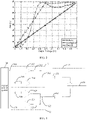
- FIG. 2 is an efficiency curve chart of a Doherty power amplifier, an outphasing power amplifier, and a conventional class-B power amplifier.
- a horizontal coordinate of the efficiency curve chart is an output voltage of a power amplifier after normalization, and a vertical coordinate of the efficiency curve chart is efficiency of the power amplifier.
- FIG. 3 is a schematic structural diagram of a power amplifier according to an embodiment which is corresponding to the claimed invention.
- the power amplifier includes two Doherty power amplification units connected in parallel and one two-way outphasing combiner.
- a first Doherty power amplification unit 31 and a second Doherty power amplification unit 32 are connected in parallel.
- the first Doherty power amplification unit 31 includes an input end 311 and an output end 312.
- the second Doherty power amplification unit 32 includes an input end 321 and an output end 322.
- the two-way outphasing combiner 33 includes two input ends and one output end, which are respectively a first input end 331, a second input end 332, and an output end 333.
- the two-way outphasing combiner may be a Chireix combiner or another combiner having an outphasing combination function.
- a type of the outphasing combiner is not limited in the present invention.
- the output end 312 of the first Doherty power amplification unit 31 is electrically connected to the first input end 331 of the two-way outphasing combiner 33.
- the output end 322 of the second Doherty power amplification unit 32 is electrically connected to the second input end 332 of the two-way outphasing combiner 33.
- the input end 311 of the first Doherty power amplification unit 31 and the input end 321 of the second Doherty power amplification unit 32 are both configured to receive an input signal sent by a signal control system 34.
- the output end 312 of the first Doherty power amplification unit 31 and the output end 322 of the second Doherty power amplification unit 32 are both configured to send an amplified input signal to the two-way outphasing combiner 33.
- the two-way outphasing combiner 33 amplifies signals received by means of the first input end 331 and the second input end 332, combines the signals, and then sends, by means of the output end 333, the signals after combination to a transmitter (which is not shown) for transmission.
- the first Doherty power amplification unit 31 and the second Doherty power amplification unit 32 each are a two-way Doherty power amplification unit. That is, the first Doherty power amplification unit 31 and the second Doherty power amplification unit 32 each include a primary power amplifier and a peak power amplifier.
- the primary power amplifier is biased at class B or class AB, and the peak power amplifier is biased at class C.
- the primary power amplifier keeps being in a working state, and the peak power amplifier starts to work only when an input power reaches an initial working power.
- the first Doherty power amplification unit 31 includes a primary power amplifier 313 and a peak power amplifier 314; and the second Doherty power amplification unit 32 includes a primary power amplifier 324 and a peak power amplifier 323.
- the primary power amplifier 313 and the peak power amplifier 314 are connected in parallel.
- the primary power amplifier 324 and the peak power amplifier 323 are connected in parallel.
- the primary power amplifier 313 and the peak power amplifier 314 need to be connected by using a Doherty combiner (which is not shown).
- the Doherty combiner is configured to combine signals that are amplified by the primary power amplifier 313 and the peak power amplifier 314.
- the primary power amplifier 324 and the peak power amplifier 323 need to be connected by using a Doherty combiner.
- a first microstrip 315 is connected in series at a rear end of the primary power amplifier 313, and a second microstrip 316 is connected in series at a front end of the peak power amplifier 314.
- the first microstrip 315 is used for impedance transformation, and the second microstrip 315 is used for phase balancing.
- the first microstrip 315 and the second microstrip 316 each may be a quarter-wave microstrip or an equivalent circuit.
- a third microstrip 325 is connected in series at a rear end of the primary power amplifier 324, and a fourth microstrip 326 is connected in series at a front end of the peak power amplifier 323.
- the third microstrip 325 has a same function as the first microstrip 315
- the fourth microstrip 326 has a same function as the second microstrip 316.
- the third microstrip 325 and the fourth microstrip 326 each may be a quarter-wave microstrip or an equivalent circuit.
- the first Doherty power amplification unit 31 is a two-way symmetric Doherty power amplification unit.
- the first Doherty power amplification unit 31 is a two-way asymmetric Doherty power amplification unit.
- the first Doherty power amplification unit 31 may be a two-way symmetric Doherty power amplification unit, or may be a two-way asymmetric Doherty power amplification unit.
- the second Doherty power amplification unit 32 may be a two-way symmetric Doherty power amplification unit, or may be a two-way asymmetric Doherty power amplification unit. This is not limited in the present invention.
- a structure of the Doherty power amplification unit is similar to that of a classical Doherty power amplifier
- a structure of the two-way outphasing combiner is similar to that of an outphasing combiner in a classical outphasing power amplifier.
- the Doherty power amplification unit and the two-way outphasing combiner further include other conventional elements, and details are not described again in this embodiment.
- each Doherty power amplification unit may be a two-way Doherty power amplification unit, and may be an m-way Doherty power amplification unit. That is, each Doherty power amplification unit includes one primary power amplifier and (m-1) peak power amplifiers, where m ⁇ 2 and m is an integer. The following makes descriptions by using another embodiment.
- FIG. 4 is a schematic structural diagram of a power amplifier according to another embodiment which is corresponding to the claimed invention.
- a Doherty power amplification unit in the power amplifier is a three-way Doherty power amplification unit is used as an example for description.
- the power amplifier includes:
- the output end 412 of the first Doherty power amplification unit 41 is electrically connected to the first input end 431 of the two-way outphasing combiner 43.
- the output end 422 of the second Doherty power amplification unit 42 is electrically connected to the second input end 432 of the two-way outphasing combiner 43.
- the input end 411 of the first Doherty power amplification unit 41 and the input end 421 of the second Doherty power amplification unit 42 are both configured to receive an input signal sent by a signal control system 44.
- the output end 412 of the first Doherty power amplification unit 41 and the output end 422 of the second Doherty power amplification unit 42 are both configured to send an amplified input signal to the two-way outphasing combiner 43.
- the two-way outphasing combiner 43 amplifies signals received by means of the first input end 431 and the second input end 432, combines the signals, and then sends, by means of the output end 433, the signals after combination to a transmitter (which is not shown) for transmission.
- the first Doherty power amplification unit 41 and the second Doherty power amplification unit 42 each are a three-way Doherty power amplification unit. That is, the first Doherty power amplification unit 31 and the second Doherty power amplification unit 32 each include a primary power amplifier and two peak power amplifiers.
- the primary power amplifier is biased at class B or class AB, and the peak power amplifiers are biased at class C.
- the primary power amplifier keeps being in a working state, and the peak power amplifiers start to work only when an input power reaches an initial working power corresponding to each peak power amplifier.
- the initial working powers corresponding to the peak power amplifiers may be the same or different. This is not limited in the present invention.
- the first Doherty power amplification unit 41 includes a primary power amplifier 413, a first peak power amplifier 414, and a second peak power amplifier 415; and the second Doherty power amplification unit 42 includes a primary power amplifier 423, a first peak power amplifier 424, and a second peak power amplifier 425.
- the primary power amplifier is connected in parallel to the peak power amplifiers, and the peak power amplifiers are connected in parallel.
- Transistors having a same power or different powers may be used in the primary power amplifier and the peak power amplifiers. This is not limited in the present invention.
- the three-way Doherty power amplification unit and the two-way outphasing combiner further include other conventional elements, and details are not described again in this embodiment.
- an outphasing combiner may include n input ends, where n ⁇ 2 and n is an integer. That is, the outphasing combiner may be an n-way outphasing combiner.
- a power amplifier includes n Doherty power amplification units, and output ends of the Doherty power amplification units are separately connected to input ends of the n-way outphasing combiner.
- the Doherty power amplification units may have a same quantity or different quantities of ways. That is, a total quantity of power amplifiers included in each Doherty power amplification unit may be the same or different.
- a power amplifier includes a first Doherty power amplification unit, a second Doherty power amplification unit, and a third Doherty power amplification unit.
- the first Doherty power amplification unit, the second Doherty power amplification unit, and the third Doherty power amplification unit each include a primary power amplifier and a peak power amplifier.
- a power amplifier includes a first Doherty power amplification unit, a second Doherty power amplification unit, and a third Doherty power amplification unit.
- the first Doherty power amplification unit includes a primary power amplifier and a peak power amplifier (that is, the first Doherty power amplification unit is a two-way Doherty unit).
- the second Doherty power amplification unit includes a primary power amplifier and two peak power amplifiers (that is, the second Doherty power amplification unit is a three-way Doherty unit).
- the third Doherty power amplification unit includes a primary power amplifier and three peak power amplifiers (that is, the third Doherty power amplification unit is a four-way Doherty unit).
- each power amplifier provided in the embodiments of the present invention needs to trigger, according to an input power of a received signal, all or some of Doherty power amplification units and an outphasing combiner to be in a working state, thereby improving efficiency of the power amplifier.
- FIG. 5 is a method flowchart of a power amplification method according to an embodiment which is not corresponding to the claimed invention.
- the power amplification method include the following steps:
- a power amplifier having a structure including n Doherty power amplification units connected in parallel and an n-way outphasing combiner is used, and the power amplifier triggers, according to input powers of received signals, all or some of the Doherty power amplification units and the n-way outphasing combiner to be in a working state. Therefore, the problem that if a Doherty power amplifier having the existing architecture is used, to maintain high efficiency, a corresponding input power changing range is relatively small, and power consumption increases when the input power changing range is relatively large is resolved. High efficiency is maintained within a larger input power changing range by using the power amplifier having this structure, thereby further reducing power consumption.
- a working mode of the power amplifier may be set to a first working mode or a second working mode according to an actual working need.
- the power amplifier first triggers a Doherty power amplification unit to be in a working state, and then triggers an n-way outphasing combiner to be in a working state.
- the power amplifier first triggers an n-way outphasing combiner to be in a working state, and then triggers a Doherty power amplification unit to be in a working state.
- FIG. 6A is a method flowchart of a power amplification method according to another embodiment which is not corresponding to the claimed invention.
- the power amplification method is applied to a power amplifier working in a first working mode is used as an example for description.
- the power amplification method includes the following steps.
- Step 601 Receive input signals by means of input ends of Doherty power amplification units.
- Each Doherty power amplification unit in the power amplifier receives, by means of an input end, an input signal sent by a signal control system.
- Step 602 When powers of the input signals received by the Doherty power amplification units are less than a first power threshold, and the input signals received by the Doherty power amplification units are non-outphasing, trigger a primary power amplifier and each peak power amplifier in each Doherty power amplification unit to be in a working state, and trigger an n-way outphasing combiner to be in a non-outphasing working state, where the first power threshold is greater than an initial working power of each peak power amplifier in each Doherty power amplification unit.
- a power threshold needs to be designed in advance for the power amplifier.
- the power threshold is used to trigger all or some of the Doherty power amplification units and the n-way outphasing combiner to be in a working state.
- the first power threshold corresponding to the power amplifier needs to be greater than an initial working power of each peak power amplifier in each Doherty power amplification unit, thereby ensuring that before a power of an input signal reaches the first power threshold, a primary power amplifier and each peak power amplifier in each Doherty power amplification unit are in a working state.
- the input signals sent by the signal control system to the Doherty power amplification units are non-outphasing input signals.
- the Doherty power amplification units amplify the non-outphasing input signals (which are still non-outphasing input signals).
- the n-way outphasing combiner is intended for combining n outphasing input signals, and when powers of input signals are less than the first power threshold, the signals received by the n-way outphasing combiner are non-outphasing input signals. Therefore, when powers of input signals are less than the first power threshold, the n-way outphasing combiner is in a non-outphasing working state.
- the non-outphasing working state is a working state in which the n-way outphasing combiner directly combines signals received by the input ends, and does not need to perform phase adjustment.
- Step 603 When the powers of the input signals received by the Doherty power amplification units are greater than the first power threshold, and the input signals received by the Doherty power amplification units are outphasing, trigger the primary power amplifier and each peak power amplifier in each Doherty power amplification unit to be in a working state, and trigger the n-way outphasing combiner to be in an outphasing working state.
- the primary power amplifier and each peak power amplifier in each Doherty power amplification unit are in a working state. As the powers of the input signals continuously increase, the primary power amplifier and each peak power amplifier are in a saturation status, and work with highest efficiency.
- the signal control system adjusts the input signals sent to the Doherty power amplification units to outphasing input signals, and the Doherty power amplification units amplify powers of the outphasing input signals (which are still outphasing input signals).
- the n-way outphasing combiner receives n outphasing signals
- the n-way outphasing combiner is triggered to be in an outphasing working state.
- the outphasing working state is a working state in which the n-way outphasing combiner performs phase adjustment on signals received by the input ends, and then combines the signals.
- a power amplifier working in the first working mode works in a Doherty mode, to improve efficiency under a low power condition; and when an input power is relatively high, the power amplifier works in an outphasing mode, to maintain high efficiency under a high power condition.
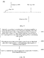
- FIG. 6B is an efficiency curve chart of a power amplifier in a first working mode according to an embodiment which is not corresponding to the claimed invention.
- the power amplifier works in a Doherty mode
- an efficiency curve of the power amplifier is an efficiency curve of a Doherty power amplifier.
- an efficiency curve of the power amplifier is an efficiency curve of an outphasing power amplifier.
- the power amplifier can maintain high efficiency within a larger input power range.
- a power amplifier having a structure including n Doherty power amplification units connected in parallel and an n-way outphasing combiner is used, and the power amplifier triggers, according to input powers of received signals, all or some of the Doherty power amplification units and the n-way outphasing combiner to be in a working state. Therefore, the problem that if a Doherty power amplifier having the existing architecture is used, to maintain high efficiency, a corresponding input power changing range is relatively small, and power consumption increases when the input power changing range is relatively large is resolved. High efficiency is maintained within a larger input power changing range by using the power amplifier having this structure, thereby further reducing power consumption.
- FIG. 7A is a method flowchart of a power amplification method according to still another embodiment which is not corresponding to the claimed invention.
- the power amplification method is applied to a power amplifier working in a second working mode is used as an example for description.
- the power amplification method includes the following steps.
- Step 701 Receive, by means of input ends of Doherty power amplification units, input signals sent by a signal control system.
- Each Doherty power amplification unit in the power amplifier receives an input signal by means of an input end.
- Step 702 When powers of the input signals received by the Doherty power amplification units are less than a second power threshold, and the input signals received by the Doherty power amplification units are outphasing, trigger a primary power amplifier in each Doherty power amplification unit to be in a working state, and trigger an n-way outphasing combiner to be in a non-outphasing working state, where the second power threshold is less than an initial working power of each peak power amplifier in each Doherty power amplification unit.
- a power threshold needs to be designed in advance for the power amplifier.
- the power threshold is used to trigger all or some of the Doherty power amplification units and the n-way outphasing combiner to be in a working state.
- the second power threshold corresponding to the power amplifier needs to be less than an initial working power of each peak power amplifier in each Doherty power amplification unit, thereby ensuring that before a power of an input signal reaches the first power threshold, no peak power amplifier in the Doherty power amplification units starts to work.
- signals sent by the signal control system to the Doherty power amplification units are outphasing input signals.
- No peak power amplifier in the Doherty power amplification units starts to work. Therefore, only the primary power amplifiers amplify the powers of the outphasing input signals (the amplified signals are still outphasing signals).
- the n-way outphasing combiner is intended for combining n outphasing signals. Therefore, when input ends of the n-way outphasing combiner receive n outphasing signals sent by the Doherty power amplification units, the n-way outphasing combiner is working in an outphasing working state.
- the outphasing working state is a working state in which the n-way outphasing combiner performs phase adjustment on signals received by the input ends, and then combines the signals.
- Step 703 When the powers of the input signals received by the Doherty power amplification units are greater than the second power threshold, and the input signals received by the Doherty power amplification units are non-outphasing, trigger the primary power amplifier and each peak power amplifier in each Doherty power amplification unit to be in a working state, and trigger the n-way outphasing combiner to be in a non-outphasing working state.
- the signal control system adjusts the input signals sent to the Doherty power amplification units to non-outphasing input signals, and the primary power amplifiers and peak power amplifiers in the Doherty power amplification units amplify powers of the non-outphasing input signals (the amplified signals are still non-outphasing signals).
- the n-way outphasing combiner is triggered to be in a non-outphasing working state.
- the non-outphasing working state is a working state in which the n-way outphasing combiner directly combines signals received by the input ends, and does not need to perform phase adjustment.
- FIG. 7B is an efficiency curve chart of a power amplifier in a second working mode according to an embodiment which is not corresponding to the claimed invention.
- the power amplifier works in an outphasing mode
- an efficiency curve of the power amplifier is an efficiency curve of an outphasing power amplifier.
- an efficiency curve of the power amplifier is an efficiency curve of a Doherty power amplifier.
- the power amplifier can maintain high efficiency within a larger input power range.
- a power amplifier having a structure including n Doherty power amplification units connected in parallel and an n-way outphasing combiner is used, and the power amplifier triggers, according to input powers of received signals, all or some of the Doherty power amplification units and the n-way outphasing combiner to be in a working state. Therefore, the problem that if a Doherty power amplifier having the existing architecture is used, to maintain high efficiency, a corresponding input power changing range is relatively small, and power consumption increases when the input power changing range is relatively large is resolved. High efficiency is maintained within a larger input power changing range by using the power amplifier having this structure, thereby further reducing power consumption.
- FIG. 8 is a structural block diagram of a power amplification control apparatus according to an embodiment corresponding to the claimed invention.
- the power amplification control apparatus is applied to a signal control system.
- the signal control system is used to provide an input signal for the power amplifier shown in FIG. 3 or FIG. 4 .
- the power amplification control apparatus includes:
- the power amplification control apparatus determines, according to a working mode of a power amplifier, a power threshold corresponding to the power amplifier, and adjusts input signals when powers of the input signals reach the power threshold, so that the input signals conform to the working mode of the power amplifier. Therefore, the problem that if a Doherty power amplifier having the existing architecture is used, to maintain high efficiency, a corresponding input power changing range is relatively small, and power consumption increases when the input power changing range is relatively large is resolved. High efficiency is maintained within a larger input power changing range by using the power amplifier having this structure, thereby further reducing power consumption.
- the working mode of the power amplifier is the first working mode, and the corresponding power threshold is a first power threshold, where the first power threshold is greater than an initial working power of each peak power amplifier in each Doherty power amplification unit;
- the working mode of the power amplifier is the second working mode
- the corresponding power threshold is a second power threshold, where the second power threshold is less than an initial working power of each peak power amplifier in each Doherty power amplification unit
- FIG. 9 is a block diagram of a power amplification control apparatus according to an embodiment which is not covered by the present invention.
- the power amplification control apparatus 900 may include: a bus 910, and a processor 920, a memory 930, and a transceiver 940 that are connected by using the bus 910.
- the memory 1030 is configured to store one or more instructions.
- the one or more instructions are configured to be performed by the processor 920.
- the processor 920 is configured to determine, according to a working mode of a power amplifier, a power threshold corresponding to the power amplifier, where the power threshold is used to instruct the signal control system to adjust, when powers of the n input signals reach the power threshold, the n input signals to n non-outphasing input signals or n outphasing input signals;
- the working mode of the power amplifier is the first working mode, and the corresponding power threshold is a first power threshold, where the first power threshold is greater than an initial working power of each peak power amplifier in each Doherty power amplification unit; and the processor 920 is further configured to adjust, when the powers of the n input signals reach the first power threshold, the n input signals to the n outphasing input signals.
- the processor 920 is further configured to adjust, when the powers of the n input signals do not reach the first power threshold, the n input signals to the n non-outphasing input signals.
- the working mode of the power amplifier is the second working mode
- the corresponding power threshold is a second power threshold, where the second power threshold is less than an initial working power of each peak power amplifier in each Doherty power amplification unit; and the processor 920 is further configured to adjust, when the powers of the n input signals reach the second power threshold, the n input signals to the n non-outphasing input signals.
- the processor 920 is further configured to adjust, when the powers of the n input signals do not reach the first power threshold, the n input signals to the n outphasing input signals.
- the power amplification control apparatus determines, according to a working mode of a power amplifier, a power threshold corresponding to the power amplifier, and adjusts input signals when powers of the input signals reach the power threshold, so that the input signals conform to the working mode of the power amplifier. Therefore, the problem that if a Doherty power amplifier having the existing architecture is used, to maintain high efficiency, a corresponding input power changing range is relatively small, and power consumption increases when the input power changing range is relatively large is resolved. High efficiency is maintained within a larger input power changing range by using the power amplifier having this structure, thereby further reducing power consumption.
- a signal control system providing input signals for the power amplifier needs to adjust the input signals in real time according to a power threshold corresponding to a working mode of the power amplifier.
- FIG. 10 is a flowchart of a power amplification control method according to an embodiment which is not covered by the present invention.
- the power amplification control method is applied to the signal control system in the foregoing embodiments is used as an example for description.
- the method includes the following steps.
- Step 1001 Determine, according to a working mode of a power amplifier, a power threshold corresponding to the power amplifier, where the power threshold is used to instruct the signal control system to adjust, when powers of n input signals reach the power threshold, the n input signals to n non-outphasing input signals or n outphasing input signals.
- the signal control system may further determine, according to powers of signals that need to be amplified and the working mode of the power amplifier, how to set n input signals when powers of the n input signals do not reach the power threshold.
- Step 1002 When the powers of the n input signals reach the power threshold, adjust the n input signals to n non-outphasing input signals or n outphasing input signals.
- the signal control system sets the n input signals in a signal setting manner corresponding to the n input signals that is determined in step 1001 when the powers of the n input signals do not reach the power threshold.
- Step 1003 Send the n adjusted input signals separately to input ends of Doherty power amplification units.
- a power threshold corresponding to a power amplifier is determined according to a working mode of the power amplifier, and input signals are adjusted when powers of the input signals reach the power threshold, so that the input signals conform to the working mode of the power amplifier.
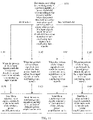
- FIG. 11 is a flowchart of a power amplification control method according to another embodiment which is corresponding to the claimed invention.
- the power amplification control method is applied to the signal control system shown in FIG. 3 or FIG. 4 is used as an example for description.
- the method includes the following steps.
- Step 1101 Determine, according to a working mode of a power amplifier, a power threshold corresponding to the power amplifier, where the power threshold is used to instruct the signal control system to adjust, when powers of n input signals reach the power threshold, the n input signals to n non-outphasing input signals or n outphasing input signals.
- the signal control system may store in advance power thresholds corresponding to a power amplifier in various working modes. When a skilled person selects a working mode of a to-be-connected power amplifier, the signal control system can obtain a power threshold corresponding to the working mode.
- the power amplifier provided in the embodiments of the present invention includes two working modes, and the two working modes correspond to different power thresholds. Therefore, when a working mode of the power amplifier connected to the signal control system is a first working mode, the signal control system determines that a power threshold corresponding to the power amplifier is a first power threshold; and when a working mode of the power amplifier connected to the signal control system is a second working mode, the signal control system determines that a power threshold corresponding to the power amplifier is a second power threshold.
- the first power threshold is greater than an initial working power of each peak power amplifier in each Doherty power amplification unit, thereby ensuring that when an input power reaches the first power threshold, each peak power amplifier in the Doherty power amplification unit is in a working state; and the second power threshold is less than an initial working power of each peak power amplifier in each Doherty power amplification unit, thereby ensuring that when an input power reaches the second power threshold, no peak power amplifier in the Doherty power amplification units starts to work.
- Step 1102 When the powers of the n input signals do not reach the first power threshold, adjust the n input signals to n non-outphasing input signals.
- the signal control system needs to adjust the n input signals to n non-outphasing input signals.
- the outphasing working state is a working state in which the n-way outphasing combiner directly combines signals received by input ends, and does not need to perform phase adjustment.
- Step 1103 Send the n non-outphasing input signals separately to input ends of Doherty power amplification units.
- the n-way outphasing combiner is intended for combining n outphasing signals. Therefore, when input ends of the n-way outphasing combiner receive n non-outphasing signals, the n-way outphasing combiner is in a non-outphasing working state, and combines the received non-outphasing signals.
- Step 1104 When the powers of the n input signals reach the first power threshold, adjust the n input signals to n outphasing input signals.
- the signal control system needs to adjust the n input signals to n outphasing input signals.
- step 1108 After performing the foregoing step 1104, the signal control system performs step 1108.
- Step 1105 When the powers of the n input signals do not reach the second power threshold, adjust the n input signals to n outphasing input signals.
- the signal control system needs to adjust the n input signals to n outphasing input signals, so as to trigger the n-way outphasing combiner to enter an outphasing working state.
- Step 1106 Send the n outphasing input signals separately to the input ends of the Doherty power amplification units.
- the n-way outphasing combiner when the input ends of the n-way outphasing combiner receive n outphasing input signals, the n-way outphasing combiner is triggered to enter an outphasing working state, and performs phase adjustment on the n received outphasing input signals, and then combines the signals.
- Step 1107 When the powers of the n input signals reach the second power threshold, adjust the n input signals to n non-outphasing input signals.
- the signal control system needs to adjust the n outphasing input signals to n non-outphasing input signals.
- step 1107 After performing the foregoing step 1107, the signal control system performs step 1108.
- Step 1108 Send the n adjusted input signals separately to the input ends of the Doherty power amplification units.
- the Doherty power amplification units receive the n adjusted input signals by means of the input ends of the Doherty power amplification units, amplify the input signals, and send the amplified signals to the n-way outphasing combiner for combination.
- the n outphasing input signals trigger the n-way outphasing combiner to enter an outphasing working state; and after the foregoing step 1107 is performed, the n non-outphasing input signals trigger the n-way outphasing combiner to enter a non-outphasing working state.
- a power threshold corresponding to a power amplifier is determined according to a working mode of the power amplifier, and input signals are adjusted when powers of the input signals reach the power threshold, so that the input signals conform to the working mode of the power amplifier. Therefore, the problem that if a Doherty power amplifier having the existing architecture is used, to maintain high efficiency, a corresponding input power changing range is relatively small, and power consumption increases when the input power changing range is relatively large is resolved. High efficiency is maintained within a larger input power changing range by using the power amplifier having this structure, thereby further reducing power consumption.
- the program may be stored in a computer-readable storage medium.
- the storage medium may include: a read-only memory, a magnetic disk, or an optical disc.
Landscapes
- Engineering & Computer Science (AREA)
- Power Engineering (AREA)
- Amplifiers (AREA)
Description
- The present invention relates to the field of power amplifiers, and in particular, to a power amplification control apparatus with a signal control system and an amplifier with first and second working modes, and corresponding methods.
- As a radio frequency signal transceiver, a radio base station is configured to amplify an input signal by using a power amplifier (English: Power Amplifier, PA for short), and transmit the amplified input signal by using a transmitter. A power amplifier is a component consuming most power in a radio base station, and efficiency of the power amplifier directly affects power consumption of the entire radio base station.
- A Doherty (English: Doherty) power amplifier is usually used in an existing radio base station, to reduce power consumption of the radio base station.
- The Doherty power amplifier includes a primary power amplifier and at least one peak power amplifier. The primary power amplifier is connected in parallel to each peak power amplifier. A working principle of the Doherty power amplifier is that the primary power amplifier and each peak power amplifier can work in saturation regions thereof by using an active-load pulling technology, thereby ensuring that the entire Doherty power amplifier has relatively high efficiency within an input power range as large as possible.
- In a process of implementing the present invention, it is found that the prior art has at least the following problem.
- If a Doherty power amplifier having the existing architecture is used, to maintain high efficiency, a corresponding input power changing range is relatively small, and power consumption increases when the input power changing range is relatively large. This cannot meet a requirement of a radio base station for power consumption.
-
WO 2015/057118 A1 describes a power amplifier for amplification of an input signal into an output signal. -
DE 10 2012 210249 A1 refers to an amplifier arrangement. -
WO 01/91282 A2 -
US 2014/266464 A1 discusses an apparatus and method for improving power efficiency in an outphasing amplifier with a non-isolating combiner. - To resolve a problem in the prior art that if a Doherty power amplifier having the existing architecture is used, to maintain high efficiency, a corresponding input power changing range is relatively small, and power consumption increases when the input power changing range is relatively large, embodiments of the present invention provide power amplification control apparatusses, , and power amplification control methods. The invention is defined in the claims.
- The technical solutions provided in the embodiments of the present invention have the following beneficial effects.
- A power amplifier having a structure including n Doherty power amplification units connected in parallel and an n-way outphasing combiner is used, and the power amplifier triggers, according to input powers of received signals, all or some of the Doherty power amplification units and the n-way outphasing combiner to be in a working state. Therefore, the problem that if a Doherty power amplifier having the existing architecture is used, to maintain high efficiency, a corresponding input power changing range is relatively small, and power consumption increases when the input power changing range is relatively large is resolved. High efficiency is maintained within a larger input power changing range by using the power amplifier having this structure, thereby further reducing power consumption.
- To describe the technical solutions in the embodiments of the present invention more clearly, the following briefly describes the accompanying drawings required for describing the embodiments. Apparently, the accompanying drawings in the following description show merely some embodiments of the present invention, and a person of ordinary skill in the art may still derive other drawings from these accompanying drawings without creative efforts.
-
FIG. 1 is a block diagram of a structure of a radio base station according to an embodiment which is not corresponding to the claimed invention; -
FIG. 2 is an efficiency curve chart of a Doherty power amplifier, an outphasing power amplifier, and a conventional class-B power amplifier; -
FIG. 3 is a schematic structural diagram of a power amplifier according to an embodiment which is corresponding to the claimed invention; -
FIG. 4 is a schematic structural diagram of a power amplifier according to another embodiment which is corresponding to the claimed invention; -
FIG. 5 is a method flowchart of a power amplification method according to an embodiment which is not corresponding to the claimed invention; -
FIG. 6A is a method flowchart of a power amplification method according to another embodiment which is not corresponding to the claimed invention; -
FIG. 6B is an efficiency curve chart of a power amplifier in a first working mode according to an embodiment which is not corresponding to the claimed invention; -
FIG. 7A is a method flowchart of a power amplification method according to still another embodiment which is not corresponding to the claimed invention; -
FIG. 7B is an efficiency curve chart of a power amplifier in a second working mode according to an embodiment which is not corresponding to the claimed invention; -
FIG. 8 is a structural block diagram of a power amplification control apparatus according to an embodiment which is corresponding to the claimed invention; -
FIG. 9 is a block diagram of a power amplification control apparatus according to an embodiment which is not corresponding to the claimed invention; -
FIG. 10 is a flowchart of a power amplification control method according to an embodiment which is not corresponding to the claimed invention; and -
FIG. 11 is a flowchart of a power amplification control method according to another embodiment which is corresponding to the claimed invention. - To make the objectives, technical solutions, and advantages of the present invention clearer, the following further describes the embodiments of the present invention in detail with reference to the accompanying drawings.
- For ease of understanding, first, some terminologies in embodiments of the present invention are explained.
- Outphasing power amplifier: An outphasing power amplifier includes two power amplifiers connected in parallel and a two-way outphasing combiner. A working principle of the outphasing power amplifier is that the two power amplifiers separately amplify two received outphasing input signals, and the outphasing combiner combines the two amplified input signals, thereby improving efficiency of the power amplifier.
- A radio base station is a radio frequency signal transceiver, and is configured to provide a radio frequency signal for a mobile terminal within a signal coverage range of the radio base station. As shown in
FIG. 1 , aradio base station 10 generally includes acontrol subsystem 11, aradio frequency subsystem 12, and anantenna subsystem 13. - Using that the
radio base station 10 transmits a radio frequency signal as an example, after receiving a baseband signal sent by theantenna subsystem 13, thecontrol subsystem 11 processes, by using a building base band unit (English: Building Base band Unit, BBU for short) 111, the baseband signal that is not modulated, and sends the processed signal to theradio frequency subsystem 12 by means of a common public radio interface (English: Common Public Radio Interface, CPRI for short). To ensure strength of the radio frequency signal received by amobile terminal 14, theradio frequency subsystem 12 needs to amplify the received signal by using apower amplifier 121 inside theradio frequency subsystem 12. After amplifying the signal, thepower amplifier 121 sends the amplified signal to theantenna subsystem 13. A GSM antenna and TMA control module (English: GSM Antenna and TMA control Module, GATM for short) 131 in theantenna subsystem 13 controls a tower mounted amplifier (English: Tower Mounted Amplifier, TMA for short) 132 to transmit the signal. - It should be noted that, a person skilled in the art may understand that, the radio base station further includes another conventional subsystem, and the control subsystem, the radio frequency subsystem, and the antenna frequency subsystem further include other conventional components, and details are not described herein again.
- Working efficiency of a power amplifier, which is a component consuming most power in a radio base station, directly affects power consumption of the entire radio base station. To reduce power consumption of a radio base station, in the prior art, a Doherty power amplifier, as a dominant high-efficiency power amplifier, is usually used in a radio base station.
-
FIG. 2 is an efficiency curve chart of a Doherty power amplifier, an outphasing power amplifier, and a conventional class-B power amplifier. A horizontal coordinate of the efficiency curve chart is an output voltage of a power amplifier after normalization, and a vertical coordinate of the efficiency curve chart is efficiency of the power amplifier. - An output voltage is in direct proportion to an input power. Apparently, compared with the conventional class-B power amplifier, the Doherty power amplifier and the outphasing power amplifier have apparently higher efficiency within a relatively large input power range. Referring to
FIG. 3, FIG. 3 is a schematic structural diagram of a power amplifier according to an embodiment which is corresponding to the claimed invention. The power amplifier includes two Doherty power amplification units connected in parallel and one two-way outphasing combiner. - A first Doherty
power amplification unit 31 and a second Dohertypower amplification unit 32 are connected in parallel. The first Dohertypower amplification unit 31 includes aninput end 311 and anoutput end 312. The second Dohertypower amplification unit 32 includes aninput end 321 and anoutput end 322. - The two-
way outphasing combiner 33 includes two input ends and one output end, which are respectively afirst input end 331, asecond input end 332, and anoutput end 333. The two-way outphasing combiner may be a Chireix combiner or another combiner having an outphasing combination function. A type of the outphasing combiner is not limited in the present invention. Theoutput end 312 of the first Dohertypower amplification unit 31 is electrically connected to thefirst input end 331 of the two-way outphasing combiner 33. Theoutput end 322 of the second Dohertypower amplification unit 32 is electrically connected to thesecond input end 332 of the two-way outphasing combiner 33. - The
input end 311 of the first Dohertypower amplification unit 31 and theinput end 321 of the second Dohertypower amplification unit 32 are both configured to receive an input signal sent by asignal control system 34. Theoutput end 312 of the first Dohertypower amplification unit 31 and theoutput end 322 of the second Dohertypower amplification unit 32 are both configured to send an amplified input signal to the two-way outphasing combiner 33. The two-way outphasing combiner 33 amplifies signals received by means of thefirst input end 331 and thesecond input end 332, combines the signals, and then sends, by means of theoutput end 333, the signals after combination to a transmitter (which is not shown) for transmission. - In
FIG. 3 , the first Dohertypower amplification unit 31 and the second Dohertypower amplification unit 32 each are a two-way Doherty power amplification unit. That is, the first Dohertypower amplification unit 31 and the second Dohertypower amplification unit 32 each include a primary power amplifier and a peak power amplifier. The primary power amplifier is biased at class B or class AB, and the peak power amplifier is biased at class C. In addition, the primary power amplifier keeps being in a working state, and the peak power amplifier starts to work only when an input power reaches an initial working power. - As shown in
FIG. 3 , the first Dohertypower amplification unit 31 includes aprimary power amplifier 313 and apeak power amplifier 314; and the second Dohertypower amplification unit 32 includes aprimary power amplifier 324 and apeak power amplifier 323. Theprimary power amplifier 313 and thepeak power amplifier 314 are connected in parallel. Theprimary power amplifier 324 and thepeak power amplifier 323 are connected in parallel. It should be noted that, theprimary power amplifier 313 and thepeak power amplifier 314 need to be connected by using a Doherty combiner (which is not shown). The Doherty combiner is configured to combine signals that are amplified by theprimary power amplifier 313 and thepeak power amplifier 314. Correspondingly, theprimary power amplifier 324 and thepeak power amplifier 323 need to be connected by using a Doherty combiner. - In the first Doherty
power amplification unit 31, afirst microstrip 315 is connected in series at a rear end of theprimary power amplifier 313, and asecond microstrip 316 is connected in series at a front end of thepeak power amplifier 314. Thefirst microstrip 315 is used for impedance transformation, and thesecond microstrip 315 is used for phase balancing. Thefirst microstrip 315 and thesecond microstrip 316 each may be a quarter-wave microstrip or an equivalent circuit. - Correspondingly, in the second Doherty
power amplification unit 32, athird microstrip 325 is connected in series at a rear end of theprimary power amplifier 324, and a fourth microstrip 326 is connected in series at a front end of thepeak power amplifier 323. In addition, thethird microstrip 325 has a same function as thefirst microstrip 315, and the fourth microstrip 326 has a same function as thesecond microstrip 316. Thethird microstrip 325 and the fourth microstrip 326 each may be a quarter-wave microstrip or an equivalent circuit. - When transistors having a same power are used in the
primary power amplifier 313 and thepeak power amplifier 314 in the first Dohertypower amplification unit 31, the first Dohertypower amplification unit 31 is a two-way symmetric Doherty power amplification unit. When transistors having different powers are used in theprimary power amplifier 313 and thepeak power amplifier 314 in the first Dohertypower amplification unit 31, the first Dohertypower amplification unit 31 is a two-way asymmetric Doherty power amplification unit. In this embodiment, the first Dohertypower amplification unit 31 may be a two-way symmetric Doherty power amplification unit, or may be a two-way asymmetric Doherty power amplification unit. Correspondingly, the second Dohertypower amplification unit 32 may be a two-way symmetric Doherty power amplification unit, or may be a two-way asymmetric Doherty power amplification unit. This is not limited in the present invention. - It should be noted that, in this embodiment, a structure of the Doherty power amplification unit is similar to that of a classical Doherty power amplifier, and a structure of the two-way outphasing combiner is similar to that of an outphasing combiner in a classical outphasing power amplifier. A person skilled in the art may understand that, in this embodiment, the Doherty power amplification unit and the two-way outphasing combiner further include other conventional elements, and details are not described again in this embodiment.
- In an optional embodiment, each Doherty power amplification unit may be a two-way Doherty power amplification unit, and may be an m-way Doherty power amplification unit. That is, each Doherty power amplification unit includes one primary power amplifier and (m-1) peak power amplifiers, where m≥2 and m is an integer. The following makes descriptions by using another embodiment.
- Referring to
FIG. 4, FIG. 4 is a schematic structural diagram of a power amplifier according to another embodiment which is corresponding to the claimed invention. In this embodiment, that a Doherty power amplification unit in the power amplifier is a three-way Doherty power amplification unit is used as an example for description. The power amplifier includes: - a first Doherty
power amplification unit 41 and a second Dohertypower amplification unit 42 that are connected in parallel, where the first Dohertypower amplification unit 41 includes aninput end 411 and anoutput end 412, and the second Dohertypower amplification unit 42 includes aninput end 421 and anoutput end 422; and - a two-
way outphasing combiner 43 including two input ends and one output end, which are respectively afirst input end 431, asecond input end 432, and anoutput end 433. The two-way outphasing combiner may be a Chireix combiner or another combiner having an outphasing function. A type of the outphasing combiner is not limited in the present invention. - The
output end 412 of the first Dohertypower amplification unit 41 is electrically connected to thefirst input end 431 of the two-way outphasing combiner 43. Theoutput end 422 of the second Dohertypower amplification unit 42 is electrically connected to thesecond input end 432 of the two-way outphasing combiner 43. - The
input end 411 of the first Dohertypower amplification unit 41 and theinput end 421 of the second Dohertypower amplification unit 42 are both configured to receive an input signal sent by asignal control system 44. Theoutput end 412 of the first Dohertypower amplification unit 41 and theoutput end 422 of the second Dohertypower amplification unit 42 are both configured to send an amplified input signal to the two-way outphasing combiner 43. The two-way outphasing combiner 43 amplifies signals received by means of thefirst input end 431 and thesecond input end 432, combines the signals, and then sends, by means of theoutput end 433, the signals after combination to a transmitter (which is not shown) for transmission. - In
FIG. 4 , the first Dohertypower amplification unit 41 and the second Dohertypower amplification unit 42 each are a three-way Doherty power amplification unit. That is, the first Dohertypower amplification unit 31 and the second Dohertypower amplification unit 32 each include a primary power amplifier and two peak power amplifiers. - The primary power amplifier is biased at class B or class AB, and the peak power amplifiers are biased at class C. In addition, the primary power amplifier keeps being in a working state, and the peak power amplifiers start to work only when an input power reaches an initial working power corresponding to each peak power amplifier. In addition, the initial working powers corresponding to the peak power amplifiers may be the same or different. This is not limited in the present invention.
- As shown in
FIG. 4 , the first Dohertypower amplification unit 41 includes aprimary power amplifier 413, a firstpeak power amplifier 414, and a secondpeak power amplifier 415; and the second Dohertypower amplification unit 42 includes aprimary power amplifier 423, a firstpeak power amplifier 424, and a secondpeak power amplifier 425. The primary power amplifier is connected in parallel to the peak power amplifiers, and the peak power amplifiers are connected in parallel. Transistors having a same power or different powers may be used in the primary power amplifier and the peak power amplifiers. This is not limited in the present invention. - It should be noted that, a person skilled in the art may understand that, in this embodiment, the three-way Doherty power amplification unit and the two-way outphasing combiner further include other conventional elements, and details are not described again in this embodiment.
- In this embodiment of the present invention, an outphasing combiner may include n input ends, where n≥2 and n is an integer. That is, the outphasing combiner may be an n-way outphasing combiner. Correspondingly, a power amplifier includes n Doherty power amplification units, and output ends of the Doherty power amplification units are separately connected to input ends of the n-way outphasing combiner.
- In addition, the Doherty power amplification units may have a same quantity or different quantities of ways. That is, a total quantity of power amplifiers included in each Doherty power amplification unit may be the same or different.
- For example, a power amplifier includes a first Doherty power amplification unit, a second Doherty power amplification unit, and a third Doherty power amplification unit. The first Doherty power amplification unit, the second Doherty power amplification unit, and the third Doherty power amplification unit each include a primary power amplifier and a peak power amplifier.
- For another example, a power amplifier includes a first Doherty power amplification unit, a second Doherty power amplification unit, and a third Doherty power amplification unit. The first Doherty power amplification unit includes a primary power amplifier and a peak power amplifier (that is, the first Doherty power amplification unit is a two-way Doherty unit). The second Doherty power amplification unit includes a primary power amplifier and two peak power amplifiers (that is, the second Doherty power amplification unit is a three-way Doherty unit). The third Doherty power amplification unit includes a primary power amplifier and three peak power amplifiers (that is, the third Doherty power amplification unit is a four-way Doherty unit). When working, each power amplifier provided in the embodiments of the present invention needs to trigger, according to an input power of a received signal, all or some of Doherty power amplification units and an outphasing combiner to be in a working state, thereby improving efficiency of the power amplifier.
- Referring to
FIG. 5, FIG. 5 is a method flowchart of a power amplification method according to an embodiment which is not corresponding to the claimed invention. In this embodiment, that the power amplification method is applied to the power amplifiers shown in the foregoing embodiments. The power amplification method include the following steps: - Step 501: Receive input signals by means of input ends of Doherty power amplification units.
- Step 502: Trigger, according to powers of the input signals, all or some of Doherty power amplification units and an n-way outphasing combiner to be in a working state.
- To sum up, in the power amplification method provided in this embodiment, a power amplifier having a structure including n Doherty power amplification units connected in parallel and an n-way outphasing combiner is used, and the power amplifier triggers, according to input powers of received signals, all or some of the Doherty power amplification units and the n-way outphasing combiner to be in a working state. Therefore, the problem that if a Doherty power amplifier having the existing architecture is used, to maintain high efficiency, a corresponding input power changing range is relatively small, and power consumption increases when the input power changing range is relatively large is resolved. High efficiency is maintained within a larger input power changing range by using the power amplifier having this structure, thereby further reducing power consumption.
- During design of a power amplifier, a working mode of the power amplifier may be set to a first working mode or a second working mode according to an actual working need. In the first working mode, the power amplifier first triggers a Doherty power amplification unit to be in a working state, and then triggers an n-way outphasing combiner to be in a working state. In the second working mode, the power amplifier first triggers an n-way outphasing combiner to be in a working state, and then triggers a Doherty power amplification unit to be in a working state. The following makes descriptions by using two embodiments.
- Referring to
FIG. 6A, FIG. 6A is a method flowchart of a power amplification method according to another embodiment which is not corresponding to the claimed invention. In this embodiment, that the power amplification method is applied to a power amplifier working in a first working mode is used as an example for description. The power amplification method includes the following steps. - Step 601: Receive input signals by means of input ends of Doherty power amplification units. Each Doherty power amplification unit in the power amplifier receives, by means of an input end, an input signal sent by a signal control system.
- Step 602: When powers of the input signals received by the Doherty power amplification units are less than a first power threshold, and the input signals received by the Doherty power amplification units are non-outphasing, trigger a primary power amplifier and each peak power amplifier in each Doherty power amplification unit to be in a working state, and trigger an n-way outphasing combiner to be in a non-outphasing working state, where the first power threshold is greater than an initial working power of each peak power amplifier in each Doherty power amplification unit.
- During design of a power amplifier, a power threshold needs to be designed in advance for the power amplifier. The power threshold is used to trigger all or some of the Doherty power amplification units and the n-way outphasing combiner to be in a working state.
- For the power amplifier that is set to working in the first working mode, the first power threshold corresponding to the power amplifier needs to be greater than an initial working power of each peak power amplifier in each Doherty power amplification unit, thereby ensuring that before a power of an input signal reaches the first power threshold, a primary power amplifier and each peak power amplifier in each Doherty power amplification unit are in a working state.
- In addition, when the powers of the input signals are less than the first power threshold, the input signals sent by the signal control system to the Doherty power amplification units are non-outphasing input signals. The Doherty power amplification units amplify the non-outphasing input signals (which are still non-outphasing input signals). The n-way outphasing combiner is intended for combining n outphasing input signals, and when powers of input signals are less than the first power threshold, the signals received by the n-way outphasing combiner are non-outphasing input signals. Therefore, when powers of input signals are less than the first power threshold, the n-way outphasing combiner is in a non-outphasing working state. The non-outphasing working state is a working state in which the n-way outphasing combiner directly combines signals received by the input ends, and does not need to perform phase adjustment.
- Step 603: When the powers of the input signals received by the Doherty power amplification units are greater than the first power threshold, and the input signals received by the Doherty power amplification units are outphasing, trigger the primary power amplifier and each peak power amplifier in each Doherty power amplification unit to be in a working state, and trigger the n-way outphasing combiner to be in an outphasing working state.
- When the powers of the input signals received by the Doherty power amplification units are greater than the first power threshold, the primary power amplifier and each peak power amplifier in each Doherty power amplification unit are in a working state. As the powers of the input signals continuously increase, the primary power amplifier and each peak power amplifier are in a saturation status, and work with highest efficiency.
- In addition, when the powers of the input signals are greater than the first power threshold, the signal control system adjusts the input signals sent to the Doherty power amplification units to outphasing input signals, and the Doherty power amplification units amplify powers of the outphasing input signals (which are still outphasing input signals). In this case, when the input ends of the n-way outphasing combiner receive n outphasing signals, the n-way outphasing combiner is triggered to be in an outphasing working state. The outphasing working state is a working state in which the n-way outphasing combiner performs phase adjustment on signals received by the input ends, and then combines the signals.
- Briefly, when an input power is relatively low, a power amplifier working in the first working mode works in a Doherty mode, to improve efficiency under a low power condition; and when an input power is relatively high, the power amplifier works in an outphasing mode, to maintain high efficiency under a high power condition.
-
FIG. 6B is an efficiency curve chart of a power amplifier in a first working mode according to an embodiment which is not corresponding to the claimed invention. Apparently, in the first working mode, when an input power is relatively low, the power amplifier works in a Doherty mode, and an efficiency curve of the power amplifier is an efficiency curve of a Doherty power amplifier. When an input power is relatively high, the power amplifier works in an outphasing mode, and an efficiency curve of the power amplifier is an efficiency curve of an outphasing power amplifier. Compared with a conventional Doherty power amplifier, the power amplifier can maintain high efficiency within a larger input power range. - To sum up, in the power amplification method provided in this embodiment, a power amplifier having a structure including n Doherty power amplification units connected in parallel and an n-way outphasing combiner is used, and the power amplifier triggers, according to input powers of received signals, all or some of the Doherty power amplification units and the n-way outphasing combiner to be in a working state. Therefore, the problem that if a Doherty power amplifier having the existing architecture is used, to maintain high efficiency, a corresponding input power changing range is relatively small, and power consumption increases when the input power changing range is relatively large is resolved. High efficiency is maintained within a larger input power changing range by using the power amplifier having this structure, thereby further reducing power consumption.
- Referring to
FIG. 7A, FIG. 7A is a method flowchart of a power amplification method according to still another embodiment which is not corresponding to the claimed invention. In this embodiment, that the power amplification method is applied to a power amplifier working in a second working mode is used as an example for description. The power amplification method includes the following steps. - Step 701: Receive, by means of input ends of Doherty power amplification units, input signals sent by a signal control system.
- Each Doherty power amplification unit in the power amplifier receives an input signal by means of an input end.
- Step 702: When powers of the input signals received by the Doherty power amplification units are less than a second power threshold, and the input signals received by the Doherty power amplification units are outphasing, trigger a primary power amplifier in each Doherty power amplification unit to be in a working state, and trigger an n-way outphasing combiner to be in a non-outphasing working state, where the second power threshold is less than an initial working power of each peak power amplifier in each Doherty power amplification unit.
- During design of a power amplifier, a power threshold needs to be designed in advance for the power amplifier. The power threshold is used to trigger all or some of the Doherty power amplification units and the n-way outphasing combiner to be in a working state.
- For the power amplifier that is set to working in the first working mode, the second power threshold corresponding to the power amplifier needs to be less than an initial working power of each peak power amplifier in each Doherty power amplification unit, thereby ensuring that before a power of an input signal reaches the first power threshold, no peak power amplifier in the Doherty power amplification units starts to work.
- In addition, when the powers of the input signals are less than the second power threshold, signals sent by the signal control system to the Doherty power amplification units are outphasing input signals. No peak power amplifier in the Doherty power amplification units starts to work. Therefore, only the primary power amplifiers amplify the powers of the outphasing input signals (the amplified signals are still outphasing signals). The n-way outphasing combiner is intended for combining n outphasing signals. Therefore, when input ends of the n-way outphasing combiner receive n outphasing signals sent by the Doherty power amplification units, the n-way outphasing combiner is working in an outphasing working state. The outphasing working state is a working state in which the n-way outphasing combiner performs phase adjustment on signals received by the input ends, and then combines the signals.
- Step 703: When the powers of the input signals received by the Doherty power amplification units are greater than the second power threshold, and the input signals received by the Doherty power amplification units are non-outphasing, trigger the primary power amplifier and each peak power amplifier in each Doherty power amplification unit to be in a working state, and trigger the n-way outphasing combiner to be in a non-outphasing working state.
- When the powers of the input signals received by the Doherty power amplification units are greater than the second power threshold, as the powers of the input signals increase, peak power amplifiers in the Doherty power amplification units successively enter a working state.
- In addition, when the powers of the input signals are greater than the second power threshold, the signal control system adjusts the input signals sent to the Doherty power amplification units to non-outphasing input signals, and the primary power amplifiers and peak power amplifiers in the Doherty power amplification units amplify powers of the non-outphasing input signals (the amplified signals are still non-outphasing signals). In this case, because signals received by the input ends of the n-way outphasing combiner are n non-outphasing signals, the n-way outphasing combiner is triggered to be in a non-outphasing working state. The non-outphasing working state is a working state in which the n-way outphasing combiner directly combines signals received by the input ends, and does not need to perform phase adjustment.
-
FIG. 7B is an efficiency curve chart of a power amplifier in a second working mode according to an embodiment which is not corresponding to the claimed invention. Apparently, in the second working mode, when an input power is relatively low, the power amplifier works in an outphasing mode, and an efficiency curve of the power amplifier is an efficiency curve of an outphasing power amplifier. When an input power is relatively high, the power amplifier works in a Doherty mode, and an efficiency curve of the power amplifier is an efficiency curve of a Doherty power amplifier. Compared with a conventional Doherty power amplifier, the power amplifier can maintain high efficiency within a larger input power range. - To sum up, in the power amplification method provided in this embodiment, a power amplifier having a structure including n Doherty power amplification units connected in parallel and an n-way outphasing combiner is used, and the power amplifier triggers, according to input powers of received signals, all or some of the Doherty power amplification units and the n-way outphasing combiner to be in a working state. Therefore, the problem that if a Doherty power amplifier having the existing architecture is used, to maintain high efficiency, a corresponding input power changing range is relatively small, and power consumption increases when the input power changing range is relatively large is resolved. High efficiency is maintained within a larger input power changing range by using the power amplifier having this structure, thereby further reducing power consumption.
- Referring to
FIG. 8, FIG. 8 is a structural block diagram of a power amplification control apparatus according to an embodiment corresponding to the claimed invention. The power amplification control apparatus is applied to a signal control system. The signal control system is used to provide an input signal for the power amplifier shown inFIG. 3 orFIG. 4 . The power amplification control apparatus includes: - a
processing module 810, configured to determine, according to a working mode of the power amplifier, a power threshold corresponding to the power amplifier, where the power threshold is used to instruct the signal control system to adjust, when powers of the n input signals reach the power threshold, the n input signals to n non-outphasing input signals or n outphasing input signals, where - the
processing module 810 is further configured to adjust, when the powers of the n input signals reach the power threshold, the n input signals to the n non-outphasing input signals or the n outphasing input signals; and - a sending
module 820, configured to send the n adjusted input signals separately to input ends of the Doherty power amplification units. - To sum up, the power amplification control apparatus provided in this embodiment determines, according to a working mode of a power amplifier, a power threshold corresponding to the power amplifier, and adjusts input signals when powers of the input signals reach the power threshold, so that the input signals conform to the working mode of the power amplifier. Therefore, the problem that if a Doherty power amplifier having the existing architecture is used, to maintain high efficiency, a corresponding input power changing range is relatively small, and power consumption increases when the input power changing range is relatively large is resolved. High efficiency is maintained within a larger input power changing range by using the power amplifier having this structure, thereby further reducing power consumption.
- Based on
FIG. 8 , the working mode of the power amplifier is the first working mode, and the corresponding power threshold is a first power threshold, where the first power threshold is greater than an initial working power of each peak power amplifier in each Doherty power amplification unit; and - the
processing module 810 is further configured to adjust, when the powers of the n input signals reach the first power threshold, the n input signals to the n outphasing input signals, and - the
processing module 810 is further configured to adjust, when the powers of the n input signals do not reach the first power threshold, the n input signals to the n non-outphasing input signals. - According to another embodiment which is covered by the claimed invention, based on
Fig.8 , the working mode of the power amplifier is the second working mode, and the corresponding power threshold is a second power threshold, where the second power threshold is less than an initial working power of each peak power amplifier in each Doherty power amplification unit; and - the
processing module 810 is further configured to adjust, when the powers of the n input signals reach the second power threshold, the n input signals to the n non-outphasing input signals, and - the
processing module 810 is configured to adjust, when the powers of the n input signals do not reach the second power threshold, the n input signals to the n outphasing input signals. - Referring to
FIG. 9, FIG. 9 is a block diagram of a power amplification control apparatus according to an embodiment which is not covered by the present invention. The poweramplification control apparatus 900 may include: a bus 910, and aprocessor 920, amemory 930, and atransceiver 940 that are connected by using the bus 910. The memory 1030 is configured to store one or more instructions. The one or more instructions are configured to be performed by theprocessor 920. - The
processor 920 is configured to determine, according to a working mode of a power amplifier, a power threshold corresponding to the power amplifier, where the power threshold is used to instruct the signal control system to adjust, when powers of the n input signals reach the power threshold, the n input signals to n non-outphasing input signals or n outphasing input signals; - the
processor 920 is further configured to adjust, when the powers of the n input signals reach the power threshold, the n input signals to the n non-outphasing input signals or the n outphasing input signals; and - the
processor 920 is further configured to control thetransceiver 940 to send the n adjusted input signals separately to input ends of the Doherty power amplification units. - Optionally, the working mode of the power amplifier is the first working mode, and the corresponding power threshold is a first power threshold, where the first power threshold is greater than an initial working power of each peak power amplifier in each Doherty power amplification unit; and
theprocessor 920 is further configured to adjust, when the powers of the n input signals reach the first power threshold, the n input signals to the n outphasing input signals. Optionally, theprocessor 920 is further configured to adjust, when the powers of the n input signals do not reach the first power threshold, the n input signals to the n non-outphasing input signals. - Optionally, the working mode of the power amplifier is the second working mode, and the corresponding power threshold is a second power threshold, where the second power threshold is less than an initial working power of each peak power amplifier in each Doherty power amplification unit; and
theprocessor 920 is further configured to adjust, when the powers of the n input signals reach the second power threshold, the n input signals to the n non-outphasing input signals. - Optionally, the
processor 920 is further configured to adjust, when the powers of the n input signals do not reach the first power threshold, the n input signals to the n outphasing input signals. - To sum up, the power amplification control apparatus provided in this embodiment determines, according to a working mode of a power amplifier, a power threshold corresponding to the power amplifier, and adjusts input signals when powers of the input signals reach the power threshold, so that the input signals conform to the working mode of the power amplifier. Therefore, the problem that if a Doherty power amplifier having the existing architecture is used, to maintain high efficiency, a corresponding input power changing range is relatively small, and power consumption increases when the input power changing range is relatively large is resolved. High efficiency is maintained within a larger input power changing range by using the power amplifier having this structure, thereby further reducing power consumption.
- To ensure high working efficiency of the power amplifier, a signal control system providing input signals for the power amplifier needs to adjust the input signals in real time according to a power threshold corresponding to a working mode of the power amplifier. The following makes descriptions by using an embodiment.
- Referring to
FIG. 10, FIG. 10 is a flowchart of a power amplification control method according to an embodiment which is not covered by the present invention. In this embodiment, that the power amplification control method is applied to the signal control system in the foregoing embodiments is used as an example for description. The method includes the following steps. - Step 1001: Determine, according to a working mode of a power amplifier, a power threshold corresponding to the power amplifier, where the power threshold is used to instruct the signal control system to adjust, when powers of n input signals reach the power threshold, the n input signals to n non-outphasing input signals or n outphasing input signals.
- The signal control system may further determine, according to powers of signals that need to be amplified and the working mode of the power amplifier, how to set n input signals when powers of the n input signals do not reach the power threshold.
- Step 1002: When the powers of the n input signals reach the power threshold, adjust the n input signals to n non-outphasing input signals or n outphasing input signals.
- When the powers of the n input signals do not reach the power threshold, the signal control system sets the n input signals in a signal setting manner corresponding to the n input signals that is determined in
step 1001 when the powers of the n input signals do not reach the power threshold. - Step 1003: Send the n adjusted input signals separately to input ends of Doherty power amplification units.
- To sum up, in the power amplification control method provided in this embodiment, a power threshold corresponding to a power amplifier is determined according to a working mode of the power amplifier, and input signals are adjusted when powers of the input signals reach the power threshold, so that the input signals conform to the working mode of the power amplifier.
- Therefore, the problem that if a Doherty power amplifier having the existing architecture is used, to maintain high efficiency, a corresponding input power changing range is relatively small, and power consumption increases when the input power changing range is relatively large is resolved. High efficiency is maintained within a larger input power changing range by using the power amplifier having this structure, thereby further reducing power consumption.
- Referring to
FIG. 11, FIG. 11 is a flowchart of a power amplification control method according to another embodiment which is corresponding to the claimed invention. In this embodiment, that the power amplification control method is applied to the signal control system shown inFIG. 3 orFIG. 4 is used as an example for description. The method includes the following steps. - Step 1101: Determine, according to a working mode of a power amplifier, a power threshold corresponding to the power amplifier, where the power threshold is used to instruct the signal control system to adjust, when powers of n input signals reach the power threshold, the n input signals to n non-outphasing input signals or n outphasing input signals.
- The signal control system may store in advance power thresholds corresponding to a power amplifier in various working modes. When a skilled person selects a working mode of a to-be-connected power amplifier, the signal control system can obtain a power threshold corresponding to the working mode.
- The power amplifier provided in the embodiments of the present invention includes two working modes, and the two working modes correspond to different power thresholds. Therefore, when a working mode of the power amplifier connected to the signal control system is a first working mode, the signal control system determines that a power threshold corresponding to the power amplifier is a first power threshold; and when a working mode of the power amplifier connected to the signal control system is a second working mode, the signal control system determines that a power threshold corresponding to the power amplifier is a second power threshold.
- The first power threshold is greater than an initial working power of each peak power amplifier in each Doherty power amplification unit, thereby ensuring that when an input power reaches the first power threshold, each peak power amplifier in the Doherty power amplification unit is in a working state; and the second power threshold is less than an initial working power of each peak power amplifier in each Doherty power amplification unit, thereby ensuring that when an input power reaches the second power threshold, no peak power amplifier in the Doherty power amplification units starts to work.
- Step 1102: When the powers of the n input signals do not reach the first power threshold, adjust the n input signals to n non-outphasing input signals.
- In the first working mode, to enable the power amplifier to work in a Doherty mode when a power of an input signal is relatively low, that is, each Doherty power amplification unit in the power amplifier is in a working state, and an outphasing combiner is in a non-outphasing working state, when the powers of the n input signals do not reach the first power threshold, the signal control system needs to adjust the n input signals to n non-outphasing input signals. The outphasing working state is a working state in which the n-way outphasing combiner directly combines signals received by input ends, and does not need to perform phase adjustment.
- Step 1103: Send the n non-outphasing input signals separately to input ends of Doherty power amplification units.
- The n-way outphasing combiner is intended for combining n outphasing signals. Therefore, when input ends of the n-way outphasing combiner receive n non-outphasing signals, the n-way outphasing combiner is in a non-outphasing working state, and combines the received non-outphasing signals.
- Step 1104: When the powers of the n input signals reach the first power threshold, adjust the n input signals to n outphasing input signals.
- In the first working mode, to enable the power amplifier to work in an outphasing mode when a power of an input signal is relatively high, that is, each Doherty power amplification unit in the power amplifier is in a working state, and an outphasing combiner is in an outphasing working state, when the powers of the n input signals reach the first power threshold, the signal control system needs to adjust the n input signals to n outphasing input signals.
- After performing the foregoing
step 1104, the signal control system performsstep 1108. - Step 1105: When the powers of the n input signals do not reach the second power threshold, adjust the n input signals to n outphasing input signals.
- In the second working mode, to enable the power amplifier to work in an outphasing mode when a power of an input signal is relatively low, that is, in each Doherty power amplification unit in the power amplifier, only a primary power amplifier is in a working state, and the n-way outphasing combiner is in an outphasing working state, when the powers of the n input signals do not reach the second power threshold, the signal control system needs to adjust the n input signals to n outphasing input signals, so as to trigger the n-way outphasing combiner to enter an outphasing working state.
- Step 1106: Send the n outphasing input signals separately to the input ends of the Doherty power amplification units.
- Correspondingly, when the input ends of the n-way outphasing combiner receive n outphasing input signals, the n-way outphasing combiner is triggered to enter an outphasing working state, and performs phase adjustment on the n received outphasing input signals, and then combines the signals.
- Step 1107: When the powers of the n input signals reach the second power threshold, adjust the n input signals to n non-outphasing input signals.
- In the second working mode, to enable the power amplifier to work in a Doherty mode when a power of an input signal is relatively high, that is, a primary power amplifier and each peak power amplifier in each Doherty power amplification unit in the power amplifier are in a working state, and an outphasing combiner is in a non-outphasing working state, when the powers of the n input signals reach the second power threshold, the signal control system needs to adjust the n outphasing input signals to n non-outphasing input signals.
- After performing the foregoing
step 1107, the signal control system performsstep 1108. - Step 1108: Send the n adjusted input signals separately to the input ends of the Doherty power amplification units.
- Correspondingly, the Doherty power amplification units receive the n adjusted input signals by means of the input ends of the Doherty power amplification units, amplify the input signals, and send the amplified signals to the n-way outphasing combiner for combination. After the foregoing
step 1104 is performed, the n outphasing input signals trigger the n-way outphasing combiner to enter an outphasing working state; and after the foregoingstep 1107 is performed, the n non-outphasing input signals trigger the n-way outphasing combiner to enter a non-outphasing working state. - To sum up, in the power amplification control method provided in this embodiment, a power threshold corresponding to a power amplifier is determined according to a working mode of the power amplifier, and input signals are adjusted when powers of the input signals reach the power threshold, so that the input signals conform to the working mode of the power amplifier. Therefore, the problem that if a Doherty power amplifier having the existing architecture is used, to maintain high efficiency, a corresponding input power changing range is relatively small, and power consumption increases when the input power changing range is relatively large is resolved. High efficiency is maintained within a larger input power changing range by using the power amplifier having this structure, thereby further reducing power consumption.
- A person of ordinary skill in the art may understand that all or some of the steps of the embodiments may be implemented by hardware or a program instructing related hardware. The program may be stored in a computer-readable storage medium. The storage medium may include: a read-only memory, a magnetic disk, or an optical disc.
- The foregoing descriptions are merely examples of embodiments of the present invention, but are not intended to limit the present invention. Any modification made without departing from the principle of the present invention shall fall within the protection scope of the present invention as defined by the appended set of claims.
Claims (6)
- A power amplification control apparatus (810, 820) with a signal control system (34) and a power amplifier, wherein the power amplification control apparatus (810, 820) is applied to the signal control system (34), and wherein the signal control system (34) is configured to provide n input signals for the power amplifier,wherein the power amplifier comprises n Doherty power amplification units (31, 32) connected in parallel and an n-way outphasing combiner (33), wherein n≥2 and n is an integer;each Doherty power amplification unit (31, 32) comprises one input end (311, 321) and one output end (312, 322) and each Doherty power amplification unit (31, 32) is an m-way Doherty power amplification unit (31, 32), the m-way Doherty power amplification unit (31, 32) comprises one primary power amplifier and (m-1) peak power amplifiers, wherein m≥2 and m is an integer, and the Doherty power amplification units (31, 32) have a same quantity or different quantities of ways; andin each m-way Doherty power amplification unit (31, 32), the primary power amplifier is connected in parallel to each peak power amplifier, and the peak power amplifiers are connected in parallel;the n-way outphasing combiner (33) comprises n input ends (331, 332) and one output end (333); andthe output ends (312, 322) of the Doherty power amplification units (31, 32) are separately connected to the n input ends (331, 332) of the n-way outphasing combiner (33), andwherein the power amplification control apparatus (810, 820) comprises:a processing module (810), configured to determine, according to a working mode of the power amplifier, a power threshold corresponding to the power amplifier, wherein the power threshold is used to instruct the signal control system (34)to adjust, when a power of each of the n input signals reaches the power threshold, the n input signals to n non-outphasing input signals or n outphasing input signals, whereinthe processing module (810) is configured to adjust, when the power of the each of the n input signals reach the power threshold, the n input signals to the n non-outphasing input signals or the n outphasing input signals; anda sending module (820), configured to send the n adjusted input signals separately to the input ends of the Doherty power amplification units, and the n-way outphasing combiner (33) is configured to enter into an outphasing working state when the n input ends (331, 332) of the n-way outphasing combiner (33) receive the n outphasing input signals, or into a non-outphasing working state, when the n input ends (331, 332) of the n-way outphasing combiner (33) receive the n non-outphasing input signals;wherein the working mode of the power amplifier is a first working mode, and the corresponding power threshold is a first power threshold, wherein the first power threshold is greater than an initial working power of each peak power amplifier in each Doherty power amplification unit, thereby ensuring that each peak power amplifier in each Doherty power amplification unit is in a working state when each corresponding input power reaches the first power threshold; andthe processing module (810) is further configured to adjust, when the powers of the n input signals reach the first power threshold, the n input signals to the n outphasing input signals;the processing module (810) is further configured to adjust, when the powers of the n input signals do not reach the first power threshold, the n input signals to the n non-outphasing input signals.
- The power amplification control apparatus with the signal control system and the power amplifier according to claim 1, whereinthe m-way Doherty power amplification unit (31, 32) is a two-way symmetric Doherty power amplification unit, and the primary power amplifier and the peak power amplifier of the two-way symmetric Doherty power amplification unit are configured to use transistors having a same power; orthe m-way Doherty power amplification unit (31, 32) is a two-way asymmetric Doherty power amplification unit, and the primary power amplifier and the peak power amplifier of the two-way asymmetric Doherty power amplification unit are configured to use transistors having different powers.
- The power amplification control apparatus with the signal control system and the power amplifier according to claim 1 or 2, wherein
the n-way outphasing combiner (33) is a Chireix combiner. - A power amplification control apparatus (810, 820) with a signal control system (34) and a power amplifier, wherein the power amplification control apparatus (810, 820) is applied to the signal control system (34), and wherein the signal control system is configured to provide n input signals for the power amplifier,wherein the power amplifier comprises n Doherty power amplification units (31, 32) connected in parallel and an n-way outphasing combiner (33), wherein n≥2 and n is an integer;each Doherty power amplification unit (31, 32) comprises one input end (311, 321) and one output end (312, 322) and each Doherty power amplification unit (31, 32) is an m-way Doherty power amplification unit (31, 32), the m-way Doherty power amplification unit (31, 32) comprises one primary power amplifier and (m-1) peak power amplifiers, wherein m≥2 and m is an integer, and the Doherty power amplification units (31, 32) have a same quantity or different quantities of ways; andin each m-way Doherty power amplification unit (31, 32), the primary power amplifier is connected in parallel to each peak power amplifier, and the peak power amplifiers are connected in parallel;the n-way outphasing combiner (33) comprises n input ends (331, 332) and one output end (333); andthe output ends (312, 322) of the Doherty power amplification units (31, 32) are separately connected to the n input ends (331, 332) of the n-way outphasing combiner (33), andwherein the power amplification control apparatus further comprises:a processing module (810), configured to determine, according to a working mode of the power amplifier, a power threshold corresponding to the power amplifier, wherein the power threshold is used to instruct the signal control system (34) to adjust, when a power of each of the n input signals reaches the power threshold, the n input signals to n non-outphasing input signals or n outphasing input signals, wherein the processing module (810) is configured to adjust, when the power of the each of the n input signals reach the power threshold, the n input signals to the n non-outphasing input signals or the n outphasing input signals; anda sending module (820), configured to send the n adjusted input signals separately to the input ends of the Doherty power amplification units, and the n-way outphasing combiner (33) is configured to enter into an outphasing working state when the n input ends (331, 332) of the n-way outphasing combiner (33) receive the n outphasing input signals, or into a non-outphasing working state, when the n input ends (331, 332) of the n-way outphasing combiner (33) receive the n non-outphasing input signals;wherein the working mode of the power amplifier is a second working mode, and the corresponding power threshold is a second power threshold, wherein the second power threshold is less than an initial working power of each peak power amplifier in each Doherty power amplification unit, thereby ensuring that no peak power amplifier in each Doherty power amplification unit starts to work when each corresponding input power reaches the second power threshold; andthe processing module (810) is further configured to adjust, when the powers of the n input signals reach the second power threshold, the n input signals to the n non-outphasing input signals,and the processing module (810) is further configured to adjust, when the powers of the n input signals do not reach the second power threshold, the n input signals to the n outphasing input signals.
- A method for the power amplification control apparatus with the signal control system and the power amplifier according to any one of claims 1 to 3, the method comprising:determining (1101), according to the working mode of the power amplifier, the power threshold corresponding to the power amplifier, wherein the power threshold is used to instruct the signal control system to adjust, when the power of each of the n input signals reaches the power threshold, the n input signals to n non-outphasing input signals or n outphasing input signals;adjusting (1102, 1104), when the powers of the n input signals reach the power threshold, the n input signals to the n non-outphasing input signals or the n outphasing input signals; andsending (1103, 1108) the n adjusted input signals separately to the input ends of the Doherty power amplification units,wherein the working mode of the power amplifier is the first working mode, and the corresponding power threshold is the first power threshold, wherein the first power threshold is greater than the initial working power of each peak power amplifier in each Doherty power amplification unit; andthe adjusting (1102, 1104), when the powers of the n input signals reach the power threshold, the n input signals to the n non-outphasing input signals or the n outphasing input signals comprises:adjusting (1104), when the powers of the n input signals reach the first power threshold, the n input signals to the n outphasing input signals,adjusting (1102), when the powers of the n input signals do not reach the first power threshold, the n input signals to the n non-outphasing input signals.
- A method for the power amplification control apparatus with the signal control system and the power amplifier according according to claim 4, the method comprising:determining (1101), according to the working mode of the power amplifier, the power threshold corresponding to the power amplifier, wherein the power threshold is used to instruct the signal control system to adjust, when a power of each of the n input signals reaches the power threshold, the n input signals to n non-outphasing input signals or n outphasing input signals;adjusting (1105, 1107), when the powers of the n input signals reach the power threshold, the n input signals to the n non-outphasing input signals or the n outphasing input signals; andsending (1106, 1108) the n adjusted input signals separately to the input ends of the Doherty power amplification units,wherein the working mode of the power amplifier is the second working mode, and the corresponding power threshold is the second power threshold, wherein the second power threshold is less than the initial working power of each peak power amplifier in each Doherty power amplification unit; andthe adjusting (1105, 1107), when the powers of the n input signals reach the power threshold, the n input signals to the n non-outphasing input signals or the n outphasing input signals comprises:adjusting (1107), when the powers of the n input signals reach the second power threshold, the n input signals to the n non-outphasing input signals,and adjusting (1105), when the powers of the n input signals do not reach the second power threshold, the n input signals to the n outphasing input signals.
Priority Applications (1)
| Application Number | Priority Date | Filing Date | Title |
|---|---|---|---|
| EP22198613.6A EP4199350A1 (en) | 2015-07-28 | 2015-07-28 | Power amplifier, power amplification method, and power amplification control apparatus and method |
Applications Claiming Priority (1)
| Application Number | Priority Date | Filing Date | Title |
|---|---|---|---|
| PCT/CN2015/085314 WO2017015858A1 (en) | 2015-07-28 | 2015-07-28 | Power amplifier, power amplification method, and power amplification control device and method |
Related Child Applications (1)
| Application Number | Title | Priority Date | Filing Date |
|---|---|---|---|
| EP22198613.6A Division EP4199350A1 (en) | 2015-07-28 | 2015-07-28 | Power amplifier, power amplification method, and power amplification control apparatus and method |
Publications (3)
| Publication Number | Publication Date |
|---|---|
| EP3316479A1 EP3316479A1 (en) | 2018-05-02 |
| EP3316479A4 EP3316479A4 (en) | 2018-06-27 |
| EP3316479B1 true EP3316479B1 (en) | 2022-10-26 |
Family
ID=57885205
Family Applications (2)
| Application Number | Title | Priority Date | Filing Date |
|---|---|---|---|
| EP15899210.7A Active EP3316479B1 (en) | 2015-07-28 | 2015-07-28 | Power amplifier, power amplification method, and power amplification control device and method |
| EP22198613.6A Pending EP4199350A1 (en) | 2015-07-28 | 2015-07-28 | Power amplifier, power amplification method, and power amplification control apparatus and method |
Family Applications After (1)
| Application Number | Title | Priority Date | Filing Date |
|---|---|---|---|
| EP22198613.6A Pending EP4199350A1 (en) | 2015-07-28 | 2015-07-28 | Power amplifier, power amplification method, and power amplification control apparatus and method |
Country Status (6)
| Country | Link |
|---|---|
| US (1) | US10432146B2 (en) |
| EP (2) | EP3316479B1 (en) |
| JP (1) | JP6611394B2 (en) |
| KR (1) | KR102093658B1 (en) |
| CN (1) | CN107112956B (en) |
| WO (1) | WO2017015858A1 (en) |
Families Citing this family (4)
| Publication number | Priority date | Publication date | Assignee | Title |
|---|---|---|---|---|
| JP7281932B2 (en) * | 2019-03-22 | 2023-05-26 | 古河電気工業株式会社 | amplifier |
| CN112865709B (en) * | 2019-11-28 | 2024-10-18 | 上海华为技术有限公司 | Power amplifier combiner and power amplifier circuit |
| WO2024045144A1 (en) * | 2022-09-01 | 2024-03-07 | 华为技术有限公司 | Power amplification circuit and radio-frequency transceiving apparatus |
| US12482915B2 (en) | 2023-04-18 | 2025-11-25 | Apple Inc. | Transformer based series Doherty power amplifier |
Citations (1)
| Publication number | Priority date | Publication date | Assignee | Title |
|---|---|---|---|---|
| US20140266464A1 (en) * | 2013-03-13 | 2014-09-18 | Futurewei Technologies, Inc. | Apparatus and Method for Asymmetrically Driven Partial Outphasing Power Amplifier |
Family Cites Families (17)
| Publication number | Priority date | Publication date | Assignee | Title |
|---|---|---|---|---|
| US6825719B1 (en) * | 2000-05-26 | 2004-11-30 | Intel Corporation | RF power amplifier and methods for improving the efficiency thereof |
| SE0302586D0 (en) * | 2003-09-26 | 2003-09-26 | Ericsson Telefon Ab L M | Composite power amplifier |
| WO2007078217A1 (en) * | 2005-12-30 | 2007-07-12 | Telefonaktiebolaget Lm Ericsson (Publ) | Efficient composite amplifier |
| US7579654B2 (en) * | 2006-05-31 | 2009-08-25 | Corning Incorporated | Semiconductor on insulator structure made using radiation annealing |
| US7688135B2 (en) | 2007-04-23 | 2010-03-30 | Dali Systems Co. Ltd. | N-way Doherty distributed power amplifier |
| JP5591106B2 (en) * | 2007-04-23 | 2014-09-17 | ダリ システムズ カンパニー リミテッド | Digital hybrid mode power amplifier system |
| US7629844B2 (en) * | 2008-01-01 | 2009-12-08 | Intel Corporation | Device, system, and method of semi-Doherty outphasing amplification |
| US9141832B2 (en) * | 2010-02-03 | 2015-09-22 | Massachusetts Institute Of Technology | Multiway lossless power combining and outphasing incorporating transmission lines |
| EP2383883B1 (en) * | 2010-04-23 | 2013-07-17 | Nxp B.V. | Power amplifier |
| US8749306B2 (en) * | 2011-03-16 | 2014-06-10 | Cree, Inc. | Enhanced Doherty amplifier |
| CN102427332B (en) | 2011-11-28 | 2015-04-08 | 华为技术有限公司 | Doherty power amplifier and method and equipment for improving power amplification efficiency of Doherty power amplifier |
| DE102012210249A1 (en) * | 2012-06-18 | 2013-12-19 | Rwth Aachen | amplifier arrangement |
| CN103580623A (en) * | 2012-08-10 | 2014-02-12 | 中兴通讯股份有限公司 | Radiofrequency power amplifier device and radiofrequency power amplifying method |
| US8824978B2 (en) * | 2012-10-30 | 2014-09-02 | Eta Devices, Inc. | RF amplifier architecture and related techniques |
| JP2015002538A (en) | 2013-06-18 | 2015-01-05 | 富士通株式会社 | Amplification device |
| US20160241201A1 (en) * | 2013-10-18 | 2016-08-18 | Telefonaktiebolaget Lm Ericsson (Publ) | Power amplifier for amplification of an input signal into an output signal |
| US9673761B2 (en) | 2013-11-14 | 2017-06-06 | Nec Corporation | Power amplifier and power amplification method |
-
2015
- 2015-07-28 EP EP15899210.7A patent/EP3316479B1/en active Active
- 2015-07-28 WO PCT/CN2015/085314 patent/WO2017015858A1/en not_active Ceased
- 2015-07-28 EP EP22198613.6A patent/EP4199350A1/en active Pending
- 2015-07-28 CN CN201580072230.1A patent/CN107112956B/en active Active
- 2015-07-28 KR KR1020187004362A patent/KR102093658B1/en active Active
- 2015-07-28 JP JP2018502204A patent/JP6611394B2/en active Active
-
2018
- 2018-01-26 US US15/881,272 patent/US10432146B2/en active Active
Patent Citations (1)
| Publication number | Priority date | Publication date | Assignee | Title |
|---|---|---|---|---|
| US20140266464A1 (en) * | 2013-03-13 | 2014-09-18 | Futurewei Technologies, Inc. | Apparatus and Method for Asymmetrically Driven Partial Outphasing Power Amplifier |
Also Published As
| Publication number | Publication date |
|---|---|
| KR20180030131A (en) | 2018-03-21 |
| EP3316479A1 (en) | 2018-05-02 |
| KR102093658B1 (en) | 2020-03-26 |
| EP3316479A4 (en) | 2018-06-27 |
| CN107112956A (en) | 2017-08-29 |
| US20180152150A1 (en) | 2018-05-31 |
| CN107112956B (en) | 2020-09-08 |
| WO2017015858A1 (en) | 2017-02-02 |
| US10432146B2 (en) | 2019-10-01 |
| JP2018521592A (en) | 2018-08-02 |
| JP6611394B2 (en) | 2019-11-27 |
| EP4199350A1 (en) | 2023-06-21 |
Similar Documents
| Publication | Publication Date | Title |
|---|---|---|
| US8994450B2 (en) | Doherty power amplifier, and method and device for improving power amplification efficiency of Doherty power amplifier | |
| US10432146B2 (en) | Power amplifier, power amplification method, and power amplification control apparatus and method | |
| US10230333B2 (en) | Power amplifier, radio remote unit, and base station | |
| JP2018509063A (en) | Method and apparatus for controlling the gain of a millimeter wave phased array system | |
| US9698731B2 (en) | Power amplifier, transceiver, and base station | |
| EP3058654B1 (en) | Power amplifier for amplification of an input signal into an output signal | |
| US20110096766A1 (en) | Current consumption reduction with low power amplifier | |
| US8810312B2 (en) | Apparatus and method for improving performance in Doherty amplifier | |
| US9609691B2 (en) | Remote radio equipment | |
| US20120044980A1 (en) | Multi-mode high efficiency linear power amplifier | |
| JP2023529848A (en) | High-frequency power amplifiers, high-frequency front-end modules and communication terminals | |
| US11304134B2 (en) | Radio frequency system based on millimeter wave communication, method for adjusting transmit power, and terminal | |
| CN110912845A (en) | Analog predistortion processing circuit and signal processing apparatus | |
| EP3944496A1 (en) | Signal processing method, device, and system | |
| CN110829993A (en) | Radio frequency power amplifier equipment, power amplifier energy saving method, device and storage medium | |
| CN105099489B (en) | A kind of radio-frequency signal processing module, electronic equipment and method for amplifying RF signal | |
| EP3553946B1 (en) | Radio frequency circuit, transmitter, base station and user terminal | |
| CN111757332B (en) | Network coverage optimizing equipment and gain control method thereof | |
| CN202513880U (en) | Multi-carrier power amplifier base station amplifier based on carrier frequency sharing | |
| CN203747757U (en) | Front end amplification assembly of radio frequency receiver | |
| CN204928763U (en) | a bidirectional amplifier | |
| CN119853721A (en) | Radio frequency assembly, related method and product | |
| CN116346152A (en) | Antenna system and communication equipment |
Legal Events
| Date | Code | Title | Description |
|---|---|---|---|
| STAA | Information on the status of an ep patent application or granted ep patent |
Free format text: STATUS: THE INTERNATIONAL PUBLICATION HAS BEEN MADE |
|
| PUAI | Public reference made under article 153(3) epc to a published international application that has entered the european phase |
Free format text: ORIGINAL CODE: 0009012 |
|
| STAA | Information on the status of an ep patent application or granted ep patent |
Free format text: STATUS: REQUEST FOR EXAMINATION WAS MADE |
|
| 17P | Request for examination filed |
Effective date: 20180125 |
|
| AK | Designated contracting states |
Kind code of ref document: A1 Designated state(s): AL AT BE BG CH CY CZ DE DK EE ES FI FR GB GR HR HU IE IS IT LI LT LU LV MC MK MT NL NO PL PT RO RS SE SI SK SM TR |
|
| AX | Request for extension of the european patent |
Extension state: BA ME |
|
| REG | Reference to a national code |
Ref country code: DE Ref legal event code: R079 Ref document number: 602015081369 Country of ref document: DE Free format text: PREVIOUS MAIN CLASS: H03F0001070000 Ipc: H03F0001020000 |
|
| A4 | Supplementary search report drawn up and despatched |
Effective date: 20180528 |
|
| RIC1 | Information provided on ipc code assigned before grant |
Ipc: H03F 3/21 20060101ALI20180522BHEP Ipc: H03F 1/02 20060101AFI20180522BHEP Ipc: H03F 3/24 20060101ALI20180522BHEP Ipc: H03F 3/19 20060101ALI20180522BHEP |
|
| DAV | Request for validation of the european patent (deleted) | ||
| DAX | Request for extension of the european patent (deleted) | ||
| STAA | Information on the status of an ep patent application or granted ep patent |
Free format text: STATUS: EXAMINATION IS IN PROGRESS |
|
| 17Q | First examination report despatched |
Effective date: 20210312 |
|
| GRAP | Despatch of communication of intention to grant a patent |
Free format text: ORIGINAL CODE: EPIDOSNIGR1 |
|
| STAA | Information on the status of an ep patent application or granted ep patent |
Free format text: STATUS: GRANT OF PATENT IS INTENDED |
|
| INTG | Intention to grant announced |
Effective date: 20220623 |
|
| GRAS | Grant fee paid |
Free format text: ORIGINAL CODE: EPIDOSNIGR3 |
|
| GRAA | (expected) grant |
Free format text: ORIGINAL CODE: 0009210 |
|
| STAA | Information on the status of an ep patent application or granted ep patent |
Free format text: STATUS: THE PATENT HAS BEEN GRANTED |
|
| AK | Designated contracting states |
Kind code of ref document: B1 Designated state(s): AL AT BE BG CH CY CZ DE DK EE ES FI FR GB GR HR HU IE IS IT LI LT LU LV MC MK MT NL NO PL PT RO RS SE SI SK SM TR |
|
| REG | Reference to a national code |
Ref country code: GB Ref legal event code: FG4D |
|
| REG | Reference to a national code |
Ref country code: CH Ref legal event code: EP |
|
| REG | Reference to a national code |
Ref country code: AT Ref legal event code: REF Ref document number: 1527813 Country of ref document: AT Kind code of ref document: T Effective date: 20221115 |
|
| REG | Reference to a national code |
Ref country code: DE Ref legal event code: R096 Ref document number: 602015081369 Country of ref document: DE |
|
| REG | Reference to a national code |
Ref country code: IE Ref legal event code: FG4D |
|
| REG | Reference to a national code |
Ref country code: NL Ref legal event code: FP |
|
| REG | Reference to a national code |
Ref country code: LT Ref legal event code: MG9D |
|
| REG | Reference to a national code |
Ref country code: AT Ref legal event code: MK05 Ref document number: 1527813 Country of ref document: AT Kind code of ref document: T Effective date: 20221026 |
|
| PG25 | Lapsed in a contracting state [announced via postgrant information from national office to epo] |
Ref country code: SE Free format text: LAPSE BECAUSE OF FAILURE TO SUBMIT A TRANSLATION OF THE DESCRIPTION OR TO PAY THE FEE WITHIN THE PRESCRIBED TIME-LIMIT Effective date: 20221026 Ref country code: PT Free format text: LAPSE BECAUSE OF FAILURE TO SUBMIT A TRANSLATION OF THE DESCRIPTION OR TO PAY THE FEE WITHIN THE PRESCRIBED TIME-LIMIT Effective date: 20230227 Ref country code: NO Free format text: LAPSE BECAUSE OF FAILURE TO SUBMIT A TRANSLATION OF THE DESCRIPTION OR TO PAY THE FEE WITHIN THE PRESCRIBED TIME-LIMIT Effective date: 20230126 Ref country code: LT Free format text: LAPSE BECAUSE OF FAILURE TO SUBMIT A TRANSLATION OF THE DESCRIPTION OR TO PAY THE FEE WITHIN THE PRESCRIBED TIME-LIMIT Effective date: 20221026 Ref country code: FI Free format text: LAPSE BECAUSE OF FAILURE TO SUBMIT A TRANSLATION OF THE DESCRIPTION OR TO PAY THE FEE WITHIN THE PRESCRIBED TIME-LIMIT Effective date: 20221026 Ref country code: ES Free format text: LAPSE BECAUSE OF FAILURE TO SUBMIT A TRANSLATION OF THE DESCRIPTION OR TO PAY THE FEE WITHIN THE PRESCRIBED TIME-LIMIT Effective date: 20221026 Ref country code: AT Free format text: LAPSE BECAUSE OF FAILURE TO SUBMIT A TRANSLATION OF THE DESCRIPTION OR TO PAY THE FEE WITHIN THE PRESCRIBED TIME-LIMIT Effective date: 20221026 |
|
| PG25 | Lapsed in a contracting state [announced via postgrant information from national office to epo] |
Ref country code: RS Free format text: LAPSE BECAUSE OF FAILURE TO SUBMIT A TRANSLATION OF THE DESCRIPTION OR TO PAY THE FEE WITHIN THE PRESCRIBED TIME-LIMIT Effective date: 20221026 Ref country code: PL Free format text: LAPSE BECAUSE OF FAILURE TO SUBMIT A TRANSLATION OF THE DESCRIPTION OR TO PAY THE FEE WITHIN THE PRESCRIBED TIME-LIMIT Effective date: 20221026 Ref country code: LV Free format text: LAPSE BECAUSE OF FAILURE TO SUBMIT A TRANSLATION OF THE DESCRIPTION OR TO PAY THE FEE WITHIN THE PRESCRIBED TIME-LIMIT Effective date: 20221026 Ref country code: IS Free format text: LAPSE BECAUSE OF FAILURE TO SUBMIT A TRANSLATION OF THE DESCRIPTION OR TO PAY THE FEE WITHIN THE PRESCRIBED TIME-LIMIT Effective date: 20230226 Ref country code: HR Free format text: LAPSE BECAUSE OF FAILURE TO SUBMIT A TRANSLATION OF THE DESCRIPTION OR TO PAY THE FEE WITHIN THE PRESCRIBED TIME-LIMIT Effective date: 20221026 Ref country code: GR Free format text: LAPSE BECAUSE OF FAILURE TO SUBMIT A TRANSLATION OF THE DESCRIPTION OR TO PAY THE FEE WITHIN THE PRESCRIBED TIME-LIMIT Effective date: 20230127 |
|
| P01 | Opt-out of the competence of the unified patent court (upc) registered |
Effective date: 20230524 |
|
| REG | Reference to a national code |
Ref country code: DE Ref legal event code: R097 Ref document number: 602015081369 Country of ref document: DE |
|
| PG25 | Lapsed in a contracting state [announced via postgrant information from national office to epo] |
Ref country code: SM Free format text: LAPSE BECAUSE OF FAILURE TO SUBMIT A TRANSLATION OF THE DESCRIPTION OR TO PAY THE FEE WITHIN THE PRESCRIBED TIME-LIMIT Effective date: 20221026 Ref country code: RO Free format text: LAPSE BECAUSE OF FAILURE TO SUBMIT A TRANSLATION OF THE DESCRIPTION OR TO PAY THE FEE WITHIN THE PRESCRIBED TIME-LIMIT Effective date: 20221026 Ref country code: EE Free format text: LAPSE BECAUSE OF FAILURE TO SUBMIT A TRANSLATION OF THE DESCRIPTION OR TO PAY THE FEE WITHIN THE PRESCRIBED TIME-LIMIT Effective date: 20221026 Ref country code: DK Free format text: LAPSE BECAUSE OF FAILURE TO SUBMIT A TRANSLATION OF THE DESCRIPTION OR TO PAY THE FEE WITHIN THE PRESCRIBED TIME-LIMIT Effective date: 20221026 Ref country code: CZ Free format text: LAPSE BECAUSE OF FAILURE TO SUBMIT A TRANSLATION OF THE DESCRIPTION OR TO PAY THE FEE WITHIN THE PRESCRIBED TIME-LIMIT Effective date: 20221026 |
|
| PG25 | Lapsed in a contracting state [announced via postgrant information from national office to epo] |
Ref country code: SK Free format text: LAPSE BECAUSE OF FAILURE TO SUBMIT A TRANSLATION OF THE DESCRIPTION OR TO PAY THE FEE WITHIN THE PRESCRIBED TIME-LIMIT Effective date: 20221026 Ref country code: AL Free format text: LAPSE BECAUSE OF FAILURE TO SUBMIT A TRANSLATION OF THE DESCRIPTION OR TO PAY THE FEE WITHIN THE PRESCRIBED TIME-LIMIT Effective date: 20221026 |
|
| PLBE | No opposition filed within time limit |
Free format text: ORIGINAL CODE: 0009261 |
|
| STAA | Information on the status of an ep patent application or granted ep patent |
Free format text: STATUS: NO OPPOSITION FILED WITHIN TIME LIMIT |
|
| 26N | No opposition filed |
Effective date: 20230727 |
|
| PG25 | Lapsed in a contracting state [announced via postgrant information from national office to epo] |
Ref country code: SI Free format text: LAPSE BECAUSE OF FAILURE TO SUBMIT A TRANSLATION OF THE DESCRIPTION OR TO PAY THE FEE WITHIN THE PRESCRIBED TIME-LIMIT Effective date: 20221026 |
|
| PG25 | Lapsed in a contracting state [announced via postgrant information from national office to epo] |
Ref country code: MC Free format text: LAPSE BECAUSE OF FAILURE TO SUBMIT A TRANSLATION OF THE DESCRIPTION OR TO PAY THE FEE WITHIN THE PRESCRIBED TIME-LIMIT Effective date: 20221026 |
|
| PG25 | Lapsed in a contracting state [announced via postgrant information from national office to epo] |
Ref country code: MC Free format text: LAPSE BECAUSE OF FAILURE TO SUBMIT A TRANSLATION OF THE DESCRIPTION OR TO PAY THE FEE WITHIN THE PRESCRIBED TIME-LIMIT Effective date: 20221026 |
|
| REG | Reference to a national code |
Ref country code: CH Ref legal event code: PL |
|
| REG | Reference to a national code |
Ref country code: BE Ref legal event code: MM Effective date: 20230731 |
|
| PG25 | Lapsed in a contracting state [announced via postgrant information from national office to epo] |
Ref country code: LU Free format text: LAPSE BECAUSE OF NON-PAYMENT OF DUE FEES Effective date: 20230728 |
|
| PG25 | Lapsed in a contracting state [announced via postgrant information from national office to epo] |
Ref country code: LU Free format text: LAPSE BECAUSE OF NON-PAYMENT OF DUE FEES Effective date: 20230728 |
|
| REG | Reference to a national code |
Ref country code: IE Ref legal event code: MM4A |
|
| PG25 | Lapsed in a contracting state [announced via postgrant information from national office to epo] |
Ref country code: CH Free format text: LAPSE BECAUSE OF NON-PAYMENT OF DUE FEES Effective date: 20230731 |
|
| PG25 | Lapsed in a contracting state [announced via postgrant information from national office to epo] |
Ref country code: IT Free format text: LAPSE BECAUSE OF FAILURE TO SUBMIT A TRANSLATION OF THE DESCRIPTION OR TO PAY THE FEE WITHIN THE PRESCRIBED TIME-LIMIT Effective date: 20221026 Ref country code: FR Free format text: LAPSE BECAUSE OF NON-PAYMENT OF DUE FEES Effective date: 20230731 Ref country code: BE Free format text: LAPSE BECAUSE OF NON-PAYMENT OF DUE FEES Effective date: 20230731 |
|
| PG25 | Lapsed in a contracting state [announced via postgrant information from national office to epo] |
Ref country code: IE Free format text: LAPSE BECAUSE OF NON-PAYMENT OF DUE FEES Effective date: 20230728 |
|
| PG25 | Lapsed in a contracting state [announced via postgrant information from national office to epo] |
Ref country code: IE Free format text: LAPSE BECAUSE OF NON-PAYMENT OF DUE FEES Effective date: 20230728 |
|
| PG25 | Lapsed in a contracting state [announced via postgrant information from national office to epo] |
Ref country code: BG Free format text: LAPSE BECAUSE OF FAILURE TO SUBMIT A TRANSLATION OF THE DESCRIPTION OR TO PAY THE FEE WITHIN THE PRESCRIBED TIME-LIMIT Effective date: 20221026 |
|
| PG25 | Lapsed in a contracting state [announced via postgrant information from national office to epo] |
Ref country code: BG Free format text: LAPSE BECAUSE OF FAILURE TO SUBMIT A TRANSLATION OF THE DESCRIPTION OR TO PAY THE FEE WITHIN THE PRESCRIBED TIME-LIMIT Effective date: 20221026 |
|
| PGFP | Annual fee paid to national office [announced via postgrant information from national office to epo] |
Ref country code: GB Payment date: 20250605 Year of fee payment: 11 |
|
| PGFP | Annual fee paid to national office [announced via postgrant information from national office to epo] |
Ref country code: NL Payment date: 20250613 Year of fee payment: 11 |
|
| PG25 | Lapsed in a contracting state [announced via postgrant information from national office to epo] |
Ref country code: CY Free format text: LAPSE BECAUSE OF FAILURE TO SUBMIT A TRANSLATION OF THE DESCRIPTION OR TO PAY THE FEE WITHIN THE PRESCRIBED TIME-LIMIT; INVALID AB INITIO Effective date: 20150728 |
|
| PG25 | Lapsed in a contracting state [announced via postgrant information from national office to epo] |
Ref country code: HU Free format text: LAPSE BECAUSE OF FAILURE TO SUBMIT A TRANSLATION OF THE DESCRIPTION OR TO PAY THE FEE WITHIN THE PRESCRIBED TIME-LIMIT; INVALID AB INITIO Effective date: 20150728 |
|
| PGFP | Annual fee paid to national office [announced via postgrant information from national office to epo] |
Ref country code: DE Payment date: 20250604 Year of fee payment: 11 |
|
| PG25 | Lapsed in a contracting state [announced via postgrant information from national office to epo] |
Ref country code: TR Free format text: LAPSE BECAUSE OF FAILURE TO SUBMIT A TRANSLATION OF THE DESCRIPTION OR TO PAY THE FEE WITHIN THE PRESCRIBED TIME-LIMIT Effective date: 20221026 |