EP3316460A1 - A linear electric machine and a power electronic converter for controlling the linear electric machine - Google Patents
A linear electric machine and a power electronic converter for controlling the linear electric machine Download PDFInfo
- Publication number
- EP3316460A1 EP3316460A1 EP16196217.0A EP16196217A EP3316460A1 EP 3316460 A1 EP3316460 A1 EP 3316460A1 EP 16196217 A EP16196217 A EP 16196217A EP 3316460 A1 EP3316460 A1 EP 3316460A1
- Authority
- EP
- European Patent Office
- Prior art keywords
- linear electric
- electric machine
- primary
- sections
- force
- Prior art date
- Legal status (The legal status is an assumption and is not a legal conclusion. Google has not performed a legal analysis and makes no representation as to the accuracy of the status listed.)
- Granted
Links
- 230000005291 magnetic effect Effects 0.000 claims abstract description 53
- 238000004804 winding Methods 0.000 claims abstract description 48
- 230000005415 magnetization Effects 0.000 claims description 5
- 230000004907 flux Effects 0.000 claims description 2
- 230000004044 response Effects 0.000 description 3
- 239000004020 conductor Substances 0.000 description 2
- 230000001419 dependent effect Effects 0.000 description 2
- 230000001939 inductive effect Effects 0.000 description 2
- 238000005339 levitation Methods 0.000 description 2
- 238000005259 measurement Methods 0.000 description 2
- 230000003287 optical effect Effects 0.000 description 2
- 230000003068 static effect Effects 0.000 description 2
- 238000010276 construction Methods 0.000 description 1
- 230000005294 ferromagnetic effect Effects 0.000 description 1
- 238000000034 method Methods 0.000 description 1
Images


Classifications
-
- H—ELECTRICITY
- H02—GENERATION; CONVERSION OR DISTRIBUTION OF ELECTRIC POWER
- H02K—DYNAMO-ELECTRIC MACHINES
- H02K41/00—Propulsion systems in which a rigid body is moved along a path due to dynamo-electric interaction between the body and a magnetic field travelling along the path
- H02K41/02—Linear motors; Sectional motors
- H02K41/03—Synchronous motors; Motors moving step by step; Reluctance motors
-
- H—ELECTRICITY
- H02—GENERATION; CONVERSION OR DISTRIBUTION OF ELECTRIC POWER
- H02K—DYNAMO-ELECTRIC MACHINES
- H02K41/00—Propulsion systems in which a rigid body is moved along a path due to dynamo-electric interaction between the body and a magnetic field travelling along the path
- H02K41/02—Linear motors; Sectional motors
- H02K41/03—Synchronous motors; Motors moving step by step; Reluctance motors
- H02K41/031—Synchronous motors; Motors moving step by step; Reluctance motors of the permanent magnet type
-
- H—ELECTRICITY
- H02—GENERATION; CONVERSION OR DISTRIBUTION OF ELECTRIC POWER
- H02K—DYNAMO-ELECTRIC MACHINES
- H02K11/00—Structural association of dynamo-electric machines with electric components or with devices for shielding, monitoring or protection
- H02K11/30—Structural association with control circuits or drive circuits
- H02K11/33—Drive circuits, e.g. power electronics
-
- H—ELECTRICITY
- H02—GENERATION; CONVERSION OR DISTRIBUTION OF ELECTRIC POWER
- H02K—DYNAMO-ELECTRIC MACHINES
- H02K3/00—Details of windings
- H02K3/04—Windings characterised by the conductor shape, form or construction, e.g. with bar conductors
-
- H—ELECTRICITY
- H02—GENERATION; CONVERSION OR DISTRIBUTION OF ELECTRIC POWER
- H02K—DYNAMO-ELECTRIC MACHINES
- H02K2201/00—Specific aspects not provided for in the other groups of this subclass relating to the magnetic circuits
- H02K2201/03—Machines characterised by aspects of the air-gap between rotor and stator
Definitions
- the disclosure relates to a linear electric machine and to a power electronic converter for controlling a linear electric machine. Furthermore, the disclosure relates to a conveyor system comprising a linear electrical machine and a power electronic converter for controlling the linear electric machine.
- the conveyor system can be for example an elevator or any other conveyor system where a conveyor car is movable along a vertical, horizontal, or inclined path.
- a linear electric machine comprises a primary part and a secondary part which are linearly movable with respect to each other.
- the primary and secondary parts are provided with magnetically operating means for converting electric energy into linear movement between the primary and secondary parts when the linear electric machine operates as a linear motor, and for converting linear movement between the primary and secondary parts into electric energy when the linear electric machine operates as a linear generator.
- the magnetically operating means may comprise for example multiphase windings for generating a magnetic field moving with respect to the multiphase windings when alternating currents are supplied to the multiphase windings.
- the magnetically operating means may comprise equipment for generating a thrust force in response to the moving magnetic field generated with the multiphase windings.
- the above-mentioned equipment may comprise for example permanent magnets, electromagnets, electrically conductive structures, and/or mechanical structures providing a spatial reluctance variation.
- the multiphase windings can be located in a movable part of a linear electric machine and the equipment for generating a thrust force in response to a moving magnetic field can be located in a static part of the linear electric machine. It is also possible that the multiphase windings are located in the static part and the equipment for generating the thrust force in response to the moving magnetic field is located in the movable part.
- linear electric machines are combined with magnetic levitation where a movable part of a linear electric machine and mechanical structures connected to the movable part are magnetically levitated.
- An inconvenience related to many systems comprising a magnetically levitated linear electric machine is the complexity of the system because there are first magnetically operating means for generating a thrust force and second magnetically operating means for levitating the movable part and the mechanical structures connected to it.
- a new linear electric machine that comprises a primary part and a secondary part which are linearly movable with respect to each other.
- the secondary sections can mechanically connected to each other for example so that the airgap surfaces of the secondary sections are facing towards opposite directions and the yoke portions of the secondary sections are towards each other. It is also possible that the primary sections are mechanically connected to each other so that the yoke portions of the primary sections are towards each other and the airgap surfaces of the primary sections are facing towards opposite directions.
- the resultant of the transversal magnetic forces acting on the primary sections can be controlled in one geometric dimension which is substantially perpendicular to the longitudinal direction of the linear electric machine. The direction and the strength of the resultant can be controlled by controlling a difference between currents supplied to the force-generating windings of the primary sections.
- the secondary sections can be mechanically connected to each other so that the airgap surfaces of the secondary sections constitute substantially a regular polygon, e.g. an equilateral triangle or a square, when seen along the longitudinal direction of the secondary part.
- the resultant of the transversal magnetic forces acting on the primary sections can be controlled in two geometric dimensions which are substantially perpendicular to the longitudinal direction of the linear electric machine.
- tilting means an angular deviation between the longitudinal direction of the primary part and the longitudinal direction of the secondary part.
- the tilting can be controlled with the aid of the above-mentioned one or more tilt-control windings for generating the one or more transversal magnetic tilt-control forces acting on one or both of the end-regions of the primary part.
- a power electronic converter according to the invention comprises:
- the above-mentioned position information and the tilting information can be based on for example optical and/or inductive measurements.
- a linear electric drive according to the invention comprises a linear electric machine according to the invention and a power electronic converter according to the invention for controlling the linear electric machine.
- the conveyor system can be, for example but not necessarily, an elevator where the movement of the conveyor car is substantially vertical.
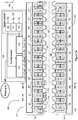
- FIG 1 a shows a schematic illustration of a linear electric drive according to an exemplifying and non-limiting embodiment of the invention.
- the linear electric drive comprises a linear electric machine 100 which is shown as a section view in figure 1 a.
- the section is taken along a line A1-A1 shown in figure 1b and the section plane is parallel with the yz-plane of a coordinate system 199.
- Figure 1b shows a cross-section of the linear electric machine 100.
- the cross-section is taken along a line A2-A2 shown in figure 1a , and the section plane of the cross-section is parallel with the xy-plane of the coordinate system 199.
- the linear electric machine 100 comprises a primary part 101 and a secondary part 102 which are linearly movable with respect to each other in the longitudinal direction of the linear electric machine 100.
- the longitudinal direction is parallel with the z-axis of the coordinate system 199.
- the primary part 101 comprises primary sections 103 and 104 each of which has an airgap surface.
- the secondary part 102 comprises secondary sections 105 and 106 each of which has an airgap surface that faces towards the air-gap surface of the respective one of the primary sections.
- the primary section 103 comprises a force-generating three-phase winding U1, V1, and W1 for generating, when supplied with currents, a longitudinal magnetic thrust force and a transversal magnetic force.
- the longitudinal magnetic thrust force tends to move the primary part 101 longitudinally with respect to the secondary part 102, and the transversal magnetic force pulls the primary section 103 towards the respective secondary section 105.
- the longitudinal magnetic thrust force is substantially parallel with the z-axis of the coordinate system 199, and the transversal magnetic force is substantially parallel with the y-axis of the coordinate system 199.
- the primary section 105 comprises a force-generating three-phase winding U2, V2, and W2 for generating, when supplied with currents, a longitudinal magnetic thrust force and a transversal magnetic force.
- the longitudinal magnetic thrust force tends to move the primary part 101 longitudinally with respect to the secondary part 102, and the transversal magnetic force pulls the primary section 104 towards the respective secondary section 106.
- the primary sections 103 and 104 are mechanically connected to each other and the secondary sections 105 and 106 are mechanically connected to each other so that the transversal magnetic forces acting on the primary sections 103 and 104 are controllable to cancel each other, to form a resultant having substantially the positive y-direction of the coordinate system 199, or to form a resultant having substantially the negative y-direction of the coordinate system 199.
- the resultant is controllable in one geometric dimension which is substantially parallel with the y-axis of the coordinate system 199.
- the primary sections 103 and 104 are mechanically connected to each other with the aid of a frame structure 125.
- the secondary sections 105 and 106 are mechanically connected to each other so that the airgap surfaces of the secondary sections are facing towards opposite directions and the yoke portions of the secondary sections are towards each other.
- the secondary part 102 is a single mechanical structure which constitutes both of the secondary sections 105 and 106.
- the secondary part 102 can comprise for example electrically insulated ferromagnetic sheets which are stacked on each other in the x-direction of the coordinate system 199.
- the primary part 101 comprises, at a first end-region of the primary part, a first tilt-control winding T1 for generating, when supplied with a first tilt-control current, a first transversal magnetic tilt-control force acting on the first end-region of the primary part.
- the primary part 101 comprises, at the second end-region of the primary part, a second tilt-control winding T2 for generating, when supplied with a second tilt-control current, a second transversal magnetic tilt-control force acting on the second end-region of the primary part.
- the first and second transversal magnetic tilt-control forces acting on the primary section 103 have substantially the negative y-direction of the coordinate system 199.
- An angular deviation between the longitudinal direction of the primary part 101 and the longitudinal direction of the secondary part 102, i.e. the tilting of the primary part 101 with respect to the secondary part 102, can be controlled by controlling the difference between the first and second tilt-control forces.
- the exemplifying linear electric machine illustrated in figures 1a and 1b is a switched flux linear electric machine where each of the primary sections 103 and 104 comprises primary section teeth pitched at uniform first intervals, the coil width of the force-generating windings U1, V1, W1, U2, V2, W2 equals to the first interval, and each of the secondary sections comprises secondary section teeth pitched at uniform second intervals different from the first intervals.
- one of the primary section teeth is denoted with a reference 109 and one of the secondary section teeth is denoted with a reference 110.
- Each primary section tooth which is surrounded by a coil of the force-generating windings comprises two portions successively in the longitudinal direction of the primary part 101 and a permanent magnet located in a gap between the two portions.
- the two portions of the primary section tooth 109 are denoted with references 111 and 112 and the permanent magnet located in the gap between the portions 111 and 112 is denoted with a reference 113.
- the magnetization direction of each permanent magnet is parallel with the longitudinal direction of the primary part 101 so that the magnetization directions of permanent magnets located in adjacent ones of the primary section teeth are opposite to each other.
- the magnetization directions of the permanent magnets are depicted with arrows.
- the primary sections 103 and 104 are shifted with respect to each other in the longitudinal direction, i.e. in the z-direction of the coordinate system 199, in order to smooth the magnetic thrust force, i.e. to reduce undulation of the magnetic thrust force.
- Figure 1c illustrates a linear electric machine 130 according to an exemplifying and non-limiting embodiment of the invention.
- Figure 1c shows the end-regions of the primary part 101 of the linear electric machine 130.
- the linear electric machine 130 can be otherwise similar to the linear electric machine 100 illustrated in figures 1 a and 1b but the linear electric machine 130 comprises tilt-control windings in both of the primary sections 103 and 104.
- the primary section 103 comprises a tilt-control winding T11 at the first end-region and a tilt-control winding T21 at the second end-region.
- the primary section 104 comprises a tilt-control winding T12 at the first end-region and a tilt-control winding T22 at the second end-region.
- Figure 1d illustrates a linear electric machine 140 according to an exemplifying and non-limiting embodiment of the invention.
- Figure 1d shows the end-regions of the primary part 101 of the linear electric machine 140.
- the linear electric machine 140 can be otherwise similar to the linear electric machine 100 illustrated in figures 1 a and 1 b but the primary section 103 of the linear electric machine 140 comprises a tilt-control winding T1 only at the first end-region of the primary part 101.
- the primary section 103 comprises, at the second end-region of the primary part 101, a permanent magnet 107 for generating a transversal magnetic force that acts, when controlling the tilting of the primary part 101, as a counterforce for the transversal magnetic tilt-control force generated with the tilt-control winding T1.
- the counterforce is needed because the magnetic tilt-control force generated with the tilt-control winding T1 can only pull the first end-region of the primary section 103 towards the secondary section 105 but not push the first end-region of the primary section 103 away from secondary section 105.
- Figure 1e illustrates a linear electric machine 150 according to an exemplifying and non-limiting embodiment of the invention.
- Figure 1e shows the end-regions of the primary part 101 of the linear electric machine 150.
- the linear electric machine 150 can be otherwise similar to the linear electric machine 100 illustrated in figures 1 a and 1 b but primary section 103 of the linear electric machine 150 comprises a tilt-control winding T1 only at the first end-region of the primary part 101.
- the primary section 104 comprises, at the first end-region of the primary part 101, a permanent magnet 108 for generating a transversal magnetic force that acts, when controlling the tilting of the primary part 101, as a counterforce for the transversal magnetic tilt-control force generated with the tilt-control winding T1.
- the exemplifying linear electric drive illustrated in figure 1 a further comprises a power electronic converter 160 for controlling the linear electric machine 100.
- the power electronic converter 160 comprises a first current supply section 114 for supplying force-generating currents to the force-generating windings U1, V1, W1, U2, V2, W2 of the linear electric machine 100.
- the power electronic converter 160 comprises a second current supply section 119 for supplying tilt-control currents to the tilt-control windings T1 and T2 of the linear electric machine.
- the current supply section 114 may comprise for example a frequency converter for supplying the force-generating currents.
- the current supply section 119 may comprise for example controllable direct voltage sources for supplying the tilt-control currents.
- the power electronic converter 160 comprises a control system 115 for controlling the first and second current supply sections 114 and 119.
- the control system 115 comprises a first controller section 116 for controlling the force-generating currents in accordance with control information related to a longitudinal magnetic thrust force to be generated by the linear electric machine 100.
- the control system 115 comprises a second controller section 117 for controlling differences of the force-generating currents related to the primary sections 103 and 104 in accordance with position information indicative of the y-directional position of the primary part 101 with respect to the secondary part 102 so as to magnetically levitate the primary part with respect to the secondary part.
- the control system 115 comprises a third controller section 118 for controlling the tilt-control currents in accordance with tilting information indicative of the angular deviation between the longitudinal direction of the primary part 101 and the longitudinal direction of the secondary part 102.
- the above-mentioned position information and the tilting information can be based on for example optical and/or inductive measurements.
- the control system 115 can be implemented with one or more processor circuits each of which can be a programmable processor circuit provided with appropriate software, a dedicated hardware processor such as for example an application specific integrated circuit "ASIC”, or a configurable hardware processor such as for example a field programmable gate array "FPGA”. Furthermore, the control system 115 may comprise one or more memory circuits each of which can be a random access memory "RAM”.
- processor circuits each of which can be a programmable processor circuit provided with appropriate software, a dedicated hardware processor such as for example an application specific integrated circuit "ASIC”, or a configurable hardware processor such as for example a field programmable gate array "FPGA”.
- the control system 115 may comprise one or more memory circuits each of which can be a random access memory "RAM”.
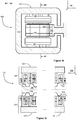
- FIG. 2 illustrates a linear electric machine 200 according to an exemplifying and non-limiting embodiment of the invention.
- the linear electric machine 200 comprises a primary part 201 and a secondary part 202 which are linearly movable with respect to each other in directions parallel with the z-axis of a coordinate system 299.
- the primary part 201 comprises primary sections each having an airgap surface.
- the secondary part 202 comprises secondary sections 205, 206, 215, and 216 each having an airgap surface facing towards the air-gap surface of the respective one of the primary sections.
- Each primary section comprises force-generating windings for generating a longitudinal magnetic thrust force tending to move the primary part 201 longitudinally with respect to the secondary part 202, and a transversal magnetic force pulling the primary section under consideration towards the respective one of the secondary sections.
- the primary sections are mechanically connected to each other and the secondary sections 205, 206, 215, and 216 are mechanically connected to each other so that the resultant of the transversal magnetic forces acting on the primary sections is controllable to be zero or to have a desired direction and a desired strength in the xy-plane of the coordinate system 299.
- the primary part 201 comprises, at one or both end-regions of the primary part 201, one or more tilt-control windings for controlling an angular deviation between the longitudinal direction of the primary part 201 and the longitudinal direction of the secondary part 202.
- the primary sections are not shown in figure 2 but each primary section can be for example similar to the primary section 103 shown in figure 1 a.
- the one or more tilt-control windings are not shown in figure 2 but the one or more tilt-control windings can be according to what is presented in figures 1a , 1b , 1c , 1d, or 1e .
- the exemplifying linear electric machine 200 shown in figure 2 further comprises safety wheels for supporting the primary part 201 with respect to the secondary part 202 in situations in which the magnetic levitation is not operating. In figure 2 , one of the safety wheels is denoted with a reference 240.
- the secondary sections 205, 206, 216, and 216 are mechanically connected to each other so that the airgap surfaces of the secondary sections constitute substantially a square when seen along the longitudinal direction of the secondary part 201, i.e. along a geometric line parallel with the z-axis of the coordinate system 299.
- the secondary sections can be mechanically connected to each other so that the airgap surfaces of the secondary sections constitute substantially a regular polygon when seen along the longitudinal direction of the secondary part.
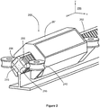
- Figure 3 shows a schematic section view of a conveyor system according to an exemplifying and non-limiting embodiment of the invention.
- the section plane is parallel with the xz-plane of a coordinate system 399.
- the conveyor system is an elevator that comprises a substantially vertical conveyor shaft 320 that can be for example a part of a building e.g. a block of flats.
- the conveyor system comprises a conveyor car 321 movable in the conveyor shaft 320 that represents a mechanical structure defining a moving path of the conveyor car 321.
- the conveyor system comprises a linear electric machine 300 according to an embodiment of the invention for moving the conveyor car 321.
- the conveyor system comprises a power electronic converter 360 according an embodiment of the invention for controlling the linear electric machine 300.
- the linear electric machine 300 comprises a primary part 301 which comprises force-generating windings and one or more tilt-control windings of the kind described above with reference to figures 1a-1e .
- the linear electric machine 300 comprises a secondary part 302 with respect to which the primary part 301 is movable in the vertical directions.
- the primary part 301 of the linear electric machine 300 is attached to the conveyor car 321 and the secondary part 302 is attached to conveyor shaft 320.
- the exemplifying conveyor system illustrated in figure 3 comprises a flexible cable 330 for supplying electric energy to the power electronic converter 360. It is also possible that the conveyor shaft 320 is provided with vertical conductor rails and the conveyor car 321 is provided with trolleys for receiving or supplying electric energy from or to the vertical conductor rails depending on whether the linear electric machine 300 acts as a linear motor or as a linear generator.
Landscapes
- Engineering & Computer Science (AREA)
- Power Engineering (AREA)
- Physics & Mathematics (AREA)
- Chemical & Material Sciences (AREA)
- Combustion & Propulsion (AREA)
- Electromagnetism (AREA)
- Microelectronics & Electronic Packaging (AREA)
- Linear Motors (AREA)
- Types And Forms Of Lifts (AREA)
- Control Of Linear Motors (AREA)
Abstract
Description
- The disclosure relates to a linear electric machine and to a power electronic converter for controlling a linear electric machine. Furthermore, the disclosure relates to a conveyor system comprising a linear electrical machine and a power electronic converter for controlling the linear electric machine. The conveyor system can be for example an elevator or any other conveyor system where a conveyor car is movable along a vertical, horizontal, or inclined path.
- A linear electric machine comprises a primary part and a secondary part which are linearly movable with respect to each other. The primary and secondary parts are provided with magnetically operating means for converting electric energy into linear movement between the primary and secondary parts when the linear electric machine operates as a linear motor, and for converting linear movement between the primary and secondary parts into electric energy when the linear electric machine operates as a linear generator. The magnetically operating means may comprise for example multiphase windings for generating a magnetic field moving with respect to the multiphase windings when alternating currents are supplied to the multiphase windings. Furthermore, the magnetically operating means may comprise equipment for generating a thrust force in response to the moving magnetic field generated with the multiphase windings. The above-mentioned equipment may comprise for example permanent magnets, electromagnets, electrically conductive structures, and/or mechanical structures providing a spatial reluctance variation. The multiphase windings can be located in a movable part of a linear electric machine and the equipment for generating a thrust force in response to a moving magnetic field can be located in a static part of the linear electric machine. It is also possible that the multiphase windings are located in the static part and the equipment for generating the thrust force in response to the moving magnetic field is located in the movable part.
- In many applications, linear electric machines are combined with magnetic levitation where a movable part of a linear electric machine and mechanical structures connected to the movable part are magnetically levitated. An inconvenience related to many systems comprising a magnetically levitated linear electric machine is the complexity of the system because there are first magnetically operating means for generating a thrust force and second magnetically operating means for levitating the movable part and the mechanical structures connected to it.
- The following presents a simplified summary in order to provide a basic understanding of some aspects of various invention embodiments. The summary is not an extensive overview of the invention. It is neither intended to identify key or critical elements of the invention nor to delineate the scope of the invention. The following summary merely presents some concepts of the invention in a simplified form as a prelude to a more detailed description of exemplifying embodiments of the invention.
- In accordance with the invention, there is provided a new linear electric machine that comprises a primary part and a secondary part which are linearly movable with respect to each other. In a linear electric machine according to the invention:
- the primary part comprises primary sections each having an airgap surface,
- the secondary part comprises secondary sections each having an airgap surface facing towards the air-gap surface of the respective one of the primary sections,
- each primary section comprises force-generating windings for generating a longitudinal magnetic thrust force tending to move the primary part longitudinally with respect to the secondary part and a transversal, i.e. normal, magnetic force pulling the primary section under consideration towards the respective one of the secondary sections,
- the primary sections are mechanically connected to each other and the secondary sections are mechanically connected to each other so that the transversal magnetic forces acting on the primary sections are controllable to cancel each other, and
- the primary part comprises, at least at a first end-region of the primary part, one or more tilt-control windings for generating one or more transversal magnetic tilt-control forces so as to control an angular deviation between the longitudinal direction of the primary part and the longitudinal direction of the secondary part.
- In an exemplifying case where there are two primary sections in the primary part and two secondary sections in the secondary part, the secondary sections can mechanically connected to each other for example so that the airgap surfaces of the secondary sections are facing towards opposite directions and the yoke portions of the secondary sections are towards each other. It is also possible that the primary sections are mechanically connected to each other so that the yoke portions of the primary sections are towards each other and the airgap surfaces of the primary sections are facing towards opposite directions. In the above-presented exemplifying cases, the resultant of the transversal magnetic forces acting on the primary sections can be controlled in one geometric dimension which is substantially perpendicular to the longitudinal direction of the linear electric machine. The direction and the strength of the resultant can be controlled by controlling a difference between currents supplied to the force-generating windings of the primary sections.
- In an exemplifying case where there are three or more primary sections in the primary part and correspondingly three or more secondary sections in the secondary part, the secondary sections can be mechanically connected to each other so that the airgap surfaces of the secondary sections constitute substantially a regular polygon, e.g. an equilateral triangle or a square, when seen along the longitudinal direction of the secondary part. In this exemplifying case, the resultant of the transversal magnetic forces acting on the primary sections can be controlled in two geometric dimensions which are substantially perpendicular to the longitudinal direction of the linear electric machine.
- It is, however, challenging to control the currents supplied to the force-generating windings so that, in addition to achieving a desired thrust force and a desired resultant of the transversal magnetic forces, tilting of the primary part with respect to the secondary part is kept within acceptable limits. In this document, the term "tilting" means an angular deviation between the longitudinal direction of the primary part and the longitudinal direction of the secondary part. The tilting can be controlled with the aid of the above-mentioned one or more tilt-control windings for generating the one or more transversal magnetic tilt-control forces acting on one or both of the end-regions of the primary part.
- In accordance with the invention, there is provided also a new power electronic converter for controlling a linear electric machine according to the invention. A power electronic converter according to the invention comprises:
- a first current supply section for supplying force-generating currents to the force-generating windings of the linear electric machine,
- a first controller section for controlling the force-generating currents in accordance with control information related to a longitudinal magnetic thrust force to be generated by the linear electric machine,
- a second controller section for controlling differences of the force-generating currents related to different ones of the primary sections in accordance with position information indicative of a transversal position of the primary part of the linear electric machine with respect to the secondary part of the linear electric machine so as to magnetically levitate the primary part with respect to the secondary part,
- a second current supply section for supplying one or more tilt-control currents to the one or more tilt-control windings of the linear electric machine, and
- a third controller section for controlling the one or more tilt-control currents in accordance with tilting information indicative of an angular deviation between
- the longitudinal direction of the primary part of the linear electric machine and the longitudinal direction of the secondary part of the linear electric machine.
- The above-mentioned position information and the tilting information can be based on for example optical and/or inductive measurements.
- A linear electric drive according to the invention comprises a linear electric machine according to the invention and a power electronic converter according to the invention for controlling the linear electric machine.
- In accordance with the invention, there is provided also a new conveyor system that comprises:
- a conveyor car,
- a linear electric machine according to the invention for moving the conveyor car, and
- a power electronic converter according to the invention for controlling the linear electric machine.
- The conveyor system can be, for example but not necessarily, an elevator where the movement of the conveyor car is substantially vertical.
- A number of exemplifying and non-limiting embodiments of the invention are described in accompanied dependent claims.
- Various exemplifying and non-limiting embodiments of the invention both as to constructions and to methods of operation, together with additional objects and advantages thereof, will be best understood from the following description of specific exemplifying and non-limiting embodiments when read in connection with the accompanying drawings.
- The verbs "to comprise" and "to include" are used in this document as open limitations that neither exclude nor require the existence of un-recited features. The features recited in dependent claims are mutually freely combinable unless otherwise explicitly stated. Furthermore, it is to be understood that the use of "a" or "an", i.e. a singular form, throughout this document does not exclude a plurality.
- Exemplifying and non-limiting embodiments of the invention and their advantages are explained in greater detail below in the sense of examples and with reference to the accompanying drawings, in which:
- f
igures 1a ,1b ,1c ,1d, and 1e illustrate a linear electric drive according to an exemplifying and non-limiting embodiment of the invention, and linear electric machines according to exemplifying and non-limiting embodiments of the invention, -
figure 2 illustrates a linear electric machine according to an exemplifying and non-limiting embodiment of the invention, and -
figure 3 shows a schematic illustration of a conveyor system according to an exemplifying and non-limiting embodiment of the invention. - The specific examples provided in the description given below should not be construed as limiting the scope and/or the applicability of the appended claims. Lists and groups of examples provided in the description given below are not exhaustive unless otherwise explicitly stated.
-
Figure 1 a shows a schematic illustration of a linear electric drive according to an exemplifying and non-limiting embodiment of the invention. The linear electric drive comprises a linearelectric machine 100 which is shown as a section view infigure 1 a. The section is taken along a line A1-A1 shown infigure 1b and the section plane is parallel with the yz-plane of a coordinatesystem 199.Figure 1b shows a cross-section of the linearelectric machine 100. The cross-section is taken along a line A2-A2 shown infigure 1a , and the section plane of the cross-section is parallel with the xy-plane of the coordinatesystem 199. - The linear
electric machine 100 comprises aprimary part 101 and asecondary part 102 which are linearly movable with respect to each other in the longitudinal direction of the linearelectric machine 100. The longitudinal direction is parallel with the z-axis of the coordinatesystem 199. Theprimary part 101 comprisesprimary sections secondary part 102 comprisessecondary sections - The
primary section 103 comprises a force-generating three-phase winding U1, V1, and W1 for generating, when supplied with currents, a longitudinal magnetic thrust force and a transversal magnetic force. The longitudinal magnetic thrust force tends to move theprimary part 101 longitudinally with respect to thesecondary part 102, and the transversal magnetic force pulls theprimary section 103 towards the respectivesecondary section 105. The longitudinal magnetic thrust force is substantially parallel with the z-axis of the coordinatesystem 199, and the transversal magnetic force is substantially parallel with the y-axis of the coordinatesystem 199. Correspondingly, theprimary section 105 comprises a force-generating three-phase winding U2, V2, and W2 for generating, when supplied with currents, a longitudinal magnetic thrust force and a transversal magnetic force. The longitudinal magnetic thrust force tends to move theprimary part 101 longitudinally with respect to thesecondary part 102, and the transversal magnetic force pulls theprimary section 104 towards the respectivesecondary section 106. - As illustrated in
figures 1 a and 1 b, theprimary sections secondary sections primary sections system 199, or to form a resultant having substantially the negative y-direction of the coordinatesystem 199. Thus, the resultant is controllable in one geometric dimension which is substantially parallel with the y-axis of the coordinatesystem 199. As illustrated infigure 1b , theprimary sections frame structure 125. Thesecondary sections secondary part 102 is a single mechanical structure which constitutes both of thesecondary sections secondary sections secondary part 102 can comprise for example electrically insulated ferromagnetic sheets which are stacked on each other in the x-direction of the coordinatesystem 199. - The
primary part 101 comprises, at a first end-region of the primary part, a first tilt-control winding T1 for generating, when supplied with a first tilt-control current, a first transversal magnetic tilt-control force acting on the first end-region of the primary part. Theprimary part 101 comprises, at the second end-region of the primary part, a second tilt-control winding T2 for generating, when supplied with a second tilt-control current, a second transversal magnetic tilt-control force acting on the second end-region of the primary part. The first and second transversal magnetic tilt-control forces acting on theprimary section 103 have substantially the negative y-direction of the coordinatesystem 199. An angular deviation between the longitudinal direction of theprimary part 101 and the longitudinal direction of thesecondary part 102, i.e. the tilting of theprimary part 101 with respect to thesecondary part 102, can be controlled by controlling the difference between the first and second tilt-control forces. - The exemplifying linear electric machine illustrated in
figures 1a and1b is a switched flux linear electric machine where each of theprimary sections figure 1a , one of the primary section teeth is denoted with areference 109 and one of the secondary section teeth is denoted with areference 110. Each primary section tooth which is surrounded by a coil of the force-generating windings comprises two portions successively in the longitudinal direction of theprimary part 101 and a permanent magnet located in a gap between the two portions. Infigure 1a , the two portions of theprimary section tooth 109 are denoted withreferences portions reference 113. The magnetization direction of each permanent magnet is parallel with the longitudinal direction of theprimary part 101 so that the magnetization directions of permanent magnets located in adjacent ones of the primary section teeth are opposite to each other. Infigure 1a , the magnetization directions of the permanent magnets are depicted with arrows. In a linear electric machine according to an exemplifying and non-limiting embodiment of the invention, theprimary sections system 199, in order to smooth the magnetic thrust force, i.e. to reduce undulation of the magnetic thrust force. -
Figure 1c illustrates a linearelectric machine 130 according to an exemplifying and non-limiting embodiment of the invention.Figure 1c shows the end-regions of theprimary part 101 of the linearelectric machine 130. The linearelectric machine 130 can be otherwise similar to the linearelectric machine 100 illustrated infigures 1 a and 1b but the linearelectric machine 130 comprises tilt-control windings in both of theprimary sections primary section 103 comprises a tilt-control winding T11 at the first end-region and a tilt-control winding T21 at the second end-region. Theprimary section 104 comprises a tilt-control winding T12 at the first end-region and a tilt-control winding T22 at the second end-region. -
Figure 1d illustrates a linearelectric machine 140 according to an exemplifying and non-limiting embodiment of the invention.Figure 1d shows the end-regions of theprimary part 101 of the linearelectric machine 140. The linearelectric machine 140 can be otherwise similar to the linearelectric machine 100 illustrated infigures 1 a and 1 b but theprimary section 103 of the linearelectric machine 140 comprises a tilt-control winding T1 only at the first end-region of theprimary part 101. Theprimary section 103 comprises, at the second end-region of theprimary part 101, apermanent magnet 107 for generating a transversal magnetic force that acts, when controlling the tilting of theprimary part 101, as a counterforce for the transversal magnetic tilt-control force generated with the tilt-control winding T1. The counterforce is needed because the magnetic tilt-control force generated with the tilt-control winding T1 can only pull the first end-region of theprimary section 103 towards thesecondary section 105 but not push the first end-region of theprimary section 103 away fromsecondary section 105. -
Figure 1e illustrates a linearelectric machine 150 according to an exemplifying and non-limiting embodiment of the invention.Figure 1e shows the end-regions of theprimary part 101 of the linearelectric machine 150. The linearelectric machine 150 can be otherwise similar to the linearelectric machine 100 illustrated infigures 1 a and 1 b butprimary section 103 of the linearelectric machine 150 comprises a tilt-control winding T1 only at the first end-region of theprimary part 101. Theprimary section 104 comprises, at the first end-region of theprimary part 101, apermanent magnet 108 for generating a transversal magnetic force that acts, when controlling the tilting of theprimary part 101, as a counterforce for the transversal magnetic tilt-control force generated with the tilt-control winding T1. - The exemplifying linear electric drive illustrated in
figure 1 a further comprises a powerelectronic converter 160 for controlling the linearelectric machine 100. The powerelectronic converter 160 comprises a firstcurrent supply section 114 for supplying force-generating currents to the force-generating windings U1, V1, W1, U2, V2, W2 of the linearelectric machine 100. The powerelectronic converter 160 comprises a secondcurrent supply section 119 for supplying tilt-control currents to the tilt-control windings T1 and T2 of the linear electric machine. Thecurrent supply section 114 may comprise for example a frequency converter for supplying the force-generating currents. Thecurrent supply section 119 may comprise for example controllable direct voltage sources for supplying the tilt-control currents. The powerelectronic converter 160 comprises acontrol system 115 for controlling the first and secondcurrent supply sections control system 115 comprises afirst controller section 116 for controlling the force-generating currents in accordance with control information related to a longitudinal magnetic thrust force to be generated by the linearelectric machine 100. Thecontrol system 115 comprises asecond controller section 117 for controlling differences of the force-generating currents related to theprimary sections primary part 101 with respect to thesecondary part 102 so as to magnetically levitate the primary part with respect to the secondary part. Thecontrol system 115 comprises athird controller section 118 for controlling the tilt-control currents in accordance with tilting information indicative of the angular deviation between the longitudinal direction of theprimary part 101 and the longitudinal direction of thesecondary part 102. The above-mentioned position information and the tilting information can be based on for example optical and/or inductive measurements. - The
control system 115 can be implemented with one or more processor circuits each of which can be a programmable processor circuit provided with appropriate software, a dedicated hardware processor such as for example an application specific integrated circuit "ASIC", or a configurable hardware processor such as for example a field programmable gate array "FPGA". Furthermore, thecontrol system 115 may comprise one or more memory circuits each of which can be a random access memory "RAM". -
Figure 2 illustrates a linearelectric machine 200 according to an exemplifying and non-limiting embodiment of the invention. The linearelectric machine 200 comprises aprimary part 201 and asecondary part 202 which are linearly movable with respect to each other in directions parallel with the z-axis of a coordinatesystem 299. Theprimary part 201 comprises primary sections each having an airgap surface. Thesecondary part 202 comprisessecondary sections primary part 201 longitudinally with respect to thesecondary part 202, and a transversal magnetic force pulling the primary section under consideration towards the respective one of the secondary sections. The primary sections are mechanically connected to each other and thesecondary sections system 299. Theprimary part 201 comprises, at one or both end-regions of theprimary part 201, one or more tilt-control windings for controlling an angular deviation between the longitudinal direction of theprimary part 201 and the longitudinal direction of thesecondary part 202. The primary sections are not shown infigure 2 but each primary section can be for example similar to theprimary section 103 shown infigure 1 a. The one or more tilt-control windings are not shown infigure 2 but the one or more tilt-control windings can be according to what is presented infigures 1a ,1b ,1c ,1d, or 1e . The exemplifying linearelectric machine 200 shown infigure 2 further comprises safety wheels for supporting theprimary part 201 with respect to thesecondary part 202 in situations in which the magnetic levitation is not operating. Infigure 2 , one of the safety wheels is denoted with areference 240. - In the exemplifying linear electric drive illustrated in
figure 2 , thesecondary sections secondary part 201, i.e. along a geometric line parallel with the z-axis of the coordinatesystem 299. In cases where the number of the secondary sections is at least three, the secondary sections can be mechanically connected to each other so that the airgap surfaces of the secondary sections constitute substantially a regular polygon when seen along the longitudinal direction of the secondary part. -
Figure 3 shows a schematic section view of a conveyor system according to an exemplifying and non-limiting embodiment of the invention. The section plane is parallel with the xz-plane of a coordinatesystem 399. In this exemplifying case, the conveyor system is an elevator that comprises a substantiallyvertical conveyor shaft 320 that can be for example a part of a building e.g. a block of flats. The conveyor system comprises aconveyor car 321 movable in theconveyor shaft 320 that represents a mechanical structure defining a moving path of theconveyor car 321. The conveyor system comprises a linearelectric machine 300 according to an embodiment of the invention for moving theconveyor car 321. The conveyor system comprises a powerelectronic converter 360 according an embodiment of the invention for controlling the linearelectric machine 300. The linearelectric machine 300 comprises aprimary part 301 which comprises force-generating windings and one or more tilt-control windings of the kind described above with reference tofigures 1a-1e . The linearelectric machine 300 comprises asecondary part 302 with respect to which theprimary part 301 is movable in the vertical directions. - In this exemplifying conveyor system, the
primary part 301 of the linearelectric machine 300 is attached to theconveyor car 321 and thesecondary part 302 is attached toconveyor shaft 320. The exemplifying conveyor system illustrated infigure 3 comprises aflexible cable 330 for supplying electric energy to the powerelectronic converter 360. It is also possible that theconveyor shaft 320 is provided with vertical conductor rails and theconveyor car 321 is provided with trolleys for receiving or supplying electric energy from or to the vertical conductor rails depending on whether the linearelectric machine 300 acts as a linear motor or as a linear generator. - The specific examples provided in the description given above should not be construed as limiting the applicability and/or the interpretation of the appended claims. Lists and groups of examples provided in the description given above are not exhaustive unless otherwise explicitly stated.
Claims (14)
- A linear electric machine (100, 130, 140, 150, 200) comprising a primary part (101, 201) and a secondary part (102, 202) which are linearly movable with respect to each other, wherein:- the primary part comprises primary sections (103, 104) each having an airgap surface,- the secondary part comprises secondary sections (105, 106, 205, 206, 215, 216) each having an airgap surface facing towards the air-gap surface of a respective one of the primary sections,- each primary section comprises force-generating windings (U1, V1, W1, U2, V2, W2) for generating a longitudinal magnetic thrust force tending to move the primary part longitudinally with respect to the secondary part and a transversal magnetic force pulling the primary section towards a respective one of the secondary sections, and- the primary sections are mechanically connected to each other and the secondary sections are mechanically connected to each other so that the transversal magnetic forces acting on the primary sections are controllable to cancel each other,characterized in that the primary part comprises, at least at a first end-region of the primary part, one or more tilt-control windings (T1, T11, T12) for generating one or more transversal magnetic tilt-control forces so as to control an angular deviation between a longitudinal direction of the primary part and a longitudinal direction of the secondary part.
- A linear electric machine according to claim 1, wherein the primary part comprises, at a second end-region of the primary part, one or more other tilt-control windings (T2, T21, T22) for generating one or more other transversal magnetic tilt-control forces.
- A linear electric machine according to any of claims 1-3, wherein the primary part comprises, at a second end-region of the primary part, a permanent magnet (107) for generating a transversal magnetic force for acting, when controlling the angular deviation, against the transversal magnetic tilt-control force generated with the tilt-control winding (T1) at the first end-region of the primary part.
- A linear electric machine according to claim 1-3, wherein the primary part comprises, at the first end-region of the primary part, a permanent magnet (108) for generating a transversal magnetic force for acting, when controlling the angular deviation, against the transversal magnetic tilt-control force generated with the tilt-control winding (T1) at the first end-region of the primary part.
- A linear electric machine according to any of claims 1-4, wherein the secondary sections (105, 106) are mechanically connected to each other so that the air-gap surfaces of the secondary sections are facing towards opposite directions and yoke portions of the secondary sections are towards each other.
- A linear electric machine according to any of claims 1-4, wherein the secondary sections (205, 206, 216, 216) are mechanically connected to each other so that the airgap surfaces of the secondary sections constitute substantially a regular polygon when seen along the longitudinal direction of the secondary part.
- A linear electric machine according to claim 6, wherein the secondary sections (205, 206, 216, 216) are mechanically connected to each other so that the airgap surfaces of the secondary sections constitute substantially a square when seen along the longitudinal direction of the secondary part.
- A linear electric machine according to any of claims 1-7, wherein the linear electric machine is a switched flux linear electric machine where each primary section comprises primary section teeth (109) pitched at uniform first intervals, a coil width of the force-generating windings equals to the first intervals, and each secondary section comprises secondary section teeth (110) pitched at uniform second intervals different from the first intervals.
- A linear electric machine according to claim 8, wherein each primary section tooth which is surrounded by a coil of the force-generating windings comprises two portions (111, 112) successively in the longitudinal direction of the primary part and a permanent magnet (113) located in a gap between the two portions, magnetization directions of the permanent magnets being parallel with the longitudinal direction of the primary part and the permanent magnets of adjacent ones of the primary section teeth having magnetization directions opposite to each other.
- A power electronic converter (160) for controlling a linear electric machine according to any of claims 1-9, the power electronic converter comprising:- a first current supply section (114) for supplying force-generating currents to the force-generating windings of the linear electric machine,- a first controller section (116) for controlling the force-generating currents in accordance with control information related to a longitudinal magnetic thrust force to be generated by the linear electric machine, and- a second controller section (117) for controlling differences of the force-generating currents related to different ones of the primary sections in accordance with position information indicative of a transversal position of the primary part of the linear electric machine with respect to the secondary part of the linear electric machine so as to magnetically levitate the primary part with respect to the secondary part,characterized in that the power electronic converter further comprises:- a second current supply section (119) for supplying one or more tilt-control currents to the one or more tilt-control windings of the linear electric machine, and- a third controller section (118) for controlling the one or more tilt-control currents in accordance with tilting information indicative of an angular deviation between the longitudinal direction of the primary part of the linear electric machine and the longitudinal direction of the secondary part of the linear electric machine.
- A linear electric drive comprising a linear electric machine (100) according to any of claims 1-9 and a power electronic converter 160 according to claim 10 for controlling the linear electric machine.
- A conveyor system comprising:- a conveyor car (321),- a linear electric machine (300) according to any of claims 1-9 for moving the conveyor car, and- a power electronic converter (360) according to claim 10 for controlling the linear electric machine.
- A conveyor system according to claim 12, wherein the primary part of the linear electric machine (300) is attached to the conveyor car and the secondary part of the linear electric machine is attached to a mechanical structure defining a moving path of the conveyor car.
- A conveyor system according to claim 12 or 13, wherein the conveyor system is an elevator where the movement of the conveyor car is substantially vertical.
Priority Applications (7)
| Application Number | Priority Date | Filing Date | Title |
|---|---|---|---|
| EP20171688.3A EP3703231B1 (en) | 2016-10-28 | 2016-10-28 | A power electronic converter for controlling a linear electric machine |
| EP16196217.0A EP3316460B1 (en) | 2016-10-28 | 2016-10-28 | A linear electric machine and a power electronic converter for controlling the linear electric machine |
| JP2019521121A JP6970194B2 (en) | 2016-10-28 | 2017-10-25 | Power electronics converters for controlling linear electromechanical machines and linear electromechanical machines |
| CN201780063913.XA CN109906546B (en) | 2016-10-28 | 2017-10-25 | Linear motor and power electronic converter for controlling linear motor |
| KR1020197012068A KR102466299B1 (en) | 2016-10-28 | 2017-10-25 | Power electronic converters for linear electromechanical and linear electromechanical control |
| PCT/EP2017/077230 WO2018077916A1 (en) | 2016-10-28 | 2017-10-25 | A linear electric machine and a power electronic converter for controlling the linear electric machine |
| US16/334,903 US11183916B2 (en) | 2016-10-28 | 2017-10-25 | Linear electric machine and a power electronic converter for controlling the linear electric machine |
Applications Claiming Priority (1)
| Application Number | Priority Date | Filing Date | Title |
|---|---|---|---|
| EP16196217.0A EP3316460B1 (en) | 2016-10-28 | 2016-10-28 | A linear electric machine and a power electronic converter for controlling the linear electric machine |
Related Child Applications (2)
| Application Number | Title | Priority Date | Filing Date |
|---|---|---|---|
| EP20171688.3A Division-Into EP3703231B1 (en) | 2016-10-28 | 2016-10-28 | A power electronic converter for controlling a linear electric machine |
| EP20171688.3A Division EP3703231B1 (en) | 2016-10-28 | 2016-10-28 | A power electronic converter for controlling a linear electric machine |
Publications (2)
| Publication Number | Publication Date |
|---|---|
| EP3316460A1 true EP3316460A1 (en) | 2018-05-02 |
| EP3316460B1 EP3316460B1 (en) | 2020-07-01 |
Family
ID=57211366
Family Applications (2)
| Application Number | Title | Priority Date | Filing Date |
|---|---|---|---|
| EP20171688.3A Active EP3703231B1 (en) | 2016-10-28 | 2016-10-28 | A power electronic converter for controlling a linear electric machine |
| EP16196217.0A Active EP3316460B1 (en) | 2016-10-28 | 2016-10-28 | A linear electric machine and a power electronic converter for controlling the linear electric machine |
Family Applications Before (1)
| Application Number | Title | Priority Date | Filing Date |
|---|---|---|---|
| EP20171688.3A Active EP3703231B1 (en) | 2016-10-28 | 2016-10-28 | A power electronic converter for controlling a linear electric machine |
Country Status (6)
| Country | Link |
|---|---|
| US (1) | US11183916B2 (en) |
| EP (2) | EP3703231B1 (en) |
| JP (1) | JP6970194B2 (en) |
| KR (1) | KR102466299B1 (en) |
| CN (1) | CN109906546B (en) |
| WO (1) | WO2018077916A1 (en) |
Cited By (2)
| Publication number | Priority date | Publication date | Assignee | Title |
|---|---|---|---|---|
| EP3666715A1 (en) * | 2018-12-13 | 2020-06-17 | KONE Corporation | Electric linear motor and elevator |
| EP3760565A1 (en) * | 2019-07-05 | 2021-01-06 | KONE Corporation | Electric linear motor |
Families Citing this family (5)
| Publication number | Priority date | Publication date | Assignee | Title |
|---|---|---|---|---|
| DE102018118814A1 (en) | 2018-08-02 | 2020-02-06 | Beckhoff Automation Gmbh | Method for identifying a carriage of a linear transport system |
| CN109713872B (en) * | 2019-01-08 | 2021-02-02 | 河北科技大学 | High-thrust linear motor |
| FI20195489A1 (en) * | 2019-06-10 | 2020-12-11 | Lappeenrannan Lahden Teknillinen Yliopisto Lut | A linear electric machine |
| US11309783B2 (en) * | 2019-09-26 | 2022-04-19 | Honeywell Federal Manufacturing & Technologies, Llc | Electromagnetic propulsion system |
| CN111431373B (en) * | 2020-04-09 | 2021-06-15 | 哈尔滨工业大学 | Control rod driving mechanism based on polygonal linear reluctance motor |
Citations (8)
| Publication number | Priority date | Publication date | Assignee | Title |
|---|---|---|---|---|
| US4463290A (en) * | 1980-06-06 | 1984-07-31 | Fujitsu Limited | Induction type positioning system |
| WO1998058866A2 (en) * | 1997-06-19 | 1998-12-30 | Kone Corporation | Elevator with linear rotor |
| JP2005168243A (en) * | 2003-12-04 | 2005-06-23 | Yaskawa Electric Corp | Permanent magnet type synchronous linear motor |
| DE102005004380A1 (en) * | 2005-01-31 | 2006-08-10 | Siemens Ag | Linear motor with force ripple compensation |
| DE102005007489A1 (en) * | 2005-02-17 | 2006-08-24 | Siemens Ag | Woodworking machine with linear direct drive |
| EP2131477A2 (en) * | 2008-06-04 | 2009-12-09 | Korea Institute Of Science And Technology | Linear stepping motor |
| US20120262095A1 (en) * | 2010-06-02 | 2012-10-18 | Smith James S | Air gap control systems and methods |
| CN102255470B (en) * | 2011-06-10 | 2013-03-27 | 哈尔滨工业大学 | LPMSM (linear permanent magnet synchronous motor) with low-thrust fluctuation |
Family Cites Families (5)
| Publication number | Priority date | Publication date | Assignee | Title |
|---|---|---|---|---|
| KR100426616B1 (en) | 2002-04-25 | 2004-04-14 | 한국과학기술연구원 | Bearingless linear motor |
| DE102006009271A1 (en) * | 2006-02-28 | 2007-08-30 | BSH Bosch und Siemens Hausgeräte GmbH | Linear drive, has stator comprising magnetic field guiding core that has legs extending with respective foot, which has angular surface and magnets, where lengths of magnets, breadths of legs and distances of legs are varied along axis |
| WO2009122954A1 (en) * | 2008-04-02 | 2009-10-08 | 日産自動車株式会社 | Electrically-powered actuator driving control apparatus and driving control method and vehicle having electrically-powered actuator driving control apparatus |
| JP6303029B2 (en) | 2015-01-07 | 2018-03-28 | 株式会社日立製作所 | Motor system and compressor |
| JP6304560B2 (en) * | 2015-03-12 | 2018-04-04 | 株式会社安川電機 | Linear motor, linear motor control system |
-
2016
- 2016-10-28 EP EP20171688.3A patent/EP3703231B1/en active Active
- 2016-10-28 EP EP16196217.0A patent/EP3316460B1/en active Active
-
2017
- 2017-10-25 US US16/334,903 patent/US11183916B2/en active Active
- 2017-10-25 JP JP2019521121A patent/JP6970194B2/en active Active
- 2017-10-25 KR KR1020197012068A patent/KR102466299B1/en active IP Right Grant
- 2017-10-25 WO PCT/EP2017/077230 patent/WO2018077916A1/en active Application Filing
- 2017-10-25 CN CN201780063913.XA patent/CN109906546B/en active Active
Patent Citations (8)
| Publication number | Priority date | Publication date | Assignee | Title |
|---|---|---|---|---|
| US4463290A (en) * | 1980-06-06 | 1984-07-31 | Fujitsu Limited | Induction type positioning system |
| WO1998058866A2 (en) * | 1997-06-19 | 1998-12-30 | Kone Corporation | Elevator with linear rotor |
| JP2005168243A (en) * | 2003-12-04 | 2005-06-23 | Yaskawa Electric Corp | Permanent magnet type synchronous linear motor |
| DE102005004380A1 (en) * | 2005-01-31 | 2006-08-10 | Siemens Ag | Linear motor with force ripple compensation |
| DE102005007489A1 (en) * | 2005-02-17 | 2006-08-24 | Siemens Ag | Woodworking machine with linear direct drive |
| EP2131477A2 (en) * | 2008-06-04 | 2009-12-09 | Korea Institute Of Science And Technology | Linear stepping motor |
| US20120262095A1 (en) * | 2010-06-02 | 2012-10-18 | Smith James S | Air gap control systems and methods |
| CN102255470B (en) * | 2011-06-10 | 2013-03-27 | 哈尔滨工业大学 | LPMSM (linear permanent magnet synchronous motor) with low-thrust fluctuation |
Cited By (2)
| Publication number | Priority date | Publication date | Assignee | Title |
|---|---|---|---|---|
| EP3666715A1 (en) * | 2018-12-13 | 2020-06-17 | KONE Corporation | Electric linear motor and elevator |
| EP3760565A1 (en) * | 2019-07-05 | 2021-01-06 | KONE Corporation | Electric linear motor |
Also Published As
| Publication number | Publication date |
|---|---|
| EP3316460B1 (en) | 2020-07-01 |
| EP3703231B1 (en) | 2021-09-22 |
| EP3703231A1 (en) | 2020-09-02 |
| JP2019534667A (en) | 2019-11-28 |
| CN109906546A (en) | 2019-06-18 |
| KR20190069452A (en) | 2019-06-19 |
| KR102466299B1 (en) | 2022-11-10 |
| CN109906546B (en) | 2021-02-26 |
| US20190214896A1 (en) | 2019-07-11 |
| WO2018077916A1 (en) | 2018-05-03 |
| JP6970194B2 (en) | 2021-11-24 |
| US11183916B2 (en) | 2021-11-23 |
Similar Documents
| Publication | Publication Date | Title |
|---|---|---|
| EP3703231B1 (en) | A power electronic converter for controlling a linear electric machine | |
| US6633217B2 (en) | Inductrack magnet configuration | |
| US6758146B2 (en) | Laminated track design for inductrack maglev systems | |
| EP2999652B1 (en) | Self-propelled elevator with wireless power supply | |
| US6664880B2 (en) | Inductrack magnet configuration | |
| US8044541B2 (en) | Multi-degree-of-freedom actuator and stage device | |
| WO2003002370A1 (en) | Improved inductrack configuration | |
| KR20120018588A (en) | Linear motor | |
| KR20140109932A (en) | Linear synchronous motor | |
| US6833638B2 (en) | Integrated system for non-contact power feed device and permanent magnet-excited transverse flux linear motor | |
| US20090140583A1 (en) | Synchronous Linear Motor | |
| Cho et al. | Design considerations of EM-PM hybrid levitation and propulsion device for magnetically levitated vehicle | |
| US11025186B2 (en) | Electric linear motor, elevator and method for controlling rotation of a mover with respect to a stator beam of an electric linear motor | |
| US11784550B2 (en) | Permanent field magnet, manufacturing method, and linear motor | |
| US11012019B2 (en) | Electric linear motor, elevator and method for controlling rotation of a mover with respect to a stator beam of an electric linear motor | |
| KR100639265B1 (en) | Magnetically levitated transportation system with increased guidance force | |
| JP6056571B2 (en) | Linear motor | |
| WO2020249850A1 (en) | A linear electric machine | |
| US20220069691A1 (en) | Linear motor | |
| CN220857885U (en) | Linear motor | |
| KR101266167B1 (en) | Actuator having valance mechanism for 3 direction by the 2-way magnetism inducted, The magnetic bearing and Magnetic levitation apparatus thereof | |
| US20230006529A1 (en) | Transport device | |
| Vadde | Electromagnetic computational analysis of double sided linear switched reluctance motor for reduction of force ripples | |
| JPH07288967A (en) | Noncontact conveyer apparatus | |
| JP2018121374A (en) | Multi-axis actuator and power transmission method of the same |
Legal Events
| Date | Code | Title | Description |
|---|---|---|---|
| PUAI | Public reference made under article 153(3) epc to a published international application that has entered the european phase |
Free format text: ORIGINAL CODE: 0009012 |
|
| STAA | Information on the status of an ep patent application or granted ep patent |
Free format text: STATUS: THE APPLICATION HAS BEEN PUBLISHED |
|
| AK | Designated contracting states |
Kind code of ref document: A1 Designated state(s): AL AT BE BG CH CY CZ DE DK EE ES FI FR GB GR HR HU IE IS IT LI LT LU LV MC MK MT NL NO PL PT RO RS SE SI SK SM TR |
|
| AX | Request for extension of the european patent |
Extension state: BA ME |
|
| RAP1 | Party data changed (applicant data changed or rights of an application transferred) |
Owner name: DANFOSS MOBILE ELECTRIFICATION OY |
|
| STAA | Information on the status of an ep patent application or granted ep patent |
Free format text: STATUS: REQUEST FOR EXAMINATION WAS MADE |
|
| 17P | Request for examination filed |
Effective date: 20181023 |
|
| RBV | Designated contracting states (corrected) |
Designated state(s): AL AT BE BG CH CY CZ DE DK EE ES FI FR GB GR HR HU IE IS IT LI LT LU LV MC MK MT NL NO PL PT RO RS SE SI SK SM TR |
|
| GRAP | Despatch of communication of intention to grant a patent |
Free format text: ORIGINAL CODE: EPIDOSNIGR1 |
|
| STAA | Information on the status of an ep patent application or granted ep patent |
Free format text: STATUS: GRANT OF PATENT IS INTENDED |
|
| INTG | Intention to grant announced |
Effective date: 20200304 |
|
| GRAS | Grant fee paid |
Free format text: ORIGINAL CODE: EPIDOSNIGR3 |
|
| RAP1 | Party data changed (applicant data changed or rights of an application transferred) |
Owner name: DANFOSS EDITRON OY |
|
| GRAA | (expected) grant |
Free format text: ORIGINAL CODE: 0009210 |
|
| STAA | Information on the status of an ep patent application or granted ep patent |
Free format text: STATUS: THE PATENT HAS BEEN GRANTED |
|
| AK | Designated contracting states |
Kind code of ref document: B1 Designated state(s): AL AT BE BG CH CY CZ DE DK EE ES FI FR GB GR HR HU IE IS IT LI LT LU LV MC MK MT NL NO PL PT RO RS SE SI SK SM TR |
|
| REG | Reference to a national code |
Ref country code: CH Ref legal event code: EP Ref country code: AT Ref legal event code: REF Ref document number: 1287110 Country of ref document: AT Kind code of ref document: T Effective date: 20200715 |
|
| REG | Reference to a national code |
Ref country code: IE Ref legal event code: FG4D |
|
| REG | Reference to a national code |
Ref country code: DE Ref legal event code: R096 Ref document number: 602016039024 Country of ref document: DE |
|
| REG | Reference to a national code |
Ref country code: SE Ref legal event code: TRGR |
|
| REG | Reference to a national code |
Ref country code: NO Ref legal event code: T2 Effective date: 20200701 |
|
| REG | Reference to a national code |
Ref country code: FI Ref legal event code: FGE |
|
| REG | Reference to a national code |
Ref country code: LT Ref legal event code: MG4D |
|
| PG25 | Lapsed in a contracting state [announced via postgrant information from national office to epo] |
Ref country code: BG Free format text: LAPSE BECAUSE OF FAILURE TO SUBMIT A TRANSLATION OF THE DESCRIPTION OR TO PAY THE FEE WITHIN THE PRESCRIBED TIME-LIMIT Effective date: 20201001 |
|
| REG | Reference to a national code |
Ref country code: NL Ref legal event code: MP Effective date: 20200701 |
|
| REG | Reference to a national code |
Ref country code: AT Ref legal event code: MK05 Ref document number: 1287110 Country of ref document: AT Kind code of ref document: T Effective date: 20200701 |
|
| PG25 | Lapsed in a contracting state [announced via postgrant information from national office to epo] |
Ref country code: ES Free format text: LAPSE BECAUSE OF FAILURE TO SUBMIT A TRANSLATION OF THE DESCRIPTION OR TO PAY THE FEE WITHIN THE PRESCRIBED TIME-LIMIT Effective date: 20200701 Ref country code: GR Free format text: LAPSE BECAUSE OF FAILURE TO SUBMIT A TRANSLATION OF THE DESCRIPTION OR TO PAY THE FEE WITHIN THE PRESCRIBED TIME-LIMIT Effective date: 20201002 Ref country code: PT Free format text: LAPSE BECAUSE OF FAILURE TO SUBMIT A TRANSLATION OF THE DESCRIPTION OR TO PAY THE FEE WITHIN THE PRESCRIBED TIME-LIMIT Effective date: 20201102 Ref country code: AT Free format text: LAPSE BECAUSE OF FAILURE TO SUBMIT A TRANSLATION OF THE DESCRIPTION OR TO PAY THE FEE WITHIN THE PRESCRIBED TIME-LIMIT Effective date: 20200701 Ref country code: CZ Free format text: LAPSE BECAUSE OF FAILURE TO SUBMIT A TRANSLATION OF THE DESCRIPTION OR TO PAY THE FEE WITHIN THE PRESCRIBED TIME-LIMIT Effective date: 20200701 Ref country code: LT Free format text: LAPSE BECAUSE OF FAILURE TO SUBMIT A TRANSLATION OF THE DESCRIPTION OR TO PAY THE FEE WITHIN THE PRESCRIBED TIME-LIMIT Effective date: 20200701 Ref country code: HR Free format text: LAPSE BECAUSE OF FAILURE TO SUBMIT A TRANSLATION OF THE DESCRIPTION OR TO PAY THE FEE WITHIN THE PRESCRIBED TIME-LIMIT Effective date: 20200701 |
|
| PG25 | Lapsed in a contracting state [announced via postgrant information from national office to epo] |
Ref country code: PL Free format text: LAPSE BECAUSE OF FAILURE TO SUBMIT A TRANSLATION OF THE DESCRIPTION OR TO PAY THE FEE WITHIN THE PRESCRIBED TIME-LIMIT Effective date: 20200701 Ref country code: LV Free format text: LAPSE BECAUSE OF FAILURE TO SUBMIT A TRANSLATION OF THE DESCRIPTION OR TO PAY THE FEE WITHIN THE PRESCRIBED TIME-LIMIT Effective date: 20200701 Ref country code: RS Free format text: LAPSE BECAUSE OF FAILURE TO SUBMIT A TRANSLATION OF THE DESCRIPTION OR TO PAY THE FEE WITHIN THE PRESCRIBED TIME-LIMIT Effective date: 20200701 Ref country code: IS Free format text: LAPSE BECAUSE OF FAILURE TO SUBMIT A TRANSLATION OF THE DESCRIPTION OR TO PAY THE FEE WITHIN THE PRESCRIBED TIME-LIMIT Effective date: 20201101 |
|
| PG25 | Lapsed in a contracting state [announced via postgrant information from national office to epo] |
Ref country code: NL Free format text: LAPSE BECAUSE OF FAILURE TO SUBMIT A TRANSLATION OF THE DESCRIPTION OR TO PAY THE FEE WITHIN THE PRESCRIBED TIME-LIMIT Effective date: 20200701 |
|
| REG | Reference to a national code |
Ref country code: DE Ref legal event code: R097 Ref document number: 602016039024 Country of ref document: DE |
|
| PG25 | Lapsed in a contracting state [announced via postgrant information from national office to epo] |
Ref country code: DK Free format text: LAPSE BECAUSE OF FAILURE TO SUBMIT A TRANSLATION OF THE DESCRIPTION OR TO PAY THE FEE WITHIN THE PRESCRIBED TIME-LIMIT Effective date: 20200701 Ref country code: RO Free format text: LAPSE BECAUSE OF FAILURE TO SUBMIT A TRANSLATION OF THE DESCRIPTION OR TO PAY THE FEE WITHIN THE PRESCRIBED TIME-LIMIT Effective date: 20200701 Ref country code: SM Free format text: LAPSE BECAUSE OF FAILURE TO SUBMIT A TRANSLATION OF THE DESCRIPTION OR TO PAY THE FEE WITHIN THE PRESCRIBED TIME-LIMIT Effective date: 20200701 Ref country code: EE Free format text: LAPSE BECAUSE OF FAILURE TO SUBMIT A TRANSLATION OF THE DESCRIPTION OR TO PAY THE FEE WITHIN THE PRESCRIBED TIME-LIMIT Effective date: 20200701 |
|
| PLBE | No opposition filed within time limit |
Free format text: ORIGINAL CODE: 0009261 |
|
| STAA | Information on the status of an ep patent application or granted ep patent |
Free format text: STATUS: NO OPPOSITION FILED WITHIN TIME LIMIT |
|
| PG25 | Lapsed in a contracting state [announced via postgrant information from national office to epo] |
Ref country code: AL Free format text: LAPSE BECAUSE OF FAILURE TO SUBMIT A TRANSLATION OF THE DESCRIPTION OR TO PAY THE FEE WITHIN THE PRESCRIBED TIME-LIMIT Effective date: 20200701 |
|
| REG | Reference to a national code |
Ref country code: CH Ref legal event code: PL |
|
| 26N | No opposition filed |
Effective date: 20210406 |
|
| PG25 | Lapsed in a contracting state [announced via postgrant information from national office to epo] |
Ref country code: SK Free format text: LAPSE BECAUSE OF FAILURE TO SUBMIT A TRANSLATION OF THE DESCRIPTION OR TO PAY THE FEE WITHIN THE PRESCRIBED TIME-LIMIT Effective date: 20200701 Ref country code: LU Free format text: LAPSE BECAUSE OF NON-PAYMENT OF DUE FEES Effective date: 20201028 Ref country code: MC Free format text: LAPSE BECAUSE OF FAILURE TO SUBMIT A TRANSLATION OF THE DESCRIPTION OR TO PAY THE FEE WITHIN THE PRESCRIBED TIME-LIMIT Effective date: 20200701 |
|
| REG | Reference to a national code |
Ref country code: BE Ref legal event code: MM Effective date: 20201031 |
|
| PG25 | Lapsed in a contracting state [announced via postgrant information from national office to epo] |
Ref country code: LI Free format text: LAPSE BECAUSE OF NON-PAYMENT OF DUE FEES Effective date: 20201031 Ref country code: SI Free format text: LAPSE BECAUSE OF FAILURE TO SUBMIT A TRANSLATION OF THE DESCRIPTION OR TO PAY THE FEE WITHIN THE PRESCRIBED TIME-LIMIT Effective date: 20200701 Ref country code: BE Free format text: LAPSE BECAUSE OF NON-PAYMENT OF DUE FEES Effective date: 20201031 Ref country code: CH Free format text: LAPSE BECAUSE OF NON-PAYMENT OF DUE FEES Effective date: 20201031 |
|
| PG25 | Lapsed in a contracting state [announced via postgrant information from national office to epo] |
Ref country code: IE Free format text: LAPSE BECAUSE OF NON-PAYMENT OF DUE FEES Effective date: 20201028 |
|
| PG25 | Lapsed in a contracting state [announced via postgrant information from national office to epo] |
Ref country code: TR Free format text: LAPSE BECAUSE OF FAILURE TO SUBMIT A TRANSLATION OF THE DESCRIPTION OR TO PAY THE FEE WITHIN THE PRESCRIBED TIME-LIMIT Effective date: 20200701 Ref country code: MT Free format text: LAPSE BECAUSE OF FAILURE TO SUBMIT A TRANSLATION OF THE DESCRIPTION OR TO PAY THE FEE WITHIN THE PRESCRIBED TIME-LIMIT Effective date: 20200701 Ref country code: CY Free format text: LAPSE BECAUSE OF FAILURE TO SUBMIT A TRANSLATION OF THE DESCRIPTION OR TO PAY THE FEE WITHIN THE PRESCRIBED TIME-LIMIT Effective date: 20200701 |
|
| PG25 | Lapsed in a contracting state [announced via postgrant information from national office to epo] |
Ref country code: MK Free format text: LAPSE BECAUSE OF FAILURE TO SUBMIT A TRANSLATION OF THE DESCRIPTION OR TO PAY THE FEE WITHIN THE PRESCRIBED TIME-LIMIT Effective date: 20200701 |
|
| P01 | Opt-out of the competence of the unified patent court (upc) registered |
Effective date: 20230617 |
|
| PGFP | Annual fee paid to national office [announced via postgrant information from national office to epo] |
Ref country code: IT Payment date: 20230913 Year of fee payment: 8 Ref country code: GB Payment date: 20230907 Year of fee payment: 8 |
|
| PGFP | Annual fee paid to national office [announced via postgrant information from national office to epo] |
Ref country code: SE Payment date: 20230912 Year of fee payment: 8 Ref country code: FR Payment date: 20230921 Year of fee payment: 8 |
|
| PGFP | Annual fee paid to national office [announced via postgrant information from national office to epo] |
Ref country code: NO Payment date: 20231010 Year of fee payment: 8 Ref country code: FI Payment date: 20231011 Year of fee payment: 8 Ref country code: DE Payment date: 20230906 Year of fee payment: 8 |
|
| REG | Reference to a national code |
Ref country code: NO Ref legal event code: CREP Ref country code: NO Ref legal event code: CHAD Owner name: DANFOSS A/S, DK |
|
| REG | Reference to a national code |
Ref country code: GB Ref legal event code: 732E Free format text: REGISTERED BETWEEN 20240229 AND 20240306 |