EP3316411B1 - Electrical connector apparatus having a male housing and a female housing with ribs - Google Patents
Electrical connector apparatus having a male housing and a female housing with ribs Download PDFInfo
- Publication number
- EP3316411B1 EP3316411B1 EP17207739.8A EP17207739A EP3316411B1 EP 3316411 B1 EP3316411 B1 EP 3316411B1 EP 17207739 A EP17207739 A EP 17207739A EP 3316411 B1 EP3316411 B1 EP 3316411B1
- Authority
- EP
- European Patent Office
- Prior art keywords
- tpa
- housing
- male housing
- electrical connector
- female housing
- Prior art date
- Legal status (The legal status is an assumption and is not a legal conclusion. Google has not performed a legal analysis and makes no representation as to the accuracy of the status listed.)
- Active
Links
- 230000004888 barrier function Effects 0.000 description 2
- 230000001681 protective effect Effects 0.000 description 2
Images


Classifications
-
- H—ELECTRICITY
- H01—ELECTRIC ELEMENTS
- H01R—ELECTRICALLY-CONDUCTIVE CONNECTIONS; STRUCTURAL ASSOCIATIONS OF A PLURALITY OF MUTUALLY-INSULATED ELECTRICAL CONNECTING ELEMENTS; COUPLING DEVICES; CURRENT COLLECTORS
- H01R13/00—Details of coupling devices of the kinds covered by groups H01R12/70 or H01R24/00 - H01R33/00
- H01R13/40—Securing contact members in or to a base or case; Insulating of contact members
- H01R13/42—Securing in a demountable manner
- H01R13/436—Securing a plurality of contact members by one locking piece or operation
- H01R13/4361—Insertion of locking piece perpendicular to direction of contact insertion
- H01R13/4362—Insertion of locking piece perpendicular to direction of contact insertion comprising a temporary and a final locking position
-
- H—ELECTRICITY
- H01—ELECTRIC ELEMENTS
- H01R—ELECTRICALLY-CONDUCTIVE CONNECTIONS; STRUCTURAL ASSOCIATIONS OF A PLURALITY OF MUTUALLY-INSULATED ELECTRICAL CONNECTING ELEMENTS; COUPLING DEVICES; CURRENT COLLECTORS
- H01R43/00—Apparatus or processes specially adapted for manufacturing, assembling, maintaining, or repairing of line connectors or current collectors or for joining electric conductors
- H01R43/26—Apparatus or processes specially adapted for manufacturing, assembling, maintaining, or repairing of line connectors or current collectors or for joining electric conductors for engaging or disengaging the two parts of a coupling device
Definitions
- the present invention generally relates to an electrical connector apparatus with a male housing and a female housing having a terminal position assurance device (TPA). More particularly, the invention is directed to ribs and other protective features provided on the male housing and the female housing to prevent the TPA from moving from a pre-set position to a final lock position.
- TPA terminal position assurance device
- the present invention relates to a female housing of an electrical connector apparatus according to claim 1, a male housing of an electrical connector apparatus according to claim 2, an electrical connector apparatus according to claim 3 and to a method for assembling an electrical connector apparatus according to claim 4.
- At least a terminal is provided into each of the male housing and the female housing, when each of their respective TPA is at a pre-set position.
- the set of terminals provided for the male housing is secured thereto when the TPA thereof is placed at the final lock position.
- the set of terminals provided for the female housing is secured thereto when the TPA of the female housing is placed at the final lock position. Thereafter, the male housing and the female housing may be engaged together.
- the male housing and the female housing are provided with ribs to protect the TPA from physical contact. These ribs create a physical protective barrier to prevent the TPA from being moved from the pre-set position to the final lock position.
- the electrical connector apparatus of the present invention is assembled and packaged in bags in bulk and shipped with the TPA in the pre-set position. This way, the operator can insert terminals into the electrical connector apparatus immediately upon receiving the electrical connector apparatus.
- FIG. 1 is an exploded view showing the electrical connector apparatus of the present invention, generally referred to as reference number 1.
- the electrical connector apparatus 1 includes a male housing 2 and a female housing 3.
- TPA 4 is provided in the male housing 2 and TPA 5 is provided in the female housing 3.
- FIG. 1 shows ribs 6, 7, 8, 9, 10, and 11 of the male housing 2.
- Ribs 6, 7, 8, 9, 10, and 11 are provided on the male housing 2 in order to protect the TPA 4 from any physical contact. Therefore, when the TPA 4 is set in the pre-set position during shipping, the ribs 6, 7, 8, 9, 10, and 11 will prevent the TPA 4 from moving to the final lock position. Furthermore, the ribs 6, 7, 8, 9, 10, and 11 are located on the periphery of the TPA 4 so as to protect the TPA 4 from all sides.
- the male housing has a set of terminal apertures for receiving therein a set of other terminals.
- the male housing also comprises an opening for receiving the female housing.
- FIG. 2A depicts a cross-sectional view of the male housing 2 in which the TPA 4 is in the pre-set position. This is the position in which the male housing 2 of the electrical connector apparatus 1 is shipped.
- FIG 2B shows a cross-sectional view of the male housing 2 in which the TPA 4 is in the final lock position. This final lock position makes inserting the terminals into the electrical connector apparatus more difficult for the operator; therefore, it is preferable that the TPA 4 is not moved to the final lock position during shipping.
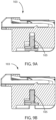
- FIG. 3A illustrates a cross-sectional view of the female housing 3 with the TPA 5 in the pre-set position. Similar to the male housing 2, this is the position in which the female housing 3 of the electrical connector apparatus 1 is shipped.
- FIG. 3B shows a cross-sectional view of the female housing 3 in which the TPA 5 is in the final lock position. As explained above, it is preferable that the TPA 5 is not moved to this final lock position during shipping and/or handling.
- FIG. 4A illustrates a perspective view of the female housing 3 of the electrical connector apparatus 1 showing the TPA 5 in the pre-set position.
- TPA 5 is located on the bottom, or underneath,of the female housing 3 in a bottom slot.
- the female housing has a set of terminal apertures for receiving therein at least a set of terminals.
- FIG. 4A further shows ribs 12, 13, 14, 15, 16, 17, and 18 that are provided on the bottom side of the female housing 3 and that surround the TPA 5 so as to prevent the TPA 5 from being physically pressed down into the final lock position during shipping, handling, or at any other time prior to reaching the operator.
- the ribs 12, 13, 14, 15, 16, 17, and 18 are located on the periphery of the TPA 5 so as to protect the TPA 5 from all sides.
- FIG 4B shows the female housing 3 of the electrical connector apparatus 1 once the TPA 5 has been moved to the final lock position.
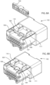
- FIG. 5A illustrates a perspective view of the male housing 2 of the electrical connector apparatus 1 showing the TPA 4 in the pre-set position.
- the TPA 4 is protected by the ribs 6, 7, 8, 9, 10, and 11 from all sides. These ribs 6, 7, 8, 9, 10, and 11 are located on the periphery of the TPA 4 so as to protect the TPA 4 from being pressed down into the final lock position.
- FIG. 5B A perspective view of the male housing with the TPA 4 pressed down into the final lock position is shown in FIG. 5B .
- FIG. 6 , FIG. 7 , FIG. 8A, FIG. 8B , FIG, 9A, FIG. 9B , FIG. 10A, FIG. 10B , FIG. 11A and FIG. 11B illustrate an electrical connector apparatus according to the second embodiment of the present invention.
- the second embodiment of the present invention includes electrical connector apparatus 100,TPA 104, and TPA 105 having 16pins.
- the present invention is not limited to any specific number of pins for the electrical connector apparatus or TPA.
- the male housing, the female housing, the TPA, and the ribs operate identically to the first embodiment, as detailed above.
- Figure 6 illustrates an exploded perspective view of the electrical connector apparatus 100 according to the second embodiment of the present invention.
- Electrical connector apparatus 100 includes male housing 102, TPA 104, female housing 103, and TPA 105. Furthermore, Figure 6 shows the ribs 106, 107, 108, 109, 110, and 111 provided on the male housing 102 to protect the TPA 104.
- Figure 7 is a perspective view depicting the male housing 102 of the electrical connector apparatus 100 with the TPA 104 in the pre-set position.
- Ribs 106, 107, 108, 109, 110, and 111 are provided on the male housing 102 so as to surround the TPA 104 along the periphery of the TPA 104.
- Ribs 106, 107, 108, 109, 110, and 111 protect the TPA 104 so that the TPA 104 is not moved from a pre-set position to a final lock position during shipping and/or handling.
- Figure 8A illustrates a perspective view of the male housing 102 of the electrical connector apparatus 100 with the TPA 104 removed in order to fully see the placement of the TPA 104 in the male housing 102.
- Figure 8B shows the male housing 102 once the TPA 104 has been inserted into the male housing 102 and set in the pre-set position.
- the female housing 103 is also provided with ribs 112, 113, 114, 115, 116, 117, and 118 to protect the TPA 103 from being moved from a pre-set position, as shown in Figure 11A , to the final lock position, as shown in Figure 11B .
- These ribs 112, 113, 114, 115, 116, 117, and 118 are located on the periphery of the TPA 103 so as to create a physical barrier to protect the TPA 103 from all sides.
- the TPA 105 of the female housing 103 can be in either a pre-set position or a final lock position.
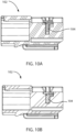
- the TPA 104 of the male housing 102 can be in either a pre-set position, as shown in Figure 10A , or a final lock position, as shown in Figure 10B .
Landscapes
- Connector Housings Or Holding Contact Members (AREA)
Description
- The present invention generally relates to an electrical connector apparatus with a male housing and a female housing having a terminal position assurance device (TPA). More particularly, the invention is directed to ribs and other protective features provided on the male housing and the female housing to prevent the TPA from moving from a pre-set position to a final lock position.
US 6,135,802 A andUS 5,830,013 A describe variants of connectors. - The present invention relates to a female housing of an electrical connector apparatus according to
claim 1, a male housing of an electrical connector apparatus according toclaim 2, an electrical connector apparatus according toclaim 3 and to a method for assembling an electrical connector apparatus according toclaim 4. - At least a terminal is provided into each of the male housing and the female housing, when each of their respective TPA is at a pre-set position. The set of terminals provided for the male housing is secured thereto when the TPA thereof is placed at the final lock position. Similarly, the set of terminals provided for the female housing is secured thereto when the TPA of the female housing is placed at the final lock position. Thereafter, the male housing and the female housing may be engaged together.
- To ensure that the TPA provided in the male housing and the TPA provided in the female housing of the electrical connector apparatus is not moved from a pre-set position to a final lock position during shipping and/or handling, the male housing and the female housing are provided with ribs to protect the TPA from physical contact. These ribs create a physical protective barrier to prevent the TPA from being moved from the pre-set position to the final lock position.
- The electrical connector apparatus of the present invention is assembled and packaged in bags in bulk and shipped with the TPA in the pre-set position. This way, the operator can insert terminals into the electrical connector apparatus immediately upon receiving the electrical connector apparatus.
- However, since the electrical connector apparatus is packaged and shipped in bulk, various parts can make contact with the TPA during shipping and/or handling which can cause an unprotected TPA from being moved from the pre-set position to the final lock position. If this occurs, the operator of the electrical connector apparatus will have to reset the TPA from the final position to the pre-set position in order to insert the terminals. This causes an inconvenience to the operator as well as wastes time when inserting the terminals into the electrical connector apparatus.
- Additional features, advantages, and embodiments of the invention are set forth apparent from consideration of the following detailed description, drawings, and claims. Moreover, it is to be understood that both the foregoing summary of the invention and the following detailed description are exemplary and intended to provide further explanations without limiting the scope of the invention as claimed.
-
-
FIG. 1 is an exploded perspective view of the electrical connector apparatus of the present invention including the male housing, the female housing, and the TPA. -
FIG. 2A is a cross-sectional view of the first embodiment of the present invention showing the male housing of the electrical connector apparatus with the TPA in the pre-set position. -
FIG. 2B is a cross-sectional view of the first embodiment of the present invention showing the male housing of the electrical connector apparatus with the TPA in the final lock position. -
FIG. 3A is a cross-sectional view of the first embodiment of the present invention showing the female housing of the electrical connector apparatus with the TPA in the pre-set position. -
FIG. 3B is a cross-sectional view of the first embodiment of the present invention showing the female housing of the electrical connector apparatus with the TPA in the final lock position. -
FIG. 4A is a perspective view of first embodiment of the present invention showing the female housing of the electrical connector apparatus with the TPA in the pre-set position. -
FIG. 4B is a perspective view of first embodiment of the present invention showing the female housing of the electrical connector apparatus with the TPA in the final lock position. -
FIG. 5A is a perspective view of the first embodiment of the present invention showing the male housing of the electrical connector apparatus with the TPA in the pre-set position. -
FIG. 5B is a perspective view of the first embodiment of the present invention showing the male housing of the electrical connector apparatus with the TPA in the final lock position. -
FIG. 6 is an exploded perspective view of the second embodiment of the present invention showing the electrical connector assembling including the male housing, the female housing, and the TPA. -
FIG. 7 is a perspective view of the second embodiment of the present invention showing the male housing of the electrical connector with the TPA in the pre-set position. -
FIG. 8A is a perspective view of the second embodiment of the present invention showing the male housing and the TPA of the electrical connector apparatus. -
FIG. 8B is a perspective view of the second embodiment of the present invention showing the male housing of the electrical connector with the TPA in the pre-set position. -
FIG. 9A is a cross-sectional view of the second embodiment of the present invention showing the female housing of the electrical connector apparatus with the TPA in the pre-set position. -
FIG. 9B is a cross-sectional view of the second embodiment of the present invention showing the female housing of the electrical connector apparatus with the TPA in the final lock position. -
FIG. 10A is a cross-sectional view of the second embodiment of the present invention showing the male housing of the electrical connector apparatus with the TPA in the pre-set position. -
FIG. 10B is a cross-sectional view of the second embodiment of the present invention showing the male housing of the electrical connector apparatus with the TPA in the final lock position. -
FIG. 11A is a perspective view of the second embodiment of the present invention showing the female housing of the electrical connector apparatus with the TPA in the pre-set position. -
FIG. 11B is a perspective view of the second embodiment of the present invention showing the female housing of the electrical connector apparatus with the TPA in the final lock position. -
FIG. 1 is an exploded view showing the electrical connector apparatus of the present invention, generally referred to asreference number 1. Theelectrical connector apparatus 1 includes amale housing 2 and afemale housing 3. TPA 4 is provided in themale housing 2 and TPA 5 is provided in thefemale housing 3. Additionally,FIG. 1 showsribs male housing 2. -
Ribs male housing 2 in order to protect theTPA 4 from any physical contact. Therefore, when theTPA 4 is set in the pre-set position during shipping, theribs TPA 4 from moving to the final lock position. Furthermore, theribs TPA 4 so as to protect theTPA 4 from all sides. - Furthermore, as can be seen in
Figure 1 , the male housing has a set of terminal apertures for receiving therein a set of other terminals. The male housing also comprises an opening for receiving the female housing. -
FIG. 2A depicts a cross-sectional view of themale housing 2 in which theTPA 4 is in the pre-set position. This is the position in which themale housing 2 of theelectrical connector apparatus 1 is shipped.FIG 2B shows a cross-sectional view of themale housing 2 in which theTPA 4 is in the final lock position. This final lock position makes inserting the terminals into the electrical connector apparatus more difficult for the operator; therefore, it is preferable that theTPA 4 is not moved to the final lock position during shipping. -
FIG. 3A illustrates a cross-sectional view of thefemale housing 3 with theTPA 5 in the pre-set position. Similar to themale housing 2, this is the position in which thefemale housing 3 of theelectrical connector apparatus 1 is shipped.FIG. 3B shows a cross-sectional view of thefemale housing 3 in which theTPA 5 is in the final lock position. As explained above, it is preferable that theTPA 5 is not moved to this final lock position during shipping and/or handling. -
FIG. 4A illustrates a perspective view of thefemale housing 3 of theelectrical connector apparatus 1 showing theTPA 5 in the pre-set position.TPA 5 is located on the bottom, or underneath,of thefemale housing 3 in a bottom slot. Additionally, the female housing has a set of terminal apertures for receiving therein at least a set of terminals. -
FIG. 4A further showsribs female housing 3 and that surround theTPA 5 so as to prevent theTPA 5 from being physically pressed down into the final lock position during shipping, handling, or at any other time prior to reaching the operator. Theribs TPA 5 so as to protect theTPA 5 from all sides.FIG 4B shows thefemale housing 3 of theelectrical connector apparatus 1 once theTPA 5 has been moved to the final lock position. -
FIG. 5A illustrates a perspective view of themale housing 2 of theelectrical connector apparatus 1 showing theTPA 4 in the pre-set position. As can be seen inFIG. 5A , when theTPA 4 is in the pre-set position, during shipping or at any other time, theTPA 4 is protected by theribs ribs TPA 4 so as to protect theTPA 4 from being pressed down into the final lock position. A perspective view of the male housing with theTPA 4 pressed down into the final lock position is shown inFIG. 5B . -
FIG. 6 ,FIG. 7 ,FIG. 8A, FIG. 8B ,FIG, 9A, FIG. 9B ,FIG. 10A, FIG. 10B ,FIG. 11A and FIG. 11B illustrate an electrical connector apparatus according to the second embodiment of the present invention. Specifically, the second embodiment of the present invention includeselectrical connector apparatus 100,TPA 104, andTPA 105 having 16pins. However, the present invention is not limited to any specific number of pins for the electrical connector apparatus or TPA. - In the second embodiment of the present invention, the male housing, the female housing, the TPA, and the ribs operate identically to the first embodiment, as detailed above.
- Specifically,
Figure 6 illustrates an exploded perspective view of theelectrical connector apparatus 100 according to the second embodiment of the present invention.Electrical connector apparatus 100 includesmale housing 102,TPA 104,female housing 103, andTPA 105. Furthermore,Figure 6 shows theribs male housing 102 to protect theTPA 104. -
Figure 7 is a perspective view depicting themale housing 102 of theelectrical connector apparatus 100 with theTPA 104 in the pre-set position.Ribs male housing 102 so as to surround theTPA 104 along the periphery of theTPA 104.Ribs TPA 104 so that theTPA 104 is not moved from a pre-set position to a final lock position during shipping and/or handling. -
Figure 8A illustrates a perspective view of themale housing 102 of theelectrical connector apparatus 100 with theTPA 104 removed in order to fully see the placement of theTPA 104 in themale housing 102.Figure 8B shows themale housing 102 once theTPA 104 has been inserted into themale housing 102 and set in the pre-set position. - The
female housing 103 is also provided withribs TPA 103 from being moved from a pre-set position, as shown inFigure 11A , to the final lock position, as shown inFigure 11B . Theseribs TPA 103 so as to create a physical barrier to protect theTPA 103 from all sides. - As can be seen in
Figures 9A and 9B , theTPA 105 of thefemale housing 103 can be in either a pre-set position or a final lock position. Similarly, theTPA 104 of themale housing 102 can be in either a pre-set position, as shown inFigure 10A , or a final lock position, as shown inFigure 10B .
Claims (4)
- A female housing (3; 103) of an electrical connector apparatus (1; 100), comprising:a set of terminal apertures for receiving therein at least a set of terminals;a bottom slot located underneath the female housing (3; 103); anda first terminal position assurance device (5; 105) (TPA) accommodated within the bottom slot,characterised in that the female housing further comprises:ribs (12, 13, 14, 15, 16, 17, 18; 112, 113, 114, 115, 116, 117, 118) provided on the female housing (3; 103) along a periphery of the TPA (5; 105) to protect the TPA (5; 105) from physical contact, wherein the firstTPA (5; 105) includes at each of its widthwise outer sides two rib-shaped engagement members extending therefrom for allowing the first TPA (5; 105) to be at a pre-set position during transport of the female housing (3; 103) and at a final lock position for engaging the set of terminals.
- A male housing (2; 102) of an electrical connector apparatus (1; 100), comprising:a set of terminal apertures for receiving therein a set of other terminals;a second terminal position assurance device (4; 104) (TPA);an opening for receiving the second TPA (4; 104);a first end having the set of terminal apertures for receiving therein the set of other terminals;wherein the male housing (2; 102) is configured to receive the female housing (3; 103) into a second end of the male housing (2; 102),characterised in thatthe male housing further comprises:ribs (6, 7, 8, 9, 10, 11; 106, 107, 108, 109, 110, 111) provided on the male housing (2; 102) along a periphery of the second TPA (4; 104) to protect the second TPA (4; 104) from physical contact, wherein the male housing (2; 102) is configured to receive the female housing (3; 103) into a second end of the male housing (2; 102), wherein the secondTPA (4; 104) includes at each of its widthwise outer sides two rib-shaped engagement members extending therefrom for allowing the second TPA (4; 104) to be at a pre-set position during transport of the male housing (2; 102) and at a final lock position for engaging the set of other terminals.
- An electrical connector apparatus (1; 100), comprising:a female housing (3; 103) according to claim 1, anda male housing (2; 102) according to claim 2,characterized in that the ribs (6, 7, 8, 9, 10, 11; 106, 107, 108, 109, 110, 111) on the male housing (2; 102) are configured to extend beyond the second TPA, when the second TPA is at a pre-set position, to protect the second TPA (4; 104) from physical contact.
- A method for assembling an electrical connector apparatus (1; 100), comprising the steps of:providing a female housing (3; 103) according to claim 1;accommodating a first terminal position assurance device (5; 105) (TPA) within a bottom slot located underneath the female housing (3; 103);providing a male housing (2; 102) according to claim 2;accommodating a second terminal position assurance device (4; 104) (TPA) within an opening of the male housing (2; 102);accommodating the female housing (3; 103) into the male housing (2; 102); whereinthe step of accommodating the first TPA (5; 105) within the bottom slot located underneath the female housing (3; 103) further comprises the step of providing the first TPA (5; 105) at each of its widthwise outer sides with two rib-shaped engagement members extending therefrom for allowing the first TPA (5; 105) to be at a pre-set position during transport of the female housing (3; 103) and to be at a final lock position for engaging the set of terminals; and whereinthe step of accommodating the second TPA (4; 104) within the opening of the male housing (2; 102) further comprises the step of providing the second TPA (4; 104) at each of its widthwise outer sides with two rib-shaped engagement members extending therefrom for allowing the second TPA (4; 104) device to be at a pre-set position during transport of the male housing (2; 102) and at a final lock position for engaging the set of terminals.
Applications Claiming Priority (1)
| Application Number | Priority Date | Filing Date | Title |
|---|---|---|---|
| US15/405,654 US10109955B2 (en) | 2016-01-14 | 2017-01-13 | Electrical connector apparatus having a male housing and a female housing with ribs |
Publications (2)
| Publication Number | Publication Date |
|---|---|
| EP3316411A1 EP3316411A1 (en) | 2018-05-02 |
| EP3316411B1 true EP3316411B1 (en) | 2024-04-03 |
Family
ID=60673707
Family Applications (1)
| Application Number | Title | Priority Date | Filing Date |
|---|---|---|---|
| EP17207739.8A Active EP3316411B1 (en) | 2017-01-13 | 2017-12-15 | Electrical connector apparatus having a male housing and a female housing with ribs |
Country Status (1)
| Country | Link |
|---|---|
| EP (1) | EP3316411B1 (en) |
Citations (1)
| Publication number | Priority date | Publication date | Assignee | Title |
|---|---|---|---|---|
| US20170207577A1 (en) * | 2016-01-14 | 2017-07-20 | J.S.T. Corporation | Electrical connector apparatus having a male housing and a female housing with ribs |
Family Cites Families (4)
| Publication number | Priority date | Publication date | Assignee | Title |
|---|---|---|---|---|
| US5830013A (en) * | 1997-03-07 | 1998-11-03 | Yazaki Corporation | Electric connector |
| JP3278051B2 (en) * | 1997-12-25 | 2002-04-30 | 住友電装株式会社 | Connector with cover |
| US7278890B1 (en) * | 2006-07-26 | 2007-10-09 | Delphi Technologies, Inc. | Electrical connector with secondary lock |
| US10103487B2 (en) * | 2015-12-21 | 2018-10-16 | J.S.T. Corporation | Connector latch |
-
2017
- 2017-12-15 EP EP17207739.8A patent/EP3316411B1/en active Active
Patent Citations (1)
| Publication number | Priority date | Publication date | Assignee | Title |
|---|---|---|---|---|
| US20170207577A1 (en) * | 2016-01-14 | 2017-07-20 | J.S.T. Corporation | Electrical connector apparatus having a male housing and a female housing with ribs |
Also Published As
| Publication number | Publication date |
|---|---|
| EP3316411A1 (en) | 2018-05-02 |
Similar Documents
| Publication | Publication Date | Title |
|---|---|---|
| US10109955B2 (en) | Electrical connector apparatus having a male housing and a female housing with ribs | |
| US9954311B2 (en) | Electric connector | |
| KR101809330B1 (en) | Connector having protect plate | |
| JP6265803B2 (en) | connector | |
| US6702616B1 (en) | Retaining terminal structure of connector | |
| EP2899813B1 (en) | Connector | |
| EP2930793A1 (en) | Connector | |
| US8845351B2 (en) | Connector housing with alignment guidance feature | |
| US20170170601A1 (en) | Connector position assurance device, a connector apparatus having male and female connector assemblies with terminal position assurance devices and the connector position assurance device, a male connector assembly, a female connector assembly, and a method for assembling the connector apparatus | |
| CN107799989B (en) | Lever type connector | |
| EP2852264B1 (en) | Electronics module with a side entry connection | |
| US9843126B1 (en) | Connector housing assemblies with access hood and push surface | |
| CN108832427A (en) | Connector assembly for security system | |
| US9986635B2 (en) | Assembly and electronic device with conductive mesh | |
| EP3316411B1 (en) | Electrical connector apparatus having a male housing and a female housing with ribs | |
| EP3113295B1 (en) | Connector | |
| US8827741B2 (en) | Housing insert contact protection | |
| EP2705580B1 (en) | Electrical connector plug with key to avoid contact damage | |
| EP3648259A2 (en) | Electrical connector with latches and terminal position assurance projections provided on hinged cover | |
| JP2009117059A (en) | Connector | |
| CN103582982B (en) | There is the direct plug connector elements of shielded direct contact | |
| EP2937949B1 (en) | Connector for motor vehicles and process for mounting of this connector | |
| EP3108542B1 (en) | Improved electrical connector | |
| TWM447019U (en) | Network electrical connector with fool-proof structure | |
| EP3300179B1 (en) | Electrical connector with male blade stabilizer |
Legal Events
| Date | Code | Title | Description |
|---|---|---|---|
| PUAI | Public reference made under article 153(3) epc to a published international application that has entered the european phase |
Free format text: ORIGINAL CODE: 0009012 |
|
| STAA | Information on the status of an ep patent application or granted ep patent |
Free format text: STATUS: THE APPLICATION HAS BEEN PUBLISHED |
|
| AK | Designated contracting states |
Kind code of ref document: A1 Designated state(s): AL AT BE BG CH CY CZ DE DK EE ES FI FR GB GR HR HU IE IS IT LI LT LU LV MC MK MT NL NO PL PT RO RS SE SI SK SM TR |
|
| AX | Request for extension of the european patent |
Extension state: BA ME |
|
| STAA | Information on the status of an ep patent application or granted ep patent |
Free format text: STATUS: REQUEST FOR EXAMINATION WAS MADE |
|
| 17P | Request for examination filed |
Effective date: 20180810 |
|
| RBV | Designated contracting states (corrected) |
Designated state(s): AL AT BE BG CH CY CZ DE DK EE ES FI FR GB GR HR HU IE IS IT LI LT LU LV MC MK MT NL NO PL PT RO RS SE SI SK SM TR |
|
| STAA | Information on the status of an ep patent application or granted ep patent |
Free format text: STATUS: EXAMINATION IS IN PROGRESS |
|
| 17Q | First examination report despatched |
Effective date: 20190117 |
|
| STAA | Information on the status of an ep patent application or granted ep patent |
Free format text: STATUS: EXAMINATION IS IN PROGRESS |
|
| STAA | Information on the status of an ep patent application or granted ep patent |
Free format text: STATUS: EXAMINATION IS IN PROGRESS |
|
| RIC1 | Information provided on ipc code assigned before grant |
Ipc: H01R 43/26 20060101ALN20210915BHEP Ipc: H01R 13/436 20060101AFI20210915BHEP |
|
| GRAP | Despatch of communication of intention to grant a patent |
Free format text: ORIGINAL CODE: EPIDOSNIGR1 |
|
| STAA | Information on the status of an ep patent application or granted ep patent |
Free format text: STATUS: GRANT OF PATENT IS INTENDED |
|
| RIC1 | Information provided on ipc code assigned before grant |
Ipc: H01R 43/26 20060101ALN20230918BHEP Ipc: H01R 13/436 20060101AFI20230918BHEP |
|
| RIC1 | Information provided on ipc code assigned before grant |
Ipc: H01R 43/26 20060101ALN20230925BHEP Ipc: H01R 13/436 20060101AFI20230925BHEP |
|
| INTG | Intention to grant announced |
Effective date: 20231024 |
|
| GRAS | Grant fee paid |
Free format text: ORIGINAL CODE: EPIDOSNIGR3 |
|
| GRAA | (expected) grant |
Free format text: ORIGINAL CODE: 0009210 |
|
| STAA | Information on the status of an ep patent application or granted ep patent |
Free format text: STATUS: THE PATENT HAS BEEN GRANTED |
|
| AK | Designated contracting states |
Kind code of ref document: B1 Designated state(s): AL AT BE BG CH CY CZ DE DK EE ES FI FR GB GR HR HU IE IS IT LI LT LU LV MC MK MT NL NO PL PT RO RS SE SI SK SM TR |
|
| REG | Reference to a national code |
Ref country code: GB Ref legal event code: FG4D |
|
| REG | Reference to a national code |
Ref country code: CH Ref legal event code: EP |
|
| REG | Reference to a national code |
Ref country code: DE Ref legal event code: R096 Ref document number: 602017080547 Country of ref document: DE |
|
| REG | Reference to a national code |
Ref country code: IE Ref legal event code: FG4D |
|
| REG | Reference to a national code |
Ref country code: LT Ref legal event code: MG9D |
|
| REG | Reference to a national code |
Ref country code: NL Ref legal event code: MP Effective date: 20240403 |
|
| REG | Reference to a national code |
Ref country code: AT Ref legal event code: MK05 Ref document number: 1673426 Country of ref document: AT Kind code of ref document: T Effective date: 20240403 |