EP3316403A1 - Flat contact bushing - Google Patents
Flat contact bushing Download PDFInfo
- Publication number
- EP3316403A1 EP3316403A1 EP17198732.4A EP17198732A EP3316403A1 EP 3316403 A1 EP3316403 A1 EP 3316403A1 EP 17198732 A EP17198732 A EP 17198732A EP 3316403 A1 EP3316403 A1 EP 3316403A1
- Authority
- EP
- European Patent Office
- Prior art keywords
- flat contact
- socket
- insertion direction
- contact socket
- blocking element
- Prior art date
- Legal status (The legal status is an assumption and is not a legal conclusion. Google has not performed a legal analysis and makes no representation as to the accuracy of the status listed.)
- Granted
Links
Images
Classifications
-
- H—ELECTRICITY
- H01—ELECTRIC ELEMENTS
- H01R—ELECTRICALLY-CONDUCTIVE CONNECTIONS; STRUCTURAL ASSOCIATIONS OF A PLURALITY OF MUTUALLY-INSULATED ELECTRICAL CONNECTING ELEMENTS; COUPLING DEVICES; CURRENT COLLECTORS
- H01R13/00—Details of coupling devices of the kinds covered by groups H01R12/70 or H01R24/00 - H01R33/00
- H01R13/40—Securing contact members in or to a base or case; Insulating of contact members
-
- H—ELECTRICITY
- H01—ELECTRIC ELEMENTS
- H01R—ELECTRICALLY-CONDUCTIVE CONNECTIONS; STRUCTURAL ASSOCIATIONS OF A PLURALITY OF MUTUALLY-INSULATED ELECTRICAL CONNECTING ELEMENTS; COUPLING DEVICES; CURRENT COLLECTORS
- H01R13/00—Details of coupling devices of the kinds covered by groups H01R12/70 or H01R24/00 - H01R33/00
- H01R13/02—Contact members
- H01R13/10—Sockets for co-operation with pins or blades
- H01R13/11—Resilient sockets
- H01R13/113—Resilient sockets co-operating with pins or blades having a rectangular transverse section
-
- H—ELECTRICITY
- H01—ELECTRIC ELEMENTS
- H01R—ELECTRICALLY-CONDUCTIVE CONNECTIONS; STRUCTURAL ASSOCIATIONS OF A PLURALITY OF MUTUALLY-INSULATED ELECTRICAL CONNECTING ELEMENTS; COUPLING DEVICES; CURRENT COLLECTORS
- H01R11/00—Individual connecting elements providing two or more spaced connecting locations for conductive members which are, or may be, thereby interconnected, e.g. end pieces for wires or cables supported by the wire or cable and having means for facilitating electrical connection to some other wire, terminal, or conductive member, blocks of binding posts
- H01R11/11—End pieces or tapping pieces for wires, supported by the wire and for facilitating electrical connection to some other wire, terminal or conductive member
-
- H—ELECTRICITY
- H01—ELECTRIC ELEMENTS
- H01R—ELECTRICALLY-CONDUCTIVE CONNECTIONS; STRUCTURAL ASSOCIATIONS OF A PLURALITY OF MUTUALLY-INSULATED ELECTRICAL CONNECTING ELEMENTS; COUPLING DEVICES; CURRENT COLLECTORS
- H01R12/00—Structural associations of a plurality of mutually-insulated electrical connecting elements, specially adapted for printed circuits, e.g. printed circuit boards [PCB], flat or ribbon cables, or like generally planar structures, e.g. terminal strips, terminal blocks; Coupling devices specially adapted for printed circuits, flat or ribbon cables, or like generally planar structures; Terminals specially adapted for contact with, or insertion into, printed circuits, flat or ribbon cables, or like generally planar structures
- H01R12/70—Coupling devices
- H01R12/7088—Arrangements for power supply
-
- H—ELECTRICITY
- H01—ELECTRIC ELEMENTS
- H01R—ELECTRICALLY-CONDUCTIVE CONNECTIONS; STRUCTURAL ASSOCIATIONS OF A PLURALITY OF MUTUALLY-INSULATED ELECTRICAL CONNECTING ELEMENTS; COUPLING DEVICES; CURRENT COLLECTORS
- H01R13/00—Details of coupling devices of the kinds covered by groups H01R12/70 or H01R24/00 - H01R33/00
- H01R13/02—Contact members
- H01R13/10—Sockets for co-operation with pins or blades
-
- H—ELECTRICITY
- H01—ELECTRIC ELEMENTS
- H01R—ELECTRICALLY-CONDUCTIVE CONNECTIONS; STRUCTURAL ASSOCIATIONS OF A PLURALITY OF MUTUALLY-INSULATED ELECTRICAL CONNECTING ELEMENTS; COUPLING DEVICES; CURRENT COLLECTORS
- H01R13/00—Details of coupling devices of the kinds covered by groups H01R12/70 or H01R24/00 - H01R33/00
- H01R13/02—Contact members
- H01R13/15—Pins, blades or sockets having separate spring member for producing or increasing contact pressure
- H01R13/18—Pins, blades or sockets having separate spring member for producing or increasing contact pressure with the spring member surrounding the socket
-
- H—ELECTRICITY
- H01—ELECTRIC ELEMENTS
- H01R—ELECTRICALLY-CONDUCTIVE CONNECTIONS; STRUCTURAL ASSOCIATIONS OF A PLURALITY OF MUTUALLY-INSULATED ELECTRICAL CONNECTING ELEMENTS; COUPLING DEVICES; CURRENT COLLECTORS
- H01R13/00—Details of coupling devices of the kinds covered by groups H01R12/70 or H01R24/00 - H01R33/00
- H01R13/02—Contact members
- H01R13/15—Pins, blades or sockets having separate spring member for producing or increasing contact pressure
- H01R13/187—Pins, blades or sockets having separate spring member for producing or increasing contact pressure with spring member in the socket
-
- H—ELECTRICITY
- H01—ELECTRIC ELEMENTS
- H01R—ELECTRICALLY-CONDUCTIVE CONNECTIONS; STRUCTURAL ASSOCIATIONS OF A PLURALITY OF MUTUALLY-INSULATED ELECTRICAL CONNECTING ELEMENTS; COUPLING DEVICES; CURRENT COLLECTORS
- H01R13/00—Details of coupling devices of the kinds covered by groups H01R12/70 or H01R24/00 - H01R33/00
- H01R13/02—Contact members
- H01R13/22—Contacts for co-operating by abutting
-
- H—ELECTRICITY
- H01—ELECTRIC ELEMENTS
- H01R—ELECTRICALLY-CONDUCTIVE CONNECTIONS; STRUCTURAL ASSOCIATIONS OF A PLURALITY OF MUTUALLY-INSULATED ELECTRICAL CONNECTING ELEMENTS; COUPLING DEVICES; CURRENT COLLECTORS
- H01R13/00—Details of coupling devices of the kinds covered by groups H01R12/70 or H01R24/00 - H01R33/00
- H01R13/02—Contact members
- H01R13/35—Contact members for non-simultaneous co-operation with different types of contact member, e.g. socket co-operating with either round or flat pin
-
- H—ELECTRICITY
- H01—ELECTRIC ELEMENTS
- H01R—ELECTRICALLY-CONDUCTIVE CONNECTIONS; STRUCTURAL ASSOCIATIONS OF A PLURALITY OF MUTUALLY-INSULATED ELECTRICAL CONNECTING ELEMENTS; COUPLING DEVICES; CURRENT COLLECTORS
- H01R13/00—Details of coupling devices of the kinds covered by groups H01R12/70 or H01R24/00 - H01R33/00
- H01R13/46—Bases; Cases
-
- H—ELECTRICITY
- H01—ELECTRIC ELEMENTS
- H01R—ELECTRICALLY-CONDUCTIVE CONNECTIONS; STRUCTURAL ASSOCIATIONS OF A PLURALITY OF MUTUALLY-INSULATED ELECTRICAL CONNECTING ELEMENTS; COUPLING DEVICES; CURRENT COLLECTORS
- H01R13/00—Details of coupling devices of the kinds covered by groups H01R12/70 or H01R24/00 - H01R33/00
- H01R13/62—Means for facilitating engagement or disengagement of coupling parts or for holding them in engagement
- H01R13/627—Snap or like fastening
- H01R13/6275—Latching arms not integral with the housing
-
- H—ELECTRICITY
- H01—ELECTRIC ELEMENTS
- H01R—ELECTRICALLY-CONDUCTIVE CONNECTIONS; STRUCTURAL ASSOCIATIONS OF A PLURALITY OF MUTUALLY-INSULATED ELECTRICAL CONNECTING ELEMENTS; COUPLING DEVICES; CURRENT COLLECTORS
- H01R13/00—Details of coupling devices of the kinds covered by groups H01R12/70 or H01R24/00 - H01R33/00
- H01R13/62—Means for facilitating engagement or disengagement of coupling parts or for holding them in engagement
- H01R13/629—Additional means for facilitating engagement or disengagement of coupling parts, e.g. aligning or guiding means, levers, gas pressure electrical locking indicators, manufacturing tolerances
-
- H—ELECTRICITY
- H01—ELECTRIC ELEMENTS
- H01R—ELECTRICALLY-CONDUCTIVE CONNECTIONS; STRUCTURAL ASSOCIATIONS OF A PLURALITY OF MUTUALLY-INSULATED ELECTRICAL CONNECTING ELEMENTS; COUPLING DEVICES; CURRENT COLLECTORS
- H01R24/00—Two-part coupling devices, or either of their cooperating parts, characterised by their overall structure
- H01R24/20—Coupling parts carrying sockets, clips or analogous contacts and secured only to wire or cable
-
- H—ELECTRICITY
- H01—ELECTRIC ELEMENTS
- H01R—ELECTRICALLY-CONDUCTIVE CONNECTIONS; STRUCTURAL ASSOCIATIONS OF A PLURALITY OF MUTUALLY-INSULATED ELECTRICAL CONNECTING ELEMENTS; COUPLING DEVICES; CURRENT COLLECTORS
- H01R13/00—Details of coupling devices of the kinds covered by groups H01R12/70 or H01R24/00 - H01R33/00
- H01R13/02—Contact members
- H01R13/22—Contacts for co-operating by abutting
- H01R13/24—Contacts for co-operating by abutting resilient; resiliently-mounted
- H01R13/2442—Contacts for co-operating by abutting resilient; resiliently-mounted with a single cantilevered beam
-
- H—ELECTRICITY
- H01—ELECTRIC ELEMENTS
- H01R—ELECTRICALLY-CONDUCTIVE CONNECTIONS; STRUCTURAL ASSOCIATIONS OF A PLURALITY OF MUTUALLY-INSULATED ELECTRICAL CONNECTING ELEMENTS; COUPLING DEVICES; CURRENT COLLECTORS
- H01R4/00—Electrically-conductive connections between two or more conductive members in direct contact, i.e. touching one another; Means for effecting or maintaining such contact; Electrically-conductive connections having two or more spaced connecting locations for conductors and using contact members penetrating insulation
- H01R4/02—Soldered or welded connections
- H01R4/023—Soldered or welded connections between cables or wires and terminals
-
- H—ELECTRICITY
- H01—ELECTRIC ELEMENTS
- H01R—ELECTRICALLY-CONDUCTIVE CONNECTIONS; STRUCTURAL ASSOCIATIONS OF A PLURALITY OF MUTUALLY-INSULATED ELECTRICAL CONNECTING ELEMENTS; COUPLING DEVICES; CURRENT COLLECTORS
- H01R4/00—Electrically-conductive connections between two or more conductive members in direct contact, i.e. touching one another; Means for effecting or maintaining such contact; Electrically-conductive connections having two or more spaced connecting locations for conductors and using contact members penetrating insulation
- H01R4/28—Clamped connections, spring connections
- H01R4/48—Clamped connections, spring connections utilising a spring, clip, or other resilient member
-
- H—ELECTRICITY
- H01—ELECTRIC ELEMENTS
- H01R—ELECTRICALLY-CONDUCTIVE CONNECTIONS; STRUCTURAL ASSOCIATIONS OF A PLURALITY OF MUTUALLY-INSULATED ELECTRICAL CONNECTING ELEMENTS; COUPLING DEVICES; CURRENT COLLECTORS
- H01R43/00—Apparatus or processes specially adapted for manufacturing, assembling, maintaining, or repairing of line connectors or current collectors or for joining electric conductors
- H01R43/16—Apparatus or processes specially adapted for manufacturing, assembling, maintaining, or repairing of line connectors or current collectors or for joining electric conductors for manufacturing contact members, e.g. by punching and by bending
Definitions
- the invention relates to a flat contact socket with a connection section for electrically connecting to an electrical conductor, in particular to a cable, and to a flat contact receptacle, which extends along a flat contact plane in a socket body, which is spaced apart from the connection section, and into which a flat contact can be inserted through an insertion opening along an insertion direction, wherein the flat contact socket has at least one blocking element which is opposite the insertion opening in the insertion direction and which delimits the flat contact receptacle at least in the insertion direction.
- Flat contact sockets with which an electrical connection between an electrical conductor and a flat contact can be established, are known.
- Cage-shaped or box-shaped constructions are frequently employed, into which a flat contact can be slid.
- Such constructions are known into which two flat contacts can be slid, in order to establish an electrical connection between them.
- Such constructions are also known as connection brackets.
- the disadvantage with such constructions is that they are usually complex to produce, complicated to handle, or can only establish an insufficient mechanical and/or electrical connection between an electrical conductor and a flat contact.
- the known flat contact sockets frequently only have an insufficiently dimensioned flat contact receptacle, which makes it more difficult or impossible to receive flat contacts which have additional elements, for example a touch protector.
- the problem of the invention is therefore to provide a flat contact socket of the aforementioned type, which overcomes at least one of the aforementioned disadvantages.
- the at least one blocking element protrudes transverse to the insertion direction from at least one cantilever extending in the insertion direction.
- the solution according to the invention enables a blocking element to be produced in a simple manner.
- a depth of the flat contact receptacle in the insertion direction can be adapted simply by the length of the cantilever in the insertion direction.
- the blocking element can in particular be formed to be free standing.
- the cantilever can be free standing, such that the at least one blocking element can be viewed as a free end of the cantilever.
- the at least one blocking element protrudes transverse to the flat contact plane.
- connection section can extend such that in a connected state, an electrical conductor runs transverse to the insertion direction at least in the region of the connection section.
- connection section can extend such that an electrical conductor runs parallel to the insertion direction at least in the region of the connection section.
- the solution according to the invention can be improved by different configurations which are each advantageous per se and can be combined with each other as desired. These configurations and the advantages connected thereto are explored hereinafter.
- the at least one blocking element can be spaced apart from the rest of the socket body in the insertion direction. This means that at least one blocking element can be downstream of the rest of the socket body in the insertion direction.
- the blocking element is thus preferably attached to the socket body or connected thereto by the cantilever.
- the at least one blocking element can be formed integrally with the rest of the flat contact socket.
- the blocking element, the cantilever, the socket body and the connection section can be formed integrally with each other.
- a particularly simply designed flat contact socket can be obtained.
- a subsequent attachment of a cantilever to a blocking element or of a blocking element on the rest of the flat contact socket can be dispensed with.
- the blocking element can have at least one brace, via which said blocking element is connected to the cantilever.
- the blocking element can have two braces which are spaced apart from each other. Via the braces, a height of the blocking element or a spacing of the blocking element from the cantilever can be adapted. Moreover, in this way material can be saved in comparison to a solid design. Ultimately, if the blocking element is produced by bending the material of the cantilever, the necessary bending force can, in comparison to a solid design, be reduced.
- the at least one blocking element can extend up to half the height of the flat contact receptacle measured transverse to the flat contact plane.
- the socket body can have at least two legs which are opposite each other transverse to the flat contact plane, by which legs the flat contact receptacle is delimited transverse to the flat contact plane.
- the two legs can in particular be orientated substantially flat and parallel to the flat contact plane.
- the at least two legs can be connected via at least one web, which is opposite the insertion opening in the insertion direction.
- the spacing between the at least two legs relative to each other can be defined.
- At least one of the legs can have at least one contacting section on an inner face of the leg for electrically contacting the flat contact.
- the inner face is thus the face directed towards the flat contact receptacle, or the face which delimits the flat contact receptacle.
- the two legs each have a contacting section, which are opposite each other transverse to the flat contact plane.
- the at least one contacting section can be provided with at least one contact spring, which projects into the flat contact receptacle and is resiliently deflectable towards the leg.
- the at least one contacting section has a plurality of such contact springs.
- the at least one contact spring does not have to be formed integrally with the leg.
- the at least one contacting section can be provided with a contacting plate which has a plurality of contact springs.
- the contacting plate can be formed from a material which was chosen with a good electrical conductivity in mind.
- the at least one contacting plate is preferably connected to the inner face of at least one leg by material engagement, in particular by welding.
- each of the at least two legs is provided with at least one contacting plate, which are opposite each other transverse to the flat contact receptacle.
- the flat contact socket can have a base which runs transverse to the insertion direction, which is opposite the insertion opening in the insertion direction, and by means of which the socket body is connected to the connection section. In this way, both a stable flat contact socket and also a good electrical connection between the connection section and the socket body can be obtained.
- a base which runs transverse to the insertion direction can be useful in particular for a flat contact socket for a 90° connection.
- the base can also run parallel to the insertion direction.
- connection section In order to easily connect the connection section to an electrical conductor, in particular a cable, the connection section can have at least two crimping wings for connecting to at least one electrical conductor by means of crimping.
- the flat contact socket can have at least one positive engagement recess extending into the flat contact socket substantially parallel or transverse to the insertion direction.
- the at least one positive engagement recess can be arranged in particular between the connection section and the socket body.
- the base is preferably formed continuously opposite the positive engagement recess.
- the at least one positive engagement recess can preferably extend parallel to the insertion direction into the flat contact socket. In a 180° connection, the at least one positive engagement recess preferably extends transverse to the insertion direction into the flat contact socket.
- At least one stop surface which runs parallel or transverse to the insertion direction, can be formed on the socket body by means of the at least one positive engagement recess.
- a housing for example an insulated housing for receiving the flat contact socket, can have a positive engagement element which, in an assembled state, in which the flat contact socket is received in the housing, is received in the positive engagement recess.
- the housing can be formed such that the positive engagement element abuts against another part of the flat contact socket, in particular against the base, when attempting to insert the flat contact socket into the housing in a different orientation than that in which the positive engagement element is received in the positive engagement recess.
- the interplay of the positive engagement element with the positive engagement recess thus represents an element for fault avoidance during assembly.
- the positive engagement element can abut against the stop surface such that a detachment of the flat contact socket from the housing, in particular in the direction of the connection section, is effectively prevented. This applies in particular in the event that a tensile force is exerted on an electrical conductor connected to the connection section.
- the base can be formed by a main bending edge which runs transverse to the insertion direction. If the flat contact socket has two legs, said legs can extend away from the main bending edge or a virtual elongation thereof against the insertion direction.
- the at least one blocking element can be at least partially stamped out from material of the main bending edge and can be downstream of this in the insertion direction.
- a particularly simply designed blocking element or a simply formed cantilever can be obtained.
- the flat contact socket would be closed in the region of the main bending edge without the blocking element and the cantilever.
- the blocking element and preferably also the cantilever are stamped out from the material from which the flat contact socket is manufactured as a stamped bent part, the base of the flat contact socket does not extend continuously along the main bending edge.
- the at least one cantilever can extend from a leg, at least in sections, in the direction of the connection section.
- the at least one blocking element can protrude from this cantilever in the direction of the opposite leg.
- the flat contact socket in particular in order to prevent the at least two legs from bending apart, can have at least one latching element which connects or latches the leg ends, which point against the insertion direction, to each other.
- the flat contact socket according to the invention can have lateral guide elements which are shaped in particular by stamping and bending, which are formed monolithically with the socket body, and which can guide a flat contact transverse to the insertion direction.
- the guide elements are in particular arranged such that they can at least partially close two legs on a side which is arranged transverse to the insertion direction.
- the flat contact socket according to the invention is to be received in a housing
- the flat contact socket can be provided with at least one groove on an outer face of the blocking element, which groove is formed to positively receive at least one complementary formed position-securing element of the housing.
- the flat contact socket 1 has a connection section 3 for electrically connecting to an electrical conductor.
- the connection section 3 can in particular be a crimping section and feature at least two crimping wings 5.
- the connection section 3 can also be formed for otherwise connecting to an electrical conductor, in particular to a cable.
- a socket body 7 is connected to the connection section 3.
- the socket body 7 serves substantially to connect to a flat contact (here not yet shown).
- the socket body 7 has a flat contact receptacle 9.
- the flat contact receptacle 9 extends along a flat contact plane 11, which is indicated by dotted lines in Fig. 1 .
- the flat contact receptacle 9 is opened for introducing a flat contact through an insertion opening 13.
- a blocking element 15 is arranged on an end of the socket body 7 which is opposite the insertion opening 13, which blocking element 15 delimits the depth of penetration for a flat contact in the flat contact receptacle 9.
- the insertion direction 17 extends from the insertion opening 13 in the direction of the blocking element 15.
- the insertion direction 17 runs parallel to the flat contact plane 11.
- the insertion opening 13 and the blocking element 15 are thus opposite each other in the insertion direction 17.
- the flat contact socket 1 extends along a longitudinal direction 19 which runs transverse to the insertion direction 17.
- the connection section 3 and the socket body 7 are adjoining in the longitudinal direction 19.
- the connection section 3 is configured such that an electrical conductor, in particular a cable, after connecting to the connection section 3 and by means of crimping, also initially runs substantially parallel to the longitudinal direction 19 in the region which is directly adjacent to the flat contact socket 1.
- the flat contact socket 1 according to the invention can also have a different shape.
- the connection section 3 can be connected to the socket body 7 such that the connection section 3 extends away from it, parallel to the insertion direction 17.
- the connection section 3 can extend transverse to the insertion direction 17 and transverse to the longitudinal direction 19, in Fig. 1 this would accordingly be upwards or downwards.
- the socket body 7 has two flat legs 21 which are opposite each other transverse to the flat contact plane 11.
- the legs 21 delimit the flat contact receptacle 9 transverse to the flat contact plane 11.
- the legs 21 are substantially continuously formed. Alternatively, they can also have openings in order to save on material, for example.
- the two legs 21 are connected to each other by a web 25.
- the two legs 21 are connected by the base 27.
- the base 27 runs transverse to the insertion direction 17 or parallel to the longitudinal direction 19 and forms a kind of backbone for the flat contact socket 1.
- the base 27 is opposite the insertion opening 13 in the insertion direction 17 and connects the socket body 7 to the connection section 3.
- the base 27 is continuously formed at least between the socket body 7 and the connection section 3, such that it has a good electrical conductivity.
- the flat contact socket 1 is preferably manufactured as a stamped bent part from an electrically conductive material 28.
- the region of the base 27 can in particular be formed by a main bending edge 29 which runs transverse to the insertion direction 17.
- the two legs 21 are correspondingly formed by two flat regions bending towards each other around the main bending edge 29. Manufacturing by stamping and bending enables the flat contact socket 1 to be manufactured quickly and cost-efficiently. Moreover, stamping and bending also allows a particularly simple production of the blocking element 15, which is explored hereinafter.
- the blocking element 15 is connected to a cantilever 31 which extends away from the rest of the socket body 7 in the insertion direction 17.
- the blocking element 15 protrudes from the cantilever 31, transverse to the insertion direction 17 and transverse to the longitudinal direction 19, i.e. transverse to the flat contact plane 11.
- the blocking element 15 By arranging the blocking element 15 on the cantilever 31, which extends in the insertion direction 17, it is possible to receive a flat contact in the flat contact receptacle 9, which projects at least partially beyond the base 27 or beyond the rest of the socket body 7 in the insertion direction 17. In this way, a flat contact can be received which comprises additional elements, for example a touch protector.
- the blocking element 15 is spaced apart from the rest of the flat contact receptacle 9 by the arrangement previously described.
- the blocking element 15 is preferably manufactured integrally with the socket body 7 and particularly preferably manufactured integrally with the rest of the flat contact socket 1. This can be achieved in particular if the flat contact socket 1 is formed as a stamped bent part.
- the blocking element 15 and the cantilever 31 can in this case be stamped out from the material 28 of the flat contact socket 1, which, without a blocking element 15 according to the invention, would form a continuous base 27 in the region of the socket body 7. It can continuously transition into one of the two legs 21, and the free end which forms the blocking element 15 can be bent up transverse to the insertion direction and transverse to the longitudinal direction 19.
- the blocking element 15 has two braces 33, via which it is connected to the cantilever 31.
- the blocking element 15 is therefore formed like a beam and connected to the cantilever 31 via two braces 33 which are spaced apart.
- the region between the braces 33 can also be closed.
- material 28 is preferably stamped out or removed there, in order to reduce the necessary bending forces for producing the shape of the blocking element 15 or for bending up the material 28.
- the blocking element 15 extends over half the height 35 of the flat contact receptacle 9.
- the height 35 of the flat contact receptacle 9 is measured as the spacing between the inner faces 37 of the two legs 21 transverse to the flat contact plane 11.
- the flat contact socket 1 can also feature further blocking or guide elements.
- the end 23 of the flat contact socket 1 is provided with two lateral blocking elements 39.
- the lateral blocking elements 39 close the flat contact receptacle 9 in the direction of the end 23. They are preferably formed by stamping and bending from material 28 of the legs 21, wherein an approximately quadrantal lateral blocking element 39 extends from each leg 21 in the direction of the opposite leg 21. The orientation of the two lateral blocking elements 39 is thus opposing.
- the flat contact socket 1 has two latching elements 41 for laterally guiding a flat contact upon insertion into the flat contact receptacle 9 and for fixing the position of the legs 21 to each other.
- the latching elements 41 are arranged laterally from the flat contact receptacle 9. This means that they are arranged oppositely in the longitudinal direction 19, wherein the flat contact receptacle 9 as viewed in the longitudinal direction 19 is arranged between them.
- the latching elements 41 delimit the insertion opening 13 laterally or in the longitudinal direction 19.
- Each of the latching elements 41 extends from one of the legs 21 to the opposite leg 21.
- Each of the latching elements 41 has a positive engagement opening 43. This is preferably arranged at the free end 45 of the latching element 41.
- the latching element 41 is formed substantially strip-shaped and can be stamped from material 28 of one of the two legs 21.
- the latching element 41 is bent in the direction of the opposite leg 21 such that the positive engagement opening 43 is arranged on a level with the leg 21.
- This leg 21 has a positive engagement protrusion 47 which is arranged in the positive engagement opening 43 in the connected state. In this way, a positive engagement is formed transverse to the insertion direction 17. This prevents both the unintentional opening or compressing of the two legs 21 from each other or towards each other, and a displacement of the two legs 21 in the longitudinal direction 19.
- the flat contact socket 1 has a positive engagement recess 49 which extends substantially parallel to the insertion direction 17 into the flat contact socket 1.
- the positive engagement recess 49 extends in the direction of the base 27 from that side of the flat contact socket 1 which is opposite the base 27, against the insertion direction 17.
- the positive engagement recess extends substantially between the socket body 7 and the connection section 3.
- the positive engagement recess 49 can serve to receive a substantially complementary formed positive engagement element of a housing (not illustrated).
- the flat contact socket 1 can preferably only be inserted into the housing if the positive engagement element of the housing is arranged in the positive engagement recess 49.
- the base 27 can abut against the positive engagement element, for example, such that the insertion into the housing or a closing of a housing is prevented. This function is explored subsequently with reference to Fig. 5 .
- the positive engagement recess 49 extends so far in the direction of the base 27 into the material of the flat contact socket 1 that the crimping wings 5 of the connection section 3 are shaped by the positive engagement recess 49 or by an elongation 51 of the positive engagement recess 49.
- a stop surface 53 is formed on the socket body 7 by the positive engagement recess 49, which stop surface 53 runs parallel to the insertion direction 17. If the flat contact socket 1 is arranged in a housing and if a positive engagement element of the housing is located against the stop surface 53, the flat contact socket 1 being pulled out of the housing under a tensile force acting in the direction of the connection section 3 can be effectively prevented by a positive engagement of the stop surface 53 with the positive engagement element.
- Fig. 2 shows some elements of the flat contact socket 1 in an enlarged representation and in a cross-section through the socket body 7 transverse to the longitudinal direction 19.
- Fig. 2 shows that the blocking element 15 extends over half the height 35 in the direction of an opposing leg 21. It thus effectively prevents the introduction of a flat contact into the flat contact receptacle 9 beyond the blocking element 15.
- the blocking element 15 is downstream of the rest of the socket body 7 in the insertion direction 17.
- the lateral blocking elements 39 close the flat contact receptacle 9 effectively transverse to the insertion direction 17.
- the legs 21 have contacting sections 55.
- the contacting sections 55 serve to electrically contact a flat contact arranged in the flat contact receptacle 9.
- the contacting sections 55 are arranged on the inner faces 37 of the legs 21. It is also possible that only one of the two legs 21 has a contacting section 55 for electrical contacting. Alternatively, one of the legs 21 can also be provided with a press-on organ, for example, which is formed to mechanically fix a flat contact in the flat contact receptacle 9.
- each contacting section 55 has several contact springs 57, which project into the flat contact receptacle 9 and are resiliently deflectable towards the respective leg 21.
- Each of the inner faces 37 in the contacting section 55 preferably has a contacting plate 59 which is provided with a plurality of contact springs 57.
- the contacting plates 59 are electrically conductively connected to the respective legs 21.
- the contacting plates 59 are preferably welded to the inner faces 37 of the legs 21.
- the two contacting plates 59 are opposite each other across the flat contact receptacle 9.
- the contacting plates 59 or the contacting sections 55 are preferably spaced apart from the blocking element 15 against the insertion direction 17.
- the free space 61 which extends between the contacting sections 55 and the blocking element 15, can serve to receive a touch protector for example, which can be arranged around an electrically conductive part of a flat contact. This is described hereinafter with reference to Fig. 4 .
- Fig. 4 shows a flat contact socket 1 of the kind previously described with a part of a flat contact 63 arranged in the flat contact receptacle 9.
- the flat contact 63 can have an electrically conductive part 65.
- the electrically conductive part 65 is preferably surrounded by a touch protector 67. Contacting surfaces 69 of the electrically conductive part of the flat contact 63 are exposed.
- the flat contact 63 abuts against the blocking element 15 with a front end 71 of the touch protector 67.
- the front end 71 of the touch protector 67 is arranged in the free space 61.
- the contacting surfaces 69 can be located against the two contacting sections 55 of the flat contact socket 1 such that an electrical connection is established.
- a flat contact socket 1 according to the invention of the kind previously described is described in a housing with reference to Fig. 5.
- Fig. 5 illustrates the flat contact socket 1 with a flat contact 63 arranged in the flat contact receptacle 9.
- the flat contact socket 1 is arranged in a two-part housing 73.
- the housing 73 includes an upper part 75 and a lower part 77.
- the two parts 75 and 77 can be connected, for example, by suitable catching elements (not illustrated) or other connection means in an assembled state, as shown in Fig. 5 .
- the housing 73 includes an opening 79 through which a flat contact 63 can enter into the interior of the housing 73 and thus into the flat contact receptacle 9 of the flat contact socket 1.
- the housing 73 has at least one further opening (not shown) through which an electrical conductor can be connected to the connection section 3 of the flat contact socket 1.
- the housing 73 has on the lower part 77 a positive engagement element 81 which protrudes into an interior of the housing 73.
- the positive engagement element 81 is arranged in the positive engagement recess 49 of the flat contact socket 1 and is located against the stop surface 53.
- the flat contact socket 1 is thereby positively secured against being pulled out of the housing 73 in the direction of the connection section 3.
- the interplay between the positive engagement element 81 and the positive engagement recess 49 also serves to avoid faults when assembling the housing parts 75 and 77 or when inserting the flat contact socket 1 into the housing 73. If, for example, the flat contact socket 1 was inserted into the lower part 77 such that the base 27 was located against the positive engagement element 81, the upper part 75 could no longer be moved towards the lower part 77 such that the two parts could be connected.
- the upper part 75 has a pressing element 83 which is arranged opposite the positive engagement element 81 against the insertion direction 17. In the assembled state, the pressing element 83 presses on the base 27 of the flat contact socket 1 such that it is held securely in the insertion direction 17.
- the upper part 75 of the housing can have one or more protrusions 85, which press against the blocking element 15 of the flat contact socket 1 in the assembled state, in order to ensure a secure fitting of the flat contact socket 1 in the housing 73 in the region of the blocking element 15 too. Furthermore, vibrations or oscillations of the blocking element 15 can thus be reduced.
- the blocking element 15 can have a depression or groove into which the protrusion 85 can enter such that an additional positive engagement can also be obtained therein, transverse to the insertion direction 17.
- the second embodiment can be used for a 180° connection.
- the insertion direction 17 runs parallel to the longitudinal direction 19.
- the insertion opening 13 is therefore arranged on the end of the socket body 7 located in the longitudinal direction 19 and not on the side thereof.
- the blocking element 15 extends from one of the legs 21 in the insertion direction 17 and therefore substantially in the direction of the connection section 3.
- the blocking element 15 and the cantilever 31 can be formed as a bent tongue 87, the end section 89 thereof being formed by the blocking element 15.
- the blocking element 15 extends transverse to the flat contact plane 11 over half the height 35 of the flat contact receptacle 9.
- the two legs 21 are connected to each other by latching elements 41.
- a blocking web 91 extends which prevents an unintentional insertion of a flat contact transverse to the insertion direction 17, i.e. between the two latching elements 41.
- the cantilever 31 extends from the latching element 41 which is located nearer to the connection section 3. This means that the cantilever 31 extends from the part of the leg 21 which is provided with the positive engagement protrusion 47 of this latching element 41. Consequently, what follows from the arrangement is that the cantilever 31 and the positive engagement protrusion 47 run substantially perpendicular to each other.
- the arrangement of the blocking element 15 in the second embodiment does not rule out the presence of a positive engagement recess 49 with a stop surface 53 which runs transverse to the longitudinal direction 19.
- the positive engagement recess 49 does not extend through the flat contact socket 1 continuously transverse to the flat contact receptacle 11. Instead, the stop surface 53 is arranged on the leg 21 which is opposite the blocking element 15. The positive engagement recess 49 extends between this stop surface 53 and the two crimping wings 5 of the connection section 3.
Landscapes
- Coupling Device And Connection With Printed Circuit (AREA)
- Details Of Connecting Devices For Male And Female Coupling (AREA)
Abstract
Description
- The invention relates to a flat contact socket with a connection section for electrically connecting to an electrical conductor, in particular to a cable, and to a flat contact receptacle, which extends along a flat contact plane in a socket body, which is spaced apart from the connection section, and into which a flat contact can be inserted through an insertion opening along an insertion direction, wherein the flat contact socket has at least one blocking element which is opposite the insertion opening in the insertion direction and which delimits the flat contact receptacle at least in the insertion direction.
- Flat contact sockets, with which an electrical connection between an electrical conductor and a flat contact can be established, are known. Cage-shaped or box-shaped constructions are frequently employed, into which a flat contact can be slid. In particular, such constructions are known into which two flat contacts can be slid, in order to establish an electrical connection between them. Such constructions are also known as connection brackets. However, the disadvantage with such constructions is that they are usually complex to produce, complicated to handle, or can only establish an insufficient mechanical and/or electrical connection between an electrical conductor and a flat contact. Furthermore, the known flat contact sockets frequently only have an insufficiently dimensioned flat contact receptacle, which makes it more difficult or impossible to receive flat contacts which have additional elements, for example a touch protector.
- The problem of the invention is therefore to provide a flat contact socket of the aforementioned type, which overcomes at least one of the aforementioned disadvantages.
- This problem is solved for the flat contact socket according to the invention in that the at least one blocking element protrudes transverse to the insertion direction from at least one cantilever extending in the insertion direction.
- The solution according to the invention enables a blocking element to be produced in a simple manner. As a result of the blocking element protruding from a cantilever extending in the insertion direction, a depth of the flat contact receptacle in the insertion direction can be adapted simply by the length of the cantilever in the insertion direction. This enables the formation of a flat contact receptacle which is suitable for receiving flat contacts with additional elements, for example a touch protector. The blocking element can in particular be formed to be free standing. Similarly, the cantilever can be free standing, such that the at least one blocking element can be viewed as a free end of the cantilever. In particular, the at least one blocking element protrudes transverse to the flat contact plane. The solution according to the invention can be used for both angled connections (90° connections) or for straight-line connections (180° connections). In the case of a 90° connection, the connection section can extend such that in a connected state, an electrical conductor runs transverse to the insertion direction at least in the region of the connection section. In the case of a 180° connection, the connection section can extend such that an electrical conductor runs parallel to the insertion direction at least in the region of the connection section.
- The solution according to the invention can be improved by different configurations which are each advantageous per se and can be combined with each other as desired. These configurations and the advantages connected thereto are explored hereinafter.
- In order to obtain a particularly deep flat contact receptacle, the at least one blocking element can be spaced apart from the rest of the socket body in the insertion direction. This means that at least one blocking element can be downstream of the rest of the socket body in the insertion direction. The blocking element is thus preferably attached to the socket body or connected thereto by the cantilever.
- According to an advantageous configuration, the at least one blocking element can be formed integrally with the rest of the flat contact socket. In particular, the blocking element, the cantilever, the socket body and the connection section can be formed integrally with each other. As a result, on the one hand, a particularly simply designed flat contact socket can be obtained. On the other hand, during production, a subsequent attachment of a cantilever to a blocking element or of a blocking element on the rest of the flat contact socket can be dispensed with.
- The blocking element can have at least one brace, via which said blocking element is connected to the cantilever. In particular, the blocking element can have two braces which are spaced apart from each other. Via the braces, a height of the blocking element or a spacing of the blocking element from the cantilever can be adapted. Moreover, in this way material can be saved in comparison to a solid design. Ultimately, if the blocking element is produced by bending the material of the cantilever, the necessary bending force can, in comparison to a solid design, be reduced.
- In order to effectively delimit the flat contact receptacle in the insertion direction, i.e. to prevent the flat contact being introduced too deeply into the flat contact receptacle, the at least one blocking element can extend up to half the height of the flat contact receptacle measured transverse to the flat contact plane.
- In order to obtain a particularly simply designed socket body, the socket body can have at least two legs which are opposite each other transverse to the flat contact plane, by which legs the flat contact receptacle is delimited transverse to the flat contact plane. The two legs can in particular be orientated substantially flat and parallel to the flat contact plane.
- In order to obtain a stable flat contact socket, the at least two legs can be connected via at least one web, which is opposite the insertion opening in the insertion direction. As a result, in particular the spacing between the at least two legs relative to each other can be defined. In particular in the case of a flat contact socket for a 180° connection, it can also be useful to arrange the at least one web such that as viewed in the insertion direction, it is located laterally from the flat contact receptacle.
- At least one of the legs can have at least one contacting section on an inner face of the leg for electrically contacting the flat contact. The inner face is thus the face directed towards the flat contact receptacle, or the face which delimits the flat contact receptacle. Preferably, the two legs each have a contacting section, which are opposite each other transverse to the flat contact plane.
- In order to improve the electrical contact between the at least one contacting section and a flat contact received in the flat contact receptacle, the at least one contacting section can be provided with at least one contact spring, which projects into the flat contact receptacle and is resiliently deflectable towards the leg. Preferably, the at least one contacting section has a plurality of such contact springs.
- The at least one contact spring does not have to be formed integrally with the leg. In particular, the at least one contacting section can be provided with a contacting plate which has a plurality of contact springs. The contacting plate can be formed from a material which was chosen with a good electrical conductivity in mind. The at least one contacting plate is preferably connected to the inner face of at least one leg by material engagement, in particular by welding. Preferably, each of the at least two legs is provided with at least one contacting plate, which are opposite each other transverse to the flat contact receptacle.
- The flat contact socket can have a base which runs transverse to the insertion direction, which is opposite the insertion opening in the insertion direction, and by means of which the socket body is connected to the connection section. In this way, both a stable flat contact socket and also a good electrical connection between the connection section and the socket body can be obtained.
- A base which runs transverse to the insertion direction can be useful in particular for a flat contact socket for a 90° connection. In particular in an embodiment of the flat contact socket according to the invention, which is intended to be used for a 180° connection, the base can also run parallel to the insertion direction.
- In order to easily connect the connection section to an electrical conductor, in particular a cable, the connection section can have at least two crimping wings for connecting to at least one electrical conductor by means of crimping.
- For producing a positive engagement with a housing, the flat contact socket can have at least one positive engagement recess extending into the flat contact socket substantially parallel or transverse to the insertion direction. The at least one positive engagement recess can be arranged in particular between the connection section and the socket body. In order to obtain a good electrical conductivity of the flat contact socket, the base is preferably formed continuously opposite the positive engagement recess.
- In the event of a 90° connection, the at least one positive engagement recess can preferably extend parallel to the insertion direction into the flat contact socket. In a 180° connection, the at least one positive engagement recess preferably extends transverse to the insertion direction into the flat contact socket.
- For securing the flat contact socket in a housing, at least one stop surface, which runs parallel or transverse to the insertion direction, can be formed on the socket body by means of the at least one positive engagement recess.
- A housing, for example an insulated housing for receiving the flat contact socket, can have a positive engagement element which, in an assembled state, in which the flat contact socket is received in the housing, is received in the positive engagement recess. In particular, the housing can be formed such that the positive engagement element abuts against another part of the flat contact socket, in particular against the base, when attempting to insert the flat contact socket into the housing in a different orientation than that in which the positive engagement element is received in the positive engagement recess. The interplay of the positive engagement element with the positive engagement recess thus represents an element for fault avoidance during assembly. In the assembled state, the positive engagement element can abut against the stop surface such that a detachment of the flat contact socket from the housing, in particular in the direction of the connection section, is effectively prevented. This applies in particular in the event that a tensile force is exerted on an electrical conductor connected to the connection section.
- In order to obtain a quickly and inexpensively produced flat contact socket, it can be manufactured in particular as a stamped bent part.
- In this case, the base can be formed by a main bending edge which runs transverse to the insertion direction. If the flat contact socket has two legs, said legs can extend away from the main bending edge or a virtual elongation thereof against the insertion direction.
- In particular in the case of a flat contact socket for a 90° connection, the at least one blocking element can be at least partially stamped out from material of the main bending edge and can be downstream of this in the insertion direction. As a result, a particularly simply designed blocking element or a simply formed cantilever can be obtained. In other words, the flat contact socket would be closed in the region of the main bending edge without the blocking element and the cantilever. As the blocking element and preferably also the cantilever are stamped out from the material from which the flat contact socket is manufactured as a stamped bent part, the base of the flat contact socket does not extend continuously along the main bending edge.
- In an embodiment for a 180° connection, the at least one cantilever can extend from a leg, at least in sections, in the direction of the connection section. The at least one blocking element can protrude from this cantilever in the direction of the opposite leg.
- In order to further improve the stability of the flat contact socket according to the invention, in particular in order to prevent the at least two legs from bending apart, the flat contact socket can have at least one latching element which connects or latches the leg ends, which point against the insertion direction, to each other.
- The flat contact socket according to the invention can have lateral guide elements which are shaped in particular by stamping and bending, which are formed monolithically with the socket body, and which can guide a flat contact transverse to the insertion direction. The guide elements are in particular arranged such that they can at least partially close two legs on a side which is arranged transverse to the insertion direction.
- In case the flat contact socket according to the invention is to be received in a housing, the flat contact socket can be provided with at least one groove on an outer face of the blocking element, which groove is formed to positively receive at least one complementary formed position-securing element of the housing.
- Hereinafter, the invention is explained in greater detail by way of example using advantageous embodiments with reference to the drawings. The combinations of features illustrated in the embodiments by way of example can be supplemented accordingly by additional features for a particular application in accordance with the comments above. It is also possible, also in accordance with the comments above, for individual features to be omitted in the described embodiments, if the effect of this feature is not important in a specific application.
- In the drawings, the same reference numbers are always used for elements with the same function and/or the same structure.
- In the drawings:
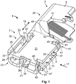
- Fig. 1
- shows a perspective illustration of a first embodiment of the flat contact socket according to the invention for a 90° connection;
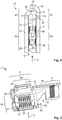
- Fig. 2
- shows a cross-section through the socket body of the flat contact socket from
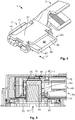
Fig. 1 ; - Fig. 3
- shows a longitudinal section through the flat contact socket from
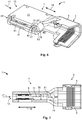
Fig. 1 with a view onto a contacting plate on the contacting section; - Fig. 4
- shows the flat contact socket from
Fig. 1 with a flat contact received in the flat contact receptacle; - Fig. 5
- shows a cut-away of a flat contact socket according to
Fig. 1 in a housing with a received flat contact; - Fig. 6
- shows a perspective illustration of a second embodiment of the flat contact socket according to the invention for a 180° connection; and
- Fig.7
- shows a longitudinal section through the flat contact socket from
Fig. 6 . - Hereinafter, the fundamental structure of a
flat contact socket 1 according to the invention for a 90° connection is described usingFig. 1 . Theflat contact socket 1 has aconnection section 3 for electrically connecting to an electrical conductor. Theconnection section 3 can in particular be a crimping section and feature at least two crimpingwings 5. Alternatively, theconnection section 3 can also be formed for otherwise connecting to an electrical conductor, in particular to a cable. - A
socket body 7 is connected to theconnection section 3. Thesocket body 7 serves substantially to connect to a flat contact (here not yet shown). For this purpose, thesocket body 7 has aflat contact receptacle 9. Theflat contact receptacle 9 extends along aflat contact plane 11, which is indicated by dotted lines inFig. 1 . - The
flat contact receptacle 9 is opened for introducing a flat contact through aninsertion opening 13. A blockingelement 15 is arranged on an end of thesocket body 7 which is opposite theinsertion opening 13, which blockingelement 15 delimits the depth of penetration for a flat contact in theflat contact receptacle 9. Theinsertion direction 17 extends from theinsertion opening 13 in the direction of the blockingelement 15. Theinsertion direction 17 runs parallel to theflat contact plane 11. Theinsertion opening 13 and the blockingelement 15 are thus opposite each other in theinsertion direction 17. - Generally, the
flat contact socket 1 extends along alongitudinal direction 19 which runs transverse to theinsertion direction 17. Theconnection section 3 and thesocket body 7 are adjoining in thelongitudinal direction 19. In the illustrated exemplary embodiment, theconnection section 3 is configured such that an electrical conductor, in particular a cable, after connecting to theconnection section 3 and by means of crimping, also initially runs substantially parallel to thelongitudinal direction 19 in the region which is directly adjacent to theflat contact socket 1. However, theflat contact socket 1 according to the invention can also have a different shape. For example, theconnection section 3 can be connected to thesocket body 7 such that theconnection section 3 extends away from it, parallel to theinsertion direction 17. Also alternatively, theconnection section 3 can extend transverse to theinsertion direction 17 and transverse to thelongitudinal direction 19, inFig. 1 this would accordingly be upwards or downwards. - The
socket body 7 has twoflat legs 21 which are opposite each other transverse to theflat contact plane 11. Thelegs 21 delimit theflat contact receptacle 9 transverse to theflat contact plane 11. Preferably, thelegs 21 are substantially continuously formed. Alternatively, they can also have openings in order to save on material, for example. On one of theends 23 of theflat contact socket 1 opposite theconnection section 3, the twolegs 21 are connected to each other by aweb 25. On one of the ends of thesocket body 7 opposite theweb 25 in thelongitudinal direction 19, the twolegs 21 are connected by thebase 27. - The base 27 runs transverse to the
insertion direction 17 or parallel to thelongitudinal direction 19 and forms a kind of backbone for theflat contact socket 1. Thebase 27 is opposite theinsertion opening 13 in theinsertion direction 17 and connects thesocket body 7 to theconnection section 3. Preferably, thebase 27 is continuously formed at least between thesocket body 7 and theconnection section 3, such that it has a good electrical conductivity. - The
flat contact socket 1 is preferably manufactured as a stamped bent part from an electricallyconductive material 28. In this case, the region of the base 27 can in particular be formed by amain bending edge 29 which runs transverse to theinsertion direction 17. The twolegs 21 are correspondingly formed by two flat regions bending towards each other around themain bending edge 29. Manufacturing by stamping and bending enables theflat contact socket 1 to be manufactured quickly and cost-efficiently. Moreover, stamping and bending also allows a particularly simple production of the blockingelement 15, which is explored hereinafter. - The blocking
element 15 is connected to acantilever 31 which extends away from the rest of thesocket body 7 in theinsertion direction 17. The blockingelement 15 protrudes from thecantilever 31, transverse to theinsertion direction 17 and transverse to thelongitudinal direction 19, i.e. transverse to theflat contact plane 11. - By arranging the blocking
element 15 on thecantilever 31, which extends in theinsertion direction 17, it is possible to receive a flat contact in theflat contact receptacle 9, which projects at least partially beyond the base 27 or beyond the rest of thesocket body 7 in theinsertion direction 17. In this way, a flat contact can be received which comprises additional elements, for example a touch protector. - The blocking
element 15 is spaced apart from the rest of theflat contact receptacle 9 by the arrangement previously described. The blockingelement 15 is preferably manufactured integrally with thesocket body 7 and particularly preferably manufactured integrally with the rest of theflat contact socket 1. This can be achieved in particular if theflat contact socket 1 is formed as a stamped bent part. The blockingelement 15 and thecantilever 31 can in this case be stamped out from thematerial 28 of theflat contact socket 1, which, without a blockingelement 15 according to the invention, would form acontinuous base 27 in the region of thesocket body 7. It can continuously transition into one of the twolegs 21, and the free end which forms the blockingelement 15 can be bent up transverse to the insertion direction and transverse to thelongitudinal direction 19. - The blocking
element 15 has twobraces 33, via which it is connected to thecantilever 31. The blockingelement 15 is therefore formed like a beam and connected to thecantilever 31 via twobraces 33 which are spaced apart. Alternatively, the region between thebraces 33 can also be closed. However,material 28 is preferably stamped out or removed there, in order to reduce the necessary bending forces for producing the shape of the blockingelement 15 or for bending up thematerial 28. - In order to effectively delimit the
flat contact receptacle 9 in theinsertion direction 17 by the blockingelement 15, the blockingelement 15 extends over half theheight 35 of theflat contact receptacle 9. Theheight 35 of theflat contact receptacle 9 is measured as the spacing between the inner faces 37 of the twolegs 21 transverse to theflat contact plane 11. - In order to prevent a flat contact from slipping out of the
flat contact receptacle 9, in particular when being introduced, theflat contact socket 1 can also feature further blocking or guide elements. In the preferred embodiment, theend 23 of theflat contact socket 1 is provided with twolateral blocking elements 39. Thelateral blocking elements 39 close theflat contact receptacle 9 in the direction of theend 23. They are preferably formed by stamping and bending frommaterial 28 of thelegs 21, wherein an approximately quadrantallateral blocking element 39 extends from eachleg 21 in the direction of theopposite leg 21. The orientation of the twolateral blocking elements 39 is thus opposing. - The
flat contact socket 1 has two latchingelements 41 for laterally guiding a flat contact upon insertion into theflat contact receptacle 9 and for fixing the position of thelegs 21 to each other. The latchingelements 41 are arranged laterally from theflat contact receptacle 9. This means that they are arranged oppositely in thelongitudinal direction 19, wherein theflat contact receptacle 9 as viewed in thelongitudinal direction 19 is arranged between them. The latchingelements 41 delimit theinsertion opening 13 laterally or in thelongitudinal direction 19. - Each of the latching
elements 41 extends from one of thelegs 21 to theopposite leg 21. Each of the latchingelements 41 has apositive engagement opening 43. This is preferably arranged at thefree end 45 of the latchingelement 41. The latchingelement 41 is formed substantially strip-shaped and can be stamped frommaterial 28 of one of the twolegs 21. - For latching, the latching
element 41 is bent in the direction of theopposite leg 21 such that thepositive engagement opening 43 is arranged on a level with theleg 21. Thisleg 21 has apositive engagement protrusion 47 which is arranged in thepositive engagement opening 43 in the connected state. In this way, a positive engagement is formed transverse to theinsertion direction 17. This prevents both the unintentional opening or compressing of the twolegs 21 from each other or towards each other, and a displacement of the twolegs 21 in thelongitudinal direction 19. - The
flat contact socket 1 has apositive engagement recess 49 which extends substantially parallel to theinsertion direction 17 into theflat contact socket 1. Thepositive engagement recess 49 extends in the direction of the base 27 from that side of theflat contact socket 1 which is opposite thebase 27, against theinsertion direction 17. - The positive engagement recess extends substantially between the
socket body 7 and theconnection section 3. Thepositive engagement recess 49 can serve to receive a substantially complementary formed positive engagement element of a housing (not illustrated). By virtue of the fact that thebase 27 is continuously formed on the side which is opposite the positive engagement recess, theflat contact socket 1 can preferably only be inserted into the housing if the positive engagement element of the housing is arranged in thepositive engagement recess 49. By attempting to insert theflat contact socket 1 in another orientation into the housing, thebase 27 can abut against the positive engagement element, for example, such that the insertion into the housing or a closing of a housing is prevented. This function is explored subsequently with reference toFig. 5 . - The
positive engagement recess 49 extends so far in the direction of the base 27 into the material of theflat contact socket 1 that the crimpingwings 5 of theconnection section 3 are shaped by thepositive engagement recess 49 or by anelongation 51 of thepositive engagement recess 49. - Preferably, a
stop surface 53 is formed on thesocket body 7 by thepositive engagement recess 49, which stopsurface 53 runs parallel to theinsertion direction 17. If theflat contact socket 1 is arranged in a housing and if a positive engagement element of the housing is located against thestop surface 53, theflat contact socket 1 being pulled out of the housing under a tensile force acting in the direction of theconnection section 3 can be effectively prevented by a positive engagement of thestop surface 53 with the positive engagement element. -
Fig. 2 shows some elements of theflat contact socket 1 in an enlarged representation and in a cross-section through thesocket body 7 transverse to thelongitudinal direction 19. -
Fig. 2 shows that the blockingelement 15 extends over half theheight 35 in the direction of anopposing leg 21. It thus effectively prevents the introduction of a flat contact into theflat contact receptacle 9 beyond the blockingelement 15. The blockingelement 15 is downstream of the rest of thesocket body 7 in theinsertion direction 17. Thelateral blocking elements 39 close theflat contact receptacle 9 effectively transverse to theinsertion direction 17. - Further details of the
flat contact socket 1, which are not described with reference toFig. 1 or are not illustrated or to be seen inFig. 1 , are described hereinafter with reference toFigs. 2 and 3 . - The
legs 21 have contactingsections 55. The contactingsections 55 serve to electrically contact a flat contact arranged in theflat contact receptacle 9. The contactingsections 55 are arranged on the inner faces 37 of thelegs 21. It is also possible that only one of the twolegs 21 has a contactingsection 55 for electrical contacting. Alternatively, one of thelegs 21 can also be provided with a press-on organ, for example, which is formed to mechanically fix a flat contact in theflat contact receptacle 9. - In order to improve the electrical connection between the
flat contact socket 1 and a flat contact, each contactingsection 55 has several contact springs 57, which project into theflat contact receptacle 9 and are resiliently deflectable towards therespective leg 21. Each of the inner faces 37 in the contactingsection 55 preferably has a contactingplate 59 which is provided with a plurality of contact springs 57. The contactingplates 59 are electrically conductively connected to therespective legs 21. The contactingplates 59 are preferably welded to the inner faces 37 of thelegs 21. - The two contacting
plates 59 are opposite each other across theflat contact receptacle 9. The contactingplates 59 or the contactingsections 55 are preferably spaced apart from the blockingelement 15 against theinsertion direction 17. Thefree space 61, which extends between the contactingsections 55 and the blockingelement 15, can serve to receive a touch protector for example, which can be arranged around an electrically conductive part of a flat contact. This is described hereinafter with reference toFig. 4 . -
Fig. 4 shows aflat contact socket 1 of the kind previously described with a part of aflat contact 63 arranged in theflat contact receptacle 9. Theflat contact 63 can have an electricallyconductive part 65. The electricallyconductive part 65 is preferably surrounded by atouch protector 67. Contactingsurfaces 69 of the electrically conductive part of theflat contact 63 are exposed. - In the inserted state, the
flat contact 63 abuts against the blockingelement 15 with afront end 71 of thetouch protector 67. Thefront end 71 of thetouch protector 67 is arranged in thefree space 61. At the same time, the contactingsurfaces 69 can be located against the two contactingsections 55 of theflat contact socket 1 such that an electrical connection is established. - Hereinafter, a
flat contact socket 1 according to the invention of the kind previously described is described in a housing with reference toFig. 5. Fig. 5 illustrates theflat contact socket 1 with aflat contact 63 arranged in theflat contact receptacle 9. - The
flat contact socket 1 is arranged in a two-part housing 73. Thehousing 73 includes anupper part 75 and alower part 77. The twoparts Fig. 5 . - The
housing 73 includes anopening 79 through which aflat contact 63 can enter into the interior of thehousing 73 and thus into theflat contact receptacle 9 of theflat contact socket 1. Preferably, thehousing 73 has at least one further opening (not shown) through which an electrical conductor can be connected to theconnection section 3 of theflat contact socket 1. - The
housing 73 has on the lower part 77 apositive engagement element 81 which protrudes into an interior of thehousing 73. In the assembled state shown inFig. 5 , thepositive engagement element 81 is arranged in thepositive engagement recess 49 of theflat contact socket 1 and is located against thestop surface 53. Theflat contact socket 1 is thereby positively secured against being pulled out of thehousing 73 in the direction of theconnection section 3. The interplay between thepositive engagement element 81 and thepositive engagement recess 49 also serves to avoid faults when assembling thehousing parts flat contact socket 1 into thehousing 73. If, for example, theflat contact socket 1 was inserted into thelower part 77 such that thebase 27 was located against thepositive engagement element 81, theupper part 75 could no longer be moved towards thelower part 77 such that the two parts could be connected. - The
upper part 75 has a pressing element 83 which is arranged opposite thepositive engagement element 81 against theinsertion direction 17. In the assembled state, the pressing element 83 presses on thebase 27 of theflat contact socket 1 such that it is held securely in theinsertion direction 17. Moreover, theupper part 75 of the housing can have one ormore protrusions 85, which press against the blockingelement 15 of theflat contact socket 1 in the assembled state, in order to ensure a secure fitting of theflat contact socket 1 in thehousing 73 in the region of the blockingelement 15 too. Furthermore, vibrations or oscillations of the blockingelement 15 can thus be reduced. In an alternative configuration, for each of theprotrusions 85 the blockingelement 15 can have a depression or groove into which theprotrusion 85 can enter such that an additional positive engagement can also be obtained therein, transverse to theinsertion direction 17. - The structure of a second advantageous embodiment of the
flat contact socket 1 according to the invention is described hereinafter with reference toFigs. 6 and 7 . For the sake of brevity, only the differences from the embodiments which are described with reference toFigs. 1 to 5 are explored. - The second embodiment can be used for a 180° connection. This means that the
socket body 7 and theconnection section 3 are arranged relative to each other such that an electrical conductor runs substantially parallel to theinsertion direction 17, at least in theconnection section 3. - Consequently, the
insertion direction 17 runs parallel to thelongitudinal direction 19. Theinsertion opening 13 is therefore arranged on the end of thesocket body 7 located in thelongitudinal direction 19 and not on the side thereof. - The blocking
element 15 extends from one of thelegs 21 in theinsertion direction 17 and therefore substantially in the direction of theconnection section 3. Thecantilever 31, which extends in theinsertion direction 17, and the blockingelement 15, which protrudes transverse to theinsertion direction 17, thus merge into each other. The blockingelement 15 and thecantilever 31 can be formed as a bent tongue 87, theend section 89 thereof being formed by the blockingelement 15. As with the previously described embodiment, the blockingelement 15 extends transverse to theflat contact plane 11 over half theheight 35 of theflat contact receptacle 9. - As with the first embodiment of the
flat contact socket 1 according to the invention, here too the twolegs 21 are connected to each other by latchingelements 41. However, in the second embodiment, in the region between the two latchingelements 41, a blockingweb 91 extends which prevents an unintentional insertion of a flat contact transverse to theinsertion direction 17, i.e. between the two latchingelements 41. - The
cantilever 31 extends from the latchingelement 41 which is located nearer to theconnection section 3. This means that thecantilever 31 extends from the part of theleg 21 which is provided with thepositive engagement protrusion 47 of this latchingelement 41. Consequently, what follows from the arrangement is that thecantilever 31 and thepositive engagement protrusion 47 run substantially perpendicular to each other. - The arrangement of the blocking
element 15 in the second embodiment does not rule out the presence of apositive engagement recess 49 with astop surface 53 which runs transverse to thelongitudinal direction 19. In the second embodiment, thepositive engagement recess 49 does not extend through theflat contact socket 1 continuously transverse to theflat contact receptacle 11. Instead, thestop surface 53 is arranged on theleg 21 which is opposite the blockingelement 15. Thepositive engagement recess 49 extends between thisstop surface 53 and the two crimpingwings 5 of theconnection section 3. -
- 1
- Flat contact socket
- 3
- Connection section
- 5
- Crimping wing
- 7
- Socket body
- 9
- Flat contact receptacle
- 11
- Flat contact plane
- 13
- Insertion opening
- 15
- Blocking element
- 17
- Insertion direction
- 19
- Longitudinal direction
- 21
- Legs
- 23
- End of the flat contact socket
- 25
- Web
- 27
- Base
- 28
- Electrically conductive material
- 29
- Main bending edge
- 31
- Cantilever
- 33
- Braces
- 35
- Height of the flat contact receptacle
- 37
- Inner faces of the legs
- 39
- Lateral blocking elements
- 41
- Latching elements
- 43
- Positive engagement opening
- 45
- Free end of a latching element
- 47
- Positive engagement protrusion
- 49
- Positive engagement recess
- 51
- Extension of the positive engagement recess
- 53
- Stop surface
- 55
- Contacting section
- 57
- Contact spring
- 59
- Contacting plate
- 61
- Free space
- 63
- Flat contact
- 65
- Electrically conductive part of the flat contact
- 67
- Touch protector
- 69
- Contact surface
- 71
- Front end of the flat contact
- 73
- Housing
- 75
- Upper part of the housing
- 77
- Lower part of the housing
- 79
- Opening for flat contact
- 81
- Positive engagement element
- 83
- Pressing element
- 85
- Protrusion
- 87
- Tongue
- 89
- End section of the tongue
- 91
- Blocking web
Claims (15)
- A flat contact socket (1) with a connection section (3) for electrically connecting to an electrical conductor and to a flat contact receptacle (9), which extends in a socket body (7) along a flat contact plane (11), which is spaced apart from the connection section (3), and into which a flat contact (63) can be inserted through an insertion opening (13) along an insertion direction (17), wherein the flat contact socket (1) has at least one blocking element (15) which is opposite the insertion opening (13) in the insertion direction (17) and which delimits the flat contact receptacle (9) at least in the insertion direction (17), characterised in that the at least one blocking element (15) protrudes transverse to the insertion direction (17) from at least one cantilever (31) which extends in the insertion direction (17).
- The flat contact socket (1) according to Claim 1, characterised in that the at least one blocking element (15) is formed integrally with the rest of the flat contact socket (1).
- The flat contact socket (1) according to Claim 1 or 2, characterised in that the at least one blocking element (15) has at least one brace (33) via which it is connected to the cantilever (31).
- The flat contact socket (1) according to any one of Claims 1 to 3, characterised in that the at least one blocking element (15) extends up to at least half the height (35) of the flat contact receptacle (9) measured transverse to the flat contact plane (11).
- The flat contact socket (1) according to any one of Claims 1 to 4, characterised in that the socket body (7) has at least two legs (21) which are opposite each other transverse to the flat contact plane (11), and by means of which the flat contact receptacle (9) is delimited transverse to the flat contact plane (11).
- The flat contact socket (1) according to Claim 5, characterised in that the at least two legs (21) are connected via at least one web (25) which is opposite the insertion opening (13) in the insertion direction (17).
- The flat contact socket (1) according to Claim 5 or 6, characterised in that at least one of the legs (21) has at least one contacting section (55) on an inner face of the leg (37) for electrical contacting with the flat contact (63).
- The flat contact socket (1) according to Claim 7, characterised in that the at least one contacting section (55) is provided with at least one contact spring (57) which projects into the flat contact receptacle (9) and is resiliently deflectable towards the leg (21).
- The flat contact socket (1) according to any one of Claims 5 to 8, characterised in that the flat contact socket (1) has a base (27) which runs transverse to the insertion direction (17), which is opposite the insertion opening (13) in the insertion direction (17), and by means of which the socket body (7) is connected to the connection section (3).
- The flat contact socket (1) according to any one of Claims 1 to 9, characterised in that the connection section (3) has at least two crimping wings (5) for connecting to an electrical conductor by means of crimping.
- The flat contact socket (1) according to any one of Claims 1 to 10, characterised in that the flat contact socket (1) has at least one positive engagement recess (49), which extends substantially parallel to the insertion direction (17) into the flat contact socket (1), for producing a positive engagement with a housing (73).
- The flat contact socket (1) according to Claim 11, characterised in that at least one stop surface (53), which runs parallel to the insertion direction (17), is formed by the at least one positive engagement recess (49) on the socket body (7), for securing the flat contact socket (1) in a housing (73).
- The flat contact socket (1) according to any one of Claims 1 to 12, characterised in that the flat contact socket (1) is manufactured as a stamped bent part.
- The flat contact socket (1) according to Claim 13, characterised in that the base (27) is formed by a main bending edge (29) which runs transverse or longitudinal to the insertion direction (17).
- The flat contact socket (1) according to Claim 14, characterised in that the at least one blocking element (15) is at least partially stamped out from material (28) of the main bending edge (29) and is downstream of it in the insertion direction (17).
Applications Claiming Priority (1)
| Application Number | Priority Date | Filing Date | Title |
|---|---|---|---|
| DE102016221351.2A DE102016221351A1 (en) | 2016-10-28 | 2016-10-28 | Flat contact socket with extension arm |
Publications (2)
| Publication Number | Publication Date |
|---|---|
| EP3316403A1 true EP3316403A1 (en) | 2018-05-02 |
| EP3316403B1 EP3316403B1 (en) | 2019-11-20 |
Family
ID=57890656
Family Applications (2)
| Application Number | Title | Priority Date | Filing Date |
|---|---|---|---|
| EP17151499.5A Active EP3316402B1 (en) | 2016-10-28 | 2017-01-13 | Flat contact bushing |
| EP17198732.4A Active EP3316403B1 (en) | 2016-10-28 | 2017-10-27 | Flat contact bushing |
Family Applications Before (1)
| Application Number | Title | Priority Date | Filing Date |
|---|---|---|---|
| EP17151499.5A Active EP3316402B1 (en) | 2016-10-28 | 2017-01-13 | Flat contact bushing |
Country Status (5)
| Country | Link |
|---|---|
| US (2) | US10236612B2 (en) |
| EP (2) | EP3316402B1 (en) |
| JP (2) | JP7004542B2 (en) |
| CN (2) | CN108011247B (en) |
| DE (1) | DE102016221351A1 (en) |
Families Citing this family (20)
| Publication number | Priority date | Publication date | Assignee | Title |
|---|---|---|---|---|
| JP6787175B2 (en) * | 2017-02-22 | 2020-11-18 | 株式会社オートネットワーク技術研究所 | Multi-contact terminal |
| KR102312421B1 (en) * | 2018-06-22 | 2021-10-12 | 주식회사 엘지에너지솔루션 | Terminal for connector and connector including the same |
| DE102018119844B4 (en) * | 2018-07-26 | 2022-10-06 | Auto-Kabel Management Gmbh | Electrical connection and method of making an electrical connection |
| CN110265815A (en) * | 2019-06-21 | 2019-09-20 | 陈丽霞 | A kind of elbow connector jack |
| US11515678B2 (en) | 2020-01-09 | 2022-11-29 | Aptiv Technologies Limited | Splice connector |
| US11387585B2 (en) * | 2020-08-05 | 2022-07-12 | Aptiv Technologies Limited | Anti-fretting/multiple contact terminal using knurl pattern |
| US11264735B1 (en) * | 2020-08-28 | 2022-03-01 | TE Connectivity Services Gmbh | Electrical terminal for terminating a wide size range of magnet wires |
| WO2022076233A1 (en) * | 2020-10-08 | 2022-04-14 | Interplex Industries, Inc. | Bus bar connector |
| CN112038805A (en) * | 2020-10-13 | 2020-12-04 | 陈丽霞 | Elbow straight connector jack |
| JP7444043B2 (en) * | 2020-12-16 | 2024-03-06 | 株式会社オートネットワーク技術研究所 | terminal unit |
| CN112751228A (en) * | 2020-12-30 | 2021-05-04 | 泰科电子(上海)有限公司 | Terminal body for high-voltage connection, cable assembly and connector |
| CN214797803U (en) | 2020-12-30 | 2021-11-19 | 泰科电子(上海)有限公司 | Terminal body, connecting terminal and sheet stock for manufacturing terminal body |
| CN115224514A (en) * | 2021-04-14 | 2022-10-21 | 泰科电子(上海)有限公司 | Electrical connection terminal and electrical connection assembly |
| US11646510B2 (en) | 2021-04-29 | 2023-05-09 | Aptiv Technologies Limited | Shielding electrical terminal with knurling on inner contact walls |
| CN113258352B (en) | 2021-05-26 | 2022-11-29 | 宣城立讯精密工业有限公司 | Electric connection kit and electric connector |
| CN113258372B (en) | 2021-05-26 | 2022-12-02 | 宣城立讯精密工业有限公司 | Electrical connection kit and electrical connector |
| JP7608288B2 (en) * | 2021-07-29 | 2025-01-06 | 古河電気工業株式会社 | Female terminals, connectors, electric wires with terminals, electric wires with connectors, and wire harnesses |
| JP7740927B2 (en) * | 2021-07-29 | 2025-09-17 | 古河電気工業株式会社 | Female terminals, connectors, wires with terminals, wires with connectors, and wire harnesses |
| JP2024032406A (en) * | 2022-08-29 | 2024-03-12 | 古河電気工業株式会社 | Connection terminals, connectors, electric wires with terminals, and wire harnesses |
| EP4407808A1 (en) * | 2023-01-24 | 2024-07-31 | Tyco Electronics France SAS | Socket, socket connector, contact element and connection assembly |
Citations (4)
| Publication number | Priority date | Publication date | Assignee | Title |
|---|---|---|---|---|
| WO2005096448A1 (en) * | 2004-03-30 | 2005-10-13 | Kostal Kontakt Systeme Gmbh | Electrical socket contact for high current applications |
| DE202007000302U1 (en) * | 2007-01-09 | 2007-05-16 | Sorig, Ludger | Electrical plugging socket contact for high current application, has base plate provided in U-shaped curved contact area and connection area, and current bus bar and s-shaped end area that are connected with connection area |
| WO2010057096A1 (en) * | 2008-11-17 | 2010-05-20 | J.S.T. Corporation | Female terminal assembly |
| EP2899813A1 (en) * | 2014-01-28 | 2015-07-29 | Omron Corporation | Connector |
Family Cites Families (94)
| Publication number | Priority date | Publication date | Assignee | Title |
|---|---|---|---|---|
| NL124818C (en) * | 1960-05-26 | |||
| GB1463751A (en) * | 1974-05-03 | 1977-02-09 | Amp Inc | Electrical tab receptacle |
| FR2478383A1 (en) * | 1980-03-11 | 1981-09-18 | Amp France | ELECTRICAL CONTACT MEMBER FOR CONNECTING WITH A MALE CONTACT MEMBER, AND ELECTRICAL CONNECTOR COMPRISING SUCH A CONTACT MEMBER |
| US4679887A (en) * | 1982-03-24 | 1987-07-14 | Amp Incorporated | Electrical terminal |
| US4421375A (en) * | 1982-03-29 | 1983-12-20 | Amp Incorporated | Flag-type terminal having insulation displacement wire connection |
| NL8202668A (en) * | 1982-07-02 | 1984-02-01 | Philips Nv | ELECTRIC CONTACT. |
| US4534613A (en) * | 1983-10-31 | 1985-08-13 | Amp Incorporated | Receptacle terminal having locking lance |
| FR2559624B1 (en) * | 1984-02-14 | 1986-05-23 | Labinal | ELECTRIC CONTACT MEMBER |
| FR2589637B1 (en) * | 1985-11-05 | 1987-12-11 | Labinal | FEMALE ELEMENT OF ELECTRICAL CONTACTS |
| US4685754A (en) * | 1985-12-13 | 1987-08-11 | Amp Incorporated | Electrical tab receptacle |
| GB8700870D0 (en) * | 1987-01-15 | 1987-02-18 | Amp Italia | Electrical tabreceptacle |
| FR2693041B1 (en) * | 1992-06-26 | 1996-04-05 | Proner Comatel Sa | ELECTRICAL CONNECTION DEVICE BY CLIP AND TONGUE. |
| US5525070A (en) * | 1994-04-15 | 1996-06-11 | Panduit Corp. | Positive lock insulated disconnect |
| DE9416056U1 (en) * | 1994-10-06 | 1994-11-24 | Stocko Metallwarenfabriken Henkels Und Sohn Gmbh & Co, 42327 Wuppertal | Lockable blade receptacle for an electrical connection |
| US5588884A (en) * | 1995-09-08 | 1996-12-31 | Packard Hughes Interconnect Company | Stamped and formed contacts for a power connector |
| US5800220A (en) * | 1995-10-23 | 1998-09-01 | Framatome Connectors Interlock Inc. | Tab receptacle terminal |
| US6039615A (en) * | 1996-03-15 | 2000-03-21 | The Whitaker Corporation | Female electrical terminal having overstress members |
| US5911605A (en) * | 1997-10-16 | 1999-06-15 | Ui Automotive Dearborn, Inc. | Universal terminal connection |
| JP2000173703A (en) * | 1998-12-08 | 2000-06-23 | Yazaki Corp | Electrical contacts |
| US6416340B2 (en) * | 2000-05-04 | 2002-07-09 | Christopher E. Schaefer | Single blade terminal power connector system |
| GB0016790D0 (en) * | 2000-07-07 | 2000-08-30 | Tyco Electronics Amp Es Sa | Electrical connector |
| US6276960B1 (en) * | 2000-08-29 | 2001-08-21 | Delphi Technologies, Inc. | Electrical power connector system |
| US6485337B2 (en) * | 2000-08-30 | 2002-11-26 | Delphi Technologies, Inc. | Electrical connector |
| US6287156B1 (en) * | 2000-08-31 | 2001-09-11 | Lear Corporation | Electrical terminal connector |
| US6672911B2 (en) * | 2000-09-15 | 2004-01-06 | Alcoa Fujikura Limited | Electrical terminal socket assembly including 90 angled and sealed connectors |
| FR2817401B1 (en) * | 2000-11-30 | 2003-01-10 | Proner Comatel Sa | FEMALE ELEMENT FOR ELECTRICAL CONNECTION |
| US20030060090A1 (en) * | 2001-09-21 | 2003-03-27 | Allgood Christopher L. | High current automotive electrical connector and terminal |
| US6692316B2 (en) * | 2002-04-16 | 2004-02-17 | Delphi Technologies, Inc. | High current terminal blade type sealed connection system |
| DE10351540B3 (en) * | 2003-11-03 | 2005-08-11 | Intedis Gmbh & Co. Kg | Flat plug socket |
| DE102005017988B3 (en) * | 2005-04-19 | 2006-11-16 | Tyco Electronics Amp Gmbh | Electric contact sleeve has band bent to close off inner space of contact sleeve |
| JP4607749B2 (en) * | 2005-12-06 | 2011-01-05 | トヨタ自動車株式会社 | Female connector terminal and female connector |
| DE102006009074B4 (en) * | 2006-02-28 | 2016-02-25 | Robert Bosch Gmbh | Electrical connector with prestressed contact lamella |
| JP2008140589A (en) * | 2006-11-30 | 2008-06-19 | Yazaki Corp | Female terminal |
| DE102007016070A1 (en) * | 2007-04-03 | 2008-10-09 | Lear Corp., Southfield | Electrical connection arrangement and method for using the electrical connection arrangement |
| JP4488372B2 (en) | 2007-08-03 | 2010-06-23 | ヒロセ電機株式会社 | Electrical connector for cable |
| CN101816103B (en) * | 2007-10-02 | 2013-06-19 | 奥斯兰姆有限公司 | Plug device, plug connector, and method for producing the plug connector |
| KR101006881B1 (en) * | 2007-12-14 | 2011-01-12 | 주식회사 엘지화학 | Improved fastening structure PCM and battery pack containing the same |
| DE102008017043B3 (en) * | 2008-04-03 | 2009-09-03 | Lear Corp., Southfield | Electrical bushing contact producing method for receiving plug contact for electrical connection in motor vehicle environment, involves folding contact arm such that arm forms elastic spring, which contacts plug contact |
| US20100029146A1 (en) * | 2008-08-04 | 2010-02-04 | Tyco Electronics Corporation | Socket contact |
| JP5185022B2 (en) * | 2008-08-27 | 2013-04-17 | イリソ電子工業株式会社 | Electrical contact and connector using the same |
| EP2211425A1 (en) * | 2009-01-23 | 2010-07-28 | MTA S.p.A. | Female electrical terminal |
| JP5643753B2 (en) * | 2009-05-20 | 2014-12-17 | 行田電線株式会社 | Connection terminal, terminal connection structure, and terminal box |
| US7892050B2 (en) * | 2009-06-17 | 2011-02-22 | Lear Corporation | High power fuse terminal with scalability |
| US8366497B2 (en) * | 2009-06-17 | 2013-02-05 | Lear Corporation | Power terminal |
| US8668531B2 (en) * | 2009-07-03 | 2014-03-11 | Yazaki Corporation | Terminal |
| JP5381492B2 (en) * | 2009-08-19 | 2014-01-08 | 住友電装株式会社 | Female terminal bracket |
| KR101598633B1 (en) * | 2009-11-11 | 2016-02-29 | 타이코에이엠피 주식회사 | Terminal for connector |
| DE102010002176B4 (en) * | 2010-02-22 | 2011-12-15 | Tyco Electronics Amp Gmbh | contactor |
| JP5447971B2 (en) * | 2010-04-08 | 2014-03-19 | 住友電装株式会社 | Terminal bracket connection structure |
| US8057261B1 (en) * | 2010-11-02 | 2011-11-15 | Etco, Inc. | Flag terminal insulator |
| DE102011011151B4 (en) * | 2010-11-24 | 2014-12-04 | Lear Corporation | Connection socket arrangement for an electrical plug connection |
| US8419486B2 (en) * | 2010-12-17 | 2013-04-16 | Tyco Electronics Corporation | Receptacle terminal with a contact spring |
| DE202011003555U1 (en) * | 2011-03-04 | 2011-05-26 | ROSENBERGER Hochfrequenztechnik GmbH & Co. KG, 83413 | High current connector with ring spring contact |
| JP5083847B1 (en) * | 2011-06-07 | 2012-11-28 | 日本航空電子工業株式会社 | Contact elements and connectors |
| JP5723695B2 (en) * | 2011-06-21 | 2015-05-27 | 矢崎総業株式会社 | Female terminal |
| KR101342507B1 (en) * | 2011-09-02 | 2013-12-17 | 삼성에스디아이 주식회사 | rechargeable battery pack |
| JP6055173B2 (en) * | 2011-09-27 | 2016-12-27 | 矢崎総業株式会社 | Female terminal |
| DE102011085700A1 (en) * | 2011-11-03 | 2013-05-08 | Bayerische Motoren Werke Aktiengesellschaft | High current connectors for automotive applications |
| JP5872970B2 (en) * | 2012-06-13 | 2016-03-01 | 矢崎総業株式会社 | Connector terminal and connection structure between this connector terminal and mating terminal |
| DE102013013633A1 (en) * | 2012-09-24 | 2014-04-10 | Lear Corp. | Electrical terminal for use in high current applications, has spring head that is in contact with arms toward distal end of contact portion for applying force in direction toward central axis of contact portion |
| US8998655B2 (en) * | 2012-09-24 | 2015-04-07 | Lear Corporation | Electrical terminal |
| US9065192B2 (en) * | 2013-09-19 | 2015-06-23 | Tyco Electronics Corporation | Power terminal connector |
| DE102014001692A1 (en) * | 2013-02-08 | 2014-08-14 | Lear Corporation | Socket electrical connection subunit for completing electric circuits in energy distribution box, in motor car, has clamp attached at connector base, for applying force to pre-tension pins into channel for maintaining gap between pins |
| US9166322B2 (en) * | 2013-02-08 | 2015-10-20 | Lear Corporation | Female electric terminal with gap between terminal beams |
| US9379470B2 (en) * | 2013-02-18 | 2016-06-28 | Lear Corporation | Female electrical connector with terminal arm extension protection |
| US9548553B2 (en) * | 2013-03-15 | 2017-01-17 | Lear Corporation | Terminal with front end protection |
| US9153889B2 (en) * | 2013-04-09 | 2015-10-06 | Delphi Technologies, Inc. | Electrical connector system connectable in a straight or right angle configuration |
| US8992258B2 (en) * | 2013-04-26 | 2015-03-31 | Delphi Technologies, Inc. | Electrical cable connector shield with positive retention locking feature |
| JP6389598B2 (en) * | 2013-07-05 | 2018-09-12 | 矢崎総業株式会社 | Female terminal assembly |
| US9190756B2 (en) * | 2013-08-01 | 2015-11-17 | Lear Corporation | Electrical terminal assembly |
| WO2015037808A1 (en) * | 2013-09-12 | 2015-03-19 | 조인셋 주식회사 | Solderable electrical connector |
| DE102014113490A1 (en) * | 2013-09-18 | 2015-03-19 | Hirschmann Automotive Gmbh | Contact element for a connector |
| CN203456624U (en) * | 2013-09-27 | 2014-02-26 | 泰科电子(上海)有限公司 | Connection terminal |
| JP2015076199A (en) * | 2013-10-07 | 2015-04-20 | 矢崎総業株式会社 | Female terminal fitting |
| TWI513129B (en) * | 2014-03-07 | 2015-12-11 | Japan Aviation Electron | Connector assembly |
| DE102014005536B4 (en) * | 2014-04-16 | 2016-04-07 | Lisa Dräxlmaier GmbH | Contact blade for forming a socket by coupling with a housing element and a socket, formed by coupling the contact blade with a housing element |
| JP6014075B2 (en) * | 2014-04-17 | 2016-10-25 | ヒロセ電機株式会社 | Electrical connector assembly |
| JP5747102B1 (en) * | 2014-04-18 | 2015-07-08 | 日本航空電子工業株式会社 | Female contact and power connector |
| CN104037523B (en) * | 2014-06-13 | 2016-05-11 | 四川永贵科技有限公司 | A kind of large current terminal |
| JP6591146B2 (en) * | 2014-07-08 | 2019-10-16 | 日本航空電子工業株式会社 | Contact and connector including the same |
| EP3051635B1 (en) * | 2015-01-30 | 2018-01-17 | TE Connectivity Germany GmbH | Electric contact means and electrical cable assembly for the automotive industry |
| DE102015201694A1 (en) * | 2015-01-30 | 2016-08-04 | Te Connectivity Germany Gmbh | Electrical contact device |
| DE102015104377B4 (en) * | 2015-03-24 | 2020-04-02 | Lisa Dräxlmaier GmbH | Contact part and method for producing a contact part |
| CN105098395B (en) * | 2015-07-16 | 2017-12-12 | 凡甲电子(苏州)有限公司 | Electric connector and its terminal assemblies |
| DE102015216632A1 (en) * | 2015-08-31 | 2017-03-02 | Te Connectivity Germany Gmbh | Arrangement for establishing an electrical connection between a flat contact and a high-current conductor |
| DE102015119723A1 (en) * | 2015-11-16 | 2017-05-18 | Te Connectivity Germany Gmbh | Contactor detent spring, electrical contactor assembly, and electrical connector |
| US9537245B1 (en) * | 2015-11-18 | 2017-01-03 | Eaton Corporation | Meter center, and socket assembly and method of assembling a socket assembly therefor |
| DE102016201103B4 (en) * | 2016-01-26 | 2023-10-05 | Lisa Dräxlmaier GmbH | Contact part |
| CN107134674B (en) * | 2016-02-29 | 2021-04-27 | 泰科电子(上海)有限公司 | Conductive connectors and connecting components |
| JP6619287B2 (en) * | 2016-04-14 | 2019-12-11 | 日本航空電子工業株式会社 | Connector terminal |
| JP6591341B2 (en) * | 2016-04-21 | 2019-10-16 | 日本航空電子工業株式会社 | Connector terminal |
| DE102016209478A1 (en) * | 2016-05-31 | 2017-11-30 | Te Connectivity Germany Gmbh | Connecting cage for connecting two electrical flat contacts |
| US10784595B2 (en) * | 2016-08-01 | 2020-09-22 | Te Connectivity Corporation | Power terminal for an electrical connector |
| US9692163B1 (en) * | 2016-08-30 | 2017-06-27 | Te Connectivity Corporation | Crush rib housing for postive lock receptacle |
-
2016
- 2016-10-28 DE DE102016221351.2A patent/DE102016221351A1/en not_active Ceased
-
2017
- 2017-01-13 EP EP17151499.5A patent/EP3316402B1/en active Active
- 2017-10-25 JP JP2017205727A patent/JP7004542B2/en active Active
- 2017-10-25 JP JP2017205751A patent/JP7051370B2/en active Active
- 2017-10-27 US US15/795,388 patent/US10236612B2/en active Active
- 2017-10-27 US US15/795,461 patent/US10256560B2/en active Active
- 2017-10-27 EP EP17198732.4A patent/EP3316403B1/en active Active
- 2017-10-30 CN CN201711035648.2A patent/CN108011247B/en active Active
- 2017-10-30 CN CN201711035647.8A patent/CN108011219B/en active Active
Patent Citations (4)
| Publication number | Priority date | Publication date | Assignee | Title |
|---|---|---|---|---|
| WO2005096448A1 (en) * | 2004-03-30 | 2005-10-13 | Kostal Kontakt Systeme Gmbh | Electrical socket contact for high current applications |
| DE202007000302U1 (en) * | 2007-01-09 | 2007-05-16 | Sorig, Ludger | Electrical plugging socket contact for high current application, has base plate provided in U-shaped curved contact area and connection area, and current bus bar and s-shaped end area that are connected with connection area |
| WO2010057096A1 (en) * | 2008-11-17 | 2010-05-20 | J.S.T. Corporation | Female terminal assembly |
| EP2899813A1 (en) * | 2014-01-28 | 2015-07-29 | Omron Corporation | Connector |
Also Published As
| Publication number | Publication date |
|---|---|
| US10236612B2 (en) | 2019-03-19 |
| DE102016221351A1 (en) | 2018-05-03 |
| EP3316402A1 (en) | 2018-05-02 |
| JP2018073826A (en) | 2018-05-10 |
| JP7004542B2 (en) | 2022-01-21 |
| EP3316402B1 (en) | 2020-04-08 |
| US20180123276A1 (en) | 2018-05-03 |
| CN108011247A (en) | 2018-05-08 |
| US20180123275A1 (en) | 2018-05-03 |
| CN108011219A (en) | 2018-05-08 |
| US10256560B2 (en) | 2019-04-09 |
| EP3316403B1 (en) | 2019-11-20 |
| JP2018073827A (en) | 2018-05-10 |
| CN108011219B (en) | 2021-06-25 |
| CN108011247B (en) | 2021-03-30 |
| JP7051370B2 (en) | 2022-04-11 |
Similar Documents
| Publication | Publication Date | Title |
|---|---|---|
| EP3316403B1 (en) | Flat contact bushing | |
| US9847604B2 (en) | Electrical connector having improved shielding structure | |
| JP5563241B2 (en) | Electrical connector | |
| US10505288B2 (en) | Electrical connector having terminal supports | |
| US9601854B2 (en) | Female terminal | |
| KR101208447B1 (en) | Connection terminal | |
| US8821197B2 (en) | Fuse terminal | |
| CN104253337A (en) | Connector, and header and socket included in the same | |
| KR20170024112A (en) | Female terminal and electrical connector | |
| KR102425767B1 (en) | A contact blade for a socket-shaped connector part, and a socket-shaped connector part | |
| US11158972B2 (en) | Socket connector assembly | |
| KR20100121950A (en) | Connector having joint terminal | |
| KR101654573B1 (en) | connector | |
| US20240072457A1 (en) | Terminal | |
| JP3682824B2 (en) | connector | |
| JP5388350B2 (en) | Electrical connection terminal and connector using the same | |
| KR100988794B1 (en) | Connector | |
| KR20220019482A (en) | Connector and connector assembly | |
| EP3324488B1 (en) | Connector arrangement with a conductor press-on member | |
| KR100976510B1 (en) | Vertical Terminals and Connectors with the Same | |
| JP4076314B2 (en) | Electrical connector with fixing bracket | |
| KR101520927B1 (en) | Terminal | |
| KR200466960Y1 (en) | connector | |
| SG181185A1 (en) | Electrical connector | |
| JP2016018716A (en) | Wire holding structure |
Legal Events
| Date | Code | Title | Description |
|---|---|---|---|
| PUAI | Public reference made under article 153(3) epc to a published international application that has entered the european phase |
Free format text: ORIGINAL CODE: 0009012 |
|
| STAA | Information on the status of an ep patent application or granted ep patent |
Free format text: STATUS: THE APPLICATION HAS BEEN PUBLISHED |
|
| AK | Designated contracting states |
Kind code of ref document: A1 Designated state(s): AL AT BE BG CH CY CZ DE DK EE ES FI FR GB GR HR HU IE IS IT LI LT LU LV MC MK MT NL NO PL PT RO RS SE SI SK SM TR |
|
| AX | Request for extension of the european patent |
Extension state: BA ME |
|
| STAA | Information on the status of an ep patent application or granted ep patent |
Free format text: STATUS: REQUEST FOR EXAMINATION WAS MADE |
|
| 17P | Request for examination filed |
Effective date: 20181023 |
|
| RBV | Designated contracting states (corrected) |
Designated state(s): AL AT BE BG CH CY CZ DE DK EE ES FI FR GB GR HR HU IE IS IT LI LT LU LV MC MK MT NL NO PL PT RO RS SE SI SK SM TR |
|
| GRAP | Despatch of communication of intention to grant a patent |
Free format text: ORIGINAL CODE: EPIDOSNIGR1 |
|
| STAA | Information on the status of an ep patent application or granted ep patent |
Free format text: STATUS: GRANT OF PATENT IS INTENDED |
|
| GRAJ | Information related to disapproval of communication of intention to grant by the applicant or resumption of examination proceedings by the epo deleted |
Free format text: ORIGINAL CODE: EPIDOSDIGR1 |
|
| GRAP | Despatch of communication of intention to grant a patent |
Free format text: ORIGINAL CODE: EPIDOSNIGR1 |
|
| RIC1 | Information provided on ipc code assigned before grant |
Ipc: H01R 4/02 20060101ALN20190522BHEP Ipc: H01R 4/48 20060101ALN20190522BHEP Ipc: H01R 12/51 20110101ALI20190522BHEP Ipc: H01R 11/11 20060101AFI20190522BHEP Ipc: H01R 12/70 20110101ALI20190522BHEP Ipc: H01R 13/11 20060101ALI20190522BHEP Ipc: H01R 43/16 20060101ALN20190522BHEP |
|
| INTG | Intention to grant announced |
Effective date: 20190606 |
|
| INTG | Intention to grant announced |
Effective date: 20190606 |
|
| INTG | Intention to grant announced |
Effective date: 20190621 |
|
| GRAS | Grant fee paid |
Free format text: ORIGINAL CODE: EPIDOSNIGR3 |
|
| GRAA | (expected) grant |
Free format text: ORIGINAL CODE: 0009210 |
|
| STAA | Information on the status of an ep patent application or granted ep patent |
Free format text: STATUS: THE PATENT HAS BEEN GRANTED |
|
| AK | Designated contracting states |
Kind code of ref document: B1 Designated state(s): AL AT BE BG CH CY CZ DE DK EE ES FI FR GB GR HR HU IE IS IT LI LT LU LV MC MK MT NL NO PL PT RO RS SE SI SK SM TR |
|
| REG | Reference to a national code |
Ref country code: GB Ref legal event code: FG4D |
|
| REG | Reference to a national code |
Ref country code: CH Ref legal event code: EP |
|
| REG | Reference to a national code |
Ref country code: IE Ref legal event code: FG4D |
|
| REG | Reference to a national code |
Ref country code: DE Ref legal event code: R096 Ref document number: 602017008870 Country of ref document: DE |
|
| REG | Reference to a national code |
Ref country code: AT Ref legal event code: REF Ref document number: 1205255 Country of ref document: AT Kind code of ref document: T Effective date: 20191215 |
|
| REG | Reference to a national code |
Ref country code: NL Ref legal event code: MP Effective date: 20191120 |
|
| REG | Reference to a national code |
Ref country code: LT Ref legal event code: MG4D |
|
| PG25 | Lapsed in a contracting state [announced via postgrant information from national office to epo] |
Ref country code: LV Free format text: LAPSE BECAUSE OF FAILURE TO SUBMIT A TRANSLATION OF THE DESCRIPTION OR TO PAY THE FEE WITHIN THE PRESCRIBED TIME-LIMIT Effective date: 20191120 Ref country code: SE Free format text: LAPSE BECAUSE OF FAILURE TO SUBMIT A TRANSLATION OF THE DESCRIPTION OR TO PAY THE FEE WITHIN THE PRESCRIBED TIME-LIMIT Effective date: 20191120 Ref country code: LT Free format text: LAPSE BECAUSE OF FAILURE TO SUBMIT A TRANSLATION OF THE DESCRIPTION OR TO PAY THE FEE WITHIN THE PRESCRIBED TIME-LIMIT Effective date: 20191120 Ref country code: NL Free format text: LAPSE BECAUSE OF FAILURE TO SUBMIT A TRANSLATION OF THE DESCRIPTION OR TO PAY THE FEE WITHIN THE PRESCRIBED TIME-LIMIT Effective date: 20191120 Ref country code: BG Free format text: LAPSE BECAUSE OF FAILURE TO SUBMIT A TRANSLATION OF THE DESCRIPTION OR TO PAY THE FEE WITHIN THE PRESCRIBED TIME-LIMIT Effective date: 20200220 Ref country code: FI Free format text: LAPSE BECAUSE OF FAILURE TO SUBMIT A TRANSLATION OF THE DESCRIPTION OR TO PAY THE FEE WITHIN THE PRESCRIBED TIME-LIMIT Effective date: 20191120 Ref country code: GR Free format text: LAPSE BECAUSE OF FAILURE TO SUBMIT A TRANSLATION OF THE DESCRIPTION OR TO PAY THE FEE WITHIN THE PRESCRIBED TIME-LIMIT Effective date: 20200221 Ref country code: NO Free format text: LAPSE BECAUSE OF FAILURE TO SUBMIT A TRANSLATION OF THE DESCRIPTION OR TO PAY THE FEE WITHIN THE PRESCRIBED TIME-LIMIT Effective date: 20200220 |
|
| PG25 | Lapsed in a contracting state [announced via postgrant information from national office to epo] |
Ref country code: RS Free format text: LAPSE BECAUSE OF FAILURE TO SUBMIT A TRANSLATION OF THE DESCRIPTION OR TO PAY THE FEE WITHIN THE PRESCRIBED TIME-LIMIT Effective date: 20191120 Ref country code: IS Free format text: LAPSE BECAUSE OF FAILURE TO SUBMIT A TRANSLATION OF THE DESCRIPTION OR TO PAY THE FEE WITHIN THE PRESCRIBED TIME-LIMIT Effective date: 20200320 Ref country code: HR Free format text: LAPSE BECAUSE OF FAILURE TO SUBMIT A TRANSLATION OF THE DESCRIPTION OR TO PAY THE FEE WITHIN THE PRESCRIBED TIME-LIMIT Effective date: 20191120 |
|
| PG25 | Lapsed in a contracting state [announced via postgrant information from national office to epo] |
Ref country code: AL Free format text: LAPSE BECAUSE OF FAILURE TO SUBMIT A TRANSLATION OF THE DESCRIPTION OR TO PAY THE FEE WITHIN THE PRESCRIBED TIME-LIMIT Effective date: 20191120 |
|
| PG25 | Lapsed in a contracting state [announced via postgrant information from national office to epo] |
Ref country code: CZ Free format text: LAPSE BECAUSE OF FAILURE TO SUBMIT A TRANSLATION OF THE DESCRIPTION OR TO PAY THE FEE WITHIN THE PRESCRIBED TIME-LIMIT Effective date: 20191120 Ref country code: RO Free format text: LAPSE BECAUSE OF FAILURE TO SUBMIT A TRANSLATION OF THE DESCRIPTION OR TO PAY THE FEE WITHIN THE PRESCRIBED TIME-LIMIT Effective date: 20191120 Ref country code: ES Free format text: LAPSE BECAUSE OF FAILURE TO SUBMIT A TRANSLATION OF THE DESCRIPTION OR TO PAY THE FEE WITHIN THE PRESCRIBED TIME-LIMIT Effective date: 20191120 Ref country code: PT Free format text: LAPSE BECAUSE OF FAILURE TO SUBMIT A TRANSLATION OF THE DESCRIPTION OR TO PAY THE FEE WITHIN THE PRESCRIBED TIME-LIMIT Effective date: 20200412 Ref country code: EE Free format text: LAPSE BECAUSE OF FAILURE TO SUBMIT A TRANSLATION OF THE DESCRIPTION OR TO PAY THE FEE WITHIN THE PRESCRIBED TIME-LIMIT Effective date: 20191120 Ref country code: DK Free format text: LAPSE BECAUSE OF FAILURE TO SUBMIT A TRANSLATION OF THE DESCRIPTION OR TO PAY THE FEE WITHIN THE PRESCRIBED TIME-LIMIT Effective date: 20191120 |
|
| REG | Reference to a national code |
Ref country code: AT Ref legal event code: MK05 Ref document number: 1205255 Country of ref document: AT Kind code of ref document: T Effective date: 20191120 |
|
| REG | Reference to a national code |
Ref country code: DE Ref legal event code: R097 Ref document number: 602017008870 Country of ref document: DE |
|
| PG25 | Lapsed in a contracting state [announced via postgrant information from national office to epo] |
Ref country code: SK Free format text: LAPSE BECAUSE OF FAILURE TO SUBMIT A TRANSLATION OF THE DESCRIPTION OR TO PAY THE FEE WITHIN THE PRESCRIBED TIME-LIMIT Effective date: 20191120 Ref country code: SM Free format text: LAPSE BECAUSE OF FAILURE TO SUBMIT A TRANSLATION OF THE DESCRIPTION OR TO PAY THE FEE WITHIN THE PRESCRIBED TIME-LIMIT Effective date: 20191120 |
|
| PLBE | No opposition filed within time limit |
Free format text: ORIGINAL CODE: 0009261 |
|
| STAA | Information on the status of an ep patent application or granted ep patent |
Free format text: STATUS: NO OPPOSITION FILED WITHIN TIME LIMIT |
|
| 26N | No opposition filed |
Effective date: 20200821 |
|
| PG25 | Lapsed in a contracting state [announced via postgrant information from national office to epo] |
Ref country code: AT Free format text: LAPSE BECAUSE OF FAILURE TO SUBMIT A TRANSLATION OF THE DESCRIPTION OR TO PAY THE FEE WITHIN THE PRESCRIBED TIME-LIMIT Effective date: 20191120 Ref country code: SI Free format text: LAPSE BECAUSE OF FAILURE TO SUBMIT A TRANSLATION OF THE DESCRIPTION OR TO PAY THE FEE WITHIN THE PRESCRIBED TIME-LIMIT Effective date: 20191120 Ref country code: PL Free format text: LAPSE BECAUSE OF FAILURE TO SUBMIT A TRANSLATION OF THE DESCRIPTION OR TO PAY THE FEE WITHIN THE PRESCRIBED TIME-LIMIT Effective date: 20191120 |
|
| PG25 | Lapsed in a contracting state [announced via postgrant information from national office to epo] |
Ref country code: IT Free format text: LAPSE BECAUSE OF FAILURE TO SUBMIT A TRANSLATION OF THE DESCRIPTION OR TO PAY THE FEE WITHIN THE PRESCRIBED TIME-LIMIT Effective date: 20191120 |
|
| REG | Reference to a national code |
Ref country code: CH Ref legal event code: PL |
|
| PG25 | Lapsed in a contracting state [announced via postgrant information from national office to epo] |
Ref country code: LU Free format text: LAPSE BECAUSE OF NON-PAYMENT OF DUE FEES Effective date: 20201027 Ref country code: MC Free format text: LAPSE BECAUSE OF FAILURE TO SUBMIT A TRANSLATION OF THE DESCRIPTION OR TO PAY THE FEE WITHIN THE PRESCRIBED TIME-LIMIT Effective date: 20191120 |
|
| REG | Reference to a national code |
Ref country code: BE Ref legal event code: MM Effective date: 20201031 |
|
| PG25 | Lapsed in a contracting state [announced via postgrant information from national office to epo] |
Ref country code: LI Free format text: LAPSE BECAUSE OF NON-PAYMENT OF DUE FEES Effective date: 20201031 Ref country code: BE Free format text: LAPSE BECAUSE OF NON-PAYMENT OF DUE FEES Effective date: 20201031 Ref country code: CH Free format text: LAPSE BECAUSE OF NON-PAYMENT OF DUE FEES Effective date: 20201031 |
|
| PG25 | Lapsed in a contracting state [announced via postgrant information from national office to epo] |
Ref country code: IE Free format text: LAPSE BECAUSE OF NON-PAYMENT OF DUE FEES Effective date: 20201027 |
|
| PG25 | Lapsed in a contracting state [announced via postgrant information from national office to epo] |
Ref country code: TR Free format text: LAPSE BECAUSE OF FAILURE TO SUBMIT A TRANSLATION OF THE DESCRIPTION OR TO PAY THE FEE WITHIN THE PRESCRIBED TIME-LIMIT Effective date: 20191120 Ref country code: MT Free format text: LAPSE BECAUSE OF FAILURE TO SUBMIT A TRANSLATION OF THE DESCRIPTION OR TO PAY THE FEE WITHIN THE PRESCRIBED TIME-LIMIT Effective date: 20191120 Ref country code: CY Free format text: LAPSE BECAUSE OF FAILURE TO SUBMIT A TRANSLATION OF THE DESCRIPTION OR TO PAY THE FEE WITHIN THE PRESCRIBED TIME-LIMIT Effective date: 20191120 |
|
| GBPC | Gb: european patent ceased through non-payment of renewal fee |
Effective date: 20211027 |
|
| PG25 | Lapsed in a contracting state [announced via postgrant information from national office to epo] |
Ref country code: MK Free format text: LAPSE BECAUSE OF FAILURE TO SUBMIT A TRANSLATION OF THE DESCRIPTION OR TO PAY THE FEE WITHIN THE PRESCRIBED TIME-LIMIT Effective date: 20191120 |
|
| PG25 | Lapsed in a contracting state [announced via postgrant information from national office to epo] |
Ref country code: GB Free format text: LAPSE BECAUSE OF NON-PAYMENT OF DUE FEES Effective date: 20211027 |
|
| PGFP | Annual fee paid to national office [announced via postgrant information from national office to epo] |
Ref country code: FR Payment date: 20250908 Year of fee payment: 9 |
|
| PGFP | Annual fee paid to national office [announced via postgrant information from national office to epo] |
Ref country code: DE Payment date: 20250902 Year of fee payment: 9 |