EP3316392A1 - Battery cooling apparatus - Google Patents
Battery cooling apparatus Download PDFInfo
- Publication number
- EP3316392A1 EP3316392A1 EP16814685.0A EP16814685A EP3316392A1 EP 3316392 A1 EP3316392 A1 EP 3316392A1 EP 16814685 A EP16814685 A EP 16814685A EP 3316392 A1 EP3316392 A1 EP 3316392A1
- Authority
- EP
- European Patent Office
- Prior art keywords
- housing
- pcb
- air
- battery
- cooling
- Prior art date
- Legal status (The legal status is an assumption and is not a legal conclusion. Google has not performed a legal analysis and makes no representation as to the accuracy of the status listed.)
- Granted
Links
Images



Classifications
-
- H—ELECTRICITY
- H01—ELECTRIC ELEMENTS
- H01M—PROCESSES OR MEANS, e.g. BATTERIES, FOR THE DIRECT CONVERSION OF CHEMICAL ENERGY INTO ELECTRICAL ENERGY
- H01M10/00—Secondary cells; Manufacture thereof
- H01M10/60—Heating or cooling; Temperature control
- H01M10/61—Types of temperature control
- H01M10/613—Cooling or keeping cold
-
- H—ELECTRICITY
- H01—ELECTRIC ELEMENTS
- H01M—PROCESSES OR MEANS, e.g. BATTERIES, FOR THE DIRECT CONVERSION OF CHEMICAL ENERGY INTO ELECTRICAL ENERGY
- H01M10/00—Secondary cells; Manufacture thereof
- H01M10/60—Heating or cooling; Temperature control
- H01M10/63—Control systems
-
- H—ELECTRICITY
- H01—ELECTRIC ELEMENTS
- H01M—PROCESSES OR MEANS, e.g. BATTERIES, FOR THE DIRECT CONVERSION OF CHEMICAL ENERGY INTO ELECTRICAL ENERGY
- H01M10/00—Secondary cells; Manufacture thereof
- H01M10/60—Heating or cooling; Temperature control
- H01M10/65—Means for temperature control structurally associated with the cells
- H01M10/656—Means for temperature control structurally associated with the cells characterised by the type of heat-exchange fluid
- H01M10/6561—Gases
- H01M10/6563—Gases with forced flow, e.g. by blowers
-
- Y—GENERAL TAGGING OF NEW TECHNOLOGICAL DEVELOPMENTS; GENERAL TAGGING OF CROSS-SECTIONAL TECHNOLOGIES SPANNING OVER SEVERAL SECTIONS OF THE IPC; TECHNICAL SUBJECTS COVERED BY FORMER USPC CROSS-REFERENCE ART COLLECTIONS [XRACs] AND DIGESTS
- Y02—TECHNOLOGIES OR APPLICATIONS FOR MITIGATION OR ADAPTATION AGAINST CLIMATE CHANGE
- Y02E—REDUCTION OF GREENHOUSE GAS [GHG] EMISSIONS, RELATED TO ENERGY GENERATION, TRANSMISSION OR DISTRIBUTION
- Y02E60/00—Enabling technologies; Technologies with a potential or indirect contribution to GHG emissions mitigation
- Y02E60/10—Energy storage using batteries
Definitions
- the present disclosure relates to a battery cooling apparatus, and more particularly, to a battery cooling apparatus for cooling heat generated during charging and discharging of a battery.
- a high-capacity battery is installed in an electric vehicle or a hybrid vehicle to supply electric power to a motor and an electric device of the vehicle, and electric energy produced when the vehicle is driven is charged into the battery.
- the battery generates heat during repeated charging and discharging, and requires a battery cooling system because the battery life is shortened if the battery temperature rises sharply.
- a connecting duct is connected to one side of the batteries and air passing between the batteries is sucked through the connecting duct.
- air is sucked into one suction passage, an air blowing volume varies depending on the position of each of the batteries. Accordingly, there is a problem that the life of each of the batteries is shortened because the battery is not uniformly cooled as a whole.
- a battery cooling apparatus comprising: a housing installed in a battery pack and having a suction unit through which air having passed through the battery pack is sucked and a discharge unit through which air sucked through the suction unit is discharged to the outside; a plurality of cooling fans installed at intervals in the housing to suck air through the suction unit and discharge air through the discharge unit; and a printed circuit board (PCB) installed in an inside of the housing, in which the plurality of cooling fans are fixed and electrically connected to control operations of the cooling fans.
- PCB printed circuit board
- the PCB may include a main PCB and a plurality of sub-PCBs formed integrally with the main PCB and formed in the same number as the number of the cooling fans, in which the plurality of cooling fans are fixed and electrically connected to the plurality of sub-PCBs.
- Each of the sub-PCBs may include a central throughhole through which a rotating shaft of the cooling fan passes, in which a plurality of terminals electrically connected to the cooling fan, may be mounted.
- At least one of the sub-PCBs may be separated from the main PCB and connected to the main PCB by a terminal.
- the housing may have a first hole portion through which the rotation shaft of the cooling fan passes and a second hole portion through which a terminal passes, in which the terminal may be electrically connected to a coil of the stator by performing soldering through the second hole portion.
- the housing may include a first housing having the discharge ports formed therein and having the cooling fans and the PCB installed therein, and a second housing coupled to the first housing and having a plurality of the suction ports.
- a guide unit for guiding an air flow to radially discharge air flowing in an axial direction of the cooling fan, and a duct unit formed at an upper side of the guide unit for collecting air blown from the plurality of cooling fans, may be formed in an inside of the housing.
- the discharge unit may be formed on a rear surface of the housing to discharge air to a rear side of the housing, or may be formed on an upper surface of the housing to discharge air in an upward direction of the housing.
- the suction unit formed on a front surface of the housing may be formed of suction ports in an identical number to that of the cooling fans.
- a space portion for securing a distance H between the suction unit and a side surface of the battery pack may be formed on a front surface of the housing where the suction unit is formed.
- the space portion may be provided with a partitioning member for partitioning between the plurality of suction ports to prevent occurrence of air blowing passage interference between the cooling fans.
- Each of the cooling fans may include a rotating shaft rotatably supported by a support portion formed in the housing, a stator fixed to an outer circumferential surface of the supporting portion and electrically connected to the PCB, a rotor fixed to the rotating shaft and rotated together with the rotating shaft, and a blade installed in the rotor in which air is sucked in an axial direction of the blade and air is radially discharged.
- the PCB may further include a connector connected to the PCB via wires to control the plurality of cooling fans and supply power, in which the wires may include a pair of power connecting wires for supplying power to the plurality of cooling fans, a duty command wire for controlling a motor RPM, a power control wire, and rotational speed applying wires provided in an identical number to that of the cooling fans, for applying a rotational speed signal of each cooling fan.
- the battery cooling apparatus may further include a connector connected to the PCB to control the plurality of cooling fans and supply power, in which the connector may include a connector housing formed integrally with the housing, and a plurality of connector pins fixed to an inside of the connector housing and connected to the PCB.
- the plurality of connector pins may include a pair of power connection pins for supplying power to the plurality of cooling fans, a duty command pin for controlling the motor RPM, a power control pin, and a rotational speed applying pin for applying a rotational speed signal of each cooling fan.
- the battery cooling apparatus performs battery cooling by a plurality of cooling fans, so that a battery or batteries can be uniformly cooled, and a plurality of cooling fans can be installed in a housing, to enable downsizing.
- a battery cooling apparatus capable of simplifying an assembling process by connecting a plurality of cooling fans to one PCB and simplifying wiring by integrating power connection of the plurality of cooling fans into one PCB.
- a battery cooling apparatus includes a plurality of suction ports through which air is sucked so that air can evenly flow through the entire surface of a battery cell to prevent the battery cell from being locally cooled.
- the position and number of the air discharge ports may be changed, and the air discharge ports may be changed according to the characteristic of the position where the battery or batteries may be installed, so that compatibility can be improved.
- a battery cooling apparatus includes: a housing 10 installed on a side surface of a battery pack 100 and having a suction unit 30 through which air having passed through the battery pack 100 is sucked and discharge ports through which air sucked through the suction unit is discharged to the outside; a plurality of cooling fans 20 installed at intervals in the housing 10 to generate air blowing power; and a printed circuit board (PCB) 50 installed in an inside of the housing 10, in which the PCB 50 is electrically connected to the plurality of cooling fans 20 to perform control operations of the cooling fans 20 and supply power to the cooling fans 20.
- PCB printed circuit board
- the battery pack 100 includes a plurality of battery cells 110 spaced apart to form one battery pack 100 and a cooling apparatus 200 is installed on one side of the battery pack 100.When the cooling apparatus 200 is driven, air is sucked into the spaces between the battery cells 110 to cool the battery cells 110 while passing between the battery cells 110.
- a suction duct 120, through which external air is sucked, may be separately installed on the other side of the battery pack 100, that is, the side opposite to the side where the cooling apparatus 200 is installed.
- the housing 10 includes a first housing 12 having a discharge unit 40 formed therein and provided with a cooling fan unit 20 and a PCB 50, and a second housing 14 coupled to the first housing 12 and suction ports 30 are formed therein.
- the cooling fans 20 may include a first cooling fan 22, a second cooling fan 24, and a third cooling fan 26, which are installed at predetermined intervals in the housing 10.
- the cooling fans 20 may be two or three or more depending on the size of the battery pack 100.
- a plurality of cooling fans 20 are disposed inside the housing 10 and a guide unit 62 for guiding the air flow to radially discharge the air flowing in the axial direction of each of the cooling fans 20 is formed inside the housing 10.
- a duct unit 66 for collecting air discharged from the plurality of cooling fans 20 is formed on the upper side of each of the guide portions 62.
- the discharge port 40 through which air collected in the duct unit 66 is discharged to the outside is formed in the rear upper end of the housing 10.
- the guide unit 62 includes a first guide portion 152 mounted with a first cooling fan 22 and guiding the air flow by the first cooling fan 22, a second guide portion 154 mounted with a second cooling fan 24 and guiding the air flow by the second cooling fan 24, and a third guide portion 156 mounted with a third cooling fan 26 and guiding the air flow by the third cooling fan 26.
- the duct unit 66 includes a first duct portion 162 formed on the upper surfaces of the first guide portion 152 and the second guide portion 154 and into which the air blown by the first cooling fan 22 and the second cooling fan 24 flows, and a second duct portion 164 formed on the upper surface of the third guide portion 156 and into which the air blown by the third cooling fan 26 flows.
- the duct unit 66 may be formed as a single duct portion so that the air blown from the plurality of cooling fans 20 can flow into one duct portion, or may be formed into three duct portions formed one by one for each of the cooling fans 20.
- the discharge unit 40 includes a first discharge port 42 formed at the rear of the first duct portion 162 and discharging the air introduced into the first duct portion 162 to the outside, and a second discharge port 44 formed in the second duct portion 164 and discharging the air introduced into the second duct portion 164 to the outside.
- the discharge unit 40 may be formed as one discharge port 40 when the duct unit 66 is formed in a single form, or may be formed as three discharge ports 40 when the duct unit 66 is formed as three duct portions.
- the duct unit 66 through which the air is discharged is formed integrally with the housing 10, so that there is no need to provide a separate duct structure for discharging air, to thereby reduce the number of parts and enable miniaturization of the battery cooling apparatus.
- a duct unit 170 is formed to have a predetermined space on the upper surface of the guide unit 62 and has an inclined unit 64 which is extended from of the guide unit 62 at one side of the duct unit 170, so that air introduced into the duct unit 170 can be smoothly discharged via the discharge unit 70.
- the duct unit 170 includes a first duct portion 172 into which the air blown by the first cooling fan 22 flows, a second duct portion 174 into which the air blown by the second cooling fan 24 flows, and a third duct portion 176 into which the air blown by the third cooling fan 26 flows.
- the discharge unit 70 may be formed on an upper surface of the duct unit 170 so that air may be discharged in an upward direction of the housing 10 and the air transferred from the plurality of duct portions 172, 174, and 176 may be discharged via a single discharge port, and the discharge ports in the discharge unit 70 may be formed in the same number as that of the duct portions in the duct unit 170.
- the discharge unit 70 may be formed on an upper surface of the housing 10 so as to discharge air in an upward direction of the housing 10, and may employ a type in which air is discharged to a rear side of the housing 10 and a type in which air is discharged in an upward direction of the housing 10 depending on the nature of the location where the battery cooling apparatus is installed.
- the battery cooling apparatus can also form the position of the discharge unit on the rear side of the housing, the upper side of the housing, and also the front side of the housing, in accordance with the characteristics of a portion where a battery such as an automobile is installed.
- the front surface of the housing 10 is in close contact with one surface of the battery pack 100.
- a space portion 16 recessed inwardly is formed in the front surface of the housing 10 attached to the battery pack 100 so that air passing through the battery cells 110 can be introduced into the space portion 16.
- the front edge portion of the housing 10 is in close contact with one surface of the battery pack 100 to prevent air from leaking, and air that has passed through the battery cells 110 flows into the space portion 16, and is sucked through the plurality of suction ports 30 formed in the space portion 16.
- the suction ports 30 of the same number as that of the cooling fans 20 are formed.That is, the suction unit 30 includes a first suction port 32 through which air is sucked into the first cooling fan 22, a second suction port 34 through which air is sucked by the second cooling fan 24, and a third suction port 36 through which air is sucked into the third cooling fan 26.
- the front surface of the housing 10 in which the suction unit 30 is formed is brought into close contact with the side surface of the battery pack 100 to prevent air from leaking.
- the space portion 16 for securing a distance H between the suctionunit 30 and the side surface of the battery pack 100 is formed on the front surface of the housing 10 so as to allow air passing between the battery cells 110 to flow in the space portion 16.
- the space portion 16 is recessed inwardly of the housing 10 from the front edge of the housing 10 so that the suction unit 30 is not directly connected to the battery pack 100 due to the space portion 16 between the suction unit 30 and the battery pack 100 and the air having passed through the battery cells 110 is introduced into the space portion 16 and sucked into the suction unit 30.
- a partition member 130 for preventing air blowing passage interference between the plurality of cooling fans 20 is formed on the front surface of the housing 10.
- the partition member 130 divides the space portion 16 into a plurality of partitions and includes a first partition member 132 formed between the first suction port 32 and the second suction port 34 to prevent air introduced into the first suction port 32 and the second suction port 34 from interfering with each other, and a second partition member 134 formed between the second suction port 34 and the third suction port 36 to prevent air introduced into the second suction port 34 and the third suction port 36 from interfering with each other.
- the space portion 16 is formed to be concave so as to have a distance H between the suction unit 30 and the battery pack 100.
- the first partition member 132 is protrudingly formed between the first suction port 32 and the second suction port 34 and the second partition member 134 protrudes is protrudingly formed between the second suction port 34 and the third suction port 36.
- the space portion 16 includes a first space 16a into which air sucked into the first suction port 32 flows, a second space 16b into which air sucked into the second suction port 34 flows, and a third space 16c into which the air sucked into the third suction port 36 flows.
- the air introduced into the first space portion 16a is sucked only into the first suction port 32
- the air introduced into the second space portion 16b is sucked only into the second suction port 34
- the air introduced into the third space portion 16c is sucked into the third suction port 36. Accordingly, it is possible to prevent occurrence of the air blowing passage interference between the cooling fans 20.When the air blowing passage interference between the cooling fans 20 is reduced, the vortex of the air flowing into the suction unit 30 is reduced and the air volume can be increased.
- Each of the cooling fans 20 includes a rotating shaft 74 rotatably supported by a support 72 mounted on the housing 10, a stator 80 fixed to the outer circumferential surface of the support 72 and connected to the PCB 50, a rotor 82 fixed to the rotating shaft 74 and rotated together with the rotating shaft 74, and a blade 84 installed in the rotor 82 and sucking air in an axial direction of the blade 84 and discharging air in a radial direction of the blade 84.
- the stator 80 includes a stator core 73 fixed to the outer circumferential surface of the support 72 and a coil 75 wound around the stator core 73.
- the rotor 82 includes a magnet 77 that is annularly arranged on the outer circumferential surface of the stator 80 with a predetermined gap therebetween and a rotor support body 79 to which the magnet 77 is fixed and the blade 84 is integrally formed.
- a first bearing 86 and a second bearing 88 are mounted in the support 72 to rotatably support the rotating shaft 74.
- a PCB accommodating portion 250 on which a PCB 50 is mounted is formed in the inside of the housing 10.
- the PCB 50 is placed on the PCB accommodating portion 250 and then the first housing 12 and the second housing 14 are assembled, the PCB 50 is fixed to the inside of the housing 10.
- the PCB accommodating portion 250 is formed on the inner surface of the housing 10 so as to have a depth equal to the thickness of the PCB 50 so that when the PCB 50 is inserted into the PCB accommodating portion 250, the PCB 50 and the inner surface of the housing 10 are formed in the same plane so as not to interfere with the flow of air flowing into the housing 10.
- the PCB accommodating portion 250 may be provided with a release preventing groove or a hook portion to which the PCB 50 is fitted to prevent the PCB 50 from being detached.
- the PCB 50 may be fixed to the PCB accommodating portion 250 by a method such as adhesion.
- the PCB 50 is integrally formed with a main PCB 51 on which various circuit components are mounted and a plurality of sub-PCBs 90 integrally formed with the main PCB 51 and formed in the same number as the number of the cooling fans 20 so that the cooling fans 20 are fixed and electrically connected to each other.
- the sub-PCBs 90 include a first sub-PCB 92 fixed to the first cooling fan 22 to be electrically connected to the first cooling fan 22, a second sub-PCB 92 fixed to the second cooling fan 22 to be electrically connected to the second cooling fan 24, and a third sub-PCB 96 fixed to the third cooling fan 26 to be electrically connected to the third cooling fan 26.
- Each of the sub-PCBs 90 is integrally formed on one surface of the main PCB 51 and is formed to have a central throughhole 98 through which the rotating shaft 74 of the cooling fan 20 passes.
- At least one of the sub-PCBs 90 may be separated from the main PCB and connected to the main PCB 51 by a terminal.
- the first sub-PCB 92 is integrally formed on the main PCB 51
- the second sub-PCB 94 is formed separately from the main PCB 51 and connected to connected via a first terminal 260.
- the third sub-PCB 96 is formed separately from the main PCB 51 and connected to connected via a second terminal 270.
- the first sub-PCB 92 is separately formed from the main PCB 51 and electrically connected via the first terminal 182
- the second sub-PCB 94 is formed separately from the main PCB 51 and is electrically connected via the second terminal 184
- the third sub-PCB 96 is formed separately from the main PCB 51 and is electrically connected via the second terminal 186.
- At least one of the sub-PCBs 92, 94 and 96 is manufactured separately from the main PCB 51 and is connected to the main PCB 51 via the terminals 260 and 270 so that, when the cooling fan 20 is damaged or an error occurs in the sub-PCBs 92, 94, and 96, a replacement operation can be made conveniently.
- Terminals 52 and 54 are formed on one side of each sub-PCB 90 that is in contact with the stator 80 of the cooling fan 20 and the terminals 52 and 54 are electrically connected to the coils 75 of the stator 80 electrically.
- a first hole 610 through which the rotating shaft 74 passes is formed in the housing 10 and a second hole 620 through which the terminals 52 and 54 pass is formed in the circumferential direction of the first hole 610.
- the terminals 52 and 54 protruding from each of the sub-PCBs 90 pass through the second hole 620.Soldering or the like is performed through the first hole 620 to electrically connect each of the terminals 52 and 54 and the coil 75.
- the main PCB 51 is connected to a connector 180 through which external power and control signals can be exchanged.
- a plurality of wires 190 drawn out from one side of the PCB 50 are connected to a connector 280 and fixed to the housing 10 so as to be exposed to the outside.
- the plurality of wires 190 may be formed of a wire harness in which a plurality of wires are combined, or may be formed in a flexible PCB shape with which the connector 180 may be connected.
- the plurality of wires 190 include a pair of power connecting wires 191 and 192 for supplying power to the plurality of cooling fans, a duty command wire 193 for controlling a motor RPM, a power control wire 194, and rotational speed applying wires 195, 196 and 197 provided in an identical number to that of the cooling fans 20, for applying a rotational speed signal of each cooling fan 20.
- the connector according to an embodiment of the present disclosure is configured such that one connector 180 is connected to the PCB 50 and a power connection and control signals of the plurality of cooling fans 20 can be exchanged through one connector 180, to thus simplify the structure of the battery cooing apparatus and the assembling process.
- the connector according to the embodiment of the present disclosure can connect and control the power with three cooling fans 20 by using only seven wires for one connector 180, thereby simplifying the structure.
- a connector As shown in FIGS. 13 and 14 , a connector according to another embodiment includes a connector housing 240 formed integrally with the housing 10 and having an external connector (not shown) to which a power connection wire and a control wire are connected, in which the external connector is inserted into the connector housing 240, and a plurality of connector pins 260 disposed within the connector housing 240 and connected to the main PCB 50.
- each of the connector pins 260 is fixed to the PCB 50 by a method such as soldering and the other end thereof is arranged inside the connector housing and connected to the external connector.
- the connector pins 260 include a pair of power connection pins 261 and 262 for supplying power to a plurality of wires, a duty command pin 263 for controlling a motor RPM, a power control pin 264, and rotational speed applying pins 267, 268 and 267 provided in the same number as the number of the cooling fans 20 and for applying a rotation speed signal of each cooling fan 20.
- the connector according to another embodiment is configured so that the connector housing 240 is formed integrally with the housing 10 and the connector pins 260 are connected to the main PCB 50 and thus a separate connector is unnecessary to thereby simplify the structure, reduce the number of parts, and improve the assemblability.
- the battery cooling apparatus is mounted on a high capacity battery used in an electric vehicle or a hybrid vehicle to cool the heat generated during repeated charging and discharging of the battery to prolong the life of the battery, and performs battery cooling with a plurality of cooling fans so that the battery can be uniformly cooled, in which the plurality of cooling fans can be installed in one housing, thereby enabling miniaturization.
Landscapes
- Engineering & Computer Science (AREA)
- Manufacturing & Machinery (AREA)
- Chemical & Material Sciences (AREA)
- Chemical Kinetics & Catalysis (AREA)
- Electrochemistry (AREA)
- General Chemical & Material Sciences (AREA)
- Automation & Control Theory (AREA)
- Secondary Cells (AREA)
Abstract
Description
- The present disclosure relates to a battery cooling apparatus, and more particularly, to a battery cooling apparatus for cooling heat generated during charging and discharging of a battery.
- Generally, a high-capacity battery is installed in an electric vehicle or a hybrid vehicle to supply electric power to a motor and an electric device of the vehicle, and electric energy produced when the vehicle is driven is charged into the battery.
- The battery generates heat during repeated charging and discharging, and requires a battery cooling system because the battery life is shortened if the battery temperature rises sharply.
- An example of a conventional vehicular battery cooling apparatus is disclosed in Korean Patent Registration Publication No.
10-1264623 - In addition, in the conventional battery cooling apparatus, a connecting duct is connected to one side of the batteries and air passing between the batteries is sucked through the connecting duct. Here, since air is sucked into one suction passage, an air blowing volume varies depending on the position of each of the batteries. Accordingly, there is a problem that the life of each of the batteries is shortened because the battery is not uniformly cooled as a whole.
- It is an object of the present disclosure to provide a battery cooling apparatus capable of uniformly cooling batteries by performing battery cooling by a plurality of cooling fans, and having the plurality of cooling fans installed in a housing to enable downsizing.
- It is another object of the present disclosure to provide a battery cooling apparatus capable of simplifying an assembling process by connecting a plurality of cooling fans to one PCB and simplifying wiring by integrating power connection of the plurality of cooling fans into one PCB.
- It is still another object of the present disclosure to provide a battery cooling apparatus which includes a plurality of suction ports through which air is sucked so that air can evenly flow through the entire surface of a battery cell to prevent the battery cell from being locally cooled.
- It is yet another object of the present disclosure to provide a battery cooling apparatus capable of changing the position and number of an air outlet so that the air outlet can be changed according to the characteristics of the position where the battery is installed, thereby improving the compatibility.
- There is provided a battery cooling apparatus according to the present disclosure comprising: a housing installed in a battery pack and having a suction unit through which air having passed through the battery pack is sucked and a discharge unit through which air sucked through the suction unit is discharged to the outside; a plurality of cooling fans installed at intervals in the housing to suck air through the suction unit and discharge air through the discharge unit; and a printed circuit board (PCB) installed in an inside of the housing, in which the plurality of cooling fans are fixed and electrically connected to control operations of the cooling fans.
- The PCB may include a main PCB and a plurality of sub-PCBs formed integrally with the main PCB and formed in the same number as the number of the cooling fans, in which the plurality of cooling fans are fixed and electrically connected to the plurality of sub-PCBs.
- Each of the sub-PCBs may include a central throughhole through which a rotating shaft of the cooling fan passes, in which a plurality of terminals electrically connected to the cooling fan, may be mounted.
- At least one of the sub-PCBs may be separated from the main PCB and connected to the main PCB by a terminal.
- The housing may have a first hole portion through which the rotation shaft of the cooling fan passes and a second hole portion through which a terminal passes, in which the terminal may be electrically connected to a coil of the stator by performing soldering through the second hole portion.
- The housing may include a first housing having the discharge ports formed therein and having the cooling fans and the PCB installed therein, and a second housing coupled to the first housing and having a plurality of the suction ports.
- A guide unit for guiding an air flow to radially discharge air flowing in an axial direction of the cooling fan, and a duct unit formed at an upper side of the guide unit for collecting air blown from the plurality of cooling fans, may be formed in an inside of the housing.
- The discharge unit may be formed on a rear surface of the housing to discharge air to a rear side of the housing, or may be formed on an upper surface of the housing to discharge air in an upward direction of the housing.
- The suction unit formed on a front surface of the housing may be formed of suction ports in an identical number to that of the cooling fans.
- A space portion for securing a distance H between the suction unit and a side surface of the battery pack may be formed on a front surface of the housing where the suction unit is formed.
- The space portion may be provided with a partitioning member for partitioning between the plurality of suction ports to prevent occurrence of air blowing passage interference between the cooling fans.
- Each of the cooling fans may include a rotating shaft rotatably supported by a support portion formed in the housing, a stator fixed to an outer circumferential surface of the supporting portion and electrically connected to the PCB, a rotor fixed to the rotating shaft and rotated together with the rotating shaft, and a blade installed in the rotor in which air is sucked in an axial direction of the blade and air is radially discharged.
- The PCB may further include a connector connected to the PCB via wires to control the plurality of cooling fans and supply power, in which the wires may include a pair of power connecting wires for supplying power to the plurality of cooling fans, a duty command wire for controlling a motor RPM, a power control wire, and rotational speed applying wires provided in an identical number to that of the cooling fans, for applying a rotational speed signal of each cooling fan.
- The battery cooling apparatus may further include a connector connected to the PCB to control the plurality of cooling fans and supply power, in which the connector may include a connector housing formed integrally with the housing, and a plurality of connector pins fixed to an inside of the connector housing and connected to the PCB.
- The plurality of connector pins may include a pair of power connection pins for supplying power to the plurality of cooling fans, a duty command pin for controlling the motor RPM, a power control pin, and a rotational speed applying pin for applying a rotational speed signal of each cooling fan.
- As described above, the battery cooling apparatus according to some embodiments of the present disclosure performs battery cooling by a plurality of cooling fans, so that a battery or batteries can be uniformly cooled, and a plurality of cooling fans can be installed in a housing, to enable downsizing.
- In addition, according to some embodiments of the present disclosure, there is provided a battery cooling apparatus capable of simplifying an assembling process by connecting a plurality of cooling fans to one PCB and simplifying wiring by integrating power connection of the plurality of cooling fans into one PCB.
- In addition, according to some embodiments of the present disclosure, a battery cooling apparatus includes a plurality of suction ports through which air is sucked so that air can evenly flow through the entire surface of a battery cell to prevent the battery cell from being locally cooled.
- Further, the position and number of the air discharge ports may be changed, and the air discharge ports may be changed according to the characteristic of the position where the battery or batteries may be installed, so that compatibility can be improved.
-
-
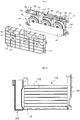
FIG. 1 is a perspective view of a battery cooling apparatus according to an embodiment of the present disclosure. -
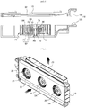
FIG. 2 is a cross-sectional view of a battery cooling apparatus according to an embodiment of the present disclosure. -
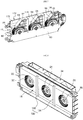
FIG. 3 is an exploded perspective view of a battery cooling apparatus according to an embodiment of the present disclosure. -
FIG. 4 is a side view of a battery cooling apparatus according to an embodiment of the present disclosure, in which the battery cooling apparatus is installed in a battery pack. -
FIG. 5 is a cross-sectional view illustrating a housing and a cooling fan of a battery cooling apparatus according to an embodiment of the present disclosure. -
FIG. 6 is a perspective view of discharge ports of a battery cooling apparatus according to another embodiment of the present disclosure. -
FIG. 7 is a perspective view of a duct portion of a battery cooling apparatus according to another embodiment of the present disclosure. -
FIG. 8 is a perspective view of a structure of suction ports of a battery cooling apparatus according to another embodiment of the present disclosure. -
FIG. 9 is a cross-sectional view of a structure of suction ports according to another embodiment of the present disclosure. -
FIG. 10 is a plan view of a PCB according to another embodiment of the present disclosure. -
FIG. 11 is a plan view of a PCB according to another embodiment of the present disclosure. -
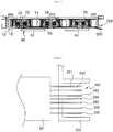
FIG. 12 is a plan view of a connector connecting structure according to an embodiment of the present disclosure. -
FIG. 13 is a cross-sectional view of a connector connecting structure according to another embodiment of the present disclosure. -
FIG. 14 is a cross-sectional view of a connector according to another embodiment of the present disclosure. - Hereinafter, embodiments of the present disclosure will be described in detail with reference to the accompanying drawings.The sizes and shapes of the components shown in the drawings may be exaggerated for clarity and convenience.In addition, terms defined in consideration of the configuration and operation of the present disclosure may vary depending on the intention or custom of the user, the operator, and the like.Definitions of these terms should be based on the content of this specification.
- Referring to
FIGS. 1 to 4 , a battery cooling apparatus according to an embodiment of the present disclosure includes: ahousing 10 installed on a side surface of abattery pack 100 and having asuction unit 30 through which air having passed through thebattery pack 100 is sucked and discharge ports through which air sucked through the suction unit is discharged to the outside; a plurality ofcooling fans 20 installed at intervals in thehousing 10 to generate air blowing power; and a printed circuit board (PCB) 50 installed in an inside of thehousing 10, in which the PCB 50 is electrically connected to the plurality ofcooling fans 20 to perform control operations of thecooling fans 20 and supply power to thecooling fans 20. - The
battery pack 100 includes a plurality ofbattery cells 110 spaced apart to form onebattery pack 100 and acooling apparatus 200 is installed on one side of the battery pack 100.When thecooling apparatus 200 is driven, air is sucked into the spaces between thebattery cells 110 to cool thebattery cells 110 while passing between thebattery cells 110. - A
suction duct 120, through which external air is sucked, may be separately installed on the other side of thebattery pack 100, that is, the side opposite to the side where thecooling apparatus 200 is installed. - As shown in
FIG. 5 , thehousing 10 includes afirst housing 12 having adischarge unit 40 formed therein and provided with acooling fan unit 20 and aPCB 50, and asecond housing 14 coupled to thefirst housing 12 andsuction ports 30 are formed therein. - The
cooling fans 20 may include afirst cooling fan 22, asecond cooling fan 24, and athird cooling fan 26, which are installed at predetermined intervals in the housing 10.Thecooling fans 20 may be two or three or more depending on the size of thebattery pack 100. - A plurality of
cooling fans 20 are disposed inside thehousing 10 and aguide unit 62 for guiding the air flow to radially discharge the air flowing in the axial direction of each of thecooling fans 20 is formed inside thehousing 10. - A
duct unit 66 for collecting air discharged from the plurality ofcooling fans 20 is formed on the upper side of each of theguide portions 62. Thedischarge port 40 through which air collected in theduct unit 66 is discharged to the outside is formed in the rear upper end of thehousing 10. - The
guide unit 62 includes afirst guide portion 152 mounted with afirst cooling fan 22 and guiding the air flow by thefirst cooling fan 22, asecond guide portion 154 mounted with asecond cooling fan 24 and guiding the air flow by thesecond cooling fan 24, and athird guide portion 156 mounted with athird cooling fan 26 and guiding the air flow by thethird cooling fan 26. - The
duct unit 66 includes afirst duct portion 162 formed on the upper surfaces of thefirst guide portion 152 and thesecond guide portion 154 and into which the air blown by thefirst cooling fan 22 and thesecond cooling fan 24 flows, and asecond duct portion 164 formed on the upper surface of thethird guide portion 156 and into which the air blown by thethird cooling fan 26 flows. - The
duct unit 66 may be formed as a single duct portion so that the air blown from the plurality ofcooling fans 20 can flow into one duct portion, or may be formed into three duct portions formed one by one for each of thecooling fans 20. - The
discharge unit 40 includes afirst discharge port 42 formed at the rear of thefirst duct portion 162 and discharging the air introduced into thefirst duct portion 162 to the outside, and asecond discharge port 44 formed in thesecond duct portion 164 and discharging the air introduced into thesecond duct portion 164 to the outside. - Similarly, the
discharge unit 40 may be formed as onedischarge port 40 when theduct unit 66 is formed in a single form, or may be formed as threedischarge ports 40 when theduct unit 66 is formed as three duct portions. - As described above, in the battery cooling apparatus according to the embodiment of the present disclosure, the
duct unit 66 through which the air is discharged is formed integrally with thehousing 10, so that there is no need to provide a separate duct structure for discharging air, to thereby reduce the number of parts and enable miniaturization of the battery cooling apparatus. - As shown in
FIGS. 6 and7 , aduct unit 170 according to another embodiment is formed to have a predetermined space on the upper surface of theguide unit 62 and has aninclined unit 64 which is extended from of theguide unit 62 at one side of theduct unit 170, so that air introduced into theduct unit 170 can be smoothly discharged via thedischarge unit 70. - The
duct unit 170 includes afirst duct portion 172 into which the air blown by thefirst cooling fan 22 flows, asecond duct portion 174 into which the air blown by thesecond cooling fan 24 flows, and athird duct portion 176 into which the air blown by thethird cooling fan 26 flows. - The
discharge unit 70 may be formed on an upper surface of theduct unit 170 so that air may be discharged in an upward direction of thehousing 10 and the air transferred from the plurality ofduct portions discharge unit 70 may be formed in the same number as that of the duct portions in theduct unit 170. - The
discharge unit 70 according to another embodiment may be formed on an upper surface of thehousing 10 so as to discharge air in an upward direction of thehousing 10, and may employ a type in which air is discharged to a rear side of thehousing 10 and a type in which air is discharged in an upward direction of thehousing 10 depending on the nature of the location where the battery cooling apparatus is installed. - Therefore, the battery cooling apparatus according to some embodiments of the present disclosure can also form the position of the discharge unit on the rear side of the housing, the upper side of the housing, and also the front side of the housing, in accordance with the characteristics of a portion where a battery such as an automobile is installed.
- The front surface of the
housing 10 is in close contact with one surface of the battery pack 100.Aspace portion 16 recessed inwardly is formed in the front surface of thehousing 10 attached to thebattery pack 100 so that air passing through thebattery cells 110 can be introduced into thespace portion 16. - That is, the front edge portion of the
housing 10 is in close contact with one surface of thebattery pack 100 to prevent air from leaking, and air that has passed through thebattery cells 110 flows into thespace portion 16, and is sucked through the plurality ofsuction ports 30 formed in thespace portion 16. - In the front surface of the
housing 10, thesuction ports 30 of the same number as that of the coolingfans 20 are formed.That is, thesuction unit 30 includes afirst suction port 32 through which air is sucked into thefirst cooling fan 22, asecond suction port 34 through which air is sucked by thesecond cooling fan 24, and athird suction port 36 through which air is sucked into thethird cooling fan 26. - The front surface of the
housing 10 in which thesuction unit 30 is formed is brought into close contact with the side surface of thebattery pack 100 to prevent air from leaking.Thespace portion 16 for securing a distance H between the suctionunit 30 and the side surface of thebattery pack 100 is formed on the front surface of thehousing 10 so as to allow air passing between thebattery cells 110 to flow in thespace portion 16. - The
space portion 16 is recessed inwardly of thehousing 10 from the front edge of thehousing 10 so that thesuction unit 30 is not directly connected to thebattery pack 100 due to thespace portion 16 between thesuction unit 30 and thebattery pack 100 and the air having passed through thebattery cells 110 is introduced into thespace portion 16 and sucked into thesuction unit 30. - Since the air that has passed through the
battery cells 110 flows into thespace portion 16 formed in thehousing 10 and then is guided to the coolingfans 20 through thesuction unit 30, wind pressure can be reduced and wind volume can be increased. - As shown in
FIGS. 8 and9 , apartition member 130 for preventing air blowing passage interference between the plurality of coolingfans 20 is formed on the front surface of thehousing 10. - The
partition member 130 divides thespace portion 16 into a plurality of partitions and includes afirst partition member 132 formed between thefirst suction port 32 and thesecond suction port 34 to prevent air introduced into thefirst suction port 32 and thesecond suction port 34 from interfering with each other, and asecond partition member 134 formed between thesecond suction port 34 and thethird suction port 36 to prevent air introduced into thesecond suction port 34 and thethird suction port 36 from interfering with each other. - The
space portion 16 is formed to be concave so as to have a distance H between thesuction unit 30 and thebattery pack 100. - The
first partition member 132 is protrudingly formed between thefirst suction port 32 and thesecond suction port 34 and thesecond partition member 134 protrudes is protrudingly formed between thesecond suction port 34 and thethird suction port 36. - The
space portion 16 includes afirst space 16a into which air sucked into thefirst suction port 32 flows, asecond space 16b into which air sucked into thesecond suction port 34 flows, and athird space 16c into which the air sucked into thethird suction port 36 flows. - As described above, when the front surface of the
housing 10 is divided into the plurality ofspaces partition members first space portion 16a is sucked only into thefirst suction port 32, the air introduced into thesecond space portion 16b is sucked only into thesecond suction port 34, and the air introduced into thethird space portion 16c is sucked into thethird suction port 36. Accordingly, it is possible to prevent occurrence of the air blowing passage interference between the cooling fans 20.When the air blowing passage interference between the coolingfans 20 is reduced, the vortex of the air flowing into thesuction unit 30 is reduced and the air volume can be increased. - Each of the cooling
fans 20 includes arotating shaft 74 rotatably supported by asupport 72 mounted on thehousing 10, astator 80 fixed to the outer circumferential surface of thesupport 72 and connected to thePCB 50, arotor 82 fixed to therotating shaft 74 and rotated together with the rotatingshaft 74, and ablade 84 installed in therotor 82 and sucking air in an axial direction of theblade 84 and discharging air in a radial direction of theblade 84. - The
stator 80 includes astator core 73 fixed to the outer circumferential surface of thesupport 72 and acoil 75 wound around thestator core 73. - The
rotor 82 includes amagnet 77 that is annularly arranged on the outer circumferential surface of thestator 80 with a predetermined gap therebetween and arotor support body 79 to which themagnet 77 is fixed and theblade 84 is integrally formed. - A
first bearing 86 and asecond bearing 88 are mounted in thesupport 72 to rotatably support the rotatingshaft 74. - As shown in
FIG. 10 , a PCBaccommodating portion 250 on which aPCB 50 is mounted is formed in the inside of thehousing 10. When thePCB 50 is placed on the PCBaccommodating portion 250 and then thefirst housing 12 and thesecond housing 14 are assembled, thePCB 50 is fixed to the inside of thehousing 10. - The PCB
accommodating portion 250 is formed on the inner surface of thehousing 10 so as to have a depth equal to the thickness of thePCB 50 so that when thePCB 50 is inserted into the PCBaccommodating portion 250, thePCB 50 and the inner surface of thehousing 10 are formed in the same plane so as not to interfere with the flow of air flowing into thehousing 10. - The PCB
accommodating portion 250 may be provided with a release preventing groove or a hook portion to which thePCB 50 is fitted to prevent thePCB 50 from being detached. ThePCB 50 may be fixed to the PCBaccommodating portion 250 by a method such as adhesion. - Therefore, no separate bolts or fixing parts are required for fixing the
PCB 50 to thehousing 10, so that an assembling process can be simplified and the number of components can be reduced. - The
PCB 50 is integrally formed with amain PCB 51 on which various circuit components are mounted and a plurality of sub-PCBs 90 integrally formed with themain PCB 51 and formed in the same number as the number of the coolingfans 20 so that the coolingfans 20 are fixed and electrically connected to each other. - The sub-PCBs 90 include a first sub-PCB 92 fixed to the
first cooling fan 22 to be electrically connected to thefirst cooling fan 22, a second sub-PCB 92 fixed to thesecond cooling fan 22 to be electrically connected to thesecond cooling fan 24, and a third sub-PCB 96 fixed to thethird cooling fan 26 to be electrically connected to thethird cooling fan 26. - Each of the sub-PCBs 90 is integrally formed on one surface of the
main PCB 51 and is formed to have acentral throughhole 98 through which therotating shaft 74 of the coolingfan 20 passes. - At least one of the sub-PCBs 90 may be separated from the main PCB and connected to the
main PCB 51 by a terminal. - As shown in
FIG. 10 , according to an embodiment of the sub-PCBs 90, the first sub-PCB 92 is integrally formed on themain PCB 51, and the second sub-PCB 94 is formed separately from themain PCB 51 and connected to connected via afirst terminal 260. The third sub-PCB 96 is formed separately from themain PCB 51 and connected to connected via asecond terminal 270. - As shown in
FIG. 11 , according to another embodiment of the sub-PCBs 90, the first sub-PCB 92 is separately formed from themain PCB 51 and electrically connected via the first terminal 182, the second sub-PCB 94 is formed separately from themain PCB 51 and is electrically connected via the second terminal 184, and the third sub-PCB 96 is formed separately from themain PCB 51 and is electrically connected via the second terminal 186. - At least one of the sub-PCBs 92, 94 and 96 is manufactured separately from the
main PCB 51 and is connected to themain PCB 51 via theterminals fan 20 is damaged or an error occurs in the sub-PCBs 92, 94, and 96, a replacement operation can be made conveniently. -
Terminals stator 80 of the coolingfan 20 and theterminals coils 75 of thestator 80 electrically. - A
first hole 610 through which therotating shaft 74 passes is formed in thehousing 10 and asecond hole 620 through which theterminals first hole 610. - When the
PCB 50 is mounted on the PCBaccommodating portion 250 of thehousing 10, theterminals first hole 620 to electrically connect each of theterminals coil 75. - The
main PCB 51 is connected to aconnector 180 through which external power and control signals can be exchanged. - As shown in
FIG. 12 , a plurality ofwires 190 drawn out from one side of thePCB 50 are connected to a connector 280 and fixed to thehousing 10 so as to be exposed to the outside.The plurality ofwires 190 may be formed of a wire harness in which a plurality of wires are combined, or may be formed in a flexible PCB shape with which theconnector 180 may be connected. - The plurality of
wires 190 include a pair ofpower connecting wires duty command wire 193 for controlling a motor RPM, apower control wire 194, and rotationalspeed applying wires fans 20, for applying a rotational speed signal of each coolingfan 20. - The connector according to an embodiment of the present disclosure is configured such that one
connector 180 is connected to thePCB 50 and a power connection and control signals of the plurality of coolingfans 20 can be exchanged through oneconnector 180, to thus simplify the structure of the battery cooing apparatus and the assembling process. - In the case of the conventional battery cooling apparatus, if three cooling fans are provided, two power supply connection wires are connected to each of the three cooling fans, to require six wires, three duty command wires are required for each cooling fan, and three rotational speed applying wires are required, and thus a total of 12 wires are connected together. There is a problem in that the structure is complicated and the assemblability is deteriorated.
- The connector according to the embodiment of the present disclosure can connect and control the power with three cooling
fans 20 by using only seven wires for oneconnector 180, thereby simplifying the structure. - As shown in
FIGS. 13 and 14 , a connector according to another embodiment includes a connector housing 240 formed integrally with thehousing 10 and having an external connector (not shown) to which a power connection wire and a control wire are connected, in which the external connector is inserted into the connector housing 240, and a plurality of connector pins 260 disposed within the connector housing 240 and connected to themain PCB 50. - One end of each of the connector pins 260 is fixed to the
PCB 50 by a method such as soldering and the other end thereof is arranged inside the connector housing and connected to the external connector. - The connector pins 260 include a pair of power connection pins 261 and 262 for supplying power to a plurality of wires, a
duty command pin 263 for controlling a motor RPM, apower control pin 264, and rotationalspeed applying pins fans 20 and for applying a rotation speed signal of each coolingfan 20. - The connector according to another embodiment is configured so that the connector housing 240 is formed integrally with the
housing 10 and the connector pins 260 are connected to themain PCB 50 and thus a separate connector is unnecessary to thereby simplify the structure, reduce the number of parts, and improve the assemblability. - While the present disclosure has been particularly shown and described with reference to exemplary embodiments thereof, by way of illustration and example only, it is clearly understood that the present disclosure is not to be construed as limiting the invention, and various changes and modifications may be made by those skilled in the art within the protective scope of the invention without departing off the spirit of the invention.
- The battery cooling apparatus according to the present disclosure is mounted on a high capacity battery used in an electric vehicle or a hybrid vehicle to cool the heat generated during repeated charging and discharging of the battery to prolong the life of the battery, and performs battery cooling with a plurality of cooling fans so that the battery can be uniformly cooled, in which the plurality of cooling fans can be installed in one housing, thereby enabling miniaturization.
Claims (15)
- A battery cooling apparatus comprising:a housing installed in a battery pack and having a suction unit through which air having passed through the battery pack is sucked and a discharge unit through which air sucked through the suction unit is discharged to the outside;a plurality of cooling fans installed at intervals in the housing to suck air through the suction unit and discharge air through the discharge unit; anda printed circuit board (PCB) installed in an inside of the housing, in which the PCB is fixed and electrically connected to the plurality of cooling fans to thus control operations of the cooling fans.
- The battery cooling apparatus of claim 1, whereinthe PCB comprises: a main PCB; and a plurality of sub-PCBs formed integrally with the main PCB and formed in the same number as the number of the cooling fans, in which the plurality of cooling fans are fixed and electrically connected to the plurality of sub-PCBs.
- The battery cooling apparatus of claim 2, whereineach of the sub-PCBs includes a central throughhole through which a rotating shaft of the cooling fan passes, in which a plurality of terminals electrically connected to the cooling fan are mounted.
- The battery cooling apparatus of claim 2, whereinat least one of the sub-PCBs is separated from the main PCB and connected to the main PCB by a terminal.
- The battery cooling apparatus of claim 3, whereinthe housing comprises a first hole portion through which the rotating shaft of the cooling fan passes and a second hole portion through which a terminal passes, in which the terminal is electrically connected to a coil of the stator by performing soldering through the second hole portion.
- The battery cooling apparatus of claim 1, whereinthe housing comprises: a first housing having the discharge unit formed therein and having the cooling fan and the PCB installed therein; and a second housing coupled to the first housing and having a plurality of the suction ports.
- The battery cooling apparatus of claim 1, whereina guide unit for guiding an air flow to radially discharge air flowing in an axial direction of the cooling fan, and a duct unit formed at an upper side of the guide unit for collecting air blown from the plurality of cooling fans, are formed in an inside of the housing.
- The battery cooling apparatus of claim 1, whereinthe discharge unit is formed on a rear surface of the housing to discharge air to a rear side of the housing, or is formed on an upper surface of the housing to discharge air in an upward direction of the housing.
- The battery cooling apparatus of claim 1, whereinthe suction unit formed on a front surface of the housing is equal to a number of the cooling fans.
- The battery cooling apparatus of claim 1, whereina space portion for securing a distance H between the suction unit and a side surface of the battery pack is formed on a front surface of the housing where the suction unit is formed.
- The battery cooling apparatus of claim 10, further comprising:a partitioning member mounted in the space portion and for partitioning between a plurality of suction ports to prevent occurrence of air blowing passage interference between the cooling fans.
- The battery cooling apparatus of claim 1, whereineach of the cooling fans comprises: a rotating shaft rotatably supported by a support portion formed in the housing; a stator fixed to an outer circumferential surface of the supporting portion and electrically connected to the PCB; a rotor fixed to the rotating shaft and rotated together with the rotating shaft; and a blade installed in the rotor in which air is sucked in an axial direction of the blade and air is radially discharged.
- The battery cooling apparatus of claim 1, whereinthe PCB further comprises a connector connected to the PCB via wires to control the plurality of cooling fans and supply power, in which the wires include a pair of power connecting wires for supplying power to the plurality of cooling fans, a duty command wire for controlling a motor RPM, a power control wire, and rotational speed applying wires provided in an identical number to that of the cooling fans, for applying a rotational speed signal of each cooling fan.
- The battery cooling apparatus of claim 1, further comprising:a connector connected to the PCB to control the plurality of cooling fans and supply power, in which the connector includes a connector housing formed integrally with the housing, and a plurality of connector pins fixed to an inside of the connector housing and connected to the PCB.
- The battery cooling apparatus of claim 14, whereinthe plurality of connector pins comprise a pair of power connection pins for supplying power to the plurality of cooling fans, a duty command pin for controlling the motor RPM, a power control pin, and a rotational speed applying pin for applying a rotational speed signal of each cooling fan.
Applications Claiming Priority (7)
| Application Number | Priority Date | Filing Date | Title |
|---|---|---|---|
| KR20150089940 | 2015-06-24 | ||
| KR1020150103099A KR101836184B1 (en) | 2015-07-21 | 2015-07-21 | Cooling system for battery |
| KR1020150103102A KR101836186B1 (en) | 2015-07-21 | 2015-07-21 | Cooling system for battery |
| KR1020150103100A KR101855685B1 (en) | 2015-07-21 | 2015-07-21 | Cooling system for battery |
| KR1020150103101A KR101836185B1 (en) | 2015-07-21 | 2015-07-21 | Cooling system for battery |
| KR1020150106668A KR101878356B1 (en) | 2015-06-24 | 2015-07-28 | Cooling system for battery |
| PCT/KR2016/006653 WO2016208972A1 (en) | 2015-06-24 | 2016-06-23 | Battery cooling apparatus |
Publications (3)
| Publication Number | Publication Date |
|---|---|
| EP3316392A1 true EP3316392A1 (en) | 2018-05-02 |
| EP3316392A4 EP3316392A4 (en) | 2019-04-03 |
| EP3316392B1 EP3316392B1 (en) | 2020-04-22 |
Family
ID=61046169
Family Applications (1)
| Application Number | Title | Priority Date | Filing Date |
|---|---|---|---|
| EP16814685.0A Active EP3316392B1 (en) | 2015-06-24 | 2016-06-23 | Battery cooling apparatus |
Country Status (2)
| Country | Link |
|---|---|
| EP (1) | EP3316392B1 (en) |
| CN (1) | CN107592946B (en) |
Cited By (2)
| Publication number | Priority date | Publication date | Assignee | Title |
|---|---|---|---|---|
| CN115663338A (en) * | 2022-10-27 | 2023-01-31 | 厦门海辰储能科技股份有限公司 | Energy storage device and energy storage equipment |
| CN116031535A (en) * | 2023-02-13 | 2023-04-28 | 南京莱迪新能源科技有限公司 | Multi-dimensional embedded heat dissipation assembly and method for lithium battery mobile power supply in echelon mode |
Family Cites Families (6)
| Publication number | Priority date | Publication date | Assignee | Title |
|---|---|---|---|---|
| KR20100101019A (en) * | 2005-05-31 | 2010-09-15 | 엘지전자 주식회사 | Outdoor unit for separate air conditioner |
| KR100911832B1 (en) * | 2007-05-31 | 2009-08-13 | 주식회사 아모텍 | High efficiency slim vacuum suction device and robot cleaner using the same |
| KR101264623B1 (en) * | 2010-09-28 | 2013-05-24 | 한라비스테온공조 주식회사 | Battery cooling device for vehicle |
| JP5527479B2 (en) * | 2011-03-30 | 2014-06-18 | 日本電気株式会社 | Fan chassis, fan unit, and communication device |
| WO2013080385A1 (en) * | 2011-12-02 | 2013-06-06 | 株式会社日立製作所 | Battery system |
| JP5862608B2 (en) * | 2013-05-28 | 2016-02-16 | 株式会社デンソー | Battery assembly |
-
2016
- 2016-06-23 CN CN201680026890.0A patent/CN107592946B/en active Active
- 2016-06-23 EP EP16814685.0A patent/EP3316392B1/en active Active
Cited By (4)
| Publication number | Priority date | Publication date | Assignee | Title |
|---|---|---|---|---|
| CN115663338A (en) * | 2022-10-27 | 2023-01-31 | 厦门海辰储能科技股份有限公司 | Energy storage device and energy storage equipment |
| CN115663338B (en) * | 2022-10-27 | 2023-12-15 | 厦门海辰储能科技股份有限公司 | Energy storage device and energy storage equipment |
| CN116031535A (en) * | 2023-02-13 | 2023-04-28 | 南京莱迪新能源科技有限公司 | Multi-dimensional embedded heat dissipation assembly and method for lithium battery mobile power supply in echelon mode |
| CN116031535B (en) * | 2023-02-13 | 2023-06-02 | 南京莱迪新能源科技有限公司 | Multi-dimensional embedded heat dissipation assembly and method for lithium battery mobile power supply in echelon mode |
Also Published As
| Publication number | Publication date |
|---|---|
| EP3316392A4 (en) | 2019-04-03 |
| CN107592946A (en) | 2018-01-16 |
| CN107592946B (en) | 2020-08-14 |
| EP3316392B1 (en) | 2020-04-22 |
Similar Documents
| Publication | Publication Date | Title |
|---|---|---|
| US20080219838A1 (en) | Centrifugal fan | |
| EP3316390B1 (en) | System for controlling multiple cooling fans for battery pack | |
| KR102286835B1 (en) | Air blower for vehicle | |
| CN101025165A (en) | Centrifugal fan | |
| US10113551B2 (en) | Axial flow fan | |
| EP2811627B1 (en) | Fan motor, inline type fan motor and assembly method of the same | |
| US10527040B2 (en) | Fluid machine for vehicle | |
| EP3322025A1 (en) | Battery cooling apparatus | |
| US20190191949A1 (en) | Blowing device and vacuum cleaner | |
| CN109578300B (en) | Centrifugal fan | |
| EP3316392B1 (en) | Battery cooling apparatus | |
| US20080143201A1 (en) | Methods and apparatus for cooling an electric motor | |
| EP3076025B1 (en) | Vacuum suction unit | |
| KR101836185B1 (en) | Cooling system for battery | |
| CN117167319A (en) | Blade components and hanging neck fans | |
| KR101855685B1 (en) | Cooling system for battery | |
| KR101836186B1 (en) | Cooling system for battery | |
| CN101714793B (en) | Coil support for rotating electrical machine | |
| KR101836184B1 (en) | Cooling system for battery | |
| JP6747394B2 (en) | Battery device | |
| KR101878356B1 (en) | Cooling system for battery | |
| CN211429123U (en) | Ventilation cooling structure for high-speed permanent magnet motor | |
| CN109904968B (en) | Motor and air supply device with same | |
| CN103791553B (en) | Air-conditioning module and air-conditioning | |
| CN208386341U (en) | A kind of high-speed motor |
Legal Events
| Date | Code | Title | Description |
|---|---|---|---|
| STAA | Information on the status of an ep patent application or granted ep patent |
Free format text: STATUS: THE INTERNATIONAL PUBLICATION HAS BEEN MADE |
|
| PUAI | Public reference made under article 153(3) epc to a published international application that has entered the european phase |
Free format text: ORIGINAL CODE: 0009012 |
|
| STAA | Information on the status of an ep patent application or granted ep patent |
Free format text: STATUS: REQUEST FOR EXAMINATION WAS MADE |
|
| 17P | Request for examination filed |
Effective date: 20171102 |
|
| AK | Designated contracting states |
Kind code of ref document: A1 Designated state(s): AL AT BE BG CH CY CZ DE DK EE ES FI FR GB GR HR HU IE IS IT LI LT LU LV MC MK MT NL NO PL PT RO RS SE SI SK SM TR |
|
| AX | Request for extension of the european patent |
Extension state: BA ME |
|
| DAV | Request for validation of the european patent (deleted) | ||
| DAX | Request for extension of the european patent (deleted) | ||
| RIN1 | Information on inventor provided before grant (corrected) |
Inventor name: LEE, DONG HOON Inventor name: KIM, BYUNG SOO Inventor name: UHM, HEE CHUL Inventor name: LEE, JONG HUN |
|
| A4 | Supplementary search report drawn up and despatched |
Effective date: 20190301 |
|
| RIC1 | Information provided on ipc code assigned before grant |
Ipc: H01M 10/613 20140101ALI20190225BHEP Ipc: H01M 10/63 20140101ALI20190225BHEP Ipc: H01M 10/6563 20140101AFI20190225BHEP Ipc: H01M 10/6556 20140101ALI20190225BHEP |
|
| GRAP | Despatch of communication of intention to grant a patent |
Free format text: ORIGINAL CODE: EPIDOSNIGR1 |
|
| STAA | Information on the status of an ep patent application or granted ep patent |
Free format text: STATUS: GRANT OF PATENT IS INTENDED |
|
| INTG | Intention to grant announced |
Effective date: 20200109 |
|
| GRAS | Grant fee paid |
Free format text: ORIGINAL CODE: EPIDOSNIGR3 |
|
| GRAA | (expected) grant |
Free format text: ORIGINAL CODE: 0009210 |
|
| STAA | Information on the status of an ep patent application or granted ep patent |
Free format text: STATUS: THE PATENT HAS BEEN GRANTED |
|
| AK | Designated contracting states |
Kind code of ref document: B1 Designated state(s): AL AT BE BG CH CY CZ DE DK EE ES FI FR GB GR HR HU IE IS IT LI LT LU LV MC MK MT NL NO PL PT RO RS SE SI SK SM TR |
|
| REG | Reference to a national code |
Ref country code: CH Ref legal event code: EP |
|
| REG | Reference to a national code |
Ref country code: IE Ref legal event code: FG4D |
|
| REG | Reference to a national code |
Ref country code: DE Ref legal event code: R096 Ref document number: 602016034709 Country of ref document: DE |
|
| REG | Reference to a national code |
Ref country code: AT Ref legal event code: REF Ref document number: 1261356 Country of ref document: AT Kind code of ref document: T Effective date: 20200515 |
|
| REG | Reference to a national code |
Ref country code: LT Ref legal event code: MG4D |
|
| REG | Reference to a national code |
Ref country code: NL Ref legal event code: MP Effective date: 20200422 |
|
| PG25 | Lapsed in a contracting state [announced via postgrant information from national office to epo] |
Ref country code: SE Free format text: LAPSE BECAUSE OF FAILURE TO SUBMIT A TRANSLATION OF THE DESCRIPTION OR TO PAY THE FEE WITHIN THE PRESCRIBED TIME-LIMIT Effective date: 20200422 Ref country code: FI Free format text: LAPSE BECAUSE OF FAILURE TO SUBMIT A TRANSLATION OF THE DESCRIPTION OR TO PAY THE FEE WITHIN THE PRESCRIBED TIME-LIMIT Effective date: 20200422 Ref country code: IS Free format text: LAPSE BECAUSE OF FAILURE TO SUBMIT A TRANSLATION OF THE DESCRIPTION OR TO PAY THE FEE WITHIN THE PRESCRIBED TIME-LIMIT Effective date: 20200822 Ref country code: NO Free format text: LAPSE BECAUSE OF FAILURE TO SUBMIT A TRANSLATION OF THE DESCRIPTION OR TO PAY THE FEE WITHIN THE PRESCRIBED TIME-LIMIT Effective date: 20200722 Ref country code: GR Free format text: LAPSE BECAUSE OF FAILURE TO SUBMIT A TRANSLATION OF THE DESCRIPTION OR TO PAY THE FEE WITHIN THE PRESCRIBED TIME-LIMIT Effective date: 20200723 Ref country code: PT Free format text: LAPSE BECAUSE OF FAILURE TO SUBMIT A TRANSLATION OF THE DESCRIPTION OR TO PAY THE FEE WITHIN THE PRESCRIBED TIME-LIMIT Effective date: 20200824 Ref country code: LT Free format text: LAPSE BECAUSE OF FAILURE TO SUBMIT A TRANSLATION OF THE DESCRIPTION OR TO PAY THE FEE WITHIN THE PRESCRIBED TIME-LIMIT Effective date: 20200422 Ref country code: NL Free format text: LAPSE BECAUSE OF FAILURE TO SUBMIT A TRANSLATION OF THE DESCRIPTION OR TO PAY THE FEE WITHIN THE PRESCRIBED TIME-LIMIT Effective date: 20200422 |
|
| REG | Reference to a national code |
Ref country code: AT Ref legal event code: MK05 Ref document number: 1261356 Country of ref document: AT Kind code of ref document: T Effective date: 20200422 |
|
| PG25 | Lapsed in a contracting state [announced via postgrant information from national office to epo] |
Ref country code: LV Free format text: LAPSE BECAUSE OF FAILURE TO SUBMIT A TRANSLATION OF THE DESCRIPTION OR TO PAY THE FEE WITHIN THE PRESCRIBED TIME-LIMIT Effective date: 20200422 Ref country code: RS Free format text: LAPSE BECAUSE OF FAILURE TO SUBMIT A TRANSLATION OF THE DESCRIPTION OR TO PAY THE FEE WITHIN THE PRESCRIBED TIME-LIMIT Effective date: 20200422 Ref country code: BG Free format text: LAPSE BECAUSE OF FAILURE TO SUBMIT A TRANSLATION OF THE DESCRIPTION OR TO PAY THE FEE WITHIN THE PRESCRIBED TIME-LIMIT Effective date: 20200722 Ref country code: HR Free format text: LAPSE BECAUSE OF FAILURE TO SUBMIT A TRANSLATION OF THE DESCRIPTION OR TO PAY THE FEE WITHIN THE PRESCRIBED TIME-LIMIT Effective date: 20200422 |
|
| PG25 | Lapsed in a contracting state [announced via postgrant information from national office to epo] |
Ref country code: AL Free format text: LAPSE BECAUSE OF FAILURE TO SUBMIT A TRANSLATION OF THE DESCRIPTION OR TO PAY THE FEE WITHIN THE PRESCRIBED TIME-LIMIT Effective date: 20200422 |
|
| REG | Reference to a national code |
Ref country code: DE Ref legal event code: R097 Ref document number: 602016034709 Country of ref document: DE |
|
| PG25 | Lapsed in a contracting state [announced via postgrant information from national office to epo] |
Ref country code: RO Free format text: LAPSE BECAUSE OF FAILURE TO SUBMIT A TRANSLATION OF THE DESCRIPTION OR TO PAY THE FEE WITHIN THE PRESCRIBED TIME-LIMIT Effective date: 20200422 Ref country code: IT Free format text: LAPSE BECAUSE OF FAILURE TO SUBMIT A TRANSLATION OF THE DESCRIPTION OR TO PAY THE FEE WITHIN THE PRESCRIBED TIME-LIMIT Effective date: 20200422 Ref country code: EE Free format text: LAPSE BECAUSE OF FAILURE TO SUBMIT A TRANSLATION OF THE DESCRIPTION OR TO PAY THE FEE WITHIN THE PRESCRIBED TIME-LIMIT Effective date: 20200422 Ref country code: SM Free format text: LAPSE BECAUSE OF FAILURE TO SUBMIT A TRANSLATION OF THE DESCRIPTION OR TO PAY THE FEE WITHIN THE PRESCRIBED TIME-LIMIT Effective date: 20200422 Ref country code: DK Free format text: LAPSE BECAUSE OF FAILURE TO SUBMIT A TRANSLATION OF THE DESCRIPTION OR TO PAY THE FEE WITHIN THE PRESCRIBED TIME-LIMIT Effective date: 20200422 Ref country code: AT Free format text: LAPSE BECAUSE OF FAILURE TO SUBMIT A TRANSLATION OF THE DESCRIPTION OR TO PAY THE FEE WITHIN THE PRESCRIBED TIME-LIMIT Effective date: 20200422 Ref country code: MC Free format text: LAPSE BECAUSE OF FAILURE TO SUBMIT A TRANSLATION OF THE DESCRIPTION OR TO PAY THE FEE WITHIN THE PRESCRIBED TIME-LIMIT Effective date: 20200422 Ref country code: CZ Free format text: LAPSE BECAUSE OF FAILURE TO SUBMIT A TRANSLATION OF THE DESCRIPTION OR TO PAY THE FEE WITHIN THE PRESCRIBED TIME-LIMIT Effective date: 20200422 Ref country code: ES Free format text: LAPSE BECAUSE OF FAILURE TO SUBMIT A TRANSLATION OF THE DESCRIPTION OR TO PAY THE FEE WITHIN THE PRESCRIBED TIME-LIMIT Effective date: 20200422 |
|
| REG | Reference to a national code |
Ref country code: CH Ref legal event code: PL |
|
| PG25 | Lapsed in a contracting state [announced via postgrant information from national office to epo] |
Ref country code: SK Free format text: LAPSE BECAUSE OF FAILURE TO SUBMIT A TRANSLATION OF THE DESCRIPTION OR TO PAY THE FEE WITHIN THE PRESCRIBED TIME-LIMIT Effective date: 20200422 Ref country code: PL Free format text: LAPSE BECAUSE OF FAILURE TO SUBMIT A TRANSLATION OF THE DESCRIPTION OR TO PAY THE FEE WITHIN THE PRESCRIBED TIME-LIMIT Effective date: 20200422 |
|
| PLBE | No opposition filed within time limit |
Free format text: ORIGINAL CODE: 0009261 |
|
| STAA | Information on the status of an ep patent application or granted ep patent |
Free format text: STATUS: NO OPPOSITION FILED WITHIN TIME LIMIT |
|
| 26N | No opposition filed |
Effective date: 20210125 |
|
| GBPC | Gb: european patent ceased through non-payment of renewal fee |
Effective date: 20200722 |
|
| PG25 | Lapsed in a contracting state [announced via postgrant information from national office to epo] |
Ref country code: LU Free format text: LAPSE BECAUSE OF NON-PAYMENT OF DUE FEES Effective date: 20200623 |
|
| REG | Reference to a national code |
Ref country code: BE Ref legal event code: MM Effective date: 20200630 |
|
| PG25 | Lapsed in a contracting state [announced via postgrant information from national office to epo] |
Ref country code: LI Free format text: LAPSE BECAUSE OF NON-PAYMENT OF DUE FEES Effective date: 20200630 Ref country code: CH Free format text: LAPSE BECAUSE OF NON-PAYMENT OF DUE FEES Effective date: 20200630 Ref country code: FR Free format text: LAPSE BECAUSE OF NON-PAYMENT OF DUE FEES Effective date: 20200630 Ref country code: IE Free format text: LAPSE BECAUSE OF NON-PAYMENT OF DUE FEES Effective date: 20200623 Ref country code: GB Free format text: LAPSE BECAUSE OF NON-PAYMENT OF DUE FEES Effective date: 20200722 |
|
| PG25 | Lapsed in a contracting state [announced via postgrant information from national office to epo] |
Ref country code: SI Free format text: LAPSE BECAUSE OF FAILURE TO SUBMIT A TRANSLATION OF THE DESCRIPTION OR TO PAY THE FEE WITHIN THE PRESCRIBED TIME-LIMIT Effective date: 20200422 Ref country code: BE Free format text: LAPSE BECAUSE OF NON-PAYMENT OF DUE FEES Effective date: 20200630 |
|
| PG25 | Lapsed in a contracting state [announced via postgrant information from national office to epo] |
Ref country code: FR Free format text: LAPSE BECAUSE OF NON-PAYMENT OF DUE FEES Effective date: 20200630 |
|
| PGRI | Patent reinstated in contracting state [announced from national office to epo] |
Ref country code: FR Effective date: 20210707 |
|
| PG25 | Lapsed in a contracting state [announced via postgrant information from national office to epo] |
Ref country code: TR Free format text: LAPSE BECAUSE OF FAILURE TO SUBMIT A TRANSLATION OF THE DESCRIPTION OR TO PAY THE FEE WITHIN THE PRESCRIBED TIME-LIMIT Effective date: 20200422 Ref country code: MT Free format text: LAPSE BECAUSE OF FAILURE TO SUBMIT A TRANSLATION OF THE DESCRIPTION OR TO PAY THE FEE WITHIN THE PRESCRIBED TIME-LIMIT Effective date: 20200422 Ref country code: CY Free format text: LAPSE BECAUSE OF FAILURE TO SUBMIT A TRANSLATION OF THE DESCRIPTION OR TO PAY THE FEE WITHIN THE PRESCRIBED TIME-LIMIT Effective date: 20200422 |
|
| PG25 | Lapsed in a contracting state [announced via postgrant information from national office to epo] |
Ref country code: MK Free format text: LAPSE BECAUSE OF FAILURE TO SUBMIT A TRANSLATION OF THE DESCRIPTION OR TO PAY THE FEE WITHIN THE PRESCRIBED TIME-LIMIT Effective date: 20200422 |
|
| PGFP | Annual fee paid to national office [announced via postgrant information from national office to epo] |
Ref country code: DE Payment date: 20250520 Year of fee payment: 10 |
|
| PGFP | Annual fee paid to national office [announced via postgrant information from national office to epo] |
Ref country code: FR Payment date: 20250521 Year of fee payment: 10 |