EP3316384A1 - Battery module with a fixing for a temperature sensitive element - Google Patents
Battery module with a fixing for a temperature sensitive element Download PDFInfo
- Publication number
- EP3316384A1 EP3316384A1 EP16195595.0A EP16195595A EP3316384A1 EP 3316384 A1 EP3316384 A1 EP 3316384A1 EP 16195595 A EP16195595 A EP 16195595A EP 3316384 A1 EP3316384 A1 EP 3316384A1
- Authority
- EP
- European Patent Office
- Prior art keywords
- battery
- circuit board
- printed circuit
- temperature sensitive
- sensitive element
- Prior art date
- Legal status (The legal status is an assumption and is not a legal conclusion. Google has not performed a legal analysis and makes no representation as to the accuracy of the status listed.)
- Granted
Links
- 230000001681 protective effect Effects 0.000 claims abstract description 37
- 239000006260 foam Substances 0.000 claims description 19
- 239000012777 electrically insulating material Substances 0.000 claims description 4
- 239000012790 adhesive layer Substances 0.000 claims description 3
- 210000004027 cell Anatomy 0.000 description 80
- 239000010410 layer Substances 0.000 description 10
- 238000004519 manufacturing process Methods 0.000 description 7
- 238000000034 method Methods 0.000 description 7
- 239000004065 semiconductor Substances 0.000 description 7
- 238000007599 discharging Methods 0.000 description 4
- PXHVJJICTQNCMI-UHFFFAOYSA-N Nickel Chemical compound [Ni] PXHVJJICTQNCMI-UHFFFAOYSA-N 0.000 description 3
- KDLHZDBZIXYQEI-UHFFFAOYSA-N Palladium Chemical compound [Pd] KDLHZDBZIXYQEI-UHFFFAOYSA-N 0.000 description 3
- 239000000853 adhesive Substances 0.000 description 3
- 230000001070 adhesive effect Effects 0.000 description 3
- 239000004020 conductor Substances 0.000 description 3
- 239000000463 material Substances 0.000 description 3
- 238000005476 soldering Methods 0.000 description 3
- 239000004698 Polyethylene Substances 0.000 description 2
- 239000004642 Polyimide Substances 0.000 description 2
- 239000010949 copper Substances 0.000 description 2
- 229920001971 elastomer Polymers 0.000 description 2
- 239000008151 electrolyte solution Substances 0.000 description 2
- 239000010931 gold Substances 0.000 description 2
- 229920000573 polyethylene Polymers 0.000 description 2
- 229920001721 polyimide Polymers 0.000 description 2
- 229910000679 solder Inorganic materials 0.000 description 2
- 239000010936 titanium Substances 0.000 description 2
- RYGMFSIKBFXOCR-UHFFFAOYSA-N Copper Chemical compound [Cu] RYGMFSIKBFXOCR-UHFFFAOYSA-N 0.000 description 1
- WHXSMMKQMYFTQS-UHFFFAOYSA-N Lithium Chemical compound [Li] WHXSMMKQMYFTQS-UHFFFAOYSA-N 0.000 description 1
- RTAQQCXQSZGOHL-UHFFFAOYSA-N Titanium Chemical compound [Ti] RTAQQCXQSZGOHL-UHFFFAOYSA-N 0.000 description 1
- 230000004308 accommodation Effects 0.000 description 1
- 238000009529 body temperature measurement Methods 0.000 description 1
- 230000001413 cellular effect Effects 0.000 description 1
- 238000006243 chemical reaction Methods 0.000 description 1
- 238000004891 communication Methods 0.000 description 1
- 150000001875 compounds Chemical class 0.000 description 1
- 229910052802 copper Inorganic materials 0.000 description 1
- 230000007423 decrease Effects 0.000 description 1
- 230000001419 dependent effect Effects 0.000 description 1
- 230000006866 deterioration Effects 0.000 description 1
- 239000013013 elastic material Substances 0.000 description 1
- 239000000806 elastomer Substances 0.000 description 1
- 238000003487 electrochemical reaction Methods 0.000 description 1
- 239000003792 electrolyte Substances 0.000 description 1
- PCHJSUWPFVWCPO-UHFFFAOYSA-N gold Chemical compound [Au] PCHJSUWPFVWCPO-UHFFFAOYSA-N 0.000 description 1
- 229910052737 gold Inorganic materials 0.000 description 1
- 230000002427 irreversible effect Effects 0.000 description 1
- 229910052744 lithium Inorganic materials 0.000 description 1
- 238000005259 measurement Methods 0.000 description 1
- 229910052759 nickel Inorganic materials 0.000 description 1
- 229910052763 palladium Inorganic materials 0.000 description 1
- -1 polyethylene Polymers 0.000 description 1
- 239000002861 polymer material Substances 0.000 description 1
- 229920002635 polyurethane Polymers 0.000 description 1
- 239000004814 polyurethane Substances 0.000 description 1
- 239000000243 solution Substances 0.000 description 1
- 230000003068 static effect Effects 0.000 description 1
- 239000000126 substance Substances 0.000 description 1
- 229910052719 titanium Inorganic materials 0.000 description 1
Images


Classifications
-
- H—ELECTRICITY
- H01—ELECTRIC ELEMENTS
- H01M—PROCESSES OR MEANS, e.g. BATTERIES, FOR THE DIRECT CONVERSION OF CHEMICAL ENERGY INTO ELECTRICAL ENERGY
- H01M10/00—Secondary cells; Manufacture thereof
- H01M10/42—Methods or arrangements for servicing or maintenance of secondary cells or secondary half-cells
- H01M10/425—Structural combination with electronic components, e.g. electronic circuits integrated to the outside of the casing
-
- H—ELECTRICITY
- H01—ELECTRIC ELEMENTS
- H01M—PROCESSES OR MEANS, e.g. BATTERIES, FOR THE DIRECT CONVERSION OF CHEMICAL ENERGY INTO ELECTRICAL ENERGY
- H01M10/00—Secondary cells; Manufacture thereof
- H01M10/04—Construction or manufacture in general
- H01M10/0481—Compression means other than compression means for stacks of electrodes and separators
-
- H—ELECTRICITY
- H01—ELECTRIC ELEMENTS
- H01M—PROCESSES OR MEANS, e.g. BATTERIES, FOR THE DIRECT CONVERSION OF CHEMICAL ENERGY INTO ELECTRICAL ENERGY
- H01M10/00—Secondary cells; Manufacture thereof
- H01M10/42—Methods or arrangements for servicing or maintenance of secondary cells or secondary half-cells
- H01M10/48—Accumulators combined with arrangements for measuring, testing or indicating the condition of cells, e.g. the level or density of the electrolyte
- H01M10/486—Accumulators combined with arrangements for measuring, testing or indicating the condition of cells, e.g. the level or density of the electrolyte for measuring temperature
-
- H—ELECTRICITY
- H01—ELECTRIC ELEMENTS
- H01M—PROCESSES OR MEANS, e.g. BATTERIES, FOR THE DIRECT CONVERSION OF CHEMICAL ENERGY INTO ELECTRICAL ENERGY
- H01M10/00—Secondary cells; Manufacture thereof
- H01M10/60—Heating or cooling; Temperature control
- H01M10/62—Heating or cooling; Temperature control specially adapted for specific applications
- H01M10/625—Vehicles
-
- H—ELECTRICITY
- H01—ELECTRIC ELEMENTS
- H01M—PROCESSES OR MEANS, e.g. BATTERIES, FOR THE DIRECT CONVERSION OF CHEMICAL ENERGY INTO ELECTRICAL ENERGY
- H01M10/00—Secondary cells; Manufacture thereof
- H01M10/60—Heating or cooling; Temperature control
- H01M10/63—Control systems
- H01M10/637—Control systems characterised by the use of reversible temperature-sensitive devices, e.g. NTC, PTC or bimetal devices; characterised by control of the internal current flowing through the cells, e.g. by switching
-
- H—ELECTRICITY
- H01—ELECTRIC ELEMENTS
- H01M—PROCESSES OR MEANS, e.g. BATTERIES, FOR THE DIRECT CONVERSION OF CHEMICAL ENERGY INTO ELECTRICAL ENERGY
- H01M50/00—Constructional details or processes of manufacture of the non-active parts of electrochemical cells other than fuel cells, e.g. hybrid cells
- H01M50/20—Mountings; Secondary casings or frames; Racks, modules or packs; Suspension devices; Shock absorbers; Transport or carrying devices; Holders
-
- H—ELECTRICITY
- H05—ELECTRIC TECHNIQUES NOT OTHERWISE PROVIDED FOR
- H05K—PRINTED CIRCUITS; CASINGS OR CONSTRUCTIONAL DETAILS OF ELECTRIC APPARATUS; MANUFACTURE OF ASSEMBLAGES OF ELECTRICAL COMPONENTS
- H05K1/00—Printed circuits
-
- H—ELECTRICITY
- H01—ELECTRIC ELEMENTS
- H01M—PROCESSES OR MEANS, e.g. BATTERIES, FOR THE DIRECT CONVERSION OF CHEMICAL ENERGY INTO ELECTRICAL ENERGY
- H01M10/00—Secondary cells; Manufacture thereof
- H01M10/42—Methods or arrangements for servicing or maintenance of secondary cells or secondary half-cells
- H01M10/425—Structural combination with electronic components, e.g. electronic circuits integrated to the outside of the casing
- H01M2010/4271—Battery management systems including electronic circuits, e.g. control of current or voltage to keep battery in healthy state, cell balancing
-
- H—ELECTRICITY
- H01—ELECTRIC ELEMENTS
- H01M—PROCESSES OR MEANS, e.g. BATTERIES, FOR THE DIRECT CONVERSION OF CHEMICAL ENERGY INTO ELECTRICAL ENERGY
- H01M2200/00—Safety devices for primary or secondary batteries
- H01M2200/10—Temperature sensitive devices
-
- H—ELECTRICITY
- H01—ELECTRIC ELEMENTS
- H01M—PROCESSES OR MEANS, e.g. BATTERIES, FOR THE DIRECT CONVERSION OF CHEMICAL ENERGY INTO ELECTRICAL ENERGY
- H01M2200/00—Safety devices for primary or secondary batteries
- H01M2200/10—Temperature sensitive devices
- H01M2200/105—NTC
-
- H—ELECTRICITY
- H01—ELECTRIC ELEMENTS
- H01M—PROCESSES OR MEANS, e.g. BATTERIES, FOR THE DIRECT CONVERSION OF CHEMICAL ENERGY INTO ELECTRICAL ENERGY
- H01M2200/00—Safety devices for primary or secondary batteries
- H01M2200/10—Temperature sensitive devices
- H01M2200/106—PTC
-
- H—ELECTRICITY
- H01—ELECTRIC ELEMENTS
- H01M—PROCESSES OR MEANS, e.g. BATTERIES, FOR THE DIRECT CONVERSION OF CHEMICAL ENERGY INTO ELECTRICAL ENERGY
- H01M2220/00—Batteries for particular applications
- H01M2220/20—Batteries in motive systems, e.g. vehicle, ship, plane
-
- H—ELECTRICITY
- H01—ELECTRIC ELEMENTS
- H01M—PROCESSES OR MEANS, e.g. BATTERIES, FOR THE DIRECT CONVERSION OF CHEMICAL ENERGY INTO ELECTRICAL ENERGY
- H01M50/00—Constructional details or processes of manufacture of the non-active parts of electrochemical cells other than fuel cells, e.g. hybrid cells
- H01M50/20—Mountings; Secondary casings or frames; Racks, modules or packs; Suspension devices; Shock absorbers; Transport or carrying devices; Holders
- H01M50/204—Racks, modules or packs for multiple batteries or multiple cells
- H01M50/207—Racks, modules or packs for multiple batteries or multiple cells characterised by their shape
- H01M50/209—Racks, modules or packs for multiple batteries or multiple cells characterised by their shape adapted for prismatic or rectangular cells
-
- Y—GENERAL TAGGING OF NEW TECHNOLOGICAL DEVELOPMENTS; GENERAL TAGGING OF CROSS-SECTIONAL TECHNOLOGIES SPANNING OVER SEVERAL SECTIONS OF THE IPC; TECHNICAL SUBJECTS COVERED BY FORMER USPC CROSS-REFERENCE ART COLLECTIONS [XRACs] AND DIGESTS
- Y02—TECHNOLOGIES OR APPLICATIONS FOR MITIGATION OR ADAPTATION AGAINST CLIMATE CHANGE
- Y02E—REDUCTION OF GREENHOUSE GAS [GHG] EMISSIONS, RELATED TO ENERGY GENERATION, TRANSMISSION OR DISTRIBUTION
- Y02E60/00—Enabling technologies; Technologies with a potential or indirect contribution to GHG emissions mitigation
- Y02E60/10—Energy storage using batteries
-
- Y—GENERAL TAGGING OF NEW TECHNOLOGICAL DEVELOPMENTS; GENERAL TAGGING OF CROSS-SECTIONAL TECHNOLOGIES SPANNING OVER SEVERAL SECTIONS OF THE IPC; TECHNICAL SUBJECTS COVERED BY FORMER USPC CROSS-REFERENCE ART COLLECTIONS [XRACs] AND DIGESTS
- Y02—TECHNOLOGIES OR APPLICATIONS FOR MITIGATION OR ADAPTATION AGAINST CLIMATE CHANGE
- Y02T—CLIMATE CHANGE MITIGATION TECHNOLOGIES RELATED TO TRANSPORTATION
- Y02T10/00—Road transport of goods or passengers
- Y02T10/60—Other road transportation technologies with climate change mitigation effect
- Y02T10/70—Energy storage systems for electromobility, e.g. batteries
Definitions
- the present invention relates to a battery module comprising a specific arrangement of a fixing between a protective circuit module and a temperature sensitive element suitable for measurement of a battery cell temperature.
- a rechargeable or secondary battery differs from a primary battery in that it can be repeatedly charged and discharged, while the latter provides only an irreversible conversion of chemical to electrical energy.
- Low-capacity rechargeable batteries are used as power supply for small electronic devices, such as cellular phones, notebook computers and camcorders, while high-capacity rechargeable batteries are used as the power supply for hybrid vehicles and the like.
- rechargeable batteries include an electrode assembly including a positive electrode, a negative electrode, and a separator interposed between the positive and negative electrodes, a case receiving the electrode assembly, and an electrode terminal electrically connected to the electrode assembly.
- An electrolyte solution is injected into the case in order to enable charging and discharging of the battery via an electrochemical reaction of the positive electrode, the negative electrode, and the electrolyte solution.
- the shape of the case e.g. cylindrical or rectangular, depends on the battery's intended purpose.
- Rechargeable batteries may be used as a battery module formed of a plurality of unit battery cells coupled in series and/or in parallel so as to provide a high energy density, e.g. for motor driving of a hybrid vehicle. That is, the battery module is formed by interconnecting the electrode terminals of the plurality of unit battery cells depending on a required amount of power and in order to realize a high-power rechargeable battery, e.g. for an electric vehicle.
- Battery modules can be constructed either in block design or in modular design. In block designs each battery is coupled to a common current collector structure and a common battery management system and the unit thereof is housed. In modular designs, pluralities of battery cells are connected to form submodules and several submodules are connected to form the module. The battery management functions can then be at least partially realized on either module or submodule level and thus interchangeability might be improved.
- One or more battery modules are mechanically and electrically integrated, equipped with a thermal management system and set up for communication with one or more electrical consumers in order to form a battery system.
- the thermal management system includes usually a protective circuit module which is arranged next to the battery cells.
- a battery module comprising:
- one aspect of the present invention is to provide a battery module, wherein a position and functionality of the temperature sensitive element at the surface of the battery cell is even ensured when a relative move of the battery cell and the protective circuit module occurs due to external impact. Furthermore, the manufacturing process should be still simply to keep the manufacturing costs low. This is achieved by arranging the temperature sensitive elements directly on the surface of the battery cell and connecting it with the protective circuit module by means of a flexible printed circuit board.
- a flexible circuit in its purest form is a vast array of conductors bonded to a thin dielectric film. Flex circuits require less manual labor during assembly and reduce production errors. Flex circuits have an intrinsic ability to integrate form, fit and function. Flex circuits eliminate the high cost of routing, wrapping and soldering wires. As a result, wiring errors are eliminated and hence manufacturing costs are reduced. However, rigid flex circuits provide higher component density and thus the protective circuit module cannot be established as a flexible printed circuit board itself. Hence, the battery module of the present invention combines the benefits of rigid and flexible circuits.
- the rigid printed circuit board includes a slit and the flexible printed circuit board is extending from the temperature sensitive element through the slit to an upper surface of the rigid printed circuit board and is being coupled to the protective circuit module at the upper surface of the rigid printed circuit board.
- a connection between the temperature sensor and the protective circuit module is achieved at the upper surface of the rigid printed circuit board.
- the flexible printed circuit board does not pass an outer edge of the rigid printed circuit board to reach the upper surface but passes a designated slit within the rigid printed circuit board. A contact between a wiring pattern of the rigid printed circuit board and the flexible printed circuit board may thus be easily established from the upper side of the battery module, for example by a common soldering process.
- the battery module includes a foam member being arranged between a lower surface of the rigid printed circuit board and the temperature sensitive element.
- the foam member may be made of an electrically insulating material, especially an elastic polymer material.
- Such a foam member can be easily provided at the designated place.
- a flexible printed circuit board provided with a temperature sensitive element at one of its ends may be fixed by an adhesive to a surface of the battery cell. Afterwards, a foam member is placed upon the temperature sensitive element and the other end of the flexible printed circuit board is passed through the slit when the protection circuit module is being mounted.
- the foam member may be established after mounting the protective circuit module by means of a foamable compound which is extruded into the gap between the temperature sensitive element and the rigid printed circuit board.
- a thermally conductive adhesive layer is provided between the temperature sensitive element and the surface of the battery cell.
- the flexible printed circuit board may thus be first soldered to the rigid printed circuit board.
- the end of the flexible printed circuit board bearing the temperature element is passed through the slit and fixed by the foam element at the rigid printed circuit board.
- temperature element is fixed at the foam member.
- the temperature element gets pressed to the cell surface.
- An adhesive between the temperature element and the cell surface may guarantee thermal contact.
- the foam member ensures the required contact pressure.
- a vehicle including a battery module as defined above is provided.
- the vehicle may be an automobile.
- spatially relative terms such as “beneath,” “below,” “lower,” “under,” “above,” “upper,” and the like, may be used herein for ease of explanation to describe one element or feature's relationship to another element(s) or feature(s) as illustrated in the figures. It will be understood that the spatially relative terms are intended to encompass different orientations of the device in use or in operation, in addition to the orientation depicted in the figures. For example, if the device in the figures is turned over, elements described as “below” or “beneath” or “under” other elements or features would then be oriented “above” the other elements or features. Thus, the example terms “below” and “under” can encompass both an orientation of above and below. The device may be otherwise oriented (e.g., rotated 90 degrees or at other orientations) and the spatially relative descriptors used herein should be interpreted accordingly.
- an exemplary embodiment of a conventional battery module 100 includes a plurality of battery cells 10 aligned in one direction and a heat exchange member 110 provided adjacent to a bottom surface of the plurality of battery cells 10.
- a pair of end plates 18 are provided to face wide surfaces of the battery cells 10 at the outside of the battery cells 10, and a connection plate 19 is configured to connect the pair of end plates 18 to each other thereby fixing the plurality of battery cells 10 together.
- Fastening portions 18a on both sides of the battery module 100 are fastened to a support plate 31 by bolts 40.
- the support plate 31 is part of a housing 30.
- an elastic member 120 made of rubber or other elastic materials may be interposed between the support plate 31 and the heat exchange member 110.
- each battery cell 10 is a prismatic (or rectangular) cell, the wide flat surfaces of the cells being stacked together to form the battery module.
- each battery cell 10 includes a battery case configured for accommodation of an electrode assembly and an electrolyte.
- the battery case is hermetically sealed by a cap assembly 14.
- the cap assembly 14 is provided with positive and negative electrode terminals 11 and 12 having different polarities, and a vent 13.
- the vent 13 is a safety means of the battery cell 10, which acts as a passage through which gas generated in the battery cell 10 is exhausted to the outside of the battery cell 10.
- the positive and negative electrode terminals 11 and 12 of neighboring battery cells 10 are electrically connected through a bus bar 15, and the bus bar 15 may be fixed by a nut 16 or the like.
- the battery module 100 may be used as power source unit by electrically connecting the plurality of battery cells 10 as one bundle.
- Rechargeable secondary batteries may be used as the battery cells 10, especially lithium secondary batteries.
- the battery module 100 may be a 48V battery for automotive application.
- the battery module 100 further includes a heat exchange member 110, which is provided adjacent to the bottom surface of the battery cells 10 so as to cool down the battery cells 10. Furthermore, the battery module 100 includes means for detecting the temperature of the battery cells 10 in order to safely operate the battery module 100. These means include a protective circuit module and temperature sensors (not shown in FIG. 1 ).
- FIG. 2 is a partially cut-away cross-sectional view of one of the battery cells 10 of the battery module 100 of FIG. 1 .
- FIG. 3 is an enlarged and schematic illustration of the area of FIG. 2 , where a temperature measurement of the battery cell 10 is performed.
- the battery module 100 includes a protective circuit module 130 electrically connected to the battery cell 10. Furthermore, the protective circuit module 130 is electrically connected to a temperature sensitive element 150 via a flexible printed circuit board 140.
- each battery cell 10 of the battery module 100 is electrically connected to a protective circuit module 130.
- there is only one protective circuit module 130 which is connected to all of the battery cells 10 of the battery module 100.
- the protective circuit module 130 is made to lie down at sides of the battery cells 10 such that there is a gap between the battery cell surface and the side of the protective circuit module 130 facing the battery cell 10.
- the protective circuit module 130 is being arranged at the upper surface of the battery cells 10 bearing the electrode terminals 11 and 12.
- the protective circuit module 130 is electrically connected to the battery cells 10 to control charging and discharging and preventing the battery cells 10 from being over-charged or over-discharged.
- the protective circuit module 130 includes a rigid printed circuit board (PCB) 131 with connection terminals 132a, 132b for the terminals 11, 12 of the battery cell 10 and at least one semiconductor device 133 is formed on an upper surface of the circuit board 131.
- the semiconductor device 133 may comprise an integrated circuit that is adapted to compare the measured temperature of the battery cell 10 with a limit value for allowable battery cell temperatures.
- the circuit board 131 includes a wiring pattern (not shown) formed on a surface of the circuit board 131.
- a main body of the circuit board 131 may be formed of a rigid electrically insulating material like polyimide (PI) or polyethylene (PET).
- the wiring pattern may be made of an electrically conductive material, such as copper (Cu), titanium (Ti), nickel (Ni), or palladium (Pd).
- connection terminals 132a and 132b may be formed by exposing a portion of the wiring pattern or - as implemented in the present embodiment - by further providing a conductive material, such as gold (Au), on the exposed portion of the wiring pattern.
- a conductive material such as gold (Au)
- the semiconductor device 133 applies signals for controlling operations of the battery cells 10.
- the semiconductor device 133 controls charging or discharging extents through high current lines of the battery cells 10.
- the semiconductor device 133 applies signals indicating voltages, current and temperatures of the battery cells 10 to prevent for example over-charge or over-discharge.
- the semiconductor device 133 applies information about the temperatures of the battery cells 10 via the flexible printed circuit board 140 from the temperature sensitive element 150 and controls the operations of the battery cells 10.
- the information about the voltages, currents and temperatures may be transferred to the semiconductor device 133 through the wiring pattern of the circuit board 131.
- each battery cell 10 of the battery module 100 includes at least one temperature sensitive element 150 in order to measure the temperature of each battery cell 10 separately. However, in several applications it is sufficient to arrange a minimum of two temperature sensitive elements 150 in the battery module 100.
- the flexible printed circuit board 140 includes sensing lines (not shown) for transmitting signals from the connected temperature sensitive element 150 to the protective circuit module 130, thereby allowing the protective circuit module 130 to identify temperature values of the corresponding battery cell 10.
- the flexible printed circuit board 140 extends between the protective circuit module 130 and the temperature sensitive element 150. Since the flexible printed circuit board 140 can be easily bent, a stable connection is maintained between the both components even if the battery cells 10 or the protective circuit module 130 move within the housing 30. More precisely, the flexible printed circuit board 140 extends through a slit 135 within the circuit board 131 and one end of the flexible printed circuit board 140 is electrically connected to a wiring pattern of the protective circuit module 130 at the upper surface of the circuit board 131. Thus, there are connectors (not shown) provided at the upper surface of circuit board 131 which may be contacted to sensing lines of the flexible printed circuit board 140 by for example a common soldering process.
- the temperature sensitive element 150 is provided on one surface of the battery cell 10.
- the temperature sensitive element 150 may be a temperature sensor, for instance a negative temperature coefficient (NTC) thermistor, the electrical resistance value of which decreases due to a negative temperature coefficient as the temperature of the battery cells 10 increases, or a positive temperature coefficient (PTC) thermistor, the electrical resistance value of which increases as the temperature of the battery cells 10 increases. Since the temperature sensitive element 150 sensitively reacts to temperature and alters resistance values with temperature, the protective circuit module 130 may control charging and discharging of the battery cells 10.
- NTC negative temperature coefficient
- PTC positive temperature coefficient
- the temperature sensitive element 150 is provided as a chip thermistor. Since the chip thermistor is simply connected to the circuit board 131 of the protective circuit module 130 via the flexible printed circuit board 140 by for example a solder mounting process, the number of overall process steps can be reduced. In addition, such solder mounting can be automated.
- a foam member 160 is provided between the protective circuit module 130 and a part of the flexible printed circuit board 140 bearing the temperature sensitive element 150.
- the temperature sensitive element 150 is pressed on the top side of the battery cell 10 with a foam body inserted between the flexible printed circuit board 140 bearing the temperature sensitive element 150 and the protective circuit module 130.
- the temperature sensitive element 150 may be fixed on the top surface of the battery cell 10 with a thermally conductive adhesive layer 170.
- the foam member 160 may be formed of an electrically insulating material.
- the foam member is made of a polymeric material, especially an elastomer which is able to damp relative movements between the battery cell 10 and the protective circuit module 130.
- Materials useful as foams include for example polyurethanes.
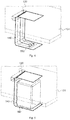
- FIG. 4 is a perspective view of a part of the battery module 100 including the temperature sensitive element 150 being coupled to the rigid printed circuit board 131 via the flexible printed circuit 140.
- the flexible printed circuit board 140 extends through the slit 135 of the rigid printed circuit board 131 from the side facing the battery cell to the side opposite to the battery cell.
- the flexible printed circuit board 140 is coupled to a wiring pattern (not shown) at the upper surface of the rigid printed circuit board 130.
- FIG. 5 is a similar perspective view of a part of the battery module 100 as illustrated in FIG. 4 except that the foam member 160 is also illustrated.
Abstract
- at least one battery cell;
- a protective circuit module electrically coupled to the battery cell and including a rigid printed circuit board;
- at least one temperature sensitive element provided at a surface of the battery cell; and
- a flexible printed circuit board electrically connecting the protective circuit module and the temperature sensitive element.
Description
- The present invention relates to a battery module comprising a specific arrangement of a fixing between a protective circuit module and a temperature sensitive element suitable for measurement of a battery cell temperature.
- A rechargeable or secondary battery differs from a primary battery in that it can be repeatedly charged and discharged, while the latter provides only an irreversible conversion of chemical to electrical energy. Low-capacity rechargeable batteries are used as power supply for small electronic devices, such as cellular phones, notebook computers and camcorders, while high-capacity rechargeable batteries are used as the power supply for hybrid vehicles and the like.
- In general, rechargeable batteries include an electrode assembly including a positive electrode, a negative electrode, and a separator interposed between the positive and negative electrodes, a case receiving the electrode assembly, and an electrode terminal electrically connected to the electrode assembly. An electrolyte solution is injected into the case in order to enable charging and discharging of the battery via an electrochemical reaction of the positive electrode, the negative electrode, and the electrolyte solution. The shape of the case, e.g. cylindrical or rectangular, depends on the battery's intended purpose.
- Rechargeable batteries may be used as a battery module formed of a plurality of unit battery cells coupled in series and/or in parallel so as to provide a high energy density, e.g. for motor driving of a hybrid vehicle. That is, the battery module is formed by interconnecting the electrode terminals of the plurality of unit battery cells depending on a required amount of power and in order to realize a high-power rechargeable battery, e.g. for an electric vehicle.
- Battery modules can be constructed either in block design or in modular design. In block designs each battery is coupled to a common current collector structure and a common battery management system and the unit thereof is housed. In modular designs, pluralities of battery cells are connected to form submodules and several submodules are connected to form the module. The battery management functions can then be at least partially realized on either module or submodule level and thus interchangeability might be improved. One or more battery modules are mechanically and electrically integrated, equipped with a thermal management system and set up for communication with one or more electrical consumers in order to form a battery system. The thermal management system includes usually a protective circuit module which is arranged next to the battery cells.
- For meeting the dynamic power demands of various electrical consumers connected to the battery system a static control of battery power output and charging is not sufficient. Thus, steady exchange of information between the battery system and the controllers of the electrical consumers is required. These information includes the battery systems actual state of charge (SoC), potential electrical performance, charging ability and internal resistance as well as actual or predicted power demands or surpluses of the consumers. One parameter controlling the state of each battery cell is the battery cell temperature. Therefore, temperature sensitive elements are provided within the battery module. Meanwhile, some solutions have been provided as how to keep the temperature sensitive element at the surface of the battery cell, since especially in automotive applications there may be strong external impacts. Each of these attempts includes mechanical complex arrangements of fixings with several parts thereby increasing significantly the costs of the battery module due to high manufacturing and material costs.
- It is thus an object of the present invention to overcome or reduce at least some of the drawbacks of the prior art and to provide a battery system that may be established by a simple manufacturing process using non-expensive elements.
- One or more of the drawbacks of the prior art could be avoided or at least reduced by means of the present invention. In particular, a battery module is provided comprising:
- at least one battery cell;
- a protective circuit module electrically coupled to the battery cell and including a rigid printed circuit board;
- at least one temperature sensitive element provided at a surface of the battery cell; and
- a flexible printed circuit board electrically connecting the protective circuit module
- Thus, one aspect of the present invention is to provide a battery module, wherein a position and functionality of the temperature sensitive element at the surface of the battery cell is even ensured when a relative move of the battery cell and the protective circuit module occurs due to external impact. Furthermore, the manufacturing process should be still simply to keep the manufacturing costs low. This is achieved by arranging the temperature sensitive elements directly on the surface of the battery cell and connecting it with the protective circuit module by means of a flexible printed circuit board.
- A flexible circuit in its purest form is a vast array of conductors bonded to a thin dielectric film. Flex circuits require less manual labor during assembly and reduce production errors. Flex circuits have an intrinsic ability to integrate form, fit and function. Flex circuits eliminate the high cost of routing, wrapping and soldering wires. As a result, wiring errors are eliminated and hence manufacturing costs are reduced. However, rigid flex circuits provide higher component density and thus the protective circuit module cannot be established as a flexible printed circuit board itself. Hence, the battery module of the present invention combines the benefits of rigid and flexible circuits.
- According to one embodiment, the rigid printed circuit board includes a slit and the flexible printed circuit board is extending from the temperature sensitive element through the slit to an upper surface of the rigid printed circuit board and is being coupled to the protective circuit module at the upper surface of the rigid printed circuit board. In other words, a connection between the temperature sensor and the protective circuit module is achieved at the upper surface of the rigid printed circuit board. The flexible printed circuit board does not pass an outer edge of the rigid printed circuit board to reach the upper surface but passes a designated slit within the rigid printed circuit board. A contact between a wiring pattern of the rigid printed circuit board and the flexible printed circuit board may thus be easily established from the upper side of the battery module, for example by a common soldering process.
- According to another embodiment of the present invention, the battery module includes a foam member being arranged between a lower surface of the rigid printed circuit board and the temperature sensitive element. The foam member may be made of an electrically insulating material, especially an elastic polymer material. Such a foam member can be easily provided at the designated place. For example, a flexible printed circuit board provided with a temperature sensitive element at one of its ends may be fixed by an adhesive to a surface of the battery cell. Afterwards, a foam member is placed upon the temperature sensitive element and the other end of the flexible printed circuit board is passed through the slit when the protection circuit module is being mounted. According to an alternative manufacturing process, the foam member may be established after mounting the protective circuit module by means of a foamable compound which is extruded into the gap between the temperature sensitive element and the rigid printed circuit board.
- According to a further embodiment of the present invention, a thermally conductive adhesive layer is provided between the temperature sensitive element and the surface of the battery cell. Thereby, the position of the temperature sensitive element on the surface of the battery cell could be fixed. In alternative, the flexible printed circuit board may thus be first soldered to the rigid printed circuit board. The end of the flexible printed circuit board bearing the temperature element is passed through the slit and fixed by the foam element at the rigid printed circuit board. Then, temperature element is fixed at the foam member. During the assembly of the rigid printed circuit board at the top of the battery cells, the temperature element gets pressed to the cell surface. An adhesive between the temperature element and the cell surface may guarantee thermal contact. During the curing of the adhesive the foam member ensures the required contact pressure.
- According to another aspect of the present invention, a vehicle including a battery module as defined above is provided. The vehicle may be an automobile.
- Further aspects of the present invention could be learned from the dependent claims or the following description.
- Features will become apparent to those of ordinary skill in the art by describing in detail exemplary embodiments with reference to the attached drawings in which:
- FIG. 1
- illustrates a perspective view of a battery module.
- FIG. 2
- is a partially cut-away cross-sectional view of a battery cell according to the present invention.
- FIG. 3
- is an enlarged partially cut-away cross-sectional view perspective view of the battery cell according to
FIG. 2 . - FIG. 4
- is a perspective view of a part of the battery module including a temperature sensitive element being coupled to a rigid printed circuit board (PCB) via a flexible printed circuit.
- FIG. 5
- is a perspective view of a part of the battery module including a temperature sensitive element being coupled to a rigid printed circuit board (PCB) via a flexible printed circuit including a foam member.
- Features of the inventive concept and methods of accomplishing the same may be understood more readily by reference to the following detailed description of embodiments and the accompanying drawings. Hereinafter, example embodiments will be described in more detail with reference to the accompanying drawings, in which like reference numbers refer to like elements throughout. The present invention, however, may be embodied in various different forms, and should not be construed as being limited to only the illustrated embodiments herein. Rather, these embodiments are provided as examples so that this disclosure will be thorough and complete, and will fully convey the aspects and features of the present invention to those skilled in the art. Accordingly, processes, elements, and techniques that are not necessary to those having ordinary skill in the art for a complete understanding of the aspects and features of the present invention may not be described. Unless otherwise noted, like reference numerals denote like elements throughout the attached drawings and the written description, and thus, descriptions thereof will not be repeated. In the drawings, the relative sizes of elements, layers, and regions may be exaggerated for clarity.
- Spatially relative terms, such as "beneath," "below," "lower," "under," "above," "upper," and the like, may be used herein for ease of explanation to describe one element or feature's relationship to another element(s) or feature(s) as illustrated in the figures. It will be understood that the spatially relative terms are intended to encompass different orientations of the device in use or in operation, in addition to the orientation depicted in the figures. For example, if the device in the figures is turned over, elements described as "below" or "beneath" or "under" other elements or features would then be oriented "above" the other elements or features. Thus, the example terms "below" and "under" can encompass both an orientation of above and below. The device may be otherwise oriented (e.g., rotated 90 degrees or at other orientations) and the spatially relative descriptors used herein should be interpreted accordingly.
- It will be understood that when an element or layer is referred to as being "on," "connected to," or "coupled to" another element or layer, it can be directly on, connected to, or coupled to the other element or layer, or one or more intervening elements or layers may be present. In addition, it will also be understood that when an element or layer is referred to as being "between" two elements or layers, it can be the only element or layer between the two elements or layers, or one or more intervening elements or layers may also be present.
- Unless otherwise defined, all terms (including technical and scientific terms) used herein have the same meaning as commonly understood by one of ordinary skill in the art to which the present invention belongs. It will be further understood that terms, such as those defined in commonly used dictionaries, should be interpreted as having a meaning that is consistent with their meaning in the context of the relevant art and/or the present specification, and should not be interpreted in an idealized or overly formal sense, unless expressly so defined herein.
- Referring to
FIG. 1 , an exemplary embodiment of aconventional battery module 100 includes a plurality ofbattery cells 10 aligned in one direction and aheat exchange member 110 provided adjacent to a bottom surface of the plurality ofbattery cells 10. A pair ofend plates 18 are provided to face wide surfaces of thebattery cells 10 at the outside of thebattery cells 10, and aconnection plate 19 is configured to connect the pair ofend plates 18 to each other thereby fixing the plurality ofbattery cells 10 together.Fastening portions 18a on both sides of thebattery module 100 are fastened to asupport plate 31 bybolts 40. Thesupport plate 31 is part of ahousing 30. In addition, anelastic member 120 made of rubber or other elastic materials may be interposed between thesupport plate 31 and theheat exchange member 110. - Here, each
battery cell 10 is a prismatic (or rectangular) cell, the wide flat surfaces of the cells being stacked together to form the battery module. Further, eachbattery cell 10 includes a battery case configured for accommodation of an electrode assembly and an electrolyte. The battery case is hermetically sealed by a cap assembly 14. The cap assembly 14 is provided with positive andnegative electrode terminals vent 13. Thevent 13 is a safety means of thebattery cell 10, which acts as a passage through which gas generated in thebattery cell 10 is exhausted to the outside of thebattery cell 10. The positive andnegative electrode terminals battery cells 10 are electrically connected through abus bar 15, and thebus bar 15 may be fixed by anut 16 or the like. Hence, thebattery module 100 may be used as power source unit by electrically connecting the plurality ofbattery cells 10 as one bundle. Rechargeable secondary batteries may be used as thebattery cells 10, especially lithium secondary batteries. Thebattery module 100 may be a 48V battery for automotive application. - Generally, the
battery cells 10 generate a large amount of heat while being charged/discharged. The generated heat is accumulated in thebattery cells 10, thereby accelerating the deterioration of thebattery cells 10. Therefore, thebattery module 100 further includes aheat exchange member 110, which is provided adjacent to the bottom surface of thebattery cells 10 so as to cool down thebattery cells 10. Furthermore, thebattery module 100 includes means for detecting the temperature of thebattery cells 10 in order to safely operate thebattery module 100. These means include a protective circuit module and temperature sensors (not shown inFIG. 1 ). -
FIG. 2 is a partially cut-away cross-sectional view of one of thebattery cells 10 of thebattery module 100 ofFIG. 1 .FIG. 3 is an enlarged and schematic illustration of the area ofFIG. 2 , where a temperature measurement of thebattery cell 10 is performed. Referring toFIG. 2 and respectivelyFIG. 3 , thebattery module 100 includes aprotective circuit module 130 electrically connected to thebattery cell 10. Furthermore, theprotective circuit module 130 is electrically connected to a temperaturesensitive element 150 via a flexible printedcircuit board 140. - In general, each
battery cell 10 of thebattery module 100 is electrically connected to aprotective circuit module 130. According to the present embodiment, there is only oneprotective circuit module 130, which is connected to all of thebattery cells 10 of thebattery module 100. However, there may be also two or more separate protective circuit modules being connected to a group of battery cells or single battery cells. - The
protective circuit module 130 is made to lie down at sides of thebattery cells 10 such that there is a gap between the battery cell surface and the side of theprotective circuit module 130 facing thebattery cell 10. Here, theprotective circuit module 130 is being arranged at the upper surface of thebattery cells 10 bearing theelectrode terminals protective circuit module 130 is electrically connected to thebattery cells 10 to control charging and discharging and preventing thebattery cells 10 from being over-charged or over-discharged. - The
protective circuit module 130 includes a rigid printed circuit board (PCB) 131 withconnection terminals terminals battery cell 10 and at least onesemiconductor device 133 is formed on an upper surface of thecircuit board 131. Thesemiconductor device 133 may comprise an integrated circuit that is adapted to compare the measured temperature of thebattery cell 10 with a limit value for allowable battery cell temperatures. Thecircuit board 131 includes a wiring pattern (not shown) formed on a surface of thecircuit board 131. A main body of thecircuit board 131 may be formed of a rigid electrically insulating material like polyimide (PI) or polyethylene (PET). The wiring pattern may be made of an electrically conductive material, such as copper (Cu), titanium (Ti), nickel (Ni), or palladium (Pd). - The
connection terminals - The
semiconductor device 133 applies signals for controlling operations of thebattery cells 10. In particular, thesemiconductor device 133 controls charging or discharging extents through high current lines of thebattery cells 10. In addition, thesemiconductor device 133 applies signals indicating voltages, current and temperatures of thebattery cells 10 to prevent for example over-charge or over-discharge. - To this end, the
semiconductor device 133 applies information about the temperatures of thebattery cells 10 via the flexible printedcircuit board 140 from the temperaturesensitive element 150 and controls the operations of thebattery cells 10. Here, the information about the voltages, currents and temperatures may be transferred to thesemiconductor device 133 through the wiring pattern of thecircuit board 131. - The flexible printed
circuit board 140 connects theprotective circuit module 130 and the temperaturesensitive element 150 provided at a surface of thebattery cell 10. According to one embodiment, eachbattery cell 10 of thebattery module 100 includes at least one temperaturesensitive element 150 in order to measure the temperature of eachbattery cell 10 separately. However, in several applications it is sufficient to arrange a minimum of two temperaturesensitive elements 150 in thebattery module 100. - The flexible printed
circuit board 140 includes sensing lines (not shown) for transmitting signals from the connected temperaturesensitive element 150 to theprotective circuit module 130, thereby allowing theprotective circuit module 130 to identify temperature values of thecorresponding battery cell 10. - Further, the flexible printed
circuit board 140 extends between theprotective circuit module 130 and the temperaturesensitive element 150. Since the flexible printedcircuit board 140 can be easily bent, a stable connection is maintained between the both components even if thebattery cells 10 or theprotective circuit module 130 move within thehousing 30. More precisely, the flexible printedcircuit board 140 extends through aslit 135 within thecircuit board 131 and one end of the flexible printedcircuit board 140 is electrically connected to a wiring pattern of theprotective circuit module 130 at the upper surface of thecircuit board 131. Thus, there are connectors (not shown) provided at the upper surface ofcircuit board 131 which may be contacted to sensing lines of the flexible printedcircuit board 140 by for example a common soldering process. - The temperature
sensitive element 150 is provided on one surface of thebattery cell 10. The temperaturesensitive element 150 may be a temperature sensor, for instance a negative temperature coefficient (NTC) thermistor, the electrical resistance value of which decreases due to a negative temperature coefficient as the temperature of thebattery cells 10 increases, or a positive temperature coefficient (PTC) thermistor, the electrical resistance value of which increases as the temperature of thebattery cells 10 increases. Since the temperaturesensitive element 150 sensitively reacts to temperature and alters resistance values with temperature, theprotective circuit module 130 may control charging and discharging of thebattery cells 10. - Specifically, the temperature
sensitive element 150 is provided as a chip thermistor. Since the chip thermistor is simply connected to thecircuit board 131 of theprotective circuit module 130 via the flexible printedcircuit board 140 by for example a solder mounting process, the number of overall process steps can be reduced. In addition, such solder mounting can be automated. - In order to fix the temperature
sensitive element 150 at the upper surface of thebattery cell 10, afoam member 160 is provided between theprotective circuit module 130 and a part of the flexible printedcircuit board 140 bearing the temperaturesensitive element 150. Thus, the temperaturesensitive element 150 is pressed on the top side of thebattery cell 10 with a foam body inserted between the flexible printedcircuit board 140 bearing the temperaturesensitive element 150 and theprotective circuit module 130. Optionally, the temperaturesensitive element 150 may be fixed on the top surface of thebattery cell 10 with a thermally conductiveadhesive layer 170. - The
foam member 160 may be formed of an electrically insulating material. Preferably, the foam member is made of a polymeric material, especially an elastomer which is able to damp relative movements between thebattery cell 10 and theprotective circuit module 130. Materials useful as foams include for example polyurethanes. -
FIG. 4 is a perspective view of a part of thebattery module 100 including the temperaturesensitive element 150 being coupled to the rigid printedcircuit board 131 via the flexible printedcircuit 140. For purpose of illustration neither thebattery cell 10 nor thefoam member 160 is shown and the rigid printedcircuit board 131 is semitransparent plotted. As can be seen, the flexible printedcircuit board 140 extends through theslit 135 of the rigid printedcircuit board 131 from the side facing the battery cell to the side opposite to the battery cell. The flexible printedcircuit board 140 is coupled to a wiring pattern (not shown) at the upper surface of the rigid printedcircuit board 130. -
FIG. 5 is a similar perspective view of a part of thebattery module 100 as illustrated inFIG. 4 except that thefoam member 160 is also illustrated.
Claims (7)
- A battery module (100), comprising:- at least one battery cell (10);- a protective circuit module (130) electrically coupled to the battery cell (10) and including a rigid printed circuit board (131);- at least one temperature sensitive element (150) provided at a surface of the battery cell (10); and- a flexible printed circuit board (140) electrically connecting the protective circuit module (130) and the temperature sensitive element (150).
- The battery module of claim 1, wherein the rigid printed circuit board (131) includes a slit (135) and
wherein the flexible printed circuit board (140) is extending from the temperature sensitive element (150) through the slit (135) to an upper surface of the rigid printed circuit board (131) and is being coupled to the protective circuit module (130) at the upper surface of the rigid printed circuit board (131). - The battery module of claim 1 or 2, wherein the battery module (100) includes a foam member (160) being arranged between a lower surface of the rigid printed circuit board (131) and the temperature sensitive element (150).
- The battery module of one of the preceding claims, wherein the foam member (160) is made of an electrically insulating material.
- The battery module of one of the preceding claims, wherein the foam member (160) is configured to press the temperature sensitive element (150) on the top side of the battery cell (10).
- The battery module of one of the preceding claims, wherein a thermally conductive adhesive layer (170) is provided between the temperature sensitive element (150) and the surface of the battery cell (10).
- A vehicle including a battery module according to one of the preceding claims.
Priority Applications (5)
| Application Number | Priority Date | Filing Date | Title |
|---|---|---|---|
| EP16195595.0A EP3316384B1 (en) | 2016-10-25 | 2016-10-25 | Battery module with a fixing for a temperature sensitive element |
| KR1020170122623A KR102410002B1 (en) | 2016-10-25 | 2017-09-22 | Battery module with a fixing for a temperature sensitive element |
| PCT/KR2017/010554 WO2018080033A1 (en) | 2016-10-25 | 2017-09-25 | Battery module having fixing structure for temperature sensor |
| US16/342,147 US11127990B2 (en) | 2016-10-25 | 2017-09-25 | Battery module having fixing structure for temperature sensing element |
| CN201780066245.6A CN109891661B (en) | 2016-10-25 | 2017-09-25 | Battery module having fixing structure for temperature sensing element |
Applications Claiming Priority (1)
| Application Number | Priority Date | Filing Date | Title |
|---|---|---|---|
| EP16195595.0A EP3316384B1 (en) | 2016-10-25 | 2016-10-25 | Battery module with a fixing for a temperature sensitive element |
Publications (2)
| Publication Number | Publication Date |
|---|---|
| EP3316384A1 true EP3316384A1 (en) | 2018-05-02 |
| EP3316384B1 EP3316384B1 (en) | 2019-02-20 |
Family
ID=57206102
Family Applications (1)
| Application Number | Title | Priority Date | Filing Date |
|---|---|---|---|
| EP16195595.0A Active EP3316384B1 (en) | 2016-10-25 | 2016-10-25 | Battery module with a fixing for a temperature sensitive element |
Country Status (3)
| Country | Link |
|---|---|
| US (1) | US11127990B2 (en) |
| EP (1) | EP3316384B1 (en) |
| KR (1) | KR102410002B1 (en) |
Cited By (20)
| Publication number | Priority date | Publication date | Assignee | Title |
|---|---|---|---|---|
| EP3579300A1 (en) * | 2018-06-08 | 2019-12-11 | Samsung SDI Co., Ltd. | Battery protection circuit and battery pack including same |
| EP3671940A1 (en) * | 2018-12-21 | 2020-06-24 | Contemporary Amperex Technology Co., Limited | Battery module and manufacturing method thereof, battery pack and vehicle |
| EP3712982A1 (en) * | 2019-03-18 | 2020-09-23 | Dongguan NVT Technology Co., Ltd. | Electronic device |
| EP3799148A1 (en) * | 2019-09-30 | 2021-03-31 | Samsung SDI Co., Ltd. | Battery module with flexible interconnector |
| EP3920310A4 (en) * | 2019-11-19 | 2022-05-25 | Contemporary Amperex Technology Co., Limited | Battery module and vehicle |
| DE102020214815A1 (en) | 2020-11-25 | 2022-05-25 | Elringklinger Ag | Battery module and method for manufacturing a battery module |
| US11394087B2 (en) | 2018-12-11 | 2022-07-19 | Samsung Sdi Co., Ltd. | Battery module |
| EP4203139A1 (en) * | 2021-12-21 | 2023-06-28 | CALB Co., Ltd. | Battery apparatus |
| US11695189B2 (en) | 2020-01-09 | 2023-07-04 | Samsung Sdi Co., Ltd. | Battery system with flexible printed circuit |
| DE202022103903U1 (en) | 2022-06-10 | 2023-09-13 | Diehl Advanced Mobility GmbH | Temperature control and degassing arrangement for energy storage cells and energy storage |
| DE202022103901U1 (en) | 2022-06-10 | 2023-09-28 | Diehl Advanced Mobility GmbH | Cell connector for an energy storage and energy storage |
| DE202022103898U1 (en) | 2022-06-10 | 2023-09-28 | Diehl Advanced Mobility GmbH | Circuit board arrangement and energy storage |
| DE202022103899U1 (en) | 2022-06-10 | 2023-09-28 | Diehl Advanced Mobility GmbH | Cell contact system and energy storage |
| DE202022103900U1 (en) | 2022-06-10 | 2023-09-28 | Diehl Advanced Mobility GmbH | Cell connector for a cell contacting system and energy storage |
| DE202022103896U1 (en) | 2022-06-10 | 2023-09-28 | Diehl Advanced Mobility GmbH | Temperature sensor arrangement, arrangement of a circuit board with temperature sensor arrangement and energy storage |
| WO2023237430A1 (en) | 2022-06-10 | 2023-12-14 | Diehl Ako Stiftung & Co. Kg | Temperature-control and degassing assembly for energy storage cells, and energy store |
| WO2023237427A1 (en) | 2022-06-10 | 2023-12-14 | Diehl Ako Stiftung & Co. Kg | Cell-contacting system and energy accumulator |
| WO2023237423A2 (en) | 2022-06-10 | 2023-12-14 | Diehl Ako Stiftung & Co. Kg | Circuit board assembly and energy store |
| WO2023237422A2 (en) | 2022-06-10 | 2023-12-14 | Diehl Ako Stiftung & Co. Kg | Temperature sensor assembly, arrangement of a circuit board with a temperature sensor assembly and energy store |
| EP4261980A3 (en) * | 2022-03-23 | 2024-02-21 | Samsung SDI Co., Ltd. | Battery pack |
Families Citing this family (9)
| Publication number | Priority date | Publication date | Assignee | Title |
|---|---|---|---|---|
| KR102037045B1 (en) * | 2019-05-22 | 2019-10-28 | (주)경신전선 | Voltage sensing device of battery-pack for vehicle |
| CN112151894B (en) * | 2019-06-28 | 2022-04-26 | 宁德时代新能源科技股份有限公司 | Battery module |
| CN210628357U (en) * | 2019-11-19 | 2020-05-26 | 宁德时代新能源科技股份有限公司 | Battery module and vehicle |
| WO2021113251A1 (en) * | 2019-12-02 | 2021-06-10 | Briggs & Stratton, Llc | Cell module assemblies battery pack |
| US11552344B2 (en) * | 2020-02-28 | 2023-01-10 | Gentherm Gmbh | Flex foil substrate connector for sensing battery voltage and temperature |
| US11747215B2 (en) * | 2020-08-06 | 2023-09-05 | Nippon Mektron, Ltd. | Temperature measuring device |
| CN116632462A (en) | 2022-02-14 | 2023-08-22 | 莫仕连接器(成都)有限公司 | Battery connection module |
| US20230268570A1 (en) * | 2022-02-22 | 2023-08-24 | GM Global Technology Operations LLC | Battery cell group conductive temperature measurement system |
| KR20240047037A (en) * | 2022-10-04 | 2024-04-12 | 주식회사 엘지에너지솔루션 | A busbar assembly that is easy to measure the temperature of the busbar and a battery pack including the same |
Citations (6)
| Publication number | Priority date | Publication date | Assignee | Title |
|---|---|---|---|---|
| US20110039134A1 (en) * | 2009-08-12 | 2011-02-17 | Samsung Sdi Co., Ltd. | Heat transfer member for battery pack |
| US20120019061A1 (en) * | 2009-03-31 | 2012-01-26 | Sanyo Electric Co., Ltd. | Battery module, battery system and electric vehicle |
| US20120121940A1 (en) * | 2010-11-12 | 2012-05-17 | Kwangyoung Park | Battery pack |
| US20120251849A1 (en) * | 2011-03-31 | 2012-10-04 | Samsung Sdi Co., Ltd. | Battery pack |
| US20130164569A1 (en) * | 2011-12-21 | 2013-06-27 | Ford Global Technologies, Llc | Packaging of thermistor in a battery assembly |
| US20140147705A1 (en) * | 2012-11-27 | 2014-05-29 | Samsung Sdi Co., Ltd. | Battery pack |
Family Cites Families (16)
| Publication number | Priority date | Publication date | Assignee | Title |
|---|---|---|---|---|
| KR101147203B1 (en) | 2010-07-15 | 2012-05-25 | 삼성에스디아이 주식회사 | Rechargeable battery pack and manufacturing method of the same |
| US8822051B2 (en) | 2010-11-12 | 2014-09-02 | Samsung Sdi Co., Ltd. | Protection circuit module including thermistor and secondary battery pack having the same |
| KR101209984B1 (en) | 2010-11-23 | 2012-12-07 | 삼성에스디아이 주식회사 | Battery Pack |
| US9705161B2 (en) * | 2011-03-29 | 2017-07-11 | Sanyo Electric Co., Ltd. | Battery module, battery system, electric vehicle, mobile unit, electric power storage device, power supply device, and electric device |
| JP2012248299A (en) | 2011-05-25 | 2012-12-13 | Sanyo Electric Co Ltd | Battery module, battery system, electric vehicle, mobile object, power storage device and power supply device |
| TWI500204B (en) | 2012-03-21 | 2015-09-11 | Simplo Technology Co Ltd | Battery module |
| US20140120401A1 (en) * | 2012-10-30 | 2014-05-01 | Samsung Sdi Co., Ltd. | Connecting structure between circuit boards and battery pack having the same |
| DE102012223723A1 (en) | 2012-12-19 | 2014-06-26 | Robert Bosch Gmbh | Battery cell with monitoring circuit |
| US20140212695A1 (en) | 2013-01-30 | 2014-07-31 | Tesla Motors, Inc. | Flexible printed circuit as high voltage interconnect in battery modules |
| DE102013213524A1 (en) | 2013-07-10 | 2015-01-15 | Robert Bosch Gmbh | Electrical connector for a battery module |
| KR101706305B1 (en) | 2013-09-25 | 2017-02-13 | 주식회사 엘지화학 | Battery Module Having Temperature Sensor |
| CN105745772B (en) * | 2014-01-17 | 2018-10-19 | 三洋电机株式会社 | Supply unit |
| KR101717144B1 (en) | 2014-03-03 | 2017-03-16 | 주식회사 엘지화학 | Protection Circuit Module Including Temperature Sensing Member and Battery Pack Comprising the Same |
| KR101750489B1 (en) | 2014-11-24 | 2017-06-23 | 주식회사 엘지화학 | Temperature Sensor for Battery Module and Battery Module Having the Same |
| KR20160085621A (en) * | 2015-01-08 | 2016-07-18 | 삼성에스디아이 주식회사 | Battery module |
| KR101642341B1 (en) | 2015-01-28 | 2016-07-26 | 희성전자 주식회사 | Interface board for detecting temperature and voltage of battery for energy storage equipment |
-
2016
- 2016-10-25 EP EP16195595.0A patent/EP3316384B1/en active Active
-
2017
- 2017-09-22 KR KR1020170122623A patent/KR102410002B1/en active IP Right Grant
- 2017-09-25 US US16/342,147 patent/US11127990B2/en active Active
Patent Citations (6)
| Publication number | Priority date | Publication date | Assignee | Title |
|---|---|---|---|---|
| US20120019061A1 (en) * | 2009-03-31 | 2012-01-26 | Sanyo Electric Co., Ltd. | Battery module, battery system and electric vehicle |
| US20110039134A1 (en) * | 2009-08-12 | 2011-02-17 | Samsung Sdi Co., Ltd. | Heat transfer member for battery pack |
| US20120121940A1 (en) * | 2010-11-12 | 2012-05-17 | Kwangyoung Park | Battery pack |
| US20120251849A1 (en) * | 2011-03-31 | 2012-10-04 | Samsung Sdi Co., Ltd. | Battery pack |
| US20130164569A1 (en) * | 2011-12-21 | 2013-06-27 | Ford Global Technologies, Llc | Packaging of thermistor in a battery assembly |
| US20140147705A1 (en) * | 2012-11-27 | 2014-05-29 | Samsung Sdi Co., Ltd. | Battery pack |
Cited By (27)
| Publication number | Priority date | Publication date | Assignee | Title |
|---|---|---|---|---|
| US11050096B2 (en) | 2018-06-08 | 2021-06-29 | Samsung Sdi Co., Ltd. | Battery protection circuit and battery pack including same |
| EP3579300A1 (en) * | 2018-06-08 | 2019-12-11 | Samsung SDI Co., Ltd. | Battery protection circuit and battery pack including same |
| US11394087B2 (en) | 2018-12-11 | 2022-07-19 | Samsung Sdi Co., Ltd. | Battery module |
| EP3671940A1 (en) * | 2018-12-21 | 2020-06-24 | Contemporary Amperex Technology Co., Limited | Battery module and manufacturing method thereof, battery pack and vehicle |
| US11302990B2 (en) | 2018-12-21 | 2022-04-12 | Contemporary Amperex Technology Co., Limited | Battery module |
| EP3712982A1 (en) * | 2019-03-18 | 2020-09-23 | Dongguan NVT Technology Co., Ltd. | Electronic device |
| US11855262B2 (en) | 2019-03-18 | 2023-12-26 | Dongguan Nvt Technology Limited | Electronic device |
| US11575184B2 (en) * | 2019-03-18 | 2023-02-07 | Dongguan Nvt Technology Limited | Electronic equipment |
| EP3799148A1 (en) * | 2019-09-30 | 2021-03-31 | Samsung SDI Co., Ltd. | Battery module with flexible interconnector |
| EP3920310A4 (en) * | 2019-11-19 | 2022-05-25 | Contemporary Amperex Technology Co., Limited | Battery module and vehicle |
| US11695189B2 (en) | 2020-01-09 | 2023-07-04 | Samsung Sdi Co., Ltd. | Battery system with flexible printed circuit |
| DE102020214815A1 (en) | 2020-11-25 | 2022-05-25 | Elringklinger Ag | Battery module and method for manufacturing a battery module |
| EP4203139A1 (en) * | 2021-12-21 | 2023-06-28 | CALB Co., Ltd. | Battery apparatus |
| EP4261980A3 (en) * | 2022-03-23 | 2024-02-21 | Samsung SDI Co., Ltd. | Battery pack |
| DE202022103903U1 (en) | 2022-06-10 | 2023-09-13 | Diehl Advanced Mobility GmbH | Temperature control and degassing arrangement for energy storage cells and energy storage |
| DE202022103899U1 (en) | 2022-06-10 | 2023-09-28 | Diehl Advanced Mobility GmbH | Cell contact system and energy storage |
| DE202022103900U1 (en) | 2022-06-10 | 2023-09-28 | Diehl Advanced Mobility GmbH | Cell connector for a cell contacting system and energy storage |
| DE202022103896U1 (en) | 2022-06-10 | 2023-09-28 | Diehl Advanced Mobility GmbH | Temperature sensor arrangement, arrangement of a circuit board with temperature sensor arrangement and energy storage |
| WO2023237428A1 (en) | 2022-06-10 | 2023-12-14 | Diehl Ako Stiftung & Co. Kg | Cell connector for an energy storage device, and energy storage device |
| WO2023237430A1 (en) | 2022-06-10 | 2023-12-14 | Diehl Ako Stiftung & Co. Kg | Temperature-control and degassing assembly for energy storage cells, and energy store |
| WO2023237429A1 (en) | 2022-06-10 | 2023-12-14 | Diehl Ako Stiftung & Co. Kg | Cell connector for a cell contacting system, and energy storage device |
| WO2023237427A1 (en) | 2022-06-10 | 2023-12-14 | Diehl Ako Stiftung & Co. Kg | Cell-contacting system and energy accumulator |
| WO2023237423A2 (en) | 2022-06-10 | 2023-12-14 | Diehl Ako Stiftung & Co. Kg | Circuit board assembly and energy store |
| WO2023237422A2 (en) | 2022-06-10 | 2023-12-14 | Diehl Ako Stiftung & Co. Kg | Temperature sensor assembly, arrangement of a circuit board with a temperature sensor assembly and energy store |
| DE102022114656A1 (en) | 2022-06-10 | 2023-12-21 | Diehl Advanced Mobility GmbH | Temperature control and degassing arrangement for energy storage cells and energy storage |
| DE202022103898U1 (en) | 2022-06-10 | 2023-09-28 | Diehl Advanced Mobility GmbH | Circuit board arrangement and energy storage |
| DE202022103901U1 (en) | 2022-06-10 | 2023-09-28 | Diehl Advanced Mobility GmbH | Cell connector for an energy storage and energy storage |
Also Published As
| Publication number | Publication date |
|---|---|
| US11127990B2 (en) | 2021-09-21 |
| US20190237817A1 (en) | 2019-08-01 |
| EP3316384B1 (en) | 2019-02-20 |
| KR102410002B1 (en) | 2022-06-15 |
| KR20180045794A (en) | 2018-05-04 |
Similar Documents
| Publication | Publication Date | Title |
|---|---|---|
| EP3316384B1 (en) | Battery module with a fixing for a temperature sensitive element | |
| CN109891661B (en) | Battery module having fixing structure for temperature sensing element | |
| EP3316338B1 (en) | Battery module with a fixing for a temperature sensitive element | |
| US8603663B2 (en) | Battery pack | |
| US20210098765A1 (en) | Battery module with flexible interconnector | |
| US20060091891A1 (en) | Member for measurement of cell voltage and temperature in battery pack | |
| EP4053989A1 (en) | Battery module having busbar, battery pack and vehicle | |
| US20190326649A1 (en) | Battery module with thermocouple unit | |
| US20220285755A1 (en) | Top Cooling Type Battery Pack | |
| US9240618B2 (en) | Rechargeable battery and battery module | |
| KR102511550B1 (en) | Busbar for A Battery System and Battery System Having the Same | |
| EP3226342A1 (en) | Cell connection unit | |
| EP3316386B1 (en) | Connector part for a printed circuit board and a battery system comprising the printed circuit board and the connector part | |
| EP3799148B1 (en) | Battery module with flexible interconnector | |
| US8895183B2 (en) | External terminal assembly including a terminal holder coupled to a protection circuit substrate and battery pack including the same | |
| CN113906621B (en) | Battery module and battery pack including the same | |
| EP3890055B1 (en) | Battery system with a flexible printed circuit comprising a plurality of integrated circuits for voltage and temperature measurement | |
| US11394087B2 (en) | Battery module | |
| CN111313119B (en) | Battery module and method for assembling cell monitoring circuit carrier to battery module | |
| EP3346523B1 (en) | Battery system with a cell connecting unit | |
| KR20210116040A (en) | Battery module including novel sensing structure and battery pack comprising the same |
Legal Events
| Date | Code | Title | Description |
|---|---|---|---|
| STAA | Information on the status of an ep patent application or granted ep patent |
Free format text: STATUS: EXAMINATION IS IN PROGRESS |
|
| PUAI | Public reference made under article 153(3) epc to a published international application that has entered the european phase |
Free format text: ORIGINAL CODE: 0009012 |
|
| 17P | Request for examination filed |
Effective date: 20170615 |
|
| AK | Designated contracting states |
Kind code of ref document: A1 Designated state(s): AL AT BE BG CH CY CZ DE DK EE ES FI FR GB GR HR HU IE IS IT LI LT LU LV MC MK MT NL NO PL PT RO RS SE SI SK SM TR |
|
| AX | Request for extension of the european patent |
Extension state: BA ME |
|
| 17Q | First examination report despatched |
Effective date: 20180219 |
|
| GRAP | Despatch of communication of intention to grant a patent |
Free format text: ORIGINAL CODE: EPIDOSNIGR1 |
|
| STAA | Information on the status of an ep patent application or granted ep patent |
Free format text: STATUS: GRANT OF PATENT IS INTENDED |
|
| INTG | Intention to grant announced |
Effective date: 20181022 |
|
| GRAS | Grant fee paid |
Free format text: ORIGINAL CODE: EPIDOSNIGR3 |
|
| GRAA | (expected) grant |
Free format text: ORIGINAL CODE: 0009210 |
|
| STAA | Information on the status of an ep patent application or granted ep patent |
Free format text: STATUS: THE PATENT HAS BEEN GRANTED |
|
| AK | Designated contracting states |
Kind code of ref document: B1 Designated state(s): AL AT BE BG CH CY CZ DE DK EE ES FI FR GB GR HR HU IE IS IT LI LT LU LV MC MK MT NL NO PL PT RO RS SE SI SK SM TR |
|
| REG | Reference to a national code |
Ref country code: GB Ref legal event code: FG4D |
|
| REG | Reference to a national code |
Ref country code: CH Ref legal event code: EP |
|
| REG | Reference to a national code |
Ref country code: DE Ref legal event code: R096 Ref document number: 602016010064 Country of ref document: DE |
|
| REG | Reference to a national code |
Ref country code: AT Ref legal event code: REF Ref document number: 1099387 Country of ref document: AT Kind code of ref document: T Effective date: 20190315 |
|
| REG | Reference to a national code |
Ref country code: IE Ref legal event code: FG4D |
|
| REG | Reference to a national code |
Ref country code: LT Ref legal event code: MG4D |
|
| REG | Reference to a national code |
Ref country code: NL Ref legal event code: MP Effective date: 20190220 |
|
| PG25 | Lapsed in a contracting state [announced via postgrant information from national office to epo] |
Ref country code: SE Free format text: LAPSE BECAUSE OF FAILURE TO SUBMIT A TRANSLATION OF THE DESCRIPTION OR TO PAY THE FEE WITHIN THE PRESCRIBED TIME-LIMIT Effective date: 20190220 Ref country code: LT Free format text: LAPSE BECAUSE OF FAILURE TO SUBMIT A TRANSLATION OF THE DESCRIPTION OR TO PAY THE FEE WITHIN THE PRESCRIBED TIME-LIMIT Effective date: 20190220 Ref country code: NO Free format text: LAPSE BECAUSE OF FAILURE TO SUBMIT A TRANSLATION OF THE DESCRIPTION OR TO PAY THE FEE WITHIN THE PRESCRIBED TIME-LIMIT Effective date: 20190520 Ref country code: PT Free format text: LAPSE BECAUSE OF FAILURE TO SUBMIT A TRANSLATION OF THE DESCRIPTION OR TO PAY THE FEE WITHIN THE PRESCRIBED TIME-LIMIT Effective date: 20190620 Ref country code: FI Free format text: LAPSE BECAUSE OF FAILURE TO SUBMIT A TRANSLATION OF THE DESCRIPTION OR TO PAY THE FEE WITHIN THE PRESCRIBED TIME-LIMIT Effective date: 20190220 |
|
| PG25 | Lapsed in a contracting state [announced via postgrant information from national office to epo] |
Ref country code: BG Free format text: LAPSE BECAUSE OF FAILURE TO SUBMIT A TRANSLATION OF THE DESCRIPTION OR TO PAY THE FEE WITHIN THE PRESCRIBED TIME-LIMIT Effective date: 20190520 Ref country code: RS Free format text: LAPSE BECAUSE OF FAILURE TO SUBMIT A TRANSLATION OF THE DESCRIPTION OR TO PAY THE FEE WITHIN THE PRESCRIBED TIME-LIMIT Effective date: 20190220 Ref country code: HR Free format text: LAPSE BECAUSE OF FAILURE TO SUBMIT A TRANSLATION OF THE DESCRIPTION OR TO PAY THE FEE WITHIN THE PRESCRIBED TIME-LIMIT Effective date: 20190220 Ref country code: NL Free format text: LAPSE BECAUSE OF FAILURE TO SUBMIT A TRANSLATION OF THE DESCRIPTION OR TO PAY THE FEE WITHIN THE PRESCRIBED TIME-LIMIT Effective date: 20190220 Ref country code: LV Free format text: LAPSE BECAUSE OF FAILURE TO SUBMIT A TRANSLATION OF THE DESCRIPTION OR TO PAY THE FEE WITHIN THE PRESCRIBED TIME-LIMIT Effective date: 20190220 Ref country code: IS Free format text: LAPSE BECAUSE OF FAILURE TO SUBMIT A TRANSLATION OF THE DESCRIPTION OR TO PAY THE FEE WITHIN THE PRESCRIBED TIME-LIMIT Effective date: 20190620 Ref country code: GR Free format text: LAPSE BECAUSE OF FAILURE TO SUBMIT A TRANSLATION OF THE DESCRIPTION OR TO PAY THE FEE WITHIN THE PRESCRIBED TIME-LIMIT Effective date: 20190521 |
|
| REG | Reference to a national code |
Ref country code: AT Ref legal event code: MK05 Ref document number: 1099387 Country of ref document: AT Kind code of ref document: T Effective date: 20190220 |
|
| PG25 | Lapsed in a contracting state [announced via postgrant information from national office to epo] |
Ref country code: AL Free format text: LAPSE BECAUSE OF FAILURE TO SUBMIT A TRANSLATION OF THE DESCRIPTION OR TO PAY THE FEE WITHIN THE PRESCRIBED TIME-LIMIT Effective date: 20190220 Ref country code: IT Free format text: LAPSE BECAUSE OF FAILURE TO SUBMIT A TRANSLATION OF THE DESCRIPTION OR TO PAY THE FEE WITHIN THE PRESCRIBED TIME-LIMIT Effective date: 20190220 Ref country code: DK Free format text: LAPSE BECAUSE OF FAILURE TO SUBMIT A TRANSLATION OF THE DESCRIPTION OR TO PAY THE FEE WITHIN THE PRESCRIBED TIME-LIMIT Effective date: 20190220 Ref country code: SK Free format text: LAPSE BECAUSE OF FAILURE TO SUBMIT A TRANSLATION OF THE DESCRIPTION OR TO PAY THE FEE WITHIN THE PRESCRIBED TIME-LIMIT Effective date: 20190220 Ref country code: EE Free format text: LAPSE BECAUSE OF FAILURE TO SUBMIT A TRANSLATION OF THE DESCRIPTION OR TO PAY THE FEE WITHIN THE PRESCRIBED TIME-LIMIT Effective date: 20190220 Ref country code: RO Free format text: LAPSE BECAUSE OF FAILURE TO SUBMIT A TRANSLATION OF THE DESCRIPTION OR TO PAY THE FEE WITHIN THE PRESCRIBED TIME-LIMIT Effective date: 20190220 Ref country code: ES Free format text: LAPSE BECAUSE OF FAILURE TO SUBMIT A TRANSLATION OF THE DESCRIPTION OR TO PAY THE FEE WITHIN THE PRESCRIBED TIME-LIMIT Effective date: 20190220 Ref country code: CZ Free format text: LAPSE BECAUSE OF FAILURE TO SUBMIT A TRANSLATION OF THE DESCRIPTION OR TO PAY THE FEE WITHIN THE PRESCRIBED TIME-LIMIT Effective date: 20190220 |
|
| REG | Reference to a national code |
Ref country code: DE Ref legal event code: R097 Ref document number: 602016010064 Country of ref document: DE |
|
| PG25 | Lapsed in a contracting state [announced via postgrant information from national office to epo] |
Ref country code: SM Free format text: LAPSE BECAUSE OF FAILURE TO SUBMIT A TRANSLATION OF THE DESCRIPTION OR TO PAY THE FEE WITHIN THE PRESCRIBED TIME-LIMIT Effective date: 20190220 Ref country code: PL Free format text: LAPSE BECAUSE OF FAILURE TO SUBMIT A TRANSLATION OF THE DESCRIPTION OR TO PAY THE FEE WITHIN THE PRESCRIBED TIME-LIMIT Effective date: 20190220 |
|
| PLBE | No opposition filed within time limit |
Free format text: ORIGINAL CODE: 0009261 |
|
| STAA | Information on the status of an ep patent application or granted ep patent |
Free format text: STATUS: NO OPPOSITION FILED WITHIN TIME LIMIT |
|
| PG25 | Lapsed in a contracting state [announced via postgrant information from national office to epo] |
Ref country code: AT Free format text: LAPSE BECAUSE OF FAILURE TO SUBMIT A TRANSLATION OF THE DESCRIPTION OR TO PAY THE FEE WITHIN THE PRESCRIBED TIME-LIMIT Effective date: 20190220 |
|
| 26N | No opposition filed |
Effective date: 20191121 |
|
| PG25 | Lapsed in a contracting state [announced via postgrant information from national office to epo] |
Ref country code: TR Free format text: LAPSE BECAUSE OF FAILURE TO SUBMIT A TRANSLATION OF THE DESCRIPTION OR TO PAY THE FEE WITHIN THE PRESCRIBED TIME-LIMIT Effective date: 20190220 |
|
| PG25 | Lapsed in a contracting state [announced via postgrant information from national office to epo] |
Ref country code: MC Free format text: LAPSE BECAUSE OF FAILURE TO SUBMIT A TRANSLATION OF THE DESCRIPTION OR TO PAY THE FEE WITHIN THE PRESCRIBED TIME-LIMIT Effective date: 20190220 |
|
| REG | Reference to a national code |
Ref country code: CH Ref legal event code: PL |
|
| PG25 | Lapsed in a contracting state [announced via postgrant information from national office to epo] |
Ref country code: LU Free format text: LAPSE BECAUSE OF NON-PAYMENT OF DUE FEES Effective date: 20191025 Ref country code: CH Free format text: LAPSE BECAUSE OF NON-PAYMENT OF DUE FEES Effective date: 20191031 Ref country code: LI Free format text: LAPSE BECAUSE OF NON-PAYMENT OF DUE FEES Effective date: 20191031 |
|
| REG | Reference to a national code |
Ref country code: BE Ref legal event code: MM Effective date: 20191031 |
|
| PG25 | Lapsed in a contracting state [announced via postgrant information from national office to epo] |
Ref country code: BE Free format text: LAPSE BECAUSE OF NON-PAYMENT OF DUE FEES Effective date: 20191031 |
|
| PG25 | Lapsed in a contracting state [announced via postgrant information from national office to epo] |
Ref country code: IE Free format text: LAPSE BECAUSE OF NON-PAYMENT OF DUE FEES Effective date: 20191025 |
|
| PG25 | Lapsed in a contracting state [announced via postgrant information from national office to epo] |
Ref country code: CY Free format text: LAPSE BECAUSE OF FAILURE TO SUBMIT A TRANSLATION OF THE DESCRIPTION OR TO PAY THE FEE WITHIN THE PRESCRIBED TIME-LIMIT Effective date: 20190220 |
|
| PG25 | Lapsed in a contracting state [announced via postgrant information from national office to epo] |
Ref country code: MT Free format text: LAPSE BECAUSE OF FAILURE TO SUBMIT A TRANSLATION OF THE DESCRIPTION OR TO PAY THE FEE WITHIN THE PRESCRIBED TIME-LIMIT Effective date: 20190220 Ref country code: HU Free format text: LAPSE BECAUSE OF FAILURE TO SUBMIT A TRANSLATION OF THE DESCRIPTION OR TO PAY THE FEE WITHIN THE PRESCRIBED TIME-LIMIT; INVALID AB INITIO Effective date: 20161025 |
|
| PG25 | Lapsed in a contracting state [announced via postgrant information from national office to epo] |
Ref country code: SI Free format text: LAPSE BECAUSE OF FAILURE TO SUBMIT A TRANSLATION OF THE DESCRIPTION OR TO PAY THE FEE WITHIN THE PRESCRIBED TIME-LIMIT Effective date: 20190220 |
|
| PG25 | Lapsed in a contracting state [announced via postgrant information from national office to epo] |
Ref country code: MK Free format text: LAPSE BECAUSE OF FAILURE TO SUBMIT A TRANSLATION OF THE DESCRIPTION OR TO PAY THE FEE WITHIN THE PRESCRIBED TIME-LIMIT Effective date: 20190220 |
|
| P01 | Opt-out of the competence of the unified patent court (upc) registered |
Effective date: 20230528 |
|
| PGFP | Annual fee paid to national office [announced via postgrant information from national office to epo] |
Ref country code: FR Payment date: 20230929 Year of fee payment: 8 |
|
| PGFP | Annual fee paid to national office [announced via postgrant information from national office to epo] |
Ref country code: GB Payment date: 20231006 Year of fee payment: 8 |
|
| PGFP | Annual fee paid to national office [announced via postgrant information from national office to epo] |
Ref country code: DE Payment date: 20230929 Year of fee payment: 8 |