EP3316340A1 - Battery module - Google Patents
Battery module Download PDFInfo
- Publication number
- EP3316340A1 EP3316340A1 EP16195786.5A EP16195786A EP3316340A1 EP 3316340 A1 EP3316340 A1 EP 3316340A1 EP 16195786 A EP16195786 A EP 16195786A EP 3316340 A1 EP3316340 A1 EP 3316340A1
- Authority
- EP
- European Patent Office
- Prior art keywords
- plate
- battery module
- cooling
- cooling channel
- inlet
- Prior art date
- Legal status (The legal status is an assumption and is not a legal conclusion. Google has not performed a legal analysis and makes no representation as to the accuracy of the status listed.)
- Granted
Links
Images


Classifications
-
- H—ELECTRICITY
- H01—ELECTRIC ELEMENTS
- H01M—PROCESSES OR MEANS, e.g. BATTERIES, FOR THE DIRECT CONVERSION OF CHEMICAL ENERGY INTO ELECTRICAL ENERGY
- H01M10/00—Secondary cells; Manufacture thereof
- H01M10/60—Heating or cooling; Temperature control
- H01M10/61—Types of temperature control
- H01M10/613—Cooling or keeping cold
-
- H—ELECTRICITY
- H01—ELECTRIC ELEMENTS
- H01M—PROCESSES OR MEANS, e.g. BATTERIES, FOR THE DIRECT CONVERSION OF CHEMICAL ENERGY INTO ELECTRICAL ENERGY
- H01M10/00—Secondary cells; Manufacture thereof
- H01M10/60—Heating or cooling; Temperature control
- H01M10/62—Heating or cooling; Temperature control specially adapted for specific applications
- H01M10/625—Vehicles
-
- H—ELECTRICITY
- H01—ELECTRIC ELEMENTS
- H01M—PROCESSES OR MEANS, e.g. BATTERIES, FOR THE DIRECT CONVERSION OF CHEMICAL ENERGY INTO ELECTRICAL ENERGY
- H01M10/00—Secondary cells; Manufacture thereof
- H01M10/60—Heating or cooling; Temperature control
- H01M10/64—Heating or cooling; Temperature control characterised by the shape of the cells
- H01M10/647—Prismatic or flat cells, e.g. pouch cells
-
- H—ELECTRICITY
- H01—ELECTRIC ELEMENTS
- H01M—PROCESSES OR MEANS, e.g. BATTERIES, FOR THE DIRECT CONVERSION OF CHEMICAL ENERGY INTO ELECTRICAL ENERGY
- H01M10/00—Secondary cells; Manufacture thereof
- H01M10/60—Heating or cooling; Temperature control
- H01M10/65—Means for temperature control structurally associated with the cells
- H01M10/655—Solid structures for heat exchange or heat conduction
- H01M10/6554—Rods or plates
- H01M10/6555—Rods or plates arranged between the cells
-
- H—ELECTRICITY
- H01—ELECTRIC ELEMENTS
- H01M—PROCESSES OR MEANS, e.g. BATTERIES, FOR THE DIRECT CONVERSION OF CHEMICAL ENERGY INTO ELECTRICAL ENERGY
- H01M10/00—Secondary cells; Manufacture thereof
- H01M10/60—Heating or cooling; Temperature control
- H01M10/65—Means for temperature control structurally associated with the cells
- H01M10/655—Solid structures for heat exchange or heat conduction
- H01M10/6556—Solid parts with flow channel passages or pipes for heat exchange
-
- H—ELECTRICITY
- H01—ELECTRIC ELEMENTS
- H01M—PROCESSES OR MEANS, e.g. BATTERIES, FOR THE DIRECT CONVERSION OF CHEMICAL ENERGY INTO ELECTRICAL ENERGY
- H01M10/00—Secondary cells; Manufacture thereof
- H01M10/60—Heating or cooling; Temperature control
- H01M10/65—Means for temperature control structurally associated with the cells
- H01M10/655—Solid structures for heat exchange or heat conduction
- H01M10/6556—Solid parts with flow channel passages or pipes for heat exchange
- H01M10/6557—Solid parts with flow channel passages or pipes for heat exchange arranged between the cells
-
- H—ELECTRICITY
- H01—ELECTRIC ELEMENTS
- H01M—PROCESSES OR MEANS, e.g. BATTERIES, FOR THE DIRECT CONVERSION OF CHEMICAL ENERGY INTO ELECTRICAL ENERGY
- H01M10/00—Secondary cells; Manufacture thereof
- H01M10/60—Heating or cooling; Temperature control
- H01M10/65—Means for temperature control structurally associated with the cells
- H01M10/656—Means for temperature control structurally associated with the cells characterised by the type of heat-exchange fluid
- H01M10/6561—Gases
- H01M10/6563—Gases with forced flow, e.g. by blowers
- H01M10/6565—Gases with forced flow, e.g. by blowers with recirculation or U-turn in the flow path, i.e. back and forth
-
- H—ELECTRICITY
- H01—ELECTRIC ELEMENTS
- H01M—PROCESSES OR MEANS, e.g. BATTERIES, FOR THE DIRECT CONVERSION OF CHEMICAL ENERGY INTO ELECTRICAL ENERGY
- H01M10/00—Secondary cells; Manufacture thereof
- H01M10/60—Heating or cooling; Temperature control
- H01M10/65—Means for temperature control structurally associated with the cells
- H01M10/656—Means for temperature control structurally associated with the cells characterised by the type of heat-exchange fluid
- H01M10/6567—Liquids
- H01M10/6568—Liquids characterised by flow circuits, e.g. loops, located externally to the cells or cell casings
-
- H—ELECTRICITY
- H01—ELECTRIC ELEMENTS
- H01M—PROCESSES OR MEANS, e.g. BATTERIES, FOR THE DIRECT CONVERSION OF CHEMICAL ENERGY INTO ELECTRICAL ENERGY
- H01M50/00—Constructional details or processes of manufacture of the non-active parts of electrochemical cells other than fuel cells, e.g. hybrid cells
- H01M50/20—Mountings; Secondary casings or frames; Racks, modules or packs; Suspension devices; Shock absorbers; Transport or carrying devices; Holders
-
- H—ELECTRICITY
- H01—ELECTRIC ELEMENTS
- H01M—PROCESSES OR MEANS, e.g. BATTERIES, FOR THE DIRECT CONVERSION OF CHEMICAL ENERGY INTO ELECTRICAL ENERGY
- H01M50/00—Constructional details or processes of manufacture of the non-active parts of electrochemical cells other than fuel cells, e.g. hybrid cells
- H01M50/20—Mountings; Secondary casings or frames; Racks, modules or packs; Suspension devices; Shock absorbers; Transport or carrying devices; Holders
- H01M50/204—Racks, modules or packs for multiple batteries or multiple cells
- H01M50/207—Racks, modules or packs for multiple batteries or multiple cells characterised by their shape
- H01M50/209—Racks, modules or packs for multiple batteries or multiple cells characterised by their shape adapted for prismatic or rectangular cells
-
- H—ELECTRICITY
- H01—ELECTRIC ELEMENTS
- H01M—PROCESSES OR MEANS, e.g. BATTERIES, FOR THE DIRECT CONVERSION OF CHEMICAL ENERGY INTO ELECTRICAL ENERGY
- H01M50/00—Constructional details or processes of manufacture of the non-active parts of electrochemical cells other than fuel cells, e.g. hybrid cells
- H01M50/20—Mountings; Secondary casings or frames; Racks, modules or packs; Suspension devices; Shock absorbers; Transport or carrying devices; Holders
- H01M50/218—Mountings; Secondary casings or frames; Racks, modules or packs; Suspension devices; Shock absorbers; Transport or carrying devices; Holders characterised by the material
- H01M50/22—Mountings; Secondary casings or frames; Racks, modules or packs; Suspension devices; Shock absorbers; Transport or carrying devices; Holders characterised by the material of the casings or racks
- H01M50/222—Inorganic material
- H01M50/224—Metals
-
- H—ELECTRICITY
- H01—ELECTRIC ELEMENTS
- H01M—PROCESSES OR MEANS, e.g. BATTERIES, FOR THE DIRECT CONVERSION OF CHEMICAL ENERGY INTO ELECTRICAL ENERGY
- H01M50/00—Constructional details or processes of manufacture of the non-active parts of electrochemical cells other than fuel cells, e.g. hybrid cells
- H01M50/20—Mountings; Secondary casings or frames; Racks, modules or packs; Suspension devices; Shock absorbers; Transport or carrying devices; Holders
- H01M50/218—Mountings; Secondary casings or frames; Racks, modules or packs; Suspension devices; Shock absorbers; Transport or carrying devices; Holders characterised by the material
- H01M50/22—Mountings; Secondary casings or frames; Racks, modules or packs; Suspension devices; Shock absorbers; Transport or carrying devices; Holders characterised by the material of the casings or racks
- H01M50/227—Organic material
-
- H—ELECTRICITY
- H01—ELECTRIC ELEMENTS
- H01M—PROCESSES OR MEANS, e.g. BATTERIES, FOR THE DIRECT CONVERSION OF CHEMICAL ENERGY INTO ELECTRICAL ENERGY
- H01M50/00—Constructional details or processes of manufacture of the non-active parts of electrochemical cells other than fuel cells, e.g. hybrid cells
- H01M50/30—Arrangements for facilitating escape of gases
-
- B—PERFORMING OPERATIONS; TRANSPORTING
- B60—VEHICLES IN GENERAL
- B60K—ARRANGEMENT OR MOUNTING OF PROPULSION UNITS OR OF TRANSMISSIONS IN VEHICLES; ARRANGEMENT OR MOUNTING OF PLURAL DIVERSE PRIME-MOVERS IN VEHICLES; AUXILIARY DRIVES FOR VEHICLES; INSTRUMENTATION OR DASHBOARDS FOR VEHICLES; ARRANGEMENTS IN CONNECTION WITH COOLING, AIR INTAKE, GAS EXHAUST OR FUEL SUPPLY OF PROPULSION UNITS IN VEHICLES
- B60K6/00—Arrangement or mounting of plural diverse prime-movers for mutual or common propulsion, e.g. hybrid propulsion systems comprising electric motors and internal combustion engines
- B60K6/20—Arrangement or mounting of plural diverse prime-movers for mutual or common propulsion, e.g. hybrid propulsion systems comprising electric motors and internal combustion engines the prime-movers consisting of electric motors and internal combustion engines, e.g. HEVs
- B60K6/22—Arrangement or mounting of plural diverse prime-movers for mutual or common propulsion, e.g. hybrid propulsion systems comprising electric motors and internal combustion engines the prime-movers consisting of electric motors and internal combustion engines, e.g. HEVs characterised by apparatus, components or means specially adapted for HEVs
- B60K6/28—Arrangement or mounting of plural diverse prime-movers for mutual or common propulsion, e.g. hybrid propulsion systems comprising electric motors and internal combustion engines the prime-movers consisting of electric motors and internal combustion engines, e.g. HEVs characterised by apparatus, components or means specially adapted for HEVs characterised by the electric energy storing means, e.g. batteries or capacitors
-
- B—PERFORMING OPERATIONS; TRANSPORTING
- B60—VEHICLES IN GENERAL
- B60L—PROPULSION OF ELECTRICALLY-PROPELLED VEHICLES; SUPPLYING ELECTRIC POWER FOR AUXILIARY EQUIPMENT OF ELECTRICALLY-PROPELLED VEHICLES; ELECTRODYNAMIC BRAKE SYSTEMS FOR VEHICLES IN GENERAL; MAGNETIC SUSPENSION OR LEVITATION FOR VEHICLES; MONITORING OPERATING VARIABLES OF ELECTRICALLY-PROPELLED VEHICLES; ELECTRIC SAFETY DEVICES FOR ELECTRICALLY-PROPELLED VEHICLES
- B60L50/00—Electric propulsion with power supplied within the vehicle
- B60L50/50—Electric propulsion with power supplied within the vehicle using propulsion power supplied by batteries or fuel cells
- B60L50/60—Electric propulsion with power supplied within the vehicle using propulsion power supplied by batteries or fuel cells using power supplied by batteries
-
- B—PERFORMING OPERATIONS; TRANSPORTING
- B60—VEHICLES IN GENERAL
- B60L—PROPULSION OF ELECTRICALLY-PROPELLED VEHICLES; SUPPLYING ELECTRIC POWER FOR AUXILIARY EQUIPMENT OF ELECTRICALLY-PROPELLED VEHICLES; ELECTRODYNAMIC BRAKE SYSTEMS FOR VEHICLES IN GENERAL; MAGNETIC SUSPENSION OR LEVITATION FOR VEHICLES; MONITORING OPERATING VARIABLES OF ELECTRICALLY-PROPELLED VEHICLES; ELECTRIC SAFETY DEVICES FOR ELECTRICALLY-PROPELLED VEHICLES
- B60L58/00—Methods or circuit arrangements for monitoring or controlling batteries or fuel cells, specially adapted for electric vehicles
- B60L58/10—Methods or circuit arrangements for monitoring or controlling batteries or fuel cells, specially adapted for electric vehicles for monitoring or controlling batteries
- B60L58/24—Methods or circuit arrangements for monitoring or controlling batteries or fuel cells, specially adapted for electric vehicles for monitoring or controlling batteries for controlling the temperature of batteries
- B60L58/26—Methods or circuit arrangements for monitoring or controlling batteries or fuel cells, specially adapted for electric vehicles for monitoring or controlling batteries for controlling the temperature of batteries by cooling
-
- B—PERFORMING OPERATIONS; TRANSPORTING
- B60—VEHICLES IN GENERAL
- B60Y—INDEXING SCHEME RELATING TO ASPECTS CROSS-CUTTING VEHICLE TECHNOLOGY
- B60Y2200/00—Type of vehicle
- B60Y2200/90—Vehicles comprising electric prime movers
- B60Y2200/91—Electric vehicles
-
- B—PERFORMING OPERATIONS; TRANSPORTING
- B60—VEHICLES IN GENERAL
- B60Y—INDEXING SCHEME RELATING TO ASPECTS CROSS-CUTTING VEHICLE TECHNOLOGY
- B60Y2200/00—Type of vehicle
- B60Y2200/90—Vehicles comprising electric prime movers
- B60Y2200/92—Hybrid vehicles
-
- B—PERFORMING OPERATIONS; TRANSPORTING
- B60—VEHICLES IN GENERAL
- B60Y—INDEXING SCHEME RELATING TO ASPECTS CROSS-CUTTING VEHICLE TECHNOLOGY
- B60Y2306/00—Other features of vehicle sub-units
- B60Y2306/05—Cooling
-
- B—PERFORMING OPERATIONS; TRANSPORTING
- B60—VEHICLES IN GENERAL
- B60Y—INDEXING SCHEME RELATING TO ASPECTS CROSS-CUTTING VEHICLE TECHNOLOGY
- B60Y2400/00—Special features of vehicle units
- B60Y2400/11—Electric energy storages
- B60Y2400/112—Batteries
-
- H—ELECTRICITY
- H01—ELECTRIC ELEMENTS
- H01M—PROCESSES OR MEANS, e.g. BATTERIES, FOR THE DIRECT CONVERSION OF CHEMICAL ENERGY INTO ELECTRICAL ENERGY
- H01M2220/00—Batteries for particular applications
- H01M2220/20—Batteries in motive systems, e.g. vehicle, ship, plane
-
- Y—GENERAL TAGGING OF NEW TECHNOLOGICAL DEVELOPMENTS; GENERAL TAGGING OF CROSS-SECTIONAL TECHNOLOGIES SPANNING OVER SEVERAL SECTIONS OF THE IPC; TECHNICAL SUBJECTS COVERED BY FORMER USPC CROSS-REFERENCE ART COLLECTIONS [XRACs] AND DIGESTS
- Y02—TECHNOLOGIES OR APPLICATIONS FOR MITIGATION OR ADAPTATION AGAINST CLIMATE CHANGE
- Y02E—REDUCTION OF GREENHOUSE GAS [GHG] EMISSIONS, RELATED TO ENERGY GENERATION, TRANSMISSION OR DISTRIBUTION
- Y02E60/00—Enabling technologies; Technologies with a potential or indirect contribution to GHG emissions mitigation
- Y02E60/10—Energy storage using batteries
-
- Y—GENERAL TAGGING OF NEW TECHNOLOGICAL DEVELOPMENTS; GENERAL TAGGING OF CROSS-SECTIONAL TECHNOLOGIES SPANNING OVER SEVERAL SECTIONS OF THE IPC; TECHNICAL SUBJECTS COVERED BY FORMER USPC CROSS-REFERENCE ART COLLECTIONS [XRACs] AND DIGESTS
- Y02—TECHNOLOGIES OR APPLICATIONS FOR MITIGATION OR ADAPTATION AGAINST CLIMATE CHANGE
- Y02T—CLIMATE CHANGE MITIGATION TECHNOLOGIES RELATED TO TRANSPORTATION
- Y02T10/00—Road transport of goods or passengers
- Y02T10/60—Other road transportation technologies with climate change mitigation effect
- Y02T10/70—Energy storage systems for electromobility, e.g. batteries
Definitions
- the present invention relates to a battery module having a cooling device and a vehicle comprising such battery module.
- a rechargeable or secondary battery differs from a primary battery in that it can be repeatedly charged and discharged, while the latter provides only an irreversible conversion of chemical to electrical energy.
- Low-capacity rechargeable batteries are used as power supply for small electronic devices, such as cellular phones, notebook computers and camcorders, while high-capacity rechargeable batteries are used as the power supply for hybrid vehicles and the like.
- a rechargeable battery in general, includes an electrode assembly including a positive electrode, a negative electrode, and a separator interposed between the positive and negative electrodes, a case receiving the electrode assembly, and an electrode terminal electrically connected to the electrode assembly.
- the case may have a cylindrical or rectangular shape depending on the intended purpose and the actual use of the rechargeable battery.
- An electrolyte solution is injected into the case for charging and discharging of the rechargeable battery through an electrochemical reaction of the positive electrode, the negative electrode, and the electrolyte solution.
- Rechargeable batteries may be used as a battery module formed of a plurality of unit battery cells coupled in series and/or in parallel so as to provide a high energy density, e.g. for motor driving of a hybrid vehicle. That is, the battery module is formed by interconnecting the electrode terminals of the plurality of unit battery cells depending on a required amount of power and in order to realize a high-power rechargeable battery, e.g. for an electric vehicle.
- cooling devices for cooling the rechargeable battery modules by efficiently emitting/discharging/dissipating heat generated from the battery are well-known in the art.
- One of well-known cooling devices is a cooling plate interposed between neighboring battery cells.
- Cooling plates according to the prior art usually include a closed surface having a cooling passage for a coolant. In that structure, the cooling passage is formed normally on only one surface of the cooling plate or both surfaces of each battery cell are unevenly cooled, which may lead to a low efficiency of cooling.
- a first aspect of the present invention relates to a battery module comprising: a plurality of secondary battery cells, a first cooling channel aligned to one side of the row and a second cooling channel aligned to the same side of the row; and a flow path plate installed between neighboring battery cells forming a cooling passage for a coolant from the first cooling channel towards the second cooling channel, the plate including a guiding structure configured to guide the coolant flow from an inlet of the plate, which communicates with the first cooling channel, to an outlet of the plate, which communicates with the second cooling channel.
- the guiding elements include a plurality of curved ribs and plurality of circular elements, which are connected via a netlike supporting structure.
- the battery module according to the cooling plate of the present invention has advantages in terms of the cooling efficiency.
- the curved ribs and the circular elements turn the coolant flow and cause turbulent flows.
- the turbulent flows minimize the volume of air flow while providing the maximum linear velocity at the surface.
- the turbulent flows generated around the curved ribs and the circular elements can improve the cooling performance.
- the plurality of curved ribs and the plurality of circular elements are connected via a netlike supporting structure, openings may be formed between the curved ribs and the circular elements.
- the cooling passage for the coolant of the guiding elements may be evenly shared by both neighboring battery cells. It can evenly cool both of front and rear surfaces of each battery cell in the row, so that it can improve the cooling efficiency.
- the plurality of curved ribs and the plurality of circular elements may provide with a long cooling path, which can also improve the cooling efficiency.
- the netlike structure may be less material consuming while providing a stable structure.
- the guiding elements may further include a central pin extending from a portion of the plate between the inlet and outlet towards a center of the plate.
- the central pin may provide the netlike structure of the cooling plate with mechanical stability.
- the central pin may have a first length and the plate may extend from the inlet towards the opposite side of the plate with a second length and a ratio of the first length to the second length may be in the range of 1:2 to 1:3. In this range, the stability may be optimized.
- the central pin may have rounded tip and the circular elements may be installed closed to the inlet of the plate.
- These structures can enhance the turbulence of the flow of coolant and improve the efficiency of cooling.
- the inlet and the outlet may be arranged at a length side of the plate. This may elongate the cooling path.
- the battery module may include a housing and the first and second channels may be positioned at a bottom of the housing. This may improve the efficiency of cooling since also the bottom of the battery cells can be cooled by the coolant.
- the battery cells and the plate may have a prismatic shape and the guiding elements may be arranged mirror-symmetrical with respect to an axis subdividing the plate into two parts of same dimension and extending from the side where the inlet and the outlet are positioned. Due to this symmetrical arrange of the guiding elements, the cooling length of one of the two parts of the plate is equal to that of the other of the two parts of the plate. It assures an even distribution of coolant over the surface of the plate and can improve the cooling efficiency.
- the battery module further comprises a frame encompassing the guiding elements. This may enhance the stability of the cooling plate.
- a top of the plate may be sealed by sealing material. This may improve the thermal stability since the cooling plate can be sealed from a venting gas area provided at the battery cell or the battery module.
- the sealing material is a non-conductive resin-based sealant or a steel plate.
- the battery module may include a plurality of rows of secondary battery cells, which are aligned side by side in a column, and the plate may be installed between neighboring battery cells aligned in the row. This structure may reduce a volume of the battery module and simplify a manufacture thereof.
- a vehicle including a battery module as defined above is provided.
- first and second are used to describe various elements, these elements should not be limited by these terms. These terms are only used to distinguish one element from another element. For example, a first element may be named a second element and, similarly, a second element may be named a first element, without departing from the scope of the present invention.
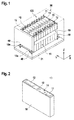
- Fig. 1 illustrates an exemplary embodiment of a conventional battery module 100 including a plurality of secondary battery cells 10 aligned in a row.
- a pair of end plates 18 are provided to face wide surfaces of the battery cells 10 at the outside of the battery cells 10, and a connection plate 19 is configured to connect the pair of end plates 18 to each other thereby fixing the plurality of battery cells 10 together.
- Fastening portions 18a on both sides of the battery module 100 are fastened to a support plate 31 by bolts 40.
- the support plate 31 is part of a housing 30.
- the battery module 100 further includes a bus bar 15 electrically connecting positive and negative electrode terminals of neighboring battery cells 10 and the bus bar 15 may be fixed by a nut 16 or the like.
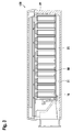
- each battery cell 10 is a prismatic (or rectangular) cell, the wide flat surfaces of the cells being stacked together to form the battery module.
- each battery cell 10 includes a battery case 18 configured for accommodation of an electrode assembly and an electrolyte.
- the battery case 18 is hermetically sealed by a cap assembly 14.
- the cap assembly 14 is provided with positive and negative electrode terminals 11 and 12 having different polarities, and a vent 13.
- the vent 13 is a safety means of the battery cell 10, which acts as a passage through which gas generated in the battery cell 10 is exhausted to the outside of the battery cell 10.
- the positive and negative electrode terminals 11 and 12 of neighboring battery cells 10 are electrically connected through a bus bar 15 as shown in Fig. 1 .
- the battery module 100 may be used as power source unit by electrically connecting the plurality of battery cells 10 as one bundle.
- Fig. 3 illustrates a schematic perspective view of a battery module 100 according to an embodiment of the present invention.
- a plurality of aligned battery cells 10 are arranged in the row and flow path plates 50 are disposed between adjacent battery cells 10.
- the battery module 100 further includes a first cooling channel 20 and a second cooling channel 40, which are aligned to the same side of the row.
- a coolant is introduced into an inlet of the first cooling channel 20 and flows towards an outlet of the second cooling channel 40.
- the coolant flows from the first cooling plate 20 into the flow path plate 50 and from the flow path plate 50 into the second cooling channel 40.
- the flow path plate 50 forms a cooling passage for the coolant from the inlet of the first cooling channel 20 towards the outlet of the second cooling channel 40. Cooling of the battery cells 10 is accomplished by the coolant passing the plate 50 disposed between the battery cells 10.
- the coolant may be air, but is not limited thereto.
- the battery module 100 may further include a housing 30 encompassing the battery module 100 and a support 31 as in the conventional battery module. As shown in Fig. 4 , the first cooling channel 20 and the second cooling channel 40 may be positioned at a bottom of the housing 30. Then, the bottom of the battery cells can be cooled by the coolant too.
- Fig. 5 is a perspective view of a flow path plate 50 according to an embodiment of the present invention.
- the flow path plate 50 includes an inlet 51 and an outlet 52 for the coolant.
- the inlet 51 of the plate 50 communicates with the first cooling channel 20 through a gap between the battery cell 10 and the plate 50 and thus, the coolant provided from the first cooling channel 20 is introduced through the inlet 51 into the plate 50.
- the coolant introduced into the inlet 51 of the plate 50 is guided by the guiding elements formed on the plate 50 and flows towards the outlet 52 of the plate 50.
- the outlet 52 of the plate 50 communicates with the second cooling channel 40 through a gap between the battery cell 10 and the plate 50 and thus, the coolant from the outlet 52 of the plate 50 flows towards the second cooling channel 40.
- the flow path plate 50 of the present invention may further include a side protrusion 53 and a lower supporting part 54 to be connected to the battery cell 10.
- the side protrusion 53 may be hinge-connected to the battery cell 10 and the lower supporting part 54 may be welded on the support 31 of the housing 30.
- the present invention is not limited thereto.
- the inlet 51 and the outlet 52 of the plate 50 may be positioned on a length side of the plate 50, which represents a preferred embodiment of the present invention.
- the length side is a side having a length longer than two other sides.
- the present invention is not limited thereto.
- the inlet 51 and the outlet 52 of the plate 50 may be arranged at any positions enabling to communicate with the first and second cooling channels, respectively.
- the guiding elements of the flow path plate 50 of the present invention include a plurality of curved ribs 62 and a plurality of circular elements 63.
- the curved ribs 62 and the circular elements 63 turn the coolant flow and cause turbulent flows.
- the turbulent flows improve the cooling performance.
- the circular elements 63 may be implemented as a circular disc or an oval disc.
- the circular elements 63 may be installed closed to the inlet 51 and/or outlet 52 of the plate 50. It may also improve the cooling efficiency.
- the plurality of curved ribs 62 and the plurality of circular elements 63 are connected via a netlike supporting structure 61.
- the term "netlike” means a structure having openings and connecting parts connecting the openings together. Due to the openings of the netlike supporting structure 61, the coolant passage for the coolant can be shared by both neighboring battery cells 10 and can cool front and rear surfaces of each of the battery cells 10.
- the battery module 100 may include a frame 55 encompassing the guiding elements and the guiding elements may include a central pin 64.
- the frame 55 and the central pin 64 provide the netlike structure of the plate 50 with mechanical stability.
- Fig. 5 illustrates that the central pin 64 extends from the bottom of the plate 50 towards the center of the plate 50.
- the center of the plate 50 may be a point at which the inlet 51 and outlet 52 meet.
- the central pin 64 preferably extends from the middle of the bottom of the plate 50 for improving mechanical stability and ensuring uniformly coolant flow on within the plate 50, but the present invention is not limited thereto.
- the central pin 64 can stably support the plate 50, it may extend from another point of the bottom, i.e., a point between the inlet 51 and the outlet 52 of the plate 50.
- the length of the central pin 64 is determined also to improve the stability of the plate 50 as well as to ensure uniform coolant distribution.
- the length of the central pin 64 is selected such that its length and the length of the bottom of the plate 50 are in range of 1:2 to 1.3.
- the central pin 64 may include a rounded tip 65 as shown in Fig. 5 . The rounded tip 65 can also cause turbulent flows.
- the guiding elements may be arranged mirror-symmetrical with respect to an axis subdividing the plate 50 into two parts of same dimension and extending from the side where the inlet 51 and the outlet 52 are positioned. Due to this symmetrical arrange of the guiding elements, the cooling length of one of the two parts of the plate 50 is equal to that of the other of the two parts of the plate 50. It assures an even distribution of coolant over the surface of the plate 50 and can improve the cooling efficiency.
- Fig. 6 schematically illustrates a perspective view of a flow path plate connected to a battery cell 10 according to an embodiment.
- a top of the plate 50 may be sealed by sealing material 70.
- the top may be a side of the plate 50 opposite to the side where the inlet 51 and outlet 52 of the plate 50 are positioned.
- the battery cell 10 includes the vent 13 as a safety means, which acts as a passage through which gas generated in the battery cell 10 is exhausted to the outside of the battery cell 10.
- the exhausted gas usually flows through a venting gas area and the venting gas area may be provided in the housing of the battery cell 10 and/or in a bus-bar 15 connecting the plurality of battery cells 10 together.
- the flow path plate 50 can be sealed from the venting gas area by the sealing material 70, which may improve the thermal stability.
- the sealing material 70 may be a non-conducting resin based sealant or a steel plate, but the present invention is not limited thereto.
- Fig. 7 illustrates a sectional view of a battery module 100 having a flow path plate 50 according to another embodiment.
- the plate 50 is installed between neighboring battery cells 10 aligned in the row as described above.
- the top of the plate 50 may be sealed by a sealing material 70 and a vent gas area 80 may be provided at the bus bar 15 connecting two battery cells 10.
- the cooling system provides a venting gas area above the battery cells, which is hermetically sealed from the cooling channels 20 and 40.
- a turbulent cooling passage having a long cooling length is evenly shared by both neighboring battery cells.
- a battery module having an improved cooling efficiency is provided.
- the coolant is evenly distributed on the plate.
Landscapes
- Chemical & Material Sciences (AREA)
- Chemical Kinetics & Catalysis (AREA)
- Electrochemistry (AREA)
- General Chemical & Material Sciences (AREA)
- Engineering & Computer Science (AREA)
- Manufacturing & Machinery (AREA)
- Inorganic Chemistry (AREA)
- Battery Mounting, Suspending (AREA)
- Secondary Cells (AREA)
Abstract
Description
- The present invention relates to a battery module having a cooling device and a vehicle comprising such battery module.
- A rechargeable or secondary battery differs from a primary battery in that it can be repeatedly charged and discharged, while the latter provides only an irreversible conversion of chemical to electrical energy. Low-capacity rechargeable batteries are used as power supply for small electronic devices, such as cellular phones, notebook computers and camcorders, while high-capacity rechargeable batteries are used as the power supply for hybrid vehicles and the like.
- In general, a rechargeable battery includes an electrode assembly including a positive electrode, a negative electrode, and a separator interposed between the positive and negative electrodes, a case receiving the electrode assembly, and an electrode terminal electrically connected to the electrode assembly. The case may have a cylindrical or rectangular shape depending on the intended purpose and the actual use of the rechargeable battery. An electrolyte solution is injected into the case for charging and discharging of the rechargeable battery through an electrochemical reaction of the positive electrode, the negative electrode, and the electrolyte solution.
- Rechargeable batteries may be used as a battery module formed of a plurality of unit battery cells coupled in series and/or in parallel so as to provide a high energy density, e.g. for motor driving of a hybrid vehicle. That is, the battery module is formed by interconnecting the electrode terminals of the plurality of unit battery cells depending on a required amount of power and in order to realize a high-power rechargeable battery, e.g. for an electric vehicle.
- In order to safely use these battery modules, heat generated from the rechargeable batteries should be efficiently emitted, discharged and/or dissipated. If there is insufficient heat emission/discharge/dissipation, a temperature deviation occurs between the respective battery cells, such that the battery module cannot generate the desired amount of power. In addition, when the internal temperature of the battery increases due to the heat generated from the rechargeable battery, abnormal reactions occurs therein and thus charging and discharging performance of the rechargeable battery deteriorates and the life-span of the rechargeable battery is shortened.
- Thus, cooling devices for cooling the rechargeable battery modules by efficiently emitting/discharging/dissipating heat generated from the battery are well-known in the art. One of well-known cooling devices is a cooling plate interposed between neighboring battery cells. Cooling plates according to the prior art usually include a closed surface having a cooling passage for a coolant. In that structure, the cooling passage is formed normally on only one surface of the cooling plate or both surfaces of each battery cell are unevenly cooled, which may lead to a low efficiency of cooling.
- It is thus an object of the present invention to overcome or reduce the drawback of the prior art and to provide a battery module having an improved cooling efficiency.
- A first aspect of the present invention relates to a battery module comprising: a plurality of secondary battery cells, a first cooling channel aligned to one side of the row and a second cooling channel aligned to the same side of the row; and a flow path plate installed between neighboring battery cells forming a cooling passage for a coolant from the first cooling channel towards the second cooling channel, the plate including a guiding structure configured to guide the coolant flow from an inlet of the plate, which communicates with the first cooling channel, to an outlet of the plate, which communicates with the second cooling channel. The guiding elements include a plurality of curved ribs and plurality of circular elements, which are connected via a netlike supporting structure.
- The battery module according to the cooling plate of the present invention has advantages in terms of the cooling efficiency. The curved ribs and the circular elements turn the coolant flow and cause turbulent flows. The turbulent flows minimize the volume of air flow while providing the maximum linear velocity at the surface. Thus, the turbulent flows generated around the curved ribs and the circular elements can improve the cooling performance. Further, since the plurality of curved ribs and the plurality of circular elements are connected via a netlike supporting structure, openings may be formed between the curved ribs and the circular elements. Then, the cooling passage for the coolant of the guiding elements may be evenly shared by both neighboring battery cells. It can evenly cool both of front and rear surfaces of each battery cell in the row, so that it can improve the cooling efficiency. In addition, the plurality of curved ribs and the plurality of circular elements may provide with a long cooling path, which can also improve the cooling efficiency. Further, the netlike structure may be less material consuming while providing a stable structure.
- According to a preferred embodiment of the present invention, the guiding elements may further include a central pin extending from a portion of the plate between the inlet and outlet towards a center of the plate. The central pin may provide the netlike structure of the cooling plate with mechanical stability. The central pin may have a first length and the plate may extend from the inlet towards the opposite side of the plate with a second length and a ratio of the first length to the second length may be in the range of 1:2 to 1:3. In this range, the stability may be optimized.
- Preferably, the central pin may have rounded tip and the circular elements may be installed closed to the inlet of the plate. These structures can enhance the turbulence of the flow of coolant and improve the efficiency of cooling.
- According to a preferred embodiment of the present invention, the inlet and the outlet may be arranged at a length side of the plate. This may elongate the cooling path.
- According to a preferred embodiment of the present invention, the battery module may include a housing and the first and second channels may be positioned at a bottom of the housing. This may improve the efficiency of cooling since also the bottom of the battery cells can be cooled by the coolant.
- According to a preferred embodiment of the present invention, the battery cells and the plate may have a prismatic shape and the guiding elements may be arranged mirror-symmetrical with respect to an axis subdividing the plate into two parts of same dimension and extending from the side where the inlet and the outlet are positioned. Due to this symmetrical arrange of the guiding elements, the cooling length of one of the two parts of the plate is equal to that of the other of the two parts of the plate. It assures an even distribution of coolant over the surface of the plate and can improve the cooling efficiency.
- Preferably, the battery module further comprises a frame encompassing the guiding elements. This may enhance the stability of the cooling plate.
- According to a preferred embodiment of the present invention, a top of the plate may be sealed by sealing material. This may improve the thermal stability since the cooling plate can be sealed from a venting gas area provided at the battery cell or the battery module. Preferably, the sealing material is a non-conductive resin-based sealant or a steel plate.
- According to a preferred embodiment of the present invention, the battery module may include a plurality of rows of secondary battery cells, which are aligned side by side in a column, and the plate may be installed between neighboring battery cells aligned in the row. This structure may reduce a volume of the battery module and simplify a manufacture thereof.
- According to another aspect of the present invention, a vehicle including a battery module as defined above is provided.
- Further aspects of the present invention could be learned from the dependent claims or the following description.
- Features will become apparent to those of ordinary skill in the art by describing in detail exemplary embodiments with reference to the attached drawings in which:
- Fig. 1
- illustrates an exemplary embodiment of a battery module;
- Fig. 2
- illustrates a schematic perspective view of a battery cell;
- Fig. 3
- illustrates a schematic of view of a battery module utilizing an active air-cooling approach according to an embodiment;
- Fig. 4
- illustrates a schematic perspective view of a housing supporting an active air-cooling approach according to an embodiment;
- Fig. 5
- illustrates a perspective view of a flow path plate according to an embodiment;
- Fig. 6
- illustrates a schematic perspective view of a flow path plate connected to a battery cell according to an embodiment; and
- Fig. 7
- illustrates a sectional view of a battery module having a flow path plate according to another embodiment.
- Reference will now be made in detail to embodiments, examples of which are illustrated in the accompanying drawings. Effects and features of the exemplary embodiments will be described with reference to the accompanying drawings. In the drawings, like reference numerals denote like elements, and redundant descriptions are omitted. Further, the use of "may" when describing embodiments of the present invention refers to "one or more embodiments of the present invention."
- It will be understood that although the terms "first" and "second" are used to describe various elements, these elements should not be limited by these terms. These terms are only used to distinguish one element from another element. For example, a first element may be named a second element and, similarly, a second element may be named a first element, without departing from the scope of the present invention.
- In the following description of embodiments of the present invention, the terms of a singular form may include plural forms unless the context clearly indicates otherwise.
- It will be further understood that the terms "include," "comprise," "including," or "comprising" specify a property, a region, a fixed number, a step, a process, an element, a component, and a combination thereof but do not exclude other properties, regions, fixed numbers, steps, processes, elements, components, and combinations thereof.
- It will also be understood that when a film, a region, or an element is referred to as being "above" or "on" another film, region, or element, it can be directly on the other film, region, or element, or intervening films, regions, or elements may also be present.
- It will be understood that when an element or layer is referred to as being "on," "connected to," or "coupled to" another element or layer, it can be directly on, connected to, or coupled to the other element or layer, or one or more intervening elements or layers may be present. In addition, it will also be understood that when an element or layer is referred to as being "between" two elements or layers, it can be the only element or layer between the two elements or layers, or one or more intervening elements or layers may also be present.
- Unless otherwise defined, all terms (including technical and scientific terms) used herein have the same meaning as commonly understood by one of ordinary skill in the art to which the present invention belongs. It will be further understood that terms, such as those defined in commonly used dictionaries, should be interpreted as having a meaning that is consistent with their meaning in the context of the relevant art and/or the present specification, and should not be interpreted in an idealized or overly formal sense, unless expressly so defined herein.
-
Fig. 1 illustrates an exemplary embodiment of aconventional battery module 100 including a plurality ofsecondary battery cells 10 aligned in a row. A pair ofend plates 18 are provided to face wide surfaces of thebattery cells 10 at the outside of thebattery cells 10, and aconnection plate 19 is configured to connect the pair ofend plates 18 to each other thereby fixing the plurality ofbattery cells 10 together.Fastening portions 18a on both sides of thebattery module 100 are fastened to asupport plate 31 bybolts 40. Thesupport plate 31 is part of ahousing 30. Thebattery module 100 further includes abus bar 15 electrically connecting positive and negative electrode terminals of neighboringbattery cells 10 and thebus bar 15 may be fixed by anut 16 or the like. - Referring to
Fig. 2 , eachbattery cell 10 is a prismatic (or rectangular) cell, the wide flat surfaces of the cells being stacked together to form the battery module. Further, eachbattery cell 10 includes abattery case 18 configured for accommodation of an electrode assembly and an electrolyte. Thebattery case 18 is hermetically sealed by acap assembly 14. Thecap assembly 14 is provided with positive andnegative electrode terminals vent 13. Thevent 13 is a safety means of thebattery cell 10, which acts as a passage through which gas generated in thebattery cell 10 is exhausted to the outside of thebattery cell 10. The positive andnegative electrode terminals battery cells 10 are electrically connected through abus bar 15 as shown inFig. 1 . Hence, thebattery module 100 may be used as power source unit by electrically connecting the plurality ofbattery cells 10 as one bundle. -
Fig. 3 illustrates a schematic perspective view of abattery module 100 according to an embodiment of the present invention. A plurality of alignedbattery cells 10 are arranged in the row and flowpath plates 50 are disposed betweenadjacent battery cells 10. Thebattery module 100 further includes afirst cooling channel 20 and asecond cooling channel 40, which are aligned to the same side of the row. As shown inFig. 3 , a coolant is introduced into an inlet of thefirst cooling channel 20 and flows towards an outlet of thesecond cooling channel 40. Specifically, the coolant flows from thefirst cooling plate 20 into theflow path plate 50 and from theflow path plate 50 into thesecond cooling channel 40. Thus, theflow path plate 50 forms a cooling passage for the coolant from the inlet of thefirst cooling channel 20 towards the outlet of thesecond cooling channel 40. Cooling of thebattery cells 10 is accomplished by the coolant passing theplate 50 disposed between thebattery cells 10. The coolant may be air, but is not limited thereto. - The
battery module 100 may further include ahousing 30 encompassing thebattery module 100 and asupport 31 as in the conventional battery module. As shown inFig. 4 , thefirst cooling channel 20 and thesecond cooling channel 40 may be positioned at a bottom of thehousing 30. Then, the bottom of the battery cells can be cooled by the coolant too. -
Fig. 5 is a perspective view of aflow path plate 50 according to an embodiment of the present invention. As shown inFig. 5 , theflow path plate 50 includes aninlet 51 and anoutlet 52 for the coolant. Theinlet 51 of theplate 50 communicates with thefirst cooling channel 20 through a gap between thebattery cell 10 and theplate 50 and thus, the coolant provided from thefirst cooling channel 20 is introduced through theinlet 51 into theplate 50. As shown inFig. 5 , the coolant introduced into theinlet 51 of theplate 50 is guided by the guiding elements formed on theplate 50 and flows towards theoutlet 52 of theplate 50. Theoutlet 52 of theplate 50 communicates with thesecond cooling channel 40 through a gap between thebattery cell 10 and theplate 50 and thus, the coolant from theoutlet 52 of theplate 50 flows towards thesecond cooling channel 40. - The
flow path plate 50 of the present invention may further include aside protrusion 53 and a lower supportingpart 54 to be connected to thebattery cell 10. Theside protrusion 53 may be hinge-connected to thebattery cell 10 and the lower supportingpart 54 may be welded on thesupport 31 of thehousing 30. However, the present invention is not limited thereto. - The
inlet 51 and theoutlet 52 of theplate 50 may be positioned on a length side of theplate 50, which represents a preferred embodiment of the present invention. Here, the length side is a side having a length longer than two other sides. However, the present invention is not limited thereto. Theinlet 51 and theoutlet 52 of theplate 50 may be arranged at any positions enabling to communicate with the first and second cooling channels, respectively. - Referring to
Fig. 5 , the guiding elements of theflow path plate 50 of the present invention include a plurality ofcurved ribs 62 and a plurality ofcircular elements 63. Thecurved ribs 62 and thecircular elements 63 turn the coolant flow and cause turbulent flows. As well-known, the turbulent flows improve the cooling performance. Thus, all kind of shapes of ribs and circular elements enabling to turn the coolant flow may be applied to theflow path plate 50 of the present invention. For example, thecircular elements 63 may be implemented as a circular disc or an oval disc. Here, thecircular elements 63 may be installed closed to theinlet 51 and/oroutlet 52 of theplate 50. It may also improve the cooling efficiency. - As further shown in
Fig. 5 , the plurality ofcurved ribs 62 and the plurality ofcircular elements 63 are connected via anetlike supporting structure 61. The term "netlike" means a structure having openings and connecting parts connecting the openings together. Due to the openings of thenetlike supporting structure 61, the coolant passage for the coolant can be shared by both neighboringbattery cells 10 and can cool front and rear surfaces of each of thebattery cells 10. - As shown in
Fig. 5 , thebattery module 100 according to the present invention may include aframe 55 encompassing the guiding elements and the guiding elements may include acentral pin 64. Theframe 55 and thecentral pin 64 provide the netlike structure of theplate 50 with mechanical stability.Fig. 5 illustrates that thecentral pin 64 extends from the bottom of theplate 50 towards the center of theplate 50. Here, the center of theplate 50 may be a point at which theinlet 51 andoutlet 52 meet. Thecentral pin 64 preferably extends from the middle of the bottom of theplate 50 for improving mechanical stability and ensuring uniformly coolant flow on within theplate 50, but the present invention is not limited thereto. As long as thecentral pin 64 can stably support theplate 50, it may extend from another point of the bottom, i.e., a point between theinlet 51 and theoutlet 52 of theplate 50. The length of thecentral pin 64 is determined also to improve the stability of theplate 50 as well as to ensure uniform coolant distribution. Preferably, the length of thecentral pin 64 is selected such that its length and the length of the bottom of theplate 50 are in range of 1:2 to 1.3. Thecentral pin 64 may include arounded tip 65 as shown inFig. 5 . The roundedtip 65 can also cause turbulent flows. - The guiding elements may be arranged mirror-symmetrical with respect to an axis subdividing the
plate 50 into two parts of same dimension and extending from the side where theinlet 51 and theoutlet 52 are positioned. Due to this symmetrical arrange of the guiding elements, the cooling length of one of the two parts of theplate 50 is equal to that of the other of the two parts of theplate 50. It assures an even distribution of coolant over the surface of theplate 50 and can improve the cooling efficiency. -
Fig. 6 schematically illustrates a perspective view of a flow path plate connected to abattery cell 10 according to an embodiment. As shown inFig. 6 , a top of theplate 50 may be sealed by sealingmaterial 70. Here, the top may be a side of theplate 50 opposite to the side where theinlet 51 andoutlet 52 of theplate 50 are positioned. As described above, thebattery cell 10 includes thevent 13 as a safety means, which acts as a passage through which gas generated in thebattery cell 10 is exhausted to the outside of thebattery cell 10. The exhausted gas usually flows through a venting gas area and the venting gas area may be provided in the housing of thebattery cell 10 and/or in a bus-bar 15 connecting the plurality ofbattery cells 10 together. According to the present invention, theflow path plate 50 can be sealed from the venting gas area by the sealingmaterial 70, which may improve the thermal stability. The sealingmaterial 70 may be a non-conducting resin based sealant or a steel plate, but the present invention is not limited thereto. -
Fig. 7 illustrates a sectional view of abattery module 100 having aflow path plate 50 according to another embodiment. Theplate 50 is installed between neighboringbattery cells 10 aligned in the row as described above. Also in this embodiment, the top of theplate 50 may be sealed by a sealingmaterial 70 and avent gas area 80 may be provided at thebus bar 15 connecting twobattery cells 10. In terms of high thermal stress thesecondary battery cell 10 may rupture and a significant amount of flammable and hazardous gas may occur. In case of automotive application, it has to be assured that the gas is not entering the vehicle compartment. In order to achieve this goal, the cooling system provides a venting gas area above the battery cells, which is hermetically sealed from the coolingchannels - According to the present invention, a turbulent cooling passage having a long cooling length is evenly shared by both neighboring battery cells. Thus, a battery module having an improved cooling efficiency is provided. Further, due to the symmetrical arrangement of the cooling passage on the flow path plate, the coolant is evenly distributed on the plate.
Claims (14)
- A battery module (100) including:- a plurality of secondary battery cells (10) aligned in a row;- a first cooling channel (20) aligned to one side of the row and a second cooling channel (40) aligned to the same side of the row; and- a flow path plate (50) installed between neighboring battery cells (10) forming a cooling passage for a coolant from the first cooling channel (20) towards the second cooling channel (40), the plate (50) including guiding elements configured to guide the coolant flow from an inlet (51) of the plate (50), which communicates with the first cooling channel (20), to an outlet (52) of the plate (50), which communicates with the second cooling channel (40),wherein the guiding elements include a plurality of curved ribs (62) and plurality of circular elements (63), which are connected via a netlike supporting structure (61).
- The battery module of claim 1, wherein the guiding elements further include a central pin (64) extending from a portion of the plate (50) between the inlet (51) and outlet (52) of the plate (50) towards a center of the plate (50).
- The battery module of claim 2, wherein the central pin (64) has a rounded tip (65).
- The battery module of claim 2 or 3, wherein the central pin (64) has a first length and the plate (50) extends from the inlet (51) of the plate (50) towards the opposite side of the plate (50) with a second length and a ratio of the first length to the second length is in the range of 1:2 to 1:3.
- The battery module of one of the preceding claims, wherein the circular elements (63) are installed closed to the inlet and/or the outlet of the plate (50).
- The battery module of one of the preceding claims, wherein the inlet (51) of the plate (50) and the outlet (52) of the plate (52) are arranged at a length side of the plate (50).
- The battery module of one of the preceding claims, wherein the battery module (100) includes a housing (30) and the first and second channels (20, 40) are positioned at a bottom of the housing (30).
- The battery module of one of the preceding claims, wherein the battery cells (10) and the plate (50) have a prismatic shape.
- The battery module of claim 8, wherein the guiding elements are arranged mirror-symmetrical with respect to an axis subdividing the plate (50) into two parts of same dimension and extending from the side where the inlet (51) of the plate (50) and the outlet (52) of the plate (50) are positioned.
- The battery module of one of the preceding claims, further comprising a frame (55) encompassing the plate (50).
- The battery module of one of the preceding claims, wherein a top of the plate (50) is sealed by sealing material (70).
- The battery module of claim 11, the sealing material (70) is a non-conducting resin based sealant or a steel plate.
- The battery module of claim 11, further comprising a vent gas area (80) on the sealing material.
- A vehicle including a battery module (100) according to one of the preceding claims.
Priority Applications (5)
| Application Number | Priority Date | Filing Date | Title |
|---|---|---|---|
| EP16195786.5A EP3316340B1 (en) | 2016-10-26 | 2016-10-26 | Battery module |
| KR1020170139409A KR102195583B1 (en) | 2016-10-26 | 2017-10-25 | Battery module |
| PCT/KR2017/011884 WO2018080182A1 (en) | 2016-10-26 | 2017-10-26 | Battery module |
| CN201780066216.XA CN109891666B (en) | 2016-10-26 | 2017-10-26 | Battery module |
| US16/342,501 US20190260102A1 (en) | 2016-10-26 | 2017-10-26 | Battery module |
Applications Claiming Priority (1)
| Application Number | Priority Date | Filing Date | Title |
|---|---|---|---|
| EP16195786.5A EP3316340B1 (en) | 2016-10-26 | 2016-10-26 | Battery module |
Publications (2)
| Publication Number | Publication Date |
|---|---|
| EP3316340A1 true EP3316340A1 (en) | 2018-05-02 |
| EP3316340B1 EP3316340B1 (en) | 2019-03-13 |
Family
ID=57206160
Family Applications (1)
| Application Number | Title | Priority Date | Filing Date |
|---|---|---|---|
| EP16195786.5A Active EP3316340B1 (en) | 2016-10-26 | 2016-10-26 | Battery module |
Country Status (3)
| Country | Link |
|---|---|
| US (1) | US20190260102A1 (en) |
| EP (1) | EP3316340B1 (en) |
| KR (1) | KR102195583B1 (en) |
Cited By (11)
| Publication number | Priority date | Publication date | Assignee | Title |
|---|---|---|---|---|
| CN110783660A (en) * | 2018-07-27 | 2020-02-11 | 马勒国际有限公司 | Accumulator device |
| CN110783659A (en) * | 2018-07-27 | 2020-02-11 | 马勒国际有限公司 | Accumulator device |
| CN111435760A (en) * | 2019-12-26 | 2020-07-21 | 蜂巢能源科技有限公司 | Stacking method, stacking tool and battery module of battery module |
| JP2021504888A (en) * | 2018-06-08 | 2021-02-15 | エルジー・ケム・リミテッド | Battery module with improved cooling structure |
| DE102021201596A1 (en) | 2021-02-19 | 2022-08-25 | Mahle International Gmbh | Cooling frame for a battery cell arrangement |
| US11616265B2 (en) | 2018-10-19 | 2023-03-28 | Samsung Sdi Co., Ltd. | Battery module |
| US11626630B2 (en) | 2018-10-19 | 2023-04-11 | Samsung Sdi Co., Ltd. | Battery module |
| US11637339B2 (en) | 2018-10-19 | 2023-04-25 | Samsung Sdi Co., Ltd. | Battery module |
| US11862778B2 (en) | 2018-10-19 | 2024-01-02 | Samsung Sdi Co., Ltd. | Battery module |
| US11876243B2 (en) | 2018-10-19 | 2024-01-16 | Samsung Sdi Co., Ltd. | Battery module |
| US11901529B2 (en) | 2018-10-19 | 2024-02-13 | Samsung Sdi Co., Ltd. | Battery module |
Families Citing this family (7)
| Publication number | Priority date | Publication date | Assignee | Title |
|---|---|---|---|---|
| KR102331723B1 (en) | 2017-03-21 | 2021-11-26 | 삼성에스디아이 주식회사 | colling apparatus for battery pack |
| US12107248B2 (en) | 2020-03-31 | 2024-10-01 | Samsung Sdi Co., Ltd. | Robust interface for cooler to housing |
| CN113889686A (en) * | 2020-07-03 | 2022-01-04 | 恒大新能源技术(深圳)有限公司 | Battery modules, battery packs and vehicles |
| CN112687982B (en) * | 2020-12-28 | 2022-04-12 | 合肥国轩高科动力能源有限公司 | Battery cooling module |
| US12096594B2 (en) * | 2021-09-23 | 2024-09-17 | The Esab Group Inc. | Fluidic routing structures for liquid cooling of power modules of power supplies |
| WO2024139230A1 (en) * | 2022-12-30 | 2024-07-04 | 湖北亿纬动力有限公司 | Battery module and battery pack provided with battery module |
| US12476322B2 (en) | 2023-10-10 | 2025-11-18 | Ford Global Technologies, Llc | Battery pack venting assembly and venting method |
Citations (4)
| Publication number | Priority date | Publication date | Assignee | Title |
|---|---|---|---|---|
| US20060115720A1 (en) * | 2004-11-30 | 2006-06-01 | Kim Tae-Yong | Battery module |
| US20120064386A1 (en) * | 2010-09-14 | 2012-03-15 | Honda Motor Co., Ltd. | Battery module |
| US20120208064A1 (en) * | 2010-11-01 | 2012-08-16 | Toyota Jidosha Kabushiki Kaisha | Electric storage apparatus |
| US20120308868A1 (en) * | 2011-05-31 | 2012-12-06 | Delphi Tecnologies, Inc. | Battery arrangement |
Family Cites Families (7)
| Publication number | Priority date | Publication date | Assignee | Title |
|---|---|---|---|---|
| KR20060102851A (en) * | 2005-03-25 | 2006-09-28 | 삼성에스디아이 주식회사 | Secondary battery module |
| DE102011011238A1 (en) * | 2011-02-15 | 2012-08-16 | Li-Tec Battery Gmbh | Housing for receiving a flat electrochemical cell |
| US9847561B2 (en) * | 2014-06-20 | 2017-12-19 | GM Global Technology Operations LLC | Cell cooling frames with cantilevered side seals |
| JP6112095B2 (en) * | 2014-10-30 | 2017-04-12 | トヨタ自動車株式会社 | Temperature control structure of power storage device |
| KR101748360B1 (en) * | 2014-12-01 | 2017-06-16 | 주식회사 엘지화학 | Battery Module |
| US20160336549A1 (en) * | 2015-05-11 | 2016-11-17 | GM Global Technology Operations LLC | Rigid battery module frame of polymeric material |
| KR101947887B1 (en) * | 2017-01-03 | 2019-02-13 | 삼성에스디아이 주식회사 | Battery pack housing |
-
2016
- 2016-10-26 EP EP16195786.5A patent/EP3316340B1/en active Active
-
2017
- 2017-10-25 KR KR1020170139409A patent/KR102195583B1/en active Active
- 2017-10-26 US US16/342,501 patent/US20190260102A1/en not_active Abandoned
Patent Citations (4)
| Publication number | Priority date | Publication date | Assignee | Title |
|---|---|---|---|---|
| US20060115720A1 (en) * | 2004-11-30 | 2006-06-01 | Kim Tae-Yong | Battery module |
| US20120064386A1 (en) * | 2010-09-14 | 2012-03-15 | Honda Motor Co., Ltd. | Battery module |
| US20120208064A1 (en) * | 2010-11-01 | 2012-08-16 | Toyota Jidosha Kabushiki Kaisha | Electric storage apparatus |
| US20120308868A1 (en) * | 2011-05-31 | 2012-12-06 | Delphi Tecnologies, Inc. | Battery arrangement |
Cited By (17)
| Publication number | Priority date | Publication date | Assignee | Title |
|---|---|---|---|---|
| JP7082665B2 (en) | 2018-06-08 | 2022-06-08 | エルジー エナジー ソリューション リミテッド | Battery module with improved cooling structure |
| JP2021504888A (en) * | 2018-06-08 | 2021-02-15 | エルジー・ケム・リミテッド | Battery module with improved cooling structure |
| CN110783659A (en) * | 2018-07-27 | 2020-02-11 | 马勒国际有限公司 | Accumulator device |
| CN110783660A (en) * | 2018-07-27 | 2020-02-11 | 马勒国际有限公司 | Accumulator device |
| US11901529B2 (en) | 2018-10-19 | 2024-02-13 | Samsung Sdi Co., Ltd. | Battery module |
| US11616265B2 (en) | 2018-10-19 | 2023-03-28 | Samsung Sdi Co., Ltd. | Battery module |
| US11626630B2 (en) | 2018-10-19 | 2023-04-11 | Samsung Sdi Co., Ltd. | Battery module |
| US11637339B2 (en) | 2018-10-19 | 2023-04-25 | Samsung Sdi Co., Ltd. | Battery module |
| US11862778B2 (en) | 2018-10-19 | 2024-01-02 | Samsung Sdi Co., Ltd. | Battery module |
| US11876243B2 (en) | 2018-10-19 | 2024-01-16 | Samsung Sdi Co., Ltd. | Battery module |
| US12046735B2 (en) | 2018-10-19 | 2024-07-23 | Samsung Sdi Co., Ltd. | Battery module |
| US12288860B2 (en) | 2018-10-19 | 2025-04-29 | Samsung Sdi Co., Ltd. | Battery module |
| US12362409B2 (en) | 2018-10-19 | 2025-07-15 | Samsung Sdi Co., Ltd. | Battery module |
| US12412946B2 (en) | 2018-10-19 | 2025-09-09 | Samsung Sdi Co., Ltd. | Battery module |
| CN111435760B (en) * | 2019-12-26 | 2022-05-27 | 蜂巢能源科技有限公司 | Stacking method, stacking tool and battery module of battery module |
| CN111435760A (en) * | 2019-12-26 | 2020-07-21 | 蜂巢能源科技有限公司 | Stacking method, stacking tool and battery module of battery module |
| DE102021201596A1 (en) | 2021-02-19 | 2022-08-25 | Mahle International Gmbh | Cooling frame for a battery cell arrangement |
Also Published As
| Publication number | Publication date |
|---|---|
| KR20180045840A (en) | 2018-05-04 |
| KR102195583B1 (en) | 2020-12-29 |
| EP3316340B1 (en) | 2019-03-13 |
| US20190260102A1 (en) | 2019-08-22 |
Similar Documents
| Publication | Publication Date | Title |
|---|---|---|
| EP3316340B1 (en) | Battery module | |
| US20240213579A1 (en) | Battery pack comprising frame profile having integral refrigerant circuit member | |
| KR102029407B1 (en) | Battery system | |
| EP3780250B1 (en) | Battery module, battery pack comprising same battery module, and vehicle comprising same battery pack | |
| KR102259217B1 (en) | Battery System and Vehicle Comprising the Same | |
| EP3157092B1 (en) | Battery module including a cooling plate with embedded cooling tubes | |
| EP3154103B1 (en) | Battery module including a housing floor with integrated cooling | |
| EP3319146B1 (en) | Battery system | |
| EP3482429B1 (en) | Battery system and vehicle | |
| CN109845024B (en) | Battery system and electric vehicle including the same | |
| KR101282519B1 (en) | Battery module | |
| CN109891666B (en) | Battery module | |
| US11139521B2 (en) | Battery submodule carrier, battery submodule, battery system and vehicle | |
| US8852773B2 (en) | Battery pack | |
| US8835036B2 (en) | Battery pack | |
| US20120129030A1 (en) | Battery Pack | |
| EP3309858A1 (en) | Battery module carrier, battery system and use of a modified h-beam as battery module carrier | |
| KR102061292B1 (en) | Battery module, battery pack comprising the battery module and vehicle comprising the battery pack | |
| EP3772122B1 (en) | Battery module with a multifunctional end-plate | |
| EP3637537A1 (en) | Bypass tube for a cooling circuit of a vehicle battery pack | |
| CN120693724A (en) | Battery packaging | |
| KR20240097668A (en) | Battery pack | |
| EP3522292A1 (en) | Fluid connector for a battery pack of a vehicle, and battery pack for a vehicle | |
| US20250372759A1 (en) | Battery Pack |
Legal Events
| Date | Code | Title | Description |
|---|---|---|---|
| PUAI | Public reference made under article 153(3) epc to a published international application that has entered the european phase |
Free format text: ORIGINAL CODE: 0009012 |
|
| STAA | Information on the status of an ep patent application or granted ep patent |
Free format text: STATUS: REQUEST FOR EXAMINATION WAS MADE |
|
| 17P | Request for examination filed |
Effective date: 20170703 |
|
| AK | Designated contracting states |
Kind code of ref document: A1 Designated state(s): AL AT BE BG CH CY CZ DE DK EE ES FI FR GB GR HR HU IE IS IT LI LT LU LV MC MK MT NL NO PL PT RO RS SE SI SK SM TR |
|
| AX | Request for extension of the european patent |
Extension state: BA ME |
|
| GRAP | Despatch of communication of intention to grant a patent |
Free format text: ORIGINAL CODE: EPIDOSNIGR1 |
|
| STAA | Information on the status of an ep patent application or granted ep patent |
Free format text: STATUS: GRANT OF PATENT IS INTENDED |
|
| INTG | Intention to grant announced |
Effective date: 20181102 |
|
| GRAS | Grant fee paid |
Free format text: ORIGINAL CODE: EPIDOSNIGR3 |
|
| GRAA | (expected) grant |
Free format text: ORIGINAL CODE: 0009210 |
|
| STAA | Information on the status of an ep patent application or granted ep patent |
Free format text: STATUS: THE PATENT HAS BEEN GRANTED |
|
| AK | Designated contracting states |
Kind code of ref document: B1 Designated state(s): AL AT BE BG CH CY CZ DE DK EE ES FI FR GB GR HR HU IE IS IT LI LT LU LV MC MK MT NL NO PL PT RO RS SE SI SK SM TR |
|
| REG | Reference to a national code |
Ref country code: GB Ref legal event code: FG4D |
|
| REG | Reference to a national code |
Ref country code: CH Ref legal event code: EP Ref country code: AT Ref legal event code: REF Ref document number: 1108917 Country of ref document: AT Kind code of ref document: T Effective date: 20190315 |
|
| REG | Reference to a national code |
Ref country code: IE Ref legal event code: FG4D |
|
| REG | Reference to a national code |
Ref country code: DE Ref legal event code: R096 Ref document number: 602016010966 Country of ref document: DE |
|
| REG | Reference to a national code |
Ref country code: NL Ref legal event code: MP Effective date: 20190313 |
|
| REG | Reference to a national code |
Ref country code: LT Ref legal event code: MG4D |
|
| PG25 | Lapsed in a contracting state [announced via postgrant information from national office to epo] |
Ref country code: SE Free format text: LAPSE BECAUSE OF FAILURE TO SUBMIT A TRANSLATION OF THE DESCRIPTION OR TO PAY THE FEE WITHIN THE PRESCRIBED TIME-LIMIT Effective date: 20190313 Ref country code: FI Free format text: LAPSE BECAUSE OF FAILURE TO SUBMIT A TRANSLATION OF THE DESCRIPTION OR TO PAY THE FEE WITHIN THE PRESCRIBED TIME-LIMIT Effective date: 20190313 Ref country code: NO Free format text: LAPSE BECAUSE OF FAILURE TO SUBMIT A TRANSLATION OF THE DESCRIPTION OR TO PAY THE FEE WITHIN THE PRESCRIBED TIME-LIMIT Effective date: 20190613 Ref country code: LT Free format text: LAPSE BECAUSE OF FAILURE TO SUBMIT A TRANSLATION OF THE DESCRIPTION OR TO PAY THE FEE WITHIN THE PRESCRIBED TIME-LIMIT Effective date: 20190313 |
|
| PG25 | Lapsed in a contracting state [announced via postgrant information from national office to epo] |
Ref country code: GR Free format text: LAPSE BECAUSE OF FAILURE TO SUBMIT A TRANSLATION OF THE DESCRIPTION OR TO PAY THE FEE WITHIN THE PRESCRIBED TIME-LIMIT Effective date: 20190614 Ref country code: BG Free format text: LAPSE BECAUSE OF FAILURE TO SUBMIT A TRANSLATION OF THE DESCRIPTION OR TO PAY THE FEE WITHIN THE PRESCRIBED TIME-LIMIT Effective date: 20190613 Ref country code: HR Free format text: LAPSE BECAUSE OF FAILURE TO SUBMIT A TRANSLATION OF THE DESCRIPTION OR TO PAY THE FEE WITHIN THE PRESCRIBED TIME-LIMIT Effective date: 20190313 Ref country code: NL Free format text: LAPSE BECAUSE OF FAILURE TO SUBMIT A TRANSLATION OF THE DESCRIPTION OR TO PAY THE FEE WITHIN THE PRESCRIBED TIME-LIMIT Effective date: 20190313 Ref country code: RS Free format text: LAPSE BECAUSE OF FAILURE TO SUBMIT A TRANSLATION OF THE DESCRIPTION OR TO PAY THE FEE WITHIN THE PRESCRIBED TIME-LIMIT Effective date: 20190313 Ref country code: LV Free format text: LAPSE BECAUSE OF FAILURE TO SUBMIT A TRANSLATION OF THE DESCRIPTION OR TO PAY THE FEE WITHIN THE PRESCRIBED TIME-LIMIT Effective date: 20190313 |
|
| PG25 | Lapsed in a contracting state [announced via postgrant information from national office to epo] |
Ref country code: SK Free format text: LAPSE BECAUSE OF FAILURE TO SUBMIT A TRANSLATION OF THE DESCRIPTION OR TO PAY THE FEE WITHIN THE PRESCRIBED TIME-LIMIT Effective date: 20190313 Ref country code: RO Free format text: LAPSE BECAUSE OF FAILURE TO SUBMIT A TRANSLATION OF THE DESCRIPTION OR TO PAY THE FEE WITHIN THE PRESCRIBED TIME-LIMIT Effective date: 20190313 Ref country code: CZ Free format text: LAPSE BECAUSE OF FAILURE TO SUBMIT A TRANSLATION OF THE DESCRIPTION OR TO PAY THE FEE WITHIN THE PRESCRIBED TIME-LIMIT Effective date: 20190313 Ref country code: EE Free format text: LAPSE BECAUSE OF FAILURE TO SUBMIT A TRANSLATION OF THE DESCRIPTION OR TO PAY THE FEE WITHIN THE PRESCRIBED TIME-LIMIT Effective date: 20190313 Ref country code: IT Free format text: LAPSE BECAUSE OF FAILURE TO SUBMIT A TRANSLATION OF THE DESCRIPTION OR TO PAY THE FEE WITHIN THE PRESCRIBED TIME-LIMIT Effective date: 20190313 Ref country code: ES Free format text: LAPSE BECAUSE OF FAILURE TO SUBMIT A TRANSLATION OF THE DESCRIPTION OR TO PAY THE FEE WITHIN THE PRESCRIBED TIME-LIMIT Effective date: 20190313 Ref country code: AL Free format text: LAPSE BECAUSE OF FAILURE TO SUBMIT A TRANSLATION OF THE DESCRIPTION OR TO PAY THE FEE WITHIN THE PRESCRIBED TIME-LIMIT Effective date: 20190313 Ref country code: PT Free format text: LAPSE BECAUSE OF FAILURE TO SUBMIT A TRANSLATION OF THE DESCRIPTION OR TO PAY THE FEE WITHIN THE PRESCRIBED TIME-LIMIT Effective date: 20190713 |
|
| PG25 | Lapsed in a contracting state [announced via postgrant information from national office to epo] |
Ref country code: SM Free format text: LAPSE BECAUSE OF FAILURE TO SUBMIT A TRANSLATION OF THE DESCRIPTION OR TO PAY THE FEE WITHIN THE PRESCRIBED TIME-LIMIT Effective date: 20190313 Ref country code: PL Free format text: LAPSE BECAUSE OF FAILURE TO SUBMIT A TRANSLATION OF THE DESCRIPTION OR TO PAY THE FEE WITHIN THE PRESCRIBED TIME-LIMIT Effective date: 20190313 |
|
| REG | Reference to a national code |
Ref country code: DE Ref legal event code: R097 Ref document number: 602016010966 Country of ref document: DE |
|
| PG25 | Lapsed in a contracting state [announced via postgrant information from national office to epo] |
Ref country code: IS Free format text: LAPSE BECAUSE OF FAILURE TO SUBMIT A TRANSLATION OF THE DESCRIPTION OR TO PAY THE FEE WITHIN THE PRESCRIBED TIME-LIMIT Effective date: 20190713 |
|
| PLBE | No opposition filed within time limit |
Free format text: ORIGINAL CODE: 0009261 |
|
| STAA | Information on the status of an ep patent application or granted ep patent |
Free format text: STATUS: NO OPPOSITION FILED WITHIN TIME LIMIT |
|
| PG25 | Lapsed in a contracting state [announced via postgrant information from national office to epo] |
Ref country code: DK Free format text: LAPSE BECAUSE OF FAILURE TO SUBMIT A TRANSLATION OF THE DESCRIPTION OR TO PAY THE FEE WITHIN THE PRESCRIBED TIME-LIMIT Effective date: 20190313 |
|
| 26N | No opposition filed |
Effective date: 20191216 |
|
| PG25 | Lapsed in a contracting state [announced via postgrant information from national office to epo] |
Ref country code: TR Free format text: LAPSE BECAUSE OF FAILURE TO SUBMIT A TRANSLATION OF THE DESCRIPTION OR TO PAY THE FEE WITHIN THE PRESCRIBED TIME-LIMIT Effective date: 20190313 |
|
| PG25 | Lapsed in a contracting state [announced via postgrant information from national office to epo] |
Ref country code: MC Free format text: LAPSE BECAUSE OF FAILURE TO SUBMIT A TRANSLATION OF THE DESCRIPTION OR TO PAY THE FEE WITHIN THE PRESCRIBED TIME-LIMIT Effective date: 20190313 |
|
| REG | Reference to a national code |
Ref country code: CH Ref legal event code: PL |
|
| PG25 | Lapsed in a contracting state [announced via postgrant information from national office to epo] |
Ref country code: LI Free format text: LAPSE BECAUSE OF NON-PAYMENT OF DUE FEES Effective date: 20191031 Ref country code: CH Free format text: LAPSE BECAUSE OF NON-PAYMENT OF DUE FEES Effective date: 20191031 Ref country code: LU Free format text: LAPSE BECAUSE OF NON-PAYMENT OF DUE FEES Effective date: 20191026 |
|
| REG | Reference to a national code |
Ref country code: BE Ref legal event code: MM Effective date: 20191031 |
|
| PG25 | Lapsed in a contracting state [announced via postgrant information from national office to epo] |
Ref country code: BE Free format text: LAPSE BECAUSE OF NON-PAYMENT OF DUE FEES Effective date: 20191031 |
|
| PG25 | Lapsed in a contracting state [announced via postgrant information from national office to epo] |
Ref country code: IE Free format text: LAPSE BECAUSE OF NON-PAYMENT OF DUE FEES Effective date: 20191026 |
|
| REG | Reference to a national code |
Ref country code: DE Ref legal event code: R079 Ref document number: 602016010966 Country of ref document: DE Free format text: PREVIOUS MAIN CLASS: H01M0002100000 Ipc: H01M0050200000 |
|
| PG25 | Lapsed in a contracting state [announced via postgrant information from national office to epo] |
Ref country code: CY Free format text: LAPSE BECAUSE OF FAILURE TO SUBMIT A TRANSLATION OF THE DESCRIPTION OR TO PAY THE FEE WITHIN THE PRESCRIBED TIME-LIMIT Effective date: 20190313 |
|
| REG | Reference to a national code |
Ref country code: AT Ref legal event code: UEP Ref document number: 1108917 Country of ref document: AT Kind code of ref document: T Effective date: 20190313 |
|
| PG25 | Lapsed in a contracting state [announced via postgrant information from national office to epo] |
Ref country code: HU Free format text: LAPSE BECAUSE OF FAILURE TO SUBMIT A TRANSLATION OF THE DESCRIPTION OR TO PAY THE FEE WITHIN THE PRESCRIBED TIME-LIMIT; INVALID AB INITIO Effective date: 20161026 Ref country code: MT Free format text: LAPSE BECAUSE OF FAILURE TO SUBMIT A TRANSLATION OF THE DESCRIPTION OR TO PAY THE FEE WITHIN THE PRESCRIBED TIME-LIMIT Effective date: 20190313 |
|
| PG25 | Lapsed in a contracting state [announced via postgrant information from national office to epo] |
Ref country code: SI Free format text: LAPSE BECAUSE OF FAILURE TO SUBMIT A TRANSLATION OF THE DESCRIPTION OR TO PAY THE FEE WITHIN THE PRESCRIBED TIME-LIMIT Effective date: 20190313 |
|
| PG25 | Lapsed in a contracting state [announced via postgrant information from national office to epo] |
Ref country code: MK Free format text: LAPSE BECAUSE OF FAILURE TO SUBMIT A TRANSLATION OF THE DESCRIPTION OR TO PAY THE FEE WITHIN THE PRESCRIBED TIME-LIMIT Effective date: 20190313 |
|
| P01 | Opt-out of the competence of the unified patent court (upc) registered |
Effective date: 20230528 |
|
| PGFP | Annual fee paid to national office [announced via postgrant information from national office to epo] |
Ref country code: FR Payment date: 20250930 Year of fee payment: 10 |
|
| PGFP | Annual fee paid to national office [announced via postgrant information from national office to epo] |
Ref country code: DE Payment date: 20250930 Year of fee payment: 10 |
|
| PGFP | Annual fee paid to national office [announced via postgrant information from national office to epo] |
Ref country code: GB Payment date: 20251001 Year of fee payment: 10 |
|
| PGFP | Annual fee paid to national office [announced via postgrant information from national office to epo] |
Ref country code: AT Payment date: 20251009 Year of fee payment: 10 |