EP3316056A1 - Wire electric discharge machine - Google Patents
Wire electric discharge machine Download PDFInfo
- Publication number
- EP3316056A1 EP3316056A1 EP17199132.6A EP17199132A EP3316056A1 EP 3316056 A1 EP3316056 A1 EP 3316056A1 EP 17199132 A EP17199132 A EP 17199132A EP 3316056 A1 EP3316056 A1 EP 3316056A1
- Authority
- EP
- European Patent Office
- Prior art keywords
- relational expression
- electric discharge
- machine
- relative position
- temperature
- Prior art date
- Legal status (The legal status is an assumption and is not a legal conclusion. Google has not performed a legal analysis and makes no representation as to the accuracy of the status listed.)
- Granted
Links
Images


Classifications
-
- B—PERFORMING OPERATIONS; TRANSPORTING
- B23—MACHINE TOOLS; METAL-WORKING NOT OTHERWISE PROVIDED FOR
- B23H—WORKING OF METAL BY THE ACTION OF A HIGH CONCENTRATION OF ELECTRIC CURRENT ON A WORKPIECE USING AN ELECTRODE WHICH TAKES THE PLACE OF A TOOL; SUCH WORKING COMBINED WITH OTHER FORMS OF WORKING OF METAL
- B23H7/00—Processes or apparatus applicable to both electrical discharge machining and electrochemical machining
- B23H7/02—Wire-cutting
-
- B—PERFORMING OPERATIONS; TRANSPORTING
- B23—MACHINE TOOLS; METAL-WORKING NOT OTHERWISE PROVIDED FOR
- B23H—WORKING OF METAL BY THE ACTION OF A HIGH CONCENTRATION OF ELECTRIC CURRENT ON A WORKPIECE USING AN ELECTRODE WHICH TAKES THE PLACE OF A TOOL; SUCH WORKING COMBINED WITH OTHER FORMS OF WORKING OF METAL
- B23H7/00—Processes or apparatus applicable to both electrical discharge machining and electrochemical machining
- B23H7/14—Electric circuits specially adapted therefor, e.g. power supply
- B23H7/20—Electric circuits specially adapted therefor, e.g. power supply for program control, e.g. adaptive
-
- B—PERFORMING OPERATIONS; TRANSPORTING
- B23—MACHINE TOOLS; METAL-WORKING NOT OTHERWISE PROVIDED FOR
- B23H—WORKING OF METAL BY THE ACTION OF A HIGH CONCENTRATION OF ELECTRIC CURRENT ON A WORKPIECE USING AN ELECTRODE WHICH TAKES THE PLACE OF A TOOL; SUCH WORKING COMBINED WITH OTHER FORMS OF WORKING OF METAL
- B23H7/00—Processes or apparatus applicable to both electrical discharge machining and electrochemical machining
- B23H7/02—Wire-cutting
- B23H7/08—Wire electrodes
- B23H7/10—Supporting, winding or electrical connection of wire-electrode
- B23H7/105—Wire guides
-
- B—PERFORMING OPERATIONS; TRANSPORTING
- B23—MACHINE TOOLS; METAL-WORKING NOT OTHERWISE PROVIDED FOR
- B23H—WORKING OF METAL BY THE ACTION OF A HIGH CONCENTRATION OF ELECTRIC CURRENT ON A WORKPIECE USING AN ELECTRODE WHICH TAKES THE PLACE OF A TOOL; SUCH WORKING COMBINED WITH OTHER FORMS OF WORKING OF METAL
- B23H7/00—Processes or apparatus applicable to both electrical discharge machining and electrochemical machining
- B23H7/26—Apparatus for moving or positioning electrode relatively to workpiece; Mounting of electrode
-
- G—PHYSICS
- G05—CONTROLLING; REGULATING
- G05B—CONTROL OR REGULATING SYSTEMS IN GENERAL; FUNCTIONAL ELEMENTS OF SUCH SYSTEMS; MONITORING OR TESTING ARRANGEMENTS FOR SUCH SYSTEMS OR ELEMENTS
- G05B19/00—Program-control systems
- G05B19/02—Program-control systems electric
- G05B19/18—Numerical control [NC], i.e. automatically operating machines, in particular machine tools, e.g. in a manufacturing environment, so as to execute positioning, movement or co-ordinated operations by means of program data in numerical form
- G05B19/182—Numerical control [NC], i.e. automatically operating machines, in particular machine tools, e.g. in a manufacturing environment, so as to execute positioning, movement or co-ordinated operations by means of program data in numerical form characterised by the machine tool function, e.g. thread cutting, cam making, tool direction control
-
- G—PHYSICS
- G05—CONTROLLING; REGULATING
- G05B—CONTROL OR REGULATING SYSTEMS IN GENERAL; FUNCTIONAL ELEMENTS OF SUCH SYSTEMS; MONITORING OR TESTING ARRANGEMENTS FOR SUCH SYSTEMS OR ELEMENTS
- G05B19/00—Program-control systems
- G05B19/02—Program-control systems electric
- G05B19/18—Numerical control [NC], i.e. automatically operating machines, in particular machine tools, e.g. in a manufacturing environment, so as to execute positioning, movement or co-ordinated operations by means of program data in numerical form
- G05B19/404—Numerical control [NC], i.e. automatically operating machines, in particular machine tools, e.g. in a manufacturing environment, so as to execute positioning, movement or co-ordinated operations by means of program data in numerical form characterised by control arrangements for compensation, e.g. for backlash, overshoot, tool offset, tool wear, temperature, machine construction errors, load, inertia
-
- G—PHYSICS
- G05—CONTROLLING; REGULATING
- G05B—CONTROL OR REGULATING SYSTEMS IN GENERAL; FUNCTIONAL ELEMENTS OF SUCH SYSTEMS; MONITORING OR TESTING ARRANGEMENTS FOR SUCH SYSTEMS OR ELEMENTS
- G05B2219/00—Program-control systems
- G05B2219/30—Nc systems
- G05B2219/32—Operator till task planning
- G05B2219/32335—Use of ann, neural network
-
- G—PHYSICS
- G05—CONTROLLING; REGULATING
- G05B—CONTROL OR REGULATING SYSTEMS IN GENERAL; FUNCTIONAL ELEMENTS OF SUCH SYSTEMS; MONITORING OR TESTING ARRANGEMENTS FOR SUCH SYSTEMS OR ELEMENTS
- G05B2219/00—Program-control systems
- G05B2219/30—Nc systems
- G05B2219/33—Director till display
- G05B2219/33034—Online learning, training
-
- G—PHYSICS
- G05—CONTROLLING; REGULATING
- G05B—CONTROL OR REGULATING SYSTEMS IN GENERAL; FUNCTIONAL ELEMENTS OF SUCH SYSTEMS; MONITORING OR TESTING ARRANGEMENTS FOR SUCH SYSTEMS OR ELEMENTS
- G05B2219/00—Program-control systems
- G05B2219/30—Nc systems
- G05B2219/45—Nc applications
- G05B2219/45043—EDM machine, wire cutting
-
- G—PHYSICS
- G05—CONTROLLING; REGULATING
- G05B—CONTROL OR REGULATING SYSTEMS IN GENERAL; FUNCTIONAL ELEMENTS OF SUCH SYSTEMS; MONITORING OR TESTING ARRANGEMENTS FOR SUCH SYSTEMS OR ELEMENTS
- G05B2219/00—Program-control systems
- G05B2219/30—Nc systems
- G05B2219/45—Nc applications
- G05B2219/45221—Edm, electrical discharge machining, electroerosion, ecm, chemical
-
- G—PHYSICS
- G05—CONTROLLING; REGULATING
- G05B—CONTROL OR REGULATING SYSTEMS IN GENERAL; FUNCTIONAL ELEMENTS OF SUCH SYSTEMS; MONITORING OR TESTING ARRANGEMENTS FOR SUCH SYSTEMS OR ELEMENTS
- G05B2219/00—Program-control systems
- G05B2219/30—Nc systems
- G05B2219/49—Nc machine tool, till multiple
- G05B2219/49206—Compensation temperature, thermal displacement, use measured temperature
-
- G—PHYSICS
- G05—CONTROLLING; REGULATING
- G05B—CONTROL OR REGULATING SYSTEMS IN GENERAL; FUNCTIONAL ELEMENTS OF SUCH SYSTEMS; MONITORING OR TESTING ARRANGEMENTS FOR SUCH SYSTEMS OR ELEMENTS
- G05B2219/00—Program-control systems
- G05B2219/30—Nc systems
- G05B2219/49—Nc machine tool, till multiple
- G05B2219/49209—Compensation by using temperature feelers on slide, base, workhead
Definitions
- the present invention relates to a wire electric discharge machine that performs electric discharge machining on a workpiece, by causing the workpiece and a wire electrode mounted between an upper guide and lower guide to relatively move, in a state in which the upper guide and lower guide are arranged at predetermined relative positions.
- Such a wire electric discharge machine is configured by a plurality of machine elements being combined, and the thermal expansion coefficients of these machine elements differ from each other. Therefore, due to factors such as a change in the temperature of the environment, there is concern over a plurality of machine elements thermally deforming and the relative positions of the upper guide and lower guide displacing in three-dimensional directions (X-axis direction, Y-axis direction, Z-axis direction). If positional shift in the horizontal direction (X-axis direction, Y-axis direction) occurs in particular, it will be directly linked to a decline in machining precision.
- thermal displacement correction a technique of performing correction by assuming a thermal displacement amount of the upper and lower guides based on temperature information detected by a temperature sensors installed to various parts of the machine.
- the present invention takes account of such a situation, and has an object of providing a wire electric discharge machine capable of suitably performing thermal displacement correction on upper/lower guides, even if the installation environment changes.
- a wire electric discharge machine (e.g., the wire electric discharge machine 1 described later) according to a first aspect of the present invention is a wire electric discharge machine configured from a plurality of machine elements (e.g., the bed 2, column 3, X-axis saddle 9, Y-axis saddle 10, etc.
- the wire electric discharge machine including: a temperature detection means (e.g., the temperature sensors S1 to S7 described later) for detecting temperature of at least one machine element among the plurality of machine elements; a storage means (e.g., the storage unit 21 described later) for storing temperatures detected by the temperature detection means as temperature data; a rendering means (e.g., the rendering unit 22 described later) for digitizing an installation environment, and rendering as environmental data; a position command means (e.g., the position command unit 23 described later) for commanding a relative position of the upper guide and the lower guide;
- a temperature detection means e.g., the temperature sensors S1 to S7 described later
- a storage means e.g., the storage unit 21 described later
- a rendering means e.g., the rendering unit 22 described later
- a position command means e.g., the position command unit 23 described later
- the wire electric discharge machine as described in the first aspect may further include: a data sharing means (e.g., the data sharing unit 26 described later) for sharing a plurality of the relational expressions for cases of installation environments differing; a determination means (e.g., the determination unit 27 described later) for determining whether the plurality of the relational expressions shared by the data sharing means are in agreement with each other; and a relational expression modification means (e.g., the relational expression modification unit 28 described later) for, in a case of the determination means determining that the plurality of the relational expressions shared by the data sharing means are not in agreement with each other, modifying the relational expression by repeating calculation of the relational expression by way of the machine learning, and in a case of the determination means determining that the plurality of the relational expressions shared by the data sharing means are in agreement with each other, formally adopting said relational expression.
- a data sharing means e.g., the data sharing unit 26 described later
- a determination means e.g.,
- the relational expression calculation means may perform the machine learning by following a learning model constructed by way of a multi-layered neural network.
- the present invention it is possible to calculate the correction amount of upper/lower guides in a form in which the difference in installation environments thereof are reflected for a wire electric discharge machine. For this reason, even if the installation environment of the wire electric discharge machine changes, it is possible to suitably perform thermal displacement correction of the upper/lower guides.
- FIG. 1 is a front view showing an outline configuration of a wire electric discharge machine according to the first embodiment of the present invention.
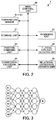
- FIG. 2 is a block diagram showing a control system of this wire electric discharge machine.
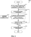
- FIG. 4 is a schematic diagram of a multi-layered neural network.
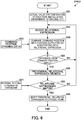
- FIG. 4 is a flowchart showing a sequence of deciding a relational expression between the temperature of machine elements and relative positions of upper/lower guides, in this wire electric discharge machine.
- the wire electric discharge machine 1 is configured from a plurality of machine elements such as a bed 2, column 3, V-axis saddle 5, U-axis saddle 6, Z-axis saddle 7, X-axis saddle 9, Y-axis saddle 10, work pan 11, work table 12, and arm 13.
- the X-axis saddle 9 is equipped to freely move in the X-axis direction (direction perpendicular to plane of page of FIG. 1 ) at an upper side of the bed 2.
- the Y-axis saddle 10 is equipped to freely move in the Y-axis direction (left/right direction in FIG. 1 ) at an upper side of the X-axis saddle 9.
- the work pan 11 is equipped at the upper side of the Y-axis saddle 10.
- the work table 12 on which the work W serving as a workpiece is placed is installed inside of the work pan 11, and is filled with working fluid.
- the column 3 is installed to stand at the upper side of the bed 2.
- the arm 13 is mounted horizontally to the lateral part of the column 3, and the lower guide 15 is mounted to the leading end of the arm 13 so as to be positioned inside of the work pan 11.
- the V-axis saddle 5 is equipped to freely move in the V-axis direction (Y-axis direction) at an upper side of the column 3.
- the U-axis saddle 6 is mounted to freely move in the U-axis direction (X-axis direction) at a lateral part of the V-axis saddle 5.
- the Z-axis saddle 7 is mounted to freely move in the Z-axis direction (up/down direction in FIG. 1 ) at a lateral part of the U-axis saddle 6.
- the upper guide 8 is mounted to the leading end of the Z-axis saddle 7 so as to be positioned above the lower guide 15 inside of the work pan 11.
- the wire electrode 16 is provided in a tensioned state linearly between the upper guide 8 and lower guide 15.
- a temperature sensor 3 is mounted as a temperature detection means to a few of these machine elements, respectively.
- a temperature sensor S1 that detects the temperature of the bed 2 is mounted to the bed 2.
- a temperature sensor S2 that detects the temperature of the Y-axis saddle 10 is mounted to the Y-axis saddle 10.
- a temperature sensor S3 that detects the temperature of the working fluid inside of the work pan 11 is mounted to the work pan 11.
- a temperature sensor S4 that detects the temperature of the column 3 is mounted to the column 3.
- a temperature sensor S5 that detects the temperature of the arm 13 is mounted to the arm 13.
- a temperature sensor S6 that detects the temperature of the V-axis saddle 5 is mounted to the V-axis saddle 5.
- a temperature sensor S7 that detects the temperature of the U-axis saddle 6 is mounted to the U-axis saddle 6.
- the wire electric discharge machine 1 has a main control unit 20 as shown in FIG. 2 .
- a storage unit 21 as a storage means
- a rendering unit 22 as a rendering means
- a position command unit 23 as a position command means
- a relational expression calculation unit 24 as a relational expression calculation means
- a relational expression decision unit 29 as a relational expression decision means
- a correction execution unit 25 as a correction execution means are connected to the main control unit 20.
- the storage unit 21 stores the temperatures detected by the respective temperature sensors S1 to S7 (temperatures of machine elements) as temperature data.
- the rendering unit 22 digitizes the installation environment of the wire electric discharge machine 1 (environment in which the temperature of the wire electric discharge machine 1 rises or lowers from a disturbance, due to a cooler and/or heater being installed in the vicinity of the wire electric discharge machine 1 and operating, for example) by some technique, and renders as environmental data.
- the position command unit 23 commands the relative positions of the upper/lower guides 8, 15.
- the relational expression calculation unit 24 sets the temperature data stored in the storage unit 21 and the environmental data rendered by the rendering unit 22 as input data, and sets the relative positions of the upper/lower guides 8, 15 commanded by the position command unit 23 as training data, and then calculates the relational expression for obtaining the correction amount needed in order to correct the relative positions of the upper/lower guides 8, 15 by way of machine learning.
- X1 to X6 represent the respective input data (temperature data and environmental data in the present embodiment), and W represents output data (relational expression in the present embodiment).
- the relational expression decision unit 29 calculates a correction amount by substituting temperature detected by the temperature sensor S into the relational expression calculated by the relational expression calculation unit 24, obtains an error between the relative positions of the upper/lower guides 8, 15 based on this correction amount and the relative position commanded by the position command unit 23, and determines whether or not this error is small, and in the case of being determined that this error is not small, repeats the calculation of the relational expression by way of machine learning to modify the relational expression, and in the case of being determined that this error is small, decides this relational expression as the formal relational expression.
- the correction execution unit 25 substitutes temperature detected by the temperature sensor S into the relational expression calculated by the relational expression calculation unit 24, calculates an estimated value for the relative positions of the upper/lower guides 8, 15, and based on this estimated value for the relative position, calculates the correction amount for the upper/lower guides 8, 15, and performs correction for the relative positions of the upper/lower guides 8, 15 based on this correction amount.
- the wire electric discharge machine 1 Since the wire electric discharge machine 1 has the above such configuration, the following sequence is followed upon performing electric discharge machining on a work W using this wire electric discharge machine 1. It should be noted that electric discharge machining of this work W is executed based on the commands from the main control unit 20.
- the upper guide 8 is positioned at a predetermined three-dimensional position relative to the lower guide 15, by causing the V-axis saddle 5, U-axis saddle 6 and Z-axis saddle 7 to move appropriately.
- a high-frequency voltage is applied to the wire electrode 16 from a machining power supply (not illustrated).
- the work W is made to relatively move in relation to this wire electrode 16, by causing the X-axis saddle 9 to move in the X-axis direction, and causing the Y-axis saddle 10 to move in the Y-axis direction.
- the storage unit 21 stores the output values of the respective temperature sensors S1 to S7 (temperatures of the bed 2, Y-axis saddle 10, working fluid inside of work pan 11, column 3, arm 13, V-axis saddle 5, and U-axis saddle 6) as temperature data.
- the plurality of measurement times is preferably times at which the output values of the temperature sensors S1 to S7 differ.
- the rendering unit 22 digitizes the installation environment of the wire electric discharge machine 1 for the same plurality of measurement times, and renders as environmental data.
- Step S12 the relational expression calculation unit 24 calculates a relational expression by way of deep learning with the temperature data stored in the storage unit 21 and the environmental data rendered by the rendering unit 22 as input data, and the relative positions of the upper/lower guides 8, 15 commanded by the position command unit 23 as training data.
- the relational expression decision unit 29 calculates a correction amount by substituting output values of the respective temperature sensors S1 to S7 into this relational expression, and obtaining the error between the relative positions of the upper/lower guides 8, 15 based on this correction amount and the relative positions of the upper/lower guides 8, 15 commanded by the position command unit 23.
- Step S15 the relational expression decision unit 29 determines whether or not this error is small. Determination of this magnitude relationship can be determined by providing a predetermined threshold, and determining whether or not smaller than this threshold.
- the position estimation unit 23 calculates the estimated value for the relative positions of the upper/lower guides 8, 15, by substituting the temperatures of each machine element detected by the respective temperature sensors S1 to S7 in this relational expression.
- the correction amount calculation unit 24 calculates the correction amount for the upper/lower guides 8, 15, based on the estimated value for the relative positions of the upper/lower guides 8, 15.
- the correction execution unit 25 performs correction of the relative positions of the upper/lower guides 8, 15, based on this correction amount of the upper/lower guides 8, 15.
- FIG. 5 is a block diagram showing a control system of a wire electric discharge machine according to a second embodiment of the present invention.
- FIG. 6 is a flowchart showing a sequence of deciding a relational expression between the temperatures of the machine element and relative positions of the upper/lower guides, in this wire electric discharge machine.
- a data sharing unit 26 as a data sharing means, a determination unit 27 as a determination means, and a relational expression modification unit 28 as a relational expression modification means are added in the control system thereof, as shown in FIG. 5 . Since other configurations are basically the same as the aforementioned first embodiment, the same reference symbols are assigned for identical members, and explanations thereof are omitted.
- the data sharing unit 26 shares a plurality of relational expressions for cases in which the installation environment of the wire electric discharge machine 1 differs.
- the determination unit 27 determines whether or not the plurality of relational expression shared by the data sharing unit 26 are in agreement with each other.
- the relational expression modification unit 28 in the case of being determined by way of the determination unit 27 that the plurality of relational expression are not in agreement with each other, modifies the relational expression by repeating the calculation of the relational expression by way of machine learning, and in the case of being determined that the plurality of relational expression are in agreement with each other, adopts this relational expression as the official form.
- a relational expression decision program PRG2 shown in FIG. 6 is followed upon obtaining the relational expression between the temperatures of each machine element and the relative positions of the upper/lower guides 8, 15.
- Step S21 the storage unit 21 executes the same processing as Step S11 in the aforementioned first embodiment.
- Step S22 the relational expression calculation unit 24 executes the same processing as Step S12 in the aforementioned first embodiment.
- Steps S23 and S24 the relational expression decision unit 29 executes the same processing as Steps S13 and S14 in the aforementioned first embodiment.
- Step S25 the relational expression decision unit 29 executes the same processing as Step S15 in the aforementioned first embodiment.
- Step S26 the relational expression decision unit 29 executes the same processing as Step S16 in the aforementioned first embodiment.
- Step S27 the data sharing unit 26 shares a plurality of relational expressions for cases of the installation environments of the wire electric discharge machine 1 differing.
- Step S28 the determination unit 27 determines whether or not the plurality of relational expressions shared by the data sharing unit 26 are in agreement with each other.
- the processing returns to Step S22, and repeats the calculation of the relational expression by way of machine learning.
- the processing advances to Step S29, and the relational expression modification unit 28 adopts this relational expression as the official form.
- the present embodiment exerts the same functional effects as the aforementioned first embodiment.
- calculation of the relational expression is repeated by machine learning until a plurality of relational expressions are in agreement with each other. For this reason, it is possible to derive a relational expression commonly usable in a plurality of installation environments, and it becomes possible to raise the versatility of the wire electric discharge machine 1.
- the wire electric discharge machine 1 in which temperature sensors S are mounted to seven machine elements has been explained.
- the mounting locations of the temperature sensors S are not limited to the aforementioned machine elements, and for example, temperature sensors S may be mounted to the X-axis saddle 9 and/or Z-axis saddle 7. Alternatively, it will not cause a problem even if mounting a plurality of temperature sensors S to any one machine element.
- the atmospheric temperature around the wire electric discharge machine 1 may be measured by a temperature sensor (not illustrated).
- a wire electric discharge machine 1 of mobile-type upper guide 8 and fixed-type lower guide 15 has been explained in the aforementioned first embodiment and second embodiment.
Landscapes
- Engineering & Computer Science (AREA)
- Chemical & Material Sciences (AREA)
- Chemical Kinetics & Catalysis (AREA)
- Electrochemistry (AREA)
- Mechanical Engineering (AREA)
- Automation & Control Theory (AREA)
- Human Computer Interaction (AREA)
- Manufacturing & Machinery (AREA)
- Physics & Mathematics (AREA)
- General Physics & Mathematics (AREA)
- Electrical Discharge Machining, Electrochemical Machining, And Combined Machining (AREA)
- Automatic Control Of Machine Tools (AREA)
Abstract
Description
- The present invention relates to a wire electric discharge machine that performs electric discharge machining on a workpiece, by causing the workpiece and a wire electrode mounted between an upper guide and lower guide to relatively move, in a state in which the upper guide and lower guide are arranged at predetermined relative positions.
- Such a wire electric discharge machine is configured by a plurality of machine elements being combined, and the thermal expansion coefficients of these machine elements differ from each other. Therefore, due to factors such as a change in the temperature of the environment, there is concern over a plurality of machine elements thermally deforming and the relative positions of the upper guide and lower guide displacing in three-dimensional directions (X-axis direction, Y-axis direction, Z-axis direction). If positional shift in the horizontal direction (X-axis direction, Y-axis direction) occurs in particular, it will be directly linked to a decline in machining precision. Therefore, in order to prevent a change in the temperature of the environment, countermeasures for temperature management by installing the wire electric discharge machine in a temperature-controlled room or the like have also been considered; however, the investment of a great sum of capitol is required in order to install a temperature-controlled room of adequate performance.
- For this reason, as a method of maintaining machining precision inexpensively, a technique of performing correction by assuming a thermal displacement amount of the upper and lower guides based on temperature information detected by a temperature sensors installed to various parts of the machine, so-called thermal displacement correction, has been proposed.
- Upon performing this thermal displacement correction, if considering that there are cases where the temperature of the surroundings change from the installation environment of the wire electric discharge machine changing, it is desirable to be able to suitably perform thermal displacement correction continuously, even if the installation environment of the wire electric discharge machine changed, for example. In order to respond to such demands, technology has been proposed that obtains an appropriate thermal displacement correction amount irrespective of the installation environment of the wire electric discharge machine (for example, refer to
Patent Documents 1 and 2). - Patent Document 1: Japanese Patent No.
5870143 - Patent Document 2: Japanese Unexamined Patent Application, Publication No.
H7-75937 - However, with the technology described in
Patent Document 1, machine learning is not being used upon decision of the correction amount computing equation, and there is a possibility of not being able to adjust to the optimum correction amount simply by using a factor, depending on the way of selecting the correction amount computing equation to be created in advance. - In addition, with the technology described in
Patent Document 2, the correction amount is calculated using the same data in the case of the installation environment of the wire electric discharge machine not differing extremely, and the difference in correction amount due to the installation environment of the wire electric discharge machine is not given much consideration. Furthermore, although a method of recalculating the correction equation by repeating the measurement of data after installing the wire electric discharge machine is disclosed inPatent Document 2, this involves a disadvantage in that work hours are required at the factory. - The present invention takes account of such a situation, and has an object of providing a wire electric discharge machine capable of suitably performing thermal displacement correction on upper/lower guides, even if the installation environment changes.
- A wire electric discharge machine (e.g., the wire
electric discharge machine 1 described later) according to a first aspect of the present invention is a wire electric discharge machine configured from a plurality of machine elements (e.g., thebed 2,column 3, X-axis saddle 9, Y-axis saddle 10, etc. described later), and performing electric discharge machining on a workpiece (e.g., the work W described later) in a state in which an upper guide (e.g., theupper guide 8 described later) and a lower guide (e.g., thelower guide 15 described later) are disposed at predetermined relative positions, by causing the workpiece and a wire electrode (e.g., thewire electrode 16 described later) installed between the upper guide and the lower guide to relatively move, the wire electric discharge machine including: a temperature detection means (e.g., the temperature sensors S1 to S7 described later) for detecting temperature of at least one machine element among the plurality of machine elements; a storage means (e.g., thestorage unit 21 described later) for storing temperatures detected by the temperature detection means as temperature data; a rendering means (e.g., therendering unit 22 described later) for digitizing an installation environment, and rendering as environmental data; a position command means (e.g., theposition command unit 23 described later) for commanding a relative position of the upper guide and the lower guide; a relational expression calculation means (e.g., the relationalexpression calculation unit 24 described later) for calculating a relational expression by way of the machine learning for obtaining a correction amount required in order to correct the relative position of the upper guide and the lower guide, by setting the temperature data stored in the storage means and the environmental data rendered by the rendering means as input data, and setting a relative position commanded by the position command means as training data; a relational expression decision means (e.g., the relationalexpression decision unit 29 described later) for calculating a correction amount by substituting the temperature detected by the temperature detection means into the relational expression calculated by the relational expression calculation means, obtaining error between the relative position of the upper guide and the lower guide based on said correction amount and the relative position commanded by the position command means, and determining whether said error is small, and in the case of being determined that said error is not small, modifying the relational expression by repeating calculation of the relational expression by way of machine learning, and in the case of being determined that said error is small, deciding said relational expression as a formal relational expression; and a correction execution means (e.g., thecorrection execution unit 25 described later) for calculating an estimated value for the relative position by substituting the temperature detected by the temperature detection means into the relational expression decided by the relational expression decision means, then calculating a correction amount for the upper guide and the lower guide based on said estimated value for the relative position, and performing correction on the relative position of the upper guide and the lower guide based on said correction amount. - According to a second aspect of the present invention, the wire electric discharge machine as described in the first aspect may further include: a data sharing means (e.g., the
data sharing unit 26 described later) for sharing a plurality of the relational expressions for cases of installation environments differing; a determination means (e.g., thedetermination unit 27 described later) for determining whether the plurality of the relational expressions shared by the data sharing means are in agreement with each other; and a relational expression modification means (e.g., the relationalexpression modification unit 28 described later) for, in a case of the determination means determining that the plurality of the relational expressions shared by the data sharing means are not in agreement with each other, modifying the relational expression by repeating calculation of the relational expression by way of the machine learning, and in a case of the determination means determining that the plurality of the relational expressions shared by the data sharing means are in agreement with each other, formally adopting said relational expression. - According to a third aspect of the present invention, in the wire electric discharge machine as described in the first or second aspect, the relational expression calculation means may perform the machine learning by following a learning model constructed by way of a multi-layered neural network.
- According to the present invention, it is possible to calculate the correction amount of upper/lower guides in a form in which the difference in installation environments thereof are reflected for a wire electric discharge machine. For this reason, even if the installation environment of the wire electric discharge machine changes, it is possible to suitably perform thermal displacement correction of the upper/lower guides.
-
-
FIG. 1 is a front view showing an outline configuration of a wire electric discharge machine according to a first embodiment of the present invention; -
FIG. 2 is a block diagram showing a control system of the wire electric discharge machine according to the first embodiment of the present invention; -
FIG. 3 is a schematic diagram of a multi-layered neural network; -
FIG. 4 is a flowchart showing a sequence of deciding a relational expression between the temperature of machine elements and relative positions of upper/lower guides, in the wire electric discharge machine according to the first embodiment of the present invention; -
FIG. 5 is a block diagram showing a control system of a wire electric discharge machine according to a second embodiment of the present invention; and -
FIG. 6 is a flowchart showing a sequence of deciding a relational expression between the temperature of machine elements and relative positions of upper/lower guides, in the wire electric discharge machine according to the third embodiment of the present invention. - Hereinafter, a first embodiment of the present invention will be explained based on the drawings.
-
FIG. 1 is a front view showing an outline configuration of a wire electric discharge machine according to the first embodiment of the present invention.FIG. 2 is a block diagram showing a control system of this wire electric discharge machine.FIG. 4 is a schematic diagram of a multi-layered neural network.FIG. 4 is a flowchart showing a sequence of deciding a relational expression between the temperature of machine elements and relative positions of upper/lower guides, in this wire electric discharge machine. - The wire
electric discharge machine 1 according to the first embodiment is configured from a plurality of machine elements such as abed 2,column 3, V-axis saddle 5,U-axis saddle 6, Z-axis saddle 7, X-axis saddle 9, Y-axis saddle 10,work pan 11, work table 12, andarm 13. - Herein, the X-axis saddle 9 is equipped to freely move in the X-axis direction (direction perpendicular to plane of page of
FIG. 1 ) at an upper side of thebed 2. The Y-axis saddle 10 is equipped to freely move in the Y-axis direction (left/right direction inFIG. 1 ) at an upper side of the X-axis saddle 9. Thework pan 11 is equipped at the upper side of the Y-axis saddle 10. The work table 12 on which the work W serving as a workpiece is placed is installed inside of thework pan 11, and is filled with working fluid. - In addition, the
column 3 is installed to stand at the upper side of thebed 2. Thearm 13 is mounted horizontally to the lateral part of thecolumn 3, and thelower guide 15 is mounted to the leading end of thearm 13 so as to be positioned inside of thework pan 11. The V-axis saddle 5 is equipped to freely move in the V-axis direction (Y-axis direction) at an upper side of thecolumn 3. TheU-axis saddle 6 is mounted to freely move in the U-axis direction (X-axis direction) at a lateral part of the V-axis saddle 5. The Z-axis saddle 7 is mounted to freely move in the Z-axis direction (up/down direction inFIG. 1 ) at a lateral part of theU-axis saddle 6. Theupper guide 8 is mounted to the leading end of the Z-axis saddle 7 so as to be positioned above thelower guide 15 inside of thework pan 11. Thewire electrode 16 is provided in a tensioned state linearly between theupper guide 8 andlower guide 15. - Furthermore, among these machine elements, a
temperature sensor 3 is mounted as a temperature detection means to a few of these machine elements, respectively. In other words, a temperature sensor S1 that detects the temperature of thebed 2 is mounted to thebed 2. A temperature sensor S2 that detects the temperature of the Y-axis saddle 10 is mounted to the Y-axis saddle 10. A temperature sensor S3 that detects the temperature of the working fluid inside of thework pan 11 is mounted to thework pan 11. A temperature sensor S4 that detects the temperature of thecolumn 3 is mounted to thecolumn 3. A temperature sensor S5 that detects the temperature of thearm 13 is mounted to thearm 13. A temperature sensor S6 that detects the temperature of the V-axis saddle 5 is mounted to the V-axis saddle 5. A temperature sensor S7 that detects the temperature of theU-axis saddle 6 is mounted to theU-axis saddle 6. - Furthermore, the wire
electric discharge machine 1 has amain control unit 20 as shown inFIG. 2 . In addition to the aforementioned seven temperature sensors S (S1∼S7), astorage unit 21 as a storage means, arendering unit 22 as a rendering means, aposition command unit 23 as a position command means, a relationalexpression calculation unit 24 as a relational expression calculation means, a relationalexpression decision unit 29 as a relational expression decision means, and acorrection execution unit 25 as a correction execution means are connected to themain control unit 20. - The
storage unit 21 stores the temperatures detected by the respective temperature sensors S1 to S7 (temperatures of machine elements) as temperature data. - The
rendering unit 22 digitizes the installation environment of the wire electric discharge machine 1 (environment in which the temperature of the wireelectric discharge machine 1 rises or lowers from a disturbance, due to a cooler and/or heater being installed in the vicinity of the wireelectric discharge machine 1 and operating, for example) by some technique, and renders as environmental data. - The
position command unit 23 commands the relative positions of the upper/lower guides - The relational
expression calculation unit 24 sets the temperature data stored in thestorage unit 21 and the environmental data rendered by therendering unit 22 as input data, and sets the relative positions of the upper/lower guides position command unit 23 as training data, and then calculates the relational expression for obtaining the correction amount needed in order to correct the relative positions of the upper/lower guides - Upon this machine learning, deep learning is performed following a learning model (algorithm) constructed by a multi-layered neural network as shown in
FIG. 3 . InFIG. 3 , X1 to X6 represent the respective input data (temperature data and environmental data in the present embodiment), and W represents output data (relational expression in the present embodiment). - The relational
expression decision unit 29 calculates a correction amount by substituting temperature detected by the temperature sensor S into the relational expression calculated by the relationalexpression calculation unit 24, obtains an error between the relative positions of the upper/lower guides position command unit 23, and determines whether or not this error is small, and in the case of being determined that this error is not small, repeats the calculation of the relational expression by way of machine learning to modify the relational expression, and in the case of being determined that this error is small, decides this relational expression as the formal relational expression. - The
correction execution unit 25 substitutes temperature detected by the temperature sensor S into the relational expression calculated by the relationalexpression calculation unit 24, calculates an estimated value for the relative positions of the upper/lower guides lower guides lower guides - Since the wire
electric discharge machine 1 has the above such configuration, the following sequence is followed upon performing electric discharge machining on a work W using this wireelectric discharge machine 1. It should be noted that electric discharge machining of this work W is executed based on the commands from themain control unit 20. - First, in response to the machined form of the work W, the
upper guide 8 is positioned at a predetermined three-dimensional position relative to thelower guide 15, by causing the V-axis saddle 5,U-axis saddle 6 and Z-axis saddle 7 to move appropriately. Next, a high-frequency voltage is applied to thewire electrode 16 from a machining power supply (not illustrated). In this state, the work W is made to relatively move in relation to thiswire electrode 16, by causing the X-axis saddle 9 to move in the X-axis direction, and causing the Y-axis saddle 10 to move in the Y-axis direction. - In electric discharge machining of the work W done in this way, there is concern over the relative positions of the upper/
lower guides lower guides lower guides FIG. 4 , as mentioned below. It should be noted that this thermal displacement correction is executed based on the commands from themain control unit 20. In addition, as stages for this thermal displacement correction, prior to factory delivery or during initial setting of the wireelectric discharge machine 1, during maintenance, or the like are desired. - First, in Step S11, the
storage unit 21 stores the output values of the respective temperature sensors S1 to S7 (temperatures of thebed 2, Y-axis saddle 10, working fluid inside ofwork pan 11,column 3,arm 13, V-axis saddle 5, and U-axis saddle 6) as temperature data. At this time, the plurality of measurement times is preferably times at which the output values of the temperature sensors S1 to S7 differ. In addition, therendering unit 22 digitizes the installation environment of the wireelectric discharge machine 1 for the same plurality of measurement times, and renders as environmental data. - Next, in Step S12, the relational
expression calculation unit 24 calculates a relational expression by way of deep learning with the temperature data stored in thestorage unit 21 and the environmental data rendered by therendering unit 22 as input data, and the relative positions of the upper/lower guides position command unit 23 as training data. - Next, in Steps S13 and S14, the relational
expression decision unit 29 calculates a correction amount by substituting output values of the respective temperature sensors S1 to S7 into this relational expression, and obtaining the error between the relative positions of the upper/lower guides lower guides position command unit 23. - Subsequently, in Step S15, the relational
expression decision unit 29 determines whether or not this error is small. Determination of this magnitude relationship can be determined by providing a predetermined threshold, and determining whether or not smaller than this threshold. - As a result thereof, in the case of being determined that this error is not small, since it is considered that the probability of this relational expression being statistically suitable is low, the processing returns to Step S12, and repeats the calculation of the relational expression by way of machine learning. On the other hand, in the case of being determined that this error is small, since it is considered that the probability of this relational expression being statistically suitable is high, the processing advances to Step S16, and the relational
expression decision unit 29 decides this relational expression as the formal relational expression. - Herein, the operations for obtaining the relational expression between the temperatures of each machine element and the relative positions of the upper/
lower guides - Upon the relational expression between the temperatures of each machine element and the relative positions of the upper/
lower guides lower guides - In other words, first, the
position estimation unit 23 calculates the estimated value for the relative positions of the upper/lower guides amount calculation unit 24 calculates the correction amount for the upper/lower guides lower guides correction execution unit 25 performs correction of the relative positions of the upper/lower guides lower guides - In the above way, according to the present embodiment, it is possible to calculate the correction amount for the upper/
lower guides electric discharge machine 1. For this reason, even if the installation environment of the wireelectric discharge machine 1 changes, it is possible to suitably perform thermal displacement correction of the upper/lower guides - In addition, upon calculating the relational expression for obtaining the correction amount required in order to correct the relative positions of the upper/
lower guides -
FIG. 5 is a block diagram showing a control system of a wire electric discharge machine according to a second embodiment of the present invention.FIG. 6 is a flowchart showing a sequence of deciding a relational expression between the temperatures of the machine element and relative positions of the upper/lower guides, in this wire electric discharge machine. - For the wire
electric discharge machine 1 according to the second embodiment, adata sharing unit 26 as a data sharing means, adetermination unit 27 as a determination means, and a relationalexpression modification unit 28 as a relational expression modification means are added in the control system thereof, as shown inFIG. 5 . Since other configurations are basically the same as the aforementioned first embodiment, the same reference symbols are assigned for identical members, and explanations thereof are omitted. - The
data sharing unit 26 shares a plurality of relational expressions for cases in which the installation environment of the wireelectric discharge machine 1 differs. - The
determination unit 27 determines whether or not the plurality of relational expression shared by thedata sharing unit 26 are in agreement with each other. - The relational
expression modification unit 28, in the case of being determined by way of thedetermination unit 27 that the plurality of relational expression are not in agreement with each other, modifies the relational expression by repeating the calculation of the relational expression by way of machine learning, and in the case of being determined that the plurality of relational expression are in agreement with each other, adopts this relational expression as the official form. - Next, in the wire
electric discharge machine 1 according to the present embodiment, a relational expression decision program PRG2 shown inFIG. 6 is followed upon obtaining the relational expression between the temperatures of each machine element and the relative positions of the upper/lower guides - First, in Step S21, the
storage unit 21 executes the same processing as Step S11 in the aforementioned first embodiment. - Next, in Step S22, the relational
expression calculation unit 24 executes the same processing as Step S12 in the aforementioned first embodiment. - Subsequently, in Steps S23 and S24, the relational
expression decision unit 29 executes the same processing as Steps S13 and S14 in the aforementioned first embodiment. - Next, in Step S25, the relational
expression decision unit 29 executes the same processing as Step S15 in the aforementioned first embodiment. - Then, in Step S26, the relational
expression decision unit 29 executes the same processing as Step S16 in the aforementioned first embodiment. - Furthermore, in Step S27, the
data sharing unit 26 shares a plurality of relational expressions for cases of the installation environments of the wireelectric discharge machine 1 differing. - Next, in Step S28, the
determination unit 27 determines whether or not the plurality of relational expressions shared by thedata sharing unit 26 are in agreement with each other. - As a result thereof, in the case of being determined that the plurality of relational expressions are not in agreement with each other, since it is not considered to be able to commonly use this relational expression for the plurality of installation environments, the processing returns to Step S22, and repeats the calculation of the relational expression by way of machine learning. On the other hand, in the case of being determined that the plurality of relational expressions are in agreement with each other, since it is considered to be able to commonly use this relational expression for the plurality of installation environments, the processing advances to Step S29, and the relational
expression modification unit 28 adopts this relational expression as the official form. - Herein, the operations for obtaining the relational expression between the temperatures of each machine element and the relative positions of the upper/
lower guides - Upon the relational expression between the temperature of each machine element and the relative positions of the upper/
lower guides lower guides - In the above way, the present embodiment exerts the same functional effects as the aforementioned first embodiment. In addition thereto, according to the present embodiment, calculation of the relational expression is repeated by machine learning until a plurality of relational expressions are in agreement with each other. For this reason, it is possible to derive a relational expression commonly usable in a plurality of installation environments, and it becomes possible to raise the versatility of the wire
electric discharge machine 1. - Although embodiments of the present invention have been explained above, the present invention is not to be limited to the aforementioned embodiments. In addition, the effects described in the present embodiments are merely exemplifying the most preferred effects produced from the present invention, and the effects according to the present invention are not to be limited to those described in the present embodiments.
- In addition, although cases of performing deep learning upon calculating the relational expression for obtaining the correction amount required in order to correct the relative positions of the upper/
lower guides - In addition, in the aforementioned first embodiment and second embodiment, the wire
electric discharge machine 1 in which temperature sensors S are mounted to seven machine elements (bed 2, Y-axis saddle 10, working fluid inside ofwork pan 11,column 3,arm 13, V-axis saddle 5, U-axis saddle 6) has been explained. However, the mounting locations of the temperature sensors S are not limited to the aforementioned machine elements, and for example, temperature sensors S may be mounted to the X-axis saddle 9 and/or Z-axis saddle 7. Alternatively, it will not cause a problem even if mounting a plurality of temperature sensors S to any one machine element. Furthermore, the atmospheric temperature around the wireelectric discharge machine 1 may be measured by a temperature sensor (not illustrated). - Furthermore, a wire
electric discharge machine 1 of mobile-typeupper guide 8 and fixed-typelower guide 15 has been explained in the aforementioned first embodiment and second embodiment. However, it is conversely possible to similarly apply the present invention to a wire electric discharge machine of fixed-typeupper guide 8 and mobile-typelower guide 15. In addition, it is also possible to similarly apply the present invention to a wire electric discharge machine with both mobile-typeupper guide 8 andlower guide 15. -
- 1 wire electric discharge machine
- 2 bed (machine element)
- 3 column (machine element)
- 5 V-axis saddle (machine element)
- 6 U-axis saddle (machine element)
- 7 Z-axis saddle (machine element)
- 8 upper guide
- 9 X-axis saddle (machine element)
- 10 Y-axis saddle (machine element)
- 11 work pan (machine element)
- 12 work table (machine element)
- 13 arm (machine element)
- 15 lower guide
- 16 wire electrode
- 21 storage unit (storage means)
- 22 rendering unit (rendering means)
- 23 position command unit (position command means)
- 24 relational expression calculation unit (relational expression calculation means)
- 25 correction execution unit (correction execution means)
- 26 data sharing unit (data sharing means)
- 27 determination unit (determination means)
- 28 relational expression modification unit (relational expression modification means)
- 29 relational expression decision unit (relational expression decision means)
- S, S1∼S7 temperature sensor (temperature detection means)
- W work (workpiece)
Claims (3)
- A wire electric discharge machine (1) configured from a plurality of machine elements (2, 3, 9, 10), and performing electric discharge machining on a workpiece (W) in a state in which an upper guide (8) and a lower guide (15) are disposed at predetermined relative positions, by causing the workpiece (W) and a wire electrode (16) installed between the upper guide and the lower guide to relatively move, the wire electric discharge machine (1) comprising:a temperature detection means (S1 to S7) for detecting temperature of at least one machine element (2, 3, 9, 10) among the plurality of machine elements (2, 3, 9, 10);a storage means (21) for storing temperatures detected by the temperature detection means (S1 to S7) as temperature data;a rendering means (22) for digitizing an installation environment, and rendering as environmental data;a position command means (23) for commanding a relative position of the upper guide (8) and the lower guide (15);a relational expression calculation means (24) for calculating a relational expression by way of the machine learning for obtaining a correction amount required in order to correct the relative position of the upper guide (8) and the lower guide (15), by setting the temperature data stored in the storage means (21) and the environmental data rendered by the rendering means (22) as input data, and setting a relative position commanded by the position command means (23) as training data;a relational expression decision means (29) for calculating a correction amount by substituting the temperature detected by the temperature detection means (S1 to S7) into the relational expression calculated by the relational expression calculation means (24), obtaining error between the relative position of the upper guide (8) and the lower guide (15) based on said correction amount and the relative position commanded by the position command means (23), and determining whether said error is small, and in the case of being determined that said error is not small, modifying the relational expression by repeating calculation of the relational expression by way of machine learning, and in the case of being determined that said error is small, deciding said relational expression as a formal relational expression; anda correction execution means (25) for calculating an estimated value for the relative position by substituting the temperature detected by the temperature detection means (S1 to S7) into the relational expression decided by the relational expression decision means (29), then calculating a correction amount for the upper guide (8) and the lower guide (15) based on said estimated value for the relative position, and performing correction on the relative position of the upper guide (8) and the lower guide (15) based on said correction amount.
- The wire electric discharge machine (1) according to claim 1, further comprising:a data sharing means (26) for sharing a plurality of the relational expressions for cases of installation environments differing;a determination means (27) for determining whether the plurality of the relational expressions shared by the data sharing means (26) are in agreement with each other; anda relational expression modification means (28) for, in a case of the determination means (27) determining that the plurality of the relational expressions shared by the data sharing means (26) are not in agreement with each other, modifying the relational expression by repeating calculation of the relational expression by way of the machine learning, and in a case of the determination means determining that the plurality of the relational expressions shared by the data sharing means (26) are in agreement with each other, formally adopting said relational expression.
- The wire electric discharge machine (1) according to claim 1 or 2, wherein the relational expression calculation means (24) performs the machine learning by following a learning model constructed by way of a multi-layered neural network.
Applications Claiming Priority (1)
| Application Number | Priority Date | Filing Date | Title |
|---|---|---|---|
| JP2016214384A JP6444959B2 (en) | 2016-11-01 | 2016-11-01 | Wire electric discharge machine |
Publications (2)
| Publication Number | Publication Date |
|---|---|
| EP3316056A1 true EP3316056A1 (en) | 2018-05-02 |
| EP3316056B1 EP3316056B1 (en) | 2021-08-11 |
Family
ID=60191244
Family Applications (1)
| Application Number | Title | Priority Date | Filing Date |
|---|---|---|---|
| EP17199132.6A Active EP3316056B1 (en) | 2016-11-01 | 2017-10-30 | Wire electric discharge machine |
Country Status (6)
| Country | Link |
|---|---|
| US (1) | US10300543B2 (en) |
| EP (1) | EP3316056B1 (en) |
| JP (1) | JP6444959B2 (en) |
| KR (1) | KR101997753B1 (en) |
| CN (1) | CN107999913B (en) |
| TW (1) | TWI665044B (en) |
Cited By (2)
| Publication number | Priority date | Publication date | Assignee | Title |
|---|---|---|---|---|
| EP3948455A1 (en) * | 2019-04-05 | 2022-02-09 | Deckel Maho Seebach GmbH | Method and device for compensating for a thermally induced change in position on a numerically controlled machine tool |
| CN120076893A (en) * | 2023-05-15 | 2025-05-30 | 三菱电机株式会社 | Wire electric discharge machine |
Families Citing this family (10)
| Publication number | Priority date | Publication date | Assignee | Title |
|---|---|---|---|---|
| JP6444959B2 (en) * | 2016-11-01 | 2018-12-26 | ファナック株式会社 | Wire electric discharge machine |
| JP6673950B2 (en) * | 2018-01-31 | 2020-04-01 | ファナック株式会社 | Reference temperature setting device, reference temperature setting method and reference temperature setting program |
| JP6558818B1 (en) * | 2018-10-19 | 2019-08-14 | 株式会社ソディック | EDM machine |
| JP6863951B2 (en) | 2018-11-08 | 2021-04-21 | ファナック株式会社 | Wire disconnection predictor |
| KR102035064B1 (en) | 2019-02-25 | 2019-10-23 | 주식회사 세로 | Cleaning apparatus for wire electric discharge machin |
| JP7000376B2 (en) * | 2019-04-23 | 2022-01-19 | ファナック株式会社 | Machine learning equipment, prediction equipment, and control equipment |
| JP6661065B1 (en) * | 2019-07-05 | 2020-03-11 | 三菱電機株式会社 | Machine learning device, wire electric discharge machining system, and machine learning method |
| JP7481112B2 (en) * | 2019-12-26 | 2024-05-10 | ファナック株式会社 | Thermal Displacement Compensation Device |
| JP3234112U (en) | 2020-12-04 | 2021-09-24 | ファナック株式会社 | Machine Tools |
| DE112022005089B4 (en) * | 2022-06-27 | 2026-01-22 | Mitsubishi Electric Corporation | Control unit for a wire EDM machine and control method for a wire EDM machine |
Citations (3)
| Publication number | Priority date | Publication date | Assignee | Title |
|---|---|---|---|---|
| JPH0775937A (en) | 1993-09-07 | 1995-03-20 | Sodick Co Ltd | Machine tool and control method thereof |
| US20130325164A1 (en) * | 2011-02-24 | 2013-12-05 | Mitsubishi Electric Corporation | Electric discharge machine and electric discharge machining system |
| US20150283636A1 (en) * | 2014-04-03 | 2015-10-08 | Fanuc Corporation | Wire electrical discharge machine having upper/lower guide thermal displacement correction function |
Family Cites Families (23)
| Publication number | Priority date | Publication date | Assignee | Title |
|---|---|---|---|---|
| JPS5652132A (en) * | 1979-10-03 | 1981-05-11 | Inoue Japax Res Inc | Control system for feeding |
| JPS5870143A (en) | 1981-10-22 | 1983-04-26 | Eikomu:Kk | Testing equipment |
| WO1988003074A1 (en) * | 1986-10-24 | 1988-05-05 | Mitsubishi Denki Kabushiki Kaisha | Electric discharge apparatus |
| JPH068107A (en) * | 1992-06-29 | 1994-01-18 | Hitachi Seiko Ltd | Thermal displacement compensation method for machine tool |
| JPH10315057A (en) * | 1997-05-21 | 1998-12-02 | Mitsubishi Electric Corp | Wire electric discharge machine |
| JPH11114776A (en) * | 1997-10-13 | 1999-04-27 | Niigata Eng Co Ltd | Thermal displacement correcting device for machine tool |
| DE69934251T2 (en) * | 1999-10-20 | 2007-07-05 | Makino Milling Machine Co. Ltd. | NC TOOL MACHINE AND METHOD FOR CONTROLLING THE NC TOOL MACHINE |
| US20030205984A1 (en) * | 2001-06-20 | 2003-11-06 | Jun Yoshida | Method of controlling numerically controlled machine tool and numerically controlled machine tool |
| JP3756793B2 (en) * | 2001-07-27 | 2006-03-15 | オークマ株式会社 | Machine tool thermal displacement compensation device |
| TWI228438B (en) | 2003-12-31 | 2005-03-01 | Ind Tech Res Inst | Automatic electric-discharge-machining program generation device with stage by stage parameter adjustment |
| JP2005335027A (en) * | 2004-05-28 | 2005-12-08 | Fanuc Ltd | Electric discharge machine and working liquid cooling device |
| JP4008435B2 (en) * | 2004-06-29 | 2007-11-14 | ファナック株式会社 | Wire cutting machine for wire electric discharge machine |
| JP2007203408A (en) * | 2006-02-01 | 2007-08-16 | Fanuc Ltd | Apparatus for treating working fluid of wire electric discharge machine |
| JP4153534B2 (en) * | 2006-05-30 | 2008-09-24 | ファナック株式会社 | Wire electric discharge machine |
| EP2422910B1 (en) * | 2010-08-25 | 2015-09-16 | Fanuc Corporation | Wire-cut electric discharge machine having function for automatic switching between fixed temperature control and differential temperature control |
| JP5674033B2 (en) * | 2011-03-28 | 2015-02-18 | 西部電機株式会社 | Wire electric discharge machine, head control method, and program thereof |
| JP5232314B1 (en) * | 2012-02-13 | 2013-07-10 | ファナック株式会社 | Wire electrical discharge machine with temperature control function of machining fluid |
| JP5657715B2 (en) * | 2013-01-11 | 2015-01-21 | ファナック株式会社 | Wire electrical discharge machine with wire electrode position correction function |
| JP6133917B2 (en) * | 2015-03-06 | 2017-05-24 | ファナック株式会社 | Wire electric discharge machine having a function of correcting the detected tension value |
| JP6407922B2 (en) * | 2016-07-21 | 2018-10-17 | ファナック株式会社 | Wire electric discharge machine |
| JP6444959B2 (en) * | 2016-11-01 | 2018-12-26 | ファナック株式会社 | Wire electric discharge machine |
| JP6382911B2 (en) * | 2016-11-01 | 2018-08-29 | ファナック株式会社 | Wire electric discharge machine |
| JP2018118348A (en) * | 2017-01-26 | 2018-08-02 | ファナック株式会社 | Control device for wire electric discharge machine |
-
2016
- 2016-11-01 JP JP2016214384A patent/JP6444959B2/en active Active
-
2017
- 2017-10-27 US US15/795,748 patent/US10300543B2/en active Active
- 2017-10-30 EP EP17199132.6A patent/EP3316056B1/en active Active
- 2017-10-31 CN CN201711045368.XA patent/CN107999913B/en active Active
- 2017-10-31 TW TW106137611A patent/TWI665044B/en active
- 2017-10-31 KR KR1020170143572A patent/KR101997753B1/en active Active
Patent Citations (5)
| Publication number | Priority date | Publication date | Assignee | Title |
|---|---|---|---|---|
| JPH0775937A (en) | 1993-09-07 | 1995-03-20 | Sodick Co Ltd | Machine tool and control method thereof |
| US5523953A (en) * | 1993-09-07 | 1996-06-04 | Sodick Co., Ltd. | Method and apparatus for correcting positioning errors on a machine tool |
| US20130325164A1 (en) * | 2011-02-24 | 2013-12-05 | Mitsubishi Electric Corporation | Electric discharge machine and electric discharge machining system |
| US20150283636A1 (en) * | 2014-04-03 | 2015-10-08 | Fanuc Corporation | Wire electrical discharge machine having upper/lower guide thermal displacement correction function |
| JP5870143B2 (en) | 2014-04-03 | 2016-02-24 | ファナック株式会社 | Wire electrical discharge machine with thermal displacement compensation function for upper and lower guides |
Cited By (3)
| Publication number | Priority date | Publication date | Assignee | Title |
|---|---|---|---|---|
| EP3948455A1 (en) * | 2019-04-05 | 2022-02-09 | Deckel Maho Seebach GmbH | Method and device for compensating for a thermally induced change in position on a numerically controlled machine tool |
| US12197183B2 (en) | 2019-04-05 | 2025-01-14 | Deckel Maho Seebach Gmbh | Method and device for compensating for a thermally induced change in position on a numerically controlled machine tool |
| CN120076893A (en) * | 2023-05-15 | 2025-05-30 | 三菱电机株式会社 | Wire electric discharge machine |
Also Published As
| Publication number | Publication date |
|---|---|
| CN107999913B (en) | 2019-09-24 |
| US20180117693A1 (en) | 2018-05-03 |
| KR101997753B1 (en) | 2019-07-08 |
| TW201817524A (en) | 2018-05-16 |
| JP6444959B2 (en) | 2018-12-26 |
| JP2018069409A (en) | 2018-05-10 |
| EP3316056B1 (en) | 2021-08-11 |
| TWI665044B (en) | 2019-07-11 |
| US10300543B2 (en) | 2019-05-28 |
| CN107999913A (en) | 2018-05-08 |
| KR20180048392A (en) | 2018-05-10 |
Similar Documents
| Publication | Publication Date | Title |
|---|---|---|
| EP3316056B1 (en) | Wire electric discharge machine | |
| EP3316057B1 (en) | Wire electric discharge machine | |
| JP5562430B2 (en) | Tool path generation method and generation apparatus | |
| JP4291385B2 (en) | Robot controller that stops the robot based on the speed of the robot hand | |
| JP7481112B2 (en) | Thermal Displacement Compensation Device | |
| US9849529B2 (en) | Wire electrical discharge machine having upper/lower guide thermal displacement correction function | |
| US20180364683A1 (en) | Motor controller | |
| JP6464226B2 (en) | Electric motor control device | |
| CN106444624B (en) | Inhibit the robot controller of the front tool vibration of the robot with shifting axle | |
| US11117257B2 (en) | Robot system for performing learning control based on machining results and control method therefor | |
| JP4969484B2 (en) | Numerical controller | |
| US10220466B2 (en) | Seam welding method and system | |
| JP7091984B2 (en) | Correction system, machine tool and correction method | |
| JP4723991B2 (en) | Numerical control device with feed axis acceleration / deceleration function considering machining surface direction | |
| JP2011043952A (en) | Method for controlling machine whose mobile section is driven by motor, and numerical controller |
Legal Events
| Date | Code | Title | Description |
|---|---|---|---|
| PUAI | Public reference made under article 153(3) epc to a published international application that has entered the european phase |
Free format text: ORIGINAL CODE: 0009012 |
|
| STAA | Information on the status of an ep patent application or granted ep patent |
Free format text: STATUS: THE APPLICATION HAS BEEN PUBLISHED |
|
| AK | Designated contracting states |
Kind code of ref document: A1 Designated state(s): AL AT BE BG CH CY CZ DE DK EE ES FI FR GB GR HR HU IE IS IT LI LT LU LV MC MK MT NL NO PL PT RO RS SE SI SK SM TR |
|
| AX | Request for extension of the european patent |
Extension state: BA ME |
|
| STAA | Information on the status of an ep patent application or granted ep patent |
Free format text: STATUS: REQUEST FOR EXAMINATION WAS MADE |
|
| 17P | Request for examination filed |
Effective date: 20180827 |
|
| RBV | Designated contracting states (corrected) |
Designated state(s): AL AT BE BG CH CY CZ DE DK EE ES FI FR GB GR HR HU IE IS IT LI LT LU LV MC MK MT NL NO PL PT RO RS SE SI SK SM TR |
|
| GRAP | Despatch of communication of intention to grant a patent |
Free format text: ORIGINAL CODE: EPIDOSNIGR1 |
|
| STAA | Information on the status of an ep patent application or granted ep patent |
Free format text: STATUS: GRANT OF PATENT IS INTENDED |
|
| INTG | Intention to grant announced |
Effective date: 20210416 |
|
| GRAS | Grant fee paid |
Free format text: ORIGINAL CODE: EPIDOSNIGR3 |
|
| GRAA | (expected) grant |
Free format text: ORIGINAL CODE: 0009210 |
|
| STAA | Information on the status of an ep patent application or granted ep patent |
Free format text: STATUS: THE PATENT HAS BEEN GRANTED |
|
| AK | Designated contracting states |
Kind code of ref document: B1 Designated state(s): AL AT BE BG CH CY CZ DE DK EE ES FI FR GB GR HR HU IE IS IT LI LT LU LV MC MK MT NL NO PL PT RO RS SE SI SK SM TR |
|
| REG | Reference to a national code |
Ref country code: CH Ref legal event code: EP |
|
| REG | Reference to a national code |
Ref country code: DE Ref legal event code: R096 Ref document number: 602017043743 Country of ref document: DE |
|
| REG | Reference to a national code |
Ref country code: IE Ref legal event code: FG4D Ref country code: AT Ref legal event code: REF Ref document number: 1420002 Country of ref document: AT Kind code of ref document: T Effective date: 20210915 |
|
| REG | Reference to a national code |
Ref country code: LT Ref legal event code: MG9D |
|
| REG | Reference to a national code |
Ref country code: NL Ref legal event code: MP Effective date: 20210811 |
|
| REG | Reference to a national code |
Ref country code: AT Ref legal event code: MK05 Ref document number: 1420002 Country of ref document: AT Kind code of ref document: T Effective date: 20210811 |
|
| PG25 | Lapsed in a contracting state [announced via postgrant information from national office to epo] |
Ref country code: HR Free format text: LAPSE BECAUSE OF FAILURE TO SUBMIT A TRANSLATION OF THE DESCRIPTION OR TO PAY THE FEE WITHIN THE PRESCRIBED TIME-LIMIT Effective date: 20210811 Ref country code: SE Free format text: LAPSE BECAUSE OF FAILURE TO SUBMIT A TRANSLATION OF THE DESCRIPTION OR TO PAY THE FEE WITHIN THE PRESCRIBED TIME-LIMIT Effective date: 20210811 Ref country code: RS Free format text: LAPSE BECAUSE OF FAILURE TO SUBMIT A TRANSLATION OF THE DESCRIPTION OR TO PAY THE FEE WITHIN THE PRESCRIBED TIME-LIMIT Effective date: 20210811 Ref country code: LT Free format text: LAPSE BECAUSE OF FAILURE TO SUBMIT A TRANSLATION OF THE DESCRIPTION OR TO PAY THE FEE WITHIN THE PRESCRIBED TIME-LIMIT Effective date: 20210811 Ref country code: AT Free format text: LAPSE BECAUSE OF FAILURE TO SUBMIT A TRANSLATION OF THE DESCRIPTION OR TO PAY THE FEE WITHIN THE PRESCRIBED TIME-LIMIT Effective date: 20210811 Ref country code: BG Free format text: LAPSE BECAUSE OF FAILURE TO SUBMIT A TRANSLATION OF THE DESCRIPTION OR TO PAY THE FEE WITHIN THE PRESCRIBED TIME-LIMIT Effective date: 20211111 Ref country code: PT Free format text: LAPSE BECAUSE OF FAILURE TO SUBMIT A TRANSLATION OF THE DESCRIPTION OR TO PAY THE FEE WITHIN THE PRESCRIBED TIME-LIMIT Effective date: 20211213 Ref country code: NO Free format text: LAPSE BECAUSE OF FAILURE TO SUBMIT A TRANSLATION OF THE DESCRIPTION OR TO PAY THE FEE WITHIN THE PRESCRIBED TIME-LIMIT Effective date: 20211111 Ref country code: ES Free format text: LAPSE BECAUSE OF FAILURE TO SUBMIT A TRANSLATION OF THE DESCRIPTION OR TO PAY THE FEE WITHIN THE PRESCRIBED TIME-LIMIT Effective date: 20210811 Ref country code: FI Free format text: LAPSE BECAUSE OF FAILURE TO SUBMIT A TRANSLATION OF THE DESCRIPTION OR TO PAY THE FEE WITHIN THE PRESCRIBED TIME-LIMIT Effective date: 20210811 |
|
| PG25 | Lapsed in a contracting state [announced via postgrant information from national office to epo] |
Ref country code: PL Free format text: LAPSE BECAUSE OF FAILURE TO SUBMIT A TRANSLATION OF THE DESCRIPTION OR TO PAY THE FEE WITHIN THE PRESCRIBED TIME-LIMIT Effective date: 20210811 Ref country code: LV Free format text: LAPSE BECAUSE OF FAILURE TO SUBMIT A TRANSLATION OF THE DESCRIPTION OR TO PAY THE FEE WITHIN THE PRESCRIBED TIME-LIMIT Effective date: 20210811 Ref country code: GR Free format text: LAPSE BECAUSE OF FAILURE TO SUBMIT A TRANSLATION OF THE DESCRIPTION OR TO PAY THE FEE WITHIN THE PRESCRIBED TIME-LIMIT Effective date: 20211112 |
|
| PG25 | Lapsed in a contracting state [announced via postgrant information from national office to epo] |
Ref country code: NL Free format text: LAPSE BECAUSE OF FAILURE TO SUBMIT A TRANSLATION OF THE DESCRIPTION OR TO PAY THE FEE WITHIN THE PRESCRIBED TIME-LIMIT Effective date: 20210811 |
|
| PG25 | Lapsed in a contracting state [announced via postgrant information from national office to epo] |
Ref country code: DK Free format text: LAPSE BECAUSE OF FAILURE TO SUBMIT A TRANSLATION OF THE DESCRIPTION OR TO PAY THE FEE WITHIN THE PRESCRIBED TIME-LIMIT Effective date: 20210811 |
|
| REG | Reference to a national code |
Ref country code: DE Ref legal event code: R097 Ref document number: 602017043743 Country of ref document: DE |
|
| PG25 | Lapsed in a contracting state [announced via postgrant information from national office to epo] |
Ref country code: SM Free format text: LAPSE BECAUSE OF FAILURE TO SUBMIT A TRANSLATION OF THE DESCRIPTION OR TO PAY THE FEE WITHIN THE PRESCRIBED TIME-LIMIT Effective date: 20210811 Ref country code: SK Free format text: LAPSE BECAUSE OF FAILURE TO SUBMIT A TRANSLATION OF THE DESCRIPTION OR TO PAY THE FEE WITHIN THE PRESCRIBED TIME-LIMIT Effective date: 20210811 Ref country code: RO Free format text: LAPSE BECAUSE OF FAILURE TO SUBMIT A TRANSLATION OF THE DESCRIPTION OR TO PAY THE FEE WITHIN THE PRESCRIBED TIME-LIMIT Effective date: 20210811 Ref country code: EE Free format text: LAPSE BECAUSE OF FAILURE TO SUBMIT A TRANSLATION OF THE DESCRIPTION OR TO PAY THE FEE WITHIN THE PRESCRIBED TIME-LIMIT Effective date: 20210811 Ref country code: CZ Free format text: LAPSE BECAUSE OF FAILURE TO SUBMIT A TRANSLATION OF THE DESCRIPTION OR TO PAY THE FEE WITHIN THE PRESCRIBED TIME-LIMIT Effective date: 20210811 Ref country code: AL Free format text: LAPSE BECAUSE OF FAILURE TO SUBMIT A TRANSLATION OF THE DESCRIPTION OR TO PAY THE FEE WITHIN THE PRESCRIBED TIME-LIMIT Effective date: 20210811 |
|
| PLBE | No opposition filed within time limit |
Free format text: ORIGINAL CODE: 0009261 |
|
| STAA | Information on the status of an ep patent application or granted ep patent |
Free format text: STATUS: NO OPPOSITION FILED WITHIN TIME LIMIT |
|
| REG | Reference to a national code |
Ref country code: BE Ref legal event code: MM Effective date: 20211031 |
|
| PG25 | Lapsed in a contracting state [announced via postgrant information from national office to epo] |
Ref country code: MC Free format text: LAPSE BECAUSE OF FAILURE TO SUBMIT A TRANSLATION OF THE DESCRIPTION OR TO PAY THE FEE WITHIN THE PRESCRIBED TIME-LIMIT Effective date: 20210811 |
|
| 26N | No opposition filed |
Effective date: 20220512 |
|
| GBPC | Gb: european patent ceased through non-payment of renewal fee |
Effective date: 20211111 |
|
| PG25 | Lapsed in a contracting state [announced via postgrant information from national office to epo] |
Ref country code: LU Free format text: LAPSE BECAUSE OF NON-PAYMENT OF DUE FEES Effective date: 20211030 Ref country code: IT Free format text: LAPSE BECAUSE OF FAILURE TO SUBMIT A TRANSLATION OF THE DESCRIPTION OR TO PAY THE FEE WITHIN THE PRESCRIBED TIME-LIMIT Effective date: 20210811 Ref country code: BE Free format text: LAPSE BECAUSE OF NON-PAYMENT OF DUE FEES Effective date: 20211031 |
|
| PG25 | Lapsed in a contracting state [announced via postgrant information from national office to epo] |
Ref country code: SI Free format text: LAPSE BECAUSE OF FAILURE TO SUBMIT A TRANSLATION OF THE DESCRIPTION OR TO PAY THE FEE WITHIN THE PRESCRIBED TIME-LIMIT Effective date: 20210811 |
|
| PG25 | Lapsed in a contracting state [announced via postgrant information from national office to epo] |
Ref country code: FR Free format text: LAPSE BECAUSE OF NON-PAYMENT OF DUE FEES Effective date: 20211031 |
|
| PG25 | Lapsed in a contracting state [announced via postgrant information from national office to epo] |
Ref country code: IE Free format text: LAPSE BECAUSE OF NON-PAYMENT OF DUE FEES Effective date: 20211030 Ref country code: GB Free format text: LAPSE BECAUSE OF NON-PAYMENT OF DUE FEES Effective date: 20211111 |
|
| PG25 | Lapsed in a contracting state [announced via postgrant information from national office to epo] |
Ref country code: HU Free format text: LAPSE BECAUSE OF FAILURE TO SUBMIT A TRANSLATION OF THE DESCRIPTION OR TO PAY THE FEE WITHIN THE PRESCRIBED TIME-LIMIT; INVALID AB INITIO Effective date: 20171030 |
|
| PG25 | Lapsed in a contracting state [announced via postgrant information from national office to epo] |
Ref country code: CY Free format text: LAPSE BECAUSE OF FAILURE TO SUBMIT A TRANSLATION OF THE DESCRIPTION OR TO PAY THE FEE WITHIN THE PRESCRIBED TIME-LIMIT Effective date: 20210811 |
|
| PG25 | Lapsed in a contracting state [announced via postgrant information from national office to epo] |
Ref country code: MK Free format text: LAPSE BECAUSE OF FAILURE TO SUBMIT A TRANSLATION OF THE DESCRIPTION OR TO PAY THE FEE WITHIN THE PRESCRIBED TIME-LIMIT Effective date: 20210811 |
|
| PG25 | Lapsed in a contracting state [announced via postgrant information from national office to epo] |
Ref country code: MT Free format text: LAPSE BECAUSE OF FAILURE TO SUBMIT A TRANSLATION OF THE DESCRIPTION OR TO PAY THE FEE WITHIN THE PRESCRIBED TIME-LIMIT Effective date: 20210811 |
|
| REG | Reference to a national code |
Ref country code: CH Ref legal event code: U11 Free format text: ST27 STATUS EVENT CODE: U-0-0-U10-U11 (AS PROVIDED BY THE NATIONAL OFFICE) Effective date: 20251101 |
|
| PG25 | Lapsed in a contracting state [announced via postgrant information from national office to epo] |
Ref country code: TR Free format text: LAPSE BECAUSE OF FAILURE TO SUBMIT A TRANSLATION OF THE DESCRIPTION OR TO PAY THE FEE WITHIN THE PRESCRIBED TIME-LIMIT Effective date: 20210811 |
|
| PGFP | Annual fee paid to national office [announced via postgrant information from national office to epo] |
Ref country code: DE Payment date: 20250923 Year of fee payment: 9 |
|
| PGFP | Annual fee paid to national office [announced via postgrant information from national office to epo] |
Ref country code: CH Payment date: 20251101 Year of fee payment: 9 |
|
| REG | Reference to a national code |
Ref country code: CH Ref legal event code: R18 Free format text: ST27 STATUS EVENT CODE: U-0-0-R10-R18 (AS PROVIDED BY THE NATIONAL OFFICE) Effective date: 20260204 |