EP3316002B1 - Bestimmung von antwortzeilen zur bildrekonstruktion - Google Patents
Bestimmung von antwortzeilen zur bildrekonstruktion Download PDFInfo
- Publication number
- EP3316002B1 EP3316002B1 EP17197959.4A EP17197959A EP3316002B1 EP 3316002 B1 EP3316002 B1 EP 3316002B1 EP 17197959 A EP17197959 A EP 17197959A EP 3316002 B1 EP3316002 B1 EP 3316002B1
- Authority
- EP
- European Patent Office
- Prior art keywords
- crystal
- determining
- depth
- weighting factor
- energy
- Prior art date
- Legal status (The legal status is an assumption and is not a legal conclusion. Google has not performed a legal analysis and makes no representation as to the accuracy of the status listed.)
- Active
Links
Images



Classifications
-
- A—HUMAN NECESSITIES
- A61—MEDICAL OR VETERINARY SCIENCE; HYGIENE
- A61B—DIAGNOSIS; SURGERY; IDENTIFICATION
- A61B6/00—Apparatus or devices for radiation diagnosis; Apparatus or devices for radiation diagnosis combined with radiation therapy equipment
- A61B6/02—Arrangements for diagnosis sequentially in different planes; Stereoscopic radiation diagnosis
- A61B6/03—Computed tomography [CT]
- A61B6/037—Emission tomography
-
- A—HUMAN NECESSITIES
- A61—MEDICAL OR VETERINARY SCIENCE; HYGIENE
- A61B—DIAGNOSIS; SURGERY; IDENTIFICATION
- A61B6/00—Apparatus or devices for radiation diagnosis; Apparatus or devices for radiation diagnosis combined with radiation therapy equipment
- A61B6/42—Arrangements for detecting radiation specially adapted for radiation diagnosis
- A61B6/4208—Arrangements for detecting radiation specially adapted for radiation diagnosis characterised by using a particular type of detector
- A61B6/4233—Arrangements for detecting radiation specially adapted for radiation diagnosis characterised by using a particular type of detector using matrix detectors
-
- A—HUMAN NECESSITIES
- A61—MEDICAL OR VETERINARY SCIENCE; HYGIENE
- A61B—DIAGNOSIS; SURGERY; IDENTIFICATION
- A61B6/00—Apparatus or devices for radiation diagnosis; Apparatus or devices for radiation diagnosis combined with radiation therapy equipment
- A61B6/44—Constructional features of apparatus for radiation diagnosis
- A61B6/4411—Constructional features of apparatus for radiation diagnosis the apparatus being modular
-
- A—HUMAN NECESSITIES
- A61—MEDICAL OR VETERINARY SCIENCE; HYGIENE
- A61B—DIAGNOSIS; SURGERY; IDENTIFICATION
- A61B6/00—Apparatus or devices for radiation diagnosis; Apparatus or devices for radiation diagnosis combined with radiation therapy equipment
- A61B6/48—Diagnostic techniques
- A61B6/481—Diagnostic techniques involving the use of contrast agents
-
- A—HUMAN NECESSITIES
- A61—MEDICAL OR VETERINARY SCIENCE; HYGIENE
- A61B—DIAGNOSIS; SURGERY; IDENTIFICATION
- A61B6/00—Apparatus or devices for radiation diagnosis; Apparatus or devices for radiation diagnosis combined with radiation therapy equipment
- A61B6/52—Devices using data or image processing specially adapted for radiation diagnosis
- A61B6/5211—Devices using data or image processing specially adapted for radiation diagnosis involving processing of medical diagnostic data
-
- G—PHYSICS
- G01—MEASURING; TESTING
- G01T—MEASUREMENT OF NUCLEAR OR X-RADIATION
- G01T1/00—Measuring X-radiation, gamma radiation, corpuscular radiation, or cosmic radiation
- G01T1/16—Measuring radiation intensity
- G01T1/161—Applications in the field of nuclear medicine, e.g. in vivo counting
- G01T1/164—Scintigraphy
- G01T1/1641—Static instruments for imaging the distribution of radioactivity in one or two dimensions using one or several scintillating elements; Radio-isotope cameras
- G01T1/1644—Static instruments for imaging the distribution of radioactivity in one or two dimensions using one or several scintillating elements; Radio-isotope cameras using an array of optically separate scintillation elements permitting direct location of scintillations
-
- G—PHYSICS
- G01—MEASURING; TESTING
- G01T—MEASUREMENT OF NUCLEAR OR X-RADIATION
- G01T1/00—Measuring X-radiation, gamma radiation, corpuscular radiation, or cosmic radiation
- G01T1/29—Measurement performed on radiation beams, e.g. position or section of the beam; Measurement of spatial distribution of radiation
- G01T1/2914—Measurement of spatial distribution of radiation
- G01T1/2985—In depth localisation, e.g. using positron emitters; Tomographic imaging (longitudinal and transverse section imaging; apparatus for radiation diagnosis sequentially in different planes, steroscopic radiation diagnosis)
-
- G—PHYSICS
- G06—COMPUTING OR CALCULATING; COUNTING
- G06T—IMAGE DATA PROCESSING OR GENERATION, IN GENERAL
- G06T12/00—Tomographic reconstruction from projections
- G06T12/10—Image preprocessing, e.g. calibration, positioning of sources or scatter correction
-
- G—PHYSICS
- G06—COMPUTING OR CALCULATING; COUNTING
- G06T—IMAGE DATA PROCESSING OR GENERATION, IN GENERAL
- G06T2207/00—Indexing scheme for image analysis or image enhancement
- G06T2207/10—Image acquisition modality
- G06T2207/10072—Tomographic images
- G06T2207/10104—Positron emission tomography [PET]
-
- G—PHYSICS
- G06—COMPUTING OR CALCULATING; COUNTING
- G06T—IMAGE DATA PROCESSING OR GENERATION, IN GENERAL
- G06T7/00—Image analysis
- G06T7/50—Depth or shape recovery
-
- G—PHYSICS
- G06—COMPUTING OR CALCULATING; COUNTING
- G06T—IMAGE DATA PROCESSING OR GENERATION, IN GENERAL
- G06T7/00—Image analysis
- G06T7/70—Determining position or orientation of objects or cameras
- G06T7/73—Determining position or orientation of objects or cameras using feature-based methods
- G06T7/74—Determining position or orientation of objects or cameras using feature-based methods involving reference images or patches
-
- G—PHYSICS
- G06—COMPUTING OR CALCULATING; COUNTING
- G06T—IMAGE DATA PROCESSING OR GENERATION, IN GENERAL
- G06T7/00—Image analysis
- G06T7/70—Determining position or orientation of objects or cameras
- G06T7/73—Determining position or orientation of objects or cameras using feature-based methods
- G06T7/75—Determining position or orientation of objects or cameras using feature-based methods involving models
Definitions
- the present disclosure relates to an imaging method and an imaging system, particularly, for determining response lines for image reconstruction.
- a Positron Emission Computed Tomography (hereinafter referred to as PET) system is an imaging device.
- An operating principle of the PET system may be as follows: a radionuclide may be injected into a subject and then decay in the subject to release a positron. The positron may meet a negatron in the subject in a way that an annihilation event occurs and then two gamma-photons along opposite directions in a straight line may be generated. The two gamma-photons can be received by two detector modules respectively at opposite positions within a time window.
- a coincidence processing module may perform coincidence determination on this pair of gamma-photons and determine crystals in the detector modules into which the gamma-photons are incident by a response line.
- the response line may refer to a line connecting the crystals into which the two gamma-photons generated by the annihilation event are incident, respectively. Then, an imaging module can reconstruct an image according to information of the response line
- NMS NEUSOFT MEDICAL SYSTEMS CO., LTD.
- NMS NEUSOFT MEDICAL SYSTEMS CO., LTD.
- CT Magnetic Resonance Imaging
- PET Positron Emission Tomography
- LINAC Linear Accelerator
- biochemistry analyser Currently, NMS' products are exported to over 60 countries and regions around the globe, serving more than 5,000 renowned customers.
- the present disclosure provides methods and systems mediums for determining a response line for reconstructing an image, which can increase image resolution and improve image quality of the reconstructed image.
- One innovative aspect of the subject matter described in the present disclosure can be embodied in methods that include the actions of receiving single event signals produced in a detector module and associated with a single event; determining a crystal in the detector module and corresponding to a maximum single event signal of the single event signals; determining an actual energy weighting factor of the crystal; determining an actual depth position corresponding to the actual energy weighting factor of the crystal according to associations between depth positions of the crystal and respective reference energy weighting factors for the crystal, as an acting position in the detector module for the single event; determining a response line of a coincidence event according to respective acting positions in the detector module for two single events constituting the coincidence event, the two single events including the single event; and reconstructing an image according to the response line.
- determining the crystal includes: determining position information of the crystal corresponding to the maximum single event signal output by the detector module; and determining the crystal for the single event based on the determined position information. Determining the position information of the crystal can include using one of a centroid method and a one-to-one output system.
- the method further includes: determining a respective reference energy weighting factor corresponding to each of a plurality of depth positions of the crystal; and determining the associations between the plurality of depth positions of the crystal and the determined respective reference energy weighting factors.
- the method can also include: determining, for each of a plurality of crystals in the detector module, respective associations between depth positions of the crystal and reference energy weighting factors corresponding to the depth positions of the crystal; and storing the respective associations for the plurality of crystals in a repository.
- determining the respective reference energy weighting factor includes: generating a simulation model based on a physical structure of the detector module; and determining the respective reference energy weighting factor corresponding to each of the plurality of depth positions of the crystal based on the generated simulation model. Determining the respective reference energy weighting factor corresponding to each of the plurality of depth positions can include: dividing the crystal into a plurality of depth levels along a depth direction of the crystal based on the simulation model; determining a reference energy weighting factor corresponding to each of the plurality of depth levels; and determining the respective reference energy weighting factor corresponding to one of the depth positions based on the determined reference energy weighting factor of a depth level including the one of the depth positions.
- Determining the reference energy weighting factor corresponding to each of the plurality of depth levels can include: acquiring a maximum energy output by the crystal at the depth level; acquiring a total energy output by the detector module when the crystal outputs the maximum energy; and determining the reference energy weighting factor corresponding to the crystal at the depth level according to the maximum energy and the total energy.
- determining the associations between the plurality of depth positions of the crystal and the determined respective reference energy weighting factors can include: dividing the crystal into a plurality of levels along a depth direction; determining a reference energy weighting factor corresponding to each of the plurality of levels; and determining the associations based on the reference energy weighting factors corresponding to the plurality of levels of the crystal.
- determining the respective reference energy weighting factor includes: acquiring a maximum energy output by the crystal at the depth position; acquiring a total energy output by the detector module when the crystal outputs the maximum energy; and determining the respective reference energy weighting factor corresponding to the crystal at the depth position according to the maximum energy and the total energy.
- the respective reference energy weighting factor can be determined to be a ratio between the maximum energy and the total energy.
- the plurality of depth positions of the crystal includes multiple continuous depth positions
- determining the respective reference energy weighting factor can include: determining a functional relationship between the multiple continuous depth positions and corresponding reference energy weighting factors.
- determining the actual energy weighting factor includes: obtaining a maximum energy output by the crystal; obtaining an actual total energy output by the detector module when the crystal outputs the maximum energy; and determining the actual energy weighting factor of the crystal according to the maximum energy output by the hit crystal and the actual total energy output by the detector module.
- the method further include: determining a plurality of single events with corresponding acting positions; and determining whether two single events constitute a coincidence event according to the corresponding acting depth positions with a coincidence determination principle.
- Another innovative aspect of the subject matter described in the present disclosure can be embodied in methods that include the actions of determining a reference energy weighting factor corresponding to each of a plurality of depth positions of a crystal in a detector module; determining a correspondence between depth position and reference energy weighting factor with the determined reference energy weighting factor corresponding to each of the depth positions of the crystal in the detector module; receiving single event signals produced in the detector module, the single event signals being associated with a single event; determining a hit crystal corresponding to a maximum single event signal of the single event signals; determining an actual energy weighting factor of the hit crystal; determining an actual depth position corresponding to the actual energy weighting factor of the hit crystal, according to the correspondence between depth position and reference energy weighting factor for the hit crystal, as an acting position in the detector module for the single event; determining a response line of a coincidence event according to respective acting positions in the detector module for two single events constituting the coincidence event, the two single events including the single event; and reconstructing an image according to the response line.
- the method can further include determining the reference energy weighting factor by performing a simulation modeling.
- determining the correspondence between depth position and reference energy weighting factor includes: dividing the crystal in the detector module into a plurality of levels along a depth direction, and determining the correspondence between depth position and reference energy weighting factor with the reference energy weighting factor corresponding to each of the plurality of levels.
- determining the reference energy weighting factor comprises acquiring a maximum energy output by the crystal at the depth position; acquiring a total energy output by the detector module when the crystal outputs the maximum energy; and determining the reference energy weighting factor corresponding to the crystal at the depth position according to the maximum energy and the total energy.
- determining the actual energy weighting factor comprises obtaining a maximum energy output by the hit crystal; obtaining an actual total energy output by the detector module when the hit crystal outputs the maximum energy; and determining the actual energy weighting factor of the hit crystal according to the maximum energy output by the hit crystal and the actual total energy output by the detector module.
- inventions of these aspect include corresponding computer systems, apparatus, and computer programs recorded on one or more computer storage devices, each configured to perform the actions of the methods.
- a system of one or more computers to be configured to perform particular operations or actions means that the system has installed on it software, firmware, hardware, or a combination of them that in operation cause the system to perform the operations or actions.
- one or more computer programs to be configured to perform particular operations or actions means that the one or more programs include instructions that, when executed by data processing apparatus, cause the apparatus to perform the operations or actions.
- a detector of a PET system may be of a ring structure.
- an annihilation event occurs at a center of the ring structure.
- a pair of gamma-photons generated by the annihilation event may be incident into a pair of crystals along opposite directions in a straight line, and gamma-rays are perpendicular to an incident plane (perpendicular to a line connecting a center of the crystal and the center of the ring structure) of any crystal of the pair of crystals. Therefore, the pair of crystals has little chance to be incident into other crystals.
- a response line formed between the pair of crystals may be consistent with an actual path of the gamma-rays, and therefore, the response line formed between the pair of crystals may indicate correct position information of the crystals into which the pair of gamma photons is incident.
- an annihilation event may not occur at the center of the ring structure.
- the gamma-ray may be obliquely incident into the first crystal and thus may be incident into a crystal adjacent to the first crystal or may be acted with the crystal adjacent to the first crystal when Compton scattering occurs in the first crystal.
- the formed response line may be inconsistent with the actual path of the gamma-ray.
- the quality of the reconstructed image may be undesirable and image resolution may be reduced. This phenomenon may be more significant when an annihilation position is further from the center of the ring structure.
- the annihilation position is a position at which an annihilation event occurs.
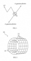
- FIG. 1 is a schematic diagram of a positron annihilation event according to one or more examples of the present disclosure.
- a Fluoro Deoxy Glucose (FDG) marker containing positron radionuclide may be injected as a tracer into a subject. After being injected into the subject, the tracer may spread into different tissues along with blood and participate in metabolism of the subject. During the process, the positron radionuclide in the tracer may release a positron e+.
- FDG Fluoro Deoxy Glucose
- the released positrons e+ may be annihilated with a negatron e- in the surrounding environment and then a pair of gamma-photons having equal energy (e.g., 511 KeV) and opposite propagation direction (e.g., about 180 degrees) may be generated.
- the pair of gamma-photons may be detected by a detector of a PET system. In this way, positron analysis may be carried out and concentration distribution of the tracer in the subject may be obtained.
- FIG. 2 is a schematic diagram of a detector 10 of the PET system according to one or more examples of the present disclosure.
- the detector 10 may include a plurality of detector rings 12 arranged along an axis of the detector.
- Each detector ring 12 may include a plurality of detector modules 14 assembled together.
- the plurality of detector rings 12 may constitute an internal space.
- a gamma-photon pair generated by a positron annihilation event which occurs in the internal space may be detected by a pair of detector modules 14 when the gamma-photon pair is incident on the pair of detector modules 14 along opposite directions.
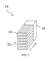
- FIG. 3 is a schematic diagram of the detector module 14 according to one or more examples of the present disclosure.
- Each detector module 14 may include a plurality of crystals 16 and a photoelectric detecting component 18.
- the plurality of crystals 16 may form a crystal array 20.
- a crystal 16 may be a scintillation crystal.
- the crystal 16 may absorb a gamma-photon and produce a number of visible light signals according to the energy of the gamma-photon. Only for illustration, as shown in FIG. 3 , the crystal array 20 is a 6*6 crystal array, which is not limited hereto.
- the crystal array 20 may be configured according to practical applications.
- the photoelectric detecting component 18 may include a photomultiplier to convert visible light signals produced by the crystal 16 into electrical signals to be output.
- the detector module 14 may include one or more photoelectric detecting components 18.
- the electrical signals may be used for coincidence determination, e.g., the electrical signals may be used to determine whether the time at which two gamma-photons are incident into two detector modules 14 is within a preset time window.
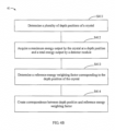
- FIG. 4A is a flow chart of a process 40 of an imaging method according to one or more examples of the present disclosure.
- the imaging method may be applied in a PET system.
- the process 40 may include steps 41 to 46.
- a respective reference energy weighting factor corresponding to each of a plurality of depth positions of a crystal in a detector module is determined. In such a way, correspondences (or associations) between the depth positions of the crystal and the respective reference energy weighting factors can be obtained for the crystal.
- FIG. 4B is a flow chart of an example process performing step 41, which can include steps S411 to S414.
- a depth position of the crystal may indicate its position in a depth direction of the crystal, e.g., x direction as shown in FIG. 3 .
- a simulation model of the PET system may be created by a simulation software (e.g., GATE simulation software) based on a physical structure of the detector module.
- the physical structure of the detector module may include one or more parameters such as, structure, size, arrangement and so on for each crystal in detector module.
- the parameters can be entered into the simulation software to create the simulation model.
- each crystal may be divided into a plurality of levels in the depth direction, and a reference energy weighting factor corresponding to each of the plurality of levels may be determined. It is understood that the deeper the depth of a gamma-photon incident into a crystal is, the more energy loss the gamma-photon experiences. Therefore, the reference energy weighting factor corresponding to each of the plurality of levels may be different.
- each of the plurality of levels may be equal in step length.
- a crystal may be equally divided into N portions in the depth direction, where N is a positive integer greater than 1.
- N is a positive integer greater than 1.
- the depth of a crystal is 20 mm, and the depth may be divided into 5 levels in a step length of 4 mm, e.g., levels at depths of 0 to 4 mm, 4 mm to 8 mm, 8 mm to 12 mm, 12 mm to 16 mm, and 16 mm to 20 mm, respectively.
- a depth position is within one of the depth levels.
- a depth position of 3 mm is within the first depth level of 0 to 4 mm.
- the reference energy weighting factor can be the same as the reference energy weighting factor for the depth level. In some cases, for a depth position in a depth level, the reference energy weighting factor can be determined based on the reference energy weighting factor for the depth level, e.g., based on a function. The smaller the step length is, the more reference energy weighting factors can be obtained for the crystal, and the higher image resolution can be achieved.
- each of the plurality of levels may not be equal in step length or not be exactly equal in step length.
- the depth of a crystal may not be equally divided into levels. For example, it is assumed that the depth of a crystal is 18 mm and the depth may be divided into 5 levels, where a first level is at a depth of 0 to 2 mm, and a second level to a fifth level, which may be divided in the same step length of 4 mm, are at depths of 2 mm to 6 mm, 6 mm to 10 mm, 10 mm to 14 mm, and 14 mm to 18 mm, respectively.
- each of the plurality of levels may also be divided in accordance with a particular regulation.
- each level may be divided in a progressively increasing or decreasing step length between the levels, which is not limited hereto.
- Each of the plurality of levels can also be divided according to a practical application.
- multiple discrete depth positions may be selected and a respective reference energy weighting factor corresponding to each of the multiple discrete depth positions may be determined.
- respective reference energy weighting factors corresponding to multiple continuous depth positions of a crystal may also be determined, e.g., a functional relationship between depth position and reference energy weighting factor for a crystal may be determined.
- the aforementioned plurality of depth positions may include the above multiple discrete depth positions, and may also include the above multiple continuous depth positions.
- the selected depth positions of each crystal in the crystal array may be the same.
- the selected depth positions of one or more crystals in the crystal array may be different.
- a maximum energy E max output by the crystal at a depth position and a total energy E output by the detector module are acquired.
- the single event may be an event that one gamma-photon is incident into one crystal.
- the position information indicates a position where the single event happens, and may be represented by a position of the crystal hit by the gamma-photon of the single event in the crystal array, such as a row number and a column number of the crystal hit by the gamma-photon in the crystal array.
- the position information may be obtained based on a centroid method (e.g., Anger Logic method) or based on an intensity of a signal output by the detector module (e.g., an one-to-one out system).
- the energy information may include the maximum energy E max at each depth level output by the hit crystal and the total energy E collected (or output) by the detector module when the hit crystal outputs the maximum energy E max .
- the total energy E may be collected at each depth level of the hit crystal and a sum of energy output by the whole crystal array, e.g., output by multiple crystals including the hit crystal in the whole crystal array.
- the multiple crystals are associated with the single event.
- the gamma-photon can be incident into each of the multiple crystals in a way that a plurality of single event signals associated with the single event are generated. One of the plurality of single event signals corresponds to one of the multiple crystals.
- the maximum energy E max is a maximum of energy output by the multiple crystals including the hit crystal in the whole crystal array.
- the maximum energy output by a crystal at each depth position may be obtained.
- the maximum energy output by a crystal at each level may be obtained.
- the maximum energy output by the crystal at a level can be considered as the maximum energy output by the crystal at each depth position within in the level.
- a virtual radioactive source e.g., a point radioactive source
- the simulation model may detect the maximum energy E max at each depth level and the total energy E. In this way, by the simulation model, the energy information can be obtained.
- a reference energy weighting factor corresponding to the depth position of the crystal is determined according to the maximum energy E max at the depth position of the crystal and the total energy E output.
- the reference energy weighting factor ⁇ is determined according to the following formula:
- i and j are position information of a crystal and represent a coordinate position of the crystal in the crystal array, where i and j are positive integers greater than or equal to 1.
- i and j may indicate that the crystal is located in the i-th row and the j-th column in the crystal array.
- k may represent the k-th level of the crystal in the depth direction, and k is a positive integer greater than or equal to 1.
- k may represent a depth position, for example, the k-th selected depth position, which is not limited hereto.
- the correspondence between depth position and reference energy weighting factor may be created with the reference energy weighting factor, the position information and the depth position of the crystal.
- an energy weighting factor searching table may be created with the reference energy weighting factor, the position information and the depth position of the crystal. Each depth position of the crystal can be associated with a respective reference energy weighting factor and/or respective position information.
- the energy weighting factor searching table can store associations between crystals and respective position information and associations between depth positions of crystals and respective reference energy weighting factors.
- the operation of the step 41 may be completed offline in advance before an actual scan of the PET system, and the correspondence between depth position and reference energy weighting factor may be created in advance and stored in a storage module (or a repository) in the PET system.
- reference energy weighting factors are determined by simulation modeling. Compared with determining reference energy weighting factors by a test, both workload and cost of the above method of determining reference energy weighting factors by simulation modeling may be significantly reduced.
- single event signals produced in the detector module are received, and the single event signals are generated from one single event (or associated with the single event).
- the single event signals produced in the detector module may be collected.
- a hit crystal corresponding to a maximum single event signal of the single event signals and an actual energy weighting factor of the hit crystal are determined.
- the hit crystal is a crystal hit by a gamma-photon for producing the maximum single event signal.
- FIG. 4C is a flow chart of an example process performing step 43, which can include steps S431 to S433,
- step S431 the hit crystal corresponding to the maximum single event signal of the single event signals is determined.
- the position information of a crystal corresponding to the maximum single event signal output by the detector module at a particular moment may be determined based on the centroid method or a one-to-one output system.
- the position information of the crystal hit by the gamma-photon for producing the maximum single event signal can be determined by the one-to-one output system.
- the one-to-one output system means that the detector module may also include a receiving array, and the receiving array is in a one-to-one correspondence with the crystal array.
- Position information of a crystal is the position of the crystal in the crystal array.
- a gamma-photon may be perpendicularly incident into crystal 1
- the single event signal produced in crystal 1 may be the single event signal having the maximum signal intensity among single event signals produced in the detector module at this moment.
- Crystal 1 may be regarded as a hit crystal in which the single event happens, e.g., a crystal hit by the gamma-photon associated with the single event.
- a gamma-photon when an annihilation event does not happen at the central position of the detector ring, a gamma-photon may be obliquely incident .into one or more crystals.
- the first crystal into which the gamma-photon is incident among the one or more crystals may be regarded as the hit crystal, and the single event signal produced in the crystal has the maximum intensity.
- the gamma-photon may pass through the first crystal and then be incident into a crystal adjacent to the first crystal, and the intensity of the single event signal is relatively low in the crystal adjacent to the first crystal.
- the intensity of a signal produced by acting with the crystal adjacent to the first crystal may also be relatively low.
- the crystal with which the gamma-ray acts in the crystal array of the detector module may be regarded as the first crystal, e.g., the first crystal is the hit crystal.
- the maximum energy output by the hit crystal corresponding to the maximum single event signal and the actual total energy output by the detector module are acquired.
- the actual total energy output by the detector module is a sum of energy output by all crystals of the crystal array when the hit crystal outputs the maximum energy.
- the actual energy weighting factor of the hit crystal is determined according to the maximum energy output by the hit crystal corresponding to the maximum single event signal and the actual total energy. Similar to the reference energy weighting factor, the actual energy weighting factor can be a ratio between the maximum energy output by the hit crystal corresponding to the maximum single event signal and the actual total energy output by the detector module.
- an actual depth position corresponding to the actual energy weighting factor for the hit crystal is determined as an acting position in the detector module for the single event, according to the correspondence between depth position and reference energy weighting factor for the hit crystal.
- a depth position corresponding to the actual energy weighting factor is determined according to the correspondence between depth position and reference energy weighting factor created in the block 41 for the hit crystal.
- a level corresponding to the actual energy weighting factor in the depth direction may be determined.
- An acting depth of the hit crystal can be determined based on the determined level.
- the acting position of the hit crystal for the single event may be determined based on the determined acting depth of the hit crystal.
- a response line of a coincidence event is determined according to respective acting positions in the detector module for two single events constituting the coincidence event.
- Each acting position represents an acting depth in a hit crystal corresponding to one of the two single events.
- a number of single events with corresponding acting depth position information may be output, and it may be determined whether two single events constitute a coincidence event according to the acting depth position information with a coincidence determination principle. For example, two single events with corresponding acting depth position information within a time window can constitute a coincidence event. Then, a response line of the coincidence event is determined according to the position information of a pair of crystals constituting the coincidence event and the depth positions of the gamma-photons in the crystals. In this way, the response line of an actual annihilation event may be obtained.
- an image is reconstructed according to a plurality of response lines including the response line.
- the plurality of response lines of coincidence event may be determined according to the method of the steps 42 to 45.
- an image may be reconstructed according to information of the plurality of response lines.
- the operations of the imaging method 40 are illustrated in a form of steps, but the sequence of each of the steps shown in FIGS. 4A , 4B and 4C and the operations in each of the steps are not limited to the above examples.
- the operations in each of the steps may be carried out in different sequences.
- the operations in one step may be combined with the operation in another step, or divided into a plurality of sub-steps.
- FIG. 5 is a hardware structure diagram of an imaging system according to one or more examples of the present disclosure.
- the imaging system may be a PET system.
- the imaging system may be implemented by software, hardware or a combination of software and hardware. From the hardware level, in addition to a processor 510, a network interface 520, a machine-readable storage medium 530 and an internal bus 540 shown in FIG. 5 , the imaging system may also include other hardware according to actual functions, and further description is omitted for brevity.
- the machine-readable storage medium 530 may be a Read-Only Memory (ROM), a volatile memory, a non-volatile memory, a flash memory, a storage drive (e.g., hard disk drive), a solid state hard disk, any type of storage disk (e.g., optical disk, Digital Video Disk (DVD)), or a similar storage medium, or a combination thereof.
- ROM Read-Only Memory
- volatile memory e.g., volatile memory
- non-volatile memory e.g., a non-volatile memory
- a flash memory e.g., a solid state hard disk, any type of storage disk (e.g., optical disk, Digital Video Disk (DVD)), or a similar storage medium, or a combination thereof.
- DVD Digital Video Disk
- imaging control logic 600 is stored on the machine-readable storage medium 530. As shown in FIG. 6 , divided by functions, the imaging control logic 600 may include: a determining module 610, a processing module 620 and an image reconstructing module 630.
- the determining module 610 may be configured to determine a reference energy weighting factor corresponding to each of a plurality of depth positions of a crystal in a detector module, and a correspondence between depth position and reference energy weighting factor with the reference energy weighting factor corresponding to each of the depth positions of the crystal in the detector module.
- the determining module 610 may be configured to divide the crystal in the detector module into a plurality of levels along a depth direction, and determine the correspondence between depth position and reference energy weighting factor with the reference energy weighting factor corresponding to each of the plurality of levels.
- the determining module 610 may be further configured to acquire a maximum energy output by the crystal at the depth position; acquire a total energy output by the detector module when the crystal outputs the maximum energy; and determine the reference energy weighting factor corresponding to the crystal at the depth position according to the maximum energy and the total energy.
- the determining module 610 may include a depth position determining sub-module, a reference energy weighting factor generating sub-module and a correspondence creating sub-module.
- the depth position determining sub-module may be configured to determine the plurality of depth positions of the crystal.
- the depth position determining sub-module 611 may be configured to perform depth simulation modelling and divide the crystal into a plurality of levels in the depth direction based on the simulation model.
- the depth position determining sub-module may be further configured to obtain position information and energy information of single events received at different depth positions by the detector module.
- the position information and the energy information of the single events may be obtained by an information identifying sub-module.
- the information identifying sub-module and the depth position determining sub-module are modules independent of each other.
- the reference energy weighting factor generating sub-module may be configured to obtain a maximum energy E max output by the crystal at a depth position and a total energy E output by the detector module, and determine a reference energy weighting factor corresponding to the depth position of the crystal according to the maximum energy E max at the depth position of the crystal and the total energy E.
- energy information and/or position information of the single events received at different depth positions by the detector module may be obtained by the reference energy weighting factor generating sub-module.
- the correspondence creating sub-module may be configured to create the correspondence between depth position and reference energy weighting factor with the reference energy weighting factor, the position information and the depth position of the crystal.
- the processing module 620 may be configured to receive single event signals produced in the detector module; determine a hit crystal corresponding to a maximum single event signal of the single event signals and an actual energy weighting factor of the hit crystal; determine an actual depth position corresponding to the actual energy weighting factor of the hit crystal, according to the correspondence between depth position and reference energy weighting factor, as an acting position in the detector module for a single event corresponding to the maximum single event signal; and determine a response line of a coincidence event according to respective acting positions in the detector module for two single events constituting the coincidence event.
- the imaging system as shown in FIG. 5 may also include a detector ring (not shown in FIG. 5 ), and the detector ring includes the plurality of detector modules 14.
- Each detector module 14 includes the plurality of crystals 16.
- FIG. 7 is a schematic diagram of a detector ring according to one or more examples of the present disclosure. A pair of crystals denoted by reference numerals 17 and 19 in FIG. 7 is a pair of hit crystals.
- the processing module 620 may be configured to perform the steps 42 to 45 of the aforementioned imaging method 40.
- the processing module 620 may be configured to obtain a maximum energy output by the hit crystal 17 and an actual total energy output by the detector module 14 when the hit crystal 17 outputs the maximum energy, and determine an actual energy weighting factor of the hit crystal 17 according to the maximum energy output by the hit crystal 17 and the actual total energy when the hit crystal 17 outputs the maximum energy.
- the processing module 620 may be further configured to obtain a maximum energy output by the hit crystal 19 and an actual total energy output by the detector module 14 when the hit crystal 19 outputs the maximum energy, and determine an actual energy weighting factor of the hit crystal 19 according to the maximum energy output by the hit crystal 19 and the actual total energy when the hit crystal 19 outputs the maximum energy.
- the processing module 620 includes a data collecting module, an information identifying module, an actual energy weighting factor generating module, an energy weighting factor searching module and a coincidence determining module.
- the data collecting module may be configured to collect (or receive) single event signals output by the detector module during an actual scan.
- the information identifying module may be configured to determine the position information of the hit crystal. In one or more examples, the information identifying module may be further configured to determine energy information of the maximum energy output by the hit crystal and the actual total energy. In one or more examples, the information identifying module may include a position information identifying module for obtaining the position information and an energy information identifying module for obtaining the energy information.
- the actual energy weighting factor generating module may be configured to obtain an actual energy weighting factor according to the maximum energy output by the hit crystal and the actual total energy.
- the energy information of the maximum energy output by the hit crystal and the actual total energy may be determined by the actual energy weighting factor generating module.
- the energy weighting factor searching module may be configured to search for the depth position of the hit crystal corresponding to the actual energy weighting factor in the correspondence between depth position and reference energy weighting factor.
- the coincidence determining module may be configured to determine whether single events happening in a pair of crystals constitute a coincidence event. If so, the line connecting the depth positions of the pair of hit crystals 17 and 19 is determined as a response line 54 of the coincidence event. The annihilation event 56 occurs on the response line 54.
- the image reconstructing module 630 may be configured to reconstruct an image according to a plurality of response lines.
- the imaging control logic in the present disclosure should be interpreted as machine-executable instructions stored on the machine-readable storage medium 530.
- the processor 510 in the imaging system of the present disclosure executes the control logic
- the processor 510 executes the above-described imaging method by invoking machine-executable instructions corresponding to the control logic stored on the machine-readable storage medium 530.
- the present disclosure further provides a machine-readable storage medium including machine-executable instructions, for example, the machine-readable storage medium 530 shown in FIG. 5 .
- the machine executable instructions may be executed by the processor 510 in the imaging system to perform the above-described imaging method.
- the correlations therebetween may refer to part of the method examples.
- the system examples described above are merely illustrative, wherein units described as separate components may be or may not be physically separated, and components displayed as units may be or may not be physical units, i.e., may be located in one place, or may be distributed to a plurality of network elements. Part or all of the modules may be selected according to actual requirements to achieve the purpose of the solution of the present disclosure. Those skilled in the art will understand and implement it without creative work.
Landscapes
- Health & Medical Sciences (AREA)
- Life Sciences & Earth Sciences (AREA)
- Engineering & Computer Science (AREA)
- Medical Informatics (AREA)
- Physics & Mathematics (AREA)
- High Energy & Nuclear Physics (AREA)
- Molecular Biology (AREA)
- Optics & Photonics (AREA)
- General Health & Medical Sciences (AREA)
- Biomedical Technology (AREA)
- Nuclear Medicine, Radiotherapy & Molecular Imaging (AREA)
- Pathology (AREA)
- Public Health (AREA)
- Radiology & Medical Imaging (AREA)
- Veterinary Medicine (AREA)
- Heart & Thoracic Surgery (AREA)
- Surgery (AREA)
- Animal Behavior & Ethology (AREA)
- Biophysics (AREA)
- General Physics & Mathematics (AREA)
- Spectroscopy & Molecular Physics (AREA)
- Computer Vision & Pattern Recognition (AREA)
- Mathematical Physics (AREA)
- Measurement Of Radiation (AREA)
- Nuclear Medicine (AREA)
Claims (7)
- Bilderzeugungsverfahren, das umfasst:Generieren eines Simulationsmodells auf Basis einer physikalischen Struktur eines Detektor-Moduls (14);für jeden von in dem Detektor-Modul (14) enthaltenen Kristallen:
Bestimmen eines Referenz-Energiegewichtsfaktors entsprechend jeder einer Vielzahl von Tiefenpositionen des Kristalls auf Basis des erzeugten Simulationsmodells, wobei Bestimmen des der Tiefenposition des Kristalls entsprechenden Referenz-Energiegewichtsfaktors umfasst:Erfassen einer maximalen Energie, die von dem Kristall an der Tiefenposition ausgegeben wird; Erfassen einer Gesamtenergie, die von dem Detektor-Modul (14) ausgegeben wird, wenn der Kristall die maximale Energie ausgibt; und Bestimmen des dem Kristall an der Tiefenposition entsprechenden Referenz-Energiegewichtsfaktors gemäß einem Verhältnis zwischen der maximalen Energie und der Gesamtenergie;Bestimmen von Beziehungen zwischen der Vielzahl von Tiefenpositionen des Kristalls und den bestimmten jeweiligen Referenz-Energiegewichtsfaktoren für den Kristall;Empfangen von Einzelereignis-Signalen, die in dem Detektor-Modul (14) erzeugt werden und mit einem Einzelereignis zusammenhängen;Bestimmen eines getroffenen Kristalls in dem Detektor-Modul (14) entsprechend einem maximalen Einzelereignis-Signal der Einzelereignis-Signale;Bestimmen eines Ist-Energiegewichtsfaktors des getroffenen Kristalls, wobei Bestimmen des Ist-Energiegewichtsfaktors umfasst:Ermitteln einer maximalen Energie, die von den getroffenen Kristall ausgegeben wird; Ermitteln einer Ist-Gesamtenergie, die von dem Detektor-Modul (14) ausgegeben wird, wenn der getroffene Kristall die maximale Energie ausgibt; und Bestimmen des Ist-Energiegewichtsfaktors des getroffenen Kristalls gemäß der maximalen Energie, die von dem getroffenen Kristall ausgegeben wird, sowie der Ist-Gesamtenergie, die von dem Detektor-Modul (14) ausgegeben wird;Bestimmen einer Ist-Tiefenposition, die dem Ist-Energiegewichtsfaktor des getroffenen Kristalls entspricht, entsprechend den Verbindungen zwischen den Tiefenpositionen des getroffenen Kristalls und den jeweiligen Referenz-Energiegewichtsfaktoren für den getroffenen Kristall als eine Wirkposition in dem Detektor-Modul (14) für das Einzelereignis;Bestimmen einer Reaktions-Linie (response line) eines Koinzidenz-Ereignisses gemäß den jeweiligen Wirkpositionen in dem Detektor-Modul (14) für zwei Einzelereignisse, die das Koinzidenz-Ereignis bilden, wobei die zwei Einzelereignisse das Einzelereignis einschließen; undRekonstruieren eines Bildes entsprechend der Reaktions-Linie. - Bilderzeugungsverfahren nach Anspruch 1, wobei Bestimmen des getroffenen Kristalls umfasst:Bestimmen von Positionsinformationen des getroffenen Kristalls, die dem maximalen Einzelereignis-Signal entsprechen, das von dem Detektor-Modul (14) ausgegeben wird; sowieBestimmen des getroffenen Kristalls für das Einzelereignis auf Basis der bestimmten Positionsinformationen.
- Bilderzeugungsverfahren nach Anspruch 1, das des Weiteren umfasst:
Speichern der jeweiligen Verbindungen für die Vielzahl von Kristallen in einem Speicher. - Bilderzeugungsverfahren nach Anspruch 1, wobei Bestimmen des jeweiligen jeder der Vielzahl von Tiefenpositionen entsprechenden Referenz-Energiegewichtsfaktors auf Basis des erzeugten Simulationsmodells umfasst:Unterteilen des Kristalls in eine Vielzahl von Tiefenebenen in einer Tiefenrichtung des Kristalls auf Basis des Simulationsmodells;Bestimmen eines Referenz-Energiegewichtsfaktors, der jeder der Vielzahl von Tiefenebenen entspricht; sowieBestimmen des jeweiligen einer der Tiefenpositionen entsprechenden Referenz-Energiegewichtsfaktors auf Basis des bestimmten Referenz-Energiegewichtsfaktors einer Tiefenebene, die die eine der Tiefenpositionen einschließt.
- Bilderzeugungsverfahren nach Anspruch 4, wobei Bestimmen des jeder der Vielzahl von Tiefenebenen entsprechenden Referenz-Energiegewichtsfaktors umfasst:Erfassen einer maximalen Energie, die von dem Kristall in der Tiefenebene ausgegeben wird;Erfassen einer Gesamtenergie, die von dem Detektor-Modul (14) ausgegeben wird, wenn der Kristall die maximale Energie ausgibt; sowieBestimmen des dem Kristall in der Tiefenebene entsprechenden Referenz-Energiegewichtsfaktors, entsprechend der maximalen Energie und der Gesamtenergie.
- Bilderzeugungsverfahren nach Anspruch 1, das des Weiteren umfasst:Bestimmen einer Vielzahl von Einzelereignissen mit entsprechenden Wirkpositionen; sowieFeststellen, ob zwei Einzelereignisse ein Koinzidenz-Ereignis bilden, gemäß den entsprechenden Wirk-Tiefenpositionen mit einem Prinzip für Bestimmung von Koinzidenz.
- Bilderzeugungssystem, das umfasst:einen Prozessor (510); sowieein maschinenlesbares Speichermedium (530),wobei durch Lesen und Ausführen maschinenausführbarer Befehle, die auf dem maschinenlesbaren Speichermedium (530) gespeicherter Bilderzeugungs-Logik entsprechen, der Prozessor (510) veranlasst wird, das Verfahren nach einem der Ansprüche 1 bis 6 durchzuführen.
Applications Claiming Priority (1)
| Application Number | Priority Date | Filing Date | Title |
|---|---|---|---|
| CN201610925903.XA CN107970037B (zh) | 2016-10-24 | 2016-10-24 | 成像方法和成像系统 |
Publications (2)
| Publication Number | Publication Date |
|---|---|
| EP3316002A1 EP3316002A1 (de) | 2018-05-02 |
| EP3316002B1 true EP3316002B1 (de) | 2024-08-21 |
Family
ID=60201331
Family Applications (1)
| Application Number | Title | Priority Date | Filing Date |
|---|---|---|---|
| EP17197959.4A Active EP3316002B1 (de) | 2016-10-24 | 2017-10-24 | Bestimmung von antwortzeilen zur bildrekonstruktion |
Country Status (3)
| Country | Link |
|---|---|
| US (1) | US10064587B2 (de) |
| EP (1) | EP3316002B1 (de) |
| CN (1) | CN107970037B (de) |
Families Citing this family (8)
| Publication number | Priority date | Publication date | Assignee | Title |
|---|---|---|---|---|
| WO2014074666A1 (en) * | 2012-11-07 | 2014-05-15 | Massachusetts Institute Of Technology | Inter-detector scatter enhanced emission tomography |
| CN107595315A (zh) * | 2017-09-30 | 2018-01-19 | 华中科技大学 | 一种发射成像设备中光响应线的获取方法 |
| CN109009197B (zh) * | 2018-08-06 | 2020-07-07 | 南京航空航天大学 | 一种用于pet检测的双晶体条穿越符合响应线检测系统和方法 |
| CN109521459B (zh) * | 2018-12-07 | 2020-08-25 | 深圳先进技术研究院 | 一种射线在闪烁晶体中的击中点定位方法及其系统 |
| CN110664423B (zh) * | 2019-09-12 | 2023-05-09 | 沈阳智核医疗科技有限公司 | 成像方法、装置、探测器、终端设备和pet系统 |
| CN113835113B (zh) * | 2021-09-23 | 2023-10-10 | 明峰医疗系统股份有限公司 | 一种pet中的模块间散射数据收集方法 |
| CN115081230A (zh) * | 2022-07-01 | 2022-09-20 | 上海联影医疗科技股份有限公司 | 一种扫描过程中死时间的校正方法和系统 |
| CN117503173A (zh) * | 2022-07-29 | 2024-02-06 | 上海联影医疗科技股份有限公司 | 一种医学成像的系统、方法、装置和存储介质 |
Family Cites Families (9)
| Publication number | Priority date | Publication date | Assignee | Title |
|---|---|---|---|---|
| US20040164249A1 (en) * | 2003-02-26 | 2004-08-26 | Crosetto Dario B. | Method and apparatus for determining depth of interactions in a detector for three-dimensional complete body screening |
| JP2010032214A (ja) * | 2007-04-23 | 2010-02-12 | Natl Inst Of Radiological Sciences | エネルギーと位置情報を利用した放射線検出方法及び装置 |
| JP2010249672A (ja) * | 2009-04-16 | 2010-11-04 | Toshiba Corp | ポジトロンct装置 |
| CN102755172B (zh) * | 2011-04-28 | 2015-01-28 | 株式会社东芝 | 核医学成像方法以及核医学成像装置 |
| US8816286B2 (en) * | 2011-08-01 | 2014-08-26 | Siemens Medical Solutions Usa, Inc. | Optical simulation-based time-of-flight compensation and PET system configuration |
| WO2013054300A2 (en) * | 2011-10-12 | 2013-04-18 | Koninklijke Philips Electronics N.V. | Modelling of tof-doi detector arrays |
| WO2016002084A1 (ja) * | 2014-07-04 | 2016-01-07 | 株式会社島津製作所 | 画像再構成処理方法 |
| CN105769229B (zh) * | 2014-12-24 | 2018-08-03 | 沈阳东软医疗系统有限公司 | 一种计算pet系统半径扩大值的方法、图像重建方法及装置 |
| US10261201B2 (en) * | 2016-04-04 | 2019-04-16 | General Electric Company | Method for improving timing resolution using depth of interaction correction in PET detector |
-
2016
- 2016-10-24 CN CN201610925903.XA patent/CN107970037B/zh not_active Expired - Fee Related
-
2017
- 2017-10-23 US US15/790,510 patent/US10064587B2/en active Active
- 2017-10-24 EP EP17197959.4A patent/EP3316002B1/de active Active
Non-Patent Citations (2)
| Title |
|---|
| LING T ET AL: "Depth of interaction decoding of a continuous crystal detector module", PHYSICS IN MEDICINE AND BIOLOGY, INSTITUTE OF PHYSICS PUBLISHING, BRISTOL GB, vol. 52, no. 8, 21 April 2007 (2007-04-21), pages 2213 - 2228, XP020113288, ISSN: 0031-9155, DOI: 10.1088/0031-9155/52/8/012 * |
| ROGERS J G: "A METHOD FOR CORRECTING THE DEPTH-OF-INTERACTION BLURRING IN PET CAMERAS", IEEE TRANSACTIONS ON MEDICAL IMAGING, IEEE, USA, vol. 14, no. 1, 1 March 1995 (1995-03-01), pages 146 - 150, XP000507932, ISSN: 0278-0062, DOI: 10.1109/42.370411 * |
Also Published As
| Publication number | Publication date |
|---|---|
| EP3316002A1 (de) | 2018-05-02 |
| US20180110482A1 (en) | 2018-04-26 |
| CN107970037A (zh) | 2018-05-01 |
| CN107970037B (zh) | 2021-01-05 |
| US10064587B2 (en) | 2018-09-04 |
Similar Documents
| Publication | Publication Date | Title |
|---|---|---|
| US10064587B2 (en) | Determining response lines for image reconstruction | |
| US10360699B2 (en) | Correcting count loss | |
| US7888651B2 (en) | Method and system for using tissue-scattered coincidence photons for imaging | |
| Hutton et al. | Review and current status of SPECT scatter correction | |
| JP5174813B2 (ja) | Tofpetの再構成を改良するための方法及びシステム | |
| US10535165B2 (en) | Reconstructing image | |
| CN105125231B (zh) | 一种pet图像环状伪影的去除方法和装置 | |
| Lewellen | The challenge of detector designs for PET | |
| CN106415317B (zh) | 单光子发射计算机化断层摄影术中的多个发射能量 | |
| US10852448B2 (en) | Dead pixel correction for digital PET reconstruction | |
| Fukuchi et al. | Positron emission tomography with additional γ‐ray detectors for multiple‐tracer imaging | |
| CN109887048A (zh) | Pet散射校正方法、图像重建方法、装置及电子设备 | |
| Ahmed et al. | A validated Geant4 model of a whole-body PET scanner with four-layer DOI detectors | |
| Alenazy et al. | New solid state cadmium-zinc-telluride technology for cardiac single photon emission computed tomographic myocardial perfusion imaging | |
| CN106859686B (zh) | 成像方法和成像系统 | |
| CA2230470A1 (en) | An imaging apparatus | |
| CN112932513A (zh) | 一种医学成像系统 | |
| Li | Novel PET systems and image reconstruction with actively controlled geometry | |
| Fahey | Instrumentation in positron emission tomography | |
| Mejia et al. | Methodological approaches to planar and volumetric scintigraphic imaging of small volume targets with high spatial resolution and sensitivity | |
| Wei | Development of PET Imaging Technologies for Organ-Specific Applications | |
| Juma | Lesion Synthesis Toolbox: Development and validation of dedicated software for synthesis of lesions in raw PET and CT patient images | |
| Arias Valcayo | Métodos avanzados de reconstrucción y procesamiento dedatos en tomografía por emisión de positrones | |
| Kikuchi et al. | PET-Compton hybrid imaging simulation of a small animal whole-gamma-imaging system | |
| Kalaitzidis | From Monte Carlo PET Simulations to Reconstructed Images: Modelling and Optimisation for 68 Ga Theragnostics |
Legal Events
| Date | Code | Title | Description |
|---|---|---|---|
| PUAI | Public reference made under article 153(3) epc to a published international application that has entered the european phase |
Free format text: ORIGINAL CODE: 0009012 |
|
| STAA | Information on the status of an ep patent application or granted ep patent |
Free format text: STATUS: REQUEST FOR EXAMINATION WAS MADE |
|
| 17P | Request for examination filed |
Effective date: 20171024 |
|
| AK | Designated contracting states |
Kind code of ref document: A1 Designated state(s): AL AT BE BG CH CY CZ DE DK EE ES FI FR GB GR HR HU IE IS IT LI LT LU LV MC MK MT NL NO PL PT RO RS SE SI SK SM TR |
|
| AX | Request for extension of the european patent |
Extension state: BA ME |
|
| RBV | Designated contracting states (corrected) |
Designated state(s): AL AT BE BG CH CY CZ DE DK EE ES FI FR GB GR HR HU IE IS IT LI LT LU LV MC MK MT NL NO PL PT RO RS SE SI SK SM TR |
|
| STAA | Information on the status of an ep patent application or granted ep patent |
Free format text: STATUS: EXAMINATION IS IN PROGRESS |
|
| 17Q | First examination report despatched |
Effective date: 20200506 |
|
| RAP3 | Party data changed (applicant data changed or rights of an application transferred) |
Owner name: NEUSOFT MEDICAL SYSTEMS CO., LTD. |
|
| RIN1 | Information on inventor provided before grant (corrected) |
Inventor name: ZHAO, JIAN Inventor name: LI, NAN Inventor name: WU, GUOCHENG Inventor name: LIANG, GUODONG |
|
| RAP1 | Party data changed (applicant data changed or rights of an application transferred) |
Owner name: SHENYANG INTELLIGENT NEUCLEAR MEDICAL TECHNOLOGY CO., LTD. |
|
| GRAP | Despatch of communication of intention to grant a patent |
Free format text: ORIGINAL CODE: EPIDOSNIGR1 |
|
| STAA | Information on the status of an ep patent application or granted ep patent |
Free format text: STATUS: GRANT OF PATENT IS INTENDED |
|
| INTG | Intention to grant announced |
Effective date: 20240326 |
|
| GRAS | Grant fee paid |
Free format text: ORIGINAL CODE: EPIDOSNIGR3 |
|
| GRAA | (expected) grant |
Free format text: ORIGINAL CODE: 0009210 |
|
| STAA | Information on the status of an ep patent application or granted ep patent |
Free format text: STATUS: THE PATENT HAS BEEN GRANTED |
|
| AK | Designated contracting states |
Kind code of ref document: B1 Designated state(s): AL AT BE BG CH CY CZ DE DK EE ES FI FR GB GR HR HU IE IS IT LI LT LU LV MC MK MT NL NO PL PT RO RS SE SI SK SM TR |
|
| REG | Reference to a national code |
Ref country code: GB Ref legal event code: FG4D |
|
| REG | Reference to a national code |
Ref country code: CH Ref legal event code: EP |
|
| REG | Reference to a national code |
Ref country code: DE Ref legal event code: R096 Ref document number: 602017084214 Country of ref document: DE |
|
| REG | Reference to a national code |
Ref country code: IE Ref legal event code: FG4D Ref country code: NL Ref legal event code: FP |
|
| REG | Reference to a national code |
Ref country code: LT Ref legal event code: MG9D |
|
| PG25 | Lapsed in a contracting state [announced via postgrant information from national office to epo] |
Ref country code: NO Free format text: LAPSE BECAUSE OF FAILURE TO SUBMIT A TRANSLATION OF THE DESCRIPTION OR TO PAY THE FEE WITHIN THE PRESCRIBED TIME-LIMIT Effective date: 20241121 |
|
| REG | Reference to a national code |
Ref country code: AT Ref legal event code: MK05 Ref document number: 1716035 Country of ref document: AT Kind code of ref document: T Effective date: 20240821 |
|
| PG25 | Lapsed in a contracting state [announced via postgrant information from national office to epo] |
Ref country code: GR Free format text: LAPSE BECAUSE OF FAILURE TO SUBMIT A TRANSLATION OF THE DESCRIPTION OR TO PAY THE FEE WITHIN THE PRESCRIBED TIME-LIMIT Effective date: 20241122 Ref country code: PL Free format text: LAPSE BECAUSE OF FAILURE TO SUBMIT A TRANSLATION OF THE DESCRIPTION OR TO PAY THE FEE WITHIN THE PRESCRIBED TIME-LIMIT Effective date: 20240821 Ref country code: FI Free format text: LAPSE BECAUSE OF FAILURE TO SUBMIT A TRANSLATION OF THE DESCRIPTION OR TO PAY THE FEE WITHIN THE PRESCRIBED TIME-LIMIT Effective date: 20240821 Ref country code: PT Free format text: LAPSE BECAUSE OF FAILURE TO SUBMIT A TRANSLATION OF THE DESCRIPTION OR TO PAY THE FEE WITHIN THE PRESCRIBED TIME-LIMIT Effective date: 20241223 |
|
| PG25 | Lapsed in a contracting state [announced via postgrant information from national office to epo] |
Ref country code: BG Free format text: LAPSE BECAUSE OF FAILURE TO SUBMIT A TRANSLATION OF THE DESCRIPTION OR TO PAY THE FEE WITHIN THE PRESCRIBED TIME-LIMIT Effective date: 20240821 |
|
| PG25 | Lapsed in a contracting state [announced via postgrant information from national office to epo] |
Ref country code: LV Free format text: LAPSE BECAUSE OF FAILURE TO SUBMIT A TRANSLATION OF THE DESCRIPTION OR TO PAY THE FEE WITHIN THE PRESCRIBED TIME-LIMIT Effective date: 20240821 |
|
| PG25 | Lapsed in a contracting state [announced via postgrant information from national office to epo] |
Ref country code: AT Free format text: LAPSE BECAUSE OF FAILURE TO SUBMIT A TRANSLATION OF THE DESCRIPTION OR TO PAY THE FEE WITHIN THE PRESCRIBED TIME-LIMIT Effective date: 20240821 Ref country code: IS Free format text: LAPSE BECAUSE OF FAILURE TO SUBMIT A TRANSLATION OF THE DESCRIPTION OR TO PAY THE FEE WITHIN THE PRESCRIBED TIME-LIMIT Effective date: 20241221 |
|
| PG25 | Lapsed in a contracting state [announced via postgrant information from national office to epo] |
Ref country code: HR Free format text: LAPSE BECAUSE OF FAILURE TO SUBMIT A TRANSLATION OF THE DESCRIPTION OR TO PAY THE FEE WITHIN THE PRESCRIBED TIME-LIMIT Effective date: 20240821 |
|
| PG25 | Lapsed in a contracting state [announced via postgrant information from national office to epo] |
Ref country code: ES Free format text: LAPSE BECAUSE OF FAILURE TO SUBMIT A TRANSLATION OF THE DESCRIPTION OR TO PAY THE FEE WITHIN THE PRESCRIBED TIME-LIMIT Effective date: 20240821 Ref country code: RS Free format text: LAPSE BECAUSE OF FAILURE TO SUBMIT A TRANSLATION OF THE DESCRIPTION OR TO PAY THE FEE WITHIN THE PRESCRIBED TIME-LIMIT Effective date: 20241121 |
|
| PG25 | Lapsed in a contracting state [announced via postgrant information from national office to epo] |
Ref country code: RS Free format text: LAPSE BECAUSE OF FAILURE TO SUBMIT A TRANSLATION OF THE DESCRIPTION OR TO PAY THE FEE WITHIN THE PRESCRIBED TIME-LIMIT Effective date: 20241121 Ref country code: PT Free format text: LAPSE BECAUSE OF FAILURE TO SUBMIT A TRANSLATION OF THE DESCRIPTION OR TO PAY THE FEE WITHIN THE PRESCRIBED TIME-LIMIT Effective date: 20241223 Ref country code: PL Free format text: LAPSE BECAUSE OF FAILURE TO SUBMIT A TRANSLATION OF THE DESCRIPTION OR TO PAY THE FEE WITHIN THE PRESCRIBED TIME-LIMIT Effective date: 20240821 Ref country code: NO Free format text: LAPSE BECAUSE OF FAILURE TO SUBMIT A TRANSLATION OF THE DESCRIPTION OR TO PAY THE FEE WITHIN THE PRESCRIBED TIME-LIMIT Effective date: 20241121 Ref country code: LV Free format text: LAPSE BECAUSE OF FAILURE TO SUBMIT A TRANSLATION OF THE DESCRIPTION OR TO PAY THE FEE WITHIN THE PRESCRIBED TIME-LIMIT Effective date: 20240821 Ref country code: IS Free format text: LAPSE BECAUSE OF FAILURE TO SUBMIT A TRANSLATION OF THE DESCRIPTION OR TO PAY THE FEE WITHIN THE PRESCRIBED TIME-LIMIT Effective date: 20241221 Ref country code: HR Free format text: LAPSE BECAUSE OF FAILURE TO SUBMIT A TRANSLATION OF THE DESCRIPTION OR TO PAY THE FEE WITHIN THE PRESCRIBED TIME-LIMIT Effective date: 20240821 Ref country code: GR Free format text: LAPSE BECAUSE OF FAILURE TO SUBMIT A TRANSLATION OF THE DESCRIPTION OR TO PAY THE FEE WITHIN THE PRESCRIBED TIME-LIMIT Effective date: 20241122 Ref country code: FI Free format text: LAPSE BECAUSE OF FAILURE TO SUBMIT A TRANSLATION OF THE DESCRIPTION OR TO PAY THE FEE WITHIN THE PRESCRIBED TIME-LIMIT Effective date: 20240821 Ref country code: ES Free format text: LAPSE BECAUSE OF FAILURE TO SUBMIT A TRANSLATION OF THE DESCRIPTION OR TO PAY THE FEE WITHIN THE PRESCRIBED TIME-LIMIT Effective date: 20240821 Ref country code: BG Free format text: LAPSE BECAUSE OF FAILURE TO SUBMIT A TRANSLATION OF THE DESCRIPTION OR TO PAY THE FEE WITHIN THE PRESCRIBED TIME-LIMIT Effective date: 20240821 Ref country code: AT Free format text: LAPSE BECAUSE OF FAILURE TO SUBMIT A TRANSLATION OF THE DESCRIPTION OR TO PAY THE FEE WITHIN THE PRESCRIBED TIME-LIMIT Effective date: 20240821 |
|
| PG25 | Lapsed in a contracting state [announced via postgrant information from national office to epo] |
Ref country code: RO Free format text: LAPSE BECAUSE OF FAILURE TO SUBMIT A TRANSLATION OF THE DESCRIPTION OR TO PAY THE FEE WITHIN THE PRESCRIBED TIME-LIMIT Effective date: 20240821 Ref country code: SM Free format text: LAPSE BECAUSE OF FAILURE TO SUBMIT A TRANSLATION OF THE DESCRIPTION OR TO PAY THE FEE WITHIN THE PRESCRIBED TIME-LIMIT Effective date: 20240821 Ref country code: DK Free format text: LAPSE BECAUSE OF FAILURE TO SUBMIT A TRANSLATION OF THE DESCRIPTION OR TO PAY THE FEE WITHIN THE PRESCRIBED TIME-LIMIT Effective date: 20240821 |
|
| PG25 | Lapsed in a contracting state [announced via postgrant information from national office to epo] |
Ref country code: EE Free format text: LAPSE BECAUSE OF FAILURE TO SUBMIT A TRANSLATION OF THE DESCRIPTION OR TO PAY THE FEE WITHIN THE PRESCRIBED TIME-LIMIT Effective date: 20240821 |
|
| PG25 | Lapsed in a contracting state [announced via postgrant information from national office to epo] |
Ref country code: CZ Free format text: LAPSE BECAUSE OF FAILURE TO SUBMIT A TRANSLATION OF THE DESCRIPTION OR TO PAY THE FEE WITHIN THE PRESCRIBED TIME-LIMIT Effective date: 20240821 |
|
| PG25 | Lapsed in a contracting state [announced via postgrant information from national office to epo] |
Ref country code: SK Free format text: LAPSE BECAUSE OF FAILURE TO SUBMIT A TRANSLATION OF THE DESCRIPTION OR TO PAY THE FEE WITHIN THE PRESCRIBED TIME-LIMIT Effective date: 20240821 Ref country code: IT Free format text: LAPSE BECAUSE OF FAILURE TO SUBMIT A TRANSLATION OF THE DESCRIPTION OR TO PAY THE FEE WITHIN THE PRESCRIBED TIME-LIMIT Effective date: 20240821 |
|
| REG | Reference to a national code |
Ref country code: DE Ref legal event code: R097 Ref document number: 602017084214 Country of ref document: DE |
|
| REG | Reference to a national code |
Ref country code: CH Ref legal event code: PL |
|
| PLBE | No opposition filed within time limit |
Free format text: ORIGINAL CODE: 0009261 |
|
| STAA | Information on the status of an ep patent application or granted ep patent |
Free format text: STATUS: NO OPPOSITION FILED WITHIN TIME LIMIT |
|
| PG25 | Lapsed in a contracting state [announced via postgrant information from national office to epo] |
Ref country code: MC Free format text: LAPSE BECAUSE OF FAILURE TO SUBMIT A TRANSLATION OF THE DESCRIPTION OR TO PAY THE FEE WITHIN THE PRESCRIBED TIME-LIMIT Effective date: 20240821 |
|
| PG25 | Lapsed in a contracting state [announced via postgrant information from national office to epo] |
Ref country code: BE Free format text: LAPSE BECAUSE OF NON-PAYMENT OF DUE FEES Effective date: 20241031 Ref country code: LU Free format text: LAPSE BECAUSE OF NON-PAYMENT OF DUE FEES Effective date: 20241024 |
|
| PG25 | Lapsed in a contracting state [announced via postgrant information from national office to epo] |
Ref country code: CH Free format text: LAPSE BECAUSE OF NON-PAYMENT OF DUE FEES Effective date: 20241031 |
|
| 26N | No opposition filed |
Effective date: 20250522 |
|
| REG | Reference to a national code |
Ref country code: BE Ref legal event code: MM Effective date: 20241031 |
|
| PG25 | Lapsed in a contracting state [announced via postgrant information from national office to epo] |
Ref country code: SE Free format text: LAPSE BECAUSE OF FAILURE TO SUBMIT A TRANSLATION OF THE DESCRIPTION OR TO PAY THE FEE WITHIN THE PRESCRIBED TIME-LIMIT Effective date: 20240821 |
|
| PG25 | Lapsed in a contracting state [announced via postgrant information from national office to epo] |
Ref country code: IE Free format text: LAPSE BECAUSE OF NON-PAYMENT OF DUE FEES Effective date: 20241024 |
|
| PGFP | Annual fee paid to national office [announced via postgrant information from national office to epo] |
Ref country code: NL Payment date: 20251024 Year of fee payment: 9 |
|
| PGFP | Annual fee paid to national office [announced via postgrant information from national office to epo] |
Ref country code: DE Payment date: 20251023 Year of fee payment: 9 |
|
| PGFP | Annual fee paid to national office [announced via postgrant information from national office to epo] |
Ref country code: GB Payment date: 20251010 Year of fee payment: 9 |
|
| PGFP | Annual fee paid to national office [announced via postgrant information from national office to epo] |
Ref country code: FR Payment date: 20251010 Year of fee payment: 9 |
|
| PG25 | Lapsed in a contracting state [announced via postgrant information from national office to epo] |
Ref country code: CY Free format text: LAPSE BECAUSE OF FAILURE TO SUBMIT A TRANSLATION OF THE DESCRIPTION OR TO PAY THE FEE WITHIN THE PRESCRIBED TIME-LIMIT; INVALID AB INITIO Effective date: 20171024 |
|
| PG25 | Lapsed in a contracting state [announced via postgrant information from national office to epo] |
Ref country code: HU Free format text: LAPSE BECAUSE OF FAILURE TO SUBMIT A TRANSLATION OF THE DESCRIPTION OR TO PAY THE FEE WITHIN THE PRESCRIBED TIME-LIMIT; INVALID AB INITIO Effective date: 20171024 |