EP3315954B1 - Messgerät zur bestimmung einer eigenschaft eines mediums - Google Patents
Messgerät zur bestimmung einer eigenschaft eines mediums Download PDFInfo
- Publication number
- EP3315954B1 EP3315954B1 EP17196829.0A EP17196829A EP3315954B1 EP 3315954 B1 EP3315954 B1 EP 3315954B1 EP 17196829 A EP17196829 A EP 17196829A EP 3315954 B1 EP3315954 B1 EP 3315954B1
- Authority
- EP
- European Patent Office
- Prior art keywords
- signal
- medium
- excitation
- measuring
- measuring device
- Prior art date
- Legal status (The legal status is an assumption and is not a legal conclusion. Google has not performed a legal analysis and makes no representation as to the accuracy of the status listed.)
- Active
Links
Images

Classifications
-
- G—PHYSICS
- G01—MEASURING; TESTING
- G01N—INVESTIGATING OR ANALYSING MATERIALS BY DETERMINING THEIR CHEMICAL OR PHYSICAL PROPERTIES
- G01N27/00—Investigating or analysing materials by the use of electric, electrochemical, or magnetic means
-
- G—PHYSICS
- G01—MEASURING; TESTING
- G01N—INVESTIGATING OR ANALYSING MATERIALS BY DETERMINING THEIR CHEMICAL OR PHYSICAL PROPERTIES
- G01N21/00—Investigating or analysing materials by the use of optical means, i.e. using sub-millimetre waves, infrared, visible or ultraviolet light
- G01N21/17—Systems in which incident light is modified in accordance with the properties of the material investigated
- G01N21/47—Scattering, i.e. diffuse reflection
- G01N21/49—Scattering, i.e. diffuse reflection within a body or fluid
-
- G—PHYSICS
- G01—MEASURING; TESTING
- G01N—INVESTIGATING OR ANALYSING MATERIALS BY DETERMINING THEIR CHEMICAL OR PHYSICAL PROPERTIES
- G01N21/00—Investigating or analysing materials by the use of optical means, i.e. using sub-millimetre waves, infrared, visible or ultraviolet light
- G01N21/17—Systems in which incident light is modified in accordance with the properties of the material investigated
- G01N21/47—Scattering, i.e. diffuse reflection
-
- G—PHYSICS
- G01—MEASURING; TESTING
- G01N—INVESTIGATING OR ANALYSING MATERIALS BY DETERMINING THEIR CHEMICAL OR PHYSICAL PROPERTIES
- G01N27/00—Investigating or analysing materials by the use of electric, electrochemical, or magnetic means
- G01N27/02—Investigating or analysing materials by the use of electric, electrochemical, or magnetic means by investigating impedance
- G01N27/028—Circuits therefor
-
- G—PHYSICS
- G01—MEASURING; TESTING
- G01N—INVESTIGATING OR ANALYSING MATERIALS BY DETERMINING THEIR CHEMICAL OR PHYSICAL PROPERTIES
- G01N27/00—Investigating or analysing materials by the use of electric, electrochemical, or magnetic means
- G01N27/02—Investigating or analysing materials by the use of electric, electrochemical, or magnetic means by investigating impedance
- G01N27/04—Investigating or analysing materials by the use of electric, electrochemical, or magnetic means by investigating impedance by investigating resistance
-
- G—PHYSICS
- G01—MEASURING; TESTING
- G01N—INVESTIGATING OR ANALYSING MATERIALS BY DETERMINING THEIR CHEMICAL OR PHYSICAL PROPERTIES
- G01N21/00—Investigating or analysing materials by the use of optical means, i.e. using sub-millimetre waves, infrared, visible or ultraviolet light
- G01N21/17—Systems in which incident light is modified in accordance with the properties of the material investigated
- G01N21/47—Scattering, i.e. diffuse reflection
- G01N21/49—Scattering, i.e. diffuse reflection within a body or fluid
- G01N21/53—Scattering, i.e. diffuse reflection within a body or fluid within a flowing fluid, e.g. smoke
- G01N21/534—Scattering, i.e. diffuse reflection within a body or fluid within a flowing fluid, e.g. smoke by measuring transmission alone, i.e. determining opacity
Definitions
- the invention relates to a measuring device for determining a property of a medium.
- the measuring device has an excitation device, a measuring device and a control device, wherein the control device is designed to control both the excitation device and the measuring device.
- the excitation device first generates an excitation signal and transmits the excitation signal to the medium.
- the excitation signal transmitted to the medium generates a measuring signal in the measuring device, wherein the measuring device then measures the measuring signal.
- the control device further determines an amplitude of the excitation signal and an amplitude of the measured measuring signal and determines the property of the medium using the amplitude of the excitation signal and the amplitude of the measuring signal.
- Inductive conductivity measuring devices and turbidity measuring devices are known from the prior art as measuring devices of the type described.
- Such an inductive conductivity measuring device measures the electrical conductivity of the medium as a property of the medium.
- the excitation device of an inductive conductivity measuring device usually has an excitation coil for transmitting the excitation signal to the medium and the measuring device has a measuring coil for measuring the measuring signal.
- the control device has, for example, an analog lock-in amplifier for determining the amplitude of the excitation signal and the amplitude of the measuring signal.
- a lock-in amplifier is an amplifier for measuring a weak alternating signal.
- the lock-in amplifier modulates the alternating signal with a reference alternating signal with a known reference frequency and acts as a narrow-band bandpass filter, which means that DC signals, alternating signals with frequencies deviating from the reference frequency and noise in the alternating signal to be measured are reduced. In this way, the signal-to-noise ratio of the alternating signal is improved.
- a lock-in amplifier usually has a signal input for the alternating signal to be measured, a reference signal source for generating the reference alternating signal, a phase shifter, a mixer and a low-pass filter.
- the phase shifter ensures that the alternating signal modulated with the reference alternating signal and the reference alternating signal are in phase.
- the multiplier then mixes the alternating signal and the reference alternating signal together and the low-pass filter filters the result of the mixing.
- the low-pass filtered result is proportional to the amplitude of the re-modulated alternating signal.
- the excitation device of a turbidity measuring device of the type described usually has a light source for transmitting the excitation signal to the medium and the measuring device has a light sensor for measuring the measurement signal.
- the control device of a turbidity measuring device also has, for example, an analogue lock-in amplifier for determining the amplitude of the excitation signal and the amplitude of the measurement signal.
- the statements on the inductive conductivity measuring device apply accordingly to the turbidity measuring device.
- the object of the present invention is to provide a measuring device for determining a property of a medium, in which the accuracy of the determination of the property of the medium is improved.
- the present disclosure describes a method for determining a property of a medium, in which the indicated object is achieved.
- the method is initially essentially characterized in that the amplitude of the excitation signal is determined by digitizing the excitation signal and applying a lock-in method to the digitized excitation signal. It is further characterized in that the amplitude of the measurement signal is determined, by digitizing the measurement signal and applying the lock-in method to the digitized measurement signal.
- the amplitude of the excitation signal is determined and the amplitude of the measurement signal is determined by executing lock-in methods in the analog domain.
- the analog domain is characterized by the fact that analog signals are processed in an analog manner. Processing here means, for example, amplifying, filtering or mixing.
- processing means, for example, amplifying, filtering or mixing.
- the signal is first modulated with a reference alternating signal with a known reference frequency.
- the modulated alternating signal and the reference alternating signal are then brought into phase and the two signals are then mixed together.
- the result of the mixing is low-pass filtered.
- the low-pass filtered result of the mixing is proportional to the amplitude of the unmodulated alternating signal.
- the excitation signal and the measurement signal are first digitized before the lock-in method is executed and the lock-in method is executed in the digital domain.
- the digital domain is characterized by the fact that digital signals are processed digitally. Processing here means, for example, amplifying, filtering or mixing.
- a Goertzel algorithm is carried out when the digital lock-in method is carried out. This embodiment is based on the knowledge that a lock-in method corresponds to a bandpass and that this can be carried out using a Goertzel algorithm and subsequent low-pass filtering.
- a signal plausibility check is carried out using the digitized excitation signal and the digitized measurement signal.
- SIL2 signal plausibility check is carried out. SIL stands for the Expression Safety Integrity Level, which is known from the international standard IEC 61508/IEC61511.
- the invention relates to a measuring device for determining a property of a medium, in which the indicated object is achieved.
- the measuring device according to the invention is first and foremost characterized in that the control device determines the amplitude of the excitation signal by digitizing the excitation signal and executing a lock-in process on the digitized excitation signal.
- the measuring device is further characterized in that the control device determines the amplitude of the measurement signal by digitizing the measurement signal and executing the lock-in process on the digitized medium. Both are carried out by the control device during operation of the measuring device.
- Measuring devices of the present type known from the prior art have analog lock-in amplifiers. It has been recognized that these lock-in amplifiers cause errors in the determination of the property of the medium due to their analog signal processing and that a considerable amount of analog circuitry is necessary to reduce these errors. In contrast, according to the invention, the determination of the property of the medium only takes place after digitization of both the excitation signal and the measurement signal and thus in the digital domain, thereby avoiding these errors. The analog lock-in amplifiers can thus be omitted, which reduces manufacturing costs and improves the accuracy of determining the property of the medium.
- the control device is designed to carry out one of the methods described.
- the measuring device according to the invention is an inductive conductivity measuring device.
- the excitation device has an excitation coil for transmitting the excitation signal to the medium and the measuring device has a measuring coil for measuring the measurement signal.
- the measuring device determines an electrical conductivity as the property of the medium using the ratio of the amplitude of the measurement signal to the amplitude of the excitation signal.
- the excitation signal is transmitted as eddy current through the medium from the excitation coil to the measuring coil.
- a ratio of the amplitude of the measurement signal to the amplitude of the excitation signal is a measure of the conductivity of the medium.
- the excitation signal is transmitted from the excitation coil to the measuring coil on the one hand through the medium and on the other hand through a residual magnetic coupling between the measuring coil and the excitation coil that is independent of the medium. This residual coupling, which is independent of the medium, causes an error in the determination of the electrical conductivity of the medium, which is why this error must be compensated.
- a measurement signal generated by the residual coupling is determined. This is done by transmitting the excitation signal from the excitation coil to the measuring coil in the absence of a medium, which ensures that the excitation signal is not transmitted through the medium.
- the measurement signal generated in this way therefore corresponds to the error caused by the medium-independent residual coupling.
- the measurement signal caused by the residual coupling is subtracted from the measurement signal, which is determined in the presence of a medium.
- the effect of the residual coupling is compensated via a compensation winding with an adjustable resistor.
- the control device compensates for a medium-independent residual coupling between the excitation coil and the measuring coil before executing the lock-in method.
- the measuring device is not an inductive conductivity measuring device, but a turbidity measuring device.
- the excitation device has a light source for transmitting the excitation signal to the medium and the measuring device has a Light sensor for measuring the measurement signal.
- the measuring device determines turbidity as the property of the medium using the ratio of the amplitude of the measurement signal to the amplitude of the excitation signal.
- the excitation signal is transmitted through the medium as light generated by the light source.
- the excitation device has a further light sensor for measuring the excitation signal.
- the light source, the medium and the light sensor are arranged in such a way that the excitation signal generated by the light source and transmitted by the medium hits the light sensor directly.
- the light in the medium is scattered by the components of the medium that make it turbid, so that the light transmitted from the medium to the light sensor is a measure of the turbidity of the medium.
- the light source, the medium and the light sensor are arranged in such a way that the excitation signal generated by the light source is scattered by the medium and the scattered excitation signal hits the light sensor.
- the light in the medium is scattered by the components of the medium that make the medium turbid, so that the scattered light transmitted from the medium to the light sensor is a measure of the turbidity of the medium.
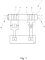
- Fig.1 shows a first embodiment of a measuring device 1, wherein the measuring device is an inductive conductivity measuring device.
- the measuring device has a measuring tube 2, an excitation device 3, a measuring device 4 and a control device 5.
- the excitation device 3 has an excitation coil 6 and an excitation source 7, wherein a first analog-digital converter 8 belongs to the control device 5.
- the measuring device 4 has a measuring coil 9 and an amplifier 10, wherein a second analog-digital converter 11 belongs to the control device 5.
- a medium 12 is in the measuring tube 2, whereby an electrical conductivity as a property of the medium 12 is determined by the measuring device 1.
- the excitation device 3 generates an excitation signal with the excitation source 7 and transmits this to the medium 12 with the excitation coil 6.
- the excitation signal transmitted to the medium 12 generates a measuring signal by induction in the measuring coil 9 of the measuring device 4, which is measured by the measuring device 4 and amplified with the amplifier 10.
- the excitation signal is transmitted from the excitation coil 6 to the measuring coil 9 by eddy currents in the medium 12.
- Both the excitation signal and the amplified measurement signal are fed to the control device 5.
- the control device 5 first determines an amplitude of the supplied excitation signal and an amplitude of the supplied measurement signal. To do this, the control device 5 digitizes the excitation signal with the first analog-digital converter 8 and the measurement signal with the second analog-digital converter 11. The amplification of the measurement signal by the amplifier 10 is set such that an input signal range of the second analog-digital converter 11 is exhausted.
- the control device 5 further determines the amplitude of the excitation signal by executing a lock-in process on the digitized excitation signal and the amplitude of the measurement signal by executing the lock-in process on the digitized measurement signal.
- a Goertzel algorithm is also carried out by the control device 5.
- the conductivity of the medium 12 is then determined using the ratio of the amplitude of the measurement signal to the amplitude of the excitation signal.
- the control device 5 also carries out a SIL2 signal plausibility check using the digitized excitation signal and the digitized measurement signal. In addition, the control device 5 compensates for a medium-independent residual coupling between the excitation coil and the measurement coil before executing the lock-in method.
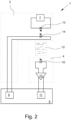
- Fig. 2 shows a second embodiment of a measuring device not according to the invention, which is a first turbidity measuring device.
- the measuring device 1 has an excitation device 3, a measuring device 4 and a control device 5.
- the excitation device 3 has a light source 13, an excitation source 7 and an excitation light sensor 14.
- the measuring device 4 has a light sensor 15 and an amplifier 16.
- the control device 5 has a first analog-digital converter 8 and a second analog-digital converter 11.
- turbidity is determined as a property of a medium 12 by the measuring device 1.
- the excitation device 3 generates an excitation signal with the excitation source 7 and transmits the excitation signal to the medium 12 via the light source 13.
- the excitation signal transmitted to the medium 12 generates a measurement signal in the light sensor 15, which is measured by the measuring device 4 and amplified by the amplifier 10.
- the excitation signal is transmitted from the light source 13 to the light sensor 15 via light in the medium 12.
- the light source 13, the medium 12 and the light sensor 15 are arranged in such a way that the excitation signal generated by the light source 13 and transmitted by the medium 12 hits the light sensor 15 directly.
- the light is scattered in the medium 12 by the components of the medium 12 that make it turbid, so that the light transmitted from the medium 12 to the light sensor 15 is a measure of the turbidity of the medium 12.
- the excitation signal is measured by the excitation device 3 with the excitation light sensor 14.
- Both the measured excitation signal and the amplified measured signal are fed to the control device 5.
- the control device 5 first determines an amplitude of the supplied excitation signal and an amplitude of the supplied measurement signal. To do this, the control device 5 digitizes the excitation signal with the first analog-digital converter 8 and the measurement signal with the second analog-digital converter 11. The amplification of the measurement signal by the amplifier 10 is set such that an input signal range of the second analog-digital converter 11 is exhausted.
- the control device 5 further determines the amplitude of the excitation signal by executing a lock-in process on the digitized excitation signal and the amplitude of the measurement signal by executing the lock-in process on the digitized measurement signal.
- control device 5 When executing the lock-in process, the control device 5 also executes a Goertzel algorithm. The turbidity of the medium 12 is then determined using the ratio of the amplitude of the measurement signal to the amplitude of the excitation signal. Furthermore, the control device 5 carries out a SIL2 signal plausibility check using the digitized excitation signal and the digitized measurement signal.
- Fig.3 shows a third embodiment of a measuring device not according to the invention, which is a second turbidity measuring device.
- the measuring device 1 has an excitation device 3, a measuring device 4 and a control device 5.
- the excitation device 3 has a light source 13, an excitation source 7 and an excitation light sensor 14.
- the measuring device 4 has a light sensor 15 and an amplifier 16.
- the control device 5 has a first analog-digital converter 8 and a second analog-digital converter 11.
- turbidity is determined as a property of a medium 12 by the measuring device 1.
- the excitation device 3 generates an excitation signal with the excitation source 7 and transmits the excitation signal to the medium 12 through the light source 13.
- the excitation signal transmitted to the medium 12 generates a measurement signal in the light sensor 15, which is measured by the measuring device 4 and amplified by the amplifier 10.
- the excitation signal is transmitted from the light source 13 to the light sensor 15 by light in the medium 12.
- the light source 13, the medium 12 and the light sensor 15 are arranged in such a way that the excitation signal generated by the light source 13 indirectly hits the light sensor 15.
- the light is scattered in the medium 12 by the components of the medium 12 that make the medium 12 turbid and The scattered light then hits the light sensor 15, whereby the scattered light is a measure of the turbidity of the medium 12.
- the excitation signal is measured by the excitation device 3 with the excitation light sensor 14.
- Both the measured excitation signal and the amplified measured measurement signal are fed to the control device 5.
- the control device 5 first determines an amplitude of the supplied excitation signal and an amplitude of the supplied measurement signal. To do this, the control device 5 digitizes the excitation signal with the first analog-digital converter 8 and the measurement signal with the second analog-digital converter 11. The amplification of the measurement signal by the amplifier 10 is set such that an input signal range of the second analog-digital converter 11 is exhausted.
- the control device 5 further determines the amplitude of the excitation signal by executing a lock-in process on the digitized excitation signal and the amplitude of the measurement signal by executing the lock-in process on the digitized measurement signal. The turbidity of the medium 12 is then determined using the ratio of the amplitude of the measurement signal to the amplitude of the excitation signal.
Landscapes
- Chemical & Material Sciences (AREA)
- General Health & Medical Sciences (AREA)
- Life Sciences & Earth Sciences (AREA)
- Health & Medical Sciences (AREA)
- Analytical Chemistry (AREA)
- Biochemistry (AREA)
- Physics & Mathematics (AREA)
- General Physics & Mathematics (AREA)
- Immunology (AREA)
- Pathology (AREA)
- Chemical Kinetics & Catalysis (AREA)
- Electrochemistry (AREA)
- Investigating Or Analyzing Materials By The Use Of Magnetic Means (AREA)
- Investigating Or Analysing Materials By Optical Means (AREA)
Description
- Die Erfindung betrifft ein Messgerät zur Bestimmung einer Eigenschaft eines Mediums. Das Messgerät weist eine Anregungseinrichtung, eine Messeinrichtung und eine Steuereinrichtung auf, wobei die Steuereinrichtung zur Steuerung sowohl der Anregungseinrichtung als auch der Messeinrichtung ausgebildet ist. Im Betrieb des Messgeräts erzeugt die Anregungseinrichtung zunächst ein Anregungssignal und überträgt das Anregungssignal auf das Medium. Das auf das Medium übertragene Anregungssignal erzeugt in der Messeinrichtung ein Messsignal, wobei die Messeinrichtung das Messsignal dann misst. Weiter bestimmt die Steuereinrichtung eine Amplitude des Anregungssignals und eine Amplitude des gemessenen Messsignals und bestimmt die Eigenschaft des Mediums unter Verwendung der Amplitude des Anregungssignals und der Amplitude des Messsignals. Aus dem Stand der Technik sind unter anderen induktive Leitfähigkeitsmessgeräte und Trübungsmessgeräte als Messgeräte der beschriebenen Art bekannt.
- Ein solches induktives Leitfähigkeitsmessgerät misst als die Eigenschaft des Mediums eine elektrische Leitfähigkeit des Mediums. Die Anregungseinrichtung eines induktiven Leitfähigkeitsmessgeräts weist für gewöhnlich eine Anregungsspule zur Übertragung des Anregungssignals auf das Medium und die Messeinrichtung eine Messspule zur Messung des Messsignals auf. Die Steuereinrichtung weist z. B. zur Bestimmung der Amplitude des Anregungssignals und der Amplitude des Messsignals jeweils einen analogen Lock-In-Verstärker auf. Im Allgemeinen ist ein Lock-In-Verstärker ein Verstärker zur Messung eines schwachen Wechselsignals. Zur Messung des Wechselsignals moduliert der Lock-In-Verstärker das Wechselsignal mit einem Referenzwechselsignal mit bekannter Referenzfrequenz und wirkt als schmalbandiger Bandpassfilter, was bedeutet, dass Gleichsignale, Wechselsignale mit von der Referenzfrequenz abweichenden Frequenzen und Rauschen im zu messenden Wechselsignal reduziert werden. Auf diese Weise wird das Signal-Rausch-Verhältnis des Wechselsignals verbessert. Ein Lock-In-Verstärker weist für gewöhnlich einen Signaleingang für das zu messende Wechselsignal, eine Referenzsignalquelle zur Erzeugung des Referenzwechselsignals, einen Phasenschieber, einen Mischer und einen Tiefpassfilter auf. Der Phasenschieber bewirkt, dass das mit dem Referenzwechselsignal modulierte Wechselsignal und das Referenzwechselsignal in Phase sind. Der Multiplizierer mischt dann das Wechselsignal und das Referenzwechselsignal miteinander und der Tiefpassfilter filtert das Ergebnis des Mischens. Das tiefpassgefilterte Ergebnis ist proportional zur Amplitude des ummodulierten Wechselsignals.
- Die Anregungseinrichtung eines Trübungsmessgeräts der beschriebenen Art weist für gewöhnlich eine Lichtquelle zur Übertragung des Anregungssignals auf das Medium und die Messeinrichtung einen Lichtsensor zur Messung des Messsignals auf. Auch die Steuereinrichtung eines Trübungsmessgeräts weist zur Bestimmung der Amplitude des Anregungssignals und der Amplitude des Messsignals z. B. jeweils einen analogen Lock-In-Verstärker auf. Insoweit gelten die Ausführungen zum induktiven Leitfähigkeitsmessgerät entsprechend für das Trübungsmessgerät.
- Aufgabe der vorliegenden Erfindung ist die Angabe eines Messgeräts zur Bestimmung einer Eigenschaft eines Mediums, bei denen die Genauigkeit der Bestimmung der Eigenschaft des Mediums verbessert ist.
- Die gegenwärtige Offenbarung beschreibt ein Verfahren zur Bestimmung einer Eigenschaft eines Mediums, bei dem die aufgezeigte Aufgabe gelöst ist. Das Verfahren ist zunächst im Wesentlichen dadurch gekennzeichnet, dass die Amplitude des Anregungssignals bestimmt wird, indem das Anregungssignal digitalisiert und auf das digitalisierte Anregungssignal ein Lock-In-Verfahren angewendet wird. Weiter ist es dadurch gekennzeichnet, dass die Amplitude des Messsignals bestimmt wird, indem das Messsignal digitalisiert und auf das digitalisierte Messsignal das Lock-In-Verfahren angewendet wird.
- Bei aus dem Stand der Technik bekannten Verfahren erfolgen die Bestimmung der Amplitude des Anregungssignals und die Bestimmung der Amplitude des Messsignals durch die Ausführung von Lock-In-Verfahren in der analogen Domäne. Die analoge Domäne ist dadurch gekennzeichnet, dass analoge Signale analog verarbeitet werden. Verarbeiten bedeutet dabei z. B. verstärken, filtern oder mischen. Im Allgemeinen wird bei einem Lock-In-Verfahren, wie auch bei einem Lock-In-Verstärker, zur Messung eines Wechselsignals dieses zunächst mit einem Referenzwechselsignal mit bekannter Referenzfrequenz moduliert. Dann werden das modulierte Wechselsignal und das Referenzwechselsignal in Phase gebracht und anschließend die beiden Signale miteinander gemischt. Schließlich wird das Ergebnis des Mischens tiefpassgefiltert. Das tiefpassgefilterte Ergebnis des Mischens ist proportional zur Amplitude des unmodulierten Wechselsignals. Bei einem digitalen Lock-In-Verfahren werden das Anregungssignal und das Messsignal vor der Ausführung des Lock-In-Verfahrens zunächst digitalisiert und erfolgt das Ausführen des Lock-In-Verfahrens in der digitalen Domäne. Die digitale Domäne ist dadurch gekennzeichnet, dass digitale Signale digital verarbeitet werden. Verarbeiten bedeutet dabei z. B. verstärken, filtern oder mischen. Durch das Ausführen des Lock-In-Verfahrens in der digitalen und nicht in der analogen Domäne wird die Genauigkeit der Bestimmung der Eigenschaft des Mediums im Vergleich zur Ausführung in der analogen Domäne verbessert. Darüber sind die Anforderungen an die die Verfahren ausführenden Einrichtungen reduziert, wodurch auch die Herstellungskosten reduziert sind.
- In einer Ausgestaltung des Verfahrens ist vorgesehen, dass bei Ausführung des digitalen Lock-In-Verfahrens ein Goertzel-Algorithmus ausgeführt wird. Dieser Ausgestaltung liegt die Erkenntnis zugrunde, dass ein Lock-In-Verfahren einem Bandpass entspricht und dieser durch einen Goertzel-Algorithmus und anschließender Tiefpassfilterung ausgeführt werden kann. In einer weiteren Ausgestaltung des Verfahrens ist vorgesehen, dass unter Verwendung des digitalisierten Anregungssignals und des digitalisierten Messsignals eine Signalplausibilisierung durchgeführt wird. Vorzugsweise wird eine SIL2-Signalplausibilisierung durchgeführt. Dabei steh SIL für den Ausdruck Safety Integrity Level, welcher aus der internationalen Normung IEC 61508/IEC61511 bekannt ist.
- Die Erfindung bezieht sich auf ein Messgerät zur Bestimmung einer Eigenschaft eines Mediums, bei dem die aufgezeigte Aufgabe gelöst ist. Das erfindungsgemäße Messgerät ist zunächst und im Wesentlichen dadurch gekennzeichnet, dass die Steuereinrichtung die Amplitude des Anregungssignals durch Digitalisierung des Anregungssignals und Ausführung eines Lock-In-Verfahrens auf das digitalisierte Anregungssignal bestimmt. Weiter ist das Messgerät dadurch gekennzeichnet, dass die Steuereinrichtung der Amplitude des Messsignals durch Digitalisierung des Messsignals und Ausführung des Lock-In-Verfahrens auf das digitalisierte Medium bestimmt. Beides erfolgt im Betrieb des Messgeräts durch die Steuereinrichtung.
- Aus dem Stand der Technik bekannte Messgeräte der vorliegenden Art weisen analoge Lock-In-Verstärker auf. Es ist erkannt worden, dass diese Lock-In-Verstärker aufgrund ihrer analogen Signalverarbeitung Fehler bei der Bestimmung der Eigenschaft des Mediums verursachen und ein erheblicher analoger Schaltungsaufwand notwendig ist, um diese Fehler zu reduzieren. Im Gegensatz dazu erfolgt die Bestimmung der Eigenschaft des Mediums erfindungsgemäß erst nach der Digitalisierung sowohl des Anregungssignals als auch des Messsignals und damit in der digitalen Domäne, wodurch diese Fehler vermieden werden. Somit können die analogen Lock-In-Verstärker entfallen, wodurch die Herstellungskosten reduziert und Genauigkeit der Bestimmung der Eigenschaft des Mediums verbessert werden.
- In einer Ausgestaltung des erfindungsgemäßen Messgeräts ist vorgesehen, dass die Steuereinrichtung zur Ausführung eines der beschriebenen Verfahren ausgebildet ist. Das erfindungsgemäße Messgerät ist ein induktives Leitfähigkeitsmessgerät. Dabei weist die Anregungseinrichtung eine Anregungsspule zur Übertragung des Anregungssignals auf das Medium und die Messeinrichtung eine Messspule zur Messung des Messsignals auf. Das Messgerät bestimmt eine elektrische Leitfähigkeit als die Eigenschaft des Mediums unter Verwendung des Verhältnisses der Amplitude des Messsignals zur Amplitude des Anregungssignals. Das Anregungssignal wird dabei als Wirbelstrom durch das Medium von der Anregungs- zur Messspule übertragen.
- Ein Verhältnis der Amplitude des Messsignals zur Amplitude des Anregungssignals ist ein Maß für die Leitfähigkeit des Mediums. Die Übertragung des Anregungssignals von der Anregungs- zur Messspule erfolgt dabei zum einen durch das Medium und zum anderen durch eine vom Medium unabhängige magnetische Restkopplung zwischen der Mess- und der Anregungsspule. Diese mediumsunabhängige Restkopplung bewirkt einen Fehler bei der Bestimmung der elektrischen Leitfähigkeit des Mediums, weshalb dieser Fehler zu kompensieren ist.
- Aus dem Stand der Technik sind zwei Verfahren zur Kompensation des Fehlers bekannt. Beiden Verfahren gemein ist, dass in einem ersten Verfahrensschritt ein durch die Restkopplung erzeugtes Messsignal bestimmt wird. Das geschieht durch Übertragung des Anregungssignals von der Anregungs- zur Messspule bei Abwesenheit eines Mediums, wodurch gewährleistet ist, dass die Übertragung des Anregungssignals nicht durch das Medium erfolgt. Somit entspricht das auf diese Weise erzeugte Messsignal dem Fehler durch die mediumsunabhängige Restkopplung. Gemäß dem ersten bekannten Verfahren wird das durch die Restkopplung verursachte Messsignal von dem Messsignal subtrahiert, was bei Vorhandensein eines Mediums bestimmt wird. Gemäß dem zweiten bekannten Verfahren wird die Wirkung der Restkopplung über eine Kompensationswicklung mit einem einstellbaren Widerstand kompensiert. Dabei wird der Widerstandswert des einstellbaren Widerstands so lange variiert, bis bei den Messungen mit abwesendem Medium kein Messsignal mehr gemessen wird. Beiden Verfahren ist somit auch gemein, dass die Kompensation nach der jeweiligen Messung und somit nach der Ausführung eines Lock-In-Verfahrens erfolgt. Es ist erkannt worden, dass diese nachträgliche Kompensation zu Fehlern führt. Deshalb ist erfindungsgemäß vorgesehen, dass die Steuereinrichtung eine mediumsunabhängige Restkopplung zwischen der Anregungsspule und der Messspule vor der Ausführung des Lock-In-Verfahrens kompensiert.
- In einer nicht erfindungsgemäßen Ausgestaltung des Messgeräts ist vorgesehen, dass es kein induktives Leitfähigkeitsmessgerät, sondern ein Trübungsmessgerät ist. Bei diesem weist die Anregungseinrichtung eine Lichtquelle zur Übertragung des Anregungssignals auf das Medium und die Messeinrichtung einen Lichtsensor zur Messung des Messsignals auf. Das Messgerät bestimmt eine Trübung als die Eigenschaft des Mediums unter Verwendung des Verhältnisses der Amplitude des Messsignals zur Amplitude des Anregungssignals. Dabei wird das Anregungssignal als von der Lichtquelle erzeugtes Licht über das Medium übertragen.
- In einer Ausgestaltung des Trübungsmessgeräts ist vorgesehen, dass die Anregungseinrichtung einen weiteren Lichtsensor zur Messung des Anregungssignals aufweist.
- In einer weiteren Ausgestaltung des Trübungsmessgeräts ist vorgesehen, dass die Lichtquelle, das Medium und der Lichtsensor derart zueinander angeordnet sind, dass das von der Lichtquelle erzeugte und vom Medium übertragene Anregungssignal direkt auf den Lichtsensor trifft. Dabei wird das Licht im Medium an den das Medium trübenden Bestandteilen des Mediums gestreut, sodass das vom Medium auf den Lichtsensor übertragene Licht ein Maß für die Trübung des Mediums ist.
- In einer zur vorstehenden Ausgestaltung alternativen Ausgestaltung des Trübungsmessgeräts ist vorgesehen, dass die Lichtquelle, das Medium und der Lichtsensor derart angeordnet sind, dass das von der Lichtquelle erzeugte Anregungssignal von dem Medium gestreut wird und das gestreute Anregungssignal auf den Lichtsensor trifft. Dabei wird das Licht im Medium an den das Medium trübenden Bestandteilen des Mediums gestreut, sodass das vom Medium auf den Lichtsensor übertragene gestreute Licht ein Maß für die Trübung des Mediums ist.
- Die Ausführungen zur ersten Lehre gelten entsprechend auch für die zweite Lehre und umgekehrt. Im Einzelnen ist eine Vielzahl von Möglichkeiten gegeben, das erfindungsgemäße Messgerät zur Bestimmung einer Eigenschaft des Mediums auszugestalten und weiterzubilden. Dazu wird verwiesen auf die nachfolgende Beschreibung von bevorzugten Ausführungsbeispielen in Verbindung mit der Zeichnung. In der Zeichnung zeigt schematisch und abstrahiert
- Fig. 1
- ein erstes Ausführungsbeispiel eines Messgeräts zur Bestimmung einer Eigenschaft eines Mediums,
- Fig. 2
- ein zweites Ausführungsbeispiel eines solchen Messgeräts und
- Fig. 3
- ein drittes Ausführungsbeispiel eines solchen Messgeräts.
-
Fig. 1 zeigt ein erstes Ausführungsbeispiel eines Messgeräts 1, wobei es sich bei dem Messgerät um ein induktives Leitfähigkeitsmessgerät handelt. Das Messgerät weist ein Messrohr 2, eine Anregungseinrichtung 3, eine Messeinrichtung 4 und eine Steuereinrichtung 5 auf. Die Anregungseinrichtung 3 weist eine Anregungsspule 6 und eine Anregungsquelle 7 auf, wobei ein erster Analog-Digital-Umsetzer 8 zur Steuereinrichtung 5 gehört. Die Messeinrichtung 4 weist eine Messspule 9 und einen Verstärker 10 auf, wobei ein zweiter Analog-Digital-Umsetzer 11 zur Steuereinrichtung 5 gehört. - Im Betrieb des Messgeräts 1 ist ein Medium 12 im Messrohr 2, wobei eine elektrische Leitfähigkeit als eine Eigenschaft des Mediums 12 durch das Messgerät 1 bestimmt wird. Dazu erzeugt die Anregungseinrichtung 3 mit der Anregungsquelle 7 ein Anregungssignal und überträgt dieses mit der Anregungsspule 6 auf das Medium 12. Das auf das Medium 12 übertragene Anregungssignal erzeugt durch Induktion in der Messspule 9 der Messeinrichtung 4 ein Messsignal, das von der Messeinrichtung 4 gemessen und mit dem Verstärker 10 verstärkt wird. Die Übertragung des Anregungssignals von der Anregungsspule 6 zur Messspule 9 erfolgt dabei durch Wirbelströme im Medium 12.
- Sowohl das Anregungssignal als auch das verstärkte Messsignal sind der Steuereinrichtung 5 zugeführt. Die Steuereinrichtung 5 bestimmt zunächst eine Amplitude des zugeführten Anregungssignals und eine Amplitude des zugeführten Messsignals. Dazu digitalisiert die Steuereinrichtung 5 das Anregungssignal mit dem ersten Analog-Digital-Umsetzer 8 und das Messsignal mit dem zweiten Analog-Digital-Umsetzer 11. Die Verstärkung des Messsignals durch den Verstärker 10 ist ist derart eingestellt, dass ein Eingangssignalbereich des zweiten Analog-Digital-Umsetzers 11 ausgeschöpft wird. Weiter bestimmt die Steuereinrichtung 5 durch Ausführung eines Lock-In-Verfahrens auf das digitalisierte Anregungssignal die Amplitude des Anregungssignals und durch Ausführung des Lock-In-Verfahrens auf das digitalisierte Messsignal die Amplitude des Messsignals. Bei der Ausführung des Lock-In-Verfahrens wird von der Steuereinrichtung 5 auch ein Goertzel-Algorithmus ausgeführt. Unter Verwendung des Verhältnisses der Amplitude des Messsignals zur Amplitude des Anregungssignals wird dann die Leitfähigkeit des Mediums 12 bestimmt.
- Weiter führt die Steuereinrichtung 5 unter Verwendung des digitalisierten Anregungssignals und des digitalisierten Messsignals eine SIL2-Signalplausibilisierung durch. Darüber hinaus kompensiert die Steuereinrichtung 5 eine mediumsunabhängige Restkopplung zwischen der Anregungsspule und der Messspule vor der Ausführung des Lock-In-Verfahrens.
-
Fig. 2 zeigt ein zweites nicht erfindungsgemäßes Ausführungsbeispiel eines Messgeräts, bei dem es sich um ein erstes Trübungsmessgerät handelt. Das Messgerät 1 weist eine Anregungseinrichtung 3, eine Messeinrichtung 4 und eine Steuereinrichtung 5 auf. Die Anregungseinrichtung 3 weist eine Lichtquelle 13, eine Anregungsquelle 7 und einen Anregungslichtsensor 14 auf. Die Messeinrichtung 4 weist einen Lichtsensor 15 und einen Verstärker 16 auf. Die Steuereinrichtung 5 weist einen ersten Analog-Digital-Umsetzer 8 und einen zweiten Analog-Digital-Umsetzer 11 auf. - Im Betrieb des Messgeräts 1 wird eine Trübung als eine Eigenschaft eines Mediums 12 durch das Messgerät 1 bestimmt. Dazu erzeugt die Anregungseinrichtung 3 mit der Anregungsquelle 7 ein Anregungssignal und überträgt das Anregungssignal durch die Lichtquelle 13 auf das Medium 12. Das auf das Medium 12 übertragene Anregungssignal erzeugt in dem Lichtsensor 15 ein Messsignal, das von der Messeinrichtung 4 gemessen und mit dem Verstärker 10 verstärkt wird. Die Übertragung des Anregungssignals von der Lichtquelle 13 zum Lichtsensor 15 erfolgt durch Licht im Medium 12. Dabei sind die Lichtquelle 13, das Medium 12 und der Lichtsensor 15 derart zueinander angeordnet, dass das von der Lichtquelle 13 erzeugte und vom Medium 12 übertragene Anregungssignal direkt auf den Lichtsensor 15 trifft. Das Licht wird im Medium 12 an den das Medium 12 trübenden Bestandteilen des Mediums 12 gestreut, sodass das vom Medium 12 auf den Lichtsensor 15 übertragene Licht ein Maß für die Trübung des Mediums 12 ist. Das Anregungssignal wird von der Anregungseinrichtung 3 mit dem Anregungslichtsensor 14 gemessen.
- Sowohl das gemessene Anregungssignal als auch das verstärkte gemessene Messsignal sind der Steuereinrichtung 5 zugeführt. Die Steuereinrichtung 5 bestimmt zunächst eine Amplitude des zugeführten Anregungssignals und eine Amplitude des zugeführten Messsignals. Dazu digitalisiert die Steuereinrichtung 5 das Anregungssignal mit dem ersten Analog-Digital-Umsetzer 8 und das Messsignal mit dem zweiten Analog-Digital-Umsetzer 11. Die Verstärkung des Messsignals durch den Verstärker 10 ist derart eingestellt, dass ein Eingangssignalbereich des zweiten Analog-Digital-Umsetzers 11 ausgeschöpft wird. Weiter bestimmt die Steuereinrichtung 5 durch Ausführung eines Lock-In-Verfahrens auf das digitalisierte Anregungssignal die Amplitude des Anregungssignals und durch Ausführung des Lock-In-Verfahrens auf das digitalisierte Messsignal die Amplitude des Messsignals. Bei der Ausführung des Lock-In-Verfahrens wird von der Steuereinrichtung 5 auch ein Goertzel-Algorithmus ausgeführt. Unter Verwendung des Verhältnisses der Amplitude des Messsignals zur Amplitude des Anregungssignals wird dann die Trübung des Mediums 12 bestimmt. Weiter führt die Steuereinrichtung 5 unter Verwendung des digitalisierten Anregungssignals und des digitalisierten Messsignals eine SIL2-Signalplausibilisierung durch.
-
Fig. 3 zeigt ein drittes nicht erfindungsgemäßes Ausführungsbeispiel eines Messgeräts, bei dem es sich um ein zweites Trübungsmessgerät handelt. Das Messgerät 1 weist eine Anregungseinrichtung 3, eine Messeinrichtung 4 und eine Steuereinrichtung 5 auf. Die Anregungseinrichtung 3 weist eine Lichtquelle 13, eine Anregungsquelle 7 und einen Anregungslichtsensor 14 auf. Die Messeinrichtung 4 weist einen Lichtsensor 15 und einen Verstärker 16 auf. Die Steuereinrichtung 5 weist einen ersten Analog-Digital-Umsetzer 8 und einen zweiten Analog-Digital-Umsetzer 11 auf. - Im Betrieb des Messgeräts 1 wird eine Trübung als eine Eigenschaft eines Mediums 12 durch das Messgerät 1 bestimmt. Dazu erzeugt die Anregungseinrichtung 3 mit der Anregungsquelle 7 ein Anregungssignal und überträgt das Anregungssignal durch die Lichtquelle 13 auf das Medium 12. Das auf das Medium 12 übertragene Anregungssignal erzeugt in dem Lichtsensor 15 ein Messsignal, das von der Messeinrichtung 4 gemessen und mit dem Verstärker 10 verstärkt wird. Die Übertragung des Anregungssignals von der Lichtquelle 13 zum Lichtsensor 15 erfolgt durch Licht im Medium 12. Dabei sind die Lichtquelle 13, das Medium 12 und der Lichtsensor 15 derart zueinander angeordnet, dass das von der Lichtquelle 13 erzeugte Anregungssignal indirekt auf den Lichtsensor 15 trifft. Das Licht wird dabei im Medium 12 an den das Medium 12 trübenden Bestandteilen des Mediums 12 gestreut und das gestreute Licht trifft dann auf den Lichtsensor 15, wobei das gestreute Licht ein Maß für die Trübung des Mediums 12 ist. Das Anregungssignal wird von der Anregungseinrichtung 3 mit dem Anregungslichtsensor 14 gemessen.
- Sowohl das gemessene Anregungssignal als auch das verstärkte gemessene Messsignal sind der Steuereinrichtung 5 zugeführt. Die Steuereinrichtung 5 bestimmt zunächst eine Amplitude des zugeführten Anregungssignals und eine Amplitude des zugeführten Messsignals. Dazu digitalisiert die Steuereinrichtung 5 das Anregungssignal mit dem ersten Analog-Digital-Umsetzer 8 und das Messsignal mit dem zweiten Analog-Digital-Umsetzer 11. Die Verstärkung des Messsignals durch den Verstärker 10 ist derart eingestellt, dass ein Eingangssignalbereich des zweiten Analog-Digital-Umsetzers 11 ausgeschöpft wird. Weiter bestimmt die Steuereinrichtung 5 durch Ausführung eines Lock-In-Verfahrens auf das digitalisierte Anregungssignal die Amplitude des Anregungssignals und durch Ausführung des Lock-In-Verfahrens auf das digitalisierte Messsignal die Amplitude des Messsignals. Unter Verwendung des Verhältnisses der Amplitude des Messsignals zur Amplitude des Anregungssignals wird dann die Trübung des Mediums 12 bestimmt.
-
- 1
- Messgerät
- 2
- Messrohr
- 3
- Anregungseinrichtung
- 4
- Messeinrichtung
- 5
- Steuereinrichtung
- 6
- Anregungsspule
- 7
- Anregungsquelle
- 8
- Erster Analog-Digital-Umsetzer
- 9
- Messspule
- 10
- Verstärker
- 11
- Zweiter Analog-Digital-Umsetzer
- 12
- Medium
- 13
- Lichtquelle
- 14
- Anregungslichtsensor
- 15
- Lichtsensor
Claims (2)
- Messgerät (1) zur Bestimmung einer Eigenschaft eines Mediums (12) mit einer Anregungseinrichtung (3), einer Messeinrichtung (4) und einer Steuereinrichtung (5),wobei im Betrieb des Messgeräts (1) die Anregungseinrichtung (3) ein Anregungssignal erzeugt und das Anregungssignal auf das Medium (12) überträgt, das auf das Medium (12) übertragene Anregungssignal in der Messeinrichtung (4) ein Messsignal erzeugt und die Messeinrichtung (4) das Messsignal misst, die Steuereinrichtung (5) dazu eingerichtet ist, eine Amplitude des Anregungssignals durch Digitalisierung des Anregungssignals und Ausführung eines Lock-In-Verfahrens auf das digitalisierte Anregungssignal zu bestimmen, eine Amplitude des Messsignals durch Digitalisierung des Messsignals und Ausführung des Lock-In-Verfahrens auf das digitalisierte Messsignal zu bestimmen und die Eigenschaft des Mediums (12) unter Verwendung der Amplitude des Anregungssignals und der Amplitude des Messsignals zu bestimmen,wobei das Messgerät (1) ein induktives Leitfähigkeitsmessgerät ist, die Anregungseinrichtung (3) eine Anregungsspule (6) zur Übertragung des Anregungssignals auf das Medium (12) und die Messeinrichtung (4) eine Messspule (9) zur Messung des Messsignals aufweist und eine elektrische Leitfähigkeit die Eigenschaft des Mediums (12) ist, und wobei die Steuereinrichtung (5) weiter dazu eingerichtet ist, eine mediumsunabhängige Restkopplung zwischen der Anregungsspule (6) und der Messspule (9) vor der Ausführung des Lock-In-Verfahrens zu kompensieren.
- Messgerät (1) nach Anspruch 1, dadurch gekennzeichnet, dass die Steuereinrichtung (5) zur Ausführung eines Verfahrens zur Bestimmung einer Eigenschaft des Mediums (12) mit den folgenden Schritten ausgebildet ist:- Erzeugen eines Anregungssignals und Übertragen auf das Medium (12),- Erzeugen eines Messsignal von dem auf das Medium (12) übertragenen Anregungssignal und Messen des Messsignals,- Bestimmen einer Amplitude des Anregungssignals, indem das Anregungssignal digitalisiert und auf das digitalisierte Anregungssignal ein Lock-In-Verfahren angewendet wird,- Bestimmen einer Amplitude des Messsignals, indem das Messsignal digitalisiert und auf das digitalisierte Messsignal das Lock-In-Verfahren angewendet wird,- Bestimmen der Eigenschaft des Mediums (12) unter Verwendung der Amplitude des Anregungssignals und der Amplitude des Messsignals und- Durchführen einer Signalplausibilisierung unter Verwendung des digitalisierten Anregungssignals und des digitalisierten Messsignals.
Applications Claiming Priority (1)
| Application Number | Priority Date | Filing Date | Title |
|---|---|---|---|
| DE102016120785.3A DE102016120785A1 (de) | 2016-11-01 | 2016-11-01 | Verfahren und Messgerät zur Bestimmung einer Eigenschaft eines Mediums |
Publications (2)
| Publication Number | Publication Date |
|---|---|
| EP3315954A1 EP3315954A1 (de) | 2018-05-02 |
| EP3315954B1 true EP3315954B1 (de) | 2024-07-31 |
Family
ID=60119953
Family Applications (1)
| Application Number | Title | Priority Date | Filing Date |
|---|---|---|---|
| EP17196829.0A Active EP3315954B1 (de) | 2016-11-01 | 2017-10-17 | Messgerät zur bestimmung einer eigenschaft eines mediums |
Country Status (4)
| Country | Link |
|---|---|
| US (1) | US10161867B2 (de) |
| EP (1) | EP3315954B1 (de) |
| CN (1) | CN108007970B (de) |
| DE (1) | DE102016120785A1 (de) |
Citations (1)
| Publication number | Priority date | Publication date | Assignee | Title |
|---|---|---|---|---|
| DE102010029762A1 (de) * | 2010-06-07 | 2011-12-08 | Endress + Hauser Conducta Gesellschaft für Mess- und Regeltechnik mbH + Co. KG | Verfahren zur Bestimmung einer Restkopplung eines induktiven Leitfähigkeitssensors |
Family Cites Families (24)
| Publication number | Priority date | Publication date | Assignee | Title |
|---|---|---|---|---|
| US5140168A (en) * | 1990-12-03 | 1992-08-18 | Great Lakes Instruments, Inc. | Turbidimeter signal processing circuit using alternating light sources |
| US5331177A (en) * | 1993-04-26 | 1994-07-19 | Honeywell Inc. | Turbidity sensor with analog to digital conversion capability |
| DE19837828C1 (de) * | 1998-08-20 | 2000-04-06 | Forschungszentrum Juelich Gmbh | Verfahren und Vorrichtung zur oberflächennahen Detektion von Stromdichteverteilungen in einem Untergrund |
| US6586939B1 (en) * | 1999-12-24 | 2003-07-01 | Baker Hughes Incorporated | Method and apparatus for reducing the effects of parasitic and galvanic currents in a resistivity measuring tool |
| JP4112882B2 (ja) * | 2001-07-19 | 2008-07-02 | 株式会社日立メディコ | 生体光計測装置 |
| GB2389176C (en) * | 2002-05-27 | 2011-07-27 | Kidde Ip Holdings Ltd | Smoke detector |
| US6833973B2 (en) * | 2002-06-27 | 2004-12-21 | International Business Machines Corporation | Apparatus and method to calibrate a servo sensor |
| DE60310712T2 (de) * | 2003-08-28 | 2007-10-11 | Siemens Ag | Verfahren und System zur Wellenlängenmodulationsspektrometrie |
| DE102006043809A1 (de) * | 2006-09-13 | 2008-03-27 | Endress + Hauser Gmbh + Co. Kg | Vorrichtung zur Bestimmung und/oder Überwachung einer Prozessgröße |
| EP1912058B1 (de) * | 2006-10-14 | 2010-12-15 | Roche Diagnostics GmbH | Anordnung und Verfahren zum Erfassen und Auswerten optischer Signale |
| DE102008018592A1 (de) * | 2008-04-11 | 2009-10-15 | Endress + Hauser Conducta Gesellschaft für Mess- und Regeltechnik mbH + Co. KG | Verfahren und Vorrichtung zur Trübungsmessung |
| WO2009143635A1 (en) * | 2008-05-27 | 2009-12-03 | Flavio Heer | Apparatus for lock-in amplifying an input signal and method for generating a reference signal for a lock-in amplifier |
| DE102009037706A1 (de) * | 2009-08-17 | 2011-02-24 | Opsolution Nanophotonics Gmbh | Verfahren und Vorrichtung zur Bestimmung der Konzentration von NO2 in Gasgemischen |
| US8532197B2 (en) * | 2010-02-16 | 2013-09-10 | The Aerospace Corporation | Methods and systems for detecting temporally oscillating sources in video signals using a recursive infinite impulse response (IIR) filter technique |
| CN101915869A (zh) * | 2010-08-13 | 2010-12-15 | 天津大学 | 减小激励信号幅值波动引入测量误差的方法及实施装置 |
| DE102010064248A1 (de) * | 2010-12-28 | 2012-06-28 | Endress + Hauser Conducta Gesellschaft für Mess- und Regeltechnik mbH + Co. KG | Verfahren zur Bestimmung einer Messgröße eines Mediums, insbesondere zur Trübungsmessung |
| AU2012222178B2 (en) * | 2011-02-24 | 2014-12-18 | Gen-Probe Incorporated | Systems and methods for distinguishing optical signals of different modulation frequencies in an optical signal detector |
| CN102801395A (zh) * | 2011-05-23 | 2012-11-28 | 天津港东科技发展股份有限公司 | 数字锁相放大实验装置 |
| US8914242B2 (en) * | 2011-07-21 | 2014-12-16 | Thermo Ramsey, Inc. | Signal processing in guided wave cutoff spectroscopy |
| KR101958504B1 (ko) * | 2011-09-09 | 2019-03-14 | 콘티넨탈 테베스 아게 운트 코. 오하게 | 차동 변압기 변위 센서에서의 괴르첼 알고리즘에 의한 진폭 평가 |
| DE102011084784A1 (de) * | 2011-10-19 | 2013-04-25 | Robert Bosch Gmbh | Verfahren zur Plausibilisierung von Sensorsignalen sowie Verfahren und Vorrichtung zur Ausgabe eines Auslösesignals |
| CN102495380B (zh) * | 2011-12-13 | 2013-07-10 | 华北电力大学 | 一种数字信号锁定型空间磁场检测系统 |
| CN102539519A (zh) * | 2012-01-06 | 2012-07-04 | 南昌航空大学 | Acfm数字化检测仪 |
| JP6281677B2 (ja) * | 2013-03-08 | 2018-02-21 | 国立大学法人名古屋大学 | 磁気計測装置 |
-
2016
- 2016-11-01 DE DE102016120785.3A patent/DE102016120785A1/de not_active Withdrawn
-
2017
- 2017-10-17 EP EP17196829.0A patent/EP3315954B1/de active Active
- 2017-11-01 US US15/800,228 patent/US10161867B2/en active Active
- 2017-11-01 CN CN201711055899.7A patent/CN108007970B/zh not_active Expired - Fee Related
Patent Citations (1)
| Publication number | Priority date | Publication date | Assignee | Title |
|---|---|---|---|---|
| DE102010029762A1 (de) * | 2010-06-07 | 2011-12-08 | Endress + Hauser Conducta Gesellschaft für Mess- und Regeltechnik mbH + Co. KG | Verfahren zur Bestimmung einer Restkopplung eines induktiven Leitfähigkeitssensors |
Non-Patent Citations (1)
| Title |
|---|
| MARCUS WOLFF: "Photoacoustic Signal Processing: Lock-In Amplification vs. Goertzel Algorithm", 18TH INTERNATIONAL CONFERENCE ON PHOTOACOUSTIC AND PHOTOTHERMAL PHENOMENA, 1 January 2015 (2015-01-01), XP055685867 * |
Also Published As
| Publication number | Publication date |
|---|---|
| US10161867B2 (en) | 2018-12-25 |
| CN108007970B (zh) | 2022-07-12 |
| EP3315954A1 (de) | 2018-05-02 |
| CN108007970A (zh) | 2018-05-08 |
| US20180120226A1 (en) | 2018-05-03 |
| DE102016120785A1 (de) | 2018-05-03 |
Similar Documents
| Publication | Publication Date | Title |
|---|---|---|
| EP1217337B1 (de) | Verfahren zur Prüfung des Messbetriebes eines Flüssigkeitmessgerätes | |
| DE102015109009B4 (de) | Stromsensorchip mit Magnetfeldsensor | |
| DE69804857T2 (de) | Integritätsprüfung von elektroden | |
| DE69425160T2 (de) | Vorrichtung zur messung von materialeigenschaft | |
| DE102011078334A1 (de) | Verfahren und System zum Kalibrieren eines Shunt-Widerstands | |
| EP2651036A1 (de) | Induktiver Näherungssensor | |
| DE112011101945T5 (de) | Robustes kapazitives Messsystern | |
| EP2568262B1 (de) | Verfahren zum Betrieb mehrerer benachtbarter magnetisch-induktiver Durchflussmessgeräte und Anordnung mehrerer benachtbarter magnetisch-induktiver Durchflussmessgeräte | |
| EP3215811B1 (de) | Bestimmung einer position eines beweglichen elementes eines für ein kraftfahrzeug bestimmten linearaktuators | |
| DE102008033198B4 (de) | Verfahren und Vorrichtung zum Verstärken eines Signals sowie diese verwendendes Prüfgerät | |
| EP1377887B1 (de) | Schaltungsanordnung und verfahren zur temperaturkompensation | |
| DE102016122914B4 (de) | Vorrichtung und Verfahren zum Bereitstellen eines Erregungsstroms an einem elektromagnetischen Flusssensor | |
| EP2703828B1 (de) | Vorrichtung zur Reduzierung von Störeinflüssen bei der Mantelfehlerortung | |
| EP3074726A1 (de) | Induktiver messtaster und verfahren zum betreiben eines induktiven messtasters | |
| EP4428500B1 (de) | Verfahren zum betreiben eines magnetisch-induktiven durchflussmessgeräts und magnetisch-induktives durchflussmessgerät | |
| EP3315954A1 (de) | Verfahren und messgerät zur bestimmung einer eigenschaft eines mediums | |
| DE102013005037A1 (de) | Schaltungsanordnung und Verfahren zum Kompensieren einer Widerstandsdrift in Wirbelstromsensoren | |
| EP3327431A1 (de) | Induktives leitfähigkeitsmessgerät und verfahren zum betreiben eines induktiven leitfähigkeitsmessgeräts | |
| EP4071447B1 (de) | Verfahren zum bestimmen der leitfähigkeit eines mediums, betriebsverfahren eines magnetisch-induktiven durchflussmessgeräts, und magnetisch-induktives durchflussmessgerät | |
| DE10334517B4 (de) | Messgerät für elektrische Energie für ein Wechselstromnetz | |
| EP3118592A1 (de) | Verfahren zum betreiben eines coriolis-massedurchflussmessgeräts und diesbezügliches coriolis-massedurchflussmessgerät | |
| EP1311804B1 (de) | Schaltungsanordnung und verfahren zur ansteuerung und signalauswertung von sensoren | |
| DE69123827T2 (de) | Gerät zur zerstörungsfreien Prüfung mit Wirbelströmen | |
| DE102019120666B3 (de) | Sensorvorrichtung zur breitbandigen Messung von elektrischen Strömen durch einen Leiter und Verfahren zur breitbandigen Messung | |
| EP0137896B1 (de) | Schaltungsanordnung zur Kompensation von Schwankungen des Uebertragungsfaktors eines linearen Magnetfeldsensors |
Legal Events
| Date | Code | Title | Description |
|---|---|---|---|
| PUAI | Public reference made under article 153(3) epc to a published international application that has entered the european phase |
Free format text: ORIGINAL CODE: 0009012 |
|
| STAA | Information on the status of an ep patent application or granted ep patent |
Free format text: STATUS: THE APPLICATION HAS BEEN PUBLISHED |
|
| AK | Designated contracting states |
Kind code of ref document: A1 Designated state(s): AL AT BE BG CH CY CZ DE DK EE ES FI FR GB GR HR HU IE IS IT LI LT LU LV MC MK MT NL NO PL PT RO RS SE SI SK SM TR |
|
| AX | Request for extension of the european patent |
Extension state: BA ME |
|
| STAA | Information on the status of an ep patent application or granted ep patent |
Free format text: STATUS: REQUEST FOR EXAMINATION WAS MADE |
|
| 17P | Request for examination filed |
Effective date: 20181102 |
|
| RBV | Designated contracting states (corrected) |
Designated state(s): AL AT BE BG CH CY CZ DE DK EE ES FI FR GB GR HR HU IE IS IT LI LT LU LV MC MK MT NL NO PL PT RO RS SE SI SK SM TR |
|
| STAA | Information on the status of an ep patent application or granted ep patent |
Free format text: STATUS: EXAMINATION IS IN PROGRESS |
|
| 17Q | First examination report despatched |
Effective date: 20200422 |
|
| GRAP | Despatch of communication of intention to grant a patent |
Free format text: ORIGINAL CODE: EPIDOSNIGR1 |
|
| STAA | Information on the status of an ep patent application or granted ep patent |
Free format text: STATUS: GRANT OF PATENT IS INTENDED |
|
| INTG | Intention to grant announced |
Effective date: 20240314 |
|
| RAP3 | Party data changed (applicant data changed or rights of an application transferred) |
Owner name: KROHNE MESSTECHNIK GMBH |
|
| GRAS | Grant fee paid |
Free format text: ORIGINAL CODE: EPIDOSNIGR3 |
|
| GRAA | (expected) grant |
Free format text: ORIGINAL CODE: 0009210 |
|
| STAA | Information on the status of an ep patent application or granted ep patent |
Free format text: STATUS: THE PATENT HAS BEEN GRANTED |
|
| AK | Designated contracting states |
Kind code of ref document: B1 Designated state(s): AL AT BE BG CH CY CZ DE DK EE ES FI FR GB GR HR HU IE IS IT LI LT LU LV MC MK MT NL NO PL PT RO RS SE SI SK SM TR |
|
| REG | Reference to a national code |
Ref country code: CH Ref legal event code: EP Ref country code: GB Ref legal event code: FG4D Free format text: NOT ENGLISH |
|
| REG | Reference to a national code |
Ref country code: DE Ref legal event code: R096 Ref document number: 502017016301 Country of ref document: DE |
|
| REG | Reference to a national code |
Ref country code: IE Ref legal event code: FG4D Free format text: LANGUAGE OF EP DOCUMENT: GERMAN |
|
| P01 | Opt-out of the competence of the unified patent court (upc) registered |
Free format text: CASE NUMBER: APP_44016/2024 Effective date: 20240729 |
|
| REG | Reference to a national code |
Ref country code: LT Ref legal event code: MG9D |
|
| REG | Reference to a national code |
Ref country code: NL Ref legal event code: MP Effective date: 20240731 |
|
| PG25 | Lapsed in a contracting state [announced via postgrant information from national office to epo] |
Ref country code: PT Free format text: LAPSE BECAUSE OF FAILURE TO SUBMIT A TRANSLATION OF THE DESCRIPTION OR TO PAY THE FEE WITHIN THE PRESCRIBED TIME-LIMIT Effective date: 20241202 |
|
| PG25 | Lapsed in a contracting state [announced via postgrant information from national office to epo] |
Ref country code: PT Free format text: LAPSE BECAUSE OF FAILURE TO SUBMIT A TRANSLATION OF THE DESCRIPTION OR TO PAY THE FEE WITHIN THE PRESCRIBED TIME-LIMIT Effective date: 20241202 |
|
| PGFP | Annual fee paid to national office [announced via postgrant information from national office to epo] |
Ref country code: DE Payment date: 20241218 Year of fee payment: 8 |
|
| PG25 | Lapsed in a contracting state [announced via postgrant information from national office to epo] |
Ref country code: NO Free format text: LAPSE BECAUSE OF FAILURE TO SUBMIT A TRANSLATION OF THE DESCRIPTION OR TO PAY THE FEE WITHIN THE PRESCRIBED TIME-LIMIT Effective date: 20241031 |
|
| PG25 | Lapsed in a contracting state [announced via postgrant information from national office to epo] |
Ref country code: PL Free format text: LAPSE BECAUSE OF FAILURE TO SUBMIT A TRANSLATION OF THE DESCRIPTION OR TO PAY THE FEE WITHIN THE PRESCRIBED TIME-LIMIT Effective date: 20240731 Ref country code: FI Free format text: LAPSE BECAUSE OF FAILURE TO SUBMIT A TRANSLATION OF THE DESCRIPTION OR TO PAY THE FEE WITHIN THE PRESCRIBED TIME-LIMIT Effective date: 20240731 Ref country code: NL Free format text: LAPSE BECAUSE OF FAILURE TO SUBMIT A TRANSLATION OF THE DESCRIPTION OR TO PAY THE FEE WITHIN THE PRESCRIBED TIME-LIMIT Effective date: 20240731 Ref country code: GR Free format text: LAPSE BECAUSE OF FAILURE TO SUBMIT A TRANSLATION OF THE DESCRIPTION OR TO PAY THE FEE WITHIN THE PRESCRIBED TIME-LIMIT Effective date: 20241101 |
|
| PG25 | Lapsed in a contracting state [announced via postgrant information from national office to epo] |
Ref country code: BG Free format text: LAPSE BECAUSE OF FAILURE TO SUBMIT A TRANSLATION OF THE DESCRIPTION OR TO PAY THE FEE WITHIN THE PRESCRIBED TIME-LIMIT Effective date: 20240731 |
|
| PG25 | Lapsed in a contracting state [announced via postgrant information from national office to epo] |
Ref country code: LV Free format text: LAPSE BECAUSE OF FAILURE TO SUBMIT A TRANSLATION OF THE DESCRIPTION OR TO PAY THE FEE WITHIN THE PRESCRIBED TIME-LIMIT Effective date: 20240731 |
|
| PG25 | Lapsed in a contracting state [announced via postgrant information from national office to epo] |
Ref country code: IS Free format text: LAPSE BECAUSE OF FAILURE TO SUBMIT A TRANSLATION OF THE DESCRIPTION OR TO PAY THE FEE WITHIN THE PRESCRIBED TIME-LIMIT Effective date: 20241130 |
|
| PG25 | Lapsed in a contracting state [announced via postgrant information from national office to epo] |
Ref country code: HR Free format text: LAPSE BECAUSE OF FAILURE TO SUBMIT A TRANSLATION OF THE DESCRIPTION OR TO PAY THE FEE WITHIN THE PRESCRIBED TIME-LIMIT Effective date: 20240731 |
|
| PG25 | Lapsed in a contracting state [announced via postgrant information from national office to epo] |
Ref country code: ES Free format text: LAPSE BECAUSE OF FAILURE TO SUBMIT A TRANSLATION OF THE DESCRIPTION OR TO PAY THE FEE WITHIN THE PRESCRIBED TIME-LIMIT Effective date: 20240731 Ref country code: RS Free format text: LAPSE BECAUSE OF FAILURE TO SUBMIT A TRANSLATION OF THE DESCRIPTION OR TO PAY THE FEE WITHIN THE PRESCRIBED TIME-LIMIT Effective date: 20241031 |
|
| PG25 | Lapsed in a contracting state [announced via postgrant information from national office to epo] |
Ref country code: RS Free format text: LAPSE BECAUSE OF FAILURE TO SUBMIT A TRANSLATION OF THE DESCRIPTION OR TO PAY THE FEE WITHIN THE PRESCRIBED TIME-LIMIT Effective date: 20241031 Ref country code: PL Free format text: LAPSE BECAUSE OF FAILURE TO SUBMIT A TRANSLATION OF THE DESCRIPTION OR TO PAY THE FEE WITHIN THE PRESCRIBED TIME-LIMIT Effective date: 20240731 Ref country code: NO Free format text: LAPSE BECAUSE OF FAILURE TO SUBMIT A TRANSLATION OF THE DESCRIPTION OR TO PAY THE FEE WITHIN THE PRESCRIBED TIME-LIMIT Effective date: 20241031 Ref country code: NL Free format text: LAPSE BECAUSE OF FAILURE TO SUBMIT A TRANSLATION OF THE DESCRIPTION OR TO PAY THE FEE WITHIN THE PRESCRIBED TIME-LIMIT Effective date: 20240731 Ref country code: LV Free format text: LAPSE BECAUSE OF FAILURE TO SUBMIT A TRANSLATION OF THE DESCRIPTION OR TO PAY THE FEE WITHIN THE PRESCRIBED TIME-LIMIT Effective date: 20240731 Ref country code: IS Free format text: LAPSE BECAUSE OF FAILURE TO SUBMIT A TRANSLATION OF THE DESCRIPTION OR TO PAY THE FEE WITHIN THE PRESCRIBED TIME-LIMIT Effective date: 20241130 Ref country code: HR Free format text: LAPSE BECAUSE OF FAILURE TO SUBMIT A TRANSLATION OF THE DESCRIPTION OR TO PAY THE FEE WITHIN THE PRESCRIBED TIME-LIMIT Effective date: 20240731 Ref country code: GR Free format text: LAPSE BECAUSE OF FAILURE TO SUBMIT A TRANSLATION OF THE DESCRIPTION OR TO PAY THE FEE WITHIN THE PRESCRIBED TIME-LIMIT Effective date: 20241101 Ref country code: FI Free format text: LAPSE BECAUSE OF FAILURE TO SUBMIT A TRANSLATION OF THE DESCRIPTION OR TO PAY THE FEE WITHIN THE PRESCRIBED TIME-LIMIT Effective date: 20240731 Ref country code: ES Free format text: LAPSE BECAUSE OF FAILURE TO SUBMIT A TRANSLATION OF THE DESCRIPTION OR TO PAY THE FEE WITHIN THE PRESCRIBED TIME-LIMIT Effective date: 20240731 Ref country code: BG Free format text: LAPSE BECAUSE OF FAILURE TO SUBMIT A TRANSLATION OF THE DESCRIPTION OR TO PAY THE FEE WITHIN THE PRESCRIBED TIME-LIMIT Effective date: 20240731 |
|
| PG25 | Lapsed in a contracting state [announced via postgrant information from national office to epo] |
Ref country code: SM Free format text: LAPSE BECAUSE OF FAILURE TO SUBMIT A TRANSLATION OF THE DESCRIPTION OR TO PAY THE FEE WITHIN THE PRESCRIBED TIME-LIMIT Effective date: 20240731 Ref country code: RO Free format text: LAPSE BECAUSE OF FAILURE TO SUBMIT A TRANSLATION OF THE DESCRIPTION OR TO PAY THE FEE WITHIN THE PRESCRIBED TIME-LIMIT Effective date: 20240731 Ref country code: DK Free format text: LAPSE BECAUSE OF FAILURE TO SUBMIT A TRANSLATION OF THE DESCRIPTION OR TO PAY THE FEE WITHIN THE PRESCRIBED TIME-LIMIT Effective date: 20240731 |
|
| PG25 | Lapsed in a contracting state [announced via postgrant information from national office to epo] |
Ref country code: EE Free format text: LAPSE BECAUSE OF FAILURE TO SUBMIT A TRANSLATION OF THE DESCRIPTION OR TO PAY THE FEE WITHIN THE PRESCRIBED TIME-LIMIT Effective date: 20240731 |
|
| PG25 | Lapsed in a contracting state [announced via postgrant information from national office to epo] |
Ref country code: CZ Free format text: LAPSE BECAUSE OF FAILURE TO SUBMIT A TRANSLATION OF THE DESCRIPTION OR TO PAY THE FEE WITHIN THE PRESCRIBED TIME-LIMIT Effective date: 20240731 |
|
| PG25 | Lapsed in a contracting state [announced via postgrant information from national office to epo] |
Ref country code: SK Free format text: LAPSE BECAUSE OF FAILURE TO SUBMIT A TRANSLATION OF THE DESCRIPTION OR TO PAY THE FEE WITHIN THE PRESCRIBED TIME-LIMIT Effective date: 20240731 Ref country code: IT Free format text: LAPSE BECAUSE OF FAILURE TO SUBMIT A TRANSLATION OF THE DESCRIPTION OR TO PAY THE FEE WITHIN THE PRESCRIBED TIME-LIMIT Effective date: 20240731 |
|
| REG | Reference to a national code |
Ref country code: DE Ref legal event code: R097 Ref document number: 502017016301 Country of ref document: DE |
|
| REG | Reference to a national code |
Ref country code: CH Ref legal event code: PL |
|
| PLBE | No opposition filed within time limit |
Free format text: ORIGINAL CODE: 0009261 |
|
| STAA | Information on the status of an ep patent application or granted ep patent |
Free format text: STATUS: NO OPPOSITION FILED WITHIN TIME LIMIT |
|
| GBPC | Gb: european patent ceased through non-payment of renewal fee |
Effective date: 20241031 |
|
| PG25 | Lapsed in a contracting state [announced via postgrant information from national office to epo] |
Ref country code: MC Free format text: LAPSE BECAUSE OF FAILURE TO SUBMIT A TRANSLATION OF THE DESCRIPTION OR TO PAY THE FEE WITHIN THE PRESCRIBED TIME-LIMIT Effective date: 20240731 |
|
| 26N | No opposition filed |
Effective date: 20250501 |
|
| PG25 | Lapsed in a contracting state [announced via postgrant information from national office to epo] |
Ref country code: GB Free format text: LAPSE BECAUSE OF NON-PAYMENT OF DUE FEES Effective date: 20241031 |
|
| PG25 | Lapsed in a contracting state [announced via postgrant information from national office to epo] |
Ref country code: BE Free format text: LAPSE BECAUSE OF NON-PAYMENT OF DUE FEES Effective date: 20241031 Ref country code: LU Free format text: LAPSE BECAUSE OF NON-PAYMENT OF DUE FEES Effective date: 20241017 |
|
| PG25 | Lapsed in a contracting state [announced via postgrant information from national office to epo] |
Ref country code: FR Free format text: LAPSE BECAUSE OF NON-PAYMENT OF DUE FEES Effective date: 20241031 |
|
| PG25 | Lapsed in a contracting state [announced via postgrant information from national office to epo] |
Ref country code: CH Free format text: LAPSE BECAUSE OF NON-PAYMENT OF DUE FEES Effective date: 20241031 |
|
| REG | Reference to a national code |
Ref country code: BE Ref legal event code: MM Effective date: 20241031 |
|
| PG25 | Lapsed in a contracting state [announced via postgrant information from national office to epo] |
Ref country code: SE Free format text: LAPSE BECAUSE OF FAILURE TO SUBMIT A TRANSLATION OF THE DESCRIPTION OR TO PAY THE FEE WITHIN THE PRESCRIBED TIME-LIMIT Effective date: 20240731 |
|
| PG25 | Lapsed in a contracting state [announced via postgrant information from national office to epo] |
Ref country code: IE Free format text: LAPSE BECAUSE OF NON-PAYMENT OF DUE FEES Effective date: 20241017 |
|
| REG | Reference to a national code |
Ref country code: AT Ref legal event code: MM01 Ref document number: 1708918 Country of ref document: AT Kind code of ref document: T Effective date: 20241017 |
|
| PG25 | Lapsed in a contracting state [announced via postgrant information from national office to epo] |
Ref country code: AT Free format text: LAPSE BECAUSE OF NON-PAYMENT OF DUE FEES Effective date: 20241017 |
|
| PG25 | Lapsed in a contracting state [announced via postgrant information from national office to epo] |
Ref country code: CY Free format text: LAPSE BECAUSE OF FAILURE TO SUBMIT A TRANSLATION OF THE DESCRIPTION OR TO PAY THE FEE WITHIN THE PRESCRIBED TIME-LIMIT; INVALID AB INITIO Effective date: 20171017 |
|
| PG25 | Lapsed in a contracting state [announced via postgrant information from national office to epo] |
Ref country code: HU Free format text: LAPSE BECAUSE OF FAILURE TO SUBMIT A TRANSLATION OF THE DESCRIPTION OR TO PAY THE FEE WITHIN THE PRESCRIBED TIME-LIMIT; INVALID AB INITIO Effective date: 20171017 |