EP3315934A1 - Magnetostrictive sensor, magnetic structure and production method thereof, motor drive unit provided with magnetostrictive sensor, and motor assisted bicycle - Google Patents
Magnetostrictive sensor, magnetic structure and production method thereof, motor drive unit provided with magnetostrictive sensor, and motor assisted bicycle Download PDFInfo
- Publication number
- EP3315934A1 EP3315934A1 EP16814457.4A EP16814457A EP3315934A1 EP 3315934 A1 EP3315934 A1 EP 3315934A1 EP 16814457 A EP16814457 A EP 16814457A EP 3315934 A1 EP3315934 A1 EP 3315934A1
- Authority
- EP
- European Patent Office
- Prior art keywords
- magnetostrictive
- lines
- cross
- base material
- section
- Prior art date
- Legal status (The legal status is an assumption and is not a legal conclusion. Google has not performed a legal analysis and makes no representation as to the accuracy of the status listed.)
- Granted
Links
Images








Classifications
-
- G—PHYSICS
- G01—MEASURING; TESTING
- G01L—MEASURING FORCE, STRESS, TORQUE, WORK, MECHANICAL POWER, MECHANICAL EFFICIENCY, OR FLUID PRESSURE
- G01L3/00—Measuring torque, work, mechanical power, or mechanical efficiency, in general
- G01L3/02—Rotary-transmission dynamometers
- G01L3/04—Rotary-transmission dynamometers wherein the torque-transmitting element comprises a torsionally-flexible shaft
- G01L3/10—Rotary-transmission dynamometers wherein the torque-transmitting element comprises a torsionally-flexible shaft involving electric or magnetic means for indicating
- G01L3/101—Rotary-transmission dynamometers wherein the torque-transmitting element comprises a torsionally-flexible shaft involving electric or magnetic means for indicating involving magnetic or electromagnetic means
- G01L3/102—Rotary-transmission dynamometers wherein the torque-transmitting element comprises a torsionally-flexible shaft involving electric or magnetic means for indicating involving magnetic or electromagnetic means involving magnetostrictive means
-
- B—PERFORMING OPERATIONS; TRANSPORTING
- B62—LAND VEHICLES FOR TRAVELLING OTHERWISE THAN ON RAILS
- B62M—RIDER PROPULSION OF WHEELED VEHICLES OR SLEDGES; POWERED PROPULSION OF SLEDGES OR SINGLE-TRACK CYCLES; TRANSMISSIONS SPECIALLY ADAPTED FOR SUCH VEHICLES
- B62M6/00—Rider propulsion of wheeled vehicles with additional source of power, e.g. combustion engine or electric motor
- B62M6/40—Rider propelled cycles with auxiliary electric motor
- B62M6/45—Control or actuating devices therefor
- B62M6/50—Control or actuating devices therefor characterised by detectors or sensors, or arrangement thereof
-
- G—PHYSICS
- G01—MEASURING; TESTING
- G01L—MEASURING FORCE, STRESS, TORQUE, WORK, MECHANICAL POWER, MECHANICAL EFFICIENCY, OR FLUID PRESSURE
- G01L3/00—Measuring torque, work, mechanical power, or mechanical efficiency, in general
- G01L3/02—Rotary-transmission dynamometers
- G01L3/04—Rotary-transmission dynamometers wherein the torque-transmitting element comprises a torsionally-flexible shaft
- G01L3/10—Rotary-transmission dynamometers wherein the torque-transmitting element comprises a torsionally-flexible shaft involving electric or magnetic means for indicating
- G01L3/101—Rotary-transmission dynamometers wherein the torque-transmitting element comprises a torsionally-flexible shaft involving electric or magnetic means for indicating involving magnetic or electromagnetic means
- G01L3/102—Rotary-transmission dynamometers wherein the torque-transmitting element comprises a torsionally-flexible shaft involving electric or magnetic means for indicating involving magnetic or electromagnetic means involving magnetostrictive means
- G01L3/103—Details about the magnetic material used
-
- G—PHYSICS
- G01—MEASURING; TESTING
- G01L—MEASURING FORCE, STRESS, TORQUE, WORK, MECHANICAL POWER, MECHANICAL EFFICIENCY, OR FLUID PRESSURE
- G01L3/00—Measuring torque, work, mechanical power, or mechanical efficiency, in general
- G01L3/02—Rotary-transmission dynamometers
- G01L3/04—Rotary-transmission dynamometers wherein the torque-transmitting element comprises a torsionally-flexible shaft
- G01L3/10—Rotary-transmission dynamometers wherein the torque-transmitting element comprises a torsionally-flexible shaft involving electric or magnetic means for indicating
- G01L3/101—Rotary-transmission dynamometers wherein the torque-transmitting element comprises a torsionally-flexible shaft involving electric or magnetic means for indicating involving magnetic or electromagnetic means
- G01L3/105—Rotary-transmission dynamometers wherein the torque-transmitting element comprises a torsionally-flexible shaft involving electric or magnetic means for indicating involving magnetic or electromagnetic means involving inductive means
-
- H—ELECTRICITY
- H10—SEMICONDUCTOR DEVICES; ELECTRIC SOLID-STATE DEVICES NOT OTHERWISE PROVIDED FOR
- H10N—ELECTRIC SOLID-STATE DEVICES NOT OTHERWISE PROVIDED FOR
- H10N35/00—Magnetostrictive devices
- H10N35/101—Magnetostrictive devices with mechanical input and electrical output, e.g. generators, sensors
Definitions
- the present invention relates to a magnetostrictive sensor, a magnetic structure, a method for fabricating the magnetic structure, a motor-driven unit including the magnetostrictive sensor, and an electric motor-assisted bicycle including the magnetostrictive sensor.
- the above-described structure of the magnetostrictive sensor causes a magnetic permeability of the magnetostrictive material of the magnetostrictive portion to change when a force acts on the base material on which the magnetostrictive portion is formed. Accordingly, the impedance of the coil disposed to surround the magnetostrictive portion changes. The magnetostrictive sensor detects the change in the impedance of the coil, thereby detecting a torque or a load.
- Sensitivity of such a magnetostrictive sensor is affected by a magnetostriction constant and a magnetic permeability of a magnetostrictive material.
- the magnetostriction constant and the magnetic permeability of the magnetostrictive material vary depending on a chemical composition of the magnetostrictive material.
- a Fe-Ni alloy shows significant changes of the magnetostriction constant and the magnetic permeability depending on the Ni content in the alloy.
- a Fe-Co alloy shows significant changes of the magnetostriction constant and the magnetic permeability depending on the Co content in the alloy.
- the chemical composition of the magnetostrictive material for use in a magnetostrictive sensor is adjusted to increase sensitivity of the magnetostrictive sensor.
- the chemical composition of the magnetostrictive material is adjusted in such a manner that the magnetostriction constant and the magnetic permeability have values suitable for increasing sensitivity of the magnetostrictive sensor.
- Patent Document 1 discloses a magnetostrictive torque sensor including a magnetostrictive film made of a Ni-Fe alloy.
- the chemical composition of the Ni-Fe alloy is adjusted in such a manner that the product of the magnetostriction constant and the magnetic permeability is 90% or more of the maximum value thereof.
- Patent Document 1 Japanese Patent Application Publication No. 2007-93244
- inventors of the present invention conducted various studies to achieve both an increase in sensitivity of a magnetostrictive sensor and facilitation of manufacturing of the magnetostrictive sensor at the same time.
- the chemical composition of the magnetostrictive material constituting the magnetostrictive portion was investigated in detail again. Consequently, it was found that a stress occurs inside the magnetostrictive portion when the magnetostrictive portion includes portions having different chemical compositions of the magnetostrictive material. More specifically, it was found that in a magnetostrictive portion made of a magnetostrictive material including a plurality of elements, the presence of portions having different concentrations of one of the elements causes a stress inside the magnetostrictive portion.
- sensor sensitivity can be increased without strict control of the chemical composition of the magnetostrictive material in forming the magnetostrictive portion. Specifically, it was found that sensor sensitivity can be sufficiently increased even if the chemical composition of the magnetostrictive material deviates to some degree from a target chemical composition (e.g., chemical composition theoretically determined in order to increase the sensor sensitivity). That is, the inventors found that generation of a stress inside the magnetostrictive portion can achieve both an increase in sensitivity of the magnetostrictive sensor and facilitation of manufacturing of the magnetostrictive sensor at the same time.
- a target chemical composition e.g., chemical composition theoretically determined in order to increase the sensor sensitivity
- a magnetostrictive sensor includes a magnetic structure including a columnar base material extending along an axis and a magnetostrictive portion disposed on an outer peripheral surface of the base material and containing a plurality of elements.
- the magnetostrictive portion includes a plurality of portions having different concentrations of at least one of the plurality of elements.
- the magnetostrictive portion satisfies at least one of requirements (A), (B), and (C):
- a magnetostrictive sensor according to an embodiment of the present invention can have increased sensitivity and can be manufactured efficiently.
- FIG. 1 is a partial cross-sectional view schematically illustrating a configuration of a magnetostrictive sensor according to an embodiment of the present invention.
- the following description is directed to a magnetostrictive torque sensor (hereinafter referred to simply as a "torque sensor" in some cases) 1 for detecting a torque acting on a base material 21 attached to an unillustrated rotating shaft, as an example of a magnetostrictive sensor.
- FIG. 1 schematically illustrates a configuration of the torque sensor 1 for description.
- the torque sensor 1 includes a magnetic structure 20 including a magnetostrictive film 2 (magnetostrictive portion) and a detection unit 30 including coils 3 and 4.
- the magnetic structure 20 is formed in a cylindrical shape extending along an axis A.
- the magnetic structure 20 is disposed on an outer peripheral surface of an unillustrated rotating shaft.
- FIG. 2 schematically illustrates a configuration of the magnetic structure 20.
- the magnetic structure 20 includes a cylindrical base material 21 extending along the axis A (i.e., extending axially) and the magnetostrictive film 2.
- the configuration of the magnetic structure 20 will be described in detail later.
- the magnetostrictive film 2 is disposed on an outer peripheral surface 21s of the cylindrical base material 21.
- the magnetostrictive film 2 includes a plurality of magnetostrictive lines 2a whose configuration will be described in detail later.
- FIG. 3 illustrates the magnetostrictive film 2 of the magnetic structure 20 seen in a direction orthogonal to the axis A (see FIG. 1 ).
- the pattern of the magnetostrictive film 2 illustrated in FIG. 3 is an example.
- the plurality of magnetostrictive lines 2a extend in directions intersecting the axis A when viewed in the direction orthogonal to the axis A.
- an interspace between adjacent ones of the magnetostrictive lines 2a is expressed as an interspace I.
- the detection unit 30 includes the two cylindrical coils 3 and 4 and a yoke 5. As illustrated in FIG. 1 , the coils 3 and 4 are disposed to surround the magnetic structure 20. In the example of FIG. 1 , the coils 3 and 4 are disposed side by side in the axial direction with respect to the magnetic structure 20. Specifically, as illustrated in FIG. 1 , the coils 3 and 4 are disposed with respect to the magnetic structure 20 in such a manner that the coil 3 surrounds one region 2b of the magnetostrictive film 2 and the coil 4 surrounds the other region 2c of the magnetostrictive film 2.
- the yoke 5 has a recess in which the coils 3 and 4 are disposed. The coils 3 and 4 are disposed inside the tubular yoke 5.
- the coils 3 and 4 are connected to an alternating current (AC) power supply 6 as illustrated in FIG. 11 to thereby generate an AC magnetic field around the coils 3 and 4.
- the coils 3 and 4, the yoke 5, and the base material 21 constitute a magnetic circuit.
- the coils 3 and 4 are also connected to a torque detection circuit 7.
- FIG. 11 illustrates an example of a configuration of an electronic circuit included in the torque sensor 1.
- the circuit configuration illustrated in FIG. 11 is widely known as the electronic circuit included in the torque sensor 1.
- the circuit illustrated in FIG. 11 includes the AC power supply 6 and the torque detection circuit 7.
- the AC power supply 6 applies an AC voltage to the coils 3 and 4.
- the torque detection circuit 7 detects a voltage generated in the coils 3 and 4 to thereby detect a torque generated in the base material 21.
- the torque detection circuit 7 obtains a voltage difference Vout between the coils 3 and 4 and then, based on the difference V out , obtains the torque generated in the base material 21 by using an unillustrated arithmetic circuit.
- the electronic circuit included in the torque sensor 1 is not limited to the configuration illustrated in FIG. 11 .
- the length L/width W of the magnetostrictive lines 2a of the magnetostrictive film 2 illustrated in FIG. 3 satisfies, for example, Expression (2) below.
- the magnetostrictive lines 2a extend in a first direction intersecting the axis A in the region 2b of the magnetostrictive film 2 when viewed in the direction orthogonal to the axis A.
- the magnetostrictive lines 2a extend in a second direction intersecting the first direction in the region 2c of the magnetostrictive film 2 when viewed in the direction orthogonal to the axis A. That is, the magnetostrictive lines 2a have bending portions Z each bending at an angle ⁇ , in a center portion of the magnetostrictive film 2 in the axial direction of the base material 21.
- the magnetostrictive film 2 is formed to have a coverage percentage defined in Equation (1) of 30% or more and 95% or less.
- the length L/width W of the magnetostrictive lines 2a is the sum of the length/width of the magnetostrictive lines 2a in the first portions 2m and the length/width of the magnetostrictive lines 2a in the second portions 2n.
- the length/width of each magnetostrictive line 2a in the first portion 2m can be obtained by (length L 1 of magnetostrictive line 2a from end X to bending portion Z illustrated in FIG. 3 )/(width of magnetostrictive line 2a in first portion 2m).
- each magnetostrictive line 2a in the second portion 2n can be obtained by (length L 2 of magnetostrictive line 2a from bending portion Z to end Y illustrated in FIG. 3 )/(width of magnetostrictive line 2a in second portion 2n).
- the torque sensor 1 having high sensitivity can be obtained. That is, in Equation (1), if the coverage percentage is 30% or more, sufficient sensitivity of the torque sensor 1 can be obtained. If the coverage percentage is 95% or less, the shape of the magnetostrictive film 2 does not vary easily. Accordingly, if the coverage percentage is 95% or less, adjacent ones of the magnetostrictive lines 2a do not contact each other, and thus, sufficient sensitivity of the torque sensor 1 can be obtained.
- the coverage percentage is preferably 50% or more.
- the coverage percentage is more preferably 60% or more.
- the coverage percentage is preferably 93% or less.
- the coverage percentage is more preferably 90% or less.
- the coverage percentage is much more preferably 85% or less.
- the magnetostrictive film 2 illustrated in FIG. 3 further includes connecting parts 26 each connecting ends of adjacent ones of the magnetostrictive lines 2a in the axial direction.
- the connecting parts 26 are disposed at both axial ends of the magnetostrictive lines 2a. Since the connecting parts 26 connecting the plurality of magnetostrictive lines 2a are provided in the magnetostrictive film 2, the plurality of magnetostrictive lines 2a are not easily separated from the base material 21. Thus, strength of magnetostrictive film 2 can be enhanced.
- FIG. 4 schematically illustrates a cross section of the magnetic structure 20 illustrated in FIG. 1 .
- the cross section illustrated in FIG. 4 is obtained by cutting the magnetic structure 20 in a plane orthogonal to the extension direction of the magnetostrictive lines 2a. More specifically, the cross section illustrated in FIG. 4 is a cross section in a case where the magnetostrictive lines 2a are cut in a plane perpendicular to the first direction (i.e., direction from the end X of the magnetostrictive film 2 to the bending portions Z in FIG. 2 ), that is, a cross section taken along line C-C in FIG. 3 in a direction perpendicularly to the drawing sheet.
- the magnetic structure 20 includes the cylindrical base material 21 and the magnetostrictive film 2 disposed on the outer peripheral surface 21s of the base material 21.
- "M" corresponds to "W” in FIG. 3 .
- the total content of metals except Fe is more preferably 77 mass% or less.
- the total content of metals except Fe is much more preferably 74 mass% or less.
- the metals except Fe preferably include at least one selected from the group consisting essentially of Ni, Co, and Cr.
- the Ni content (concentration) is preferably 60 mass% or more and 80 mass% or less.
- the Ni content is more preferably 64 mass% or more.
- the Ni content is much more preferably 67 mass% or more.
- the Ni content is more preferably 77 mass% or less.
- the Ni content is much more preferably 74 mass% or less.
- the S content (concentration) of the magnetostrictive film 2 is preferably 0.03 mass% or more and 0.12 mass% or less.
- the S content is more preferably 0.04 mass% or more and 0.10 mass% or less.
- the S content is much more preferably 0.05 mass% or more and 0.09 mass% or less.
- the preferable concentration and more preferable concentration of each element described above refer to concentrations of the element in a center portion m c of each magnetostrictive line 2a (see FIG. 4 ).
- the center portion m c is a center portion of each magnetostrictive line 2a in the thickness direction and the width direction.
- the maximum thickness H of the magnetostrictive film 2 (the distance from the surface of the magnetostrictive film 2 contacting the base material 21, i.e., the outer peripheral surface 21s of the base material 21, to the tip of projection of the magnetostrictive film 2 outward in the radial direction of the base material 21) is, for example, 20 ⁇ m or more and 200 ⁇ m or less.
- the maximum thickness H is preferably 40 ⁇ m or more.
- the maximum thickness H is more preferably 60 ⁇ m or more.
- the maximum thickness H is preferably 140 ⁇ m or less.
- the maximum thickness H is more preferably 100 ⁇ m or less.
- the magnetostrictive lines 2a of the magnetostrictive film 2 when the magnetostrictive lines 2a of the magnetostrictive film 2 is viewed in a cross section taken orthogonally to the extension direction of the magnetostrictive lines 2a, the magnetostrictive lines 2a have portions outside in the radial direction of the base material 21 that are longer than portions of the magnetostrictive lines 2a near the base material 21, in the direction orthogonal to the radial direction of the base material 21 (direction parallel to the outer peripheral surface 21s of the base material 21). Specifically, the magnetostrictive lines 2a have projections 2e individually projecting from bodies of the magnetostrictive lines 2a on the base material 21 in opposite directions orthogonal to the radial direction of the base material 21.
- the presence of the projections 2e of the magnetostrictive lines 2a increases the surface area of the magnetostrictive lines 2a.
- the presence of the projections 2e of the magnetostrictive lines 2a can also reduce the amount of change in output of the torque sensor 1 with respect to a change in concentration of each element in the magnetostrictive film 2.
- An angle ⁇ e formed by the interface between the magnetostrictive lines 2a and the base material 21 and the projecting direction of the projections 2e is preferably an acute angle (less than 90°).
- the angle ⁇ e is more preferably greater than 0° and less than or equal to 45°.
- the angle ⁇ e is much more preferably 30° or less.
- the width M at a predetermined distance from the outer peripheral surface 21s of the base material 21 in the radial direction of the base material 21 is larger than a width N of a contact area 2f between the magnetostrictive film 2 and the outer peripheral surface 21s of the base material 21.
- the plurality of magnetostrictive lines 2a of the magnetostrictive film 2 has the length of a longest portion (length M at the predetermined distance described above, which will be hereinafter referred to as a maximum width M) that is larger than the length N of the contact area 2f between the magnetostrictive film 2 and the outer peripheral surface 21s of the base material 21, in the direction orthogonal to the radial direction of the base material 21.
- the maximum width M is larger than the length of the interspace d between adjacent magnetostrictive lines 2a.
- the interspace d between adjacent magnetostrictive lines 2a refers to an interspace from the contact area 2f between the magnetostrictive line 2a and the base material 21 to the contact area 2f between its adjacent magnetostrictive line 2a and the base material 21.
- the magnetostrictive lines 2a having the shape described above can enhance sensitivity of the torque sensor 1. That is, when the magnetostrictive lines 2a are viewed in the cross section taken orthogonally to the extension direction of the magnetostrictive lines 2a, the maximum width M of the magnetostrictive lines 2a in the magnetostrictive film 2 is larger than the length of the interspace d between adjacent magnetostrictive lines 2a. In such a configuration, the interspace d between the magnetostrictive lines 2a is relatively narrow.
- sensitivity of the torque sensor 1 can be enhanced without changes in the coverage percentage defined in Equation (1) and the value of length L/width W defined in Expression (2).
- the length of the interspace d from the contact area 2f between one magnetostrictive line 2a and the outer peripheral surface 21s of the base material 21 to the contact area 2f between its adjacent magnetostrictive line 2a and the outer peripheral surface 21s of the base material 21 is larger than the sum of the length of the projection 2e of one magnetostrictive line 2a projecting toward its adjacent magnetostrictive line 2a and the length of the projection 2e of the adjacent magnetostrictive line 2a projecting toward the magnetostrictive line 2a.
- the magnetostrictive lines 2a When viewed in the cross section illustrated in FIG. 4 , the magnetostrictive lines 2a has a maximum width M larger than the height (maximum thickness) H of the magnetostrictive lines 2a in the thickness direction. In this manner, the magnetostrictive lines 2a are formed in a flat shape that is longer in the direction (direction parallel to the outer peripheral surface 21s of the base material 21) orthogonal to the radial direction of the base material 21 than in the thickness direction. Accordingly, the surface area of the magnetostrictive lines 2a can be further increased. Thus, a change in magnetic permeability upon application of a force to the magnetostrictive film 2 can be more easily detected.
- the ratio H 1 /H between the maximum thickness H of the magnetostrictive line 2a and the height of ends me of the magnetostrictive line 2a is less than one.
- the Hi/H is preferably 0.8 or less.
- the H 1 /H is more preferably 0.5 or less.
- the Hi/H is much more preferably 0.3 or less.
- the Hi/H is preferably 0.015 or more.
- the magnetostrictive lines 2a are formed in such a manner that the ratio H 1 /H is within the ranges described above so that the surface area of the magnetostrictive lines 2a can be further increased. Thus, a change in magnetic permeability upon application of a force to the magnetostrictive film 2 can be more easily detected.
- Hi/H at 0.5 or less, that is, by setting a half height of the maximum thickness H of the magnetostrictive lines 2a at a position higher than or equal to the maximum width M from the outer peripheral surface 21s of the base material 21, a portion having a width larger than that of the contact area 2f between the magnetostrictive line 2a and the outer peripheral surface 21s of the base material 21 can be provided in a wide range in the thickness direction of the magnetostrictive line 2a. Accordingly, the surface area of the magnetostrictive lines 2a can be further increased. Thus, a change in magnetic permeability upon application of a force to the magnetostrictive films 2 can be more easily detected.
- the magnetostrictive film 2 has portions having different concentrations of at least one of a plurality of elements. This will be specifically described with reference to the drawings.
- FIGS. 5 and 6 illustrate cross sections taken along line D-D in FIG. 2 (cross sections orthogonal to the axis A of the magnetic structure 20: hereinafter also referred to as a first cross section).
- FIGS. 5 and 6 illustrate one of the magnetostrictive lines 2a and its peripheral portion in the D-D cross section of FIG. 2 in an enlarged manner.
- the magnetostrictive line 2a is divided into a plurality of portions 22a, 22b, and 22c that are arranged in a clockwise direction (i.e., direction indicated by an arrow CW in FIG. 5 ) about the axis A (see FIG. 1 ), for example.
- the concentration of at least one of a plurality of elements differs between the portion 22a and the portion 22b and also differs between the portion 22b and the portion 22c. That is, in this embodiment, in the first cross section of the magnetic structure 20, portions having different concentrations of the at least one element are arranged clockwise about the axis A.
- the concentration of the at least one element may be highest in the portion 22a, highest in the portion 22b, or highest in the portion 22c.
- the concentration of the at least one element may change in the clockwise direction in each of the portions 22a, 22b, and 22c.
- the clockwise direction is a circumferential direction of the base material 21.
- the difference between the concentration of the at least one element at the center of the magnetostrictive line 2a and the concentration of the at least one element at the end of the magnetostrictive line 2a is preferably 1 mass% or more, and more preferably 2 mass% or more.
- the concentration difference is, for example, a value less than or equal to the concentration of the at least one element at the center of the magnetostrictive line 2a.
- the concentration of the at least one element may be the same in two of the plurality of portions 22a, 22b, and 22c.
- the concentration of the at least one element may change to be symmetric in the magnetostrictive line 2a with respect to the center line of the magnetostrictive line 2a in the lateral direction.
- each element in the magnetostrictive film 2 is not limited to those of the examples described with reference to FIG. 5 .
- the concentration of at least one of a plurality of elements may differ between the portion 22d and the portion 22e and differ between the portion 22e and the portion 22f. That is, in the first cross section, portions having different concentrations of the at least one element may be arranged in the thickness direction of the magnetostrictive film 2.
- a portion having the highest concentration of the at least one element may be any one of the plurality of portions 22d, 22e, and 22f.
- the concentration of the at least one element may be the same in two of the plurality of portions 22d, 22e, and 22f.
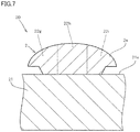
- FIG. 7 illustrates a cross section taken along line E-E in FIG. 2 (cross section orthogonal to the first cross section and passing through the axis A, which will be hereinafter referred to as a second cross section).
- FIG. 7 illustrates one of the magnetostrictive lines 2a and its peripheral portion in the E-E cross section of FIG. 2 in an enlarged manner.
- the concentration of at least one of a plurality of elements may differ between the portion 22g and the portion 22h and differ between the portion 22h and the portion 22i.
- a portion having the highest concentration of the at least one element may be any one of the plurality of portions 22g, 22h, and 22i.
- the concentration of the at least one element may be the same in two of the plurality of portions 22g, 22h, and 22i.
- FIG. 6 shows the case where the three portions having different concentrations of at least one element are arranged in the thickness direction in the magnetostrictive line 2a.
- two or four or more portions having different concentrations of at least one element may be arranged in the thickness direction.
- the expression "portions having different concentrations of an element are arranged in the thickness direction of the magnetostrictive portion” refers to a situation where portions having different concentrations of an element are present in the thickness direction.
- the configuration in which "portions having different concentrations of an element are arranged in the thickness direction of the magnetostrictive portion” includes not only a configuration in which the element concentration changes stepwise in the thickness direction but also a configuration in which the element concentration changes continuously in the thickness direction.
- FIG. 7 shows the case where the three portions having different concentrations of at least one element are arranged along the axis A (see FIG. 1 ) in the magnetostrictive line 2a.
- two or four or more portions having different concentrations of at least one element may be arranged along the axis A.
- the expression "portions having different concentrations of an element are arranged along the axis" refers to a situation where portions having different concentrations of an element are present in the axis direction.
- the configuration in which "portions having different concentrations of an element are arranged along the axis" includes not only a configuration in which the element concentration changes stepwise in the axis direction but also a configuration in which the element concentration changes continuously in the axis direction.
- a plurality of portions 22j, 22k, 221, 22m, 22n, and 22o having different concentrations of at least one element may be arranged in a staggered pattern.
- a plurality of portions having different concentrations of at least one element may be arranged in a staggered pattern.
- FIG. 9 illustrates a simplified cross section taken along line D-D in FIG. 2 (first cross section).
- portions having different concentrations of at least one element may be arranged in each of the magnetostrictive lines 2a disposed in separated regions 50a, 50b, 50c, and 50d in the magnetostrictive film 2.
- the concentration of each of a plurality of elements may be uniform.
- a region where portions having different concentration of at least one element are arranged preferably occupies 1/2 or more of the area of the entire magnetostrictive film 2.
- a region where portions having different concentrations of at least one element may not extend across the entire region of the magnetostrictive film 2.
- portions having different concentrations of at least one element may be arranged in each of the magnetostrictive lines 2a disposed in a plurality of separated regions in the magnetostrictive film 2. In this case, in the magnetostrictive lines 2a in regions except those plurality of separated regions, the concentration of each of a plurality of elements may be uniform.
- the at least one element is preferably an element forming a ferromagnet, for example. In this case, sensitivity of the torque sensor 1 can be increased.
- the magnetostrictive film 2 is formed in the following manner, for example. First, unevenness is formed on an outer peripheral surface 21s of the base material 21. Specifically, as illustrated in FIG. 10 described later, a resist layer 91 is formed on the outer peripheral surface 21s, for example. Thereafter, a magnetostrictive film 2 is formed by plating on the outer peripheral surface 21s of the base material 21 on which the resist layer 91 is provided.
- the magnetostrictive film 2 in which portions having different concentrations of at least one element are arranged in the thickness direction of the magnetostrictive film 2 can be obtained by, for example, changing conditions for forming the magnetostrictive film 2 with time.
- the magnetostrictive film 2 in which portions having different concentrations of at least one element are arranged along the axis A can be obtained by, for example, changing conditions for forming the magnetostrictive film 2 in the axis direction of the base material 21.
- the magnetostrictive lines 2a have the projections 2e, in the cross section illustrated in FIG. 4 , the width M at a predetermined distance from the outer peripheral surface 21s of the base material 21 in the radial direction of the base material 21 (thickness direction of the magnetostrictive line 2a) is larger than a width N of a contact area 2f between the magnetostrictive film 2 and the outer peripheral surface 21s of the base material 21.
- the shape of the magnetostrictive lines 2a described above causes the concentration of the at least one element to be easily changed in the clockwise direction in the magnetostrictive line 2a.
- the concentration of the at least one element can be easily changed without a change in the contact area between the magnetostrictive film 2 and the outer peripheral surface 21s of the base material 21.
- the reason why the presence of the projections 2e in the magnetostrictive lines 2a facilitates a change in concentration of at least one element in the clockwise direction in the magnetostrictive lines 2a will be described later.
- the base material 21 is made of a material different from that of the magnetostrictive film 2, for example, a material having a magnetic permeability lower than that of the magnetostrictive film 2.
- the base material 21 is preferably made of a magnetic material, and is more preferably made of a magnetic material such as Fe, Ni, Co, or Cr.
- the base material 21 may contain a metal such as Al, Ti, Ge, Mo, Ag, or Cu and/or a nonmetal material such as Si, B, S, C, O, or N.
- the magnetic structure 20 may further include a resist layer formed on the surface of the magnetostrictive film 2.
- the resist layer preferably has a thickness of 45 ⁇ m or less.
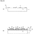
- FIGS. 10(a) and 10(b) are views for describing a method for fabricating a magnetic structure 20.
- FIG. 10 is a cross-sectional view taken along the same plane as that in FIG. 4 , and illustrates the base material 21, the magnetostrictive film 2, the resist layer 91, and so forth in the process of fabricating the magnetic structure 20.
- the method for fabricating a magnetic structure 20 includes the step of forming a resist layer 91 having a predetermined pattern on an outer peripheral surface 21s of a base material 21 and the step of forming a magnetostrictive film 2 on the outer peripheral surface 21s of the base material 21 on which the resist layer 91 is disposed.
- the method for fabricating the magnetic structure 20 will now be specifically described.
- the resist layer 91 having a predetermined pattern is formed on the outer peripheral surface 21s of the base material 21.
- This resist layer 91 is used for forming magnetostrictive lines 2a illustrated in FIGS. 1 through 8 .
- the resist layer 91 can be formed by, for example, a known method such as water transfer or screen printing.
- the thickness of the resist layer 91 is, for example, 3 ⁇ m or more and 45 ⁇ m or less.
- an angle ⁇ f formed by the outer peripheral surface 21s of the base material 21 and an end of the resist layer 91 is preferably an obtuse angle (exceeding 90°).
- a magnetostrictive film 2 is formed on the surface of the base material 21 on which the resist layer 91 is provided.
- the magnetostrictive film 2 is formed in such a manner that a height H of the magnetostrictive film 2 exceeds a height H 1 of the resist layer 91.
- the form of the magnetostrictive film 2 may employ a known method such as sputtering, CVD, or plating.
- a heat treatment is preferably performed at a predetermined temperature (e.g., 300°C or more and 1000°C or less) for a predetermined time (e.g., one minute or more and 48 hours or less).
- a predetermined temperature e.g. 300°C or more and 1000°C or less
- a predetermined time e.g., one minute or more and 48 hours or less.
- plating is performed in such a manner that the projections 2e are formed as described above so that the concentration of at least one element can be easily changed in the clockwise direction in the magnetostrictive lines 2a.
- concentration of an element can be easily changed will be briefly described as follows.
- the composition rate among alloy elements constituting a plating film changes in accordance with a current density in plating.
- the current density can vary in the plating object. For example, in a case where an uneven portion and a corner are formed on the outer surface of the plating object, the current density is higher in projecting portions and corners than in recessed portions.
- plating is performed to form the projections 2e.
- the current density in portions to be projection 2e increases, in a manner similar to those in the projecting portions and corners.
- the current density in the plating is intentionally set at a large value (e.g., 20 A/dm 2 ).
- the current density in portions to be projections 2e can be sufficiently higher than those in the other portions.
- the composition ratio of alloy elements can be made different between the projections 2e and the other portions. That is, in this embodiment, the presence of the projections 2e in the magnetostrictive lines 2a facilitates a change in the concentration of at least one element in the clockwise direction in the magnetostrictive lines 2a.
- An electric motor-assisted bicycle (e.g., a bicycle, a tricycle, or a four-wheel vehicle) according to an embodiment of the present invention includes the torque sensor 1 according to the embodiment described above.
- the torque sensor 1 detects a torque generated when an occupant pedals.
- driving of an electric motor is controlled.
- FIG. 12 schematically illustrates a configuration of the electric motor-assisted bicycle 10 as an example of an electrically assisted vehicle according to the present invention.
- left and right, front and rear, and top and bottom are based on a state in which an occupant 71 sits on a saddle 34 of the electric motor-assisted bicycle 10, facing the handle bar 77 thereof.
- a steering shaft 76 for changing the travelling direction of the vehicle is disposed along the head pipe 14.
- the steering shaft 76 is rotatable in the head pipe 14.
- the handle bar 77 is attached to the upper end of the steering shaft 76.
- a pair of left and right front forks 80 is attached to the lower end of the steering shaft 76.
- a front wheel 82 is attached to the lower end of the front forks 80.
- the front wheel 82 is rotatable about the center axis of the front wheel 82 supported by the front forks 80.
- the saddle 34 is disposed at the upper end of the seat pipe 70.
- a carrier 36 is fixed to the seat pipe 70 and extends rearward therefrom.
- FIG. 13 schematically illustrates a configuration of the motor-driven unit 38 of the electric motor-assisted bicycle 10.
- the motor-driven unit 38 includes the torque sensor 1 according to the embodiment described above. More specifically, as illustrated in FIG. 13 , the motor-driven unit 38 includes a crank shaft 40, a driving sprocket 42, a crank angle sensor 44, the torque sensor 1, an electric motor 48, and a controller 50.
- the motor-driven unit 38 may be configured to be attachable to a bicycle that is not an electric motor-assisted bicycle or may be configured to be interchangeable with an existing motor-driven unit of an electric motor-assisted bicycle.
- crank angle sensor 44 and the torque sensor 1 are disposed near the crank shaft 40.
- the crank angle sensor 44 detects a crank angle ⁇ c that is a rotation angle of the crank shaft 40 rotating by operation of the pedal 54.
- the torque sensor 1 detects a crank torque ⁇ that is a torque applied to the crank shaft 40.
- the electric motor 48 generates an auxiliary driving force to be applied to the driving sprocket 42.
- the controller 50 includes a CPU 64 and a memory 66.
- the CPU 64 performs a necessary computation and controls operations of the electric motor 48 and the electric motor-assisted bicycle 10.
- the memory 66 as a storage unit is constituted by, for example, an EEPROM, and stores programs and data for controlling an operation of the electric motor-assisted bicycle 10, computation data, and so forth.
- the memory 66 stores an assist pattern.
- the CPU 64 of the controller 50 receives the crank angle ⁇ c output from the crank angle sensor 44 and the crank torque ⁇ output from the torque sensor 1. These data items are stored in the memory 66.
- the magnetostrictive film (magnetostrictive portion) 2 satisfies at least one of requirements (a), (b), and (c) described later.
- a stress can be generated inside the magnetostrictive film 2. Consequently, sensitivity of the torque sensor 1 can be sufficiently increased even if the chemical composition of a material constituting the magnetostrictive film 2 deviates to some degree from a target chemical composition. That is, it is possible to achieve both an increase in sensitivity of the torque sensor 1 and facilitation of manufacturing of the torque sensor 1. Thus, the torque sensor 1 having high sensitivity can be efficiently manufactured.
- the magnetostrictive film 2 may satisfy two or more of conditions (a), (b), and (c) described above. In this case, a stress can also be generated inside the magnetostrictive film 2. Thus, the torque sensor 1 having high sensitivity can be efficiently manufactured.
- the torque sensor 1 includes the tubular base material 21 extending along the axis A and the magnetostrictive film 2 formed on the outer peripheral surface 21s of the base material 21.
- the magnetostrictive film 2 includes the plurality of magnetostrictive lines 2a each extending linearly.
- the length M of a longest portion of one of the magnetostrictive lines 2a is larger than the length N of a contact area 2f between the one of the magnetostrictive lines 2a and the outer peripheral surface 21s of the base material 21, and is larger than the length of the interspace d between the contact area 2f and another contact area 2f, in a direction parallel to the outer peripheral surface 21s of the base material 21.
- the another contact area 2f is between one of the magnetostrictive lines 2a adjacent to the one of the magnetostrictive lines 2a and the outer peripheral surface 21s of the base material 21 (i.e., the interspace d between adjacent ones of the magnetostrictive lines 2a).
- the length M of the longest portion is made larger than the length N of the contact area 2f between each magnetostrictive line 2a and the outer peripheral surface 21s of the base material 21 so that the surface area of the magnetostrictive lines 2a can be increased.
- a change in magnetic permeability upon application of a force to the magnetostrictive film 2 can be easily detected.
- sensitivity of the torque sensor 1 can be enhanced under dimensional constraints on the magnetostrictive film 2.
- the length M of the longest portion is larger than the maximum thickness H of the magnetostrictive lines 2a.
- each of the magnetostrictive lines 2a is formed in a flat shape that is longer in the direction parallel to the outer peripheral surface 21s of the base material 21 than in the thickness direction of the magnetostrictive line 2a. Accordingly, the surface area of the magnetostrictive lines 2a can be further increased. Thus, a change in magnetic permeability upon application of a force to the magnetostrictive film 2 can be more easily detected. As a result, sensitivity of the torque sensor 1 can be further enhanced under dimensional constraints on the magnetostrictive film 2.
- the maximum thickness H of each of the magnetostrictive lines 2a is larger than the height H 1 in the thickness direction from the outer peripheral surface 21s of the base material 21 to the longest portion of the base material 21.
- a half of the maximum thickness M of the magnetostrictive lines 2a is greater than or equal to the height H 1 in the thickness direction from the outer peripheral surface 21s of the base material 21 to the longest portion of the base material 21.
- the length of the interspace d from the contact area 2f of one of the magnetostrictive lines 2a and the contact area 2f between one of the magnetostrictive lines 2a adjacent to the one of the magnetostrictive lines 2a and the outer peripheral surface 21s of the base material 21 is larger than the sum of the length of the longest portion projecting from the contact area 2f toward the adjacent magnetostrictive line 2a and the length of the longest portion of the adjacent magnetostrictive line 2a from the contact area 2f between the adjacent magnetostrictive line 2a and the base material 21 toward the one of the magnetostrictive lines 2a, in the direction parallel to the outer peripheral surface 21s of the base material 21.
- the magnetostrictive film 2 includes the connecting parts 26 connecting the plurality of magnetostrictive lines 2a. With this configuration, the magnetostrictive lines 2a are not easily separated from the base material 21. Thus, strength of the magnetostrictive film 2 can be enhanced.
- the torque sensor 1 further includes the coils 3 and 4 disposed to surround the magnetostrictive film 2. Accordingly, a change in magnetic permeability occurring in the magnetostrictive film 2 can be detected based on a change in impedance of the coils 3 and 4.
- the plurality of coils 3 and 4 are arranged side by side along the axis A.
- the plurality of coils 3 and 4 ensure detection of a change in magnetic permeability of the magnetostrictive film 2. Accordingly, detection accuracy of the torque sensor 1 can be enhanced.
- a plurality of magnetostrictive lines 2a are formed around the entire circumference of the outer peripheral surface 21s of the base material 21.
- a plurality of magnetostrictive lines 2a may be provided only on a part of the outer peripheral surface 21s of the base material 21.
- the plurality of magnetostrictive lines 2a are formed at regular intervals. However, the interval between adjacent magnetostrictive lines in the magnetostrictive film may not be uniform. In the embodiment, the plurality of magnetostrictive lines 2a are formed to have a uniform width W. However, the width of the plurality of magnetostrictive lines in the magnetostrictive film may not be uniform.
- each of the magnetostrictive lines 2a includes the bending portion Z that connects the first portion 2m and the second portion 2n together.
- each magnetostrictive line may include no bending portion.
- a gap may be provided so that the first portion and the second portion are separated from each other in the magnetostrictive line.
- the length L 1 of the first portion 2m and the length L 2 of the second portion 2n constituting the magnetostrictive line 2a may be equal.
- the length of the first portion and the length of the second portion may differ from each other.
- FIG. 16 illustrates another example of the magnetic structure.
- the magnetostrictive film 200 is formed over the entire periphery of the base material 21 so as not to form a gap therebetween.
- the magnetostrictive film (magnetostrictive portion) 200 has portions having different concentrations of at least one of a plurality of elements. Specifically, the magnetostrictive film 200 satisfies at least one of requirements (a1), (b1), and (c1) described below. Thus, in a manner similar to the embodiment, a stress can be generated inside the magnetostrictive film 200.
- the first cross section of the magnetic structure 20a refers to a cross section orthogonal to the axis of the magnetic structure 20a (e.g., cross section taken along line F-F in FIG. 16 ).
- the second cross section of the magnetic structure 20a refers to a cross section orthogonal to the first cross section of the magnetic structure 20a and passing through the axis of the magnetic structure 20a (e.g., cross section taken along line G-G in FIG. 16 ).
- the configuration of this embodiment is applied to the torque sensor 1 as an example of the magnetostrictive sensor.
- the configuration of this embodiment may be applied to other sensors such as a load sensor as long as the sensor includes a magnetostrictive film.
- the configuration of the embodiment may be applied not only to a torque sensor for use in an electric motor-assisted bicycle but also sensors for other purposes.
- one coil is disposed to surround the magnetostrictive film.
- the base material 21 is cylindrical.
- the base material may have any cross-sectional shape as long as the base material is columnar.
- the outer peripheral surface of the base material may have a polygonal shape in cross section.
- the base material may be hollow or solid.
- the magnetostrictive lines 2a of the magnetostrictive film 2 extend in lines. However, at least a part of the plurality of island-shape magnetostrictive portions may be connected together in lines.
- the plurality of magnetostrictive lines 2a may not be parallel to one another as long as the magnetostrictive lines 2a are not in contact with one another.
- the plurality of magnetostrictive lines 2a of the magnetostrictive film 2 have the same cross section as that illustrated in FIG. 4 across the extension direction thereof.
- the cross sections of the magnetostrictive lines 2a may differ from one another in each of the magnetostrictive lines 2a in the extension direction thereof. All the plurality of magnetostrictive lines 2a do not need to have the same cross-sectional shape.
- the magnetostrictive lines 2a in the cross section taken orthogonally to the extension direction of the magnetostrictive lines 2a, the magnetostrictive lines 2a have the projections 2e projecting to opposite directions parallel to the outer peripheral surface 21s of the base material 21.
- the magnetostrictive lines 2a may have projections projecting in one direction parallel to the outer peripheral surface 21s of the base material 21.
- the length M of the longest portion in the direction parallel to the outer peripheral surface 21s of the base material 21 is larger than the maximum thickness H of the magnetostrictive lines 2a.
- the length M of the longest portion may be less than or equal to the maximum thickness H.
- a half of the maximum thickness H of the magnetostrictive lines 2a is greater than or equal to the height H 1 in the thickness direction from the outer peripheral surface 21s of the base material 21 to the longest portion of the base material 21.
- the half of the maximum thickness M may be smaller than the height H 1 .
- a plurality of magnetic structures 20 each including the magnetostrictive film 2 having the magnetostrictive lines 2a illustrated in FIG. 3 and the cross section illustrated in FIG. 4 and formed by plating were obtained.
- the plating was performed with a known Ni-Fe alloy bath (Watts bath) of nickel sulfate, nickel chloride, iron sulfate (II), boric acid, or the like.
- Plating conditions were pH3, a bath temperature of 55°C, and a current density of 5 to 20 A/dm 2 .
- the plating was performed with the base material 21 being circumferentially rotated at 3 rpm, and thereby a uniform thickness of the resulting plating film (magnetostrictive film 2) was obtained.
- the magnetostrictive lines 2a in cross section had a maximum thickness H of 85 ⁇ m, an angle ⁇ e of 30°, a width M of 460 ⁇ m, a length N in an interface with the base material 21 of 260 ⁇ m, a proportion of contact with the magnetostrictive lines 2a on the surface of the base material 21 (coverage percentage) of 40%, and a length of an interspace I between adjacent magnetostrictive lines 2a of 200 ⁇ m.
- the obtained magnetostrictive film 2 was a Fe-Ni alloy.
- the magnetostrictive film 2 had a Fe concentration of about 30 mass% and a Ni concentration of about 70 mass%.
- a material for the base material 21 was SCM435 (JIS G4053).
- the magnetostrictive film 2 was formed in such a manner that the Fe concentration (mass%) changes in the circumferential direction of the base material 21. Specifically, the magnetostrictive film 2 was formed in such a manner that the Fe concentration in the center portion of the magnetostrictive lines 2a in the circumferential direction is lower than the Fe concentration at each circumferential end of the magnetostrictive lines 2a. A plurality of magnetostrictive films 2 showing various differences between the Fe concentration in the center portion of the magnetostrictive lines 2a and the Fe concentration at each end of the magnetostrictive lines 2a (hereinafter referred to as a Fe concentration difference) were produced.
- a Fe concentration difference A plurality of magnetostrictive films 2 showing various differences between the Fe concentration in the center portion of the magnetostrictive lines 2a and the Fe concentration at each end of the magnetostrictive lines 2a
- the produced magnetic structures 20 include a plurality of magnetic structures 20 each including a magnetostrictive film 2 having a Fe concentration difference (mass%) of about 2%, a plurality of magnetic structures 20 each including a magnetostrictive film 2 having a Fe concentration difference of about 3%, a plurality of magnetic structures 20 each including a magnetostrictive film 2 having a Fe concentration difference of about 4.5%, a plurality of magnetic structures 20 each including a magnetostrictive film 2 having a Fe concentration difference of about 5%, a plurality of magnetic structures 20 each including a magnetostrictive film 2 having a Fe concentration difference of about 7%, and a plurality of magnetic structures 20 each including a magnetostrictive film 2 having a Fe concentration difference of about 8%.
- the magnetic structures 20 including the magnetostrictive films 2 having Fe concentration differences of about 2%, about 3%, and about 4.5% were subjected to a heat treatment at 600°C for one hour.
- the magnetic structures 20 including the magnetostrictive films 2 having Fe concentration differences of about 5%, about 7%, and about 8% were subjected to a heat treatment at 500°C for one hour.
- FIGS. 17 and 18 are graphs showing changes in the Fe concentrations in the magnetostrictive lines 2a. Each of FIGS. 17 and 18 shows a change in the Fe concentration at the height H 1 (height of an end me) in the cross section illustrated in FIG. 4 .
- FIG. 17 is a graph showing an example of a change in the Fe concentration in each of the magnetostrictive film 2 having a Fe concentration difference of about 2%, the magnetostrictive film 2 having a Fe concentration difference of about 3%, and the magnetostrictive film 2 having a Fe concentration difference of about 4.5%.
- FIG. 17 is a graph showing an example of a change in the Fe concentration in each of the magnetostrictive film 2 having a Fe concentration difference of about 2%, the magnetostrictive film 2 having a Fe concentration difference of about 3%, and the magnetostrictive film 2 having a Fe concentration difference of about 4.5%.
- FIG. 18 is a graph showing an example of a change in the Fe concentration in each of the magnetostrictive film 2 having a Fe concentration difference of about 5%, the magnetostrictive film 2 having a Fe concentration difference of about 7%, and the magnetostrictive film 2 having a Fe concentration difference of about 8%.
- “LONGITUDINAL POSITION” on the abscissa in the graphs refers to a position in the width direction of the magnetostrictive lines 2a in the cross section illustrated in FIG. 4 .
- the position of the end me of each magnetostrictive line 2a in the cross section illustrated in FIG. 4 is defined as a zero point at the "LONGITUDINAL POSITION.”
- ⁇ Fe on the ordinate represents a Fe concentration difference (mass%).
- FIGS. 17 and 18 shows a Fe concentration difference at each longitudinal position using, as zero, a Fe concentration difference in the center portion of the magnetostrictive line 2a (center portion in the width direction of the magnetostrictive line 2a in the cross section illustrated in FIG. 4 ).
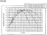
- FIGS. 19 and 20 are graphs each showing a relationship between a Fe concentration of the magnetostrictive film 2 of the magnetic structure 20 and an output of the torque sensor 1 using the magnetic structure 20.
- FIG. 19 shows outputs of torque sensors 1 using the magnetic structures 20 including the magnetostrictive films 2 having Fe concentration differences of about 2%, about 3%, or about 4.5%.
- FIG. 20 shows outputs of torque sensors 1 using the magnetic structures 20 including the magnetostrictive films 2 having Fe concentration differences of about 5%, about 7%, or about 8%.
- FIG. 19 shows outputs of torque sensors 1 using the magnetic structures 20 including the magnetostrictive films 2 having Fe concentration differences of about 5%, about 7%, or about 8%.
- the abscissa represents a Fe concentration in a center portion of a randomly selected one of the magnetostrictive lines 2a of the magnetostrictive film 2 (center portion in the width direction of the magnetostrictive line 2a in the cross section illustrated in FIG. 4 ).
- an output of 3 V or more was obtained in a case where the Fe concentration in the center portion of the magnetostrictive line 2a was about 24% to about 31%.
- an output of 3 V or more was obtained in a case where the Fe concentration in the center portion of the magnetostrictive line 2a was about 24.5% to about 32.5%.
- an output of 3V or more was obtained in a case where the Fe concentration in the center portion of the magnetostrictive line 2a was about 26.5% to about 37.5%.
- the difference between the maximum value and the minimum value of the Fe concentration in the center portion of the magnetostrictive line 2a in a case where an output of the torque sensor 1 is 3 V or more will be hereinafter referred to as a control range of the Fe concentration.
- the control range is about 7%. In the magnetostrictive film 2 having a Fe concentration difference of about 7%, the control range is about 10%. In the magnetostrictive film 2 having a Fe concentration difference of about 8%, the control range is about 13%.
- the present invention is applicable to, for example, a magnetostrictive sensor for use in an electric motor-assisted bicycle.
Landscapes
- Physics & Mathematics (AREA)
- Electromagnetism (AREA)
- General Physics & Mathematics (AREA)
- Engineering & Computer Science (AREA)
- Chemical & Material Sciences (AREA)
- Combustion & Propulsion (AREA)
- Transportation (AREA)
- Mechanical Engineering (AREA)
- Power Steering Mechanism (AREA)
- Force Measurement Appropriate To Specific Purposes (AREA)
- Measuring Magnetic Variables (AREA)
Abstract
Description
- The present invention relates to a magnetostrictive sensor, a magnetic structure, a method for fabricating the magnetic structure, a motor-driven unit including the magnetostrictive sensor, and an electric motor-assisted bicycle including the magnetostrictive sensor.
- A magnetostrictive sensor is typically used for detecting a torque or a load. In many magnetostrictive sensors, a magnetostrictive portion containing a magnetostrictive material is formed on an outer peripheral surface of a member (base material) on which a torque or a load acts. In a magnetostrictive sensor having such a structure, a coil is disposed to surround the base material on which the magnetostrictive portion is formed.
- The above-described structure of the magnetostrictive sensor causes a magnetic permeability of the magnetostrictive material of the magnetostrictive portion to change when a force acts on the base material on which the magnetostrictive portion is formed. Accordingly, the impedance of the coil disposed to surround the magnetostrictive portion changes. The magnetostrictive sensor detects the change in the impedance of the coil, thereby detecting a torque or a load.
- Sensitivity of such a magnetostrictive sensor is affected by a magnetostriction constant and a magnetic permeability of a magnetostrictive material. The magnetostriction constant and the magnetic permeability of the magnetostrictive material vary depending on a chemical composition of the magnetostrictive material. For example, as disclosed in Non-patent Document 1, a Fe-Ni alloy shows significant changes of the magnetostriction constant and the magnetic permeability depending on the Ni content in the alloy. As also disclosed in
Non-patent Document 2, for example, a Fe-Co alloy shows significant changes of the magnetostriction constant and the magnetic permeability depending on the Co content in the alloy. - In view of this, in techniques employed to date, the chemical composition of the magnetostrictive material for use in a magnetostrictive sensor is adjusted to increase sensitivity of the magnetostrictive sensor. Specifically, the chemical composition of the magnetostrictive material is adjusted in such a manner that the magnetostriction constant and the magnetic permeability have values suitable for increasing sensitivity of the magnetostrictive sensor.
- For example, Patent Document 1 discloses a magnetostrictive torque sensor including a magnetostrictive film made of a Ni-Fe alloy. In the magnetostrictive torque sensor of Patent Document 1, the chemical composition of the Ni-Fe alloy (magnetostrictive film) is adjusted in such a manner that the product of the magnetostriction constant and the magnetic permeability is 90% or more of the maximum value thereof.
- Patent Document 1: Japanese Patent Application Publication No.
2007-93244 -
- Non-patent Document 1: Chikazumi, Soshin et al., Handbook of Magnetic Material, Asakura Publishing Co., Ltd., New Edition, April 1, 2006, pp.1082-1083
- Non-patent Document 2: RICHARD M. BOZORTH, Ferromagnetism, 1993, Editorial Board Institute of Electrical and Electronics Engineers, pp. 197, 664 (1993)
- Through examination of manufacturing magnetostrictive sensors, there arose a demand for more efficiently manufacturing magnetostrictive sensors with high sensitivity.
- It is therefore an object of the present invention to obtain a configuration that enables efficient manufacturing of magnetostrictive sensors with high sensitivity.
- It has been known to date that there is a combination of a magnetostriction constant and a magnetic permeability suitable for increasing sensitivity of a magnetostrictive sensor including a magnetostrictive portion made of a predetermined magnetostrictive material. In addition, as described above, the magnetostriction constant and the magnetic permeability vary depending on the chemical composition of the magnetostrictive material. Thus, the magnetostrictive portion has been formed to date in such a manner that the magnetostrictive material has a predetermined chemical composition in the entire magnetostrictive portion to obtain a magnetostriction constant and a magnetic permeability suitable for increasing sensor sensitivity.
- On the other hand, unless the magnetostrictive material cannot be adjusted to have a predetermined chemical composition in forming the magnetostrictive portion, sensitivity of the magnetostrictive sensor cannot be sufficiently increased. Thus, to increase sensitivity of the magnetostrictive sensor, it has been necessary to date to strictly control the chemical composition of the magnetostrictive material in forming the magnetostrictive portion. That is, an increase in sensitivity of a magnetostrictive sensor and facilitation of manufacturing the magnetostrictive sensor cannot be achieved at the same time in techniques employed to date.
- In view of this, inventors of the present invention conducted various studies to achieve both an increase in sensitivity of a magnetostrictive sensor and facilitation of manufacturing of the magnetostrictive sensor at the same time. Through the studies, the chemical composition of the magnetostrictive material constituting the magnetostrictive portion was investigated in detail again. Consequently, it was found that a stress occurs inside the magnetostrictive portion when the magnetostrictive portion includes portions having different chemical compositions of the magnetostrictive material. More specifically, it was found that in a magnetostrictive portion made of a magnetostrictive material including a plurality of elements, the presence of portions having different concentrations of one of the elements causes a stress inside the magnetostrictive portion.
- Further investigation of the inventors on the magnetostrictive portion shows that in the magnetostrictive sensor including the magnetostrictive portion in which an internal stress occurs as described above, sensor sensitivity can be increased without strict control of the chemical composition of the magnetostrictive material in forming the magnetostrictive portion. Specifically, it was found that sensor sensitivity can be sufficiently increased even if the chemical composition of the magnetostrictive material deviates to some degree from a target chemical composition (e.g., chemical composition theoretically determined in order to increase the sensor sensitivity). That is, the inventors found that generation of a stress inside the magnetostrictive portion can achieve both an increase in sensitivity of the magnetostrictive sensor and facilitation of manufacturing of the magnetostrictive sensor at the same time.
- Based on the foregoing findings, inventors arrived at a configuration of a magnetostrictive sensor described below.
- A magnetostrictive sensor according to an embodiment of the present invention includes a magnetic structure including a columnar base material extending along an axis and a magnetostrictive portion disposed on an outer peripheral surface of the base material and containing a plurality of elements. The magnetostrictive portion includes a plurality of portions having different concentrations of at least one of the plurality of elements. In the magnetic structure, suppose a cross section orthogonal to the axis is a first cross section and a cross section orthogonal to the first cross section and passing through the axis is a second cross section, the magnetostrictive portion satisfies at least one of requirements (A), (B), and (C):
- (A) in the first cross section, portions having different concentrations of the at least one element are arranged clockwise about the axis,
- (B) in the first cross section, portions having different concentrations of the at least one element are arranged in a thickness direction of the magnetostrictive portion, and
- (C) in the second cross section, portions having different concentrations of the at least one element are arranged along the axis.
- A magnetostrictive sensor according to an embodiment of the present invention can have increased sensitivity and can be manufactured efficiently.
-
-
FIG. 1 is a partial cross-sectional view schematically illustrating a configuration of a magnetostrictive sensor according to an embodiment of the present invention. -
FIG. 2 schematically illustrates a configuration of a magnetic structure. -
FIG. 3 is a view of a magnetostrictive film seen in a direction orthogonal to an axis of the magnetic structure. -
FIG. 4 schematically illustrates a cross section of the magnetic structure. -
FIG. 5 illustrates a cross section taken along line D-D inFIG. 2 . -
FIG. 6 illustrates another example of the cross section taken along line D-D inFIG. 2 . -
FIG. 7 illustrates a cross section taken along line E-E inFIG. 2 . -
FIG. 8 illustrates another example of the cross section taken along line D-D inFIG. 2 . -
FIG. 9 illustrates a simplified cross section taken along line D-D inFIG. 2 . -
FIG. 10 shows views for describing a method for fabricating a magnetic structure. -
FIG. 11 schematically illustrates a configuration of a circuit for converting an impedance change of a coil to a voltage in the torque sensor illustrated inFIG. 1 . -
FIG. 12 schematically illustrates a configuration of an electric motor-assisted bicycle. -
FIG. 13 is a block diagram schematically illustrating a configuration of a motor-driven unit. -
FIG. 14 is a cross section illustrating another example of the magnetic structure. -
FIG. 15 is a cross section illustrating yet another example of the magnetic structure. -
FIG. 16 illustrates still another example of the magnetic structure. -
FIG. 17 is a graph showing change in Fe concentrations in magnetostrictive lines. -
FIG. 18 is a graph showing change in Fe concentrations in magnetostrictive lines. -
FIG. 19 is a graph showing relationships between the Fe concentration of a magnetostrictive film of the magnetic structure and the output of the torque sensor. -
FIG. 20 is a graph showing relationships between the Fe concentration of the magnetostrictive film of the magnetic structure and the output of the torque sensor. -
FIG. 21 is a graph showing relationships between the Fe concentration difference and the control range of the Fe concentration. -
FIG. 22 is a graph showing relationships between the Fe concentration difference and the control range of the Fe concentration. - An embodiment of the present invention will be described in detail with reference to the drawings. In the following description, dimensions of components in each drawing do not strictly represent actual dimensions of components, dimensional ratios of components, and the like.
-
FIG. 1 is a partial cross-sectional view schematically illustrating a configuration of a magnetostrictive sensor according to an embodiment of the present invention. The following description is directed to a magnetostrictive torque sensor (hereinafter referred to simply as a "torque sensor" in some cases) 1 for detecting a torque acting on abase material 21 attached to an unillustrated rotating shaft, as an example of a magnetostrictive sensor.FIG. 1 schematically illustrates a configuration of the torque sensor 1 for description. - As illustrated in
FIG. 1 , the torque sensor 1 includes amagnetic structure 20 including a magnetostrictive film 2 (magnetostrictive portion) and adetection unit 30 includingcoils magnetic structure 20 is formed in a cylindrical shape extending along an axis A. Themagnetic structure 20 is disposed on an outer peripheral surface of an unillustrated rotating shaft. -
FIG. 2 schematically illustrates a configuration of themagnetic structure 20. Themagnetic structure 20 includes acylindrical base material 21 extending along the axis A (i.e., extending axially) and themagnetostrictive film 2. The configuration of themagnetic structure 20 will be described in detail later. As illustrated inFIG. 2 , themagnetostrictive film 2 is disposed on an outerperipheral surface 21s of thecylindrical base material 21. Themagnetostrictive film 2 includes a plurality ofmagnetostrictive lines 2a whose configuration will be described in detail later. -
FIG. 3 illustrates themagnetostrictive film 2 of themagnetic structure 20 seen in a direction orthogonal to the axis A (seeFIG. 1 ). The pattern of themagnetostrictive film 2 illustrated inFIG. 3 is an example. As illustrated inFIG. 3 , themagnetostrictive film 2 includes the plurality ofmagnetostrictive lines 2a each having a length of L = (L1 + L2) (where L1 = L2 in the example ofFIG. 3 ) and a width W. The plurality ofmagnetostrictive lines 2a extend in directions intersecting the axis A when viewed in the direction orthogonal to the axis A. InFIG. 3 , an interspace between adjacent ones of themagnetostrictive lines 2a is expressed as an interspace I. - The
magnetostrictive film 2 includes tworegions base material 21. The plurality ofmagnetostrictive lines 2a are formed across the tworegions magnetostrictive lines 2a in one region and themagnetostrictive lines 2a in the other region are symmetric with respect to the center line of themagnetostrictive film 2 in the axial direction. That is, each of themagnetostrictive lines 2a of themagnetostrictive film 2 is formed in a V shape when viewed in the direction orthogonal to the axis A (in the state illustrated inFIG. 3 ). - With the above-described arrangement of the
magnetostrictive lines 2a of themagnetostrictive film 2, when a torsional torque is applied to thebase material 21 through the rotating shaft, one of a tensile force and a compressive force is applied to themagnetostrictive lines 2a in theregion 2b of themagnetostrictive film 2 in its extension direction. To themagnetostrictive lines 2a in theregion 2c of themagnetostrictive film 2, the other one of the tensile force and the compressive force is applied in the extension direction. In this manner, magnetic permeability varies in themagnetostrictive lines 2a in theregions magnetostrictive film 2. - The
detection unit 30 includes the twocylindrical coils yoke 5. As illustrated inFIG. 1 , thecoils magnetic structure 20. In the example ofFIG. 1 , thecoils magnetic structure 20. Specifically, as illustrated inFIG. 1 , thecoils magnetic structure 20 in such a manner that thecoil 3 surrounds oneregion 2b of themagnetostrictive film 2 and thecoil 4 surrounds theother region 2c of themagnetostrictive film 2. Theyoke 5 has a recess in which thecoils coils tubular yoke 5. - The
coils power supply 6 as illustrated inFIG. 11 to thereby generate an AC magnetic field around thecoils coils yoke 5, and thebase material 21 constitute a magnetic circuit. As illustrated inFIG. 11 , thecoils torque detection circuit 7. -
FIG. 11 illustrates an example of a configuration of an electronic circuit included in the torque sensor 1. The circuit configuration illustrated inFIG. 11 is widely known as the electronic circuit included in the torque sensor 1. The circuit illustrated inFIG. 11 includes theAC power supply 6 and thetorque detection circuit 7. TheAC power supply 6 applies an AC voltage to thecoils torque detection circuit 7 detects a voltage generated in thecoils base material 21. Thetorque detection circuit 7 obtains a voltage difference Vout between thecoils base material 21 by using an unillustrated arithmetic circuit. The electronic circuit included in the torque sensor 1 is not limited to the configuration illustrated inFIG. 11 . - As described above, when a torsional torque is applied to the
base material 21 through the rotating shaft, one of a tensile force and a compressive force is applied to themagnetostrictive lines 2a in theregions magnetostrictive film 2 in the torque sensor 1 in the extension direction of themagnetostrictive lines 2a. Thus, a change in magnetic permeability occurring in themagnetostrictive lines 2a differs between theregions magnetostrictive film 2. Such a difference in the magnetic permeability change is detected as a voltage difference between thecoils torque detection circuit 7. Thus, thetorque detection circuit 7 can detect the torsional torque applied to thebase material 21. - More specifically, when a torque acts on the
base material 21, a tensile stress occurs in themagnetostrictive lines 2a in one of theregions magnetostrictive film 2, and thus, the magnetic permeability of thesemagnetostrictive lines 2a increases. A compressive stress acts on themagnetostrictive lines 2a in the other region, and thus, the magnetic permeability of thesemagnetostrictive lines 2a decreases. Consequently, a difference occurs between impedances of the twocoils coils torque detection circuit 7 as a value in accordance with the torque acting on thebase material 21. InFIG. 11 , suppose Vout at a torque of zero is V0 and Vout at an input of a rated torque is Vt, Vt-V0 is an output range of the torque sensor 1. - The arrangement of the components in the torque sensor 1 illustrated in
FIG. 1 is an example. The numbers and arrangements, for example, of thecoils yoke 5 are not limited to those in the configuration illustrated inFIG. 1 , and may be changed as necessary by those skilled in the art. - The length L/width W of the
magnetostrictive lines 2a of themagnetostrictive film 2 illustrated inFIG. 3 satisfies, for example, Expression (2) below. Themagnetostrictive lines 2a extend in a first direction intersecting the axis A in theregion 2b of themagnetostrictive film 2 when viewed in the direction orthogonal to the axis A. Themagnetostrictive lines 2a extend in a second direction intersecting the first direction in theregion 2c of themagnetostrictive film 2 when viewed in the direction orthogonal to the axis A. That is, themagnetostrictive lines 2a have bending portions Z each bending at an angle θ, in a center portion of themagnetostrictive film 2 in the axial direction of thebase material 21. Themagnetostrictive film 2 is formed to have a coverage percentage defined in Equation (1) of 30% or more and 95% or less. - In the example illustrated in
FIG. 3 , when viewed in the direction orthogonal to the axis A, themagnetostrictive lines 2a extend from an end X of themagnetostrictive film 2 in the axial direction to the center portion (bending portions Z of themagnetostrictive lines 2a) of themagnetostrictive film 2 in the axial direction across the axis A, in theregion 2b of themagnetostrictive film 2. The extension direction of themagnetostrictive lines 2a in theregion 2b of themagnetostrictive film 2 corresponds to the first direction described above. When viewed in the direction orthogonal to the axis A, themagnetostrictive lines 2a extend in a direction at an angle θ relative to the first direction, that is, extend from the center portion (bending portions Z of themagnetostrictive lines 2a) of themagnetostrictive film 2 in the axial direction to the other end Y of themagnetostrictive film 2 in the axial direction across the axis A, in theregion 2c of themagnetostrictive film 2. The extension direction of themagnetostrictive lines 2a in theregion 2c of themagnetostrictive film 2 corresponds to the second direction described above. - As described above,
FIG. 3 illustrates an example of themagnetostrictive film 2 in which themagnetostrictive lines 2a have the bending portions Z. Here, the bending portions Z are intersection offirst portions 2m (magnetostrictive lines 2a in theregion 2b) andsecond portions 2n (magnetostrictive lines 2a in theregion 2c) of themagnetostrictive lines 2a. That is, in themagnetostrictive film 2 illustrated inFIG. 3 , eachmagnetostrictive line 2a includes thefirst portion 2m extending from one end X of themagnetostrictive film 2 in the axial direction to the bending portion Z and thesecond portion 2n extending from the bending portion Z to the other end Y of themagnetostrictive film 2 in the axial direction. - coverage percentage = area of region in contact with
magnetostrictive film 2 on outerperipheral surface 21s ofbase material 21/total area (%) of outerperipheral surface 21 s

- In the
magnetostrictive film 2 illustrated inFIG. 3 , the length L/width W of themagnetostrictive lines 2a is the sum of the length/width of themagnetostrictive lines 2a in thefirst portions 2m and the length/width of themagnetostrictive lines 2a in thesecond portions 2n. The length/width of eachmagnetostrictive line 2a in thefirst portion 2m can be obtained by (length L1 ofmagnetostrictive line 2a from end X to bending portion Z illustrated inFIG. 3 )/(width ofmagnetostrictive line 2a infirst portion 2m). The length/width of eachmagnetostrictive line 2a in thesecond portion 2n can be obtained by (length L2 ofmagnetostrictive line 2a from bending portion Z to end Y illustrated inFIG. 3 )/(width ofmagnetostrictive line 2a insecond portion 2n). - If the coverage percentage defined by Equation (1) is within the above-described range (30% or more and 95% or less), the torque sensor 1 having high sensitivity can be obtained. That is, in Equation (1), if the coverage percentage is 30% or more, sufficient sensitivity of the torque sensor 1 can be obtained. If the coverage percentage is 95% or less, the shape of the
magnetostrictive film 2 does not vary easily. Accordingly, if the coverage percentage is 95% or less, adjacent ones of themagnetostrictive lines 2a do not contact each other, and thus, sufficient sensitivity of the torque sensor 1 can be obtained. The coverage percentage is preferably 50% or more. The coverage percentage is more preferably 60% or more. The coverage percentage is preferably 93% or less. The coverage percentage is more preferably 90% or less. The coverage percentage is much more preferably 85% or less. - Since the length L/width W is within the range defined by Expression (2), the torque sensor 1 having high sensitivity can be obtained. In Expression (2), if the length L/width W is 30 or more, sufficient sensitivity of the torque sensor 1 can be obtained. If the length L/width W is 120 or less, the
magnetostrictive film 2 can be easily fabricated. The length L/width W is preferably less than 95. The length L/width W is more preferably less than 85. The length L/width W is preferably 43 or more. The length L/width W is more preferably 53 or more. The length L/width W is much more preferably 75 or more. - From the viewpoint of further increasing sensitivity, in the case where the
magnetostrictive line 2a has the bending portion Z, the angle formed by the first direction and the second direction in the bending portion Z of themagnetostrictive line 2a (0 inFIG. 3 , i.e., an angle formed by thefirst portion 2m and thesecond portion 2n) is preferably 60° or more and 120° or less. The angle is more preferably 80° or more. The angle is preferably 100° or less. In the case where themagnetostrictive line 2a does not have a bending portion (e.g., a magnetostrictive line 902a of a magnetostrictive film 902 illustrated inFIG. 12 ), if the angle formed by thefirst portion 2m and thesecond portion 2n is within the range described above, sensitivity of the torque sensor 1 can be further increased. - From the viewpoint of further increasing sensitivity of the torque sensor 1, in each
magnetostrictive line 2a, the absolute value of an angle θ1 formed by the axis A and the first direction when viewed in the direction orthogonal to the axis A of thebase material 21 is preferably 30° or more and 60° or less (more preferably the angle θ1 is ±45°) as illustrated inFIG. 3 . The absolute value of an angle θ2 formed by thebase material 21 and the second direction is preferably 30° or more and 60° or less (more preferably angle θ2 is ±45°). - The
magnetostrictive film 2 illustrated inFIG. 3 further includes connectingparts 26 each connecting ends of adjacent ones of themagnetostrictive lines 2a in the axial direction. In themagnetostrictive film 2 illustrated inFIG. 3 , the connectingparts 26 are disposed at both axial ends of themagnetostrictive lines 2a. Since the connectingparts 26 connecting the plurality ofmagnetostrictive lines 2a are provided in themagnetostrictive film 2, the plurality ofmagnetostrictive lines 2a are not easily separated from thebase material 21. Thus, strength ofmagnetostrictive film 2 can be enhanced. -
FIG. 4 schematically illustrates a cross section of themagnetic structure 20 illustrated inFIG. 1 . The cross section illustrated inFIG. 4 is obtained by cutting themagnetic structure 20 in a plane orthogonal to the extension direction of themagnetostrictive lines 2a. More specifically, the cross section illustrated inFIG. 4 is a cross section in a case where themagnetostrictive lines 2a are cut in a plane perpendicular to the first direction (i.e., direction from the end X of themagnetostrictive film 2 to the bending portions Z inFIG. 2 ), that is, a cross section taken along line C-C inFIG. 3 in a direction perpendicularly to the drawing sheet. As illustrated inFIG. 4 , themagnetic structure 20 includes thecylindrical base material 21 and themagnetostrictive film 2 disposed on the outerperipheral surface 21s of thebase material 21. InFIG. 4 , "M" corresponds to "W" inFIG. 3 . - The
magnetostrictive film 2 is made of a material including a magnetic material. For example, the magnetic material preferably includes at least one of the metals selected from the group consisting essentially of Ni, Fe, Co, and Cr. In this embodiment, themagnetostrictive film 2 includes a plurality of elements. At least one of the elements is preferably an element forming a ferromagnet, for example. In this case, sensitivity of the torque sensor 1 can be increased. The element forming a ferromagnet is, for example, Fe, Co, or Ni. From the viewpoint of obtaining higher magnetic permeability and higher magnetostrictive effect, the magnetic material more preferably includes Fe and at least one of the metals selected from the group consisting essentially of Ni, Co, and Cr. Themagnetostrictive film 2 may include a metal such as Al, Ti, Ge, Mo, Ag, or Cu and/or a nonmetal material such as Si, B, S, C, O, or N. - For example, in a case where the
magnetostrictive film 2 contains Fe, from the viewpoint of obtaining higher magnetic permeability and higher magnetostrictive effect, the Fe content (concentration) of themagnetostrictive film 2 is preferably 20 mass% or more and 40 mass% or less. The Fe content is more preferably 23 mass% or more. The Fe content is much more preferably 26 mass% or more. The Fe content is more preferably 36 mass% or less. The Fe content is much more preferably 33 mass% or less. The total content (concentration) of metals except Fe is preferably 60 mass% or more and 80 mass% or less. The total content of metals except Fe is more preferably 64 mass% or more. The total content of metals except Fe is much more preferably 67 mass% or more. The total content of metals except Fe is more preferably 77 mass% or less. The total content of metals except Fe is much more preferably 74 mass% or less. As described above, the metals except Fe preferably include at least one selected from the group consisting essentially of Ni, Co, and Cr. - In a case where the
magnetostrictive film 2 contains Fe and Ni, the Ni content (concentration) is preferably 60 mass% or more and 80 mass% or less. The Ni content is more preferably 64 mass% or more. The Ni content is much more preferably 67 mass% or more. The Ni content is more preferably 77 mass% or less. The Ni content is much more preferably 74 mass% or less. - In a case where the
magnetostrictive film 2 contains S, the S content (concentration) of themagnetostrictive film 2 is preferably 0.03 mass% or more and 0.12 mass% or less. The S content is more preferably 0.04 mass% or more and 0.10 mass% or less. The S content is much more preferably 0.05 mass% or more and 0.09 mass% or less. - The preferable concentration and more preferable concentration of each element described above refer to concentrations of the element in a center portion mc of each
magnetostrictive line 2a (seeFIG. 4 ). In the cross section illustrated inFIG. 4 , the center portion mc is a center portion of eachmagnetostrictive line 2a in the thickness direction and the width direction. - The concentration (content) of each element in the
magnetostrictive film 2 can be measured with a known element analyzer. Specifically, the concentration of each element can be measured with an electron probe microanalyzer (EPMA), for example. In the case of measuring the concentration of each element with the EPMA, the spot diameter is set at 10 µm or less (preferably 5 µm or less). - The maximum thickness H of the magnetostrictive film 2 (the distance from the surface of the
magnetostrictive film 2 contacting thebase material 21, i.e., the outerperipheral surface 21s of thebase material 21, to the tip of projection of themagnetostrictive film 2 outward in the radial direction of the base material 21) is, for example, 20 µm or more and 200 µm or less. The maximum thickness H is preferably 40 µm or more. The maximum thickness H is more preferably 60 µm or more. The maximum thickness H is preferably 140 µm or less. The maximum thickness H is more preferably 100 µm or less. - As illustrated in
FIG. 4 , when themagnetostrictive lines 2a of themagnetostrictive film 2 is viewed in a cross section taken orthogonally to the extension direction of themagnetostrictive lines 2a, themagnetostrictive lines 2a have portions outside in the radial direction of thebase material 21 that are longer than portions of themagnetostrictive lines 2a near thebase material 21, in the direction orthogonal to the radial direction of the base material 21 (direction parallel to the outerperipheral surface 21s of the base material 21). Specifically, themagnetostrictive lines 2a haveprojections 2e individually projecting from bodies of themagnetostrictive lines 2a on thebase material 21 in opposite directions orthogonal to the radial direction of thebase material 21. The presence of theprojections 2e of themagnetostrictive lines 2a increases the surface area of themagnetostrictive lines 2a. In addition, the presence of theprojections 2e of themagnetostrictive lines 2a can also reduce the amount of change in output of the torque sensor 1 with respect to a change in concentration of each element in themagnetostrictive film 2. - An angle θe formed by the interface between the
magnetostrictive lines 2a and thebase material 21 and the projecting direction of theprojections 2e is preferably an acute angle (less than 90°). In this case, from the viewpoint of further enhancing sensitivity of the sensor, the angle θe is more preferably greater than 0° and less than or equal to 45°. The angle θe is much more preferably 30° or less. - Since the
magnetostrictive lines 2a of themagnetostrictive film 2 have theprojections 2e described above, in the cross section illustrated inFIG. 4 , the width M at a predetermined distance from the outerperipheral surface 21s of thebase material 21 in the radial direction of the base material 21 (thickness direction of themagnetostrictive line 2a) is larger than a width N of acontact area 2f between themagnetostrictive film 2 and the outerperipheral surface 21s of thebase material 21. - That is, when the
magnetostrictive lines 2a are viewed in the cross section taken orthogonally to the extension direction thereof (i.e., cross section illustrated inFIG. 4 ), the plurality ofmagnetostrictive lines 2a of themagnetostrictive film 2 has the length of a longest portion (length M at the predetermined distance described above, which will be hereinafter referred to as a maximum width M) that is larger than the length N of thecontact area 2f between themagnetostrictive film 2 and the outerperipheral surface 21s of thebase material 21, in the direction orthogonal to the radial direction of thebase material 21. The maximum width M is larger than the length of the interspace d between adjacentmagnetostrictive lines 2a. The interspace d between adjacentmagnetostrictive lines 2a refers to an interspace from thecontact area 2f between themagnetostrictive line 2a and thebase material 21 to thecontact area 2f between its adjacentmagnetostrictive line 2a and thebase material 21. - In the
magnetostrictive film 2, themagnetostrictive lines 2a having the shape described above can enhance sensitivity of the torque sensor 1. That is, when themagnetostrictive lines 2a are viewed in the cross section taken orthogonally to the extension direction of themagnetostrictive lines 2a, the maximum width M of themagnetostrictive lines 2a in themagnetostrictive film 2 is larger than the length of the interspace d between adjacentmagnetostrictive lines 2a. In such a configuration, the interspace d between themagnetostrictive lines 2a is relatively narrow. In such a case where the interspace d between adjacentmagnetostrictive lines 2a is narrow, the maximum width M of themagnetostrictive lines 2a can be made larger than the length N of thecontact area 2f between themagnetostrictive film 2 and the outerperipheral surface 21s of thebase material 21 so that the surface area of themagnetostrictive lines 2a, that is, the surface area of themagnetostrictive film 2, can be increased. The increase in the surface area of themagnetostrictive film 2 enables the magnetic permeability of themagnetostrictive film 2 to vary in a wide range. In this manner, a change in magnetic permeability upon application of a force to themagnetostrictive film 2 can be easily detected. Thus, sensitivity of the torque sensor 1 can be enhanced. - In other words, with the configuration described above, sensitivity of the torque sensor 1 can be enhanced without changes in the coverage percentage defined in Equation (1) and the value of length L/width W defined in Expression (2).
- The length of the interspace d from the
contact area 2f between onemagnetostrictive line 2a and the outerperipheral surface 21s of thebase material 21 to thecontact area 2f between its adjacentmagnetostrictive line 2a and the outerperipheral surface 21s of thebase material 21 is larger than the sum of the length of theprojection 2e of onemagnetostrictive line 2a projecting toward its adjacentmagnetostrictive line 2a and the length of theprojection 2e of the adjacentmagnetostrictive line 2a projecting toward themagnetostrictive line 2a. - In this manner, in adjacent
magnetostrictive lines 2a, contact between theprojections 2e can be prevented. - When viewed in the cross section illustrated in
FIG. 4 , themagnetostrictive lines 2a has a maximum width M larger than the height (maximum thickness) H of themagnetostrictive lines 2a in the thickness direction. In this manner, themagnetostrictive lines 2a are formed in a flat shape that is longer in the direction (direction parallel to the outerperipheral surface 21s of the base material 21) orthogonal to the radial direction of thebase material 21 than in the thickness direction. Accordingly, the surface area of themagnetostrictive lines 2a can be further increased. Thus, a change in magnetic permeability upon application of a force to themagnetostrictive film 2 can be more easily detected. - In the cross section of
FIG. 4 , from the viewpoint of further enhancing sensitivity of the sensor, the ratio H1/H between the maximum thickness H of themagnetostrictive line 2a and the height of ends me of themagnetostrictive line 2a (distance from the interface between themagnetostrictive line 2a and thebase material 21 to the tip of theprojection 2e, i.e., the height from the outerperipheral surface 21s of thebase material 21 to the position of the maximum width M) H1 is less than one. The Hi/H is preferably 0.8 or less. The H1/H is more preferably 0.5 or less. The Hi/H is much more preferably 0.3 or less. On the other hand, the Hi/H is preferably 0.015 or more. - The
magnetostrictive lines 2a are formed in such a manner that the ratio H1/H is within the ranges described above so that the surface area of themagnetostrictive lines 2a can be further increased. Thus, a change in magnetic permeability upon application of a force to themagnetostrictive film 2 can be more easily detected. - By setting Hi/H at 0.5 or less, that is, by setting a half height of the maximum thickness H of the
magnetostrictive lines 2a at a position higher than or equal to the maximum width M from the outerperipheral surface 21s of thebase material 21, a portion having a width larger than that of thecontact area 2f between themagnetostrictive line 2a and the outerperipheral surface 21s of thebase material 21 can be provided in a wide range in the thickness direction of themagnetostrictive line 2a. Accordingly, the surface area of themagnetostrictive lines 2a can be further increased. Thus, a change in magnetic permeability upon application of a force to themagnetostrictive films 2 can be more easily detected. - In this embodiment, the
magnetostrictive film 2 has portions having different concentrations of at least one of a plurality of elements. This will be specifically described with reference to the drawings. -
FIGS. 5 and6 illustrate cross sections taken along line D-D inFIG. 2 (cross sections orthogonal to the axis A of the magnetic structure 20: hereinafter also referred to as a first cross section).FIGS. 5 and6 illustrate one of themagnetostrictive lines 2a and its peripheral portion in the D-D cross section ofFIG. 2 in an enlarged manner. - With reference to
FIG. 5 , in the first cross section of themagnetic structure 20, themagnetostrictive line 2a is divided into a plurality ofportions FIG. 5 ) about the axis A (seeFIG. 1 ), for example. In this case, in this embodiment, the concentration of at least one of a plurality of elements differs between theportion 22a and theportion 22b and also differs between theportion 22b and the portion 22c. That is, in this embodiment, in the first cross section of themagnetic structure 20, portions having different concentrations of the at least one element are arranged clockwise about the axis A. - The concentration of the at least one element may be highest in the
portion 22a, highest in theportion 22b, or highest in the portion 22c. The concentration of the at least one element may change in the clockwise direction in each of theportions base material 21. - For example, in the first cross section of the
magnetic structure 20, the concentration of at least one element may be highest at or near the center of themagnetostrictive line 2a in the clockwise direction and may be lowest at or near an end of themagnetostrictive line 2a in the clockwise direction. Alternatively, in the first cross section of themagnetic structure 20, the concentration of at least one element may be lowest at or near the center of themagnetostrictive line 2a in the clockwise direction and may be highest at or near an end of themagnetostrictive line 2a in the clockwise direction. The difference between the concentration of the at least one element at the center of themagnetostrictive line 2a and the concentration of the at least one element at the end of themagnetostrictive line 2a is preferably 1 mass% or more, and more preferably 2 mass% or more. The concentration difference is, for example, a value less than or equal to the concentration of the at least one element at the center of themagnetostrictive line 2a. - The concentration of the at least one element may be the same in two of the plurality of
portions magnetostrictive line 2a with respect to the center line of themagnetostrictive line 2a in the lateral direction. - The concentration distribution of each element in the
magnetostrictive film 2 is not limited to those of the examples described with reference toFIG. 5 . For example, as illustrated inFIG. 6 , suppose themagnetostrictive line 2a is divided into a plurality ofportions magnetostrictive film 2, the concentration of at least one of a plurality of elements may differ between theportion 22d and theportion 22e and differ between theportion 22e and theportion 22f. That is, in the first cross section, portions having different concentrations of the at least one element may be arranged in the thickness direction of themagnetostrictive film 2. Although not described in detail, in a manner similar to that inFIG. 5 , a portion having the highest concentration of the at least one element may be any one of the plurality ofportions portions - Alternatively, portions having different concentrations of the at least one element may be arranged along the axis A (see
FIG. 1 ), for example. This will be briefly described with reference to the drawings. -
FIG. 7 illustrates a cross section taken along line E-E inFIG. 2 (cross section orthogonal to the first cross section and passing through the axis A, which will be hereinafter referred to as a second cross section).FIG. 7 illustrates one of themagnetostrictive lines 2a and its peripheral portion in the E-E cross section ofFIG. 2 in an enlarged manner. - With reference to
FIG. 7 , in the second cross section of themagnetic structure 20, suppose themagnetostrictive line 2a is divided into threeportions 22g, 22h, and 22i along the axis A (seeFIG. 1 ), for example, the concentration of at least one of a plurality of elements may differ between the portion 22g and theportion 22h and differ between theportion 22h and the portion 22i. Although not described in detail, in a manner similar to that inFIG. 5 , a portion having the highest concentration of the at least one element may be any one of the plurality ofportions 22g, 22h, and 22i. The concentration of the at least one element may be the same in two of the plurality ofportions 22g, 22h, and 22i. -
FIG. 5 shows the case where the three portions having different concentrations of at least one element are arranged in the clockwise direction in themagnetostrictive line 2a. Alternatively, in themagnetostrictive line 2a, two or four or more portions having different concentrations of at least one element may be arranged in the clockwise direction. The expression "portions having different concentrations of an element are arranged clockwise about the axis" refers to a situation where portions having different concentrations of an element are present in the clockwise direction. The configuration in which "portions having different concentrations of an element are arranged clockwise about the axis" includes not only a configuration in which the element concentration changes stepwise in the clockwise direction but also a configuration in which the element concentration changes continuously in the clockwise direction. -
FIG. 6 shows the case where the three portions having different concentrations of at least one element are arranged in the thickness direction in themagnetostrictive line 2a. Alternatively, in themagnetostrictive line 2a, two or four or more portions having different concentrations of at least one element may be arranged in the thickness direction. The expression "portions having different concentrations of an element are arranged in the thickness direction of the magnetostrictive portion" refers to a situation where portions having different concentrations of an element are present in the thickness direction. The configuration in which "portions having different concentrations of an element are arranged in the thickness direction of the magnetostrictive portion" includes not only a configuration in which the element concentration changes stepwise in the thickness direction but also a configuration in which the element concentration changes continuously in the thickness direction. -
FIG. 7 shows the case where the three portions having different concentrations of at least one element are arranged along the axis A (seeFIG. 1 ) in themagnetostrictive line 2a. Alternatively, in themagnetostrictive line 2a, two or four or more portions having different concentrations of at least one element may be arranged along the axis A. The expression "portions having different concentrations of an element are arranged along the axis" refers to a situation where portions having different concentrations of an element are present in the axis direction. The configuration in which "portions having different concentrations of an element are arranged along the axis" includes not only a configuration in which the element concentration changes stepwise in the axis direction but also a configuration in which the element concentration changes continuously in the axis direction. - Although not described in detail, in a manner similar to that in
FIG. 8 , in the first cross section, for example, a plurality ofportions - In a region where portions having different concentrations of at least one element are arranged may not extend over the entire region of the
magnetostrictive film 2 in the first cross section of themagnetic structure 20.FIG. 9 illustrates a simplified cross section taken along line D-D inFIG. 2 (first cross section). For example, as illustrated inFIG. 9 , in the first cross section of themagnetic structure 20, portions having different concentrations of at least one element may be arranged in each of themagnetostrictive lines 2a disposed in separatedregions magnetostrictive film 2. In this case, in themagnetostrictive lines 2a in regions except theregions magnetostrictive film 2. Similarly, although not shown, in the second cross section of themagnetic structure 20, a region where portions having different concentrations of at least one element may not extend across the entire region of themagnetostrictive film 2. For example, in the second cross section of themagnetic structure 20, portions having different concentrations of at least one element may be arranged in each of themagnetostrictive lines 2a disposed in a plurality of separated regions in themagnetostrictive film 2. In this case, in themagnetostrictive lines 2a in regions except those plurality of separated regions, the concentration of each of a plurality of elements may be uniform. - By adjusting an element concentration in the
magnetostrictive film 2 as described above, a stress can be generated inside themagnetostrictive line 2a. In this manner, even if the chemical composition of themagnetostrictive film 2 deviates from a target chemical composition to some degree, sensitivity of the torque sensor 1 can be sufficiently increased. Consequently, it is possible to achieve both an increase in sensitivity of the torque sensor 1 and facilitation of manufacturing of the torque sensor 1. The at least one element is preferably an element forming a ferromagnet, for example. In this case, sensitivity of the torque sensor 1 can be increased. - In the first cross section of the magnetic structure 20 (see
FIG. 5 ), in a case where themagnetostrictive film 2 is formed in such a manner that portions having different concentrations of at least one element are arranged clockwise about the axis A, themagnetostrictive film 2 is formed in the following manner, for example. First, unevenness is formed on an outerperipheral surface 21s of thebase material 21. Specifically, as illustrated inFIG. 10 described later, a resistlayer 91 is formed on the outerperipheral surface 21s, for example. Thereafter, amagnetostrictive film 2 is formed by plating on the outerperipheral surface 21s of thebase material 21 on which the resistlayer 91 is provided. As described above, in a typical magnetostrictive torque sensor, a magnetostrictive film is formed in such a manner that the concentration of each element is uniform in the entire magnetostrictive film. Thus, in forming a magnetostrictive film by plating with a technique employed to date, plating conditions are adjusted so as to prevent variations in the concentration of each element in the entire magnetostrictive film. Specifically, to prevent variations of concentration of each element, the current density in plating is set at a small value (about 1 to 3 A/dm2). On the other hand, in forming themagnetostrictive film 2 according to this embodiment, the current density in plating is intentionally set at a large value (e.g., 20 A/dm2), for example. In this manner, themagnetostrictive film 2 can be formed in such a manner that portions having different concentrations of at least one element are arranged in the clockwise direction in each of themagnetostrictive line 2a. - Although not described in detail, the
magnetostrictive film 2 in which portions having different concentrations of at least one element are arranged in the thickness direction of themagnetostrictive film 2 can be obtained by, for example, changing conditions for forming themagnetostrictive film 2 with time. Themagnetostrictive film 2 in which portions having different concentrations of at least one element are arranged along the axis A can be obtained by, for example, changing conditions for forming themagnetostrictive film 2 in the axis direction of thebase material 21. - As described above, since the
magnetostrictive lines 2a have theprojections 2e, in the cross section illustrated inFIG. 4 , the width M at a predetermined distance from the outerperipheral surface 21s of thebase material 21 in the radial direction of the base material 21 (thickness direction of themagnetostrictive line 2a) is larger than a width N of acontact area 2f between themagnetostrictive film 2 and the outerperipheral surface 21s of thebase material 21. The shape of themagnetostrictive lines 2a described above causes the concentration of the at least one element to be easily changed in the clockwise direction in themagnetostrictive line 2a. More specifically, since themagnetostrictive film 2 has theprojections 2e, the concentration of the at least one element can be easily changed without a change in the contact area between themagnetostrictive film 2 and the outerperipheral surface 21s of thebase material 21. The reason why the presence of theprojections 2e in themagnetostrictive lines 2a facilitates a change in concentration of at least one element in the clockwise direction in themagnetostrictive lines 2a will be described later. - The
base material 21 is made of a material different from that of themagnetostrictive film 2, for example, a material having a magnetic permeability lower than that of themagnetostrictive film 2. Thebase material 21 is preferably made of a magnetic material, and is more preferably made of a magnetic material such as Fe, Ni, Co, or Cr. Thebase material 21 may contain a metal such as Al, Ti, Ge, Mo, Ag, or Cu and/or a nonmetal material such as Si, B, S, C, O, or N. - The
magnetic structure 20 may further include a resist layer formed on the surface of themagnetostrictive film 2. In this case, the resist layer preferably has a thickness of 45 µm or less. -
FIGS. 10(a) and 10(b) are views for describing a method for fabricating amagnetic structure 20.FIG. 10 is a cross-sectional view taken along the same plane as that inFIG. 4 , and illustrates thebase material 21, themagnetostrictive film 2, the resistlayer 91, and so forth in the process of fabricating themagnetic structure 20. - The method for fabricating a
magnetic structure 20 includes the step of forming a resistlayer 91 having a predetermined pattern on an outerperipheral surface 21s of abase material 21 and the step of forming amagnetostrictive film 2 on the outerperipheral surface 21s of thebase material 21 on which the resistlayer 91 is disposed. The method for fabricating themagnetic structure 20 will now be specifically described. - First, as illustrated in
FIG. 10(a) , the resistlayer 91 having a predetermined pattern is formed on the outerperipheral surface 21s of thebase material 21. This resistlayer 91 is used for formingmagnetostrictive lines 2a illustrated inFIGS. 1 through 8 . The resistlayer 91 can be formed by, for example, a known method such as water transfer or screen printing. The thickness of the resistlayer 91 is, for example, 3 µm or more and 45 µm or less. Toform projections 2e in themagnetostrictive lines 2a, an angle θf formed by the outerperipheral surface 21s of thebase material 21 and an end of the resistlayer 91 is preferably an obtuse angle (exceeding 90°). - Next, as illustrated in
FIG. 10(b) , amagnetostrictive film 2 is formed on the surface of thebase material 21 on which the resistlayer 91 is provided. In this step, themagnetostrictive film 2 is formed in such a manner that a height H of themagnetostrictive film 2 exceeds a height H1 of the resistlayer 91. The form of themagnetostrictive film 2 may employ a known method such as sputtering, CVD, or plating. Thereafter, a heat treatment is preferably performed at a predetermined temperature (e.g., 300°C or more and 1000°C or less) for a predetermined time (e.g., one minute or more and 48 hours or less). In the foregoing manner, themagnetic structure 20 including themagnetostrictive film 2 can be obtained. The heat treatment may be omitted. - With the fabrication method according to this embodiment, after the formation of the resist
layer 91 on the surface of thebase material 21, themagnetostrictive film 2 is formed and is subjected to a heat treatment. Thus, themagnetic structure 20 having high sensitivity can be obtained with a simple method and a short process. In addition, fabrication costs of themagnetic structure 20 can be reduced. - In particular, in the case of forming the
magnetostrictive film 2 with electroplating, plating is performed in such a manner that theprojections 2e are formed as described above so that the concentration of at least one element can be easily changed in the clockwise direction in themagnetostrictive lines 2a. The reason why the concentration of an element can be easily changed will be briefly described as follows. - In general, the composition rate among alloy elements constituting a plating film changes in accordance with a current density in plating. On the other hand, depending on the shape of a member on which a plating film is to be formed (hereinafter referred to as a plating object), the current density can vary in the plating object. For example, in a case where an uneven portion and a corner are formed on the outer surface of the plating object, the current density is higher in projecting portions and corners than in recessed portions. In this embodiment, plating is performed to form the
projections 2e. Thus, in the process of forming themagnetostrictive film 2, the current density in portions to beprojection 2e (plating film formed on the resist layer 91) increases, in a manner similar to those in the projecting portions and corners. In addition, in performing plating, as the current flowing in the plating object increases, the current densities in the projecting portions and the corners tend to be higher than those in the other portions. In this embodiment, in forming themagnetostrictive film 2 by electroplating, the current density in the plating is intentionally set at a large value (e.g., 20 A/dm2). In this manner, in the process of forming themagnetostrictive film 2, the current density in portions to beprojections 2e can be sufficiently higher than those in the other portions. As a result, in themagnetostrictive lines 2a, the composition ratio of alloy elements can be made different between theprojections 2e and the other portions. That is, in this embodiment, the presence of theprojections 2e in themagnetostrictive lines 2a facilitates a change in the concentration of at least one element in the clockwise direction in themagnetostrictive lines 2a. - After the fabrication of the
magnetic structure 20 described above, themagnetostrictive film 2 may be subjected to a process such as polishing or shot peening. In this manner, an internal stress of themagnetostrictive film 2 can be increased. - An electric motor-assisted bicycle (e.g., a bicycle, a tricycle, or a four-wheel vehicle) according to an embodiment of the present invention includes the torque sensor 1 according to the embodiment described above. In an electric motor-assisted
bicycle 10 according to this embodiment, for example, the torque sensor 1 detects a torque generated when an occupant pedals. In the electric motor-assistedbicycle 10, based on the value of the torque detected by the torque sensor 1, driving of an electric motor is controlled. -
FIG. 12 schematically illustrates a configuration of the electric motor-assistedbicycle 10 as an example of an electrically assisted vehicle according to the present invention. InFIG. 12 , left and right, front and rear, and top and bottom are based on a state in which anoccupant 71 sits on asaddle 34 of the electric motor-assistedbicycle 10, facing thehandle bar 77 thereof. - As illustrated in
FIG. 12 , the electric motor-assistedbicycle 10 includes aframe 12. Theframe 12 includes ahead pipe 14, anupper pipe 16, afront pipe 18, aseat pipe 70, a pair ofrear pipes 72, and a pair oflower pipes 74. Theupper pipe 16 extends from thehead pipe 14 rearward and horizontally. Thefront pipe 18 extends from thehead pipe 14 rearward and obliquely downward. Theseat pipe 70 connects the rear end of theupper pipe 16 to the rear end of thefront pipe 18. The pair ofrear pipes 72 extends from the connecting point between theupper pipe 16 and theseat pipe 70 rearward and obliquely downward. The pair oflower pipes 74 extends from the connecting point between thefront pipe 18 and theseat pipe 70 rearward and horizontally. The rear ends of the pair ofrear pipes 72 are connected to the rear ends of the pair oflower pipes 74. - In the
head pipe 14, a steeringshaft 76 for changing the travelling direction of the vehicle is disposed along thehead pipe 14. The steeringshaft 76 is rotatable in thehead pipe 14. Thehandle bar 77 is attached to the upper end of the steeringshaft 76. A pair of left and rightfront forks 80 is attached to the lower end of the steeringshaft 76. Afront wheel 82 is attached to the lower end of thefront forks 80. Thefront wheel 82 is rotatable about the center axis of thefront wheel 82 supported by thefront forks 80. Thesaddle 34 is disposed at the upper end of theseat pipe 70. Acarrier 36 is fixed to theseat pipe 70 and extends rearward therefrom. - A motor-driven
unit 38 is disposed at the connecting point between thefront pipe 18 and theseat pipe 70.FIG. 13 schematically illustrates a configuration of the motor-drivenunit 38 of the electric motor-assistedbicycle 10. The motor-drivenunit 38 includes the torque sensor 1 according to the embodiment described above. More specifically, as illustrated inFIG. 13 , the motor-drivenunit 38 includes acrank shaft 40, a drivingsprocket 42, acrank angle sensor 44, the torque sensor 1, anelectric motor 48, and acontroller 50. The motor-drivenunit 38 may be configured to be attachable to a bicycle that is not an electric motor-assisted bicycle or may be configured to be interchangeable with an existing motor-driven unit of an electric motor-assisted bicycle. - As illustrated in
FIG. 12 , thepedal 54 is attached to thecrank shaft 40 through acrank 52. The driving sprocket 42 (seeFIG. 13 ) is attached to the outer peripheral surface of thecrank shaft 40. The drivingsprocket 42 is connected to the rear-wheel sprocket 58 through anendless chain 56. Arear wheel 62 is attached to the rear-wheel sprocket 58 through arotating shaft 60. Therear wheel 62 is rotatable about the rotatingshaft 60. - Although not shown, the
crank angle sensor 44 and the torque sensor 1 are disposed near thecrank shaft 40. Thecrank angle sensor 44 detects a crank angle θc that is a rotation angle of thecrank shaft 40 rotating by operation of thepedal 54. The torque sensor 1 detects a crank torque τ that is a torque applied to thecrank shaft 40. Theelectric motor 48 generates an auxiliary driving force to be applied to the drivingsprocket 42. - The
controller 50 includes aCPU 64 and amemory 66. TheCPU 64 performs a necessary computation and controls operations of theelectric motor 48 and the electric motor-assistedbicycle 10. Thememory 66 as a storage unit is constituted by, for example, an EEPROM, and stores programs and data for controlling an operation of the electric motor-assistedbicycle 10, computation data, and so forth. Thememory 66 stores an assist pattern. - A
battery 68 constituted by a battery (e.g., a secondary battery such as a nickel (Ni)-cadmium (Cd) battery) for supplying electric power to theelectric motor 48 is attached to theseat pipe 70. TheCPU 64 of thecontroller 50 receives the crank angle θc output from thecrank angle sensor 44 and the crank torque τ output from the torque sensor 1. These data items are stored in thememory 66. - Based on the
crank angle 0c and the crank torque τ, theCPU 64 controls an auxiliary driving force generated by theelectric motor 48. - The electric motor-assisted
bicycle 10 according to this embodiment includes the torque sensor 1 according to the embodiment described above that can accurately detect a torque with high sensitivity, and thus, the electric motor-assistedbicycle 10 can travel with stability. - In this embodiment, the magnetostrictive film (magnetostrictive portion) 2 satisfies at least one of requirements (a), (b), and (c) described later. Thus, a stress can be generated inside the
magnetostrictive film 2. Consequently, sensitivity of the torque sensor 1 can be sufficiently increased even if the chemical composition of a material constituting themagnetostrictive film 2 deviates to some degree from a target chemical composition. That is, it is possible to achieve both an increase in sensitivity of the torque sensor 1 and facilitation of manufacturing of the torque sensor 1. Thus, the torque sensor 1 having high sensitivity can be efficiently manufactured. - (a) In the first cross section of the
magnetic structure 20, portions having different concentrations of at least one element are arranged clockwise about the axis A. - (b) In the first cross section of the
magnetic structure 20, portions having different concentrations of at least one element are arranged in the thickness direction of themagnetostrictive film 2. - (c) In the second cross section of the
magnetic structure 20, portions having different concentrations of at least one element are arranged along the axis A. - The
magnetostrictive film 2 may satisfy two or more of conditions (a), (b), and (c) described above. In this case, a stress can also be generated inside themagnetostrictive film 2. Thus, the torque sensor 1 having high sensitivity can be efficiently manufactured. - In this embodiment, the torque sensor 1 includes the
tubular base material 21 extending along the axis A and themagnetostrictive film 2 formed on the outerperipheral surface 21s of thebase material 21. Themagnetostrictive film 2 includes the plurality ofmagnetostrictive lines 2a each extending linearly. In at least some of themagnetostrictive lines 2a, when themagnetostrictive lines 2a including the some of themagnetostrictive lines 2a are viewed in a cross section taken orthogonally to the extension direction of themagnetostrictive lines 2a, the length M of a longest portion of one of themagnetostrictive lines 2a is larger than the length N of acontact area 2f between the one of themagnetostrictive lines 2a and the outerperipheral surface 21s of thebase material 21, and is larger than the length of the interspace d between thecontact area 2f and anothercontact area 2f, in a direction parallel to the outerperipheral surface 21s of thebase material 21. The anothercontact area 2f is between one of themagnetostrictive lines 2a adjacent to the one of themagnetostrictive lines 2a and the outerperipheral surface 21s of the base material 21 (i.e., the interspace d between adjacent ones of themagnetostrictive lines 2a). - In this embodiment, when the
magnetostrictive lines 2a are viewed in the cross section taken orthogonally to the extension direction of themagnetostrictive lines 2a, the length M of the longest portion of each of themagnetostrictive lines 2a in the direction parallel to the outerperipheral surface 21s of thebase material 21 is larger than the length of the interspace d between adjacent ones of themagnetostrictive lines 2a. Thus, the interspace d between themagnetostrictive lines 2a is relatively narrow. In this configuration in which the interspace d between the adjacentmagnetostrictive lines 2a is narrow, the length M of the longest portion is made larger than the length N of thecontact area 2f between eachmagnetostrictive line 2a and the outerperipheral surface 21s of thebase material 21 so that the surface area of themagnetostrictive lines 2a can be increased. Thus, a change in magnetic permeability upon application of a force to themagnetostrictive film 2 can be easily detected. As a result, sensitivity of the torque sensor 1 can be enhanced under dimensional constraints on themagnetostrictive film 2. - In the at least some of the plurality of
magnetostrictive lines 2a, when themagnetostrictive lines 2a including the some of themagnetostrictive lines 2a are viewed in the cross section taken orthogonally to the extension direction of themagnetostrictive lines 2a, the length M of the longest portion is larger than the maximum thickness H of themagnetostrictive lines 2a. - Thus, in the at least some of the plurality of
magnetostrictive lines 2a, when themagnetostrictive lines 2a including the some of themagnetostrictive lines 2a are viewed in the cross section taken orthogonally to the extension direction of themagnetostrictive lines 2a, each of themagnetostrictive lines 2a is formed in a flat shape that is longer in the direction parallel to the outerperipheral surface 21s of thebase material 21 than in the thickness direction of themagnetostrictive line 2a. Accordingly, the surface area of themagnetostrictive lines 2a can be further increased. Thus, a change in magnetic permeability upon application of a force to themagnetostrictive film 2 can be more easily detected. As a result, sensitivity of the torque sensor 1 can be further enhanced under dimensional constraints on themagnetostrictive film 2. - In the at least some of the plurality of
magnetostrictive lines 2a, when themagnetostrictive lines 2a including the some of themagnetostrictive lines 2a are viewed in the cross section taken orthogonally to the extension direction of themagnetostrictive lines 2a, the maximum thickness H of each of themagnetostrictive lines 2a is larger than the height H1 in the thickness direction from the outerperipheral surface 21s of thebase material 21 to the longest portion of thebase material 21. - Thus, in the at least some of the plurality of
magnetostrictive lines 2a, when themagnetostrictive lines 2a including the some of themagnetostrictive lines 2a are viewed in the cross section taken orthogonally to the extension direction of themagnetostrictive lines 2a, a portion wider than thecontact area 2f with the outerperipheral surface 21s of thebase material 21 can be formed. Accordingly, the surface area of the magnetostrictive lines can be increased, as compared to magnetostrictive lines not having a portion wider than thecontact area 2f with the outerperipheral surface 21s of thebase material 21. Thus, a change in magnetic permeability upon application of a force to themagnetostrictive film 2 can be easily detected. As a result, sensitivity of the torque sensor 1 can be further enhanced under dimensional constraints on themagnetostrictive film 2. - In the at least some of the plurality of
magnetostrictive lines 2a, when themagnetostrictive lines 2a including the some of themagnetostrictive lines 2a are viewed in the cross section taken orthogonally to the extension direction of themagnetostrictive lines 2a, a half of the maximum thickness M of themagnetostrictive lines 2a is greater than or equal to the height H1 in the thickness direction from the outerperipheral surface 21s of thebase material 21 to the longest portion of thebase material 21. - In this manner, in the at least some of the plurality of
magnetostrictive lines 2a, when themagnetostrictive lines 2a including the some of themagnetostrictive lines 2a are viewed in the cross section taken orthogonally to the extension direction of themagnetostrictive lines 2a, a portion longest in the direction parallel to the outerperipheral surface 21s of thebase material 21 can be formed in a wider range in the thickness direction of themagnetostrictive lines 2a. Accordingly, the surface area of the magnetostrictive lines can be further increased. Thus, a change in magnetic permeability upon application of a force to themagnetostrictive film 2 can be more easily detected. - In the at least some of the plurality of
magnetostrictive lines 2a, when themagnetostrictive lines 2a including the some of themagnetostrictive lines 2a are viewed in the cross section taken orthogonally to the extension direction of themagnetostrictive lines 2a, the length of the interspace d from thecontact area 2f of one of themagnetostrictive lines 2a and thecontact area 2f between one of themagnetostrictive lines 2a adjacent to the one of themagnetostrictive lines 2a and the outerperipheral surface 21s of thebase material 21 is larger than the sum of the length of the longest portion projecting from thecontact area 2f toward the adjacentmagnetostrictive line 2a and the length of the longest portion of the adjacentmagnetostrictive line 2a from thecontact area 2f between the adjacentmagnetostrictive line 2a and thebase material 21 toward the one of themagnetostrictive lines 2a, in the direction parallel to the outerperipheral surface 21s of thebase material 21. - In this manner, in adjacent
magnetostrictive lines 2a, contact between the longest portions can be prevented. - The
magnetostrictive film 2 includes the connectingparts 26 connecting the plurality ofmagnetostrictive lines 2a. With this configuration, themagnetostrictive lines 2a are not easily separated from thebase material 21. Thus, strength of themagnetostrictive film 2 can be enhanced. - The torque sensor 1 further includes the
coils magnetostrictive film 2. Accordingly, a change in magnetic permeability occurring in themagnetostrictive film 2 can be detected based on a change in impedance of thecoils - The plurality of
coils coils magnetostrictive film 2. Accordingly, detection accuracy of the torque sensor 1 can be enhanced. - The embodiment of the present invention has been described above, but the embodiment is merely an example for carrying out the invention. Thus, the invention is not limited to the embodiment, and the embodiment may be modified as necessary within a range not departing from the gist of the invention.
- In the embodiment, as illustrated in
FIG. 3 , a connectingpart 26 connecting ends of adjacentmagnetostrictive lines 2a is provided at each axial end of themagnetostrictive lines 2a, but the position of the connecting part is not limited to the example described above. For example, the connecting part may be provided to connect bending portions Z of adjacent ones of themagnetostrictive lines 2a. Alternatively, for example, a connecting part connecting adjacent ones ofmagnetostrictive lines 2a in a center portion of thefirst portion 2m and a connecting part connecting adjacent ones of themagnetostrictive lines 2a in a center portion of thesecond portion 2n may be provided. The magnetostrictive film may include no connecting parts. - In the embodiment, a plurality of
magnetostrictive lines 2a are formed around the entire circumference of the outerperipheral surface 21s of thebase material 21. However, a plurality ofmagnetostrictive lines 2a may be provided only on a part of the outerperipheral surface 21s of thebase material 21. - In the embodiment, the plurality of
magnetostrictive lines 2a are formed at regular intervals. However, the interval between adjacent magnetostrictive lines in the magnetostrictive film may not be uniform. In the embodiment, the plurality ofmagnetostrictive lines 2a are formed to have a uniform width W. However, the width of the plurality of magnetostrictive lines in the magnetostrictive film may not be uniform. - In the embodiment, each of the
magnetostrictive lines 2a includes the bending portion Z that connects thefirst portion 2m and thesecond portion 2n together. However, each magnetostrictive line may include no bending portion. For example, instead of the bending portion Z, a gap may be provided so that the first portion and the second portion are separated from each other in the magnetostrictive line. - In the embodiment, the length L1 of the
first portion 2m and the length L2 of thesecond portion 2n constituting themagnetostrictive line 2a may be equal. However, the length of the first portion and the length of the second portion may differ from each other. - The shape of the magnetostrictive lines is not limited to the example described above. Each of
FIGS. 14 and15 is a cross-sectional view (cross-sectional view taken along a plane orthogonal to the extension direction of themagnetostrictive lines 2a) illustrating another example of the magnetic structure by using a cross section similar to that ofFIG. 4 .FIG. 14 illustrates a case where the angle θe formed by the outerperipheral surface 21s of thebase material 21 and the projection direction ofprojections 2002e of amagnetostrictive line 2002a and the ratio H1/H are different from those of the example illustrated inFIG. 4 .FIG. 15 illustrates a case wheremagnetostrictive lines 5002a have rectangular cross sections. - The embodiment is directed to the
magnetic structure 20 including themagnetostrictive film 2 having the plurality ofmagnetostrictive lines 2a. However, the magnetostrictive film may not include a plurality of magnetostrictive lines.FIG. 16 illustrates another example of the magnetic structure. In amagnetic structure 20a illustrated inFIG. 16 , themagnetostrictive film 200 is formed over the entire periphery of thebase material 21 so as not to form a gap therebetween. In themagnetic structure 20a illustrated inFIG. 16 , in a manner similar to themagnetic structure 20, the magnetostrictive film (magnetostrictive portion) 200 has portions having different concentrations of at least one of a plurality of elements. Specifically, themagnetostrictive film 200 satisfies at least one of requirements (a1), (b1), and (c1) described below. Thus, in a manner similar to the embodiment, a stress can be generated inside themagnetostrictive film 200. - (a1) In the first cross section of the
magnetic structure 20a, portions having different concentrations of at least one element are arranged clockwise about the axis A. - (b1) In the first cross section of the
magnetic structure 20a, portions having different concentrations of at least one element are arranged in the thickness direction of themagnetostrictive film 2. - (c1) In the second cross section of the
magnetic structure 20a, portions having different concentrations of at least one element are arranged along the axis A. - The first cross section of the
magnetic structure 20a refers to a cross section orthogonal to the axis of themagnetic structure 20a (e.g., cross section taken along line F-F inFIG. 16 ). The second cross section of themagnetic structure 20a refers to a cross section orthogonal to the first cross section of themagnetic structure 20a and passing through the axis of themagnetic structure 20a (e.g., cross section taken along line G-G inFIG. 16 ). - In the embodiment, the configuration of this embodiment is applied to the torque sensor 1 as an example of the magnetostrictive sensor. The configuration of this embodiment, however, may be applied to other sensors such as a load sensor as long as the sensor includes a magnetostrictive film. Similarly, the configuration of the embodiment may be applied not only to a torque sensor for use in an electric motor-assisted bicycle but also sensors for other purposes. In the case of applying the configuration of the embodiment to a load sensor, one coil is disposed to surround the magnetostrictive film.
- In the embodiment, the
base material 21 is cylindrical. The base material, however, may have any cross-sectional shape as long as the base material is columnar. For example, the outer peripheral surface of the base material may have a polygonal shape in cross section. The base material may be hollow or solid. - In the embodiment, the
magnetostrictive lines 2a of themagnetostrictive film 2 extend in lines. However, at least a part of the plurality of island-shape magnetostrictive portions may be connected together in lines. The plurality ofmagnetostrictive lines 2a may not be parallel to one another as long as themagnetostrictive lines 2a are not in contact with one another. - In the embodiment, the plurality of
magnetostrictive lines 2a of themagnetostrictive film 2 have the same cross section as that illustrated inFIG. 4 across the extension direction thereof. However, the cross sections of themagnetostrictive lines 2a may differ from one another in each of themagnetostrictive lines 2a in the extension direction thereof. All the plurality ofmagnetostrictive lines 2a do not need to have the same cross-sectional shape. - In the embodiment, in the cross section taken orthogonally to the extension direction of the
magnetostrictive lines 2a, themagnetostrictive lines 2a have theprojections 2e projecting to opposite directions parallel to the outerperipheral surface 21s of thebase material 21. Themagnetostrictive lines 2a, however, may have projections projecting in one direction parallel to the outerperipheral surface 21s of thebase material 21. - In this embodiment, in the cross section of the
magnetostrictive lines 2a taken orthogonally to the extension direction thereof, the length M of the longest portion in the direction parallel to the outerperipheral surface 21s of thebase material 21 is larger than the maximum thickness H of themagnetostrictive lines 2a. In themagnetostrictive lines 2a, however, the length M of the longest portion may be less than or equal to the maximum thickness H. - In the embodiment, in the cross section of the
magnetostrictive lines 2a taken orthogonally to the extension direction thereof, a half of the maximum thickness H of themagnetostrictive lines 2a is greater than or equal to the height H1 in the thickness direction from the outerperipheral surface 21s of thebase material 21 to the longest portion of thebase material 21. In themagnetostrictive lines 2a, however, the half of the maximum thickness M may be smaller than the height H1. - Examples of the present invention will now be described, but the invention is not limited to the examples below.
- With the fabrication method illustrated in
FIG. 10 , a plurality ofmagnetic structures 20 each including themagnetostrictive film 2 having themagnetostrictive lines 2a illustrated inFIG. 3 and the cross section illustrated inFIG. 4 and formed by plating were obtained. The plating was performed with a known Ni-Fe alloy bath (Watts bath) of nickel sulfate, nickel chloride, iron sulfate (II), boric acid, or the like. Plating conditions were pH3, a bath temperature of 55°C, and a current density of 5 to 20 A/dm2. The plating was performed with thebase material 21 being circumferentially rotated at 3 rpm, and thereby a uniform thickness of the resulting plating film (magnetostrictive film 2) was obtained. - In each of the
magnetic structures 20 obtained by the method described above, themagnetostrictive lines 2a in cross section (FIG. 4 ) had a maximum thickness H of 85 µm, an angle θe of 30°, a width M of 460 µm, a length N in an interface with thebase material 21 of 260 µm, a proportion of contact with themagnetostrictive lines 2a on the surface of the base material 21 (coverage percentage) of 40%, and a length of an interspace I between adjacentmagnetostrictive lines 2a of 200 µm. - The obtained
magnetostrictive film 2 was a Fe-Ni alloy. Themagnetostrictive film 2 had a Fe concentration of about 30 mass% and a Ni concentration of about 70 mass%. A material for thebase material 21 was SCM435 (JIS G4053). - The
magnetostrictive film 2 was formed in such a manner that the Fe concentration (mass%) changes in the circumferential direction of thebase material 21. Specifically, themagnetostrictive film 2 was formed in such a manner that the Fe concentration in the center portion of themagnetostrictive lines 2a in the circumferential direction is lower than the Fe concentration at each circumferential end of themagnetostrictive lines 2a. A plurality ofmagnetostrictive films 2 showing various differences between the Fe concentration in the center portion of themagnetostrictive lines 2a and the Fe concentration at each end of themagnetostrictive lines 2a (hereinafter referred to as a Fe concentration difference) were produced. Specifically, the producedmagnetic structures 20 include a plurality ofmagnetic structures 20 each including amagnetostrictive film 2 having a Fe concentration difference (mass%) of about 2%, a plurality ofmagnetic structures 20 each including amagnetostrictive film 2 having a Fe concentration difference of about 3%, a plurality ofmagnetic structures 20 each including amagnetostrictive film 2 having a Fe concentration difference of about 4.5%, a plurality ofmagnetic structures 20 each including amagnetostrictive film 2 having a Fe concentration difference of about 5%, a plurality ofmagnetic structures 20 each including amagnetostrictive film 2 having a Fe concentration difference of about 7%, and a plurality ofmagnetic structures 20 each including amagnetostrictive film 2 having a Fe concentration difference of about 8%. Themagnetic structures 20 including themagnetostrictive films 2 having Fe concentration differences of about 2%, about 3%, and about 4.5% were subjected to a heat treatment at 600°C for one hour. On the other hand, themagnetic structures 20 including themagnetostrictive films 2 having Fe concentration differences of about 5%, about 7%, and about 8% were subjected to a heat treatment at 500°C for one hour. -
FIGS. 17 and18 are graphs showing changes in the Fe concentrations in themagnetostrictive lines 2a. Each ofFIGS. 17 and18 shows a change in the Fe concentration at the height H1 (height of an end me) in the cross section illustrated inFIG. 4 .FIG. 17 is a graph showing an example of a change in the Fe concentration in each of themagnetostrictive film 2 having a Fe concentration difference of about 2%, themagnetostrictive film 2 having a Fe concentration difference of about 3%, and themagnetostrictive film 2 having a Fe concentration difference of about 4.5%.FIG. 18 is a graph showing an example of a change in the Fe concentration in each of themagnetostrictive film 2 having a Fe concentration difference of about 5%, themagnetostrictive film 2 having a Fe concentration difference of about 7%, and themagnetostrictive film 2 having a Fe concentration difference of about 8%. - In
FIGS. 17 and18 , "LONGITUDINAL POSITION" on the abscissa in the graphs refers to a position in the width direction of themagnetostrictive lines 2a in the cross section illustrated inFIG. 4 . InFIGS. 17 and18 , the position of the end me of eachmagnetostrictive line 2a in the cross section illustrated inFIG. 4 is defined as a zero point at the "LONGITUDINAL POSITION." InFIGS. 17 and18 , ΔFe on the ordinate represents a Fe concentration difference (mass%). Each ofFIGS. 17 and18 shows a Fe concentration difference at each longitudinal position using, as zero, a Fe concentration difference in the center portion of themagnetostrictive line 2a (center portion in the width direction of themagnetostrictive line 2a in the cross section illustrated inFIG. 4 ). - Each of
FIGS. 17 and18 shows a Fe concentration of themagnetostrictive film 2 of a randomly selected one of the plurality ofmagnetic structures 20 among a plurality ofmagnetic structures 20 at each Fe concentration. Although not shown, the Fe concentration changes in a manner similar to those in themagnetostrictive lines 2a of the othermagnetostrictive films 2. - Using the thus-obtained plurality of
magnetic structures 20, the torque sensor 1 having the configuration illustrated inFIG. 1 was fabricated and sensitivity of the torque sensor 1 was measured. The sensitivity of the torque sensor 1 was measured by connecting the torque sensor 1 to the circuit illustrated inFIG. 11 and applying a torque of 80 Nm thereto. In the circuit, each of a resistor R1 and a resistor R2 was a resistor having a resistance value of 15 Ω. Each of coils C1 and C2 was configured by winding, 124 times, a copper wire having a diameter of 0.2 mm and provided with an insulating coating. -
FIGS. 19 and20 are graphs each showing a relationship between a Fe concentration of themagnetostrictive film 2 of themagnetic structure 20 and an output of the torque sensor 1 using themagnetic structure 20. Specifically,FIG. 19 shows outputs of torque sensors 1 using themagnetic structures 20 including themagnetostrictive films 2 having Fe concentration differences of about 2%, about 3%, or about 4.5%.FIG. 20 shows outputs of torque sensors 1 using themagnetic structures 20 including themagnetostrictive films 2 having Fe concentration differences of about 5%, about 7%, or about 8%. InFIG. 19 , the abscissa represents a Fe concentration in a center portion of a randomly selected one of themagnetostrictive lines 2a of the magnetostrictive film 2 (center portion in the width direction of themagnetostrictive line 2a in the cross section illustrated inFIG. 4 ). - With reference to
FIG. 19 , in the torque sensor 1 using themagnetic structure 20 having a Fe concentration difference of about 2%, an output of 3 V or more was obtained in a case where the Fe concentration in the center portion of themagnetostrictive line 2a was about 24% to about 31%. In the torque sensor 1 using themagnetic structure 20 having a Fe concentration difference of about 3%, an output of 3 V or more was obtained in a case where the Fe concentration in the center portion of themagnetostrictive line 2a was about 24.5% to about 32.5%. In the torque sensor 1 using themagnetic structure 20 having a Fe concentration difference of about 4.5%, an output of 3V or more was obtained in a case where the Fe concentration in the center portion of themagnetostrictive line 2a was about 26.5% to about 37.5%. The difference between the maximum value and the minimum value of the Fe concentration in the center portion of themagnetostrictive line 2a in a case where an output of the torque sensor 1 is 3 V or more will be hereinafter referred to as a control range of the Fe concentration. - In the
magnetostrictive film 2 having a Fe concentration difference of about 2%, the control range is about 7%. In themagnetostrictive film 2 having a Fe concentration difference of about 3%, the control range is about 8%. In themagnetostrictive film 2 having a Fe concentration difference of about 4.5%, the control range is about 11%. - Similarly, with reference to
FIG. 20 , in themagnetostrictive film 2 having a Fe concentration difference of about 5%, the control range is about 7%. In themagnetostrictive film 2 having a Fe concentration difference of about 7%, the control range is about 10%. In themagnetostrictive film 2 having a Fe concentration difference of about 8%, the control range is about 13%. - Each of
FIGS. 21 and22 shows a relationship between a Fe concentration difference and a control range of the Fe concentration.FIGS. 21 and22 show that as the Fe concentration difference increases, the control range of the Fe concentration increases. That is, it was found to be possible that an increase in the concentration difference in at least one element in themagnetostrictive film 2 can increase an output of the torque sensor 1 even if the chemical composition of themagnetostrictive film 2 deviates to some degree from a target chemical composition. That is, it was found to be possible to achieve both an increase in sensitivity of the torque sensor 1 and facilitation of manufacturing of the torque sensor 1. - A
magnetic structure 20 that includes amagnetostrictive film 2 including themagnetostrictive lines 2a illustrated inFIG. 2 and having the cross section illustrated inFIG. 4 was obtained in the same manner as that of the first example, except that the thickness of the resistlayer 91 for forming themagnetostrictive film 2 was 50 µm. The torque sensor 1 including themagnetic structure 20 according to this example shows sensitivity slightly inferior to that of the torque sensor according to the first example, but similar advantages as those of the torque sensor 1 according to the first example can be obtained. - A
magnetic structure 20 including themagnetostrictive lines 2a illustrated inFIG. 2 and having the cross section illustrated inFIG. 4 was obtained in the same manner as that of the first example, except that two or more plating baths storing different plating solutions were used for forming themagnetostrictive film 2. In themagnetostrictive film 2 of themagnetic structure 20 according to this example, the Fe concentration varies in the thickness direction. Advantages similar to those of the torque sensor 1 according to the first example were observed in the torque sensor 1 including themagnetic structure 20 according to this example. - The present invention is applicable to, for example, a magnetostrictive sensor for use in an electric motor-assisted bicycle.
Claims (14)
- A magnetostrictive sensor comprising
a magnetic structure including a columnar base material extending along an axis and a magnetostrictive portion disposed on an outer peripheral surface of the base material and containing a plurality of elements, wherein
the magnetostrictive portion includes a plurality of portions having different concentrations of at least one of the plurality of elements, and
in the magnetic structure, suppose a cross section orthogonal to the axis is a first cross section and a cross section orthogonal to the first cross section and passing through the axis is a second cross section,
the magnetostrictive portion satisfies at least one of requirements (A), (B), and (C):(A) in the first cross section, portions having different concentrations of the at least one element are arranged clockwise about the axis,(B) in the first cross section, portions having different concentrations of the at least one element are arranged in a thickness direction of the magnetostrictive portion, and(C) in the second cross section, portions having different concentrations of the at least one element are arranged along the axis. - The magnetostrictive sensor of claim 1, wherein
the at least one element is an element forming a ferromagnet. - The magnetostrictive sensor of claim 1 or 2, further comprising
a coil disposed to surround the magnetostrictive portion from outside in the thickness direction. - The magnetostrictive sensor of claim 3 wherein
the coil comprises a plurality of coils arranged side by side along the axis. - The magnetostrictive sensor of any one of claims 1 to 4, wherein
the magnetostrictive portion includes at least a metal selected from the group consisting essentially of Ni, Fe, Co, and Cr. - The magnetostrictive sensor of any one of claims 1 to 5, wherein
the magnetostrictive portion includes a plurality of magnetostrictive lines each extending linearly, and
in at least some of the magnetostrictive lines, when the magnetostrictive lines including the some of the magnetostrictive lines are viewed in a cross section taken orthogonally to an extension direction of the magnetostrictive lines, a length of a longest portion of one of the magnetostrictive lines is larger than a length of a contact area between the one of the magnetostrictive lines and the outer peripheral surface of the base material, and is larger than a length of an interspace between the contact area and another contact area, in a direction parallel to the outer peripheral surface of the base material, and the another contact area is between one of the magnetostrictive lines adjacent to the one of the magnetostrictive lines and the outer peripheral surface of the base material. - The magnetostrictive sensor of claim 6, wherein
in the at least some of the plurality of magnetostrictive lines, when the magnetostrictive lines including the some of the magnetostrictive lines are viewed in the cross section taken orthogonally to the extension direction of the magnetostrictive lines, the length of the longest portion is larger than a height in a thickness direction of the one of the magnetostrictive lines. - The magnetostrictive sensor of claim 6 or 7, wherein
in the at least some of the plurality of magnetostrictive lines, when the magnetostrictive lines including the some of the magnetostrictive lines are viewed in the cross section taken orthogonally to the extension direction of the magnetostrictive lines, the height in the thickness direction of the one of the magnetostrictive lines is larger than a height in the thickness direction from the outer peripheral surface of the base material to the longest portion of the base material. - The magnetostrictive sensor of claim 8, wherein
in the at least some of the plurality of magnetostrictive lines, when the magnetostrictive lines including the some of the magnetostrictive lines are viewed in the cross section taken orthogonally to the extension direction of the magnetostrictive lines, a half of the height in the thickness direction of the one of the magnetostrictive lines is greater than or equal to the height in the thickness direction from the outer peripheral surface of the base material to the longest portion of the base material. - The magnetostrictive sensor of any one of claims 6 to 9, wherein
in the at least some of the plurality of magnetostrictive lines, when the magnetostrictive lines including the some of the magnetostrictive lines are viewed in the cross section taken orthogonally to the extension direction of the magnetostrictive lines, a length of an interspace from the contact area to another contact area between one of the magnetostrictive lines adjacent to the one of the magnetostrictive lines and the outer peripheral surface of the base material is larger than a sum of a length of the longest portion projecting from the contact area toward the adjacent magnetostrictive line and a length of the longest portion of the adjacent magnetostrictive line projecting from a contact area between the adjacent magnetostrictive line and the base material toward the one of the magnetostrictive lines, in a direction parallel to the outer peripheral surface of the base material. - A magnetostrictive structure including a columnar base material extending along an axis and a magnetostrictive portion disposed on an outer peripheral surface of the base material and containing a plurality of elements, wherein
the magnetostrictive portion includes a plurality of portions having different concentrations of at least one of the plurality of elements, and
suppose a cross section orthogonal to the axis is a first cross section and a cross section orthogonal to the first cross section and passing through the axis is a second cross section,
the magnetostrictive portion satisfies at least one of requirements (A), (B), and (C):(A) in the first cross section, portions having different concentrations of the at least one element are arranged clockwise about the axis,(B) in the first cross section, portions having different concentrations of the at least one element are arranged in a thickness direction of the magnetostrictive portion, and(C) in the second cross section, portions having different concentrations of the at least one element are arranged along the axis. - A method for fabricating the magnetic structure of claim 11, the method comprising the steps of:forming a resist layer having a predetermined pattern on an outer peripheral surface of the base material; andforming the magnetostrictive portion on the outer peripheral surface of the base material on which the resist layer is disposed.
- A motor-driven unit comprising the magnetostrictive sensor of any one of claims 1 to 10.
- An electric motor-assisted bicycle comprising the magnetostrictive sensor of any one of claims 1 to 10.
Applications Claiming Priority (3)
| Application Number | Priority Date | Filing Date | Title |
|---|---|---|---|
| JP2015125843 | 2015-06-23 | ||
| JP2015125842 | 2015-06-23 | ||
| PCT/JP2016/068720 WO2016208688A1 (en) | 2015-06-23 | 2016-06-23 | Magnetostrictive sensor, magnetic structure and production method thereof, motor drive unit provided with magnetostrictive sensor, and motor assisted bicycle |
Publications (3)
| Publication Number | Publication Date |
|---|---|
| EP3315934A1 true EP3315934A1 (en) | 2018-05-02 |
| EP3315934A4 EP3315934A4 (en) | 2018-06-20 |
| EP3315934B1 EP3315934B1 (en) | 2020-01-15 |
Family
ID=57585082
Family Applications (2)
| Application Number | Title | Priority Date | Filing Date |
|---|---|---|---|
| EP16814456.6A Active EP3315933B1 (en) | 2015-06-23 | 2016-06-23 | Magnetostrictive sensor, magnetic structure and production method thereof, motor drive unit provided with magnetostrictive sensor, and motor assisted bicycle |
| EP16814457.4A Active EP3315934B1 (en) | 2015-06-23 | 2016-06-23 | Magnetic structure, magnetostrictive sensor, motor drive unit and motor assisted bicycle provided with magnetostrictive sensor |
Family Applications Before (1)
| Application Number | Title | Priority Date | Filing Date |
|---|---|---|---|
| EP16814456.6A Active EP3315933B1 (en) | 2015-06-23 | 2016-06-23 | Magnetostrictive sensor, magnetic structure and production method thereof, motor drive unit provided with magnetostrictive sensor, and motor assisted bicycle |
Country Status (4)
| Country | Link |
|---|---|
| US (2) | US10184847B2 (en) |
| EP (2) | EP3315933B1 (en) |
| JP (3) | JP6373497B2 (en) |
| WO (2) | WO2016208688A1 (en) |
Families Citing this family (14)
| Publication number | Priority date | Publication date | Assignee | Title |
|---|---|---|---|---|
| WO2016208688A1 (en) * | 2015-06-23 | 2016-12-29 | ヤマハ発動機株式会社 | Magnetostrictive sensor, magnetic structure and production method thereof, motor drive unit provided with magnetostrictive sensor, and motor assisted bicycle |
| JP6661502B2 (en) * | 2016-09-23 | 2020-03-11 | 本田技研工業株式会社 | Magnetostrictive torque sensor and method of manufacturing magnetostrictive torque sensor |
| CN108801297A (en) * | 2017-05-05 | 2018-11-13 | 捷安特电动车(昆山)有限公司 | A kind of device detecting axis double-side torque, position angle, rotating speed and power |
| CN108791681A (en) * | 2017-05-05 | 2018-11-13 | 捷安特电动车(昆山)有限公司 | A kind of device measuring axis double-side torque, position angle, rotating speed and power |
| WO2018202124A1 (en) * | 2017-05-05 | 2018-11-08 | 捷安特电动车(昆山)有限公司 | Device for detecting vehicle operation parameters |
| CN108839751B (en) * | 2018-05-23 | 2024-03-22 | 铂金橙智能科技(太仓)有限公司 | Coaxial centrally-mounted driving motor system and moped |
| CN110190211B (en) | 2018-12-29 | 2020-03-31 | 比亚迪股份有限公司 | Battery tray, power battery package and vehicle |
| CN111384328A (en) | 2018-12-29 | 2020-07-07 | 比亚迪股份有限公司 | Battery trays, power battery packs and vehicles |
| JP2022517214A (en) | 2019-01-09 | 2022-03-07 | ビーワイディー カンパニー リミテッド | Batteries, power battery packs and electric vehicles |
| JP7357570B2 (en) * | 2020-03-03 | 2023-10-06 | 株式会社プロテリアル | Magnetostrictive torque sensor detection circuit and detection method |
| JP7510157B2 (en) * | 2020-07-27 | 2024-07-03 | 国立大学法人東北大学 | Sensor unit and sensor |
| JP7567307B2 (en) * | 2020-09-16 | 2024-10-16 | 日本精工株式会社 | bicycle |
| DE102020214282A1 (en) * | 2020-11-13 | 2022-05-19 | Zf Friedrichshafen Ag | Method for manufacturing a deformation body for measuring a force and/or a torque for a roll stabilization system for a vehicle and deformation body |
| TWI866777B (en) * | 2024-02-07 | 2024-12-11 | 達方電子股份有限公司 | Bicycle bottom bracket |
Family Cites Families (28)
| Publication number | Priority date | Publication date | Assignee | Title |
|---|---|---|---|---|
| JPS60254679A (en) * | 1984-05-30 | 1985-12-16 | Nissan Motor Co Ltd | Torque detector |
| DE3509552A1 (en) * | 1985-03-16 | 1986-09-18 | Vacuumschmelze Gmbh, 6450 Hanau | FERROMAGNETIC FILM FOR A TORQUE SENSOR |
| US4823620A (en) * | 1986-02-10 | 1989-04-25 | Nissan Motor Company, Ltd. | Magnetostrictive device for measuring torsional torque |
| US4833926A (en) * | 1987-07-29 | 1989-05-30 | Nissan Motor Co., Ltd. | Magnetostrictive stress measurement apparatus |
| US4852411A (en) * | 1988-12-21 | 1989-08-01 | Eaton Corporation | Torque sensor |
| US5313845A (en) * | 1989-05-31 | 1994-05-24 | Mitsubishi Denki Kabushiki Kaisha | Strain detector |
| JPH032638A (en) * | 1989-05-31 | 1991-01-09 | Mitsubishi Electric Corp | Strain detector |
| US5201964A (en) * | 1989-06-21 | 1993-04-13 | The United States Of America As Represented By The Secretary Of The Navy | Magnetostrictive torque sensor |
| JP2800347B2 (en) * | 1990-02-07 | 1998-09-21 | 株式会社豊田自動織機製作所 | Magnetostrictive torque sensor |
| DE69207028T2 (en) * | 1991-03-04 | 1996-05-15 | Matsushita Electric Ind Co Ltd | Non-contact torque sensor |
| US5280729A (en) | 1991-04-30 | 1994-01-25 | Nissan Motor Co., Ltd. | Magnetostrictive torque detecting apparatus |
| JP2765263B2 (en) * | 1991-04-30 | 1998-06-11 | 日産自動車株式会社 | Torque detector |
| JP2765340B2 (en) * | 1991-07-12 | 1998-06-11 | 日産自動車株式会社 | Shaft to be measured, torque detector, and method for manufacturing shaft to be measured |
| JP3114455B2 (en) * | 1993-02-02 | 2000-12-04 | 三菱マテリアル株式会社 | Shaft having magnetostrictive torque detector and method of manufacturing the same |
| US5585574A (en) | 1993-02-02 | 1996-12-17 | Mitsubishi Materials Corporation | Shaft having a magnetostrictive torque sensor and a method for making same |
| JP3018812B2 (en) * | 1993-02-12 | 2000-03-13 | 三菱マテリアル株式会社 | Method of manufacturing shaft having magnetostrictive torque detector |
| JPH098378A (en) * | 1995-06-14 | 1997-01-10 | Alps Electric Co Ltd | Magnetostrictive element |
| JPH11344394A (en) * | 1998-05-29 | 1999-12-14 | Toyota Autom Loom Works Ltd | Torque sensor |
| JP2004184189A (en) * | 2002-12-02 | 2004-07-02 | Yamaha Motor Co Ltd | Magnetostrictive torque sensor |
| JP2004264188A (en) * | 2003-03-03 | 2004-09-24 | Moric Co Ltd | Magnetostriction torque sensor |
| JP2004340783A (en) * | 2003-05-16 | 2004-12-02 | Ntn Corp | Torque detecting device |
| US7564152B1 (en) * | 2004-02-12 | 2009-07-21 | The United States Of America As Represented By The Secretary Of The Navy | High magnetostriction of positive magnetostrictive materials under tensile load |
| US7401531B2 (en) * | 2005-09-23 | 2008-07-22 | Continental Automotive Systems Us, Inc. | Fabrication of a magnetoelastic torque sensor |
| JP4932206B2 (en) | 2005-09-27 | 2012-05-16 | 本田技研工業株式会社 | Manufacturing method of magnetostrictive torque sensor |
| JP4936969B2 (en) | 2007-04-17 | 2012-05-23 | 株式会社東芝 | Magnetostrictive torque sensor shaft manufacturing equipment |
| WO2016208688A1 (en) * | 2015-06-23 | 2016-12-29 | ヤマハ発動機株式会社 | Magnetostrictive sensor, magnetic structure and production method thereof, motor drive unit provided with magnetostrictive sensor, and motor assisted bicycle |
| EP3343190B1 (en) * | 2015-10-01 | 2020-02-19 | Yamaha Hatsudoki Kabushiki Kaisha | Magnetostrictive torque sensor |
| EP3343191B1 (en) * | 2015-10-01 | 2021-08-25 | Yamaha Hatsudoki Kabushiki Kaisha | Magnetostrictive sensor |
-
2016
- 2016-06-23 WO PCT/JP2016/068720 patent/WO2016208688A1/en not_active Ceased
- 2016-06-23 JP JP2017524979A patent/JP6373497B2/en active Active
- 2016-06-23 EP EP16814456.6A patent/EP3315933B1/en active Active
- 2016-06-23 WO PCT/JP2016/068719 patent/WO2016208687A1/en not_active Ceased
- 2016-06-23 EP EP16814457.4A patent/EP3315934B1/en active Active
- 2016-06-23 JP JP2017524980A patent/JP6698082B2/en active Active
-
2017
- 2017-12-22 US US15/853,119 patent/US10184847B2/en active Active
- 2017-12-22 US US15/852,700 patent/US10502646B2/en active Active
-
2019
- 2019-01-18 JP JP2019007272A patent/JP2019056716A/en not_active Withdrawn
Also Published As
| Publication number | Publication date |
|---|---|
| EP3315933A4 (en) | 2018-06-20 |
| JP2019056716A (en) | 2019-04-11 |
| JP6373497B2 (en) | 2018-08-15 |
| EP3315933A1 (en) | 2018-05-02 |
| US20180120177A1 (en) | 2018-05-03 |
| JPWO2016208687A1 (en) | 2018-04-12 |
| JPWO2016208688A1 (en) | 2018-04-05 |
| WO2016208688A1 (en) | 2016-12-29 |
| EP3315933B1 (en) | 2019-10-30 |
| JP6698082B2 (en) | 2020-05-27 |
| EP3315934A4 (en) | 2018-06-20 |
| US20180120178A1 (en) | 2018-05-03 |
| WO2016208687A1 (en) | 2016-12-29 |
| EP3315934B1 (en) | 2020-01-15 |
| US10502646B2 (en) | 2019-12-10 |
| US10184847B2 (en) | 2019-01-22 |
Similar Documents
| Publication | Publication Date | Title |
|---|---|---|
| EP3315934B1 (en) | Magnetic structure, magnetostrictive sensor, motor drive unit and motor assisted bicycle provided with magnetostrictive sensor | |
| US6701793B2 (en) | Torque sensor | |
| WO2009107751A1 (en) | Magneto-strictive torque sensor, method for manufacturing the same, and electric power steering device | |
| US8011256B2 (en) | Magnetostrictive torque sensor and method of manufacturing same | |
| EP0261980B1 (en) | Torque detecting device | |
| EP3470807A1 (en) | Magnetostriction type torque detection sensor | |
| US9859032B2 (en) | Electric wire for reducing AC resistance to be equal to or less than copper wire | |
| JP2000283862A (en) | Torque detecting device | |
| JP3371807B2 (en) | Torque sensor | |
| US5703298A (en) | Magnetostrictive torque sensing device | |
| JP4936811B2 (en) | Magnetostrictive torque sensor shaft manufacturing method | |
| US10281346B2 (en) | Magnetostrictive sensor | |
| US20060016277A1 (en) | Non-invasive magnetostrictive sensor | |
| JP2974553B2 (en) | Magnetostriction measurement axis | |
| JP2008256662A (en) | Manufacturing method of magnetostrictive torque sensor | |
| JP2004053436A (en) | Magnetostrictive torque sensor shaft and method of manufacturing the same | |
| JP2002228526A (en) | Torque sensor | |
| JP2697842B2 (en) | Torque sensor | |
| JP2004184189A (en) | Magnetostrictive torque sensor | |
| JP2004184190A (en) | Magnetostrictive torque sensor | |
| JPH10281899A (en) | Torque sensor | |
| JPH07294346A (en) | Torque sensor | |
| JPH05215620A (en) | Torque detector | |
| JPS63174851A (en) | Detecting device for contact between tool and work | |
| JP2004301693A (en) | Magnetostrictive torque sensor shaft |
Legal Events
| Date | Code | Title | Description |
|---|---|---|---|
| STAA | Information on the status of an ep patent application or granted ep patent |
Free format text: STATUS: THE INTERNATIONAL PUBLICATION HAS BEEN MADE |
|
| PUAI | Public reference made under article 153(3) epc to a published international application that has entered the european phase |
Free format text: ORIGINAL CODE: 0009012 |
|
| STAA | Information on the status of an ep patent application or granted ep patent |
Free format text: STATUS: REQUEST FOR EXAMINATION WAS MADE |
|
| 17P | Request for examination filed |
Effective date: 20171220 |
|
| AK | Designated contracting states |
Kind code of ref document: A1 Designated state(s): AL AT BE BG CH CY CZ DE DK EE ES FI FR GB GR HR HU IE IS IT LI LT LU LV MC MK MT NL NO PL PT RO RS SE SI SK SM TR |
|
| AX | Request for extension of the european patent |
Extension state: BA ME |
|
| A4 | Supplementary search report drawn up and despatched |
Effective date: 20180518 |
|
| RIC1 | Information provided on ipc code assigned before grant |
Ipc: G01L 3/10 20060101AFI20180514BHEP |
|
| DAV | Request for validation of the european patent (deleted) | ||
| DAX | Request for extension of the european patent (deleted) | ||
| GRAP | Despatch of communication of intention to grant a patent |
Free format text: ORIGINAL CODE: EPIDOSNIGR1 |
|
| STAA | Information on the status of an ep patent application or granted ep patent |
Free format text: STATUS: GRANT OF PATENT IS INTENDED |
|
| INTG | Intention to grant announced |
Effective date: 20190821 |
|
| GRAS | Grant fee paid |
Free format text: ORIGINAL CODE: EPIDOSNIGR3 |
|
| GRAA | (expected) grant |
Free format text: ORIGINAL CODE: 0009210 |
|
| STAA | Information on the status of an ep patent application or granted ep patent |
Free format text: STATUS: THE PATENT HAS BEEN GRANTED |
|
| AK | Designated contracting states |
Kind code of ref document: B1 Designated state(s): AL AT BE BG CH CY CZ DE DK EE ES FI FR GB GR HR HU IE IS IT LI LT LU LV MC MK MT NL NO PL PT RO RS SE SI SK SM TR |
|
| REG | Reference to a national code |
Ref country code: CH Ref legal event code: EP Ref country code: GB Ref legal event code: FG4D |
|
| REG | Reference to a national code |
Ref country code: IE Ref legal event code: FG4D |
|
| REG | Reference to a national code |
Ref country code: DE Ref legal event code: R096 Ref document number: 602016028438 Country of ref document: DE |
|
| REG | Reference to a national code |
Ref country code: AT Ref legal event code: REF Ref document number: 1225555 Country of ref document: AT Kind code of ref document: T Effective date: 20200215 |
|
| REG | Reference to a national code |
Ref country code: NL Ref legal event code: MP Effective date: 20200115 |
|
| REG | Reference to a national code |
Ref country code: LT Ref legal event code: MG4D |
|
| PG25 | Lapsed in a contracting state [announced via postgrant information from national office to epo] |
Ref country code: NO Free format text: LAPSE BECAUSE OF FAILURE TO SUBMIT A TRANSLATION OF THE DESCRIPTION OR TO PAY THE FEE WITHIN THE PRESCRIBED TIME-LIMIT Effective date: 20200415 Ref country code: FI Free format text: LAPSE BECAUSE OF FAILURE TO SUBMIT A TRANSLATION OF THE DESCRIPTION OR TO PAY THE FEE WITHIN THE PRESCRIBED TIME-LIMIT Effective date: 20200115 Ref country code: RS Free format text: LAPSE BECAUSE OF FAILURE TO SUBMIT A TRANSLATION OF THE DESCRIPTION OR TO PAY THE FEE WITHIN THE PRESCRIBED TIME-LIMIT Effective date: 20200115 Ref country code: NL Free format text: LAPSE BECAUSE OF FAILURE TO SUBMIT A TRANSLATION OF THE DESCRIPTION OR TO PAY THE FEE WITHIN THE PRESCRIBED TIME-LIMIT Effective date: 20200115 Ref country code: PT Free format text: LAPSE BECAUSE OF FAILURE TO SUBMIT A TRANSLATION OF THE DESCRIPTION OR TO PAY THE FEE WITHIN THE PRESCRIBED TIME-LIMIT Effective date: 20200607 |
|
| PG25 | Lapsed in a contracting state [announced via postgrant information from national office to epo] |
Ref country code: GR Free format text: LAPSE BECAUSE OF FAILURE TO SUBMIT A TRANSLATION OF THE DESCRIPTION OR TO PAY THE FEE WITHIN THE PRESCRIBED TIME-LIMIT Effective date: 20200416 Ref country code: IS Free format text: LAPSE BECAUSE OF FAILURE TO SUBMIT A TRANSLATION OF THE DESCRIPTION OR TO PAY THE FEE WITHIN THE PRESCRIBED TIME-LIMIT Effective date: 20200515 Ref country code: SE Free format text: LAPSE BECAUSE OF FAILURE TO SUBMIT A TRANSLATION OF THE DESCRIPTION OR TO PAY THE FEE WITHIN THE PRESCRIBED TIME-LIMIT Effective date: 20200115 Ref country code: LV Free format text: LAPSE BECAUSE OF FAILURE TO SUBMIT A TRANSLATION OF THE DESCRIPTION OR TO PAY THE FEE WITHIN THE PRESCRIBED TIME-LIMIT Effective date: 20200115 Ref country code: HR Free format text: LAPSE BECAUSE OF FAILURE TO SUBMIT A TRANSLATION OF THE DESCRIPTION OR TO PAY THE FEE WITHIN THE PRESCRIBED TIME-LIMIT Effective date: 20200115 Ref country code: BG Free format text: LAPSE BECAUSE OF FAILURE TO SUBMIT A TRANSLATION OF THE DESCRIPTION OR TO PAY THE FEE WITHIN THE PRESCRIBED TIME-LIMIT Effective date: 20200415 |
|
| REG | Reference to a national code |
Ref country code: DE Ref legal event code: R097 Ref document number: 602016028438 Country of ref document: DE |
|
| PG25 | Lapsed in a contracting state [announced via postgrant information from national office to epo] |
Ref country code: LT Free format text: LAPSE BECAUSE OF FAILURE TO SUBMIT A TRANSLATION OF THE DESCRIPTION OR TO PAY THE FEE WITHIN THE PRESCRIBED TIME-LIMIT Effective date: 20200115 Ref country code: EE Free format text: LAPSE BECAUSE OF FAILURE TO SUBMIT A TRANSLATION OF THE DESCRIPTION OR TO PAY THE FEE WITHIN THE PRESCRIBED TIME-LIMIT Effective date: 20200115 Ref country code: ES Free format text: LAPSE BECAUSE OF FAILURE TO SUBMIT A TRANSLATION OF THE DESCRIPTION OR TO PAY THE FEE WITHIN THE PRESCRIBED TIME-LIMIT Effective date: 20200115 Ref country code: CZ Free format text: LAPSE BECAUSE OF FAILURE TO SUBMIT A TRANSLATION OF THE DESCRIPTION OR TO PAY THE FEE WITHIN THE PRESCRIBED TIME-LIMIT Effective date: 20200115 Ref country code: RO Free format text: LAPSE BECAUSE OF FAILURE TO SUBMIT A TRANSLATION OF THE DESCRIPTION OR TO PAY THE FEE WITHIN THE PRESCRIBED TIME-LIMIT Effective date: 20200115 Ref country code: SK Free format text: LAPSE BECAUSE OF FAILURE TO SUBMIT A TRANSLATION OF THE DESCRIPTION OR TO PAY THE FEE WITHIN THE PRESCRIBED TIME-LIMIT Effective date: 20200115 Ref country code: SM Free format text: LAPSE BECAUSE OF FAILURE TO SUBMIT A TRANSLATION OF THE DESCRIPTION OR TO PAY THE FEE WITHIN THE PRESCRIBED TIME-LIMIT Effective date: 20200115 Ref country code: DK Free format text: LAPSE BECAUSE OF FAILURE TO SUBMIT A TRANSLATION OF THE DESCRIPTION OR TO PAY THE FEE WITHIN THE PRESCRIBED TIME-LIMIT Effective date: 20200115 |
|
| REG | Reference to a national code |
Ref country code: AT Ref legal event code: MK05 Ref document number: 1225555 Country of ref document: AT Kind code of ref document: T Effective date: 20200115 |
|
| PLBE | No opposition filed within time limit |
Free format text: ORIGINAL CODE: 0009261 |
|
| STAA | Information on the status of an ep patent application or granted ep patent |
Free format text: STATUS: NO OPPOSITION FILED WITHIN TIME LIMIT |
|
| 26N | No opposition filed |
Effective date: 20201016 |
|
| PG25 | Lapsed in a contracting state [announced via postgrant information from national office to epo] |
Ref country code: MC Free format text: LAPSE BECAUSE OF FAILURE TO SUBMIT A TRANSLATION OF THE DESCRIPTION OR TO PAY THE FEE WITHIN THE PRESCRIBED TIME-LIMIT Effective date: 20200115 Ref country code: AT Free format text: LAPSE BECAUSE OF FAILURE TO SUBMIT A TRANSLATION OF THE DESCRIPTION OR TO PAY THE FEE WITHIN THE PRESCRIBED TIME-LIMIT Effective date: 20200115 Ref country code: IT Free format text: LAPSE BECAUSE OF FAILURE TO SUBMIT A TRANSLATION OF THE DESCRIPTION OR TO PAY THE FEE WITHIN THE PRESCRIBED TIME-LIMIT Effective date: 20200115 |
|
| REG | Reference to a national code |
Ref country code: CH Ref legal event code: PL |
|
| PG25 | Lapsed in a contracting state [announced via postgrant information from national office to epo] |
Ref country code: SI Free format text: LAPSE BECAUSE OF FAILURE TO SUBMIT A TRANSLATION OF THE DESCRIPTION OR TO PAY THE FEE WITHIN THE PRESCRIBED TIME-LIMIT Effective date: 20200115 Ref country code: PL Free format text: LAPSE BECAUSE OF FAILURE TO SUBMIT A TRANSLATION OF THE DESCRIPTION OR TO PAY THE FEE WITHIN THE PRESCRIBED TIME-LIMIT Effective date: 20200115 |
|
| GBPC | Gb: european patent ceased through non-payment of renewal fee |
Effective date: 20200623 |
|
| PG25 | Lapsed in a contracting state [announced via postgrant information from national office to epo] |
Ref country code: LU Free format text: LAPSE BECAUSE OF NON-PAYMENT OF DUE FEES Effective date: 20200623 |
|
| REG | Reference to a national code |
Ref country code: BE Ref legal event code: MM Effective date: 20200630 |
|
| PG25 | Lapsed in a contracting state [announced via postgrant information from national office to epo] |
Ref country code: LI Free format text: LAPSE BECAUSE OF NON-PAYMENT OF DUE FEES Effective date: 20200630 Ref country code: CH Free format text: LAPSE BECAUSE OF NON-PAYMENT OF DUE FEES Effective date: 20200630 Ref country code: FR Free format text: LAPSE BECAUSE OF NON-PAYMENT OF DUE FEES Effective date: 20200630 Ref country code: IE Free format text: LAPSE BECAUSE OF NON-PAYMENT OF DUE FEES Effective date: 20200623 Ref country code: GB Free format text: LAPSE BECAUSE OF NON-PAYMENT OF DUE FEES Effective date: 20200623 |
|
| PG25 | Lapsed in a contracting state [announced via postgrant information from national office to epo] |
Ref country code: BE Free format text: LAPSE BECAUSE OF NON-PAYMENT OF DUE FEES Effective date: 20200630 |
|
| PG25 | Lapsed in a contracting state [announced via postgrant information from national office to epo] |
Ref country code: TR Free format text: LAPSE BECAUSE OF FAILURE TO SUBMIT A TRANSLATION OF THE DESCRIPTION OR TO PAY THE FEE WITHIN THE PRESCRIBED TIME-LIMIT Effective date: 20200115 Ref country code: MT Free format text: LAPSE BECAUSE OF FAILURE TO SUBMIT A TRANSLATION OF THE DESCRIPTION OR TO PAY THE FEE WITHIN THE PRESCRIBED TIME-LIMIT Effective date: 20200115 Ref country code: CY Free format text: LAPSE BECAUSE OF FAILURE TO SUBMIT A TRANSLATION OF THE DESCRIPTION OR TO PAY THE FEE WITHIN THE PRESCRIBED TIME-LIMIT Effective date: 20200115 |
|
| PG25 | Lapsed in a contracting state [announced via postgrant information from national office to epo] |
Ref country code: MK Free format text: LAPSE BECAUSE OF FAILURE TO SUBMIT A TRANSLATION OF THE DESCRIPTION OR TO PAY THE FEE WITHIN THE PRESCRIBED TIME-LIMIT Effective date: 20200115 Ref country code: AL Free format text: LAPSE BECAUSE OF FAILURE TO SUBMIT A TRANSLATION OF THE DESCRIPTION OR TO PAY THE FEE WITHIN THE PRESCRIBED TIME-LIMIT Effective date: 20200115 |
|
| PGFP | Annual fee paid to national office [announced via postgrant information from national office to epo] |
Ref country code: DE Payment date: 20250618 Year of fee payment: 10 |